JP2005021504A - Stents for indwelling in living body - Google Patents
Stents for indwelling in living bodyDownload PDFInfo
- Publication number
- JP2005021504A JP2005021504AJP2003192227AJP2003192227AJP2005021504AJP 2005021504 AJP2005021504 AJP 2005021504AJP 2003192227 AJP2003192227 AJP 2003192227AJP 2003192227 AJP2003192227 AJP 2003192227AJP 2005021504 AJP2005021504 AJP 2005021504A
- Authority
- JP
- Japan
- Prior art keywords
- stent
- vivo
- main body
- base material
- locking portion
- Prior art date
- Legal status (The legal status is an assumption and is not a legal conclusion. Google has not performed a legal analysis and makes no representation as to the accuracy of the status listed.)
- Pending
Links
Images


Landscapes
- Media Introduction/Drainage Providing Device (AREA)
Abstract
Description
Translated fromJapanese【0001】
【発明の属する技術分野】
本発明は、血管、胆管、気管、食道、尿道、その他の臓器などの管腔内に生じた狭窄部もしくは閉塞部の改善に使用される自己拡張型の生体内留置用ステントに関する。特に、胆管から十二指腸へ開口しているファーター乳頭部、膀胱から尿道へ開口している前立腺部、食道から胃へ繋がる噴門部、腎動脈から大動脈へ開口している入り口部などの出入り口部の狭窄病変や閉塞病変の部位に植え込み留置するための自己拡張型ステントに関するものである。
【0002】
【従来の技術】
自己拡張型ステントについては、多くの特許出願がされるとともに、実際に使用されている。しかし、生体内の管腔の出入り口部に適応できる形状のステントは、従来技術には見当たらない。
例えば、特表2002−505149号公報(特許文献1)にはテーパー形状の自己拡張型ステントが開示されている。その特徴とするところは、最大径部分、中間径部分、最小径部分のそれぞれにおいて性質即ち拡張力もしくは構造が異なるものである。このステントの使用対象として、血管径の異なる、例えば内頚動脈と外頚動脈の分枝部に、血管径とステント径を合わせることが例示されている。しかし、テーパー形状だけでは、管腔の拍動や蠕動運動により、ステントの位置がずれることがある。
また、国際公開WO99/45861号(特許文献2)には、膀胱から尿道にかけての泌尿器用のステントが開示されている。このステントでは、ワイヤーをメッシュ状に編んだステントと1本のワイヤーを花びら状に折り曲げた係止用線材を備えている。しかし、メッシュ状に編んだステントは体内に挿入するために、径を小さく折りたたんだ時、ステント長が伸びるため、正確な位置に留置できないという欠点がある。また、係止用線材は、1本のワイヤーを折りたたんでいるため、そのワイヤーはステント端部に接続しにくく、また係止効果も期待できない等の欠点もある。
また、特表平11−505441号公報(特許文献3)には金属製パイプから切り出されたステントが開示されている。このようなジグザグ形状であれば、径を小さくした時にステント長が伸びるという欠点はないが、出入り口部に留置するという発想はない。
また、特表平9−501089号公報(特許文献4)には、ステント両端が開いているステントが開示されているが、係止部として機能しうるものではない。
【0003】
【特許文献1】
特表2002−505149号公報
【特許文献2】
国際公開WO99/45861号
【特許文献3】
特開平11−505441号公報
【特許文献4】
特表平9−501089号公報
【0004】
【発明が解決しようとする課題】
本発明の生体内留置用ステントは、管腔の出入り口部に留置されるものである。管腔の出入り口部は、生体内の各所に存在する。管腔の出入り口部について、総胆管と十二指腸の乳頭部を例に取り説明する。膵がん、特に膵頭部がんが大きくなると、乳頭部にがんが発達してきて総胆管下部から乳頭部を閉塞する。この乳頭部の閉塞により、胆汁が十二指腸に排泄されなくなり黄疸となる。そこで、乳頭部に自己拡張型のステントを留置することが行われるようになってきた。金属製の線材からのみなるステントではがんが線材と線材の間を通ってステント内に増殖してきてついには再閉塞してしまう問題がある。近年、これを防ぐためにステントを薄い膜で覆ったカバードステントが用いられるようになってきた。留置位置としては、総胆管下部と乳頭部と十二指腸を貫通させるように留置する場合が多い。このような場合、ステントの一端は十二指腸に出ていることになる。このように留置する場合は3つの問題点がある。1つはステントが十二指腸側に脱落したり、総胆管側に位置移動することである。ステントの位置移動は、総胆管における胆汁を十二指腸に排泄するための蠕動運動または患者の体動により生じる。2つ目は、ステント端が十二指腸側に出ているために、尖ったステント端部が十二指腸壁を傷つけて出血や潰瘍を起こしたり、十二指腸を通過する食物がステント端部に引っ掛かって流動を阻害する事である。3つ目は留置を正確に行いにくいことである。通常胆管ステントを留置する方法としては、経皮経肝的に行う場合と、経内視鏡的に行う場合がある。経内視鏡的に行う場合は、乳頭部を目で見ながら行うので比較的正確に留置しやすいが、長い内視鏡を通してのカテーテル操作となるので、その点熟練を要する。経皮経肝的なアプローチでは、造影剤を注入して位置を確認するのであるが、乳頭部の位置をミリ単位で正確に把握することは困難である。
上述した特許文献1〜4のものは、上記の問題点を解決するものではない。
本発明の目的は、上記問題点を解決し、生体管腔の出入り口部への留置に適し、留置後の移動が極めて少ない自己拡張型ステントを提供するものである。
【0005】
【課題を解決するための手段】
上記目的を達成するものは、以下のものである。
(1) 応力負荷時に外径が縮径する方向への変形が可能であるとともに応力負荷解除時に応力負荷前の形状に実質的に復元する自己拡張形ステントであって、該ステントは、一端側から他端側に向かって縮径する筒状の本体部と、該本体部の他端部もしくは他端部近傍より該ステントの軸方向に対して斜めに広がるように延びる生体内係止部とを一体に備えている生体内留置用ステント。
(2) 前記ステントは、線状体により一体に形成されたものである上記(1)に記載の生体内留置用ステント。
(3) 前記ステントは、応力負荷時に外径が縮径する方向への変形が可能な複数の環状体と該複数の環状体をステントの軸方向に配列した状態にて接続する接続部とを備える本体部と、該本体部の端部もしくは端部近傍に位置する前記環状体と連続する前記生体内係止部とを備えるものである上記(1)または(2)に記載の生体内留置用ステント。
(4) 前記環状体は、波状線状体もしくは側面に形成された複数の切欠部および複数の開口を形成する線状体からなるものである上記(1)ないし(3)のいずれかに記載の生体内留置用ステント。
(5) 前記ステントは、前記本体部の側面の全体もしくは一部分を封鎖する筒状カバーを備えている上記(1)ないし(4)のいずれかに記載の生体内留置用ステント。
(6) 前記ステントは、隣り合う前記環状体間に2以上の接続部を有している上記(1)ないし(5)のいずれかに記載の生体内留置用ステント。
【0006】
(7) 前記生体内係止部は、前記本体部の他端部もしくは他端部近傍からステントの軸方向に対して所定の角度を持って延びる線状体により形成されている上記(1)ないし(6)のいずれかに記載の生体内留置用ステント。
(8) 前記生体内係止部は、前記線状体を複数有するものである上記(7)に記載の生体内留置用ステント。
(9) 前記生体内係止部は、前記本体部の他端部からステントの軸方向に対して所定の角度を持って延びるとともに両端が前記本体部の端部と接続する湾曲もしくは屈曲線状体により形成されている上記(1)ないし(8)のいずれかに記載の生体内留置用ステント。
(10) 前記生体内係止部は、複数の前記湾曲もしくは屈曲線状体を備えるものである上記(9)に記載の生体内留置用ステント。
(11) 前記生体内係止部は、前記ステントの軸に対して、45度から120度の角度にて斜めに広がるように延びるものである上記(1)ないし(10)のいずれかに記載の生体内留置用ステント。
(12) 前記生体内係止部は、前記ステントの端部となる部分付近に設けられた造影用マーカーを備えている上記(1)ないし(11)のいずれかに記載の生体内留置用ステント。
(13) 前記ステントは、超弾性金属もしくはニッケルチタン合金からなるものである上記(1)ないし(12)のいずれかに記載の生体内留置用ステント。
【0007】
また、上記目的を達成するものは、以下のものである。
(14) 略円筒形状のTi−Ni合金パイプであって塑性変形可能なものを準備し、該合金パイプの側面を部分的に除去して、応力負荷時に外径が縮径する方向への変形が可能となる形態の本体部分と生体内係止部となる部分を備えるステント基材を形成するステント基材形成工程と、このステント基材の少なくとも前記本体部分を所定の成形型に装着し、他端側から一端側に向かって拡径するように本体部分を所定形状とすることおよび前記生体内係止部となる部分を所定形状とする形態加工工程と、該形態加工工程が行われたステント基材に超弾性物性を付与するための加熱処理工程とを行う生体留置用ステントの製造方法。
【0008】
また、上記目的を達成するものは、以下のものである。
(15) 略円筒形状のTi―Ni合金パイプであって、塑性変形可能なものを準備し、該合金パイプの側面を部分的に除去して、応力負荷時に外径が拡張する方向への変形が可能となる形態の本体部分と生体内係止部となる部分を備えるステント基材を形成するステント基材形成工程と、このステント基材の本体部部分に相当する形状を備える本体部成形型と該本体部成形型の縮径部に着脱可能に取り付けられるとともに生体内係止部分に相当する形状を備える係止部成形型とからなる成形型を準備し、前記ステント基材の前記本体部分に前記本体成形型を縮径部側から挿入し、前記ステント基材の前記生体内係止部となる部分に前記係止部成形型を挿入し、続いて、前記本体部成形型に前記係止部成形型を取り付けることにより前記ステント基材を所定形状とする形態加工工程と、前記形態加工工程における形態を保持した状態にて超弾性物性を付与する過熱処理工程と行う生体留置用ステントの製造方法。
(16) 前記合金パイプは、留置される生体部位の拡張に適合する外径よりも小径のものを準備するもの上記(14)または(15)に記載の生体内留置用ステントの製造方法。
(17) 前記ステント基材形成工程は、応力負荷時に外径が縮径する方向への変形が可能となる形態の複数の環状体と該複数の環状体をステントの軸方向に配列した状態にて接続する接続部とを備える本体部分と、生体内係止部となる部分を備えるステント基材を形成するものである上記(14)ないし(16)のいずれかに記載の生体内留置用ステントの製造方法。
(18) 前記本体部成形型は、本体部を形成するための緩やかなテーパー部を備え、前記係止部成形型は、生体内係止部を形成するための急激なテーパー部を備え、前記2つの成形型は、それぞれの小径部において着脱可能となっているものである上記(14)ないし(17)のいずれかに記載の生体内留置用ステントの製造方法。
(19) 前記本体成形型と前記係止成形型の取付部部分には、前記ステント基材の本体部の他端部分を収納するための溝部が形成されている上記(14)ないし(18)のいずれかに記載の生体内留置用ステントの製造方法。
【0009】
【発明の実施の形態】
本発明の実施例の生体内留置用ステントについて説明する。
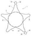
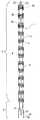
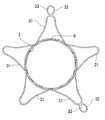
図1は、本発明の実施例の生体内留置用ステントの側面図(正面図)であり、図2は、図1に示したステントのA−A線断面であり、図3は、本発明の実施例の生体内留置用ステントを説明するための説明図であり、図4は、図1に示したステントを直線状にした状態の展開図である。図5は、図1に示したステントを縮径させるとともに直線状に変形させた状態のステントの側面図である。
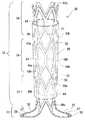
本発明の生体内留置用ステント1は、応力負荷時に外径が縮径する方向への変形が可能であるとともに応力負荷解除時に応力負荷前の形状に実質的に復元する自己拡張形ステントである。ステント1は、一端側から他端側に向かって縮径する筒状の本体部2と、本体部2の他端部もしくは他端部近傍よりステント1の軸方向に対して斜めに広がるように延びる生体内係止部3とを一体に備えている。
【0010】
そして、このステント1は、外側より負荷を与えることにより本体部は縮径し、生体内係止部は、本体部と直線状となるように変形する。
そして、この実施例では、ステント1は、線状体により一体に形成されたものとなっている。また、ステント1は、応力負荷時に外径が縮径する方向への変形が可能な複数の環状体4と複数の環状体4をステントの軸方向に配列した状態にて接続する接続部5とを備える本体部と、本体部の端部もしくは端部近傍に位置する環状体4と連続する生体内係止部3とを備えるものである。さらに、環状体は、波状線状体からなるものとなっている。そして、ステントは、後述する他の実施例のように本体部2の側面の全体もしくは一部分を封鎖する筒状カバー8を備えていることが好ましい。
【0011】
この実施例のステント1は、生体内挿入前および生体内挿入後のいずれにおいても超弾性を示す超弾性金属により一体に形成された生体内留置用ステントである。ステント1は、応力負荷時に外径が縮径する方向への変形が可能な複数の環状体4(言い換えれば、拡張要素)と、複数の環状体4をステント1の軸方向に配列した状態にて接続する接続部5(言い換えれば、接続要素)とにより構成されるとともに、一端側から他端側に向かって縮径する筒状の本体部2と、この本体部2の他端部(もしくは他端部近傍)より本体部の中心軸に対して所定角度斜め外方に延出する生体内係止部3を備える。ステント全体は、超弾性による弾性変形が可能である。この実施例のステント1は、ステントの軸方向に複数配列された環状体4と、複数の環状体4を接続する接続部5と、生体内係止部3を有する一体物である。
【0012】
この実施例のステント1では、図1および図4に示すように、超弾性を示す超弾性金属により形成され複数の応力負荷時に外径が縮径する方向への変形を補助する変形補助機能を有する環状体4が、ほぼ直線的に並ぶように配列されている。隣り合う環状体4は、接続部5により接続されている。この実施例のステント1は、ステント1の側面全体よりステントの中心方向に負荷をかけると、図5に示す状態に縮径するとともに直線状(言い換えれば、直管状)に変形させることができる。
この実施例のステント1では、図1、図4に示すように、拡張保持の役割を担う波状(ジグザグ状)かつ環状につながった線状体4からなる複数の環状体4を備え、これらの環状体4は接続部5(コネクター)により隣り合う環状体4が離反しないように接続されている。複数の環状体4は、軸方向に隣り合う波状環状体4の谷部と山部が近接するように軸方向にほぼ直線的に配列されている。
この環状体4は、上記のように波状(ジグザグ状)かつ環状につながった線状体4からなるため、応力負荷時に外径が縮径する方向への変形を補助する変形補助機能を有しており、かつ、超弾性を示す超弾性金属により形成されており、応力負荷を解除することにより作製時の形状に復元する。
そして、この実施例のステント1の接続部5は、隣り合う波状環状体4の谷部と近接する波状環状体4の山部をほぼ直線状に接続している。
【0013】
また、この実施例のステント1では、隣り合う環状体4は複数の接続部5により接続されている。このように、環状体4は複数の接続部5により接続することが好ましい。この場合、接続部5は、ほぼ向かい合う位置に2つ設けること、また、3つ以上の接続部5をステント1の中心軸に対してほぼ等角度となるように配置することが好ましい。この実施例では、隣り合う環状体4には、複数の近接する谷部と山部が形成されており、その谷部と山部が2つおきに接続部5より接続されている。また、この実施例のステント1では、環状体構成部分と接続部構成部分がステント1の軸方向に並んだ状態となっている。
そして、ステント1の本体部2は、図1に示すように、一端側より他端側(生体内係止部側)に向かって縮径するものとなっている。縮径形態は、一端側よりテーパー状に連続して縮径するもの、また、環状体ごとに段階的に縮径するものいずれであってもよい。この実施例のステント1では、本体部は、テーパー状に縮径するものとなっている。
【0014】
また、ステント1の一端部側(生体内係止部が設けられていない側)の環状体4(具体的には、4a,4b,4c)は、他の環状体より軸方向の長さが若干長いものとなっている。本体部の一端側の外径が、他端側に比べて大きいが、このようにすることにより、十分な拡張力を有するものとなる。
そして、ステント1の本体部における大きさなどは、留置対象部位により異なるが、一般的には以下の通りである。
ステントの本体部としては、一端(大径部)の外径が4〜25mm、ステントの本体部の他端(小径部)の外径が3〜22mm、ステントの本体部の一端(大径部)と他端(小径部)の外径の差が1〜5mm、長さは20〜200mm程度である。また、ステントの肉厚は、0.08〜0.3mm程度が好ましい。
特に、総胆管と十二指腸の乳頭部への留置用ステントの場合には、ステントの本体部の一端(大径部)の外径が8〜12mm、好ましくは9〜11mm、ステントの本体部の他端(小径部)の外径が6〜10mm、好ましくは7〜9mm、ステントの本体部の一端(大径部)と他端(小径部)の外径の差が1〜4mm、好ましくは2〜3mm、長さは、4〜10mm、好ましくは6〜8mmである。
上述したように、この実施例のステント1では、本体部2を構成する環状体4は、上記のように波状(ジグザグ状)かつ環状につながった線状体4からなるものであり、波の数は、6〜36程度が好適であり、特に、8〜24が好ましい。環状体4の長さは、1〜10mm、より好ましくは1.5〜5mmである。また、環状体4の数は、3〜30、より好ましくは5〜20である。そして、環状体4間の距離、言い換えれば、接続部5のステント1の軸方向の長さは、0.1〜5mm、好ましくは、0.15〜3mmが好ましい。また、接続部を構成する線状体の幅は、0.03〜0.2mm、より好ましくは0.05〜0.1mmである。
【0015】
また、図1、図4に示すように、ステント1の一端部にX線造影用マーカー22が設けられている。マーカー22は、ステント1の端部に形成された小開口21を閉塞するようにステントに固定されている。また、図1、図4に示すように、ステント1の本体部の他端部付近にX線造影用マーカー24が設けられている。マーカー24は、ステント1の他端部付近に形成された小開口23を閉塞するようにステントに固定されている。特に、この実施例では、他端部側の小開口23およびマーカー24は、本体部の最も端部に位置する接続部に設けられている。また、言い換えれば、マーカー24は、最も他端部に位置する環状体4とその環状体と隣り合う環状体間に設けられている。
このようなマーカーは、例えば、ステントに形成された小開口に、この小開口より若干小さいX線造影用物質の円盤状部材を配置し両面より押圧してかしめることにより取り付けられることが好ましい。なお、マーカーとしては、どのようなものであってもよく、上記のようなものに限定されない。例えば、X線造影性物質をステントの外面に被覆すること、またX線造影性物質により形成された線材を巻き付けたもの、さらには、X線造影性物質により形成されたリング状部材を取り付けたものなどであってもよい。なお、マーカーの形成材料としては、例えば、金、白金、タングステン、タンタルあるいはそれらの合金、あるいは銀−パラジウム合金等が好適である。
【0016】
そして、図1に示すように、ステント1は、本体部2の一端に位置する環状体4と連続するように形成された生体内係止部3を備えている。生体内係止部3は、本体部2の他端部(もしくは他端部近傍)よりステント1の軸方向に対して斜めに広がるように延びる。このステント1では、生体内係止部3は、複数の線状延出部31により構成されている。各線状延出部31は、両端が本体部と連続しており、自由端を持たない湾曲もしくは屈曲線状体である。具体的には、各延出部を構成する線状体の両端は、環状体の端部である谷部と一体となっている。そして、この実施例のステント1では、延出部31は、図2に示すように、ステントの中心軸に対してほぼ等角度となるように複数配置されている。延出部は、二つ以上設けることが好ましい。特に、3つ以上設けることが好ましい。また、延出部の数としては、2〜6個程度が好適である。
【0017】
さらに、このステント1では、生体内係止部3は、ステント1の端部(言い換えれば、生体内係止部の端部)となる部分付近に設けられた造影用マーカーを備えている。具体的には、延出部31は、延出部31の先端よりさらに延びる造影マーカー取付部32を備えており、取付部32には、造影マーカー33が固定されている。造影マーカー取付部および造影マーカーは、図2に示すように、2つ以上設けられていることが好ましい。なお、造影マーカー取付部および造影マーカーは、1つのみ設けてもよく、また、すべての延出部31に設けてもよい。マーカーの形成方法および形成材料としては、上述したものと同様のものが好適である。
【0018】
また、生体内係止部3は、ステントの軸に対して、45度から120度の角度にて斜めに広がるように延びるものであることが好ましい。ここでいう角度は、図3に示すように、生体内係止部3が含まれる仮想テーパー面とステント1の本体部の中心軸とのXとの間の角度αである。特に、上記の角度は、70〜100度が好ましい。また、生体内係止部3が含まれる仮想テーパー面の外端の直径Lは、ステント1の本体部2の直径の1.2〜3倍であることが好ましい。特に、1.5〜2倍であることが好ましい。生体内係止部3が含まれる仮想テーパー面の外端の直径Lには、図1および図2に示すように先端に突出する造影マーカーを備えるものにあってはそのマーカー形成部分を含まないものとすることが妥当である。
そして、ステント1の生体内係止部の大きさなどは、留置対象部位により異なるが、一般的には以下の通りである。
【0019】
延出部31が上述した実施例のように湾曲する線状体により形成されている場合には、本体部と連続する端部間の距離は、2〜5mmが好ましく、延出部の長さは、4〜10mmが好ましく、延出部のステントの軸方向の長さ(言い換えれば、上述した仮想テーパー面の高さ)は、0〜5mmが好ましく、生体内係止部3が含まれる仮想テーパー面の外端の直径Lは、3〜25mmが好ましい。延出部を構成する線状体の幅は、0.03〜0.2mm、より好ましくは0.05〜0.15mmである。また、延出部は、直線状態にしたときの長さは、5〜12mmが好ましい。
なお、延出部31の形状は、この実施例のようなものに限定されるものではなく、例えば、図9に示す実施例のステントが備えるもの、図10に示す実施例のステントが備えるものであってもよい。特に、図10に示すステントが備えるものは、延出部は、一端のみが本体部と連続する1本の線状体により形成されている。
【0020】
また、ステント1は、図6または図7に示すように、ステント1の本体部2の全体または一部の側面を封鎖する筒状カバー8を備えることが好ましい。なお、筒状カバー8は、生体内係止部には設けられていない。図6に示すものでは、筒状カバー8は、ステント1の本体部の全体ではなく部分的に設けられている。具体的には、ステント1の本体部2の一端部に到達しないように設けられており、このため、ステント1の一端部は露出した状態となっている。なお、カバーの他端側は、生体内係止部に到達しないように設けられている。このように、ステント1の一端部を露出させることにより、ステント1の係止部側への移動を規制することができる。なお、図8に示す実施例のように、本体部2の一端に到達するように、言い換えれば、本体部の全体に設けてもよい。
カバー8は、図6および図6のB−B線断面図である図7に示すように、ステント1の本体部の外側に設けられている。なお、筒状カバーは、ステント1の本体部の内側に設けてもよい。筒状カバーは、薄い被覆層でもある。筒状カバー8は、それが設けられる部分の本体部の側面全体を封鎖するものであってもよい。このように、本体部2に筒状カバー8を設けることにより、ステント1の本体部2の側面から体内組織がステント内に侵入することを防止できる。また、筒状カバー8をステント1の本体部2の内側に設けた場合には、ステント1の本体部2の内側には凹凸が生じないため、ステント内を血液、胆汁、食物等が通過しやすくなる。また、ステント1の外側には、ステント1の本体部2の骨格による凹凸が生じるため、体腔内に固定されやすく位置ずれが防止される。
【0021】
カバー8の厚さは、4〜50μm、特に、6〜20μmであることが好ましい。
カバー8の構成材料は、ゴム、エラストマー、可撓性樹脂が好ましい。ゴムとしては、例えば、シリコーンゴム、ラテックスゴムなどが好ましい。エラストマーとしては、フッ素系樹脂エラストマー、ポリウレタンエラストマー、ポリエステルエラストマー、ポリアミドエラストマー、ポリオレフィンエラストマー(例えば、ポリエチレンエラストマー、ポリプロピレンエラストマー)などが好ましい。可撓性樹脂としては、ポリウレタン、ポリエステル、ポリアミド、ポリ塩化ビニル、エチレン−酢酸ビニル共重合体、ポリオレフィン(例えば、ポリエチレン、ポリプロピレン、エチレン−プロピレン共重合体)などが好ましい。特に、エラストマー、ゴムが好適である。ゴムとしては、シリコーンゴムが好適である。さらに、シリコーンゴムとしては、低温硬化型もしくは常温硬化型シリコーンゴムが好ましい。また、カバー8は、あらかじめ作製したフィルムをステント31の内面に接合することにより形成したものであってもよい。フィルムの構成材料としては、上述したエラストマー、可撓性樹脂を用いることが好ましい。フィルムをステント1の本体部2に接着する際に使用する接着剤としては、本体部2と接着性の高いものを使用することが好ましい。接着剤としては、例えば、カバー形成材料として、シリコーン系材料を用いる場合には、シリカ系プライマーが好適であり、上述したようなエラストマーを用いる場合には、エポキシ樹脂系接着剤が好適である。
【0022】
また、ステント1の本体部を構成する環状体としては、上述した形態のものに限定されるものではない。
例えば、図9に示すような形態の環状体を用いるものであってもよい。
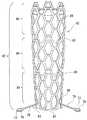
この実施例のステント50も、上述したステント1と同様に、応力負荷時に外径が縮径する方向への変形が可能であるとともに応力負荷解除時に応力負荷前の形状に実質的に復元する自己拡張形ステントである。ステント50は、一端側から他端側に向かって縮径する筒状の本体部52と、本体部52の端部よりステント52の軸方向に対して斜めに広がるように延びる生体内係止部53とを一体に備えている。
また、このステント50も上述したステント1と同様に、生体内挿入前および生体内挿入後のいずれにおいても超弾性を示す超弾性金属により略円筒形状に一体に形成された本体部と、生体内係止部を備える生体内留置用ステントである。
そして、このステント50は、外方より負荷を与えることにより本体部は縮径し、生体内係止部は、本体部と直線状となるように変形する。
【0023】
この実施例のステント50の環状体54は、側面に形成された複数の切欠部および複数の開口を備える線状構成物からなり、超弾性を示す金属により形成されている。
このステント50もステントの軸方向に複数配列された環状体54と、複数の環状体54を接続する接続部55と、生体内係止部53を構成する延出部56を有する一体物である。
この環状体54では、環状体の端部に切欠部を有するので、環状体54の端部63a,63bの変形が容易となり、特に、端部の部分的変形が可能となり、留置される血管の変形時に対する応答が良好になる。また、端部63は、複数のフレーム66aの端部により形成されているため、つぶれにくく、十分な強度を有する。また、両端部間には、フレーム66a,66bにより囲まれた開口64が形成されており、この開口64は、フレーム66aの変形により容易に変形する。このため、環状体54は、その中央部(フレーム体の中央部)での変形が容易である。
なお、この実施例では、開口64は、圧し潰された形状の六角形となっており、切欠部65は二等辺三角形となっている。また、切欠部65は、それぞれの端部に複数、具体的には6個形成されており、それぞれはほぼ等しい形状となっている。また、開口64もステント50の側面を形成するように、複数、具体的には、6個形成されている。なお、切欠部および開口は上記の形状および個数に限定されるものではなく、切欠部としては、3〜10個、開口としては、3〜10個程度が好適である。
【0024】
そして、この実施例のステント50では、軸方向に上述した環状体54が複数配列されており、かつ、隣り合う環状体54は接続部55により接続された状態となっている。この実施例のステント50では、3つの環状体54が直線状に配置され、かつ接続部55より接続された状態となっている。また、接続部55は、隣り合う環状体54の頂点と近接する環状体54の頂点を接続する。
また、この実施例のステント50では、隣り合う環状体54は複数の接続部55により接続されている。このように、環状体54は複数の接続部55により接続することが好ましい。この場合、接続部55は、ほぼ向かい合う位置に2つ設けること、また、3つ以上の接続部55をステント50の中心軸に対してほぼ等角度となるように配置することが好ましい。この実施例では、接続部55は、ほぼ向かい合う位置に2つ設けられている。
そして、ステント50の本体部における大きさなどは、留置対象部位により異なるが、上述したステント1において説明したとおりである。
【0025】
この実施例のステント50のような環状体54の場合には、環状体54の長さは、2〜4mm、より好ましくは2.5〜3.5mmである。また、環状体54の数は、3〜30、より好ましくは5〜20である。そして、環状体54間の距離、言い換えれば、接続部55のステント50の軸方向の長さは、0.1〜5mm、好ましくは0.15〜3mmが好ましい。また、環状体54を構成する線状体(フレーム)の幅は、0.08〜0.3mm、より好ましくは0.1〜0.2mmである。また、接続部55は、直線状態にしたときの長さは、0.15〜8mm、好ましくは0.2〜5mmであることが好ましい。また、接続部55を構成する線状体の幅は、0.03〜0.2mm、より好ましくは0.05〜0.1mmである。
【0026】
そして、ステント50の本体部52は、図9に示すように、一端側より他端側(生体内係止部側)に向かって縮径するものとなっている。縮径形態は、一端側よりテーパー状に連続して縮径するもの、また、環状体ごとに段階的に縮径するものいずれであってもよい。この実施例のステント50では、本体部は、テーパー状に縮径するものとなっている。
そして、図9に示すように、ステント50は、本体部52の一端に位置する環状体4と連続するように形成された生体内係止部53を備えている。ステント50は、本体部52の端部よりステント50の軸方向に対して斜めに広がるように延びる生体内係止部53とを一体に備えている。このステント50では、生体内係止部53は、複数の線状延出部56により構成されている。各線状延出部56は、両端が本体部と連続しており、自由端を持たない湾曲もしくは屈曲線状体である。具体的には、各延出部を構成する線状体の両端は、環状体の端部と一体となっている。そして、この実施例のステント50では、延出部56は、ステントの中心軸に対してほぼ等角度となるように複数配置されている。延出部は、二つ以上設けることが好ましい。特に、3つ以上設けることが好ましい。また、延出部の数としては、2〜5個程度が好適である。
【0027】
さらに、このステント50では、生体内係止部53は、ステント50の端部(言い換えれば、生体内係止部の端部)となる部分付近に設けられた造影用マーカーを備えている。具体的には、延出部56は、延出部56の先端部内に設けられた造影マーカー取付部57を備えており、取付部57には、造影マーカー58が固定されている。造影マーカー取付部および造影マーカーは、2つ以上設けられていることが好ましい。なお、造影マーカー取付部および造影マーカーは、1つのみ設けてもよく、また、すべての延出部56に設けてもよい。マーカーの形成方法および形成材料としては、上述したものと同様のものが好適である。
また、生体内係止部は、ステントの軸に対して、45度から120度の角度にて斜めに広がるように延びるものであることが好ましい。ここでいう角度は、図3に示したものと同様である。特に、上記の角度は、70〜100度が好ましい。また、生体内係止部53が含まれる仮想テーパー面の外端の直径Lは、ステント50の本体部52の直径の1.2〜3倍であることが好ましい。特に、1.5〜2倍であることが好ましい。
【0028】
そして、ステント50の生体内係止部の大きさなどは、留置対象部位により異なるが、一般的には以下の通りである。
延出部56が上述した実施例のように湾曲する線状体により形成されている場合には、本体部と連続する端部間の距離は、2〜5mmが好ましく、延出部の長さは、4〜10mmが好ましく、延出部のステントの軸方向の長さ(言い換えれば、上述した仮想テーパー面の高さ)は、0〜5mmが好ましく、生体内係止部53が含まれる仮想テーパー面の外端の直径Lは、3〜25mmが好ましい。延出部を構成する線状体の幅は、0.03〜0.2mm、より好ましくは0.05〜0.15mmである。また、延出部は、直線状態にしたときの長さは、5〜12mmが好ましくい。
なお、延出部56の形状は、この実施例のようなものに限定されるものではなく、例えば、図1および図2に示す実施例のステントが備えるもの、図10に示す実施例のステントが備えるものであってもよい。
【0029】
また、このステント50は、図9に示すように、ステント50の本体部52の一部の側面を封鎖する筒状カバー68を備えている。筒状カバー68は、本体部52の全体の側面を封鎖するものであってもよい。なお、筒状カバー68については、上述した筒状カバー8と同じものが好適に使用できる。
さらに、ステントとしては、図10に示すステント70のように、両端部に台形状の切欠部が形成されるとともに、中央部にハニカム状に複数の六角形の開口が形成された環状体74を用いるものでもよい。
【0030】
この実施例のステント70は、図10に示すように、拡張保持の役割を担う複数の環状体74とこれらの環状体74を接続する接続部75(コネクター)により隣り合う環状体4が離反しないように接続されることにより構成された本体部72と本体部72の端部と連続する生体内係止部73を備えている。
そして、ステント70の本体部72は、図10に示すように、一端側より他端側(生体内係止部側)に向かって縮径するものとなっている。縮径形態は、一端側よりテーパー状に連続して縮径するもの、また、環状体ごとに段階的に縮径するものいずれであってもよい。この実施例のステント1では、本体部は、テーパー状に縮径するものとなっている。
【0031】
そして、図10に示すように、ステント70は、本体部72の端部よりステント70の軸方向に対して斜めに広がるように延びる生体内係止部73とを一体に備えている。このステント70では、生体内係止部73は、複数の線状延出部76により構成されている。各線状延出部76は、一端が本体部に連続する棒状体であり、先端部が楕円状に形成されている。そして、この実施例のステント70では、延出部76は、ステントの中心軸に対してほぼ等角度となるように複数配置されている。延出部は、二つ以上設けることが好ましい。特に、3つ以上設けることが好ましい。また、延出部の数としては、2〜5個程度が好適である。
さらに、このステント70では、生体内係止部73は、ステント70の端部となる部分付近に設けられた造影用マーカーを備えている。具体的には、延出部76は、延出部76の先端部内に設けられた造影マーカー取付部77を備えており、取付部77には、造影マーカー78が固定されている。造影マーカー取付部および造影マーカーは、2つ以上設けられていることが好ましい。なお、造影マーカー取付部および造影マーカーは、1つのみ設けてもよく、また、すべての延出部76に設けてもよい。マーカーの形成方法および形成材料としては、上述したものと同様のものが好適である。
【0032】
また、生体内係止部は、ステントの軸に対して、45度から120度の角度にて斜めに広がるように延びるものであることが好ましい。ここでいう角度は、図3に示したものと同様である。特に、上記の角度は、70〜100度が好ましい。また、生体内係止部73が含まれる仮想テーパー面の外端の直径Lは、ステント70の本体部72の直径の1.2〜3倍であることが好ましい。特に、1.5〜2倍であることが好ましい。
なお、延出部76の形状は、この実施例のようなものに限定されるものではなく、例えば、図1および図2に示す実施例のステントが備えるもの、図9に示す実施例のステントが備えるものであってもよい。また、このステントも筒状カバー78を備えているが、カバー78については、上述した筒状カバー8と同じものが好適に使用できる。
【0033】
さらに、ステントとしては、図11に示すステント80のように、一端側から他端側に向かって縮径する筒状の本体部82と、本体部82の他端部近傍よりステント80の軸方向に対して斜めに広がるように延びる生体内係止部83とを一体に備えているものであってもよい。このステント80では、図12に示すように、生体内係止部83が本体部82の他端より若干一端側の位置より延びるものとなっている。そして、本体部82の他端部87が、生体内係止部83よりも突出した形態となっている。生体内係止部83より突出する本体部の長さ、言い換えれば、生体内係止部83の本体部82からの分岐部86から本体部の他端部87までの長さは、2〜8mm程度がよく、好ましくは4〜6mmが適当である。そして、この本体部82の他端部87部分の側面もカバー88により閉塞されている。
【0034】
膵頭癌やファーター乳頭部癌等が原因で乳頭部自身が閉塞する場合があり、その様な時には乳頭部より若干カバー部を十二指腸側に出して留置することが望ましい場合がある。この理由は、これらの癌が増殖して乳頭部を覆うように増大してくるため、それを見越して少し出して留置するものである。この実施例のステント80はそれに対応するものである。なお、生体内係止部83より突出する本体部分は、胆管そのものと接触するわけではないので、それほど拡張力が必要ではない。また、この部分は癌の増殖による閉塞を防ぐこと、また食物残渣が引っかかりにくくするため、カバーにより側面が閉塞されていることが好ましい。この実施例では、カバーは、ステント80の本体部82の内面に設けられている。なお、外面に設けてもよい。
【0035】
なお、この実施例のステントにおける生体内係止部83の形態は、上述した実施例のステント70のものと同じである。しかし、この実施例のステントにおいても、延出部76の形状は、この実施例のようなものに限定されるものではなく、例えば、図1および図2に示す実施例のステントが備えるもの、図9に示す実施例のステントが備えるものであってもよい。また、このステントも筒状カバー88を備えているが、カバー88については、上述した筒状カバー8と同じものが好適に使用できる。
【0036】
そして、上述したすべての実施例のステントにおいて、ステントを形成する材料としては、超弾性金属が好ましい。超弾性金属としては、超弾性合金が好適に使用される。ここでいう超弾性合金とは一般に形状記憶合金といわれ、少なくとも生体温度(37℃付近)で超弾性を示すものである。特に好ましくは、49〜53原子%NiのTiNi合金、38.5〜41.5重量%ZnのCu−Zn合金、1〜10重量%XのCu−Zn−X合金(X=Be,Si,Sn,Al,Ga)、36〜38原子%AlのNi−Al合金等の超弾性金属体が好適に使用される。特に好ましくは、上記のTiNi合金である。また、Ti−Ni合金の一部を0.01〜10.0%Xで置換したTi−Ni−X合金(X=Co,Fe,Mn,Cr,V,Al,Nb,W,Bなど)とすること、またはTi−Ni合金の一部を0.01〜30.0%原子で置換したTi−Ni−X合金(X=Cu,Pb,Zr)とすること、また、冷間加工率または/および最終熱処理の条件を選択することにより、機械的特性を適宜変えることができる。また、上記のTi−Ni−X合金を用いて冷間加工率および/または最終熱処理の条件を選択することにより、機械的特性を適宜変えることができる。
【0037】
そして、使用される超弾性合金の座屈強度(負荷時の降伏応力)は、5〜200kg/mm2(22℃)、より好ましくは、8〜150kg/mm2、復元応力(除荷時の降伏応力)は、3〜180kg/mm2(22℃)、より好ましくは、5〜130kg/mm2である。ここでいう超弾性とは、使用温度において通常の金属が塑性変形する領域まで変形(曲げ、引張り、圧縮)させても、変形の解放後、加熱を必要とせずにほぼ元の形状に回復することを意味する。
そして、ステントは、例えば、超弾性金属パイプを用いて、ステント非構成部分を除去(例えば、切削、溶解)することに作製され、これにより、一体形成物となっている。
【0038】
なお、本発明のステントの形成に用いられる超弾性金属パイプは、不活性ガスまたは真空雰囲気にて溶解しTi−Ni合金などの超弾性合金のインゴットを形成し、このインゴットを機械的に研磨し、続いて、熱間プレスおよび押し出しにより、太径パイプを形成し、その後順次ダイス引き抜き工程および熱処理工程を繰り返すことにより、所定の肉厚、外径のパイプに細径化し、最終的に表面を化学的または物理的研磨することにより製造することができる。
そして、この超弾性金属パイプによるステント基材の形成は、レーザー加工(例えば、YAGレーザー)、放電加工、化学エッチング、切削加工などにより行うことができ、さらにそれらの併用により行ってもよい。
【0039】
また、本発明のステントは、内面または外面、さらには両面に生体適合性材料を被覆してもよい。生体適合性材料としては、生体適合性材料を有する合成樹脂または金属が考えられる。ステントの表面を不活性な金属で被覆する方法としては、電気メッキ法を用いた金メッキ、蒸着法を用いたステンレスメッキ、スパッタ法を用いたシリコンカーバイド、窒化チタンメッキ、金メッキなどが考えられる。
また、合成樹脂としては、熱可塑系または熱硬化系の樹脂から選択できるが、例えば、ポリオレフィン(例えば、ポリエチレン、ポリプロピレン、エチレン−プロピレン共重合体など)、ポリ塩化ビニル、エチレン−酢酸ビニル共重合体、ポリアミドエラストマー、ポリウレタン、ポリエステル、フッ素樹脂、シリコーンゴム等が使用でき、好ましくは、ポリオレフィン、ポリアミドエラストマー、ポリエステルあるいはポリウレタン、また、生体内分解性樹脂(例えば、ポリ乳酸、ポリグリコール酸、両者のコポリマー)である。合成樹脂被膜は、ステントを構成するフレームの湾曲の妨げにならない程度に柔軟であることが好ましい。合成樹脂被膜の肉厚は、5〜300μm、好ましくは、10〜200μmである。
【0040】
ステントの表面に合成樹脂を薄く被覆する方法としては、例えば、溶融状態または溶液状態の合成樹脂の中に、超弾性金属パイプを挿入して被覆する方法、モノマーを超弾性金属パイプの表面で重合させながら被覆する化学蒸着などがある。極薄な樹脂被覆が要求される場合は、希薄溶液を用いた被覆、または化学蒸着が好適である。
さらに、より生体適合性材料を向上させるために、上記樹脂被膜に抗血栓性材料を被覆または固定してもよい。抗血栓性材料として、公知の各種の樹脂を単独または混合して使用することができるが、例えば、ポリヒドロキシエチルメタアクリレート、ヒドロキシエチルメタアクリレートとスチレンの共重合体(例えば、HEMA−St−HEMAブロック共重合体)などが好適に使用できる。
【0041】
そして、上述したすべての実施例のステントは、生体の管腔の特に出入り口部に適した形状となっている。出入り口部は位置が決まっているため正確な留置が必要であり、生体内係止部に造影マーカーを有するため、その動きで造影上で出入り口部の確認が可能である。また生体内係止部と本体部の異径形状により、1度留置すると脱落や位置移動を防止できる。さらに、ステント端部による傷がつかないまたは体液の流動を阻害しない。また、単一の管素材を加工して形成されているため、金属溶接などの部分がなく小さく折りたたむことが可能である。
【0042】
次に、本発明のステントの製造方法について説明する。
本発明のステントの製造方法は、略円筒形状のTi−Ni合金パイプであって塑性変形可能なものを準備し、該合金パイプの側面を部分的に除去して、応力負荷時に外径が縮径する方向への変形が可能となる形態の本体部分と生体内係止部となる部分を備えるステント基材を形成するステント基材形成工程と、このステント基材の少なくとも前記本体部分を所定の成形型に装着し、他端側から一端側に向かって拡径するように本体部分を所定形状とすることおよび前記生体内係止部となる部分を所定形状とする形態加工工程と、該形態加工工程が行われたステント基材に超弾性物性を付与するための加熱処理工程とを行うものである。
【0043】
また、本発明の生体留置用ステントの製造方法は、略円筒形状のTi―Ni合金パイプであって、塑性変形可能なものを準備し、該合金パイプの側面を部分的に除去して、応力負荷時に外径が拡張する方向への変形が可能となる形態の本体部分と生体内係止部となる部分を備えるステント基材を形成するステント基材形成工程と、このステント基材の本体部部分に相当する形状を備える本体部成形型と該本体部成形型の縮径部に着脱可能に取り付けられるとともに生体内係止部分に相当する形状を備える係止部成形型とからなる成形型を準備し、前記ステント基材の前記本体部分に前記本体成形型を縮径部側から挿入し、前記ステント基材の前記生体内係止部となる部分に前記係止部成形型を挿入し、続いて、前記本体部成形型に前記係止部成形型を取り付けることにより前記ステント基材を所定形状とする形態加工工程と、前記形態加工工程における形態を保持した状態にて超弾性物性を付与する過熱処理工程と行うものであることが好ましい。
【0044】
略円筒形状のTi−Ni合金パイプであって塑性変形可能なものは、例えば、以下のようにして準備できる。
Ti−Ni合金パイプは、不活性ガスまたは真空雰囲気にて溶解しTi−Ni合金などの超弾性を付与可能な合金のインゴットを形成し、このインゴットを機械的に研磨し、続いて、熱間プレスおよび押し出しにより、太径パイプを形成し、その後順次ダイス引き抜き工程および熱処理工程を繰り返すことにより、所定の肉厚、外径のパイプに細径化し、最終的に表面を化学的または物理的研磨することにより製造される。なお、Ti−Ni合金パイプとしては、上記の熱処理工程を超弾性を発現しない温度にて行うことにより、超弾性を備えず塑性変形可能なものが用いられる。パイプの外径としては、留置される生体部位に適合する外径より小径のものを準備することが好ましい。
そして、上記の合金パイプを用いてステント基材形成工程を行う。ステント基材形成工程は、側面を部分的に除去して、応力負荷時に外径が縮径する方向への変形が可能となる形態の本体部分と本体部の端部より延びる生体内係止部となる部分を備えるステント基材を形成する。
【0045】
このステント基材形成工程は、例えば、応力負荷時に外径が縮径する方向への変形が可能となる形態の複数の環状体と該複数の環状体をステントの軸方向に配列した状態にて接続する接続部とを備える本体部分と、生体内係止部となる部分を備えるステント基材を形成するものである。なお、このステント基材形性工程は、上記のものに限定されるものではなく、図10のような接続部を備えないものであってもよい。
そして、ステント基材を形成する工程は、例えば、レーザー加工(例えば、YAGレーザー)、放電加工、機械研磨などによる切削加工、または化学エッチングなどにより行うことができる。さらにそれらの併用により行ってもよい。
具体的には、ステント基材形性工程では、まず、Ti−Ni合金パイプを放電加工により、ステント基材とならない部分を加熱熔融させて除去し、ステント基材のほぼ目的形状に初期加工する一次加工工程を行う。続いて、一次加工処理したステント形成体のエッジを削りとる面取り工程(二次加工)を行う。面取り工程は、例えば、硬質微粒子を用いたブラスト処理することにより行われる。このブラスト処理によりバリ取りおよび面取りが行われる。そして、一次加工時にステント形成体の周縁に熱変性部分が形成される場合には、それを除去するために、熱変性部分処理工程(三次加工、化学エッチング)を行ってもよい。この熱変性部分処理工程は、例えば、フッ酸と硝酸の混合液に少量の過酸化水素液を混合した変性部処理液にブラスト処理したステント形成体を浸漬することにより行われる。なお、化学エッチング(熱変性部分処理工程)によって、バリ取りおよび面取りを同時に行ってもよく、この場合には、ブラスト処理工程は行わなくてもよい。
【0046】
また、Ti−Ni合金パイプより、ステント基材を形成する工程における上記の一次加工は、準備された所定の外径のTi−Ni合金パイプをレーザー装置(例えば、YAGレーザー装置)によりレーザー加工することにより行うことが好ましい。
また、Ti−Ni合金パイプより、ステント基材を形成する工程は、以下のようにフォトファブリケーション技術を用いて行ってもよい。
【0047】
この方法では、最初にTi−Ni合金パイプの内面、外面の脱脂、洗浄を行う。脱脂および洗浄は、例えば、界面活性剤水溶液中への浸漬、RO水中への浸漬、ヘキサンなどの洗浄用有機溶媒中への浸漬により行われる。そして、乾燥させた後、Ti−Ni合金パイプの外面および内面にフォトレジストを塗布する。フォトレジストとしては、ポジ型、ネガ型のいずれでもよく、さらに、UVレジスト、電子線レジスト、X線レジストでもよい。フォトレジストの膜厚としては、0.5〜4μm程度が好適である。そして、フォトレジスト膜のパイプへの密着性を高めるために、80〜90℃程度で加熱処理(プリベーキング)を行う。
【0048】
続いて、ステント基材の形状に対応した模様を有するマスキングフィルム(フォトレジストがポジ型、ネガ型により相違する)をTi−Ni合金パイプの外面に巻き付け真空密着させた後、露光作業を行う。露光作業は、例えば、超高圧水銀灯を用いて行うことができる。また、この際に全体に確実に照射されるようにTi−Ni合金パイプを回転させながら行うことが好ましい。そして、現像処理を行う。現像処理は、Ti−Ni合金パイプをフォトレジスト現像液に浸漬することにより行われる。続いて、120〜145℃に加熱しポストベーキング処理する。これにより、マスキング工程が終了する。
【0049】
このようにして、Ti−Ni合金パイプのステント基材非形成部分には、フォトレジストが存在せず、ステント基材形成部分には、硬化したフォトレジストが存在するTi−Ni合金パイプが作製される。エッチング液にこのステント形成体を浸漬し、ステント基材非形成部分を溶解し除去する。Ti−Ni合金パイプのステント基材非形成部分はエッチング液に接触するため溶解し、Ti−Ni合金パイプのステント基材形成部分は硬化したフォトレジストによりエッチング液に接触しないため溶解されない。このエッチング液処理により、ステントのほぼ外形をしたステント基材が作製される。そして、ステント基材の表面に付着している硬化フォトレジストを除去する。この処理は、硬化フォトレジストを溶解する溶液にステントを浸漬することにより行われる。さらに、ステントの周縁に形成されたバリの除去および面取りのために、上述のようにブラスト処理する。さらに、エッチング液に浸漬し、表面処理を行う。これにより、ステント基材が作製される。
さらに、必要により、ステントに金属メッキまたは樹脂被膜の形成工程が行われる。金属メッキ方法としては、電気メッキ法を用いた金メッキ、蒸着法を用いたステンレスメッキ、スパッタ法を用いたシリコンカーバイド、窒化チタンメッキ、金メッキなどが考えられる。
【0050】
次に、上記のステント基材の少なくとも本体部分を所定の成形型に装着し、他端側から一端側に向かって拡径するように本体部分を所定形状とすることおよび生体内係止部となる部分を所定形状とする形態加工工程を行う。
この工程は、ステント基材の本体部部分に相当する形状を備える本体部成形型92と本体部成形型91の縮径部に着脱可能に取り付けられるとともに生体内係止部分に相当する形状を備える係止部成形型92とからなる成形型90を準備し、ステント基材の本体部分に本体成形型91を縮径部側から挿入し、ステント基材の生体内係止部となる部分に係止部成形型92を縮径部側を挿入し、続いて、本体部成形型91に係止部成形型92を取り付けることによりステント基材を所定形状に変形させることにより行うことが好ましい。
【0051】
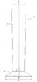
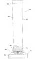
成形型90としては、例えば、図12に示すような、本体部成形型91と係止部成形型92とからなるものが用いられる。本体部成形型91は、本体部を形成するための緩やかなテーパー部91aを備え、係止部成形型92は、生体内係止部を形成するための急激なテーパー部92aを備え、2つの成形型91,92は、それぞれの小径部において着脱可能となっている。本体部成形型91と係止部成形型92は、例えば、本体部成形型91および係止部成形型92に設けられた一対のねじ部(雄ねじ91cおよび雌ねじ92c)により着脱可能となっている。なお、着脱機構は、このようなねじ式のものに限定されるものではなく、嵌合などによるものであってもよい。成形型の材料としては、ステント基材への超弾性付与のための熱処理工程に耐える耐熱性を有するものが好ましい。成形型の形成材料としては、各種金属が好ましく、特にステンレス鋼が好適である。
本体部成形型91には、テーパー部91aの拡径端と連続するストレート部分91bを備えていてもよい。係止部成形型92は、テーパー部92aの拡径端と連続するストレート部92bを備えていてもよい。
【0052】
この形態加工工程は、例えば、次のように行われる。
本体部成形型91と係止部成形型92とは、離脱した状態とする。ステント基材の本体部分内に本体成形型91を小径部側から挿入し、所定の位置に止める。ステント基材は徐々に拡張していき手を離してもその位置に止まるので、位置決めは容易である。次に係止部成形型92を小径部側より、ステント基材の生体内係止部となる部分の端部側内に挿入し、本体部成形型91に固定する。この実施例では、ステント基材の係止部は金属形成されており、係止部成形型も金属であるため摩擦抵抗は低く、ステント基材に余計な負荷をかけることなく、2つの成形型は容易に結合できる。最後に、ステント基材を若干動かす事によって最終的な位置決め(形状付け)を行う。
【0053】
また、図11に示したステント80のように、生体内係止部が、ステントの本体部の他端ではなく他端部近傍より延び、ステント本体部の他端部が生体内係止部の始端よりも突出するような形状を有するものの場合には、図13に示すような、成形型100を用いることにより、ステント基材の形態加工を容易に行うことができる。この成形型100の基本構成は、上述した成形型90と同じであり、同じ部分については、同じ符号を付してある。この成形型100では、本体成形型91と係止部成形型92との間に、ステント基材の他端部を収納するための溝部95を備えている。成形型の使用方法も上述したものと同じである。なお、ステント基材は、この成形型100に、本体部成形型のテーパー部91aと係止部成形型92のテーパー部92aの仮想接点96に、ステント基材の生体内係止部の始端が位置するようにセットされる。そして、図11に示すようなステントの場合には、ステント基材の本体部の他端部87は、溝部95に収納される。
【0054】
次に上記のように成形型に装着され形状付けされたステント基体を熱処理し、その形状の記憶及び超弾性の発現を行うステント基体熱処理工程を行う。
この加熱処理工程は、成形型にステント基体が装着された状態で行わなければならない。この熱処理工程は、例えば、ステント基体と成形型のセットされた状態でヒーターなどの加熱手段により加熱することも可能であるが、好ましくは、加熱炉(電気炉、マッフル炉等)に入れることによって行われる。加熱処理の雰囲気は、アルゴン、窒素などの不活性ガスの雰囲気で行われることが好ましいが、空気中であっても良い。この工程(熱処理工程)における加熱温度と時間は使用する成形型によって、その大きさによって異なるが、概ね350〜570度となった状態が、5〜60分維持されるように行うことが好ましい。
【0055】
そして、ステント基体を冷却した後、本体部成形型と係止部成形型のねじ係合をはずすことによって、ステント基体を取り出すことが出来る。冷却は空冷でも良いが好ましくは冷水等に投入する事による急冷却が好ましい。この工程によって得られたステント基体は、その形態において、本発明の形態を有し、かつ超弾性を備えるものである。
【0056】
次に、本発明のステントの使用方法について説明する。
ステントは、ガイドワイヤーが通る内管とシースの間に収納される。内管、シースおよびステントにより、生体内拡張器具が構成される。なお、ステントは、生体内係止部側がシースの先端側となるように収納される。内管にはステントのストッパーの役割をする凸部が取りつけられており、目的の部位で内管をそのままの位置にしてシースのみを引くと、引いた分だけステントがシースより露出し自己拡張する。
【0057】
次に、このステントを経皮経肝的に留置する場合の手順について述べる。ステントは、所定外径、例えば、外径8フレンチ(2.67mm)のシースに収納される。なお、シース内には、上述したように内管が挿入されている。生体内拡張器具は、経皮経肝的に生体内に導入され、先端は十二指腸に侵入しているガイドワイヤーに沿わせてさらに生体内に挿入する。生体内拡張器具の先端を一旦十二指腸に充分侵入させた後、シースを約5mm引いて、ステントの生体内係止部のみ露出させ、自己拡張させる。そして、シースと内管の位置関係を維持した状態にて、生体内拡張器具を引く。生体内係止部が乳頭部に当たると乳頭部は狭いので、係止部先端の造影マーカーが閉じる動きをする。この閉じる動きをしたところが乳頭部である。そこで、少し生体内拡張器具を押した後、シースを引くと、ステントの生体内係止部が、十二指腸壁にフィットする適切な位置にステントが留置される。このような位置であれば、生体内係止部は十二指腸壁にフィットしているため、十二指腸壁を傷つけたり潰瘍を起こすことがなく、また十二指腸にステント端が出ないので、食物が引っ掛かる事もない。また、ステントはテーパー形状のため、十二指腸側に脱落する事もない。また係止部があるため、ステントが総胆管側に位置ズレする事もない。また、係止部先端の造影マーカーの動きによって乳頭部の位置が分かるため、簡単かつ正確な留置が可能である。なお、経内視鏡的にステントを留置する場合は、乳頭の位置は分かっているので、目視で、造影マーカーを乳頭部にあわせておけば、正確な留置が可能となる。
【0058】
【実施例】
(実施例1)
TiNi合金(51原子%Ni)の合金パイプを冷間加工して、外径約8mm、肉厚0.24mm、長さ約40mmの金属パイプを準備した。そして、金属パイプを軸がぶれないようにファスナー機構の付いた回転モーター付治具にセットし、さらにこれを数値制御可能なXYテーブル上にセットした。そして、XYテーブルおよび回転モーターをパーソナルコンピュータに接続し、パーソナルコンピュータの出力が、XYテーブルの数値制御コントローラーおよび回転モーターに入力されるものとした。パーソナルコンピュータ内には図面ソフトが記憶されており、ここに図4に示すような構図のステントの展開図面を入力した。
このような構成により、パーソナルコンピュータより出力される図面データに基づいて、XYテーブルおよび回転モーターが駆動する。そこにレーザーを照射することにより、ステント基材を作製した。
【0059】
上記金属パイプのレーザー加工条件としては、電流値25A,出力1.5W、駆動スピード10mm/分にて行った。なお、上記のようなシステムに限らず、レーザー加工機が駆動するいわゆるレーザーマーカー(ガルバノメーター方式)であってもよい。
そして、化学研磨液を加温したものに、上記のフレーム基材を約2分間浸漬し、面取り(バリ取り、化学研磨)を行った。
このようにして作製したステントは、外径約8mm、全長40mm、肉厚0.2mm、環状体(拡張要素)における線状体の幅0.12mm、接続部(コネクター要素)の幅0.06mm、生体内係止部における線状体の幅0.12mmであり、全体が塑性変形するステント基材を得た。
次に、ステント基材の内径より若干大きい外径8mmの金属製の棒にステント基材を装着する。そして、マーカー取付用の小開口(直径0.7mm)より若干小さい直径でかつ厚さ若干ステント基材の肉厚より厚い円盤状の金マーカー用チップを用意し、たたいてマーカー取付用開口に取り付けた。
【0060】
次に、図12に示すステンレス製の成形型を準備し、ステント基材を生体内係止部側から挿入する。ステント基材と構成する線状体は、ジグザグ形状のため10mmまでは容易に広がる事ができ、係止部も容易に広がる。そして、成形型に装着した後、ステント基材を押圧して、成形型に密着させた。なお、成形型は、同一外径に形成された一端側円柱部(外径10mm)、この円柱部の端部より他端側に向かってなだらかに縮径する第1のテーパー部(長さ57mm、細径部外径8mm)と、この第1のテーパー部の端部より急激に拡径する第2のテーパー部(第1のテーパー部の中心軸に対する角度70度、軸方向の長さ5mm、最大外径16mm)と、第2のテーパー部の端部よりほぼ同一外径にて延びる他端側円柱部を備えている。
次に、ステント基材を成形型とともに、約500〜550度の電気炉に入れ30分〜1時間放置し加熱した。加熱後直ちに水に浸漬して急冷却を行った。そして、ステント基材を成形型から外し、上記の加熱によってニッケルチタン合金の表面に生成された酸化皮膜を化学研磨して除去し、本発明のステントを作製した。
【0061】
このようにして作製したステントは、本体部における一端側外径約10mm、他端側外径約8mmm、長さ約60mm、生体内係止部における本体部の中心軸に対する角度70度、軸方向の長さ5mm、最大外径16mmであった。
(実施例2)
実施例1のステントの本体部のテーパー形状に合致したテーパー形状を有するテトラフルオロエチレン製の棒を準備し、この棒に実施例1のステントの本体部を装着した。次に低温硬化型シリコーン溶液に、本体部のみを浸漬し引き上げた後、150度に加温しシリコーンを硬化させた。冷却後、棒からステントを取り出し、本発明のステントを得た。
【0062】
【発明の効果】
本発明の生体内留置用ステントは、応力負荷時に外径が縮径する方向への変形が可能であるとともに応力負荷解除時に応力負荷前の形状に実質的に復元する自己拡張形ステントであって、該ステントは、一端側から他端側に向かって縮径する筒状の本体部と、該本体部の他端部もしくは他端部近傍より該ステントの軸方向に対して斜めに広がるように延びる生体内係止部とを一体に備えている。このステントによれば、生体管腔の出入り口部への留置に適し、留置後の移動が極めて少ない。
また、前記ステントが線状体により一体に形成されたものであれば、ステントの圧縮が容易なものとなる。
また、前記ステントが応力負荷時に外径が縮径する方向への変形が可能な複数の環状体と、該複数の環状体をステントの軸方向に配列した状態にて接続する接続部と、該ステントの端部に位置する環状体の端部と連続する前記生体内係止部とを備えるものであれば、縮径時と自己拡張時における長さの変化が少なく、ステントを良好に留置できる。
【0063】
また、前記環状体が波状線状体もしくは側面に形成された複数の切欠部および複数の開口を形成する線状体からなるものであれば、より、縮径時と自己拡張時における長さの変化が少なく、ステントを良好に留置できる。
また、前記ステントは、前記本体部の側面の全体もしくは一部分を封鎖する筒状カバーを備えているものであれば、ステント内への生体組織の侵入を防止でき、ステント内における再狭窄を防止できる。
また、前記ステントが隣り合う前記環状体間に2以上の接続部を有しているものであれば、環状体間の連結が確実なものとなり、環状体が分離することを防止する。
【0064】
また、前記生体内係止部が前記本体部の他端部からステントの軸方向に対して所定の角度を持って延びる線状体により形成されているものであれば、ステントの生体内への係止が良好なものとなる。
また、前記生体内係止部が前記線状体を複数有するものであれば、ステントの生体内への係止がより良好なものとなる。
また、前記生体内係止部が前記本体部の他端部からステントの軸方向に対して所定の角度を持って延びるとともに両端が前記本体部の端部と接続する湾曲もしくは屈曲線状体により形成されているものであれば、係止部が生体内組織に損傷を与えることを確実に防止できる。
また、前記生体内係止部が複数の前記湾曲もしくは屈曲線状体を備えるものであれば、ステントの生体内への係止がより良好なものとなる。
また、前記生体内係止部が前記ステントの軸に対して、45度から120度の角度にて斜めに広がるように延びるものであれば、ステントの生体内への係止がより良好なものとなる。
また、前記生体内係止部が前記ステントの端部となる部分付近に設けられた造影用マーカーを備えているものであれば、ステントの生体内への留置操作が容易なものとなる。
【0065】
また、本発明の生体内留置用ステントの製造方法は、略円筒形状のTi−Ni合金パイプであって塑性変形可能なものを準備し、該合金パイプの側面を部分的に除去して、応力負荷時に外径が縮径する方向への変形が可能となる形態の本体部分と生体内係止部となる部分を備えるステント基材を形成するステント基材形成工程と、このステント基材の少なくとも前記本体部分を所定の成形型に装着し、他端側から一端側に向かって拡径するように本体部分を所定形状とすることおよび前記生体内係止部となる部分を所定形状とする形態加工工程と、該形態加工工程が行われたステント基材に超弾性物性を付与するための加熱処理工程とを行うものである。
このステントの製造方法によれば、上述した効果を備えるステントを容易に製造することができる。
【図面の簡単な説明】
【図1】図1は、本発明の実施例の生体内留置用ステントの側面図である。
【図2】図2は、図1に示したステントのA−A線断面である。
【図3】図3は、本発明の実施例の生体内留置用ステントを説明するための説明図である。
【図4】図4は、図1に示したステントを直線状にした状態の展開図である。
【図5】図5は、図1に示したステントを縮径させるとともに直線状に変形させた状態のステントの側面図である。
【図6】図6は、本発明の他の実施例の生体内留置用ステントの側面図である。
【図7】図7は、図6に示したステントのB−B線断面である。
【図8】図8は、本発明の他の実施例の生体内留置用ステントの側面図である。
【図9】図9は、本発明の他の実施例の生体内留置用ステントの斜視図である。
【図10】図10は、本発明の他の実施例の生体内留置用ステントの斜視図である。
【図11】図11は、本発明の他の実施例の生体内留置用ステントの斜視図である。
【図12】図12は、本発明のステントの製造に用いられる成形型の一例の正面図である。
【図13】図13は、本発明のステントの製造に用いられる成形型の他の例の正面図である。
【符号の説明】
1 生体内留置用ステント
2 本体部
3 生体内係止部[0001]
BACKGROUND OF THE INVENTION
The present invention relates to a self-expanding in-vivo stent that is used to improve a stenosis or occlusion occurring in a lumen of blood vessels, bile ducts, trachea, esophagus, urethra, and other organs. In particular, narrowing of entrances and exits, such as the Ferta papilla opening from the bile duct to the duodenum, the prostate opening from the bladder to the urethra, the cardia connecting from the esophagus to the stomach, and the entrance opening from the renal artery to the aorta The present invention relates to a self-expanding stent for implantation and placement at a site of a lesion or occlusion.
[0002]
[Prior art]
Many patent applications have been filed for self-expanding stents and are actually used. However, a stent having a shape that can be adapted to the entrance / exit of a lumen in a living body is not found in the prior art.
For example, Japanese Patent Publication No. 2002-505149 (Patent Document 1) discloses a self-expanding stent having a tapered shape. The feature is that the properties, that is, the expansion force or the structure are different in each of the maximum diameter portion, the intermediate diameter portion, and the minimum diameter portion. As an object to be used for this stent, it is exemplified that the diameter of the blood vessel and the diameter of the stent are matched with each other, for example, at the branch portion of the internal carotid artery and the external carotid artery. However, with only the tapered shape, the position of the stent may shift due to pulsation or peristaltic movement of the lumen.
In addition, International Publication WO99 / 45861 (Patent Document 2) discloses a urinary stent from the bladder to the urethra. This stent includes a stent in which a wire is knitted in a mesh shape and a locking wire material in which one wire is bent into a petal shape. However, since a stent knitted in a mesh shape is inserted into the body, the stent length increases when the diameter is folded small, so that the stent cannot be placed in an accurate position. In addition, since the locking wire is formed by folding a single wire, there is a drawback that the wire is difficult to connect to the stent end and the locking effect cannot be expected.
Japanese Patent Laid-Open No. 11-505441 (Patent Document 3) discloses a stent cut out from a metal pipe. With such a zigzag shape, there is no disadvantage that the stent length increases when the diameter is reduced, but there is no idea of detention at the entrance / exit part.
In addition, although Japanese National Patent Publication No. 9-501089 (Patent Document 4) discloses a stent in which both ends of the stent are open, it cannot function as a locking portion.
[0003]
[Patent Document 1]
JP-T-2002-505149
[Patent Document 2]
International Publication No. WO99 / 45861
[Patent Document 3]
Japanese Patent Application Laid-Open No. 11-505441
[Patent Document 4]
Japanese National Patent Publication No. 9-501089
[0004]
[Problems to be solved by the invention]
The stent for in-vivo indwelling of the present invention is indwelled at the entrance / exit part of the lumen. The entrance / exit part of a lumen exists in various places in the living body. The entrance / exit of the lumen will be described by taking the common bile duct and duodenal papilla as examples. When pancreatic cancer, especially pancreatic head cancer, becomes large, cancer develops in the nipple and obstructs the nipple from the lower common bile duct. Due to the blockage of the papilla, bile is not excreted into the duodenum, resulting in jaundice. Therefore, a self-expanding stent has been placed on the nipple. In a stent composed only of a metal wire, there is a problem that cancer grows in the stent through between the wires and eventually re-occludes. In recent years, a covered stent in which a stent is covered with a thin film has been used to prevent this. As an indwelling position, the indwelling position is often placed so as to penetrate the lower part of the common bile duct, the nipple, and the duodenum. In such a case, one end of the stent is in the duodenum. There are three problems with such placement. One is that the stent falls off to the duodenum side or moves to the common bile duct side. The movement of the stent position is caused by a peristaltic movement for excreting bile in the common bile duct into the duodenum or by patient movement. Second, because the end of the stent protrudes toward the duodenum, the sharp end of the stent damages the duodenal wall, causing bleeding and ulceration, and food that passes through the duodenum is caught on the end of the stent and inhibits flow. Is to do. The third is that it is difficult to place the detention accurately. As a method for placing a biliary stent in general, there are a transcutaneous transhepatic method and a transendoscopic method. When performing transendoscopically, since it is performed while observing the nipple with the eyes, it is easy to place it relatively accurately. However, since this is a catheter operation through a long endoscope, skill is required in that respect. In the percutaneous transhepatic approach, the position is confirmed by injecting a contrast medium, but it is difficult to accurately grasp the position of the nipple in millimeters.
The above-mentioned
The object of the present invention is to solve the above-mentioned problems and to provide a self-expanding stent that is suitable for placement at the entrance / exit of a living body lumen and that moves very little after placement.
[0005]
[Means for Solving the Problems]
What achieves the above object is as follows.
(1) A self-expanding stent that can be deformed in a direction in which the outer diameter is reduced when stress is applied, and that is substantially restored to the shape prior to stress application when the stress is released, A cylindrical main body portion whose diameter decreases from the other end side to the other end side, and an in-vivo locking portion extending so as to spread obliquely with respect to the axial direction of the stent from the other end portion of the main body portion or the vicinity of the other end portion An in-vivo indwelling stent.
(2) The in-vivo indwelling stent according to (1), wherein the stent is integrally formed of a linear body.
(3) The stent includes a plurality of annular bodies that can be deformed in a direction in which the outer diameter is reduced when stress is applied, and a connection portion that connects the plurality of annular bodies in a state in which they are arranged in the axial direction of the stent. The in vivo indwelling according to the above (1) or (2), comprising: a main body portion provided; and the in vivo locking portion continuous with the annular body located at or near the end of the main body portion. Stent.
(4) The annular body includes a wavy linear body or a linear body that forms a plurality of cutout portions and a plurality of openings formed on a side surface, according to any one of (1) to (3). In vivo indwelling stent.
(5) The in-vivo stent according to any one of (1) to (4), wherein the stent includes a cylindrical cover that seals all or a part of a side surface of the main body.
(6) The in-vivo indwelling stent according to any one of (1) to (5), wherein the stent has two or more connecting portions between the adjacent annular bodies.
[0006]
(7) The in vivo locking portion is formed of a linear body extending at a predetermined angle with respect to the axial direction of the stent from the other end portion or the vicinity of the other end portion of the main body portion. Thru | or the stent for indwelling in any one of (6).
(8) The in vivo indwelling stent according to (7), wherein the in vivo locking portion includes a plurality of the linear bodies.
(9) The in-vivo locking portion extends from the other end portion of the main body portion at a predetermined angle with respect to the axial direction of the stent, and has a curved or bent line shape in which both ends are connected to the end portion of the main body portion. The in-vivo indwelling stent according to any one of (1) to (8), wherein the stent is formed by a body.
(10) The in-vivo indwelling stent according to (9), wherein the in-vivo locking portion includes a plurality of the curved or bent linear bodies.
(11) The in vivo locking portion according to any one of (1) to (10), wherein the in vivo locking portion extends so as to spread obliquely at an angle of 45 degrees to 120 degrees with respect to the axis of the stent. In vivo indwelling stent.
(12) The in vivo indwelling stent according to any one of (1) to (11), wherein the in vivo locking portion includes a contrast marker provided in the vicinity of a portion serving as an end of the stent. .
(13) The stent for in-vivo placement according to any one of (1) to (12), wherein the stent is made of a superelastic metal or a nickel titanium alloy.
[0007]
Moreover, what achieves the said objective is as follows.
(14) A substantially cylindrical Ti-Ni alloy pipe that can be plastically deformed is prepared, and the side surface of the alloy pipe is partially removed, and the outer diameter is reduced in a direction in which the outer diameter is reduced when stress is applied. A stent base material forming step for forming a stent base material having a main body portion and a portion serving as an in vivo locking portion, and at least the main body portion of the stent base material is attached to a predetermined mold. Forming the body part into a predetermined shape so as to increase the diameter from the other end side toward the one end side, and a morphological processing step for forming the part that becomes the in-vivo locking portion into a predetermined shape, and the morphological processing step were performed The manufacturing method of the stent for indwelling which performs the heat processing process for providing a superelastic property to a stent base material.
[0008]
Moreover, what achieves the said objective is as follows.
(15) A substantially cylindrical Ti-Ni alloy pipe that can be plastically deformed is prepared, and the side surface of the alloy pipe is partially removed to deform the outer diameter to expand when stress is applied. A stent base material forming step for forming a stent base material including a main body portion and a portion serving as an in vivo locking portion, and a main body mold having a shape corresponding to the main body portion of the stent base material And a locking part molding die that is removably attached to the reduced diameter part of the body part molding die and has a shape corresponding to the in-vivo locking part, and preparing the body part of the stent base material The main body molding die is inserted from the reduced diameter portion side, the locking portion molding die is inserted into a portion of the stent base material that becomes the in-vivo locking portion, and then, the engagement portion molding die is engaged with the main body portion molding die. By attaching the stopper mold, the stainless steel A method for producing a living indwelling stent, comprising: a morphological processing step for forming a base material in a predetermined shape; and a superheat treatment step for imparting superelastic properties in a state in which the configuration in the morphological processing step is maintained.
(16) The method for manufacturing an indwelling stent according to (14) or (15), wherein the alloy pipe is prepared with a diameter smaller than an outer diameter suitable for expansion of a living body part to be placed.
(17) In the stent base material forming step, a plurality of annular bodies in a form that allows deformation in a direction in which the outer diameter is reduced when stress is applied, and the plurality of annular bodies are arranged in the axial direction of the stent. The in-vivo indwelling stent according to any one of the above (14) to (16), which forms a stent base material including a main body portion including a connection portion to be connected to each other and a portion serving as an in-vivo locking portion. Manufacturing method.
(18) The body part molding die includes a gently tapered part for forming the body part, and the locking part molding die includes a sharp taper part for forming the in vivo locking part, The manufacturing method of the in-vivo stent according to any one of the above (14) to (17), wherein the two molds are detachable at their small diameter portions.
(19) The above-mentioned (14) to (18), wherein a groove portion for accommodating the other end portion of the main body portion of the stent base is formed in the attachment portion portion of the main body mold and the locking mold. The manufacturing method of the stent for indwelling in any one of these.
[0009]
DETAILED DESCRIPTION OF THE INVENTION
The in-vivo stent according to the embodiment of the present invention will be described.
FIG. 1 is a side view (front view) of a stent for in vivo placement according to an embodiment of the present invention, FIG. 2 is a cross-sectional view taken along line AA of the stent shown in FIG. 1, and FIG. It is explanatory drawing for demonstrating the stent for in-vivo of the Example of FIG. 4, FIG. 4 is an expanded view of the state which made the stent shown in FIG. 1 linear. FIG. 5 is a side view of the stent in a state where the diameter of the stent shown in FIG. 1 is reduced and linearly deformed.
The in-
[0010]
The
In this embodiment, the
[0011]
The
[0012]
As shown in FIGS. 1 and 4, the
As shown in FIGS. 1 and 4, the
Since the
And the
[0013]
In the
And as shown in FIG. 1, the main-
[0014]
In addition, the annular body 4 (specifically, 4a, 4b, 4c) on one end side of the stent 1 (the side where the in-vivo locking portion is not provided) has a longer axial length than the other annular bodies. It is a little long. Although the outer diameter of the one end side of the main body is larger than that of the other end side, by doing so, it has a sufficient expansion force.
And although the magnitude | size in the main-body part of the
As the main part of the stent, the outer diameter of one end (large diameter part) is 4 to 25 mm, the outer diameter of the other end (small diameter part) of the stent is 3 to 22 mm, and one end of the main part of the stent (large diameter part) ) And the other end (small diameter portion) have a difference in outer diameter of 1 to 5 mm and a length of about 20 to 200 mm. The thickness of the stent is preferably about 0.08 to 0.3 mm.
In particular, in the case of a stent for placement in the common bile duct and duodenal papilla, the outer diameter of one end (large diameter portion) of the main body of the stent is 8 to 12 mm, preferably 9 to 11 mm. The outer diameter of the end (small diameter portion) is 6 to 10 mm, preferably 7 to 9 mm, and the difference in outer diameter between one end (large diameter portion) and the other end (small diameter portion) of the main body of the stent is 1 to 4 mm, preferably 2 -3 mm, length is 4-10 mm, preferably 6-8 mm.
As described above, in the
[0015]
As shown in FIGS. 1 and 4, an
Such a marker is preferably attached, for example, by placing a disk-shaped member made of an X-ray contrast medium slightly smaller than the small opening formed in the stent and pressing it from both sides for caulking. In addition, as a marker, what kind of thing may be sufficient and it is not limited to the above. For example, the outer surface of a stent is covered with an X-ray contrast material, a wire formed of an X-ray contrast material is wound, and a ring-shaped member formed of an X-ray contrast material is attached. It may be a thing. As the marker forming material, for example, gold, platinum, tungsten, tantalum or alloys thereof, or a silver-palladium alloy is suitable.
[0016]
And as shown in FIG. 1, the
[0017]
Further, in this
[0018]
Moreover, it is preferable that the in-vivo latching | locking
And although the magnitude | size of the in-vivo latching | locking part of the
[0019]
When the
In addition, the shape of the
[0020]
Moreover, it is preferable that the
The
[0021]
The thickness of the
The constituent material of the
[0022]
Further, the annular body constituting the main body portion of the
For example, an annular body having a form as shown in FIG. 9 may be used.
Similar to the
Further, similarly to the
The
[0023]
The
The
Since the
In this embodiment, the
[0024]
In the
Further, in the
And although the magnitude | size in the main-body part of the
[0025]
In the case of an
[0026]
And as shown in FIG. 9, the main-
And as shown in FIG. 9, the
[0027]
Further, in this
The in-vivo locking portion preferably extends so as to spread obliquely at an angle of 45 degrees to 120 degrees with respect to the axis of the stent. The angle here is the same as that shown in FIG. In particular, the angle is preferably 70 to 100 degrees. Moreover, it is preferable that the diameter L of the outer end of the virtual tapered surface including the in-vivo locking portion 53 is 1.2 to 3 times the diameter of the
[0028]
And although the magnitude | size of the in-vivo latching | locking part of the
When the extending
In addition, the shape of the
[0029]
Further, as shown in FIG. 9, the
Further, as a stent, as shown in a
[0030]
In the
And as shown in FIG. 10, the main-
[0031]
As shown in FIG. 10, the
Further, in this
[0032]
The in-vivo locking portion preferably extends so as to spread obliquely at an angle of 45 degrees to 120 degrees with respect to the axis of the stent. The angle here is the same as that shown in FIG. In particular, the angle is preferably 70 to 100 degrees. Moreover, it is preferable that the diameter L of the outer end of the virtual tapered surface including the in-
In addition, the shape of the
[0033]
Furthermore, as the
[0034]
In some cases, the nipple itself may be blocked due to pancreatic cancer, phatter cancer, etc. In such a case, it may be desirable to place the cover part slightly beyond the nipple in the duodenum side. The reason for this is that these cancers grow and grow so as to cover the nipple, so that they are placed in a little place in anticipation of it. The
[0035]
The form of the in-
[0036]
In all the stents of the above-described embodiments, a superelastic metal is preferable as a material for forming the stent. As the superelastic metal, a superelastic alloy is preferably used. The superelastic alloy here is generally called a shape memory alloy, and exhibits superelasticity at least at a living body temperature (around 37 ° C.). Particularly preferably, a TiNi alloy of 49 to 53 atomic% Ni, a Cu—Zn alloy of 38.5 to 41.5 wt% Zn, a Cu—Zn—X alloy of 1 to 10 wt% X (X = Be, Si, Sn, Al, Ga), a super elastic metal body such as a 36-38 atomic% Al Ni-Al alloy is preferably used. The TiNi alloy is particularly preferable. Further, a Ti—Ni—X alloy in which a part of the Ti—Ni alloy is substituted with 0.01 to 10.0% X (X = Co, Fe, Mn, Cr, V, Al, Nb, W, B, etc.) Or a Ti—Ni—X alloy (X = Cu, Pb, Zr) in which a part of the Ti—Ni alloy is substituted by 0.01 to 30.0% atoms, and the cold work rate Alternatively, mechanical properties can be appropriately changed by selecting conditions for the final heat treatment. Further, the mechanical characteristics can be appropriately changed by selecting the cold work rate and / or the final heat treatment conditions using the Ti—Ni—X alloy.
[0037]
And, the buckling strength (yield stress under load) of the superelastic alloy used is 5 to 200 kg / mm.2 (22 ° C.), more preferably 8 to 150 kg / mm2 Restoring stress (yield stress at unloading) is 3 to 180 kg / mm2 (22 ° C.), more preferably 5 to 130 kg / mm2 It is. Superelasticity here means that even if it is deformed (bending, pulling, compressing) to a region where normal metal is plastically deformed at the operating temperature, it is restored to its original shape without requiring heating after the deformation is released. Means that.
And a stent is produced by removing (for example, cutting, melt | dissolving) a stent non-component part, for example using a superelastic metal pipe, and, thereby, is an integral formation.
[0038]
The superelastic metal pipe used for forming the stent of the present invention is melted in an inert gas or vacuum atmosphere to form a superelastic alloy ingot such as a Ti-Ni alloy, and this ingot is mechanically polished. Subsequently, a thick pipe is formed by hot pressing and extrusion, and then a die drawing process and a heat treatment process are sequentially repeated to reduce the diameter of the pipe to a predetermined wall thickness and outer diameter, and finally the surface. It can be produced by chemical or physical polishing.
And formation of the stent base material by this superelastic metal pipe can be performed by laser processing (for example, YAG laser), electric discharge processing, chemical etching, cutting processing, etc., and may be performed by using them together.
[0039]
In addition, the stent of the present invention may be coated with a biocompatible material on the inner surface or outer surface, and further on both surfaces. The biocompatible material may be a synthetic resin or metal having a biocompatible material. As a method for coating the surface of the stent with an inert metal, gold plating using an electroplating method, stainless steel plating using a vapor deposition method, silicon carbide using a sputtering method, titanium nitride plating, gold plating, or the like can be considered.
The synthetic resin can be selected from thermoplastic or thermosetting resins. For example, polyolefin (for example, polyethylene, polypropylene, ethylene-propylene copolymer, etc.), polyvinyl chloride, ethylene-vinyl acetate copolymer. Polymer, polyamide elastomer, polyurethane, polyester, fluororesin, silicone rubber, etc. can be used, preferably polyolefin, polyamide elastomer, polyester or polyurethane, and biodegradable resins (for example, polylactic acid, polyglycolic acid, both Copolymer). The synthetic resin coating is preferably flexible to the extent that it does not hinder the bending of the frame constituting the stent. The thickness of the synthetic resin coating is 5 to 300 μm, preferably 10 to 200 μm.
[0040]
As a method of thinly coating the surface of the stent with a synthetic resin, for example, a method in which a superelastic metal pipe is inserted into a synthetic resin in a molten state or a solution state, and a monomer is polymerized on the surface of the superelastic metal pipe. There are chemical vapor deposition and the like to coat while. When an extremely thin resin coating is required, coating using a dilute solution or chemical vapor deposition is preferable.
Furthermore, in order to improve the biocompatible material, an antithrombotic material may be coated or fixed on the resin coating. As the antithrombogenic material, various known resins can be used alone or in combination. For example, polyhydroxyethyl methacrylate, a copolymer of hydroxyethyl methacrylate and styrene (for example, HEMA-St-HEMA) Block copolymers) can be used preferably.
[0041]
The stents of all the embodiments described above have a shape suitable for the entrance / exit part of the body lumen. Since the entrance / exit part has a fixed position, it is necessary to place the entrance / exit part accurately, and since the contrasting marker is provided in the in-vivo locking part, the entrance / exit part can be confirmed on the contrast by the movement. In addition, due to the different diameter shapes of the in-vivo locking part and the main body part, it is possible to prevent dropping and position movement once indwelling. Furthermore, it does not scratch the stent end or impede fluid flow. Moreover, since it is formed by processing a single tube material, it can be folded small without metal welding or the like.
[0042]
Next, the manufacturing method of the stent of this invention is demonstrated.
The stent manufacturing method of the present invention provides a substantially cylindrical Ti-Ni alloy pipe that can be plastically deformed, partially removes the side surface of the alloy pipe, and reduces the outer diameter when stress is applied. A stent base material forming step of forming a stent base material having a main body portion capable of being deformed in a radial direction and a portion serving as an in-vivo locking portion; and at least the main body portion of the stent base material is A form processing step of attaching the mold to the mold and making the main body part into a predetermined shape so as to increase the diameter from the other end side toward the one end side, and forming the part that becomes the in-vivo locking part into a predetermined shape, and the form And a heat treatment step for imparting superelastic properties to the stent base material on which the processing step has been performed.
[0043]
Further, the manufacturing method of the stent for indwelling according to the present invention provides a substantially cylindrical Ti—Ni alloy pipe that can be plastically deformed, partially removes the side surface of the alloy pipe, A stent base material forming step for forming a stent base material having a main body portion capable of being deformed in a direction in which the outer diameter expands when loaded and a portion serving as an in-vivo locking portion, and a main body portion of the stent base material A mold comprising: a main body part mold having a shape corresponding to a part; and a locking part mold that is detachably attached to a reduced diameter part of the main body part mold and has a shape corresponding to an in vivo locking part. Preparing, inserting the main body mold into the main body portion of the stent base material from the reduced diameter side, inserting the locking portion molding die into a portion to be the in vivo locking portion of the stent base material, Subsequently, the locking portion is attached to the main body mold. And form processing step to a predetermined shape the stent base material by attaching a form type, it is preferable in the state of holding the form in the form processing step is performed with heating step to impart superelastic properties.
[0044]
A substantially cylindrical Ti—Ni alloy pipe that can be plastically deformed can be prepared, for example, as follows.
The Ti—Ni alloy pipe is melted in an inert gas or vacuum atmosphere to form an ingot of an alloy capable of imparting superelasticity, such as a Ti—Ni alloy, and this ingot is mechanically polished, followed by hot A large-diameter pipe is formed by pressing and extrusion, and then the die drawing process and heat treatment process are sequentially repeated to reduce the pipe to a predetermined wall thickness and outer diameter, and finally the surface is chemically or physically polished. It is manufactured by doing. In addition, as a Ti-Ni alloy pipe, what can be plastically deformed without superelasticity is used by performing the above heat treatment step at a temperature that does not exhibit superelasticity. As the outer diameter of the pipe, it is preferable to prepare a pipe having a smaller diameter than the outer diameter suitable for the living body site.
And a stent base material formation process is performed using said alloy pipe. In the stent base material forming step, the side surface is partially removed, and the main body portion and the in-vivo locking portion extending from the end of the main body portion can be deformed in the direction in which the outer diameter is reduced when stress is applied. Forming a stent substrate having a portion to be
[0045]
In this stent base material forming step, for example, in a state where a plurality of annular bodies in a form in which the outer diameter can be deformed when stress is applied and the plurality of annular bodies are arranged in the axial direction of the stent. A stent base material including a main body portion including a connecting portion to be connected and a portion serving as an in-vivo locking portion is formed. In addition, this stent base material property process is not limited to the above-mentioned thing, You may not provide a connection part like FIG.
The step of forming the stent substrate can be performed by, for example, laser processing (for example, YAG laser), electric discharge processing, cutting processing by mechanical polishing, chemical etching, or the like. Furthermore, you may carry out by those combined use.
Specifically, in the stent base material forming step, first, the Ti-Ni alloy pipe is removed by heat-melting a portion that does not become the stent base by electric discharge machining, and is initially processed into a substantially target shape of the stent base. Perform primary processing. Subsequently, a chamfering process (secondary processing) is performed to scrape the edge of the stent-formed body subjected to the primary processing. The chamfering step is performed by, for example, blasting using hard fine particles. Deburring and chamfering are performed by this blasting process. And when a heat | fever denatured part is formed in the periphery of a stent formation body at the time of a primary process, in order to remove it, you may perform a heat | fever denatured partial process process (tertiary process, chemical etching). This heat-denatured partial treatment step is performed, for example, by immersing the blasted stent formed body in a modified portion treatment solution obtained by mixing a small amount of hydrogen peroxide solution in a mixed solution of hydrofluoric acid and nitric acid. Note that deburring and chamfering may be performed simultaneously by chemical etching (thermally modified partial processing step), and in this case, the blasting step may not be performed.
[0046]
Further, in the primary processing in the step of forming the stent base material from the Ti—Ni alloy pipe, the prepared Ti—Ni alloy pipe having a predetermined outer diameter is laser processed by a laser device (for example, YAG laser device). It is preferable to do so.
Moreover, you may perform the process of forming a stent base material from a Ti-Ni alloy pipe using the photofabrication technique as follows.
[0047]
In this method, first, the inner and outer surfaces of the Ti—Ni alloy pipe are degreased and cleaned. Degreasing and cleaning are performed, for example, by immersion in a surfactant aqueous solution, immersion in RO water, or immersion in a cleaning organic solvent such as hexane. And after making it dry, a photoresist is apply | coated to the outer surface and inner surface of a Ti-Ni alloy pipe. The photoresist may be either a positive type or a negative type, and may further be a UV resist, an electron beam resist, or an X-ray resist. The thickness of the photoresist is preferably about 0.5 to 4 μm. And in order to improve the adhesiveness to the pipe of a photoresist film, heat processing (prebaking) are performed at about 80-90 degreeC.
[0048]
Subsequently, a masking film having a pattern corresponding to the shape of the stent substrate (photoresist is different depending on the positive type and the negative type) is wound around the outer surface of the Ti-Ni alloy pipe and vacuum-adhered, and then an exposure operation is performed. The exposure operation can be performed using, for example, an ultrahigh pressure mercury lamp. At this time, it is preferable to rotate the Ti—Ni alloy pipe so that the whole is reliably irradiated. Then, development processing is performed. The development process is performed by immersing the Ti—Ni alloy pipe in a photoresist developer. Subsequently, it is heated to 120 to 145 ° C. and post-baked. Thereby, a masking process is complete | finished.
[0049]
In this way, a Ti—Ni alloy pipe in which no photoresist is present in the non-stent base portion of the Ti—Ni alloy pipe and a hardened photoresist is present in the stent base portion is produced. The This stent-formed body is immersed in an etching solution to dissolve and remove the portion where the stent base material is not formed. The portion of the Ti-Ni alloy pipe where the stent base material is not formed is in contact with the etching solution and is dissolved, and the portion of the Ti-Ni alloy pipe where the stent base material is formed is not dissolved because the cured photoresist is not in contact with the etching solution. By this etching solution treatment, a stent base material having a substantially outer shape of the stent is produced. Then, the cured photoresist adhering to the surface of the stent base material is removed. This treatment is performed by immersing the stent in a solution that dissolves the cured photoresist. Further, blasting is performed as described above in order to remove and chamfer the burrs formed on the periphery of the stent. Furthermore, it is immersed in an etching solution to perform surface treatment. Thereby, a stent base material is produced.
Furthermore, a metal plating or resin film forming process is performed on the stent as necessary. Examples of the metal plating method include gold plating using an electroplating method, stainless steel plating using a vapor deposition method, silicon carbide using a sputtering method, titanium nitride plating, and gold plating.
[0050]
Next, at least the main body portion of the stent base material is attached to a predetermined mold, the main body portion has a predetermined shape so as to increase in diameter from the other end side toward the one end side, and the in vivo locking portion; The form processing process which makes the part which becomes a predetermined shape is performed.
This step is detachably attached to a
[0051]
As the
The
[0052]
This form processing step is performed as follows, for example.
The
[0053]
Further, like the
[0054]
Next, a stent base heat treatment step is performed in which the stent base that is mounted on the mold and shaped as described above is heat-treated and the shape is memorized and superelastic.
This heat treatment step must be performed in a state where the stent base is mounted on the mold. In this heat treatment step, for example, the stent base and the mold can be set and heated by a heating means such as a heater, but preferably by placing them in a heating furnace (electric furnace, muffle furnace, etc.). Done. The atmosphere of the heat treatment is preferably performed in an atmosphere of an inert gas such as argon or nitrogen, but may be in the air. Although the heating temperature and time in this step (heat treatment step) vary depending on the size of the mold used, it is preferable to carry out such that the state of approximately 350 to 570 degrees is maintained for 5 to 60 minutes.
[0055]
And after cooling a stent base | substrate, a stent base | substrate can be taken out by removing the screw engagement of a main-body part shaping | molding die and a latching | locking part shaping | molding die. The cooling may be air cooling, but is preferably rapid cooling by putting it in cold water or the like. The stent substrate obtained by this process has, in its form, the form of the present invention and is superelastic.
[0056]
Next, a method for using the stent of the present invention will be described.
The stent is housed between the inner tube through which the guide wire passes and the sheath. An in-vivo expansion device is constituted by the inner tube, the sheath, and the stent. The stent is stored so that the in-vivo locking portion side is the distal end side of the sheath. The inner tube is provided with a convex part that acts as a stopper for the stent. When only the sheath is pulled while keeping the inner tube at the target position, the stent is exposed from the sheath and is self-expanded. .
[0057]
Next, the procedure for placing this stent percutaneously transhepatically will be described. The stent is housed in a sheath having a predetermined outer diameter, for example, an outer diameter of 8 French (2.67 mm). The inner tube is inserted into the sheath as described above. The in-vivo expansion device is introduced into the living body percutaneously and hepatically, and the distal end is further inserted into the living body along the guide wire that has entered the duodenum. After the distal end of the in-vivo expansion device has once sufficiently penetrated into the duodenum, the sheath is pulled out by about 5 mm to expose only the in-vivo locking portion of the stent and self-expand. Then, the in-vivo dilator is pulled while maintaining the positional relationship between the sheath and the inner tube. When the in-vivo locking part hits the nipple, the nipple is narrow, and the contrast marker at the tip of the locking part moves. The place where this close movement is made is the nipple. Thus, when the sheath is pulled after slightly pushing the in-vivo expansion device, the stent is placed in an appropriate position where the in-vivo locking portion of the stent fits the duodenal wall. In such a position, since the in vivo locking part fits the duodenal wall, the duodenal wall is not damaged or ulcerated, and the stent end does not come out in the duodenum, so food may be caught. Absent. Further, since the stent is tapered, it does not fall off to the duodenum side. In addition, since there is a locking portion, the stent is not displaced to the common bile duct side. In addition, since the position of the nipple is known by the movement of the contrast marker at the tip of the locking portion, simple and accurate placement is possible. When the stent is placed endoscopically, since the position of the nipple is known, if the contrast marker is visually aligned with the nipple, accurate placement is possible.
[0058]
【Example】
(Example 1)
A TiNi alloy (51 atomic% Ni) alloy pipe was cold worked to prepare a metal pipe having an outer diameter of about 8 mm, a wall thickness of 0.24 mm, and a length of about 40 mm. Then, the metal pipe was set in a jig with a rotary motor with a fastener mechanism so as not to shake the shaft, and further set on an XY table capable of numerical control. The XY table and the rotary motor were connected to a personal computer, and the output of the personal computer was input to the numerical control controller and the rotary motor of the XY table. Drawing software is stored in the personal computer, and a developed drawing of the stent having the composition as shown in FIG. 4 is input here.
With such a configuration, the XY table and the rotary motor are driven based on the drawing data output from the personal computer. The stent base material was produced by irradiating there with a laser.
[0059]
The laser processing conditions for the metal pipe were as follows: current value 25 A, output 1.5 W, drive speed 10 mm / min. The system is not limited to the above, and a so-called laser marker (galvanometer method) driven by a laser processing machine may be used.
Then, the frame base material was immersed in a heated chemical polishing solution for about 2 minutes to perform chamfering (deburring and chemical polishing).
The stent thus produced has an outer diameter of about 8 mm, a total length of 40 mm, a wall thickness of 0.2 mm, a linear body width of 0.12 mm in the annular body (expansion element), and a connection portion (connector element) width of 0.06 mm. A stent base material having a linear body width of 0.12 mm in the in-vivo locking portion and plastically deformed as a whole was obtained.
Next, the stent substrate is mounted on a metal rod having an outer diameter of 8 mm that is slightly larger than the inner diameter of the stent substrate. Then, a disk-shaped gold marker chip having a diameter slightly smaller than a small opening for attaching the marker (diameter 0.7 mm) and a thickness slightly thicker than the thickness of the stent base material is prepared. Attached.
[0060]
Next, a stainless steel mold shown in FIG. 12 is prepared, and the stent base material is inserted from the in-vivo locking portion side. The linear body constituting the stent base material can be easily expanded up to 10 mm because of the zigzag shape, and the locking portion is also easily expanded. And after mounting | wearing with a shaping | molding die, the stent base material was pressed and it was made to contact | adhere to a shaping | molding die. The mold has a first cylindrical portion (outer diameter 10 mm) formed to have the same outer diameter, and a first tapered portion (
Next, the stent base material was placed in an electric furnace at about 500 to 550 degrees together with the mold, and was left to heat for 30 minutes to 1 hour. Immediately after heating, it was immersed in water for rapid cooling. And the stent base material was removed from the shaping | molding die, the oxide film produced | generated on the surface of the nickel titanium alloy by said heating was removed by chemical polishing, and the stent of this invention was produced.
[0061]
The stent thus produced has an outer diameter of about 10 mm at one end of the main body, an outer diameter of about 8 mm at the other end, a length of about 60 mm, an angle of 70 degrees with respect to the central axis of the main body at the in-vivo locking portion, and an axial direction. The length was 5 mm and the maximum outer diameter was 16 mm.
(Example 2)
A tetrafluoroethylene rod having a taper shape matching the taper shape of the main body portion of the stent of Example 1 was prepared, and the main body portion of the stent of Example 1 was mounted on this rod. Next, only the main body was dipped and pulled up in the low temperature curable silicone solution, and then heated to 150 degrees to cure the silicone. After cooling, the stent was removed from the rod to obtain the stent of the present invention.
[0062]
【The invention's effect】
The indwelling stent of the present invention is a self-expanding stent that can be deformed in a direction in which the outer diameter is reduced when stress is applied, and that is substantially restored to the shape before stress loading when the stress is released. The stent has a cylindrical main body that is reduced in diameter from one end side toward the other end side, and is spread obliquely with respect to the axial direction of the stent from the other end portion or the vicinity of the other end portion of the main body portion. An in-vivo locking portion is integrally provided. This stent is suitable for indwelling at the entrance / exit part of the biological lumen, and moves very little after the indwelling.
Further, if the stent is integrally formed of a linear body, the stent can be easily compressed.
A plurality of annular bodies capable of being deformed in a direction in which the outer diameter is reduced when the stent is subjected to a stress load; a connecting portion connecting the plurality of annular bodies in a state of being arranged in the axial direction of the stent; As long as the end of the annular body located at the end of the stent and the in-vivo locking portion that is continuous are provided, there is little change in length when the diameter is reduced and when the stent is self-expanded, and the stent can be placed in good condition. .
[0063]
Further, if the annular body is composed of a wavy linear body or a linear body forming a plurality of notches and a plurality of openings formed on a side surface, the length at the time of diameter reduction and self-expansion can be further increased. There is little change and the stent can be placed well.
In addition, if the stent includes a cylindrical cover that seals all or a part of the side surface of the main body, it is possible to prevent living tissue from entering the stent and to prevent restenosis in the stent. .
Moreover, if the stent has two or more connecting portions between the adjacent annular bodies, the connection between the annular bodies is ensured and the annular bodies are prevented from separating.
[0064]
Further, if the in-vivo locking portion is formed by a linear body extending from the other end of the main body portion with a predetermined angle with respect to the axial direction of the stent, Good locking.
Moreover, if the said in-vivo latching | locking part has multiple said linear bodies, the latching to the living body of a stent will become better.
In addition, the in vivo locking portion extends from the other end portion of the main body portion with a predetermined angle with respect to the axial direction of the stent, and both ends are connected to the end portion of the main body portion by a curved or bent linear body. If it is formed, it is possible to reliably prevent the locking portion from damaging the in vivo tissue.
Further, if the in-vivo locking portion includes a plurality of the curved or bent linear bodies, the locking of the stent into the living body becomes better.
In addition, if the in-vivo locking portion extends so as to spread obliquely at an angle of 45 degrees to 120 degrees with respect to the axis of the stent, the in-vivo locking of the stent is better. It becomes.
Further, if the in-vivo locking portion includes a contrast marker provided in the vicinity of a portion to be the end of the stent, the operation of placing the stent in the living body becomes easy.
[0065]
In addition, the manufacturing method of the stent for in-vivo placement of the present invention provides a substantially cylindrical Ti-Ni alloy pipe that can be plastically deformed, and partially removes the side surface of the alloy pipe to reduce the stress. A stent base material forming step of forming a stent base material including a main body portion capable of being deformed in a direction in which the outer diameter is reduced when loaded and a portion serving as an in-vivo locking portion; and at least the stent base material A mode in which the main body portion is mounted on a predetermined mold, the main body portion has a predetermined shape so that the diameter increases from the other end side toward the one end side, and the portion that becomes the in-vivo locking portion has a predetermined shape. A processing step and a heat treatment step for imparting superelastic properties to the stent base material on which the shape processing step has been performed are performed.
According to this stent manufacturing method, a stent having the above-described effects can be easily manufactured.
[Brief description of the drawings]
FIG. 1 is a side view of an in-vivo stent according to an embodiment of the present invention.
FIG. 2 is a cross-sectional view taken along line AA of the stent shown in FIG.
FIG. 3 is an explanatory view for explaining an in-vivo stent according to an embodiment of the present invention.
FIG. 4 is a development view of the stent shown in FIG. 1 in a linear state.
FIG. 5 is a side view of the stent in a state where the diameter of the stent shown in FIG. 1 is reduced and linearly deformed.
FIG. 6 is a side view of an in-vivo stent according to another embodiment of the present invention.
7 is a cross-sectional view of the stent shown in FIG. 6 taken along line BB.
FIG. 8 is a side view of an in-vivo stent according to another embodiment of the present invention.
FIG. 9 is a perspective view of an in-vivo stent according to another embodiment of the present invention.
FIG. 10 is a perspective view of an in-vivo stent according to another embodiment of the present invention.
FIG. 11 is a perspective view of an in-vivo stent according to another embodiment of the present invention.
FIG. 12 is a front view of an example of a mold used for manufacturing the stent of the present invention.
FIG. 13 is a front view of another example of a mold used for manufacturing the stent of the present invention.
[Explanation of symbols]
1 Stent for in-vivo placement
2 Body
3 In vivo locking part
Claims (19)
Translated fromJapanesePriority Applications (1)
| Application Number | Priority Date | Filing Date | Title |
|---|---|---|---|
| JP2003192227AJP2005021504A (en) | 2003-07-04 | 2003-07-04 | Stents for indwelling in living body |
Applications Claiming Priority (1)
| Application Number | Priority Date | Filing Date | Title |
|---|---|---|---|
| JP2003192227AJP2005021504A (en) | 2003-07-04 | 2003-07-04 | Stents for indwelling in living body |
Publications (1)
| Publication Number | Publication Date |
|---|---|
| JP2005021504Atrue JP2005021504A (en) | 2005-01-27 |
Family
ID=34189589
Family Applications (1)
| Application Number | Title | Priority Date | Filing Date |
|---|---|---|---|
| JP2003192227APendingJP2005021504A (en) | 2003-07-04 | 2003-07-04 | Stents for indwelling in living body |
Country Status (1)
| Country | Link |
|---|---|
| JP (1) | JP2005021504A (en) |
Cited By (16)
| Publication number | Priority date | Publication date | Assignee | Title |
|---|---|---|---|---|
| JP2007513684A (en)* | 2003-12-09 | 2007-05-31 | ジーアイ・ダイナミックス・インコーポレーテッド | Device fixed in gastrointestinal tract and fixing method |
| JP2009529939A (en)* | 2006-03-15 | 2009-08-27 | メディノール リミテッド | Stent drug coating flat process |
| JP2011518610A (en)* | 2008-04-24 | 2011-06-30 | メドトロニック カルディオ ヴァスキュラー インコーポレイテッド | Prosthesis fixing device and method |
| JP2014140744A (en)* | 2013-01-23 | 2014-08-07 | Cook Medical Technologies Llc | Stent with positioning arms |
| US8834553B2 (en) | 2009-09-11 | 2014-09-16 | Gi Dynamics, Inc. | Anchors with biodegradable constraints |
| WO2015098629A1 (en)* | 2013-12-24 | 2015-07-02 | 二プロ株式会社 | Stent |
| JP2015142711A (en)* | 2013-12-24 | 2015-08-06 | ニプロ株式会社 | stent |
| JP2015177956A (en)* | 2014-02-25 | 2015-10-08 | ニプロ株式会社 | stent |
| US9265596B2 (en) | 2009-09-11 | 2016-02-23 | Gi Dynamics, Inc. | Anchors with open heads |
| JP2016214712A (en)* | 2015-05-25 | 2016-12-22 | 株式会社エムダップ | Tubular manufacturing method |
| CN108624748A (en)* | 2018-06-28 | 2018-10-09 | 上海理工大学 | A kind of support ring shaping mould and its setting process |
| US10137014B2 (en) | 2013-12-24 | 2018-11-27 | Nipro Corporation | Stent |
| JP2019092931A (en)* | 2017-11-24 | 2019-06-20 | 株式会社ジェイ・エム・エス | Stent |
| JP2021019709A (en)* | 2019-07-25 | 2021-02-18 | 住友ベークライト株式会社 | Stent |
| CN115429484A (en)* | 2022-08-09 | 2022-12-06 | 上海玮琅医疗科技有限公司 | Braided superior vena cava tectorial membrane stent and manufacturing process thereof |
| WO2023145888A1 (en)* | 2022-01-28 | 2023-08-03 | ニプロ株式会社 | Stent retriever and stent |
Citations (7)
| Publication number | Priority date | Publication date | Assignee | Title |
|---|---|---|---|---|
| JPH09168597A (en)* | 1995-11-27 | 1997-06-30 | Schneider Europ Ag | Stent |
| JPH1066730A (en)* | 1996-08-28 | 1998-03-10 | Sumitomo Bakelite Co Ltd | Luminal stent and its manufacture |
| EP0941714A1 (en)* | 1998-03-09 | 1999-09-15 | Biocompatibles Limited | Urological stent |
| JP2000279531A (en)* | 1999-03-31 | 2000-10-10 | Terumo Corp | Intraluminal indwelling object |
| WO2001058384A1 (en)* | 2000-02-14 | 2001-08-16 | Angiomed Gmbh & Co. Medizintechnik Kg | Stent matrix |
| JP2002505149A (en)* | 1998-03-04 | 2002-02-19 | ボストン サイエンティフィック リミテッド | Stent with changing properties and method of use |
| US20020058897A1 (en)* | 1998-09-10 | 2002-05-16 | Percardia, Inc. | Designs for left ventricular conduit |
- 2003
- 2003-07-04JPJP2003192227Apatent/JP2005021504A/enactivePending
Patent Citations (8)
| Publication number | Priority date | Publication date | Assignee | Title |
|---|---|---|---|---|
| JPH09168597A (en)* | 1995-11-27 | 1997-06-30 | Schneider Europ Ag | Stent |
| JPH1066730A (en)* | 1996-08-28 | 1998-03-10 | Sumitomo Bakelite Co Ltd | Luminal stent and its manufacture |
| JP2002505149A (en)* | 1998-03-04 | 2002-02-19 | ボストン サイエンティフィック リミテッド | Stent with changing properties and method of use |
| EP0941714A1 (en)* | 1998-03-09 | 1999-09-15 | Biocompatibles Limited | Urological stent |
| US20020058897A1 (en)* | 1998-09-10 | 2002-05-16 | Percardia, Inc. | Designs for left ventricular conduit |
| JP2000279531A (en)* | 1999-03-31 | 2000-10-10 | Terumo Corp | Intraluminal indwelling object |
| WO2001058384A1 (en)* | 2000-02-14 | 2001-08-16 | Angiomed Gmbh & Co. Medizintechnik Kg | Stent matrix |
| JP2003521995A (en)* | 2000-02-14 | 2003-07-22 | アンギオメット ゲゼルシャフト ミット ベシュレンクテル ハフツング ウント コムパニー メディツィンテヒニク コマンデイトゲゼルシャフト | Stent matrix |
Cited By (23)
| Publication number | Priority date | Publication date | Assignee | Title |
|---|---|---|---|---|
| US9585783B2 (en) | 2003-12-09 | 2017-03-07 | Gi Dynamics, Inc. | Methods and apparatus for anchoring within the gastrointestinal tract |
| JP2007513684A (en)* | 2003-12-09 | 2007-05-31 | ジーアイ・ダイナミックス・インコーポレーテッド | Device fixed in gastrointestinal tract and fixing method |
| US9084669B2 (en) | 2003-12-09 | 2015-07-21 | Gi Dynamics, Inc. | Methods and apparatus for anchoring within the gastrointestinal tract |
| JP2009529939A (en)* | 2006-03-15 | 2009-08-27 | メディノール リミテッド | Stent drug coating flat process |
| JP2011518610A (en)* | 2008-04-24 | 2011-06-30 | メドトロニック カルディオ ヴァスキュラー インコーポレイテッド | Prosthesis fixing device and method |
| US8834553B2 (en) | 2009-09-11 | 2014-09-16 | Gi Dynamics, Inc. | Anchors with biodegradable constraints |
| US9642734B2 (en) | 2009-09-11 | 2017-05-09 | Gi Dynamics, Inc. | Anchors with biodegradable constraints |
| US9265596B2 (en) | 2009-09-11 | 2016-02-23 | Gi Dynamics, Inc. | Anchors with open heads |
| JP2014140744A (en)* | 2013-01-23 | 2014-08-07 | Cook Medical Technologies Llc | Stent with positioning arms |
| US9943399B2 (en) | 2013-01-23 | 2018-04-17 | Cook Medical Technologies Llc | Stent with positioning arms |
| US10137014B2 (en) | 2013-12-24 | 2018-11-27 | Nipro Corporation | Stent |
| JP2015142711A (en)* | 2013-12-24 | 2015-08-06 | ニプロ株式会社 | stent |
| WO2015098629A1 (en)* | 2013-12-24 | 2015-07-02 | 二プロ株式会社 | Stent |
| JP2015177956A (en)* | 2014-02-25 | 2015-10-08 | ニプロ株式会社 | stent |
| JP2016214712A (en)* | 2015-05-25 | 2016-12-22 | 株式会社エムダップ | Tubular manufacturing method |
| JP2019092931A (en)* | 2017-11-24 | 2019-06-20 | 株式会社ジェイ・エム・エス | Stent |
| JP7039957B2 (en) | 2017-11-24 | 2022-03-23 | 株式会社ジェイ・エム・エス | Stent |
| CN108624748A (en)* | 2018-06-28 | 2018-10-09 | 上海理工大学 | A kind of support ring shaping mould and its setting process |
| CN108624748B (en)* | 2018-06-28 | 2023-08-04 | 上海理工大学 | Support ring shaping die and shaping method thereof |
| JP2021019709A (en)* | 2019-07-25 | 2021-02-18 | 住友ベークライト株式会社 | Stent |
| JP7448294B2 (en) | 2019-07-25 | 2024-03-12 | 住友ベークライト株式会社 | stent |
| WO2023145888A1 (en)* | 2022-01-28 | 2023-08-03 | ニプロ株式会社 | Stent retriever and stent |
| CN115429484A (en)* | 2022-08-09 | 2022-12-06 | 上海玮琅医疗科技有限公司 | Braided superior vena cava tectorial membrane stent and manufacturing process thereof |
Similar Documents
| Publication | Publication Date | Title |
|---|---|---|
| JP2005021504A (en) | Stents for indwelling in living body | |
| EP0688545B1 (en) | Method for manufacturing an indwelling stent | |
| US7875068B2 (en) | Removable biliary stent | |
| US6746890B2 (en) | Three dimensional thin film devices and methods of fabrication | |
| JP5078271B2 (en) | Stent for living body expansion and method for manufacturing the same | |
| JP5243577B2 (en) | In-vivo stent | |
| EP2399640B1 (en) | Torque device for embolic filtering devices | |
| US20070123930A1 (en) | Embolic filtering devices | |
| JP2004531347A (en) | Highly flexible and flexible stent | |
| JP3577353B2 (en) | In-vivo stent | |
| JP2006504487A (en) | Linearly expandable ureteral stent | |
| KR20090074748A (en) | Stent and stent delivery device | |
| JP4928813B2 (en) | In-vivo stent | |
| JP2018158008A (en) | Stent delivery system | |
| JP2003102849A (en) | Stent indwelling in living body | |
| JP4928891B2 (en) | Self-expanding in-vivo stent | |
| JP2018158007A (en) | Stent delivery system | |
| JP4542360B2 (en) | Self-expanding in-vivo stent | |
| JP3566986B2 (en) | Method for producing stent for indwelling in vivo | |
| JP2008000193A (en) | Self-expanding stent | |
| JP2022064077A (en) | Indwelling device delivery apparatus, and delivery apparatus with indwelling device | |
| JP4133207B2 (en) | Method for producing in-vivo stent | |
| JP2004290279A (en) | Biological organ expanding utensil, self-expanding type stent, and its manufacturing method | |
| JP3754052B2 (en) | In-vivo stent | |
| JP3586245B2 (en) | In-vivo stent |
Legal Events
| Date | Code | Title | Description |
|---|---|---|---|
| A621 | Written request for application examination | Free format text:JAPANESE INTERMEDIATE CODE: A621 Effective date:20060509 | |
| A977 | Report on retrieval | Free format text:JAPANESE INTERMEDIATE CODE: A971007 Effective date:20070418 | |
| A131 | Notification of reasons for refusal | Free format text:JAPANESE INTERMEDIATE CODE: A131 Effective date:20070508 | |
| A521 | Written amendment | Free format text:JAPANESE INTERMEDIATE CODE: A523 Effective date:20070705 | |
| A131 | Notification of reasons for refusal | Free format text:JAPANESE INTERMEDIATE CODE: A131 Effective date:20071009 | |
| A521 | Written amendment | Free format text:JAPANESE INTERMEDIATE CODE: A523 Effective date:20071210 | |
| A02 | Decision of refusal | Free format text:JAPANESE INTERMEDIATE CODE: A02 Effective date:20080415 |