JP2005013783A - Liquid centrifugal separator - Google Patents
Liquid centrifugal separatorDownload PDFInfo
- Publication number
- JP2005013783A JP2005013783AJP2003178414AJP2003178414AJP2005013783AJP 2005013783 AJP2005013783 AJP 2005013783AJP 2003178414 AJP2003178414 AJP 2003178414AJP 2003178414 AJP2003178414 AJP 2003178414AJP 2005013783 AJP2005013783 AJP 2005013783A
- Authority
- JP
- Japan
- Prior art keywords
- liquid
- separation
- partition
- centrifugal force
- centrifugal
- Prior art date
- Legal status (The legal status is an assumption and is not a legal conclusion. Google has not performed a legal analysis and makes no representation as to the accuracy of the status listed.)
- Pending
Links
- 239000007788liquidSubstances0.000titleclaimsabstractdescription320
- 238000000926separation methodMethods0.000claimsabstractdescription141
- 238000000638solvent extractionMethods0.000claimsabstractdescription13
- 238000005192partitionMethods0.000claimsdescription100
- 230000005484gravityEffects0.000claimsdescription26
- 238000002347injectionMethods0.000claimsdescription24
- 239000007924injectionSubstances0.000claimsdescription24
- 238000004891communicationMethods0.000claimsdescription23
- 239000000203mixtureSubstances0.000claimsdescription10
- 230000007423decreaseEffects0.000claimsdescription9
- XLYOFNOQVPJJNP-UHFFFAOYSA-NwaterSubstancesOXLYOFNOQVPJJNP-UHFFFAOYSA-N0.000abstractdescription154
- 238000000605extractionMethods0.000abstractdescription10
- 238000011109contaminationMethods0.000abstractdescription3
- 239000003921oilSubstances0.000description87
- 239000008213purified waterSubstances0.000description43
- 238000004140cleaningMethods0.000description28
- 238000005119centrifugationMethods0.000description24
- 230000036961partial effectEffects0.000description21
- 238000011084recoveryMethods0.000description18
- 238000007667floatingMethods0.000description12
- 238000005406washingMethods0.000description12
- 239000002184metalSubstances0.000description9
- 238000012545processingMethods0.000description9
- 238000000034methodMethods0.000description6
- 230000002093peripheral effectEffects0.000description6
- 230000002829reductive effectEffects0.000description6
- 239000002699waste materialSubstances0.000description6
- 238000012423maintenanceMethods0.000description5
- 238000000746purificationMethods0.000description5
- 239000011259mixed solutionSubstances0.000description4
- 239000010802sludgeSubstances0.000description4
- 239000000758substrateSubstances0.000description4
- 230000003247decreasing effectEffects0.000description3
- 230000000694effectsEffects0.000description3
- JEGUKCSWCFPDGT-UHFFFAOYSA-Nh2o hydrateChemical classO.OJEGUKCSWCFPDGT-UHFFFAOYSA-N0.000description3
- 239000002245particleSubstances0.000description3
- 238000012864cross contaminationMethods0.000description2
- 238000010586diagramMethods0.000description2
- 239000006185dispersionSubstances0.000description2
- 239000012530fluidSubstances0.000description2
- JEIPFZHSYJVQDO-UHFFFAOYSA-Niron(III) oxideInorganic materialsO=[Fe]O[Fe]=OJEIPFZHSYJVQDO-UHFFFAOYSA-N0.000description2
- 230000003449preventive effectEffects0.000description2
- 239000000243solutionSubstances0.000description2
- 229910000831SteelInorganic materials0.000description1
- GSEJCLTVZPLZKY-UHFFFAOYSA-NTriethanolamineChemical compoundOCCN(CCO)CCOGSEJCLTVZPLZKY-UHFFFAOYSA-N0.000description1
- 239000000654additiveSubstances0.000description1
- 230000000903blocking effectEffects0.000description1
- 239000002173cutting fluidSubstances0.000description1
- 230000006866deteriorationEffects0.000description1
- 235000012489doughnutsNutrition0.000description1
- 238000003912environmental pollutionMethods0.000description1
- 238000001704evaporationMethods0.000description1
- 230000008020evaporationEffects0.000description1
- 238000009434installationMethods0.000description1
- 230000007774longtermEffects0.000description1
- 239000010687lubricating oilSubstances0.000description1
- 239000000843powderSubstances0.000description1
- 230000002441reversible effectEffects0.000description1
- 238000007790scrapingMethods0.000description1
- 238000005507sprayingMethods0.000description1
- 239000010959steelSubstances0.000description1
- 230000001360synchronised effectEffects0.000description1
- 238000012546transferMethods0.000description1
Images


Classifications
- B—PERFORMING OPERATIONS; TRANSPORTING
- B04—CENTRIFUGAL APPARATUS OR MACHINES FOR CARRYING-OUT PHYSICAL OR CHEMICAL PROCESSES
- B04B—CENTRIFUGES
- B04B5/00—Other centrifuges
- B04B5/04—Radial chamber apparatus for separating predominantly liquid mixtures, e.g. butyrometers
- B04B5/0407—Radial chamber apparatus for separating predominantly liquid mixtures, e.g. butyrometers for liquids contained in receptacles
- B04B5/0414—Radial chamber apparatus for separating predominantly liquid mixtures, e.g. butyrometers for liquids contained in receptacles comprising test tubes
- B—PERFORMING OPERATIONS; TRANSPORTING
- B04—CENTRIFUGAL APPARATUS OR MACHINES FOR CARRYING-OUT PHYSICAL OR CHEMICAL PROCESSES
- B04B—CENTRIFUGES
- B04B5/00—Other centrifuges
- B04B5/04—Radial chamber apparatus for separating predominantly liquid mixtures, e.g. butyrometers
- B04B5/0442—Radial chamber apparatus for separating predominantly liquid mixtures, e.g. butyrometers with means for adding or withdrawing liquid substances during the centrifugation, e.g. continuous centrifugation
- B—PERFORMING OPERATIONS; TRANSPORTING
- B04—CENTRIFUGAL APPARATUS OR MACHINES FOR CARRYING-OUT PHYSICAL OR CHEMICAL PROCESSES
- B04B—CENTRIFUGES
- B04B7/00—Elements of centrifuges
- B04B7/08—Rotary bowls
Landscapes
- Centrifugal Separators (AREA)
Abstract
Description
Translated fromJapanese【0001】
【発明の属する技術分野】
本発明は、相互に溶け合わない二種の液体の混合液を、遠心力を利用して比重の差により分離する液体遠心分離装置に関し、特に、機械加工した製品を洗浄した直後で油分を多量に含む洗浄水(以下、「汚染水」とする)を、面倒な作業を必要とせずに、しかも、元の洗浄水に近い純度まで浄化して再利用する液体遠心分離装置に関する。
【0002】
【従来の技術】
従来から、機械加工した金属製品に付着している防錆油、潤滑油等の油分は、水にトリエタノールアミン等の添加剤を加えた洗浄水を、加工後の金属製品に吹き付けて、連続的に除去するようにしているが、該洗浄水は、これらの油分が混入すると徐々にエマルジョン化し洗浄力が低下していくため、定期的に油分を除去する必要がある。
【0003】
このような水分と油分が混合した汚染水から油分のみを分離・除去するには、一般に、両者が比重差で自然に分離するまで放置し、浮上した油分を回収・除去する自然放置処理が行われるが、比重差が小さい場合や粒子の大きさが細かい場合には,分離が不十分となったり,長時間を要したりする上、放置しておくのに広い面積が必要であった。そのため、効率の点から多量の汚染水を一括して処理する必要から一度に莫大な浄化処理費用が発生し、更には、次の処理までの間、多量の汚染水を蓄えておくための大きな貯留設備や、メンテナンスのためのコストと人手が要求され、加えて、長期貯溜に伴う汚染水の腐敗臭や漏洩による作業環境悪化及び環境汚染の問題もあった。
【0004】
これを解決するには、回転する遠心力を利用して、短時間で混合状態にある液体を分離可能な遠心分離処理の適用が考えられる。工業的規模の液体遠心分離装置としては円筒型や分離板型の遠心沈降機があるが、いずれも、多量の混合液の処理が目的であり、重量のある大型の回転体を有するため、非常に高価であるばかりか、メンテナンスにも十分な注意を要することから、汚染水からの油分除去には、小型軽量で、金属製品の加工を行うラインにも近接して配設可能な液体遠心分離装置が適している。
【0005】
このような、小型軽量型の液体遠心分離装置には、回転体の周囲に遠心分離用の分離容器を装着し、該分離容器に汚染水を入れて回転することにより、油のような比重の軽い液(以下、「軽液」とする)からなる上層液と、水のような比重の重い方の液(以下、「重液」とする)からなる下層液とに分離させるものが知られている。この分離した各層液は、シリンジやホールピペッタ等の吸引ノズルを使用して吸い出して外部に抽出するが、この抽出作業は、各層液が混ざらないように、層の界面位置を正確に把握し、しかも液流を発生させないように慎重に行う必要があり、非常に面倒で遠心分離処理全体の処理効率低下の大きな一因となっていた。
【0006】
そこで、抽出作業を簡素化して遠心分離処理の処理効率を高めるため、分離容器を本体と内筒との二重構造として、該本体内面と内筒外面との間に遠心分離により形成された上層液と下層液のうちから、下層液のみを内筒の下端から吸引して抽出する技術(例えば、特許文献1参照。)や、分離容器内を上部容器と下部容器に仕切る分離部材を設け、該分離部材の浮力を遠心力の増減に応じて調整可能な構成とし、この浮沈する分離部材で、上部容器と下部容器間の上下連通路を適宜開閉することにより、上部容器に遠心分離により形成された上層液と下層液のうちから、下層液のみを上下連通路を通じて下部容器に流下させて抽出する技術(例えば、特許文献2参照。)が公知となっている。
【0007】
【特許文献1】
特開平9−285740号公報
【特許文献2】
特開2000−70763号公報
【0008】
【発明が解決しようとする課題】
しかし、前者の技術では、従来と同じく抽出作業に吸引ノズルを必要とするため、吸引時に吸引ノズルの先端位置に僅かでも誤りがあると、該先端が分離容器底面に当接し閉塞されて吸引不能となったり、激しく衝突した場合には破損したりすることから、抽出作業は若干簡素化はされるものの自動化は難しく、遠心分離処理の処理効率の大幅な向上は期待できない、という問題があった。
また、後者の技術では、分離部材の構造が複雑化する上に浮力の調整も非常に難しいため、機械加工した製品を洗浄した後の汚染水のように、切り屑等から成るスラッジのような異物が混入した混合液では、該異物が分離部材に付着したり、その内部に入り込んだりして、分離部材の重力や浮力を激しく変動させることから、適正なタイミングで前記上下連通路を開閉できず、上層液までが下層液と一緒に流下して下層液が汚染される、という問題があった。
【0009】
【課題を解決するための手段】
本発明の解決しようとする課題は以上の如くであり、次にこの課題を解決するための手段を説明する。
すなわち、請求項1においては、回転により遠心力を発生する回転体と、該回転体に装着する分離ユニットとを備えると共に、該分離ユニット内にて、比重の異なる二種の液体から成る混合液を、遠心力により各液体に分離する液体遠心分離装置において、前記分離ユニットには、回転中に液体を貯溜する分離容器と、比重の小さい軽液と比重の大きい重液とを回転半径方向の内外に分ける仕切部とを設け、該仕切部は所定の大きさの遠心力が作用すると内外連通状態に移行可能な構成とし、混合液中の重液が、軽液と層状に分離することなく分散状態のままで、前記仕切部を介して分離容器内に流動可能としたものである。
請求項2においては、前記仕切部は、混合液を分離ユニットに流入させるための供給液路を設けた注入部材と、供給液路の出口を塞ぐ閉塞体と、該閉塞体を前記出口に向かって押圧する弾性体とから構成し、所定の大きさの遠心力が作用すると閉塞体が出口から離間して、混合液中の重液が出口から仕切部の外側に流動する構成としたものである。
請求項3においては、前記仕切部は、回転半径方向に中間液だめを介して複数並設するものである。
請求項4においては、前記閉塞体は、供給液路の出口が開いた凹部に嵌合可能な球状体とするものである。
請求項5においては、前記閉塞体は、注入部材の外側面に密着可能な板状体であり、該板状体には、密着時に供給液路の出口と重ならない位置に連通孔を設けるものである。
請求項6においては、前記仕切部は、分離容器の入口下部に設けた堰状体から構成し、所定の大きさの遠心力が作用すると、混合液中の重液が、該堰状体を乗り越えて回転半径方向外方に優先的に流動するものである。
請求項7においては、前記堰状体は、回転半径方向に中間液だめを有する複数の凸部から構成するものである。
請求項8においては、前記分離容器には、遠心力の増減に応じて開閉する排出装置を設けるものである。
請求項9においては、前記分離ユニットと回転体の回転速度は、1000〜10000rpmとするものである。
【0010】
【発明の実施の形態】
次に、本発明の実施例について説明する。
図1は本発明の液体遠心分離装置を組み込んだ洗浄システムの概略構成図、図2は本発明の液体遠心分離装置の側面一部断面図、図3は同じく平面図、図4は遠心分離部の側面一部断面図、図5は同じく底面図、図6は球タイプ仕切部による液体遠心分離構成を示し、図6(a)は遠心分離中の球タイプ仕切部の側面一部断面図、図6(b)は遠心分離終了後の球タイプ仕切部の側面一部断面図、図7は板タイプ仕切部による液体遠心分離構成を示し、図7(a)は遠心分離中の板タイプ仕切部の側面一部断面図、図7(b)は遠心分離終了後の板タイプ仕切部の側面一部断面図、図8は遠心分離終了後の並設板タイプ仕切部の側面一部断面図、図9は堰タイプ仕切部の正面一部断面図、図10は堰タイプ仕切部による液体遠心分離構成を示し、図10(a)は遠心分離中の堰タイプ仕切部の側面一部断面図、図10(b)は遠心分離終了後の堰タイプ仕切部の側面一部断面図、図11は遠心分離終了後の二山堰タイプ仕切部の側面一部断面図である。
【0011】
まず、本発明に係わる液体遠心分離装置1を組み込んだ洗浄システム2の全体構成について、図1により説明する。
洗浄システム2は、機械加工した金属製品等の被洗浄物13に洗浄水を吹き付けることにより、付着している防錆油等の油分を除去する洗浄装置22と、汚染水や該汚染水を後述する各油分回収処理で清浄化した洗浄水(以下、「浄化水」とする)を貯溜する洗浄水槽15と、該洗浄水槽15の各液面の高さを調整する液面調整装置21と、貯溜中の汚染水や浄化水の液面に浮いた浮上油を引き上げて回収する油回収装置8(いわゆるオイルスキマー)と、浄化水中で分散状態にある分散油を遠心分離処理して回収する本発明の液体遠心分離装置1と、これらを互いに接続する各配管23乃至27とから構成される。
【0012】
前記洗浄装置22は、洗浄室19と洗浄ノズル18等から成り、該洗浄室19内に、搬送コンベア20によって移送されてきた被洗浄物13が送入されると、該被洗浄物13に向かって洗浄ノズル18から洗浄水28が吹き付けられる。
【0013】
前記洗浄室19の下方には前記洗浄水槽15が配設される。該洗浄水槽15は、汚染水を貯溜する汚染水槽29と、該汚染水槽29とは隔壁15aを挟んで隣接する浄化水槽30とから構成され、このうちの汚染水槽29の液面29aと前記洗浄室19の下端開口部19aとの間には、ろ過器11が介設されている。
【0014】
このような構成において、被洗浄物13に吹き付けられた洗浄水28は、油分や切り屑等のスラッジが混入した後、洗浄室19内からろ過器11の上に流下し、該ろ過器11により、スラッジ中の金属切片等の粗大異物がろ過・除去され、油分を含む汚染水として汚染水槽29内に流入する。
【0015】
また、該汚染水槽29では、前記油回収装置8が下部を浸漬した状態で配設されており、汚染水から浮上した粘性の高い浮上油31を、回転するベルト8aに付着させて引き上げて回収するようにしている(以下、「1次回収」とする)。なお、油回収装置8としては、このようなベルトタイプではなく、ポンプによる吸引タイプやスクレパーによる掻取りタイプ等でもよく、浮上油31を確実に回収できれば、その種類は特には限定されない。
【0016】
前記液面調整装置21においては、汚染水槽29の底面29bと、浄化水槽30の底面30bとが配管23により連通され、該配管23の途中部にはフィルタ6とフィルタポンプ4とが直列に配置され、該フィルタ6とフィルタポンプ4との間には圧力スイッチ5が介設されている。そして、該圧力スイッチ5により、フィルタポンプ4をオンオフさせて配管23内を所定圧に保つと共に、汚染水槽29からの汚染水を、圧送してフィルタ6でろ過した後に浄化水槽30内に送り込むようにしている(以下、「2次回収」とする)。更に、汚染水槽29と浄化水槽30には、それぞれフロートスイッチ9・10が配設され、汚染水面29aと浄化水面30aの高さ位置を常時監視できるようにしている。
【0017】
このような構成において、汚染水槽29からの汚染水が浄化水槽30内へ圧送され、浄化水槽30の浄化水面30aが前記隔壁15aの上端まで上昇すると、浄化水面30aに浮上した浮上油32が、隔壁15aの上端をオーバーフローして汚染水槽29内に流入し、前記浮上油31と一緒に油回収装置8によって回収される(以下、「3次回収」とする)。なお、浄化水槽30内にはヒータ7が配設されており、冬場などでも、浄化水の温度を上げて浮上油32の粘性が上がらないようにし、浮上油32が容易にオーバーフローして汚染水槽29へ流れ込めるようにしている。
【0018】
更に、洗浄システム2内での蒸発や漏出、及び油分に混入された状態での外部への回収により、浄化水が減少して浄化水面30aの高さが隔壁15aの上端高さよりも下降したり、多量の汚染水の発生により、汚染水面29aの高さが隔壁15aの上端高さよりも上昇したりすると、前記フロートスイッチ9・10からフィルタポンプ4に駆動信号が送信され、汚染水槽29からの汚染水が浄化水槽30内に圧送されて、隔壁15aに対して、汚染水面29aは低く浄化水面30aは高くなるように自動的に調整される。これにより、浮上油32が汚染水槽29に流入しなくなったり、浮上油31が浄化水槽30に逆流するといったトラブルを防止し、油分の3次回収を確実に実施できるようにしている。
【0019】
浄化水槽30は、送水ポンプ14等を途中部に設けた送り配管24を介して前記液体遠心分離装置1に接続され、該液体遠心分離装置1は、戻り配管25を介して浄化水槽30に接続されている。これにより、浄化水槽30内の浄化水は、送水ポンプ14によって本発明の液体遠心分離装置1に圧送され、該液体遠心分離装置1内で遠心分離により油分が回収され(以下、「4次回収」とする)、その後、再び戻り配管25を通って浄化水槽30に流入し、これが繰り返される間に、浄化水中の油分は徐々に減少して清浄化が進む。
【0020】
以上のような1次回収乃至4次回収を経て、ほとんどの油分やスラッジ等の異物が除去された浄化水は、浄化水槽30から、該浄化水槽30の底面30b近傍から延出された洗浄配管26を介して、前記洗浄ノズル18に向かって洗浄ポンプ3により圧送され、洗浄水として洗浄に再利用されるのである。
【0021】
なお、汚染水や浄化水が増えすぎた場合には、排水バルブ16・17で各水を排出して各水量を減らし、逆に、汚染水や浄化水が減りすぎた場合には、図示せぬ外部の給水装置に接続された給水配管27の給水バルブ12を開いて、新たな洗浄水を浄化水槽30内に供給し、常に各水量を適正化するようにしている。
【0022】
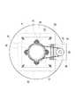
次に、前記液体遠心分離装置1について、図2、図3により説明する。
液体遠心分離装置1は、前記送り配管24からの浄化水を受けて下方に供給する給水部33と、浄化水中の油分を分離除去する遠心分離部35と、該遠心分離部35を回転駆動させるための回転駆動部34と、該回転駆動部34や前記給水部33を上面で支持すると共に前記遠心分離部35で分離された油分と水を一時貯溜する装置本体部36と、これら各構成部33乃至36を支える架台部37とから構成されている。
【0023】
このうち給水部33においては、円筒状で底面に目の小さいメッシュ38aを張設したろ過器38が最上部に配置され、該ろ過器38の下部には、側面視漏斗状の受け槽39が外嵌されている。該受け槽39の外周側面は、平面視く字状の取付部材65を介して4本の支持ステー40の上部内側に締結固定され、該支持ステー40は前記装置本体部36上に立設されており、前記受け槽39とろ過器38とは、液体遠心分離装置1の上部に支持固定できるようにしている。
【0024】
前記受け槽39の下部には、給水管41の上端部が内挿連結され、該給水管41の上下途中部には、上から順に電磁バルブ42と手動バルブ43とが並設されている。これにより、前記送り配管24から圧送されてきた浄化水は、ろ過器38のメッシュ38aでろ過されて金属粉等の細かな異物が除去された後、遠心分離処理の開始終了のタイミングに合わせて、下方の遠心分離部35に自動又は手動で適量だけ供給されるようにしている。
【0025】
また、前記回転駆動部34においては、前記支持ステー40が立設された基板55の中央開口部内に、ハウジング48が内挿固定され、該ハウジング48の内側面には、ボールベアリング等の複数の軸受け69が固設されており、該軸受け69によって回転筒68が水平回動可能に支持されている。
【0026】
該回転筒68の上端部には従動軸49が載置固設され、該従動軸49には従動プーリ50が外嵌されている。一方、前記基板55の外周にあり装置本体部36の上面を基板55と伴に構成する平面視ドーナツ状の蓋板54からは、側面視L字状の取付具47が立設され、該取付具47には、側面視逆L字状の取付プレート75を介して、駆動軸45を上下方向に備えたモータ44が取り付けられている。
【0027】
そして、該駆動軸45には駆動プーリ46が外嵌され、該駆動プーリ46と前記従動プーリ50との間にはベルト51が巻回されており、ベルト51を介して、モータ44からの回転力を前記従動軸49に伝達し、回転筒68を回転させることにより、該回転筒68の下端部に設けた遠心分離部35を、所定の回転速度にて回転駆動可能としているのである。
【0028】
また、前記装置本体部36は、前記給水部33や回転駆動部34を載置する基板55・蓋板54と、該蓋板54から垂設された円筒状の側板52と、該側板52の下端開口部を閉塞する底板70と、該底板70の略中央に立設された円筒状の側板53と、該側板53の内側略中央に配設された回収スイッチ56とから構成される。
【0029】
そして、前記側板53・底板70に囲まれた空間には、遠心分離部35で油分を分離除去した浄化水が流下する水だめ72が形成され、該水だめ72の下部には、前記戻り配管25に連通した戻りパイプ73も配設されており、遠心分離部35で油分を除去した浄化水が、一旦水だめ72に蓄えられた後、戻りパイプ73から戻り配管25を通って前記浄化水槽30内に流入するようにしている。
【0030】
更に、前記側板53と回収スイッチ56外周面と底板70とに囲まれた空間には、遠心分離部35で抽出した油分が流下する油だめ71が形成され、該油だめ71の下部には、排油パイプ74が配設され、該排油パイプ74の下方には廃油タンク60が配設されている。そして、遠心分離処理後に前記回収スイッチ56を作動させると、後述する機構により、遠心分離部35の中央下端部が開放され、遠心力で抽出された油分を、一旦油だめ71に蓄えた後、排油パイプ74から廃油タンク60内に流入することができる。
【0031】
また、前記架台部37においては、前記底板70を上面に載置固定すると共に前記廃油タンク60を内部に載置したフレーム本体61と、該フレーム本体61下部に伸縮可能に螺挿された複数の固定具62と、該固定具62の間に取り付けた複数のキャスタ63・ストッパ付きキャスタ64とから構成される。これにより、固定具62を縮めてキャスタ63・ストッパ付きキャスタ64を作業床76上に接地させた後、液体遠心分離装置1を押して所定位置まで移動し、該所定位置にて固定具62を伸ばしてキャスタ63・ストッパ付きキャスタ64を接地面から浮かせるようにして、液体遠心分離装置1を固定することができ、メンテナンス場所や別洗浄システム設置場所への移動にも迅速に対応することができ、ハンドリングに優れた液体遠心分離装置1を提供することができる。
【0032】
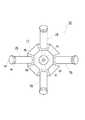
次に、前記遠心分離部35について、図2、図4乃至図6により説明する。
遠心分離部35は、主に、回転により遠心力を発生させる回転体77と、該回転体77の外周に装着される複数の分離ユニット78とから構成される。
【0033】
このうちの回転体77の上部には凹部79が形成され、該凹部79には、前記回転筒68の下端部が上方より嵌合されて図示せぬ締結具で固定されており、回転体77が、前記回転筒68に連結され、モータ44により回転駆動される構成としている。
【0034】
回転体77の回転軸芯上には、主液路80が形成され、該主液路80は、前記回転筒68と従動軸49の回転軸芯上に形成された液路67に連通され、更に、該液路67の上部には、前記給水管41の下端部が内挿されており、前記給水部33からの浄化水が、給水管41、液路67を介して回転体77の主液路80に供給されるようにしている。このような主液路80の上下途中部から回転半径方向外方に向かっては、複数の分岐液路81が延設され、該分岐液路81の先部は、前記分離ユニット78に連通されている。
【0035】
主液路80の下端部は、回転体77の下部に設けた廃油室82に連通され、該廃油室82には、付勢バネ等の弾性体83が内挿されると共に、廃油室82下部の開口部には、蓋体86が覆設されてロックナット87で固定されている。そして、該蓋体86の回転軸芯には、円形開口部88が形成され、該円形開口部88と前記弾性体83との間には、尖端部を下方に向けた円錐状シャッタ84が介設されている。該尖端部は、前記円形開口部88に嵌合される一方、尖端部と反対側の平面は、前記弾性体83の下端に当接されており、この弾性体83の張力により、円錐状シャッタ84は下方の円形開口部88に向かって常に付勢されている。これにより、通常は、円形開口部88は円錐状シャッタ84の尖端部により閉塞され、廃油室82からは液が漏下しないようにしている。
【0036】
該円錐状シャッタ84下方に配置された前記回収スイッチ56は、基台112と、該基台112に固設されたシリンダー57と、該シリンダー57のアーム58と、該アーム58上端に嵌装されたピン59とから構成され、この回収スイッチ56は、前記コントローラを介して前記モータ44に接続されており、回転体77の回転停止後には、シリンダー57を作動させてアーム58を伸ばし、ピン59で円錐状シャッタ84を上方に押し上げるようにしている。逆に、回転体77が回転中は、アーム58を縮めて、弾性体83の張力により円錐状シャッタ84で、前記円形開口部88を閉塞するようにしている。
【0037】
また、前記分離ユニット78は、円筒状の分離容器89と、浄化液を重液にあたる水と軽液にあたる油分とに仕切るための仕切部90とから構成される。このうちの分離容器89で回転体77に近い方の端部には、固定板89aが外嵌固定され、該固定板89aは、回転体77の外周側面85に複数のボルト96で締結されており、分離容器89は回転体77に着脱可能に取り付けられ、分離容器89のメンテナンスや部品交換が容易に行えるようにしている。
【0038】
分離容器89で回転体77から遠い方の端部には、こし網92が充填され、該こし網92の外側はパンチメタル93で覆われると共に、該パンチメタル93の上から、蓋体94が覆設されてロックナット95で分離容器89に固定されている。更に、分離容器89で回転体77から遠い方の端部の下部には、排水パイプ100が設けられ、該排水パイプ100下端には自動排液装置91が設けられている。なお、分離容器89は、回転半径方向で外方が内方よりも低い傾斜姿勢となるように取り付けられており、分離された水が前記排水パイプ100内に流入しやすくしている。
【0039】
ここで、前記自動排液装置91の構成について説明する。
図4、図6に示すように、前記排水パイプ100の下部には、排水パイプ100内の液路100aと直交するように、自動排液装置91のピン97が内挿されている。該ピン97で回転体77から遠い方の端部には、キャップ付きロックナット98が螺嵌されると共に、ピン97で回転体77に近い方の端部には、バネ止め97aが設けられ、該バネ止め97aと排水パイプ100側面との間のピン97上には、付勢バネ等の弾性体99が外嵌されており、通常は、図6(b)に示すように、ピン97が、回転体77に向かって(図では右側に)摺動するように付勢されている。更に、該ピン97内にも、前記液路100aと平行に液路97bが形成されている。
【0040】
このような構成において、回転速度が遅かったり回転が停止していて遠心分離に必要な大きさの遠心力(以下「分離遠心力」とする)が作用していない場合には、図6(b)に示すように、ピン97が回転体77に向かって(図では右側に)摺動し、液路97bと液路100aとが重なって一本の排水路を形成して、分離容器89中の液が、液路100a・97bを通って排出される。逆に、分離ユニット78を回転して分離遠心力を作用させると、該分離遠心力により、図6(a)に示すように、ピン97は回転体77から遠ざかる方向(図では左側)に摺動し、液路97bは液路100aからずれて液路100aをピン97が閉塞する状態となり、分離容器89中の液が排出されなくなる。このため、遠心分離処理中は、分離された液は分離容器89内に貯溜されたままであり、遠心分離処理終了後には、自動的に排水パイプ100から排出・流下される。
【0041】
すなわち、前記分離容器89には、遠心力の増減に応じて開閉する自動排液装置91を設けるので、遠心分離処理終了の度に前記蓋体94を取り外したりして、手作業で分離した液を回収する必要がなく、回収作業の自動化を進めることができ、遠心分離処理全体の処理効率を向上させることができるのである。
【0042】
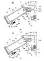
次に、前記仕切部90について、図2,図4乃至図6により説明する。
図6に示すように、前記回転体77の外周部で前記分岐液路81の延長上には装着室101が設けられ、該装着室101に前記仕切部90が内装されている。そして、該仕切部90は、先部を絞って前記装着室101に外方より嵌入した筒状の注入部材102と、該注入部材102に外側から内挿された鋼球等の球状体104と、同じく注入部材102の外端に係止したバネ止め106と、該バネ止め106と前記球状体104との間に介設された付勢バネ等の弾性体105と、注入部材102の外端に内挿固定されたパイプ103とから構成されている。
【0043】
このうちの注入部材102で回転半径方向の内側端部には、供給液路109が形成され、該供給液路109の入口は、前記分岐液路81に連通されると共に、供給液路109の出口には、凹部110が形成されている。そして、該凹部110には、前記球状体104が嵌合され、該球状体104は、前記弾性体105の張力により回転体77側に向かって常に付勢されている。これにより、通常は、図6(b)に示すように、供給液路109は球状体104により閉塞されており、分岐液路81からは、液が仕切部90内に流入しないようにしている。なお、このように、閉塞体として球状体104を用いた仕切部を、以下、球タイプ仕切部とする。
【0044】
このような構成において、所定の回転数まで遠心分離部35を回転させると、図6(a)に示すように、分離遠心力が球状体104に作用するため、該球状体104は、弾性体105の張力に打ち勝って回転体77から遠ざかる方向(図では左側)に移動して前記凹部110から離間し、供給液路109が注入部材102の内部空間に連通された状態となる。同時に、主液路80内の浄化水107のうち、大部分の容積を占める水(重液)107aは、該水107a中に粒子となって分散している油分(軽液)107bを残して、その比重差から、回転半径方向外方に向かって流動していき、主液路80内から分岐液路81内に移動し、更に、前記供給液路109を通って注入部材102の内部空間に流入するのである。
【0045】
該内部空間に流入した水107aは、球状体104等と注入部材102内壁との隙間を流れ、前記ガイドパイプ103を通って、分離容器89内に流下する。この際、前述したように、分離容器89に設けた自動排液装置91の液路100aは閉塞状態にあるため、分離容器89内には水107aが次第に蓄積されていく。一方、前記蓋体86の円形開口部88も閉塞状態にあるため、前記主液路80・分岐液路81・排油室82内には後に残された油分107bが次第に蓄積されていく。
【0046】
そして、遠心分離処理を完了した後、回転速度を減少させていくと、図6(b)に示すように、球状体104に作用する遠心力が分離遠心力を下回り、弾性体105の張力が遠心力を上回るようになるため、球状体104は、弾性体105に押圧されて回転体77に向かって(図では右側に)移動し、前記凹部110に嵌合して供給液路109が閉塞される。
【0047】
この際、前述したように、分離容器89に設けた自動排液装置91の液路100aは開状態にあるため、水107aが分離容器89内から前記水だめ72内に流下し回収される。一方、前述の如く、回転体77の回転停止後は、円錐状シャッタ84がピン59によって押し上げられるため、前記蓋体86の円形開口部88が開状態となり、油分107bは、排油室82から円錐状シャッタ84の周囲を通って前記油だめ71内に流下し回収される。
【0048】
このようにして、遠心分離処理中に、仕切部90を境にして、水107aは回転半径方向外方に、油分107bは回転半径方向内方に分離され、遠心分離処理後には、自動的に水だめ72や油だめ71に流下・回収されるのである。
【0049】
すなわち、回転により遠心力を発生する回転体77と、該回転体77に装着する分離ユニット78とを備えると共に、該分離ユニット78内にて、比重の異なる二種の液体から成る混合液である浄化水107を、遠心力により各液体に分離する液体遠心分離装置1において、前記分離ユニット78には、回転中に液体を貯溜する分離容器89と、比重の小さい軽液である油分107bと比重の大きい重液である水107aとを回転半径方向の内外に分ける仕切部90とを設け、該仕切部90は所定の大きさの遠心力が作用すると内外連通状態に移行可能な構成とし、混合液である浄化水107中の重液である水107aが、軽液である油分107bと層状に分離することなく、前記仕切部90を介して分離容器89内に流動可能としたので、遠心分離処理において、従来は別々に行っていた、混合液を各液毎に多層に分ける分離作業と、この分離した各層液をそれぞれ回収する抽出作業とを、回転中の混合液内で同時に行うことができ、従来は回転停止後又は回転停止間際に手動又は自動で別途に行っていた抽出作業そのものを省略できるため、抽出作業時の液流による層液間の相互汚染を確実に防止することができ、液体分離性能が向上する。更に、処理効率が向上して遠心分離処理全体の自動化が可能となり、小型軽量型の液体遠心分離装置1を洗浄システム2内に組み込むことができ、別施設にわざわざ運搬して行っていた浄化処理にかかるコストや手間を、大幅に軽減することができるのである。
【0050】
また、前記仕切部90は、混合液である浄化水107を分離ユニット78に流入させるための供給液路109を設けた注入部材102と、供給液路109の出口を塞ぐ閉塞体である球状体104と、該閉塞体である球状体104を前記出口に向かって押圧する弾性体105とから構成し、所定の大きさの遠心力が作用すると閉塞体である球状体104が出口から離間して、混合液である浄化水107中の重液である水107aが出口から仕切部90の外側に流動する構成としたので、仕切部の内外連通状態への移行手段として、弾性力と遠心力の釣り合いで伸縮する閉塞体を利用できるため、複雑な連通装置を別途設ける必要がなく、部品点数の削減による装置コストの低減、及びメンテナンス性の向上を図ることができる。
【0051】
加えて、以上のように、前記閉塞体は、供給液路109の出口が開いた凹部110に嵌合可能な球状体104であるので、回転中又は回転停止後に該球状体104に作用する弾性力や遠心力の方向が、供給液路109の出口に対して一定しなくても、球状体104は凹部110に隙間なく嵌合できるため、供給液路109の出口をきっちりと閉塞することができ、軽液である油分107bによる、比重の大きい重液である水107aの再汚染を確実に防止できるのである。
【0052】
次に、前記仕切部90の別形態について、図6乃至図11により説明する。
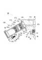
まず、前述のような球状体104の代わりに板状体を用いた仕切部(以下、「板タイプ仕切部」とする)114について説明する。
図6、図7に示すように、該板タイプ仕切部114は、分離ユニット119の分離容器89内で回転体120に近い方の端部近傍に内設されており、複数の供給油路115aを有し外周面が分離容器89内壁に水密に固設される円板状の注入部材115と、該注入部材115の外側面に密着すると共に外周面が分離容器89内壁に水密摺動可能に内挿される板状体116と、分離容器89内壁に設けたバネ止め118と、該バネ止め118と前記板状体116との間に開設された付勢バネ等の弾性体117とから構成される。
【0053】
このうちの板状体116には、注入部材115に密着時に供給液路115aの出口と重ならない位置に、連通孔116aが設けられる。更に、板状体116は、前記バネ止め118に一端を係止した前記弾性体117の他端に固定され、該弾性体117の張力により、回転体120側に向かって常に付勢されている。これにより、通常は、図7(a)に示すように、供給液路115aは板状体116により閉塞されており、分岐液路81aからは、液が板タイプ仕切部114内に流入しないようにしている。なお、分岐液路81aは、前記球タイプ仕切部90の分岐液路81に比べ、装着室101が設けられていない分だけ長く延設して、主液路80が分離容器89内に連通可能としている。
【0054】
このような構成において、所定の回転数まで遠心分離部35を回転させると、図7(a)に示すように、分離遠心力が板状体116に作用するため、該板状体116は、弾性体117の張力に打ち勝って回転体120から遠ざかる方向(図では左側)に移動して注入部材115から離間し、供給液路115aが仕切部114の内部に連通された状態となる。同時に、主液路80内の水107aは、該水107a中に粒子となって分散している油分107bを残して、その比重差から、回転半径方向外方に向かって流動していき、主液路80内から分岐液路81a内に移動し、更に、前記供給液路115aを通って仕切部114内に流入する。
【0055】
流入した水107aは、注入部材115と板状体116との間を流れ、連通孔116aから弾性体117を通って分離容器89内に流下する。この際、前記球タイプ仕切部90と同様に、分離容器89の排水パイプ100と、排油室82の円形開口部88とは、いずれも閉塞状態にあるため、水107aと油分107bとは、遠心分離部35内の別位置に次第に蓄積されていく。
【0056】
そして、遠心分離処理を完了した後、回転速度を減少させていくと、図7(b)に示すように、板状体116に作用する遠心力が分離遠心力を下回り、弾性体117の張力が遠心力を上回るようになるため、板状体116は、弾性体117に押圧されて回転体120に向かって(図では右側に)摺動し、注入部材115に密着して供給液路115aが閉塞される。この際、前記球タイプ仕切部90と同様に、分離容器89の排水パイプ100と、排油室82の円形開口部88とは、いずれも開状態になるため、水107aと油分107bとは遠心分離部35内から自動的に水だめ72や油だめ71に流下し回収されるのである。
【0057】
しかも、このような板タイプ仕切部114の場合には、供給液路115aや連通孔116aの断面積、形状、個数、開口位置等を種々変更することにより、水107aが板タイプ仕切部114中を流れる際の液流を細かく調整することができる。
【0058】
すなわち、前記閉塞体は、注入部材115の外側面に密着可能な板状体116であり、該板状体116には、密着時に供給液路115aの出口と重ならない位置に連通孔116aを設けるので、供給液路115aや連通孔116aの開口条件の変更により仕切部114中の液流を微調整して、軽液である油分107bの存在比率、分散状態、粘性、比重や、異物の混入状況等に応じて液流の最適化を図ることができ、重液である水107aを選択的に分離容器89内へ流入させ、液体分離性能の一層の向上を図ることができる。
【0059】
続いて、前記板タイプ仕切部114を回転半径方向に複数並べた並設タイプの仕切部について説明する。なお、本実施例では、板タイプについてのみ説明するが、前記球タイプ仕切部90を回転半径方向に複数並べた場合についても、その作用・効果は同様である。
【0060】
図8に示すように、並設板タイプ仕切部121は、分離ユニット130の分離容器89内で回転体120に近い方から順に第1仕切りユニット121aと第2仕切りユニット121aとが内設され、該第1仕切りユニット121aと第2仕切りユニット121aとの間の空間には中間液だめ131が形成されている。そして、いずれの仕切りユニット121a・121bも、前述の板タイプ仕切部114と同様に、供給液路122a・126aを設けた注入部材122・126、連通孔123a・127aを設けた板状体123・127、弾性体124・128、及びバネ止め125・129から構成される。
【0061】
このような構成においては、所定の回転数まで遠心分離部35を回転させると、仕切りユニット121a・121bがほぼ同時に連通状態に移行するように、前記弾性体124・128の弾性係数や板状体123・127の重量等を調節した場合には、前記分岐液路81aから遠心力により流動してきた水107aは、第1仕切りユニット121a内を通って前記中間液だめ131に流入し、そこで一旦流速が落ちた後、更に、第2仕切りユニット121b内を通って本液だめ132に流入する。これにより、たとえ油分107bが、第1仕切りユニット121aに至るまでに分離しきれずに水107a中に残留していても、流速の落ちる中間液だめ131において更に遠心力を受けて再分離され、該中間液だめ131に回収される。
【0062】
また、所定の回転数まで遠心分離部35の回転数を徐々に増加させると、初めに第1仕切りユニット121aが連通状態に移行し続いて第2仕切りユニット121bが連通状態に移行するように調節した場合には、前記分岐液路81aから遠心力により流動してきた水107aは、第1仕切りユニット121a内を通って前記中間液だめ131に流入し、そこに一旦貯溜された後、しばらくしてから連通状態になった第2仕切りユニット121b内を通って本液だめ132に流入する。これにより、たとえ水107aとの比重差が小さかったり微細に分散していて分離が困難な油分107bであっても、該油分107bは、中間液だめ131内でほぼ静止状態で遠心力を受けて再分離が十分に進むため、中間液だめ131にほとんどが回収されることとなる。
【0063】
すなわち、前記仕切部は、回転半径方向に中間液だめ131を介して複数の仕切りユニット121a・121bを並設するので、該中間液だめ131において、低速又は静止した状態にて重液である水107aに遠心力を作用させることができるため、重液である水107aとの比重差が小さかったり微細に分散して分離できずに残っていた軽液である油分107bまでも確実に分離でき、液体分離性能を向上することができるのである。
【0064】
続いて、堰状体133を用いた仕切部(以下、「堰タイプ仕切部」とする)137について説明する。
図9、図10に示すように、該堰タイプ仕切部137においては、分離ユニット135の角筒状の分離容器134内で回転体120に近い底板134a上に、堰状体133が載置され、該堰状体133は、底板134a上にボルト等の複数の締結部材136によって締結固定される。そして、該堰状体133は、回転体120に近い方から順に、前記分岐液路81aの出口下面と略同一高さにある平坦な導入部133aと、該導入部133aから徐々に立ち上がり、滑らかな逆U字状の曲線を描いた後に、徐々に下降する凸部133bと、該凸部133bから分離容器134の底板134aに向かって一定の傾きで傾斜する流下部133cとから構成される。
【0065】
このような構成において、所定の回転数まで遠心分離部35を回転させると、図10(a)に示すように、水107aが、大部分の油分107bを主液路80内に残したまま、遠心力により回転半径方向外方に向かって流動して、前記導入部133aに到達する。そして、前記凸部133bの手前で一旦流速が落ちた後、遠心力が大きい重液である水107aが、堰状体133に至るまでに分離しきれずに残留していた油分107bに優先して、凸部133bを乗り越え、流下部133cを流れ落ちるのである。
【0066】
そして、遠心分離処理を完了した後、回転速度を減少させていくと、図10(b)に示すように、堰状体133の外方には、より清浄化の進んだ水107aが蓄えられる一方、堰状体133の内方には、凸部133bを乗り越えられなかった油分107bが濃縮されて蓄えられる。この際、前述の如く、分離容器134の排水パイプ100と、排油室82の円形開口部88とは、いずれも開状態になるため、水107aと油分107bとは遠心分離部35内から自動的に前記水だめ72や油だめ71に流下し回収される。
【0067】
すなわち、前記仕切部は、分離容器の入口下部に設けた堰状体133から構成し、所定の大きさの遠心力が作用すると、混合液中の重液である水107aが、該堰状体133を乗り越えて回転半径方向外方に優先的に流動するので、堰状体133の手前において、重液である水107aに遠心力を作用させて軽液である油分107bの再分離を行うことができるため、液体分離性能を一層向上できる。更に、堰状体133は構造が単純であり、部品数削減による部品コストの低減やメンテナンス性の向上も図ることができるのである。
【0068】
続いて、前記凸部133bを回転半径方向に二個並べた堰状体から成る二山堰タイプの仕切部について説明する。
図11に示すように、二山堰タイプ仕切部138の堰状体139も、分離ユニット140の角筒状の分離容器134内で回転体120に近い底板134a上に載置され、ボルト等の複数の締結部材136によって締結固定される。そして、該堰状体139は、回転体120に近い方から順に、前記分岐液路81aの出口下面と略同一高さにある平坦な導入部139aと、該導入部139aから徐々に立ち上がり、滑らかな逆U字状の曲線を描いた後に、徐々に下降する第1凸部139bと、該第1凸部139bに隣接し側面視で略同一形状の第2凸部139dと、該第2凸部139dと前記第1凸部139bとの間に設けた凹状の中間液だめ139cと、前記第2凸部139dから分離容器134の底板134aに向かって一定の傾きで傾斜する流下部139eとから構成される。
【0069】
このような構成において、所定の回転数まで遠心分離部35を回転させると、水107aが、大部分の油分107bを主液路80内に残したまま、遠心力により回転半径方向外方に向かって流動して、前記導入部139aに到達する。そして、前記第1凸部139bの手前で一旦流速が落ちた後、遠心力が大きい重液である水107aが、堰状体139に至るまでに分離しきれずに残留していた油分107bに優先して、第1凸部139bを乗り越えて中間液だめ139cに流入し、一旦貯溜される。そして、この水107aは、該中間液だめ139cにおいても遠心力を受け、次の第2凸部139dを乗り越え、流下部139eを流れ落ちる。すると、たとえ油分107bが、第1凸部139bでは十分に分離しきれずに水107a中に残留していても、中間液だめ139cにおいて更に長時間にわたり遠心力を受けて十分に再分離され、中間液だめ139cに回収されるのである。
【0070】
すなわち、前記堰状体139は、回転半径方向に中間液だめ139cを有する複数の凸部139b・139dから構成するので、該中間液だめ139cにおいて、低速又は静止した状態にて重液である水107aに遠心力を作用させることができるため、最初の凸部139bを乗り越えても分離されずに残っていた微量の軽液である油分107bまでも、確実に分離することができ、液体分離性能を更に一層向上させることができる。
【0071】
なお、本実施例では、堰状体の凸部は、2個としているが、3個以上設け、その間に複数の中間液だめを形成してもよく、特に限定されない。この場合、油分107bを堰状体で多段階に渡って回収できるため、遠心分離処理された水107aの純度を一層高くすることができる。
【0072】
以上のような構成から成る液体遠心分離装置1において、種々の液体からなる混合液について調査した結果、前記分離ユニット78・119・130・135・140と回転体77・120の回転速度は1000〜10000rpmの範囲が好ましい。回転速度が1000rpm未満では、作用する遠心力が小さすぎて、重液が軽液よりも優先的に流動することが困難となる。しかも、閉塞体である球状体104や板状体116が、弾性体105・117の張力に抗して移動したり、重液が、堰状体133・139を乗り越えにくくなり、仕切部90・114・121・137・138自体が安定した機能を発揮できない。逆に、回転速度が10000rpm越えでは、遠心力が大きすぎて、軽液までが重液と一緒に高速で回転半径方向外方に流動するため、液体分離ができない。
【0073】
すなわち、分離ユニット78・119・130・135・140と回転体77・120の回転速度は、1000〜10000rpmであるので、適正な大きさの遠心力により、仕切部90・114・121・137・138を安定して機能させると共に、重液を軽液よりも優先的に流動させることができ、常時、十分な液体分離性能を確保することができる。
【0074】
なお、以上の実施例では、油分の混入した洗浄水から洗浄水のみを分離・回収する場合について説明しているが、本発明は、金属の切削加工に広く使用される切削液の分離・回収にも適用可能であり、特に限定されるものではない。
【0075】
【発明の効果】
本発明は、以上のように構成したので、以下に示す効果を奏する。
すなわち、請求項1においては、回転により遠心力を発生する回転体と、該回転体に装着する分離ユニットとを備えると共に、該分離ユニット内にて、比重の異なる二種の液体から成る混合液を、遠心力により各液体に分離する液体遠心分離装置において、前記分離ユニットには、回転中に液体を貯溜する分離容器と、比重の小さい軽液と比重の大きい重液とを回転半径方向の内外に分ける仕切部とを設け、該仕切部は所定の大きさの遠心力が作用すると内外連通状態に移行可能な構成とし、混合液中の重液が、軽液と層状に分離することなく分散状態のままで、前記仕切部を介して分離容器内に流動可能としたので、遠心分離処理において、従来は別々に行っていた、混合液を各液毎に多層に分ける分離作業と、この分離した各層液をそれぞれ回収する抽出作業とを、回転中の混合液内で同時に行うことができ、従来は回転停止後又は回転停止間際に手動又は自動で別途に行っていた抽出作業そのものを省略できるため、抽出作業時の液流による層液間の相互汚染を確実に防止することができ、液体分離性能が向上する。更に、処理効率が向上して遠心分離処理全体の自動化が可能となり、小型軽量型の液体遠心分離装置1を洗浄システム2内に組み込むことができ、別施設にわざわざ運搬して行っていた浄化処理にかかるコストや手間を、大幅に軽減することができるのである。
【0076】
請求項2においては、請求項1記載の仕切部は、混合液を分離ユニットに流入させるための供給液路を設けた注入部材と、供給液路の出口を塞ぐ閉塞体と、該閉塞体を前記出口に向かって押圧する弾性体とから構成し、所定の大きさの遠心力が作用すると閉塞体が出口から離間して、混合液中の重液が出口から仕切部の外側に流動する構成としたので、仕切部の内外連通状態への移行手段として、弾性力と遠心力の釣り合いで伸縮する閉塞体を利用できるため、複雑な連通装置を別途設ける必要がなく、部品点数の削減による装置コストの低減、及びメンテナンス性の向上を図ることができる。
【0077】
請求項3において、請求項2記載の仕切部は、回転半径方向に中間液だめを介して複数並設するので、該中間液だめにおいて、低速又は静止した状態にて重液に遠心力を作用させることができるため、重液との比重差が小さかったり微細に分散して分離できずに残っていた軽液までも確実に分離でき、液体分離性能を向上できる。
【0078】
請求項4においては、請求項2又は請求項3記載の閉塞体は、供給液路の出口が開いた凹部に嵌合可能な球状体であるので、回転中又は回転停止後に該球状体に作用する弾性力や遠心力の方向が、供給液路の出口に対して一定しなくても、球状体は凹部に隙間なく嵌合できるため、供給液路の出口をきっちりと閉塞することができ、軽液による重液の再汚染を確実に防止できる。
【0079】
請求項5においては、請求項2又は請求項3記載の閉塞体は、注入部材の外側面に密着可能な板状体であり、該板状体には、密着時に供給液路の出口と重ならない位置に連通孔を設けるので、供給液路や連通孔の開口条件の変更により仕切部中の液流を微調整して、軽液の存在比率、分散状態、粘性、比重や、異物の混入状況等に応じて液流の最適化を図ることができ、重液を選択的に分離容器内へ流入させ、液体分離性能の一層の向上を図ることができる。
【0080】
請求項6においては、請求項1記載の仕切部は、分離容器の入口下部に設けた堰状体から構成し、所定の大きさの遠心力が作用すると、混合液中の重液が、該堰状体を乗り越えて回転半径方向外方に優先的に流動するので、堰状体の手前において、重液に遠心力を作用させて軽液の再分離を行うことができるため、液体分離性能を一層向上できる。更に、堰状体は構造が単純であり、部品数削減による部品コストの低減やメンテナンス性の向上も図ることができるのである。
【0081】
請求項7においては、請求項6記載の堰状体は、回転半径方向に中間液だめを有する複数の凸部から構成するので、該中間液だめにおいて、低速又は静止した状態で重液に遠心力を作用させることができるため、最初の凸部を乗り越えても分離されずに残っていた微量の軽液までも、確実に分離することができ、液体分離性能を更に一層向上させることができる。
【0082】
請求項8においては、請求項1乃至請求項7のいずれか一項に記載の分離容器には、遠心力の増減に応じて開閉する排出装置を設けるので、遠心分離処理終了の度に手作業で分離した液を回収する必要がなく、回収作業の自動化を進めることができ、遠心分離処理全体の処理効率を向上させることができる。
【0083】
請求項9においては、請求項1乃至請求項8のいずれか一項に記載の分離ユニットと回転体の回転速度は、1000〜10000rpmであるので、適正な大きさの遠心力により、仕切部を安定して機能させると共に、重液を軽液よりも優先的に流動させることができ、常時、十分な液体分離性能を確保することができるのである。
【図面の簡単な説明】
【図1】本発明の液体遠心分離装置を組み込んだ洗浄システムの概略構成図である。
【図2】本発明の液体遠心分離装置の側面一部断面図である。
【図3】同じく平面図である。
【図4】遠心分離部の側面一部断面図である。
【図5】同じく底面図である。
【図6】球タイプ仕切部による液体遠心分離構成を示し、図6(a)は遠心分離中の球タイプ仕切部の側面一部断面図、図6(b)は遠心分離終了後の球タイプ仕切部の側面一部断面図である。
【図7】板タイプ仕切部による液体遠心分離構成を示し、図7(a)は遠心分離中の板タイプ仕切部の側面一部断面図、図7(b)は遠心分離終了後の板タイプ仕切部の側面一部断面図である。
【図8】遠心分離終了後の並設板タイプ仕切部の側面一部断面図である。
【図9】堰タイプ仕切部の正面一部断面図である。
【図10】堰タイプ仕切部による液体遠心分離構成を示し、図10(a)は遠心分離中の堰タイプ仕切部の側面一部断面図、図10(b)は遠心分離終了後の堰タイプ仕切部の側面一部断面図である。
【図11】遠心分離終了後の二山堰タイプ仕切部の側面一部断面図である。
【符号の説明】
1 液体遠心分離装置
77・120 回転体
78・119・130・135・140 分離ユニット
89・134 分離容器
90・114・121・121a・121b・137・138 仕切部
91 自動排液装置
102・115 注入部材
104 球状体
105・117・124・128 弾性体
107 混合液
107a 重液
107b 軽液
109・115a 供給液路
110 凹部
116 板状体
116a 連通孔
131・139c 中間液だめ
133・139 堰状体
139b・139d 凸部[0001]
BACKGROUND OF THE INVENTION
The present invention relates to a liquid centrifuge that separates a mixture of two kinds of liquids that do not dissolve in each other by a difference in specific gravity using centrifugal force, and in particular, a large amount of oil immediately after washing a machined product. This invention relates to a liquid centrifuge that purifies and reuses the cleaning water (hereinafter referred to as “contaminated water”) contained in the water without purifying it to a purity close to that of the original cleaning water.
[0002]
[Prior art]
Conventionally, oil components such as rust preventive oil and lubricating oil adhering to machined metal products are continuously sprayed on the metal products after processing by adding wash water with additives such as triethanolamine to water. However, since the washing water gradually emulsifies and detergency decreases when these oil components are mixed, it is necessary to periodically remove the oil components.
[0003]
In order to separate and remove only oil from contaminated water mixed with such moisture and oil, it is generally left to stand until both of them naturally separate due to the difference in specific gravity, and a natural standing treatment is performed to collect and remove the floating oil. However, when the specific gravity difference is small or the particle size is small, the separation is insufficient, it takes a long time, and a large area is required to leave it to stand. Therefore, it is necessary to process a large amount of contaminated water at a time from the viewpoint of efficiency, and enormous purification costs are incurred at a time. Furthermore, a large amount of water is required to store a large amount of contaminated water until the next treatment. Storage facilities, maintenance costs and manpower are required, and in addition, there is a problem of deterioration of the working environment and environmental pollution due to the odor and leakage of contaminated water associated with long-term storage.
[0004]
In order to solve this, it is conceivable to apply a centrifugal separation process capable of separating a liquid in a mixed state in a short time by using a rotating centrifugal force. Industrial scale liquid centrifuges include cylindrical and separator plate type centrifugal settling machines, both of which are intended for the treatment of a large amount of liquid mixture and have a large rotating body with heavy weight. In addition to being expensive, maintenance requires great care, and for removing oil from contaminated water, a liquid centrifuge that is compact and lightweight and can be placed close to a metal processing line. The device is suitable.
[0005]
In such a small and light liquid centrifuge, a centrifugal separation container is mounted around the rotating body, and contaminated water is put into the separation container and rotated, so that the specific gravity like oil is reduced. Known to be separated into an upper layer liquid composed of a light liquid (hereinafter referred to as “light liquid”) and a lower layer liquid composed of a liquid having a higher specific gravity such as water (hereinafter referred to as “heavy liquid”). ing. Each separated layer liquid is sucked out using a suction nozzle such as a syringe or a hole pipettor and extracted to the outside, but this extraction operation accurately grasps the interface position of the layers so that each layer liquid does not mix. It is necessary to perform the process carefully so as not to generate a liquid flow, which is very troublesome and greatly contributes to a decrease in the processing efficiency of the entire centrifugation process.
[0006]
Therefore, in order to simplify the extraction operation and increase the processing efficiency of the centrifugal separation process, the separation container has a double structure of the main body and the inner cylinder, and the upper layer formed by centrifugation between the inner surface of the main body and the outer surface of the inner cylinder. From among the liquid and the lower layer liquid, a technique for sucking and extracting only the lower layer liquid from the lower end of the inner cylinder (see, for example, Patent Document 1), and a separation member that partitions the inside of the separation container into an upper container and a lower container, The buoyancy of the separation member can be adjusted in accordance with the increase or decrease of centrifugal force, and the separation member that floats and sinks is formed by centrifugation in the upper container by opening and closing the upper and lower communication paths between the upper container and the lower container as appropriate. A technique (for example, refer to Patent Document 2) in which only the lower layer liquid is caused to flow down to the lower container through the upper and lower communication paths from the upper layer liquid and the lower layer liquid that have been extracted is known.
[0007]
[Patent Document 1]
JP-A-9-285740
[Patent Document 2]
JP 2000-70763 A
[0008]
[Problems to be solved by the invention]
However, since the former technique requires a suction nozzle for extraction as in the conventional case, if there is a slight error in the position of the tip of the suction nozzle during suction, the tip is in contact with the bottom of the separation container and cannot be sucked. However, it is difficult to automate the extraction work, but it cannot be expected to significantly improve the processing efficiency of the centrifugal separation process. .
In the latter technique, the structure of the separating member is complicated, and it is very difficult to adjust the buoyancy. Therefore, like contaminated water after washing a machined product, it is like sludge consisting of chips. In a mixed liquid containing foreign matter, the foreign matter adheres to or enters the separation member, causing the gravity and buoyancy of the separation member to fluctuate violently. However, there was a problem that even the upper layer liquid flows down together with the lower layer liquid and the lower layer liquid is contaminated.
[0009]
[Means for Solving the Problems]
The problem to be solved by the present invention is as described above. Next, means for solving the problem will be described.
That is, according to claim 1, the liquid mixture includes a rotating body that generates a centrifugal force by rotation and a separation unit attached to the rotating body, and includes two kinds of liquids having different specific gravities in the separation unit. In the liquid centrifuge that separates the liquid into individual liquids by centrifugal force, the separation unit includes a separation container that stores liquid during rotation, a light liquid having a small specific gravity, and a heavy liquid having a large specific gravity in a rotational radial direction. A partition part that divides the inside and outside is provided, and the partition part is configured to be able to shift to an internal / external communication state when a centrifugal force of a predetermined magnitude acts, so that the heavy liquid in the mixed liquid does not separate into a layered form from the light liquid In the dispersed state, it can flow into the separation container through the partition.
According to a second aspect of the present invention, the partition portion includes an injection member provided with a supply liquid path for allowing the mixed liquid to flow into the separation unit, a closed body that closes an outlet of the supply liquid path, and the closed body toward the outlet. And the elastic body that presses, and when a centrifugal force of a predetermined magnitude acts, the closing body is separated from the outlet, and the heavy liquid in the mixed liquid flows from the outlet to the outside of the partition part. is there.
According to a third aspect of the present invention, a plurality of the partitioning portions are arranged side by side in the rotational radius direction via an intermediate liquid reservoir.
According to a fourth aspect of the present invention, the closing body is a spherical body that can be fitted into a recess in which an outlet of the supply liquid passage is opened.
In
According to a sixth aspect of the present invention, the partition portion is composed of a weir-like body provided at the lower part of the inlet of the separation container, and when a centrifugal force of a predetermined size acts, the heavy liquid in the mixed solution It overcomes and flows preferentially outward in the radial direction of rotation.
According to a seventh aspect of the present invention, the weir-like body is composed of a plurality of convex portions having an intermediate liquid reservoir in the rotational radius direction.
According to an eighth aspect of the present invention, the separation container is provided with a discharge device that opens and closes according to increase or decrease of centrifugal force.
According to a ninth aspect of the present invention, the rotation speed of the separation unit and the rotating body is 1000 to 10,000 rpm.
[0010]
DETAILED DESCRIPTION OF THE INVENTION
Next, examples of the present invention will be described.
FIG. 1 is a schematic configuration diagram of a washing system incorporating the liquid centrifuge of the present invention, FIG. 2 is a partial sectional side view of the liquid centrifuge of the present invention, FIG. 3 is a plan view, and FIG. 5 is a bottom view, FIG. 6 shows a liquid centrifugal separation configuration with a sphere-type partition, and FIG. 6 (a) is a partial cross-sectional view of the sphere-type partition during centrifugation. FIG. 6 (b) is a partial cross-sectional side view of the sphere-type partition after centrifugation, FIG. 7 shows a liquid centrifugal separation configuration by the plate-type partition, and FIG. 7 (a) is a plate-type partition during centrifugation. 7 (b) is a partial sectional side view of the plate-type partition after the end of the centrifugation, and FIG. 8 is a partial partial sectional view of the side-by-side plate-type partition after the end of the centrifugation. FIG. 9 is a partial cross-sectional view of the front surface of the weir type partition, and FIG. 10 shows a liquid centrifugal separation configuration by the weir type partition. FIG. 10 (a) is a partial cross-sectional side view of the weir-type partition during centrifugation, FIG. 10 (b) is a partial cross-sectional side view of the weir-type partition after centrifugation, and FIG. 11 is the end of centrifugation. It is side surface partial sectional drawing of a back double dam type partition part.
[0011]
First, the whole structure of the washing |
The
[0012]
The
[0013]
The cleaning
[0014]
In such a configuration, the cleaning
[0015]
Further, in the contaminated
[0016]
In the liquid
[0017]
In such a configuration, when the contaminated water from the contaminated
[0018]
Furthermore, due to evaporation and leakage in the
[0019]
The
[0020]
Purified water from which most of the foreign matter such as oil and sludge has been removed through the primary recovery to the fourth recovery as described above is a cleaning pipe extended from the purified
[0021]
If the amount of contaminated water or purified water increases too much, each water is discharged by
[0022]
Next, the liquid centrifuge 1 will be described with reference to FIGS.
The liquid centrifugal separator 1 receives a purified water from the
[0023]
Among them, in the
[0024]
An upper end portion of the
[0025]
Further, in the
[0026]
A driven
[0027]
A
[0028]
The apparatus
[0029]
In the space surrounded by the
[0030]
Further, in a space surrounded by the
[0031]
In the
[0032]
Next, the
The
[0033]
A
[0034]
A main
[0035]
The lower end portion of the
[0036]
The
[0037]
The
[0038]
The end of the
[0039]
Here, the configuration of the automatic
As shown in FIGS. 4 and 6, a
[0040]
In such a configuration, when the rotation speed is slow or the rotation is stopped and a centrifugal force having a magnitude necessary for centrifugation (hereinafter referred to as “separation centrifugal force”) is not acting, FIG. ), The
[0041]
That is, the
[0042]
Next, the
As shown in FIG. 6, a mounting
[0043]
A
[0044]
In such a configuration, when the
[0045]
The
[0046]
Then, after the centrifugal separation process is completed, when the rotational speed is decreased, the centrifugal force acting on the
[0047]
At this time, as described above, since the
[0048]
In this way, during the centrifugal separation process, the
[0049]
That is, the liquid mixture includes a
[0050]
In addition, the
[0051]
In addition, as described above, since the closed body is the
[0052]
Next, another embodiment of the
First, a description will be given of a partition portion (hereinafter referred to as “plate type partition portion”) 114 using a plate-like body instead of the
As shown in FIGS. 6 and 7, the
[0053]
Of these, the plate-
[0054]
In such a configuration, when the
[0055]
The
[0056]
Then, after the centrifugal separation process is completed, when the rotational speed is decreased, the centrifugal force acting on the plate-
[0057]
In addition, in the case of such a
[0058]
That is, the closing body is a plate-
[0059]
Next, a side-by-side type partition unit in which a plurality of the plate
[0060]
As shown in FIG. 8, the juxtaposed
[0061]
In such a configuration, the elastic coefficients of the
[0062]
Further, when the rotation speed of the
[0063]
That is, since the partitioning unit is provided with a plurality of
[0064]
Subsequently, a partition portion (hereinafter referred to as “weir type partition portion”) 137 using the weir-
As shown in FIGS. 9 and 10, in the
[0065]
In such a configuration, when the
[0066]
Then, after the centrifugal separation process is completed, when the rotational speed is decreased, as shown in FIG. 10 (b), the
[0067]
That is, the partition portion is constituted by a weir-
[0068]
Subsequently, a double dam type partitioning portion composed of a dam-like body in which two
As shown in FIG. 11, the weir-
[0069]
In such a configuration, when the
[0070]
That is, the weir-
[0071]
In this embodiment, the number of convex portions of the weir-like body is two, but three or more may be provided, and a plurality of intermediate liquid reservoirs may be formed therebetween, and there is no particular limitation. In this case, since the
[0072]
In the liquid centrifuge 1 having the above-described configuration, as a result of investigating a mixed liquid composed of various liquids, the
[0073]
That is, since the rotation speeds of the
[0074]
In the above embodiment, the case where only the cleaning water is separated and recovered from the cleaning water mixed with oil is described. However, the present invention is intended to separate and recover the cutting fluid widely used for metal cutting. The present invention is also applicable and is not particularly limited.
[0075]
【The invention's effect】
Since this invention was comprised as mentioned above, there exists an effect shown below.
That is, according to claim 1, the liquid mixture includes a rotating body that generates a centrifugal force by rotation and a separation unit attached to the rotating body, and includes two kinds of liquids having different specific gravities in the separation unit. In the liquid centrifuge that separates the liquid into individual liquids by centrifugal force, the separation unit includes a separation container that stores liquid during rotation, a light liquid having a small specific gravity, and a heavy liquid having a large specific gravity in a rotational radial direction. A partition part that divides the inside and outside is provided, and the partition part is configured to be able to shift to an internal / external communication state when a centrifugal force of a predetermined magnitude acts, so that the heavy liquid in the mixed liquid does not separate into a layered form from the light liquid Since it was allowed to flow into the separation container through the partition part while remaining in a dispersed state, in the conventional centrifugal separation process, the separation work for dividing the liquid mixture into multiple layers for each liquid, and this Separate each layer liquid The extraction operation to be recovered can be performed simultaneously in the rotating mixed liquid, and the extraction operation itself that has been performed manually or automatically after the rotation stop or just before the rotation stop can be omitted. It is possible to reliably prevent cross-contamination between the layered liquids due to the liquid flow, and the liquid separation performance is improved. Furthermore, the processing efficiency is improved and the entire centrifugation process can be automated, and the small and light liquid centrifuge 1 can be incorporated into the
[0076]
According to a second aspect of the present invention, the partition portion according to the first aspect includes an injection member provided with a supply liquid path for allowing the mixed liquid to flow into the separation unit, a closing body for closing the outlet of the supply liquid path, and the blocking body. A configuration in which the elastic body is pressed toward the outlet, and when a centrifugal force of a predetermined magnitude is applied, the closing body is separated from the outlet, and the heavy liquid in the mixed liquid flows from the outlet to the outside of the partition portion. Therefore, as a means for shifting the partition portion to the internal / external communication state, it is possible to use a closing body that expands and contracts by the balance between the elastic force and the centrifugal force. Cost reduction and maintenance can be improved.
[0077]
In
[0078]
In the fourth aspect, since the closed body according to the second or third aspect is a spherical body that can be fitted into the concave portion in which the outlet of the supply liquid passage is opened, the closed body acts on the spherical body during the rotation or after the rotation stops. Even if the direction of the elastic force or centrifugal force is not constant with respect to the outlet of the supply liquid path, the spherical body can be fitted into the recess without any gap, so the outlet of the supply liquid path can be tightly closed, Re-contamination of heavy liquid by light liquid can be surely prevented.
[0079]
According to a fifth aspect of the present invention, the closure body according to the second or third aspect is a plate-like body that can be brought into close contact with the outer surface of the injection member, and the plate-like body overlaps with the outlet of the supply liquid passage when in close contact. Since a communication hole is provided at a position where it does not become necessary, the liquid flow in the partition is finely adjusted by changing the supply liquid channel and the opening condition of the communication hole, so that the light liquid abundance ratio, dispersion state, viscosity, specific gravity, and contamination The liquid flow can be optimized according to the situation and the like, and the heavy liquid can be selectively introduced into the separation container to further improve the liquid separation performance.
[0080]
In Claim 6, the partition part of Claim 1 is comprised from the weir-like body provided in the inlet_port | entrance lower part of the separation container, and when the centrifugal force of a predetermined magnitude | size acts, the heavy liquid in a liquid mixture will become this Since liquid flows preferentially outward in the radial direction of rotation over the weir-like body, it is possible to re-separate light liquid by applying centrifugal force to heavy liquid before the weir-like body, so liquid separation performance Can be further improved. Furthermore, the weir-like body has a simple structure, and it is possible to reduce the cost of parts and improve the maintainability by reducing the number of parts.
[0081]
In claim 7, since the weir-like body according to claim 6 is composed of a plurality of convex portions having an intermediate liquid reservoir in the rotational radius direction, the intermediate liquid reservoir is centrifuged into a heavy liquid at a low speed or in a stationary state. Since a force can be applied, even a small amount of light liquid that remains without being separated even after overcoming the first convex portion can be reliably separated, and the liquid separation performance can be further improved. .
[0082]
In the eighth aspect, the separation container according to any one of the first to seventh aspects is provided with a discharge device that opens and closes in accordance with an increase or decrease in centrifugal force. Therefore, it is not necessary to collect the liquid separated in step (1), the collection operation can be automated, and the processing efficiency of the entire centrifugal separation process can be improved.
[0083]
In
[Brief description of the drawings]
FIG. 1 is a schematic configuration diagram of a washing system incorporating a liquid centrifuge of the present invention.
FIG. 2 is a partial cross-sectional side view of the liquid centrifuge of the present invention.
FIG. 3 is a plan view of the same.
FIG. 4 is a partial cross-sectional side view of a centrifugal separator.
FIG. 5 is a bottom view of the same.
6A and 6B show a liquid centrifugal separation configuration using a sphere type partition, FIG. 6A is a partial cross-sectional side view of the sphere type partition during centrifugation, and FIG. 6B is a sphere type after centrifugation. It is side surface partial sectional drawing of a partition part.
7A and 7B show a liquid centrifugal separation configuration using a plate type partition, FIG. 7A is a partial cross-sectional side view of the plate type partition during centrifugation, and FIG. 7B is a plate type after centrifugation. It is side surface partial sectional drawing of a partition part.
FIG. 8 is a partial cross-sectional side view of juxtaposed plate type partitioning sections after completion of centrifugation.
FIG. 9 is a partial front sectional view of a dam type partitioning portion.
10A and 10B show a liquid centrifugal separation configuration using a weir type partition, FIG. 10A is a partial cross-sectional side view of the weir type partition during centrifugation, and FIG. 10B is a weir type after completion of centrifugation. It is side surface partial sectional drawing of a partition part.
FIG. 11 is a partial cross-sectional view of a side surface of a double weir type partition after completion of centrifugation.
[Explanation of symbols]
1 Liquid centrifuge
77/120 Rotating body
78/119/130/135/140 Separation unit
89.134 Separation container
90/114/121 / 121a / 121b / 137/138 Partition
91 Automatic drainage device
102/115 injection member
104 Spherical
105 ・ 117 ・ 124 ・ 128 Elastic body
107 liquid mixture
107a heavy liquid
107b Light liquid
109 / 115a Supply liquid path
110 recess
116 Plate body
116a communication hole
131 ・ 139c Intermediate liquid reservoir
133/139 Weir
139b / 139d Convex part
Claims (9)
Translated fromJapanesePriority Applications (1)
| Application Number | Priority Date | Filing Date | Title |
|---|---|---|---|
| JP2003178414AJP2005013783A (en) | 2003-06-23 | 2003-06-23 | Liquid centrifugal separator |
Applications Claiming Priority (1)
| Application Number | Priority Date | Filing Date | Title |
|---|---|---|---|
| JP2003178414AJP2005013783A (en) | 2003-06-23 | 2003-06-23 | Liquid centrifugal separator |
Publications (1)
| Publication Number | Publication Date |
|---|---|
| JP2005013783Atrue JP2005013783A (en) | 2005-01-20 |
Family
ID=34180053
Family Applications (1)
| Application Number | Title | Priority Date | Filing Date |
|---|---|---|---|
| JP2003178414APendingJP2005013783A (en) | 2003-06-23 | 2003-06-23 | Liquid centrifugal separator |
Country Status (1)
| Country | Link |
|---|---|
| JP (1) | JP2005013783A (en) |
Cited By (27)
| Publication number | Priority date | Publication date | Assignee | Title |
|---|---|---|---|---|
| KR100772970B1 (en) | 2006-06-30 | 2007-11-02 | 메디칸(주) | Centrifuge and Centrifugal Method |
| WO2008002004A1 (en)* | 2006-06-30 | 2008-01-03 | Medikan Inc. | Centrifuge and centrifuging method |
| JP2011031152A (en)* | 2009-07-31 | 2011-02-17 | Tomoe Engineering Co Ltd | Vertical centrifugal separator and method for recovering liquid separated by centrifugal separation |
| JP2012533304A (en)* | 2009-07-16 | 2012-12-27 | バイオメット・バイオロジクス,エルエルシー | Method and apparatus for separating biological materials |
| EP2040849A4 (en)* | 2006-06-30 | 2014-02-26 | Medikan Inc | Centrifuge and centrifuging method |
| KR101466762B1 (en)* | 2014-03-28 | 2014-11-28 | 이준석 | Central seperator and central seperating method and bowl for central seperator |
| US8950586B2 (en) | 2002-05-03 | 2015-02-10 | Hanuman Llc | Methods and apparatus for isolating platelets from blood |
| US8992862B2 (en) | 2009-04-03 | 2015-03-31 | Biomet Biologics, Llc | All-in-one means of separating blood components |
| US9114334B2 (en) | 2002-05-24 | 2015-08-25 | Biomet Biologics, Llc | Apparatus and method for separating and concentrating fluids containing multiple components |
| US9138664B2 (en) | 2007-04-12 | 2015-09-22 | Biomet Biologics, Llc | Buoy fractionation system |
| US9239276B2 (en) | 2011-04-19 | 2016-01-19 | Biomet Biologics, Llc | Apparatus and method for separating and concentrating fluids containing multiple components |
| CN105903577A (en)* | 2016-05-30 | 2016-08-31 | 江苏华大离心机制造有限公司 | Liquid dropping prevention device for vertical type centrifuge |
| US9533090B2 (en) | 2010-04-12 | 2017-01-03 | Biomet Biologics, Llc | Method and apparatus for separating a material |
| US9556243B2 (en) | 2013-03-15 | 2017-01-31 | Biomet Biologies, LLC | Methods for making cytokine compositions from tissues using non-centrifugal methods |
| US9642956B2 (en) | 2012-08-27 | 2017-05-09 | Biomet Biologics, Llc | Apparatus and method for separating and concentrating fluids containing multiple components |
| US9649579B2 (en) | 2007-04-12 | 2017-05-16 | Hanuman Llc | Buoy suspension fractionation system |
| US9701728B2 (en) | 2008-02-27 | 2017-07-11 | Biomet Biologics, Llc | Methods and compositions for delivering interleukin-1 receptor antagonist |
| US9719063B2 (en) | 2008-02-29 | 2017-08-01 | Biomet Biologics, Llc | System and process for separating a material |
| WO2018016858A1 (en)* | 2016-07-19 | 2018-01-25 | 이준석 | Centrifugal separation container, and method for moving substances inside centrifugal separation container |
| US9895418B2 (en) | 2013-03-15 | 2018-02-20 | Biomet Biologics, Llc | Treatment of peripheral vascular disease using protein solutions |
| US9897589B2 (en) | 2002-05-24 | 2018-02-20 | Biomet Biologics, Llc | Apparatus and method for separating and concentrating fluids containing multiple components |
| US9937445B2 (en) | 2014-03-27 | 2018-04-10 | Biomet Biologics, Llc | System and method for separating a fraction |
| US9950035B2 (en) | 2013-03-15 | 2018-04-24 | Biomet Biologics, Llc | Methods and non-immunogenic compositions for treating inflammatory disorders |
| US10143725B2 (en) | 2013-03-15 | 2018-12-04 | Biomet Biologics, Llc | Treatment of pain using protein solutions |
| US10183042B2 (en) | 2002-05-24 | 2019-01-22 | Biomet Manufacturing, Llc | Apparatus and method for separating and concentrating fluids containing multiple components |
| US10576130B2 (en) | 2013-03-15 | 2020-03-03 | Biomet Manufacturing, Llc | Treatment of collagen defects using protein solutions |
| CN111686945A (en)* | 2020-07-21 | 2020-09-22 | 镇江市长江机电设备厂有限公司 | High-flow high-speed centrifuge for water-oil separation |
- 2003
- 2003-06-23JPJP2003178414Apatent/JP2005013783A/enactivePending
Cited By (42)
| Publication number | Priority date | Publication date | Assignee | Title |
|---|---|---|---|---|
| US8950586B2 (en) | 2002-05-03 | 2015-02-10 | Hanuman Llc | Methods and apparatus for isolating platelets from blood |
| US9114334B2 (en) | 2002-05-24 | 2015-08-25 | Biomet Biologics, Llc | Apparatus and method for separating and concentrating fluids containing multiple components |
| US10393728B2 (en) | 2002-05-24 | 2019-08-27 | Biomet Biologics, Llc | Apparatus and method for separating and concentrating fluids containing multiple components |
| US10183042B2 (en) | 2002-05-24 | 2019-01-22 | Biomet Manufacturing, Llc | Apparatus and method for separating and concentrating fluids containing multiple components |
| US9897589B2 (en) | 2002-05-24 | 2018-02-20 | Biomet Biologics, Llc | Apparatus and method for separating and concentrating fluids containing multiple components |
| WO2008002004A1 (en)* | 2006-06-30 | 2008-01-03 | Medikan Inc. | Centrifuge and centrifuging method |
| EP2040849A4 (en)* | 2006-06-30 | 2014-02-26 | Medikan Inc | Centrifuge and centrifuging method |
| KR100772970B1 (en) | 2006-06-30 | 2007-11-02 | 메디칸(주) | Centrifuge and Centrifugal Method |
| US9649579B2 (en) | 2007-04-12 | 2017-05-16 | Hanuman Llc | Buoy suspension fractionation system |
| US9138664B2 (en) | 2007-04-12 | 2015-09-22 | Biomet Biologics, Llc | Buoy fractionation system |
| US9701728B2 (en) | 2008-02-27 | 2017-07-11 | Biomet Biologics, Llc | Methods and compositions for delivering interleukin-1 receptor antagonist |
| US11725031B2 (en) | 2008-02-27 | 2023-08-15 | Biomet Manufacturing, Llc | Methods and compositions for delivering interleukin-1 receptor antagonist |
| US10400017B2 (en) | 2008-02-27 | 2019-09-03 | Biomet Biologics, Llc | Methods and compositions for delivering interleukin-1 receptor antagonist |
| US9719063B2 (en) | 2008-02-29 | 2017-08-01 | Biomet Biologics, Llc | System and process for separating a material |
| US8992862B2 (en) | 2009-04-03 | 2015-03-31 | Biomet Biologics, Llc | All-in-one means of separating blood components |
| JP2012533304A (en)* | 2009-07-16 | 2012-12-27 | バイオメット・バイオロジクス,エルエルシー | Method and apparatus for separating biological materials |
| US9011800B2 (en) | 2009-07-16 | 2015-04-21 | Biomet Biologics, Llc | Method and apparatus for separating biological materials |
| US9089853B2 (en) | 2009-07-31 | 2015-07-28 | Tomoe Engineering Co., Ltd. | Vertical centrifugal separation apparatus supportable in multiple overturn positions |
| JP2011031152A (en)* | 2009-07-31 | 2011-02-17 | Tomoe Engineering Co Ltd | Vertical centrifugal separator and method for recovering liquid separated by centrifugal separation |
| US9533090B2 (en) | 2010-04-12 | 2017-01-03 | Biomet Biologics, Llc | Method and apparatus for separating a material |
| US9239276B2 (en) | 2011-04-19 | 2016-01-19 | Biomet Biologics, Llc | Apparatus and method for separating and concentrating fluids containing multiple components |
| US9642956B2 (en) | 2012-08-27 | 2017-05-09 | Biomet Biologics, Llc | Apparatus and method for separating and concentrating fluids containing multiple components |
| US9556243B2 (en) | 2013-03-15 | 2017-01-31 | Biomet Biologies, LLC | Methods for making cytokine compositions from tissues using non-centrifugal methods |
| US10208095B2 (en) | 2013-03-15 | 2019-02-19 | Biomet Manufacturing, Llc | Methods for making cytokine compositions from tissues using non-centrifugal methods |
| US9895418B2 (en) | 2013-03-15 | 2018-02-20 | Biomet Biologics, Llc | Treatment of peripheral vascular disease using protein solutions |
| US11957733B2 (en) | 2013-03-15 | 2024-04-16 | Biomet Manufacturing, Llc | Treatment of collagen defects using protein solutions |
| US10576130B2 (en) | 2013-03-15 | 2020-03-03 | Biomet Manufacturing, Llc | Treatment of collagen defects using protein solutions |
| US9950035B2 (en) | 2013-03-15 | 2018-04-24 | Biomet Biologics, Llc | Methods and non-immunogenic compositions for treating inflammatory disorders |
| US10143725B2 (en) | 2013-03-15 | 2018-12-04 | Biomet Biologics, Llc | Treatment of pain using protein solutions |
| US10441634B2 (en) | 2013-03-15 | 2019-10-15 | Biomet Biologics, Llc | Treatment of peripheral vascular disease using protein solutions |
| US9937445B2 (en) | 2014-03-27 | 2018-04-10 | Biomet Biologics, Llc | System and method for separating a fraction |
| CN106163669B (en)* | 2014-03-28 | 2019-02-01 | 李晙硕 | Centrifugal separating device, centrifugal separation method and separation vessel |
| CN106163669A (en)* | 2014-03-28 | 2016-11-23 | 李晙硕 | Centrifugal separating device, centrifugal separation method and separation container |
| JP2017511255A (en)* | 2014-03-28 | 2017-04-20 | ソク リ,ジュン | Centrifuge, centrifuge method and separation container |
| US10722881B2 (en) | 2014-03-28 | 2020-07-28 | Jun Seok Lee | Centrifugation device, centrifugation method, and separation container |
| WO2015147606A1 (en)* | 2014-03-28 | 2015-10-01 | 이준석 | Centrifugation device, centrifugation method, and separation container |
| KR101466762B1 (en)* | 2014-03-28 | 2014-11-28 | 이준석 | Central seperator and central seperating method and bowl for central seperator |
| CN105903577A (en)* | 2016-05-30 | 2016-08-31 | 江苏华大离心机制造有限公司 | Liquid dropping prevention device for vertical type centrifuge |
| WO2018016858A1 (en)* | 2016-07-19 | 2018-01-25 | 이준석 | Centrifugal separation container, and method for moving substances inside centrifugal separation container |
| US11660615B2 (en) | 2016-07-19 | 2023-05-30 | Jun Seok Lee | Centrifugal separation container, and method for moving substances inside centrifugal separation container |
| CN111686945A (en)* | 2020-07-21 | 2020-09-22 | 镇江市长江机电设备厂有限公司 | High-flow high-speed centrifuge for water-oil separation |
| CN111686945B (en)* | 2020-07-21 | 2025-04-11 | 镇江市长江机电设备厂有限公司 | A high-speed centrifuge with large flow rate for water-oil separation |
Similar Documents
| Publication | Publication Date | Title |
|---|---|---|
| JP2005013783A (en) | Liquid centrifugal separator | |
| US4366069A (en) | Coolant recovery system | |
| US9707494B2 (en) | Oil water separator | |
| JP3848372B2 (en) | Apparatus and method for discontinuously separating solid particles from a liquid | |
| US6315131B1 (en) | Multi-directional flow gravity Separator | |
| CA2692797C (en) | Systems and methods for separating hydrocarbons from water | |
| US5296150A (en) | Water oil separator | |
| US10301196B2 (en) | Skimmer and oil water separator | |
| EP0008393A1 (en) | Apparatus for recovering oil from oil-water mixtures | |
| RU2573876C2 (en) | Product phase separation by centrifuge | |
| US10611649B2 (en) | Skimmer and oil water separator process | |
| KR20160125226A (en) | Centrifugal separator and method for sludge separating using the same | |
| US7357260B2 (en) | Solid material separator | |
| US10457572B2 (en) | Oil water separator | |
| US6146530A (en) | Process and apparatus for removing particles of paint overspray from an aqueous turbid liquid | |
| RU2160714C1 (en) | Plant for cleaning water from petroleum products and mechanical admixtures | |
| US5882529A (en) | Reverse centrifugal filter | |
| EP1406841B1 (en) | Method for removing oil, fat and grease from water | |
| JP2004154694A (en) | Solid-liquid separating method using centrifugal separator | |
| SE0802079A1 (en) | Apparatus for separating a lighter liquid phase from a heavier process liquid phase, plant for purifying a recirculating process liquid by means of the separating device, and a method for separating a lighter liquid phase from a heavier process liquid phase | |
| JPH0615114A (en) | Solid-liquid separation device and solid-liquid separation method | |
| RU158250U1 (en) | INSTALLATION FOR CLEANING OIL-CONTAINING LIQUIDS | |
| EP4624051A1 (en) | A method of operating a centrifugal separator | |
| CN222854713U (en) | Automatic sewage discharge device for three-phase separator | |
| JP2008264602A (en) | Filter and separation device having the same |
Legal Events
| Date | Code | Title | Description |
|---|---|---|---|
| A621 | Written request for application examination | Free format text:JAPANESE INTERMEDIATE CODE: A621 Effective date:20060620 | |
| A977 | Report on retrieval | Free format text:JAPANESE INTERMEDIATE CODE: A971007 Effective date:20080903 | |
| A131 | Notification of reasons for refusal | Free format text:JAPANESE INTERMEDIATE CODE: A131 Effective date:20080909 | |
| A02 | Decision of refusal | Free format text:JAPANESE INTERMEDIATE CODE: A02 Effective date:20090224 |