JP2005011514A - Stream data information medium, recording method, reproducing method, and reproducing apparatus - Google Patents
Stream data information medium, recording method, reproducing method, and reproducing apparatusDownload PDFInfo
- Publication number
- JP2005011514A JP2005011514AJP2004236666AJP2004236666AJP2005011514AJP 2005011514 AJP2005011514 AJP 2005011514AJP 2004236666 AJP2004236666 AJP 2004236666AJP 2004236666 AJP2004236666 AJP 2004236666AJP 2005011514 AJP2005011514 AJP 2005011514A
- Authority
- JP
- Japan
- Prior art keywords
- stream
- information
- data
- unit
- recording
- Prior art date
- Legal status (The legal status is an assumption and is not a legal conclusion. Google has not performed a legal analysis and makes no representation as to the accuracy of the status listed.)
- Granted
Links
Images


Landscapes
- Television Signal Processing For Recording (AREA)
- Signal Processing For Digital Recording And Reproducing (AREA)
- Management Or Editing Of Information On Record Carriers (AREA)
Abstract
Description
Translated fromJapaneseこの発明は、デジタル放送などで伝送される映像データあるいはパケット構造をもって伝送されるストリームデータの記録再生に適したデータ構造、このデータ構造を用いてストリームデータを記録する方法、およびこのデータ構造により記録されたストリームデータを再生する方法に関する。 The present invention relates to a data structure suitable for recording / reproduction of video data transmitted by digital broadcasting or the like or stream data transmitted with a packet structure, a method of recording stream data using this data structure, and recording using this data structure The present invention relates to a method for playing back stream data.
近年、TV放送はデジタル放送の時代に突入してきた。それに伴い、デジタルTV放送のデジタルデータをその内容を問わずデジタルデータのままで保存する装置、いわゆるストリーマが要望されるようになってきた。 In recent years, TV broadcasting has entered the era of digital broadcasting. Along with this, there has been a demand for an apparatus for storing digital TV broadcast digital data as it is regardless of the content, so-called streamer.
現在放送されているデジタルTV放送では、MPEGのトランスポートストリームが採用されている。今後も、動画を使用したデジタル放送の分野では、MPEGトランスポートストリームが標準的に用いられると考えられる。 An MPEG transport stream is employed in the currently broadcast digital TV broadcast. In the future, MPEG transport streams will be used as standard in the field of digital broadcasting using moving images.
このデジタル放送では、放送される内容(主に映像情報)が、トランスポートパケットと呼ばれる所定サイズ(たとえば188バイト)毎のデータの纏まりに時間分割され、このトランスポートパケット毎に放送データが伝送される。 In this digital broadcasting, the content to be broadcast (mainly video information) is time-divided into a set of data of a predetermined size (for example, 188 bytes) called a transport packet, and the broadcast data is transmitted for each transport packet. The
このデジタル放送データを記録するストリーマとして、現在市販されているものとしては、D−VHS(デジタルVHS)などの家庭用デジタルVCRがある。このD−VHSを利用したストリーマでは、放送されたビットストリームがそのままテープに記録される。そのため、ビデオテープには、複数の番組が多重されて記録されることになる。 As a streamer for recording this digital broadcast data, there are digital VCRs for home use such as D-VHS (digital VHS). In the streamer using this D-VHS, the broadcast bit stream is recorded on the tape as it is. Therefore, a plurality of programs are multiplexed and recorded on the video tape.
再生時には、最初から再生する場合、あるいは途中から再生する場合にも、そのまま全てのデータが、VCRからセットトップボックス(デジタルTVの受信装置:以下STBと略記する)に送り出される。このSTBにおいて、ユーザ操作等により、送り出されたデータ内から所望の番組が選択される。選択された番組情報は、STBからデジタルTV受像機等に転送されて、再生(ビデオ+オーディオ等の再生)がなされる。 At the time of reproduction, all data is sent as it is from the VCR to a set top box (receiver of digital TV: hereinafter abbreviated as STB) even when reproducing from the beginning or from the middle. In this STB, a desired program is selected from the transmitted data by a user operation or the like. The selected program information is transferred from the STB to a digital TV receiver or the like and played back (playback of video + audio etc.).
このD−VHSストリーマでは、記録媒体にテープが用いられるため、素早いランダムアクセスが実現できず、所望の番組の希望位置に素早くジャンプして再生することが困難となる。 In this D-VHS streamer, since a tape is used as a recording medium, quick random access cannot be realized, and it is difficult to quickly jump to a desired position of a desired program for reproduction.
このようなテープの欠点(ランダムアクセスの困難性)を解消できる有力な候補として、DVD−RAM、DVD−RWなどの大容量ディスクメディアを利用したストリーマが考えられる。その場合、ランダムアクセスおよび特殊再生などを考えると、必然的に、管理データを放送データとともに記録する必要性がでてくる。 A streamliner using a large capacity disk medium such as a DVD-RAM or a DVD-RW is considered as a promising candidate that can eliminate such a defect (difficult random access). In that case, when random access and special reproduction are considered, it is inevitably necessary to record management data together with broadcast data.
デジタルTV放送では、映像情報を含むストリームデータの伝送方式としてMPEGのトランスポートストリームが採用されており、映像情報はたとえば188バイト毎のアプリケーションパケット毎に纏められて伝送されてくる。それに対して、DVD−RAMディスクなどDVDファミリの記録メディアを用いた場合には、最小記録単位が2048バイトであるセクタ毎に記録を行なう必要がある。しかしながら、
(1)たとえば188バイト毎のアプリケーションパケットの情報を2048バイトのセクタ毎に効率良く情報媒体に記録する方法が未だ決まっていない;
(2)情報媒体上に記録したストリームデータをデジタルTV放送で受信したときのタイミングを保持したまま再生する方法が未だ決まっていない;
と言う問題がある。In digital TV broadcasting, an MPEG transport stream is adopted as a transmission method of stream data including video information, and the video information is collected and transmitted for each application packet of, for example, 188 bytes. On the other hand, when a DVD family recording medium such as a DVD-RAM disk is used, it is necessary to perform recording for each sector having a minimum recording unit of 2048 bytes. However,
(1) For example, a method for efficiently recording application packet information for every 188 bytes on an information medium for each 2048-byte sector has not yet been determined;
(2) A method for reproducing the stream data recorded on the information medium while maintaining the timing when the digital TV broadcast is received has not been determined yet.
There is a problem to say.
さらに、デジタルTV放送以外に、ローカルエリアネットワーク(LAN)あるいはISDN等のデジタル電話回線においてパケット構造を持って転送されるデジタルデータも、ストリーマを用いて記録したいというニーズがある。 In addition to digital TV broadcasting, there is a need to record digital data transferred with a packet structure on a digital telephone line such as a local area network (LAN) or ISDN using a streamer.
しかしながら、
(3)デジタルTV以外のデジタルデータも記録できる汎用性のある記録方法が存在しないと言う問題もある。However,
(3) There is also a problem that there is no versatile recording method capable of recording digital data other than digital TV.
この発明は上記事情に鑑みなされたもので、その目的は、効率良くストリームデータを情報媒体に記録するとともに、デジタルTV放送で受信したときの各アプリケーションパケット間の転送タイミングを保持したまま情報媒体からストリームデータを再生できるような情報媒体上のデータ構造(記録フォーマット)およびこのデータ構造を利用して記録あるいは再生が行われる情報媒体を提供することである。 The present invention has been made in view of the above circumstances, and an object of the present invention is to efficiently record stream data on an information medium and from the information medium while maintaining the transfer timing between each application packet when received by digital TV broadcasting. It is to provide a data structure (recording format) on an information medium capable of reproducing stream data and an information medium on which recording or reproduction is performed using this data structure.
この発明の他の目的は、上記データ構造を用いてストリームデータを記録する方法を提供することである。 Another object of the present invention is to provide a method for recording stream data using the data structure.
この発明のさらに他の目的は、上記データ構造により記録されたストリームデータを再生する方法を提供することである。 Still another object of the present invention is to provide a method of reproducing stream data recorded with the above data structure.
この発明の一実施の形態に係るデータ構造では、記録されたビットストリームに対する再生データを表すストリームオブジェクト(SOB)が1以上集まってストリームデータが構成され、前記ストリームオブジェクト(SOB)が1以上のストリームパック(S_PCK)で構成され、前記ストリームパック(S_PCK)はパックヘッダとストリームパケット(S_PKT)とで構成される。前記パックヘッダは所定の時間情報(SCR)を含み、前記ストリームパケット(S_PKT)は所定のタイムスタンプ(ATS)が付されたアプリケーションパケット(AP_PKT)を1以上含む。そして、前記ストリームオブジェクト(SOB)の記録中に(ストリーマに)入ってくる前記アプリケーションパケット(AP_PKT)が、前記所定の時間情報(SCR)に対応した(ストリーマ内部の)ローカル基準クロック(図9の440)によりタイムスタンプ(図14のモディファイドタイムスタンプ;図15のATS)される。 In the data structure according to an embodiment of the present invention, one or more stream objects (SOB) representing reproduction data for a recorded bit stream are collected to form stream data, and the stream object (SOB) is one or more streams. The stream pack (S_PCK) is composed of a pack header and a stream packet (S_PKT). The pack header includes predetermined time information (SCR), and the stream packet (S_PKT) includes one or more application packets (AP_PKT) with a predetermined time stamp (ATS). Then, the application packet (AP_PKT) that enters (to the streamer) during recording of the stream object (SOB) is a local reference clock (in the streamer) corresponding to the predetermined time information (SCR) (in FIG. 9). 440) is time stamped (modified time stamp in FIG. 14; ATS in FIG. 15).
この発明の他の実施の形態に係る記録方法では、記録されたビットストリームに対する再生データを表すストリームオブジェクト(SOB)が1以上集まってストリームデータが構成され、前記ストリームオブジェクト(SOB)が1以上のストリームパック(S_PCK)で構成され、前記ストリームパック(S_PCK)はパックヘッダとストリームパケット(S_PKT)とで構成される。前記パックヘッダは所定の時間情報(SCR)を含み、前記ストリームパケット(S_PKT)は所定のタイムスタンプ(ATS)が付されたアプリケーションパケット(AP_PKT)を1以上含む。そして、前記ストリームオブジェクト(SOB)を情報媒体(201)に記録するときに(ストリーマに)入ってくる前記アプリケーションパケット(AP_PKT)が、前記所定の時間情報(SCR)に対応した(ストリーマ内部の)ローカル基準クロック(図9の440)によりタイムスタンプ(図10のS4のモディファイドタイムスタンプ;図21〜図23ではST106、ST212、ST312のタイムスタンプ)される。 In the recording method according to another embodiment of the present invention, one or more stream objects (SOB) representing reproduction data for a recorded bitstream are collected to form stream data, and the stream object (SOB) is one or more. The stream pack (S_PCK) is composed of a pack header and a stream packet (S_PKT). The pack header includes predetermined time information (SCR), and the stream packet (S_PKT) includes one or more application packets (AP_PKT) with a predetermined time stamp (ATS). Then, when the stream object (SOB) is recorded on the information medium (201), the application packet (AP_PKT) that enters (to the streamer) corresponds to the predetermined time information (SCR) (inside the streamer) Time stamp (modified time stamp of S4 of FIG. 10; time stamps of ST106, ST212, ST312 in FIGS. 21 to 23) is performed by the local reference clock (440 of FIG. 9).
この発明の他の実施の形態に係る再生方法では、記録されたビットストリームに対する再生データを表すストリームオブジェクト(SOB)が1以上集まってストリームデータが構成され、前記ストリームオブジェクト(SOB)が1以上のストリームパック(S_PCK)で構成され、前記ストリームパック(S_PCK)がパックヘッダとストリームパケット(S_PKT)とで構成され、前記パックヘッダが所定の時間情報(SCR)を含み、前記ストリームパケット(S_PKT)が所定のタイムスタンプ(ATS)が付されたアプリケーションパケット(AP_PKT)を1以上含み、(ストリーマに)入ってくる前記アプリケーションパケット(AP_PKT)が前記所定の時間情報(SCR)に対応した(ストリーマ内部の)ローカル基準クロック(図9の440)によりタイムスタンプされて前記ストリームオブジェクト(SOB)が記録された情報媒体(201)を用いる。この媒体から記録情報を再生するとき、前記情報媒体(201)から再生された前記ローカル基準クロック(図5のSCR303、図15のSCRベース)に基づいて再生用の基準クロックが設定され(図11のS37)、前記設定された再生用の基準クロック(SCR)に基づいて、前記情報媒体(201)から前記ビットストリームの内容が再生される。 In the reproduction method according to another embodiment of the present invention, one or more stream objects (SOB) representing reproduction data for a recorded bitstream are collected to form stream data, and the stream object (SOB) is one or more. The stream pack (S_PCK) includes a pack header and a stream packet (S_PKT), the pack header includes predetermined time information (SCR), and the stream packet (S_PKT) includes Includes one or more application packets (AP_PKT) with a predetermined time stamp (ATS), and the incoming application packet (AP_PKT) corresponds to the predetermined time information (SCR) (in the streamer) ) Karu reference clock (440 in FIG. 9) by using the time-stamped by the stream object information medium (SOB) is recorded (201). When reproducing recorded information from this medium, a reproduction reference clock is set based on the local reference clock (
この発明によれば、効率良くストリームデータを記録できる。 According to the present invention, stream data can be recorded efficiently.
以下、図面を参照してこの発明の一実施の形態に係るストリームデータの記録方法およびそのデータ構造などについて説明をする。 A stream data recording method and data structure thereof according to an embodiment of the present invention will be described below with reference to the drawings.
図1は、この発明の一実施の形態に係るストリームデータのデータ構造を説明する図である。図1には、情報媒体(たとえば相変化記録方式、光磁気記録方式などを利用した光ディスク)上に記録するストリームデータのデータ構造(階層構造)と、その構築経過を示している。 FIG. 1 is a view for explaining the data structure of stream data according to an embodiment of the present invention. FIG. 1 shows a data structure (hierarchical structure) of stream data to be recorded on an information medium (for example, an optical disk using a phase change recording method, a magneto-optical recording method, etc.), and a construction process thereof.
情報媒体上に記録されるストリームデータ(図1(f)のSTREAM.VRO106)は、ストリームデータ内の映像情報のコンテンツ毎に、ストリームオブジェクト(SOBと略記される)としてまとまって記録されている。図1では、そのうちの2個のストリームオブジェクトについて詳細に示され、それらはストリームオブジェクト#A(SOB#A)298とストリームオブジェクト#B(SOB#B)299で表現されている。図1には、STREAM.VRO106(SOB#A・298、SOB#B・299、…)を構成するデータと、それが構築されるまでの途中のデータ構造が示されている。 Stream data (
SOB#A・298は、図1(e)(g)に示すように、ストリームオブジェクトユニット(SOBUと略記される)51、52、…で構成される。同様に、SOB#B・299は、SOBU54、…、SOBU57、…で構成される。 The SOB # A · 298 is composed of stream object units (abbreviated as SOBU) 51, 52,... As shown in FIGS. Similarly, SOB # B · 299 is composed of SOBU 54,..., SOBU 57,.
各SOBUは、図1(d)(h)に示すように、複数のストリームパックで構成されている。ここでは、SOB#A・298のSOBU51がストリームパックNo.0、No.1、…No.31で構成され、SOB#A・298のSOBU52がストリームパックNo.32、No.33、…No.32n−1で構成された例を示している。 Each SOBU is composed of a plurality of stream packs as shown in FIGS. Here, SOBU # A · 298 SOBU 51 is the stream pack No. 0, No. 1, ... No. 31 and SOBU # A · 298 SOBU 52 is stream pack No. 32, no. 33, No. The example comprised by 32n-1.
ストリームパックNo.0は、図1(c)に示すように、パックヘッダ1と、PESヘッダ&サブストリームID6と、ロングアプリケーションヘッダ11と、データエリア21とで構成されている。他のストリームパックも同様に構成される。ここで、ロングアプリケーションヘッダ11は記録媒体に記録が行われるときに付加されるものである。記録時には、図1(b)に示すように、データエリア21にはモディファイドタイムスタンプ(あるいはアプリケーションタイムスタンプ)およびアプリケーションパケットの組が1以上含まれる。 Stream pack No. 1 is composed of a
図1(b)のモディファイドタイムスタンプは、デジタル放送で送られてきたオリジナルタイムスタンプ(図1(a))を、記録装置用として付け直したものである。オリジナルタイムスタンプは、IEEE1394の規格に基いて送信するときのタイムスタンプである。図1(b)のアプリケーションパケットは、デジタル放送により送られてきたパケットそのものである。 The modified time stamp in FIG. 1B is obtained by re-attaching the original time stamp (FIG. 1A) sent by digital broadcasting for the recording apparatus. The original time stamp is a time stamp for transmission based on the IEEE 1394 standard. The application packet in FIG. 1B is a packet itself transmitted by digital broadcasting.
次に、ストリームオブジェクト#B(SOB#B)299側について説明する。SOB#B・299のSOBU54は、図1(g)(h)に示すように、ストリームパックNo.32n、No.32n+1、…No.32n+15で構成され、SOB#B・299のSOBU57はストリームパックNo.32n+16、…No.32n+16mー2、パディングパック40で構成されている。 Next, the stream object #B (
ストリームパックNo.32nは、図1(i)に示すように、パックヘッダ3と、PESヘッダ&サブストリームID8と、アプリケーションヘッダ(ショートアプリケーションヘッダ)13と、データエリア24とで構成されている。他のストリームパックも同様に構成できる。データエリア24には、図1(j)に示すように、タイムスタンプとアプリケーションパケットの組が1以上含まれる。 Stream pack No. 32n is composed of a
DVD−RAMディスクなどの記録媒体にストリームデータを記録する場合には、2048kバイト毎のセクタを最小単位として、記録が行われる。ストリームデータの記録フォーマット(データ構造)では、図1(d)、(h)に示すように、セクタ毎にストリームパックを構成している。ストリームパックは、図1(c)または図1(i)に示すように、パックヘッダ、PESヘッダ&サブストリームIDと、ロングアプリケーションヘッダまたはショートアプリケーションヘッダと、データエリアとで構成される。 When recording stream data on a recording medium such as a DVD-RAM disk, recording is performed with a sector of 2048 kbytes as a minimum unit. In the stream data recording format (data structure), as shown in FIGS. 1D and 1H, a stream pack is configured for each sector. As shown in FIG. 1 (c) or FIG. 1 (i), the stream pack includes a pack header, a PES header & substream ID, a long application header or a short application header, and a data area.
つまり、各ストリームパックの先頭位置には、パックヘッダ1、2、3、4とそれに続くPESヘッダ&サブストリームID6、7、8、9が配置されている。また、実際のストリームデータが記録されているデータエリア21〜26と上記PESヘッダ&サブストリームID6〜9との間には、アプリケーションヘッダが配置されている。この発明の一実施の形態では、記録されるストリームデータの情報内容に応じて、このアプリケーションヘッダとして、ロングアプリケーションヘッダ11、12とショートアプリケーションヘッダ13、14との使い分けを行っている。 That is,
また、この発明の一実施の形態では、同一のストリームオブジェクト(SOB#A・298またはSOB#B・299)内では、全てのストリームパック内のアプリケーションヘッダのタイプ(ロングアプリケーションヘッダかショートアプリケーションヘッダか)が同一となっている。すなわち、図1(c)に示すようにSOB#A・298内では全てロングアプリケーションヘッダ11、12が使用され、図1(i)に示すようにSOB#B・299内では全てショートアプリケーションヘッダ13、14が使用されている。 In one embodiment of the present invention, within the same stream object (SOB # A.298 or SOB # B.299), the type of application header (long application header or short application header) in all stream packs. ) Are the same. That is, the
ロングアプリケーションヘッダ11およびショートアプリケーションヘッダ13の詳細については、図7および図8を参照して後述する。 Details of the
図1に戻って説明を続ける。図1(b)に示すように、デジタルTV放送を受信したときに得られたアプリケーションパケットdを情報媒体上に記録する場合、2個のストリームパックに分割記録することがある。これは、情報媒体の記録エリアを効率的に利用するためである。このときのアプリケーションパケットを部分アプリケーションパケットとして示している。この場合にはストリームパックNo.1のデータエリア22の開始位置には、部分アプリケーションパケットd2が配置記録される。 Returning to FIG. 1, the description will be continued. As shown in FIG. 1B, when an application packet d obtained when receiving a digital TV broadcast is recorded on an information medium, it may be divided and recorded in two stream packs. This is to efficiently use the recording area of the information medium. The application packet at this time is shown as a partial application packet. In this case, the stream pack No. A partial application packet d2 is arranged and recorded at the start position of one data area 22.
ストリームデータ再生時にストリームパックNo.1(図1(d))の情報から再生を開始する場合には、図示しないが、この部分アプリケーションパケットd2直後のモディファイドタイムスタンプ位置から再生開始する必要がある。したがって、再生装置の再生手段がこのモディファイドタイムスタンプに直接アクセス可能なように、ストリームパック内の最初に配置されたモディファイドタイムスタンプの先頭位置情報が、ロングアプリケーションヘッダ11あるいはショートアプリケーションヘッダ13内のフィールド325(図7、図8参照)に、バイト数で記録される。 When playing back stream data, stream pack No. When reproduction is started from information 1 (FIG. 1D), although not shown, it is necessary to start reproduction from the modified time stamp position immediately after this partial application packet d2. Therefore, the start position information of the modified time stamp arranged first in the stream pack is the field 325 in the
この情報(ストリームパック内の最初に配置されたモディファイドタイムスタンプの先頭位置情報)と、モディファイドタイムスタンプのデータ長(図7、図8のフィールド322)の情報と、アプリケーションパケットのデータ長(図7、図8のフィールド323)の情報とから、図1(c)のデータエリア21内に記録されている所定番号のアプリケーションパケット位置を求めることができる。 This information (head position information of the modified time stamp arranged first in the stream pack), information of the data length of the modified time stamp (field 322 in FIGS. 7 and 8), and the data length of the application packet (FIG. 7) From the information in the field 323) of FIG. 8, the application packet position of a predetermined number recorded in the data area 21 of FIG. 1C can be obtained.
図1(e)(g)に示すように、複数のストリームパックをまとめてストリームオブジェクトユニットSOBU51〜57が形成されている。図1に示した実施の形態では、SOB#A・298内の1個のSOBU51またはSOBU52は32個のストリームパック(セクタ)から構成され、SOB#B・299内の1個のSOBU54またはSOBU57は16個のストリームパック(セクタ)から構成されている。 As shown in FIGS. 1E and 1G, stream object units SOBU 51 to 57 are formed by collecting a plurality of stream packs. In the embodiment shown in FIG. 1, one
最後のストリームパック内の最後に記録されたアプリケーションパケットf、z(図1(a)(j))の後ろには、図1(b)(j)に示すように、エンドコード31、32が記録される。これらのエンドコードの後ろには、全てが“1”または全てが“0”のデータで埋められたパディングエリア36、37が適宜設けられる。 After the last recorded application packet f, z (FIG. 1 (a) (j)) in the last stream pack, as shown in FIG. 1 (b) (j),
ストリーム情報が最後に記録された最後のストリームパックがSOBU57の中央部に位置している場合には、同一SOBU57内でそれ以降のセクタは図1(h)に示すパディングパック40になる。 When the last stream pack in which the stream information is recorded last is located at the center of the
SOB#B・299内でストリームデータが記録されている範囲を示すため、SOB#B・299の開始/終了アプリケーションパケットがストリームパック内に存在することを示すフラグが、ショートアプリケーションヘッダ13内のフィールド327*、328*(図8参照)内に設けられる。 In order to indicate the range where the stream data is recorded in SOB # B • 299, a flag indicating that SOB # B • 299 start / end application packets are present in the stream pack is a field in the
情報媒体上に記録されたアプリケーションパケットに対する検索情報としてモディファイドタイムスタンプ情報を用いて検索することができる。特に録画経過時間を利用して検索する場合、アプリケーションヘッダ内のフィールド329(図7、図8参照)に記述されているモディファイドタイムスタンプの基準クロック周波数の値が重要となる。そのため、この基準クロック周波数情報も、ロングアプリケーションヘッダ11およびショートアプリケーションヘッダ13内に記録されている。 The search can be performed using the modified time stamp information as the search information for the application packet recorded on the information medium. In particular, when searching using the elapsed recording time, the value of the reference clock frequency of the modified time stamp described in the field 329 (see FIGS. 7 and 8) in the application header is important. Therefore, this reference clock frequency information is also recorded in the
図2は、この発明の一実施の形態に係るデータファイルのディレクトリ構造を説明する図である。図2を用いて、この発明の一実施の形態に係る情報媒体上に記録される情報の内容(ファイル構造)について説明する。 FIG. 2 is a view for explaining the directory structure of the data file according to the embodiment of the present invention. The contents (file structure) of information recorded on the information medium according to the embodiment of the present invention will be described with reference to FIG.
DVDーRAMディスク等の情報媒体に記録される情報は、各情報毎に階層ファイル構造を持っている。この実施の形態において説明される映像情報とストリームデータ情報は、DVD_RTRディレクトリ(またはDVD_RTAV)102と言う名のサブディレクトリ101内に入っている。 Information recorded on an information medium such as a DVD-RAM disk has a hierarchical file structure for each piece of information. The video information and stream data information described in this embodiment are contained in a
DVD_RTR(DVD_RTAV)ディレクトリ102内には、以下の内容のデータファイル103が格納される。すなわち、管理情報(ナビゲーションデータ)のグループとして、RTR.IFO(またはVR_MANGR.IFO)104と、STREAM.IFO(SR_MANGR.IFO/SR_MANGR.BUP)105と、SR_PRIVT.DAT/SR_PRIVT.BUP105aとが格納される。 In the DVD_RTR (DVD_RTAV) directory 102, a data file 103 having the following contents is stored. That is, as a group of management information (navigation data), RTR. IFO (or VR_MANGR.IFO) 104 and STREAM. IFO (SR_MANGR.IFO / SR_MANGR.BUP) 105 and SR_PRIVT. DAT / SR_PRIVT. BUP 105a is stored.
また、データ本体(コンテンツ情報)として、STREAM.VRO(またはSR_TRANS.SRO)106と、RTR_MOV.VRO(VR_MOVIE.VRO)107と、RTR_STO.VRO(またはVR_STILL.VRO)108と、RTR_STA.VRO(またはVR_AUDIO.VRO)109とが格納される。 As the data body (content information), the STREAM. VRO (or SR_TRANS.SRO) 106 and RTR_MOV. VRO (VR_MOVIE.VRO) 107 and RTR_STO. VRO (or VR_STILL.VRO) 108 and RTR_STA. VRO (or VR_AUDIO.VRO) 109 is stored.
上記データファイル103を含むサブディレクトリ101の上位階層にあるルートディレクトリ100には、その他の情報を格納するサブディレクトリ110を設けることができる。このサブディレクトリの内容としては、ビデオプログラムを収めたビデオタイトルセットVIDEO_TS111、オーディオプログラムを収めたオーディオタイトルセットAUDIO_TS112、コンピュータデータ保存用のサブディレクトリ113等がある。 The root directory 100 in the upper hierarchy of the
有線または無線のデータ通信経路上をパケット構造の形で伝送されたデータに対して、パケット構造を保持したまま情報媒体に記録したデータを、「ストリームデータ」と呼ぶ。そのストリームデータそのものはSTREAM.VRO(またはSR_TRANS.SRO)106と言うファイル名でまとめて記録される。そのストリームデータに対する管理情報が記録されているファイルが、STREAM.IFO(またはSR_MANGR.IFOとそのバックアップファイルSR_MANGR.BUP)105である。 Data recorded on an information medium while retaining the packet structure with respect to data transmitted in the form of a packet structure on a wired or wireless data communication path is referred to as “stream data”. The stream data itself is STREAM. A file name VRO (or SR_TRANS.SRO) 106 is recorded together. A file in which management information for the stream data is recorded is STREAM. IFO (or SR_MANGR.IFO and its backup file SR_MANGR.BUP) 105.
また、VCR(VTR)あるいは従来TVなどで扱われるアナログ映像情報をMPEG2規格に基づきデジタル圧縮して記録されたファイルが、RTR_MOV.VRO(またはVR_MOVIE.VRO)107であり、アフターレコーディング音声あるいはバックグランド音声等を含む静止画像情報を集めたファイルがRTR_STO.VRO(またはVR_STILL.VRO)108であり、そのアフレコ音声情報ファイルがRTR_STA.VRO(またはVR_AUDIO.VRO)109である。 A file recorded by digitally compressing analog video information handled by a VCR (VTR) or a conventional TV based on the MPEG2 standard is RTR_MOV. VRO (or VR_MOVIE.VRO) 107, and a file that collects still image information including after-recording audio or background audio is RTR_STO.VRO. VRO (or VR_STILL.VRO) 108, and the post-record audio information file is RTR_STA.VRO. VRO (or VR_AUDIO.VRO) 109.
図3は、この発明の一実施の形態に係る情報媒体(DVD録再ディスク)上の記録データ構造(とくに管理情報の構造)を説明する図である。図3(a)の情報媒体201の内周方向202の端部と外周方向203の端部とで挟まれた領域には、図3(b)に示すように、リードインエリア204と、ファイルシステム情報が記録されているボリューム&ファイル構造情報206と、データエリア207と、リードアウトエリア205が存在する。リードインエリア204はエンボスおよび書替可能データゾーンで構成され、リードアウトエリア205は書替可能データゾーンで構成されている。データエリア207も書替可能データゾーンで構成されている。 FIG. 3 is a view for explaining the recording data structure (particularly the structure of management information) on the information medium (DVD recording / reproducing disc) according to the embodiment of the present invention. As shown in FIG. 3B, a lead-in area 204, a file, and an area sandwiched between the end portion in the inner peripheral direction 202 and the end portion in the outer peripheral direction 203 of the information medium 201 in FIG. There are volume & file structure information 206 in which system information is recorded, a data area 207, and a lead-out area 205. The lead-in area 204 is composed of embossed and rewritable data zones, and the lead-out area 205 is composed of rewritable data zones. The data area 207 is also composed of a rewritable data zone.
データエリア207内は、図3(c)に示すように、コンピュータデータとオーディオ&ビデオデータとが混在記録可能となっている。この例では、コンピュータデータエリア208およびコンピュータデータエリア209の間に、オーディオ&ビデオデータエリア210が、挟まれる形態となっている。 In the data area 207, as shown in FIG. 3C, computer data and audio & video data can be recorded together. In this example, an audio & video data area 210 is sandwiched between a
オーディオ&ビデオデータエリア210内は、図3(d)に示すように、リアルタイムビデオ記録エリア221およびストリーム記録エリア222の混在記録が可能となっている。(リアルタイムビデオ記録エリア221あるいはストリーム記録エリア222の一方だけを使用することも可能である。)
図3(e)に示すように、リアルタイムビデオ記録エリア221には、図2に示された、RTRのナビゲーションデータRTR.IFO(VR_MANGR.IFO)104と、ムービーリアルタイムビデオオブジェクトRTR_MOV.VRO(VR_MOVIE.VRO)107と、スチルピクチャリアルタイムビデオオブジェクトRTR_STO.VRO(VR_STILL.VRO)108と、アフターレコーディング等のオーディオオブジェクトRTR_STA.VRO(VR_AUDIO.VRO)109とが記録される。In the audio & video data area 210, a real time video recording area 221 and a stream recording area 222 can be mixedly recorded as shown in FIG. (It is also possible to use only one of the real-time video recording area 221 and the stream recording area 222.)
As shown in FIG. 3 (e), the real-time video recording area 221 includes the RTR navigation data RTR. IFO (VR_MANGR.IFO) 104 and movie real-time video object RTR_MOV. VRO (VR_MOVIE.VRO) 107 and a still picture real-time video object RTR_STO. VRO (VR_STILL.VRO) 108 and an audio object RTR_STA. VRO (VR_AUDIO.VRO) 109 is recorded.
同じく図3(e)に示すように、ストリーム記録エリア222には、図2に示された、ストリーマのナビゲーションデータSTREAM.IFO(SR_MANGR.IFO/SR_MANGR.BUP)105と、トランスポートビットストリームデータSTREAM.VRO(SR_TRANS.VRO)106とが記録される。 Similarly, as shown in FIG. 3E, the stream recording area 222 has streamer navigation data STREAM. IFO (SR_MANGR.IFO / SR_MANGR.BUP) 105 and transport bit stream data STREAM. VRO (SR_TRANS.VRO) 106 is recorded.
なお、図3(d)(e)では図示しないが、ストリーム記録エリア222には、図2に示したアプリケーション固有のナビゲーションデータSR_PRIVT,DAT/SR_PRIVT.BUP105aを記録することもできる。このSR_PRIVT,DAT105aは、ストリーマに接続(供給)された個々のアプリケーションに固有のナビゲーションデータであり、ストリーマにより認識される必要のないデータである。 Although not shown in FIGS. 3D and 3E, the stream recording area 222 includes application-specific navigation data SR_PRIVT, DAT / SR_PRIVT. The BUP 105a can also be recorded. This SR_PRIVT, DAT 105a is navigation data unique to each application connected (supplied) to the streamer, and is data that does not need to be recognized by the streamer.
ストリームデータに関する管理情報であるSTREAM.IFO(またはSR_MANGR.IFO)105は、図3(f)〜(i)に示すようなデータ構造を有している。すなわち、図3(f)に示すように、STREAM.IFO(またはSR_MANGR.IFO)105は、ビデオマネージャ(VMGIまたはSTR_VMGI)231と、ストリームファイル情報テーブル(SFIT)232と、オリジナルPGC情報(ORG_PGCI)233と、ユーザ定義PGC情報テーブル(UD_PGCIT)234と、テキストデータマネージャ(TXTDT_MG)235と、製造者情報テーブル(MNFIT)またはアプリケーション固有のナビゲーションデータSR_PRIVT.DAT105aを管理するアプリケーションプライベートデータマネージャ(APDT_MG)236とで構成されている。 STREAM., Which is management information related to stream data. The IFO (or SR_MANGR.IFO) 105 has a data structure as shown in FIGS. That is, as shown in FIG. The IFO (or SR_MANGR.IFO) 105 includes a video manager (VMGI or STR_VMGI) 231, a stream file information table (SFIT) 232, original PGC information (ORG_PGCI) 233, a user-defined PGC information table (UD_PGCIT) 234, A text data manager (TXTDT_MG) 235 and a manufacturer information table (MNFIT) or application-specific navigation data SR_PRIVT. It comprises an application private data manager (APDT_MG) 236 that manages the DAT 105a.
図3(f)のストリームファイル情報テーブル(SFIT)232は、図3(g)に示すように、ストリームファイル情報テーブル情報(SFITI)241と、1以上のストリームオブジェクト情報(SOBI)#A・242、#B・243、…と、オリジナルPGC情報一般情報271と、1以上のオリジナルセル情報#1・272、#2・273、…とを含むことができるようになっている。 As shown in FIG. 3G, the stream file information table (SFIT) 232 in FIG. 3F includes stream file information table information (SFITI) 241 and one or more stream object information (SOBI) # A · 242. , # B.243,..., Original PGC information
図3(g)の各ストリームオブジェクト情報(たとえばSOBI#A・242)は、図3(h)に示すように、ストリームオブジェクト一般情報(SOBI_GI)251、タイムマップ情報252、その他を含むことができる。 Each stream object information (for example, SOBI # A · 242) in FIG. 3G can include stream object general information (SOBI_GI) 251, time map information 252, and the like, as shown in FIG. .
また、図3(g)の各オリジナルセル情報(たとえば#1・272;後述するが図17で示されるSCIに対応)は、図3(h)に示すように、セルタイプ281(後述するが図17で示されるC_TYに対応)と、セルID282と、該当セル開始時間(図17で示されるSC_S_APATに対応)283と、該当セル終了時間(図17で示されるSC_E_APATに対応)284とを含むことができる。 Further, each original cell information (for example, # 1 and 272; corresponding to SCI shown in FIG. 17 which will be described later) in FIG. 3G is the cell type 281 (which will be described later) as shown in FIG. 17), cell ID 282, corresponding cell start time (corresponding to SC_S_APAT shown in FIG. 17) 283, and corresponding cell end time (corresponding to SC_E_APAT shown in FIG. 17) 284. be able to.
図3(g)のSOBI#Aに含まれる図3(h)のタイムマップ情報252は、図3(i)に示すように、ストリームブロック番号261、第1ストリームブロックサイズ262、第1ストリームブロック時間差263、第2ストリームブロックサイズ264、第2ストリームブロック時間差265、…を含むことができる。 The time map information 252 of FIG. 3H included in the SOBI # A of FIG. 3G includes a stream block number 261, a first stream block size 262, and a first stream block, as shown in FIG. A
図4は、この発明におけるストリームオブジェクト(SOB)、セル、プログラムチェーン(PGC)等の間の関係を説明する図である。以下、図4の例示を用いてSOBとPGCの関係を説明する。 FIG. 4 is a diagram for explaining the relationship among stream objects (SOB), cells, program chains (PGC), etc. in the present invention. Hereinafter, the relationship between SOB and PGC will be described with reference to the example of FIG.
ストリームデータ(STREAM.VROまたはSR_TRANS.SRO)106内に記録されたストリームデータは、1個以上のECCブロックの集まりとしてストリームブロックを構成し、このストリームブロック単位で記録、部分消去処理等がなされる。このストリームデータは、記録する情報の内容毎(たとえばデジタル放送での番組毎)にストリームオブジェクトと言うまとまりを作る。STREAM.VRO(SR_TRANS.SRO)106内に記録されたストリームオブジェクト(SOB#A、SOB#B)毎の管理情報(オリジナルPGC情報233、ユーザ定義PGC情報テーブル234等)は、ナビゲーションデータSTREAM.IFO(SR_MANGR.IFO)105(図4の最下部および図3(e)(f)参照)内に記録されている。 Stream data recorded in the stream data (STREAM.VRO or SR_TRANS.SRO) 106 constitutes a stream block as a collection of one or more ECC blocks, and recording, partial erasure processing, etc. are performed in units of this stream block. . This stream data creates a group called a stream object for each content of information to be recorded (for example, for each program in digital broadcasting). STREAM. Management information (
図4の各ストリームオブジェクト#A・298、#B・299毎の管理情報(STREAM.IFO105)は、図3(f)(g)に示すように、ストリームファイル情報テーブル(SFIT)232内のストリームオブジェクト情報(SOBI)#A・242、#B・243として記録されている。ストリームオブジェクト情報(SOBI)#A・242、(SOBI)#B・243それぞれの内部は、主にストリームブロック毎のデータサイズおよび時間情報等が記載されているタイムマップ情報252を含んでいる。 The management information (STREAM.IFO 105) for each stream object # A · 298, # B · 299 in FIG. 4 is the stream in the stream file information table (SFIT) 232 as shown in FIGS. Object information (SOBI) # A.242 and # B.243 are recorded. Each of the stream object information (SOBI) # A • 242 and (SOBI) # B • 243 includes time map information 252 in which data size, time information, and the like for each stream block are mainly described.
ストリームデータの再生時には、1個以上のセルの連続で構成されるプログラムチェーン(PGC)の情報(後述する図17のPGCI#iに対応)が利用される。このPGCを構成するセルの設定順にしたがって、ストリームデータを再生することができる。PGCには、STREAM.VRO(SR_TRANS.SRO)106に記録された全ストリームデータを連続して再生することのできるオリジナルPGC290(図3(f)ではORG_PGCI・233)と、ユーザが再生したいと希望する場所と順番を任意に設定できるユーザ定義PGC#a・293、#b・296(図3(f)ではUD_PGCIT・234の中身に対応)の2種類が存在する。 When reproducing stream data, program chain (PGC) information (corresponding to PGCI # i in FIG. 17 described later) composed of a series of one or more cells is used. Stream data can be reproduced according to the setting order of the cells constituting the PGC. PGC includes STREAM. Original PGC 290 (
オリジナルPGC290を構成するオリジナルセル#1・291、#2・292は、基本的にストリームオブジェクト#A・298、#B・299と一対一に対応して存在する。それに対して、ユーザ定義PGCを構成するユーザ定義セル#11・294、#12・295、#31・297は、1個のストリームオブジェクト#A・298または#B・299の範囲内では任意の位置を設定することができる。
なお、各ストリームブロックのセクタサイズは種々に設定可能であるが、好ましい実施の形態としては、図4のストリームブロック#1のように、2ECCブロック(32セクタ)で一定サイズ(64kバイト)のストリームオブジェクトユニット(SOBU)を、ストリームブロックとして採用するとよい。このようにストリームブロックを一定サイズ(たとえば2ECCブロック=32セクタ=64kバイト)のSOBUに固定すれば、次の利点が得られる:
(01)SOBU単位でストリームデータの消去あるいは書替を行っても、そのSOBUのECCブロックが、消去あるいは書替対象以外のSOBUのECCブロックに影響しない。そのため、消去あるいは書替に伴う(消去あるいは書替の対象でないSOBUに対する)ECCのデインターリーブ/インターリーブのやり直しが、生じない;
(02)任意のSOBU内部の記録情報に対するアクセス位置を、セクタ数(あるいはセクタ数に対応した他のパラメータ;たとえば後述する図15のストリームパックおよびその内部のアプリケーションパケット群の情報)で特定できる。たとえば、あるSOBU#kの中間位置にアクセスする場合は、SOBU#kー1とSOBU#kとの境界から16セクタ目(あるいは16セクタ目に対応するアプリケーションパケットの位置)を指定すればよい。Although the sector size of each stream block can be set variously, as a preferred embodiment, a stream of a fixed size (64 kbytes) is composed of 2 ECC blocks (32 sectors) as in
(01) Even when stream data is erased or rewritten in units of SOBU, the ECC block of the SOBU does not affect the ECC block of SOBUs other than those to be erased or rewritten. Therefore, there is no ECC deinterleaving / releaving (for SOBU that is not subject to erasure or rewriting) associated with erasure or rewriting;
(02) An access position for recording information in an arbitrary SOBU can be specified by the number of sectors (or other parameters corresponding to the number of sectors; for example, information on a stream pack and an application packet group in FIG. 15 described later). For example, when accessing an intermediate position of a certain SOBU # k, the 16th sector (or the position of the application packet corresponding to the 16th sector) from the boundary between SOBU # k-1 and SOBU # k may be specified.
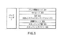
図5は、図1に示されるパックヘッダの内部構造を例示する図である。パックヘッダ1は例えば14バイトで構成されており、ここにはパック開始コード301、”01”コード、システムクロックリファレンスSCR303、多重化レート(例えば8Mbps)304、スタッフィング長305、およびスタッフィングバイト306のフィールドがあり、それぞれのフィールドに該当情報が記述されている。 FIG. 5 is a diagram illustrating the internal structure of the pack header shown in FIG. The
ところで、ストリームオブジェクトSOBの記録中にストリーマに入ってくるアプリケーションパケットAP_PKTは、ストリーマ内部のローカル基準クロックによりタイムスタンプされる。このタイムスタンプで示される時間がアプリケーションパケット到着時間APATである。SOB内の最初のパックに対しては、ストリーマ内部のローカル基準クロック(図5のSCR303または後述する図15のSCRベースに対応)は、そのパック内で開始する最初のアプリケーションパケットのAPATに等しくなる。 By the way, the application packet AP_PKT that enters the streamer during recording of the stream object SOB is time stamped by the local reference clock inside the streamer. The time indicated by this time stamp is the application packet arrival time APAT. For the first pack in the SOB, the local reference clock within the streamer (corresponding to the
図6は、図1に示されるPESヘッダ&サブストリームIDの内部構造を例示する図である。PESヘッダ&サブストリームID6は例えば6バイトで構成されており、ここにはパケット開始コード311、ストリームID312、”11”コード313、PES・CRCフラグ314、PES拡張フラグ316、PESヘッダ長316、サブストリームID317の各記述フィールドが存在する。 FIG. 6 is a diagram illustrating the internal structure of the PES header & substream ID shown in FIG. The PES header &
次に、ロングアプリケーションヘッダ11とショートアプリケーションヘッダ13の詳細について説明する。図7は、図1(c)に示されるロングアプリケーションヘッダ11(または12)の内部構造を例示する図である。また、図8は、図1(i)に示されるアプリケーションヘッダ/ショートアプリケーションヘッダ13(または14)の内部構造を例示する図である。 Next, details of the
図7および図8の図示から分かるように、ロングアプリケーションヘッダ11内のデータ内容の一部がショートアプリケーションヘッダ13のデータ内容になっている。ストリームデータの内容に依存しない共通に必要な情報がショートアプリケーションヘッダ13内に含まれており、全てのストリームデータを情報媒体上に記録するときにストリームデータと一緒にこのショートアプリケーションヘッダ13の内容が記録される。 As can be seen from FIG. 7 and FIG. 8, a part of the data content in the
ところで、デジタルTV放送の映像情報は、一般にMPEG2を用いて情報圧縮されている。したがって、ストリームデータとしてデジタルTV映像情報を情報媒体上に記録した場合、再生時にはMPEG2固有の情報が必要となる。そこで、全てのストリームデータに共通なショートアプリケーションヘッダ13の情報にデジタルTV放送(MPEG2)の再生に必要な情報を付加した情報を、ロングアプリケーションヘッダ11に持たせている。 Incidentally, video information of digital TV broadcasting is generally compressed using MPEG2. Therefore, when digital TV video information is recorded on an information medium as stream data, information specific to MPEG2 is required for reproduction. Therefore, the
以下、図7および図8を参照して、ロングアプリケーションヘッダ11の情報内容およびショートアプリケーションヘッダ13内の情報内容について、具体的に説明する。以下の説明において、特に断りがない限り、同じ参照番号のフィールドは、ロングアプリケーションヘッダ11とショートアプリケーションヘッダ13との間で共通である。 Hereinafter, the information content of the
アプリケーションヘッダ11、13は、その内部にロングアプリケーションヘッダ11の識別フラグを格納する1ビットフィールド326を持つ。この識別フラグが“1”のときはロングアプリケーションヘッダであることが示され、“0”のときはショートアプリケーションヘッダであることが示される。また、アプリケーションヘッダ11、13は、個々のストリームデータに対応したサービスID情報を格納するフィールド330も持つ。このID情報と別の場所に記録してあるサービス情報とのリンクをとることで、各ストリームデータ毎の固有のサービス情報を得ることができる。また、将来アプリケーションヘッダの情報内容を変更できるように、アプリケーションヘッダのバージョン番号がフィールド321に記録されている。 The
さらに、アプリケーションヘッダ11、13内には、モディファイドタイムスタンプのデータ長(バイト数)がフィールド322に記述される。またアプリケーションパケットのデータ長(バイト数)がフィールド323にバイト数で記述される。さらにストリームパケット内に存在するアプリケーションパケットの数がフィールド324に記述される。このアプリケーションパケット数は、ストリームパック内の最初に配置されたモディファイドタイムスタンプが指し示すアプリケーションパケットから数えた数である。さらにストリームパック内の最初に配置されたモディファイドタイムスタンプの先頭位置情報がフィールド325にバイト数で記述される。フィールド326には、ロングアプリケーションヘッダの識別フラグが記述される。 Further, in the
ここで、図8のフィールド327*にはSOB#B・299の開始アプリケーションパケットがストリームパック内に存在することを示すフラグが記述され、図8のフィールド328*にはSOB#B・299の終了アプリケーションパケットがストリームパック内に存在することを示すフラグが記述される。 Here, a flag indicating that the SOB # B • 299 start application packet is present in the stream pack is described in the field 327 * of FIG. 8, and the end of SOB # B • 299 is described in the field 328 * of FIG. A flag indicating that the application packet exists in the stream pack is described.
同様に、図7のフィールド327にはSOB#A・298の開始アプリケーションパケットがストリームパック内に存在することを示すフラグが記述され、図7のフィールド328にはSOB#A・298の終了アプリケーションパケットがストリームパック内に存在することを示すフラグが記述される。 Similarly, a flag indicating that the SOB # A · 298 start application packet exists in the stream pack is described in the field 327 of FIG. 7, and the SOB # A · 298 end application packet is described in the field 328 of FIG. Is described in the stream pack.
アプリケーションヘッダ11、13内のフィールド329には、モディファイドタイムスタンプの基準クロック周波数情報が記述される。 The field 329 in the
さらに、図7に示すロングアプリケーションヘッダ11内のフィールド331には、最大ビットレート情報が記述される。これはデータ溢れ量を制御するモデルのための出力ビットレートパラメータである。また、ロングアプリケーションヘッダ11内のフィールド332には、スムーズバッファサイズが記述される。これはデータ溢れ量を制御するモデル(ストリーマのスムージングバッファモデル)のためのバッファサイズパラメータ(バイト)である。 Furthermore, maximum bit rate information is described in a field 331 in the
図7、図8ではモディファイドタイムスタンプ(図1(b)参照)のデータ長(フィールド322)、モディファイドタイムスタンプの基準クロック周波数(フィールド329)を例示したが、それに限らず、この発明の実施の形態によっては、タイムスタンプの付け直しを行わず、受信直後のタイムスタンプをそのまま情報媒体上に記録することも可能である。その場合には、通常のタイムスタンプのデータ長(フィールド322)および/または通常のタイムスタンプの基準クロック周波数(フィールド329)の情報を用いることができる。 7 and 8 exemplify the data length (field 322) of the modified time stamp (see FIG. 1B) and the reference clock frequency (field 329) of the modified time stamp. However, the present invention is not limited to this. Depending on the form, it is possible to record the time stamp immediately after reception on the information medium as it is without re-attaching the time stamp. In that case, information on the data length of the normal time stamp (field 322) and / or the reference clock frequency (field 329) of the normal time stamp can be used.
上記スムージングバッファモデルとは、SOB内に記録されるアプリケーションデータの平均ビットレートおよび瞬間的な途切れを制限するために定義されたものである。パケットヘッダ、PESヘッダ、アプリケーションヘッダ、アプリケーションタイムスタンプ、およびスタッフィングを含む完全なパックデータは、このモデルのスムージングバッファに入る。このスムージングバッファからアプリケーションパケットを取り除くに際しては、該当アプリケーションパケットの先頭バイトと先行アプリケーションパケットの最終バイトとの間に格納された全てのデータバイトが、スムージングバッファから瞬間的に削除される。 The smoothing buffer model is defined to limit the average bit rate and instantaneous interruption of application data recorded in the SOB. The complete packed data including packet header, PES header, application header, application time stamp, and stuffing goes into the smoothing buffer of this model. When removing an application packet from the smoothing buffer, all data bytes stored between the first byte of the application packet and the last byte of the preceding application packet are instantaneously deleted from the smoothing buffer.
MPEG2プログラムストリームをスムージングバッファに導入でき、かつアプリケーションタイムスタンプにより規定され正しく再構成された再生タイミングに基づいてその全てのアプリケーションパケットをスムージングバッファから取り除くことができるようにSOBが媒体(DVD−RAMディスクなど)に記録されるなら、それはストリーマのスムージングバッファモデルにより与えられた制限に従うものと解釈される。この制限は、スムージングバッファのサイズおよびMPEG2プログラムストリームの最大プログラム多重化レート(図5の304あるいは図15(e)のプログラム多重化レート)の最大値(10.08Mbps)に応じて定めることができる。 The SOB is a medium (DVD-RAM disc) so that the MPEG2 program stream can be introduced into the smoothing buffer and all its application packets can be removed from the smoothing buffer based on the playback timing correctly defined by the application time stamp. Etc.) is interpreted as subject to the restrictions given by the streamer's smoothing buffer model. This limitation can be determined according to the size of the smoothing buffer and the maximum value (10.08 Mbps) of the maximum program multiplexing rate of the MPEG2 program stream (304 in FIG. 5 or the program multiplexing rate in FIG. 15 (e)). .
記録(録画)中に、パックを形成するに十分なアプリケーションデータがスムージングバッファ内に貯まれば、直ちに、パックをスムージングバッファからトラックバッファに転送できる。そのための条件は、(1)パックがアプリケーションパケットにより完全に埋められるか、(2)システムクロックリファレンスSCRとローカルクロック(27MHz)とのずれが所定のしきい値(秒数で表される時間値)を越えるかしたときに、満足される。 If sufficient application data is stored in the smoothing buffer during recording (recording), the pack can be immediately transferred from the smoothing buffer to the track buffer. Conditions for this are: (1) the pack is completely filled with application packets, or (2) a time value in which the difference between the system clock reference SCR and the local clock (27 MHz) is represented by a predetermined threshold value (seconds). ) Is satisfied.
いま、先行パックのSCRをSCR_prevとしてみる。この場合、アプリケーションパケットの開始が含まれない後続パックに対しては、”SCR=SCR_prev+2048×8ビット/10.08MHz”の関係から、それらパックのSCRを求めることができる。 Now, consider the SCR of the preceding pack as SCR_prev. In this case, for subsequent packs that do not include the start of the application packet, the SCRs of those packs can be obtained from the relationship of “SCR = SCR_prev + 2048 × 8 bits / 10.08 MHz”.
一方、アプリケーションパケットの開始を少なくとも1つ含む後続パックに対しては、”SCR=(SCR_prev+2048×8ビット/10.08MHz;あるいはAPAT[40…0])の最大値”から、それらパックのSCRを求めることができる。ここで、APATとは、該当パック内で開始する先頭アプリケーションパケットの到着時間を指す。 On the other hand, for subsequent packs including at least one start of application packet, the SCR of those packs is determined from “SCR = (SCR_prev + 2048 × 8 bits / 10.08 MHz; or APAT [40... 0]) maximum value”. Can be sought. Here, APAT refers to the arrival time of the first application packet that starts in the corresponding pack.
SOB内の最初のパックに対して、そのSCRはそのパック内で開始する先頭アプリケーションパケットのAPATと同じになる。このことを具体的に例示すれば、”SCR[40…0]=APAT[40…0]”となる。このSCR[40…0]の次のSCR[41]はゼロとなる。なお、SCR[40…0]の[40…0]はこのSCRを構成する情報ビット(40)〜(0)の内容を示し、APAT[40…0]の[40…0]はこのAPATを構成する情報ビット(40)〜(0)の内容を示す。同様に、SCR[41]の[41]はこのSCRを構成する情報ビット(41)の内容を示す。 For the first pack in the SOB, its SCR will be the same as the APAT of the first application packet starting in that pack. To illustrate this specifically, “SCR [40... 0] = APAT [40... 0]”. The SCR [41] next to the SCR [40... 0] becomes zero. [40 ... 0] of SCR [40 ... 0] indicates the contents of information bits (40) to (0) constituting this SCR, and [40 ... 0] of APAT [40 ... 0] indicates this APAT. The contents of information bits (40) to (0) to be configured are shown. Similarly, [41] of SCR [41] indicates the contents of information bit (41) constituting this SCR.
ファームウエアのプログラミングで例示すれば、上述したことは、以下のように表現できる:
if (APAT[40...0] > (SCR_prev + 2048*8bits/10.08Mbps)), then
SCR[40...0] = APAT[40...0]
SCR[41] = 0
else
SCR[40...0] = (SCR_prev + 2048*8bits/10.08Mbps)[40...0]
SCR[41] = 0
endif
なお、再生中にスムージングバッファが満杯になれば、アプリケーションパケットを出力する処理を直ちに開始することができる。To illustrate by firmware programming, the above can be expressed as:
if (APAT [40 ... 0]> (SCR_prev + 2048 * 8bits / 10.08Mbps)), then
SCR [40 ... 0] = APAT [40 ... 0]
SCR [41] = 0
else
SCR [40 ... 0] = (SCR_prev + 2048 * 8bits / 10.08Mbps) [40 ... 0]
SCR [41] = 0
endif
If the smoothing buffer becomes full during reproduction, the process of outputting the application packet can be started immediately.
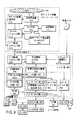
図9は、この発明の一実施の形態に係るストリームデータ記録再生システム(光ディスク装置/ストリーマ、STB装置)の構成を説明する図である。この実施の形態では、情報媒体201として、DVD−RAMディスクのような記録/再生可能光ディスクを想定している。 FIG. 9 is a diagram for explaining the configuration of a stream data recording / reproducing system (optical disc apparatus / streamer, STB apparatus) according to an embodiment of the present invention. In this embodiment, it is assumed that the
このストリームデータ記録再生装置は、光ディスク装置(ストリーマ)415、STB装置416およびその周辺機器から構成される。周辺機器としては、ビデオミキシング部405、フレームメモリ部406、外部スピーカ433、パーソナルコンピュータ(PC)435、モニタTV437、D/Aコンバータ432、436、I/F部431、434等がある。 This stream data recording / reproducing apparatus includes an optical disk device (streamer) 415, an STB device 416, and peripheral devices. Peripheral devices include a video mixing unit 405, a frame memory unit 406, an
光ディスク装置415は、ディスクドライブを含む記録再生部409と、記録再生部409へのストリームデータ(あるいは記録再生部409からのストリームデータ)を処理するデータプロセサ部(以下D−PRO部と略記する)410と、D−PRO部410からオーバーフローしてきたストリームデータを一時記憶する一時記憶部(前述したスムージングバッファとして利用可能)411と、記録再生部409およびD−PRO部410の動作を制御する光ディスク装置制御部412とを備えている。 The optical disk device 415 includes a recording / playback unit 409 including a disk drive, and a data processor unit (hereinafter abbreviated as a D-PRO unit) that processes stream data to the recording / playback unit 409 (or stream data from the recording / playback unit 409). 410, a temporary storage unit 411 (which can be used as the above-described smoothing buffer) that temporarily stores stream data overflowed from the D-
光ディスク装置415はさらに、STB装置416からIEEE1394等を介して送られてきたストリームデータを受ける(あるいはIEEE1394等を介してSTB装置416へストリームデータを送る)データ転送インターフェイス部414と、データ転送インターフェイス部414で受けたストリームデータを情報媒体(RAMディスク)201に記録する信号形式に変換する(あるいは媒体201から再生されたストリームデータをIEEE1394等の信号形式に変換する)フォーマッタ/デフォーマッタ部413とを備えている。 The optical disk device 415 further receives a stream data sent from the STB device 416 via the IEEE 1394 or the like (or sends the stream data to the STB device 416 via the IEEE 1394 or the like), and a data transfer interface unit. A formatter /
具体的には、データ転送インターフェイス部414のIEEE1394受信側は、基準クロック発生部(ローカルクロック)440のタイムカウント値に基づいて、ストリームデータ転送開始からの時間を読み込む。このタイムカウント値(時間情報)に基づいて、ストリームデータをストリームブロック毎(あるいはSOBU毎)に切り分ける区切れ情報を作成するとともに、この区切れ情報に対応したセルの切り分け情報およびプログラムの切り分け情報、さらにはPGCの切り分け情報を作成する。 Specifically, the IEEE 1394 receiver side of the data
フォーマッタ/デフォーマッタ部413は、STB装置416から送られてきたストリームデータをストリームパックの列に変換し、変換されたストリームパック列をD−PRO部410へ入力する。入力されたストリームパックはセクタと同じ2048バイトの一定サイズを持っている。D−PRO部410は、入力されたストリームパックを16セクタ毎にまとめてECCブロックにして、記録再生部409へ送る。 The formatter /
記録再生部409において媒体201への記録準備ができていない場合には、D−PRO部410は、記録データを一時記憶部411に転送して一時保存し、記録再生部409においてデータ記録準備ができるまで待つ。記録再生部409において記録準備ができた段階で、D−PRO部410は一時記憶部411に保存されたデータを記録再生部409に転送する。これにより、媒体201への記録が開始される。一時記憶部411に保存されたデータの記録が済むと、その続きのデータはフォーマッタ/デフォーマッタ部413からD−PRO部410へシームレスに転送されるようになっている。ここで、一時記憶部411は、高速アクセス可能で数分以上の記録データを保持できるようにするため、大容量メモリを想定している。 If the recording / playback unit 409 is not ready for recording on the medium 201, the D-
なお、フォーマッタ/デフォーマッタ部413を介して記録ビットストリームに付されるタイムスタンプ情報は、基準クロック発生部440から得ることができる。また、フォーマッタ/デフォーマッタ部413を介して再生ビットストリームから取り出されたタイムスタンプ情報(SCR)は、基準クロック発生部440にセットすることができる。 The time stamp information attached to the recording bitstream via the formatter /
情報媒体201に記録されたストリームデータ内のパックヘッダには、基準クロック(システムクロックリファレンスSCR)が記録されている。この媒体201に記録されたストリームデータ(SOBまたはSOBU)を再生する場合において、基準クロック発生部440は、媒体201から再生された基準クロック(SCR)に適合される(SCRの値が基準クロック発生部440にセットされる)。つまり、SOBあるいはSOBUのデータを再生するために、ストリーマ(光ディスク装置415)内の基準クロック(基準クロック発生部440)を、再生が開始される最初のストリームパック内に記述されたシステムクロックリファレンスSCRに合わせる。その後は、基準クロック発生部440のカウントアップは自動的に行われる。 A reference clock (system clock reference SCR) is recorded in the pack header in the stream data recorded on the
STB部416は、衛星アンテナ421で受信したデジタル放送電波の内容を復調し、1以上の番組が多重化された復調データ(ストリームデータ)を提供するデモジュレータ422と、デモジュレータ422で復調されたデータから(ユーザが希望する)特定番組の情報を選択する受信情報セレクタ部423とを備えている。受信情報セレクタ部423で選択された特定番組の情報(トランスポートパケット)を情報媒体201に記録する場合は、STB制御部404の指示に従い、セレクタ部423は特定番組のトランスポートパケットだけを含むストリームデータを、データ転送インターフェイス部420を介して、IEEE1394転送により、光ディスク装置415のデータ転送インターフェイス部414に送る。受信情報セレクタ部423で選択された特定番組の情報(トランスポートパケット)を記録することなく単に視聴するだけの場合は、STB制御部404の指示に従い、セレクタ部423は特定番組のトランスポートパケットだけを含むストリームデータを、デコーダ部402の多重化情報分離部425に送る。 The STB unit 416 demodulates the contents of the digital broadcast radio wave received by the
一方、情報媒体201に記録された番組を再生する場合は、IEEE1394のシリアルバスを介して光ディスク装置415からSTB装置416に送られてきたストリームデータは、セレクタ部423を介してデコーダ部402の多重化情報分離部425に送られる。多重化情報分離部425は、セレクタ部423から送られてきたストリームデータに含まれる各種パケット(ビデオパケット、オーディオパケット、サブピクチャパケット等)を、内部メモリ部426上で、各パケットのIDにより区分けする。そして、区分けされたパケットを、それぞれ該当するデコード部(ビデオデコード部428、サブピクチャデコード部429、オーディオデコード部430に分配する。 On the other hand, when the program recorded on the
ビデオデコード部428は、多重化情報分離部425から送られてきた(MPEGエンコードされた)ビデオパケットをデコードして、動画データを生成する。その際、MPEGビデオデータ中のIピクチャから記録内容を代表する縮小画像(サムネールピクチャ)を生成する機能を持たせるために、ビデオデコード部428は、代表画像(サムネール)生成部439を内蔵している。ビデオデコード部428でデコードされた動画(および/または生成部439で生成された代表画像)と、サブピクチャデコード部429でデコードされたサブピクチャ(字幕、メニュー等の情報)と、オーディオデコード部430でデコードされた音声とは、ビデオプロセサ部438を介してビデオミキシング部405へ送出される。 The
ビデオミキシング部405は、フレームメモリ部406を利用して、動画に字幕等を重ねたデジタル映像を作り出す。このデジタル映像は、D/A変換器436を介してアナログ映像化され、モニタTV437に送られる。また、ビデオミキシング部405からのデジタル映像は、I/F部434およびIEEE194等の信号ラインを介して、パーソナルコンピュータ435に適宜取り込まれる。一方、オーディオデコード部430でデコードされたデジタルオーディオ情報は、D/A変換器432および図示しないオーディオアンプを介して、外部スピーカ433に送られる。また、デコードされたオーディオ情報は、I/F部431を介して外部にデジタル出力される。なお、STB装置416内の動作タイミングは、システムタイムカウンタ(STC)部424からのクロックにより決定される。 The video mixing unit 405 uses the frame memory unit 406 to create a digital image in which captions are superimposed on a moving image. This digital video is converted into an analog video via the D /
上述したSTB制御部404による指示(STB装置416の内部構成各々の動作制御)等は、プログラムメモリ部404aに格納された制御プログラムにより実行される。その際、STB制御部404による制御過程においてワークメモリ部(RAM)407が適宜利用される。 The above-described instruction by the STB control unit 404 (operation control of each internal configuration of the STB device 416) and the like are executed by a control program stored in the program memory unit 404a. At that time, the work memory unit (RAM) 407 is appropriately used in the control process by the STB control unit 404.
図9に示すストリームデータ記録再生装置では光ディスク装置415とSTB装置416との間でデータ転送インターフェイス部414、420を介してストリームデータの転送処理が行われる。MPEG2の形式で圧縮されたデジタルTVの映像情報が間欠なく連続して転送されるために必要な情報として、データ転送インターフェイス部414と420間で情報転送するときの最大ビットレート(情報の最大転送速度)の情報がロングアプリケーションヘッダ11のフィールド327(図7)に記録されている。また、光ディスク装置415およびSTB装置416のデータ転送インターフェイス部414、420間でMPEG2映像情報のリアルタイム連続転送を保証するために必要な情報、すなわちデータ転送インターフェイス部414、420内部で持つ必要のあるメモリサイズが、スムーズバッファサイズとして、図7のフィールド332に記録されている。 In the stream data recording / reproducing apparatus shown in FIG. 9, stream data transfer processing is performed between the optical disk device 415 and the STB device 416 via the data
このSTB制御部404およびデコーダ部402を含めSTB装置416の内部動作のタイミングは、STC部424からのクロックで規制できる。また、光ディスク装置415の基準クロック発生部440とSTB装置416のSTC部424を同期させることで、光ディスク装置415およびSTB装置416を含めたストリーマシステム全体の動作タイミングを規制できる。 The timing of internal operations of the STB device 416 including the STB control unit 404 and the decoder unit 402 can be regulated by a clock from the
基準クロック発生部440とSTC部424を同期させる方法としては、データ転送インターフェイス部414とデータ転送インターフェイス部420との間で受け渡されるストリームデータ中の基準クロック(SCR)により、基準クロック発生部440およびSTC部424をセットする方法がある。 As a method of synchronizing the reference clock generation unit 440 and the
具体的には、STB装置416から光ディスク装置(ストリーマ)415に送られてくるストリームデータに含まれるSOB内の最初のパックに対して、ストリーマ415内部のローカル基準クロック(440)を、そのパック内で開始する最初のアプリケーションパケットのAPATに設定することになる。 Specifically, for the first pack in the SOB included in the stream data sent from the STB device 416 to the optical disk device (streamer) 415, the local reference clock (440) inside the streamer 415 is stored in the pack. Will be set to APAT of the first application packet starting with.
図19の装置構成を機能別にみると、STB装置416内は、「受信時刻管理部」と、「ストリームデータ内容解析部」と、「ストリームデータ転送部」と、「時間関連情報生成部」とに分割/分類できる。 Looking at the device configuration of FIG. 19 by function, the STB device 416 includes a “reception time management unit”, a “stream data content analysis unit”, a “stream data transfer unit”, and a “time related information generation unit”. Can be divided / classified.
ここで、「受信時刻管理部」は、デモジュレータ(復調部)422、受信情報セレクタ部423、多重化情報分離部425、STB制御部404等で構成される。この「受信時刻管理部」は、衛星アンテナ421でデジタルTV放送を受信し、受信した放送情報内の各トランスポートパケット毎の受信時刻を記録する。 Here, the “reception time management unit” includes a demodulator (demodulation unit) 422, a reception
「ストリームデータ内容解析部」は、多重化情報分離部425、STB制御部404等で構成される。この「ストリームデータ内容解析部」は、受信したストリームデータの中身を解析し、I,B,Pの各ピクチャ位置および/またはPTS(プレゼンテーションタイムスタンプ)値を抽出する。 The “stream data content analysis unit” includes a multiplexed information separation unit 425, an STB control unit 404, and the like. This “stream data content analysis unit” analyzes the contents of the received stream data and extracts the I, B, and P picture positions and / or PTS (presentation time stamp) values.
「ストリームデータ転送部」は、多重化情報分離部425、受信情報セレクタ部423、STB制御部404、データ転送インターフェイス部420等で構成される。この「ストリームデータ転送部」は、各トランスポートパケット毎の差分受信時刻間隔を保持したままストリームデータを光ディスク装置415へ転送する。 The “stream data transfer unit” includes a multiplexed information separation unit 425, a reception
「時間関連情報生成部」は、多重化情報分離部425、STB制御部404、データ転送インターフェイス部420等で構成される。この「時間関連情報生成部」は、「受信時刻管理部」で記録した受信時刻(タイムスタンプ)情報と「ストリームデータ内容解析部」で抽出した表示時刻情報(PTS値および/またはフィールド数)との間の関係情報を作成する。 The “time related information generation unit” includes a multiplexed information separation unit 425, an STB control unit 404, a data transfer interface unit 420, and the like. The “time-related information generation unit” includes reception time (time stamp) information recorded by the “reception time management unit”, display time information (PTS value and / or number of fields) extracted by the “stream data content analysis unit”, and Create relationship information between.
この発明の一実施の形態では、STB装置416で取り込まれたアプリケーションパケット(トランスポートパケット)間の時間間隔を保持したままディスク201に記録可能とし、受信時の各パケット間の時間間隔を保持したまま再生(STB装置へ光ディスク装置から送信)可能としている。ただし、この場合、STB装置416内の基準クロック周波数(STC424)と、光ディスク装置415内の基準クロック周波数(ローカルクロック440)とが異なるために、光ディスク装置415で記録する前にタイムスタンプの付け直しを行い、光ディスク装置415内のクロックをパックヘッダに記録するようにしている。これにより、再生時には、受信時の各パケット間の時間間隔を保持したまま光ディスク装置415からSTB装置416へアプリケーションパケットを送信することが可能となる。その結果、STB装置416では、データ転送インターフェイス部420および受信情報セレクタ部423を通して多重化情報分離部425に取り込まれたアプリケーションパケットは、衛星アンテナ421を通じて取り込まれたときと同様な処理でデコード可能となる。 In one embodiment of the present invention, the time interval between application packets (transport packets) captured by the STB device 416 can be recorded on the
すなわち、先に説明した「受信時刻管理部」が機能し、アプリケーションパケットの受信時刻(取り込み時刻)およびアプリケーションパケットが多重情報分離部425のメモリ部426に取り込まれる。次に「ストリームデータ内容解析部」ではメモリ部426に記憶されているアプリケーションパケット内の情報を解析し、そのヘッダであるトランスポートパケットヘッダ、ペイロードを認識する(図14参照)。ペイロードの種類としては、ピクチャ情報、オーディオ情報、副映像情報、さらにはデータ、テキスト情報なども含まれる。それぞれの情報には、PTS(プレゼンテーションタイムスタンプまたは再生タイムスタンプ)が付加されている。トランスポートパケットヘッダには、追随するペイロードがどのようなデータであるかの識別情報や各種の属性情報が含まれているので、この情報にしたがって、ピクチャ情報、オーディオ情報、副映像情報などの切り出し、それぞれの情報に対応するPTSの抽出が行われる。 That is, the “reception time management unit” described above functions, and the application packet reception time (capture time) and the application packet are captured in the memory unit 426 of the multiplex information demultiplexing unit 425. Next, the “stream data content analysis unit” analyzes the information in the application packet stored in the memory unit 426, and recognizes the transport packet header and payload which are the headers (see FIG. 14). The type of payload includes picture information, audio information, sub-picture information, data, text information, and the like. Each information is added with a PTS (presentation time stamp or playback time stamp). Since the transport packet header includes identification information on the type of payload to be followed and various attribute information, picture information, audio information, sub-picture information, etc. are extracted according to this information. The PTS corresponding to each information is extracted.
各情報は、それぞれ対応するビデオデコード部428、オーディオデコード部430、サブピクチャデコード部429に入力されデコードされる。ビデオデコード部428からのビデオ信号と、サブピクチャデコード部429からの副映像信号とは、ビデオプロセッサ部438に入力される。ビデオプロセッサ部438では、デコードされたビデオ信号と副映像信号との合成処理、その他ビデオ信号に必要な処理が行なわれる。ビデオプロセッサ部438からの出力ビデオ信号は、ビデオミキシング部405を介してデジタルアナログ変換部436に入力され、ここでアナログ信号となり、テレビジョン受像機437でモニタされる。 Each piece of information is input to the corresponding
ビデオミキシング部405には、フレームメモリ部406が接続されており、ミキシング処理のときの一時保管部として利用される。またミキシング部405のデジタル出力(映像、副映像、オーディオを含む)は、インターフェイス434を介してパーソナルコンピュータ435に与えることもできる。オーディオデコード部430の出力は、インターフェイス部431を介してデジタル出力として取り出すことができる。またオーディオデータは、デジタルアナログ変換部432を介してアナログ信号に変換されスピーカ433に入力される。 A frame memory unit 406 is connected to the video mixing unit 405, and is used as a temporary storage unit at the time of mixing processing. The digital output (including video, sub-video, and audio) of the mixing unit 405 can also be given to the
上述したように、図9の装置では、受信時の各パケット間の時間間隔を保持したまま再生(光ディスク装置からSTB装置への送信)可能としている。このことは、しかしながら、記録媒体201に対する物理的記録箇所が間欠的にならないことを意味するものではない。場合によっては、物理的な記録箇所が間隔を有することもあるが、基本的には連続的に記録される。しかし、上述したようにパケット間には時間間隔が時間情報上で存在するので、記録媒体からのデータ再生量がSTB装置の単位時間当たりのデータ処理量よりも多くなることがある。この場合には、光ディスク装置のキックバック機能が働くようになっており、取り込んだ再生データの一部を破棄し、再度、記憶媒体201から読み取るようになっている。これにより、アプリケーションパケットは、アンテナより受信したときと同様なタイミングでSTB装置へ伝送される。 As described above, in the apparatus of FIG. 9, reproduction (transmission from the optical disk apparatus to the STB apparatus) is possible while maintaining the time interval between the packets at the time of reception. However, this does not mean that the physical recording location on the
図10は、この発明の一実施の形態に係るストリームデータ記録手順を説明するフローチャート図である。まず、図9のSTB装置416においてデジタルTV放送の映像情報が受信される(ステップS1)。一般にデジタルTV放送での受信情報は、1個のトランスポンダ内に複数番組情報が時分割多重化されている。その情報に対して、受信情報セレクタ部423内で、特定番組のみのアプリケーションパケットが抽出される。 FIG. 10 is a flowchart for explaining a stream data recording procedure according to one embodiment of the present invention. First, digital TV broadcast video information is received by the STB device 416 of FIG. 9 (step S1). In general, received information in digital TV broadcasting is time-division multiplexed with a plurality of program information in one transponder. For the information, an application packet of only a specific program is extracted in the reception
図9の説明で述べた「受信時刻管理部」では、必要な番組情報が多重化情報分離部425内のメモリ部426内に一時保管される。これと同時に、「受信時刻管理部」では各アプリケーションパケット毎の受信時刻が計測され、その計測値が、図1(a)に示したようなオリジナルタイムスタンプとして各アプリケーションパケット毎に付加される(ステップS2)。ここで、オリジナルタイムスタンプは、IEEE1394の規格に基いてデータ伝送するとき(各アプリケーションパケットを伝送するとき)のタイムスタンプである。このように付加されたオリジナルタイムスタンプ情報は、メモリ部426内に記録される。 In the “reception time management unit” described with reference to FIG. 9, necessary program information is temporarily stored in the memory unit 426 in the multiplexed information separation unit 425. At the same time, the “reception time management unit” measures the reception time for each application packet, and the measured value is added to each application packet as an original time stamp as shown in FIG. Step S2). Here, the original time stamp is a time stamp when data is transmitted (when each application packet is transmitted) based on the IEEE 1394 standard. The original time stamp information added in this way is recorded in the memory unit 426.
次に、図9の説明で述べた「ストリームデータ内容解析部」では、メモリ部426内に記録されたアプリケーションパケット内の情報が解析される。具体的には、アプリケーションパケット列から各ピクチャ境界位置を切り出す処理と、PTS(プレゼンテーションタイムスタンプ)情報の抽出処理とが行なわれる。また、「ストリームデータ内容解析部」では、ストリームデータ内容からデジタルTV放送の映像情報であるか否かの判定も行なわれる。以上の処理が行なわれたあと、オリジナルタイムスタンプのタイミングに合わせてストリームデータがデータ転送インターフェイス部420に転送される。 Next, in the “stream data content analysis unit” described in the description of FIG. 9, information in the application packet recorded in the memory unit 426 is analyzed. Specifically, processing for extracting each picture boundary position from the application packet sequence and processing for extracting PTS (presentation time stamp) information are performed. In the “stream data content analysis unit”, it is also determined whether or not the video data is digital TV broadcast video information from the stream data content. After the above processing is performed, the stream data is transferred to the data transfer interface unit 420 in accordance with the timing of the original time stamp.
データ転送インターフェイス部414とデータ転送インターフェイス部420との間でストリームデータを転送するとき、このデータ転送と同時に、データ転送インターフェイス部414内部で発生させたデジタルTV映像情報識別フラグが添付されて転送される(ステップS3)。 When stream data is transferred between the data
光ディスク装置415側では、データ転送インターフェイス部414から出力された各アプリケーションパケットに対して、装置内部の基準クロック発生部440で生成する基準クロックに合わせて、タイムスタンプの付け替え(モディファイドタイムスタンプの付け直し)が行なわれる(ステップS4)。 On the optical disk device 415 side, time stamp replacement (modified time stamp reattachment) is performed on each application packet output from the data
このタイムスタンプの付け替えにより、STB装置416から光ディスク装置(ストリーマ)415に送られてくるストリームデータに含まれるストリームオブジェクトSOB内の最初のパックに対して、ストリーマ415内部のローカル基準クロック(440)を、そのパック内で開始する最初のアプリケーションパケットのAPATに設定することになる。換言すれば、SOBの記録中にストリーマに入ってくるアプリケーションパケットAP_PKTは、ストリーマ内部のローカル基準クロックによりタイムスタンプされ(このタイムスタンプで示される時間がアプリケーションパケット到着時間APAT)、SOB内の最初のパックに対しては、ストリーマ内部のローカル基準クロック(図5のSCR303または後述する図15のSCRベースに対応)は、そのパック内で開始する最初のアプリケーションパケットのAPATに等しくなる。 By changing the time stamp, the local reference clock (440) inside the streamer 415 is applied to the first pack in the stream object SOB included in the stream data sent from the STB device 416 to the optical disk device (streamer) 415. , The APAT of the first application packet starting in the pack will be set. In other words, the application packet AP_PKT that enters the streamer during SOB recording is time stamped by the local reference clock inside the streamer (the time indicated by this time stamp is the application packet arrival time APAT), and the first in the SOB. For a pack, the local reference clock inside the streamer (corresponding to the
上記ステップS4のタイムスタンプ付け替え処理と並行して、光ディスク装置制御部415ではデジタルTV映像情報識別フラグが認識され、図1(c)または図7で示されたロングアプリケーションヘッダ11の設定が行なわれる(ステップS5)。 In parallel with the time stamp replacement process in step S4, the optical disc apparatus control unit 415 recognizes the digital TV video information identification flag and sets the
ストリームデータを情報媒体201上に記録する処理においては、図9のD−PRO(デジタルプロセッサ)部410がデータ制御を行い、記録再生部409が動作する(ステップS6〜ステップS9)。このときは、図1(c)に示すように、各セクタ毎に、順次パックヘッダ1、PESヘッダ&サブストリームID6、ロングアプリケーションヘッダ11が記録され、データエリア21内では順次モディファイドタイムスタンプおよびアプリケーションパケットが記録されて行く。 In the process of recording the stream data on the
ここで、パックヘッダ1には図5に示すSCR303(後述する図15のSCRベースに対応)が記録されている。情報媒体201にストリームデータを記録するときの時刻情報として基準クロック発生部440から出力されたクロックのカウント値が、このSCR情報として記録される。 Here, the
ステップS6〜ステップS9の中身をより具体的に説明すると、まずD−PRO部410を介して記録再生部409でストリームパック(セクタ)毎にパックヘッダが情報媒体に記録される(ステップS6)。次に、D−PRO部410を介して記録再生部409でストリームパック(セクタ)毎にPESヘッダ&サブストリームIDが情報媒体に記録される(ステップS7)。続いて、D−PRO部410を介して記録再生部409でストリームパック(セクタ)毎にロングアプリケーションヘッダが情報媒体に記録される(ステップS8)。そして、D−PRO部410を介して記録再生部409でストリームパック(セクタ)毎にモディファイドタイムスタンプおよびアプリケーションパケットが情報媒体に記録される(ステップS7)。 The contents of step S6 to step S9 will be described more specifically. First, a pack header is recorded on the information medium for each stream pack (sector) by the recording / reproducing unit 409 via the D-PRO unit 410 (step S6). Next, the PES header & substream ID is recorded on the information medium for each stream pack (sector) by the recording / reproducing unit 409 via the D-PRO unit 410 (step S7). Subsequently, a long application header is recorded on the information medium for each stream pack (sector) by the recording / reproducing unit 409 via the D-PRO unit 410 (step S8). Then, the modified playback time stamp and the application packet are recorded on the information medium for each stream pack (sector) by the recording / playback unit 409 via the D-PRO unit 410 (step S7).
以上の処理により、図9の光ディスク装置(またはストリーマ)415内では、基準クロック発生部440からの基準クロックを用いて作成した時間情報(モディファイドタイムスタンプ/SCR)を、データの送出/転送のタイミングを得るための情報として利用できるようになる。 Through the above processing, in the optical disc apparatus (or streamer) 415 of FIG. 9, the time information (modified time stamp / SCR) created by using the reference clock from the reference clock generation unit 440 is used as the data transmission / transfer timing. It can be used as information for obtaining.
以上の処理を別の言葉で表現すると、以下のようになる。すなわち、情報媒体上にストリームデータを記録する場合において、前記ストリームデータを記録する第1の記録単位(ストリームパック/セクタ)および第2の記録単位(アプリケーションパケット)が用意される。そして、前記第1の記録単位(ストリームパック/セクタ)毎に第1のヘッダ(パックヘッダ)情報が記録され、前記第2の記録単位(アプリケーションパケット)毎に時間情報(タイムスタンプ)が記録され、前記第2の記録単位(アプリケーションパケット)毎に前記ストリームデータが記録される。また、前記第1のヘッダ(パックヘッダ)情報内に所定のシステムクロック情報が記録されるとともに、前記第2の記録単位(アプリケーションパケット)毎に記録される前記時間情報(タイムスタンプ)が、前記所定のシステムクロックの値に連動して設定される(ステップS4)。 The above processing is expressed in different words as follows. That is, when recording stream data on an information medium, a first recording unit (stream pack / sector) and a second recording unit (application packet) for recording the stream data are prepared. Then, first header (pack header) information is recorded for each first recording unit (stream pack / sector), and time information (time stamp) is recorded for each second recording unit (application packet). The stream data is recorded for each second recording unit (application packet). In addition, predetermined system clock information is recorded in the first header (pack header) information, and the time information (time stamp) recorded for each second recording unit (application packet) is It is set in conjunction with a predetermined system clock value (step S4).
図11は、この発明の一実施の形態に係るストリームデータ再生手順を説明するフローチャート図である。この再生手順において、まずパックヘッダ1から再生が開始される(ステップS31)。 FIG. 11 is a flowchart for explaining the stream data reproduction procedure according to the embodiment of the present invention. In this reproduction procedure, reproduction is first started from the pack header 1 (step S31).
パックヘッダ1にはストリームデータを記録するときの時刻情報として基準クロック発生部440から出力されたクロックのカウント値が記録されており、その値に合わせて基準クロック発生部440の初期値の再設定が行なわれる(ステップS32)。 The
その直後に、図9の情報再生部409で、情報媒体201上に記録されたタイムスタンプおよびアプリケーションパケットが再生され、その再生データが一時記憶部411に一時保管される(ステップS33)。 Immediately thereafter, the information reproduction unit 409 in FIG. 9 reproduces the time stamp and application packet recorded on the
情報媒体201に記録されたモディファイドタイムスタンプは、前述したSCR303に連動して設定されている。このことから、基準クロック発生部440から発生した基準クロックのカウント値がモディファイドタイムスタンプの値に一致したときに、一時記憶部411内に一時記録されたモディファイドタイムスタンプとそれに関連したアプリケーションパケットがデータ転送インターフェイス部414に転送される(ステップS34)。 The modified time stamp recorded on the
データ転送インターフェイス部414内部では、その内部に持っている基準クロックに合わせてタイムスタンプ値が付け直されて、一時記憶部411から転送されてきた情報がデータ転送インターフェイス部420に転送される。 In the data
ところで、情報媒体201上に点在記録されたストリームデータを記録再生部409内の光学ヘッド(図示せず)がアクセスして再生する場合、モディファイドタイムスタンプの連続性が崩れる。そこで、情報媒体201上に点在記録されたストリームデータに光学ヘッドがアクセスし(ステップS35)、情報媒体上の大きく離れた位置で再生開始する場合には、次のような処理が行われる。すなわち、図9の記録再生部409で情報媒体201上に記録されたパックヘッダからSCR303が再生され(ステップS36)、再生されたSCRの値に合わせて基準クロック発生部440の値が再設定される(ステップS37)。 By the way, when stream data recorded on the
このような処理により、基準クロック発生部440から得られるSCRの値が、再生されるパケットのタイムスタンプに同期可能な関係になる。この同期関係が確立されてから、情報再生部409において、情報媒体上に記録されたタイムスタンプおよびアプリケーションパケットが再生される(ステップS38)。最後に、基準クロック発生部440から発生した基準クロックのカウント値がモディファイドタイムスタンプの値に一致したときに、一時記憶部411内に一時記録されたモディファイドタイムスタンプとそれに関連したアプリケーションパケットがデータ転送インターフェイス部414に転送される(ステップS39)。 By such processing, the SCR value obtained from the reference clock generation unit 440 is synchronized with the time stamp of the packet to be reproduced. After this synchronization relationship is established, the information reproducing unit 409 reproduces the time stamp and application packet recorded on the information medium (step S38). Finally, when the count value of the reference clock generated from the reference clock generation unit 440 matches the value of the modified time stamp, the modified time stamp temporarily recorded in the temporary storage unit 411 and the associated application packet are transferred. The data is transferred to the interface unit 414 (step S39).
データ転送インターフェイス部414に転送された再生情報はIEEE1394ライン等を介してSTB装置416に送られ、そこで必要なデコードが行われる。デコードされた情報(媒体201上の記録コンテンツ)は、図9のTV437、スピーカ433等により再生される。 The reproduction information transferred to the data
以上の処理を別の言葉で表現すると、以下のようになる。すなわち、記録されたビットストリームに対する再生データを表すストリームオブジェクト(SOB)が1以上集まってストリームデータが構成され、前記ストリームオブジェクト(SOB)が1以上のストリームパック(S_PCK)で構成され、前記ストリームパック(S_PCK)はパックヘッダとストリームパケット(S_PKT)とで構成され、前記パックヘッダが所定の時間情報(SCR)を含み、前記ストリームパケット(S_PKT)が所定のタイムスタンプ(ATS)が付されたアプリケーションパケット(AP_PKT)を1以上含み、(ストリーマに)入ってくる前記アプリケーションパケット(AP_PKT)が前記所定の時間情報(SCR)に対応した(ストリーマ内部の)ローカル基準クロック(図9の440)によりタイムスタンプされ、前記タイムスタンプの情報が前記ストリームパック(S_PCK)内に記録された形式で前記ストリームオブジェクト(SOB)が記録された情報媒体(201)から記録情報を再生する場合において、
前記情報媒体(201)から再生された前記ローカル基準クロック(図5のSCR303、図15のSCRベース)に基づいて再生用の基準クロックが設定され(ステップS37)、前記設定された再生用の基準クロック(SCR)に基づいて、前記情報媒体(201)から前記ビットストリームの内容が再される。The above processing is expressed in different words as follows. That is, one or more stream objects (SOB) representing reproduction data for the recorded bitstream are collected to form stream data, and the stream object (SOB) is composed of one or more stream packs (S_PCK), and the stream pack (S_PCK) is composed of a pack header and a stream packet (S_PKT), the pack header includes predetermined time information (SCR), and the stream packet (S_PKT) is attached with a predetermined time stamp (ATS). A local reference clock (in the streamer) (440 in FIG. 9) that includes one or more packets (AP_PKT), and the incoming application packet (AP_PKT) (in the streamer) corresponds to the predetermined time information (SCR). In the time-stamped, the case where information of the time stamp for reproducing the recorded information from the stream pack (S_PCK) the stream object recording format in (SOB) information medium that has been recorded (201),
A reproduction reference clock is set based on the local reference clock (
以上の処理をさらに別の言葉で表現すると、以下のようになる。すなわち、第1の記録単位(ストリームパック/セクタ)毎にシステムクロック情報が記録されている第1のヘッダ(パックヘッダ)情報と、第2の記録単位(アプリケーションパケット)毎に記録されているストリームデータと、前記第2の記録単位(アプリケーションパケット)毎に記録されている時間情報(タイムスタンプ)とを有したビットストリーム情報が記録された媒体から記録情報を再生する場合において、
前記第1のヘッダ(パックヘッダ)情報内から前記システムクロック情報が再生され(ステップS36)、前記再生したシステムクロック情報から基準クロックが再設定され(ステップS37)、前記第2の記録単位(アプリケーションパケット)毎に記録されている時間情報(タイムスタンプ)が再生され(ステップS38)、前記再設定した基準クロックを基に前記再生した時間情報(タイムスタンプ)に応じて前記媒体に記録されたビットストリーム情報の内容が出力される(ステップS39)。The above processing can be expressed in other words as follows. That is, the first header (pack header) information in which system clock information is recorded for each first recording unit (stream pack / sector) and the stream recorded for each second recording unit (application packet). When reproducing recorded information from a medium on which bitstream information having data and time information (time stamp) recorded for each second recording unit (application packet) is recorded,
The system clock information is reproduced from the first header (pack header) information (step S36), a reference clock is reset from the reproduced system clock information (step S37), and the second recording unit (application The time information (time stamp) recorded for each packet) is reproduced (step S38), and the bits recorded on the medium according to the reproduced time information (time stamp) based on the reset reference clock The contents of the stream information are output (step S39).
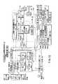
図12は、この発明の他の実施の形態に係る記録再生システム(光ディスク装置とSTB装置とが一体化されたストリームデータ記録再生装置)の構成を説明する図である。 FIG. 12 is a diagram for explaining the configuration of a recording / reproducing system (a stream data recording / reproducing apparatus in which an optical disc apparatus and an STB apparatus are integrated) according to another embodiment of the present invention.
この実施の形態におけるストリームデータ記録再生装置は、エンコーダ部401、デコーダ部402、STB部403、メインMPU404、V(ビデオ)ミキシング部405、フレームメモリ部406、キー入力部457、表示部458、情報媒体(DVD−RAMディスク等)201に対して情報記録あるいは情報再生を行なう記録再生部(ディスクドライブ部)409、データプロセサ(D−PRO)部410、一時記憶部411、A/V(オーディオ・ビデオ)入力部442、TVチューナ部443を備えている。また、デジタルTVの映像情報以外に、例えばMPEG4で圧縮されたTV電話の映像情報あるいはMD(ミディディスク)もしくはCD(コンパクトディスク)などのデジタルオーディオ情報などを入力し、ストリームデータとして情報媒体201上に記録することも可能とするために、デジタル信号入力部441を備えている。 The stream data recording / reproducing apparatus in this embodiment includes an encoder unit 401, a decoder unit 402, an
このストリームデータ記録再生装置はさらに、STB部403に接続された衛星アンテナ421、システムタイムカウンタ(STC)部424、ビデオミキシング部(Vミキシング部)405からパーソナルコンピュータ(PC)435へデジタルビデオ信号を送るインターフェイス(I/F)434、アナログTV437用D/A変換部436を備えている。 This stream data recording / reproducing apparatus further transmits a digital video signal from the
ここで、Vミキシング部405は、デコーダ部402のV−PRO部438からのデジタルビデオ信号と、STB部403からのデジタルビデオ信号453とを、適宜ミキシングする機能を持っている。このミキシング機能により、たとえばTV437の表示画面の左側にSTB部403からの放送画像を表示し、TV437の表示画面の右側にディスク201から再生した画像を表示することができる。あるいは、STB部403からの放送画像とディスク201からの再生画像とを、PC435のモニタ画面において、オーバーラッピングウインドウに重ねて表示することもできる。 Here, the V mixing unit 405 has a function of appropriately mixing the digital video signal from the V-PRO unit 438 of the decoder unit 402 and the digital video signal 453 from the
以上の構成において、エンコーダ部401内は、ビデオおよびオーディオ用のA/D変換部444、A/D変換部444からのデジタルビデオ信号、STB部403からのデジタルビデオ信号453あるいはデジタル信号入力部441からのデジタル信号を選択してビデオエンコード部446に送るセレクタ445、セレクタ445からのビデオ信号をエンコードするビデオエンコード部446、A/D変換部444からのオーディオ信号をエンコードするオーディオエンコード部447、TVチューナ部443からのクローズドキャプション(cc)信号あるいは文字放送信号等を副映像(SP)にエンコードするSPエンコード部448、フォーマッタ部449、一時的にデータを格納するためのバッファメモリ部450より構成される。 In the above configuration, the encoder unit 401 includes an A /
一方、デコーダ部402内は、メモリ426を内蔵する分離部425、縮小画像(サムネールピクチャ)生成部439を内蔵するビデオデコード部428、SPデコード部429、オーディオデコード部430、TSパケット(トランスポートパケット)転送部427、ビデオプロセサ(V−PRO)部438、オーディオ用D/A変換部432より構成されている。 On the other hand, in the decoder unit 402, a separating unit 425 incorporating a memory 426, a
オーディオデコード部430でデコードされたデジタルオーディオ信号は、インターフェイス(I/F)431を介して外部出力可能となっている。また、このデジタルオーディオ信号をD/A変換部432でアナログ化したアナログオーディオ信号により、外部のオーディオアンプ(図示せず)を介してスピーカ433が駆動されるようになっている。D/A変換部432は、オーディオデコード部430からのデジタルオーディオ信号のみならず、STB部403からのデジタルオーディオ信号452のD/A変換もできるように構成される。 The digital audio signal decoded by the
なお、ディスク201からの再生データをSTB部403に転送する場合は、TSパケット転送部427において分離部425からの再生データ(ビットストリーム)をトランスポートパケット(TSパケット)に変更し、STC424からの時間情報に転送時間を合わせて、TSパケットをSTB部403に送ればよい。 When the reproduction data from the
図12のメインMPU404は、作業用メモリとしてのワークRAM454aと、ストリームデータ作成制御部454bという名の制御プログラムと、ストリームデータ再生制御部454cという名の制御プログラムと、ストリームデータの部分消去/仮消去制御部454dという名の制御プログラム等を含んでいる。ストリームデータ記録再生装置における録画時の制御は、上記制御プログラム(シーケンシャルな制御プログラム)を用いメインMPU404により行われる。 The main MPU 404 in FIG. 12 includes a
ここで、ファイルの管理領域(図2あるいは図3(e)のナビゲーションRTR.IFO104、STREAM.IFO105)などを読み書きするために、メインMPU404は、D−PRO部410に、専用のマイクロコンピュータバスを介して接続されている。 Here, in order to read / write the file management area (navigation RTR.IFO104, STREAM.IFO105 in FIG. 2 or FIG. 3 (e)), the main MPU 404 connects the D-
まず、図12の装置における録画時のビデオ信号の流れについて説明をする。録画時には、メインMPU404内のストリームデータ作成制御部454bという名のシーケンシャルプログラムにしたがって、一連の処理が行われる。すなわち、IEEE1394規格に準拠した伝送経路経由してSTB部403からエンコーダ部401へ送出されたストリームデータは、まずフォーマッタ部449に転送される。フォーマッタ部449のIEEE1394受信側は、STC424のタイムカウント値に基づいて、ストリームデータ転送開始からの時間を読み込む。読み込んだ時間情報は、管理情報としてメインMPU404へ送られ、ワークRAM部454aに保存される。 First, the flow of video signals during recording in the apparatus of FIG. 12 will be described. At the time of recording, a series of processing is performed in accordance with a sequential program named stream data creation control unit 454b in main MPU 404. That is, stream data sent from the
メインMPU404は、上記時間情報に基づいて、ストリームデータをストリームブロック毎(ビデオレコーダではVOBU毎、ストリーマではSOBU毎)に切り分ける区切れ情報を作成するとともに、この区切れ情報に対応したセルの切り分け情報およびプログラムの切り分け情報、さらにはPGCの切り分け情報を作成し、メインMPU404内のワークRAM部454aに逐次記録する。 Based on the time information, the main MPU 404 creates delimiter information for segmenting the stream data for each stream block (for each VOBU for a video recorder and for each SOBU for a streamer), and cell segmentation information corresponding to the segment information. And program segmentation information, and further PGC segmentation information are created and sequentially recorded in the
フォーマッタ部449は、メインMPU404のストリームデータ作成制御部454bからの指示にしたがって、STB部403から送られてきたストリームデータをストリームパックの列に変換し、変換されたストリームパック列をD−PRO部410へ入力する。入力されたストリームパックはセクタと同じ2048バイトの一定サイズを持っている。D−PRO部410は、入力されたストリームパックを16セクタ毎にまとめてECCブロックにして、ディスクドライブ部409へ送る。ディスクドライブ部409では、データ記録を行なうに適した変調処理が施され、図示しない光学ヘッドを介して媒体201へ記録が行われるようになっている。 The formatter unit 449 converts the stream data sent from the
ディスクドライブ部409においてDVD−RAMディスク(情報媒体)201への記録準備ができていない場合には、D−PRO部410は、記録データを一時記憶部411に転送して一時保存し、ディスクドライブ部409においてデータ記録準備ができるまで待つ。ディスクドライブ部409において記録準備ができた段階で、D−PRO部410は一時記憶部411に保存されたデータをディスクドライブ部409に転送する。これにより、ディスク201への記録が開始される。一時記憶部411に保存されたデータの記録が済むと、その続きのデータはフォーマッタ部449からD−PRO部410へシームレスに転送されるようになっている。ここで、一時記憶部411は、高速アクセス可能で数分以上の記録データを保持できるようにするため、大容量メモリを想定している。 When the disk drive unit 409 is not ready for recording on the DVD-RAM disk (information medium) 201, the D-
次に、再生時のデータ処理について説明する。ストリームデータ記録再生装置における再生時の制御は、ストリームデータ再生制御部454cという名のシーケンシャルプログラムにしたがい、メインMPU404によって、一連の処理が行われる。まず、ディスクドライブ部409により、RAMディスク(情報媒体)201からストリームデータが再生される。再生されたストリームデータは、D−PRO部409を経由してデコーダ部402に転送される。 Next, data processing during reproduction will be described. Control during playback in the stream data recording / playback apparatus is performed by the main MPU 404 in accordance with a sequential program named stream data playback control unit 454c. First, stream data is reproduced from the RAM disk (information medium) 201 by the disk drive unit 409. The reproduced stream data is transferred to the decoder unit 402 via the D-PRO unit 409.
デコーダ部402内部では、再生されたストリームデータ中のトランスポートパケットを分離部425が受け取る。分離部425は、ストリームID/サブストリームIDに従って、ビデオパケットデータ(MPEGビデオデータ)はビデオデコード部428へ転送し、オーディオパケットデータはオーディオデコード部430へ転送し、副映像パケットデータはSPデコード部429へ転送する。 In the decoder unit 402, the separation unit 425 receives the transport packet in the reproduced stream data. The separation unit 425 transfers video packet data (MPEG video data) to the
ビデオデコード部428でデコードされたビデオデータは、Vミキシング部405およびD/A変換部436を介してアナログTV信号に変換され、TV437に転送されて画像表示される。同時に、オーディオデコード部430でデコードされたオーディオ信号もD/A変換部432へ送られ、デジタル音声データに変換される。変換されたデジタル音声データは、I/F431を介して外部オーディオ機器(図示せず)のデジタル入力に転送される。あるいは、変換されたデジタル音声データは、D/A変換部432によりアナログ音声信号に変換され、図示しないオーディオアンプを介して、スピーカ433に送られる。 The video data decoded by the
図12に示したストリームデータ記録再生装置では、ディスクドライブ部409とSTB部403とが一体化された構成を採っているため、図9のようなデータ転送インターフェイス部414、420を持たない。また、STC部424というシステム全体に共通の基準クロック発生部を持っているため、モディファイドタイムスタンプで示されるようなタイムスタンプの付け替え処理が不要となる。またデジタル信号入力部441を持っているため、デジタルTVの映像情報以外の例えばMPEG4で圧縮されたTV電話の映像情報やMD(ミディディスク)やCD(コンパクトディスク)などのPCMオーディオ情報などを入力し、ストリームデータとして情報媒体201上に記録することもできる。 The stream data recording / reproducing apparatus shown in FIG. 12 has a configuration in which the disk drive unit 409 and the
なお、モディファイドタイムスタンプで示されるようなタイムスタンプの付け替え処理が不要とはいっても、ストリーム記録時において、「SOB内の最初のパックに対してストリーマ内部のローカル基準クロックをそのパック内で開始する最初のアプリケーションパケットのAPATに等しくする」ことは必要である。 Although the time stamp replacement process as shown by the modified time stamp is unnecessary, at the time of stream recording, “the local reference clock in the streamer is started within the pack for the first pack in the SOB. It is necessary to make it equal to the APAT of the first application packet.
図12の装置において、再生が行われる場合には、図示しない光学ヘッドを介して情報媒体201の記録データが読み取られる。記録再生部409ではその復調処理が行われ、復調されたデータはD−PRO部410に入力され、エラー訂正処理等が施される。復調されたデータは、多重化情報分離部425に入力される。この多重化情報分離部425では、図9で説明したのと同様な信号処理が行われる。ビデオデコード部428には、縮小画面生成部439(図9では代表画像生成部と称した)が設備されているが、これは、例えば編集用や見出し用の画像を生成する部分である。 In the apparatus of FIG. 12, when reproduction is performed, the recording data of the
図13は、この発明の他の実施の形態に係るストリームデータ記録手順(ショートアプリケーションヘッダ利用)を説明するフローチャート図である。たとえば図12のデジタル信号入力部441からデジタルストリームデータが入力される(ステップS11)。入力されたストリームデータに対して、図12のフォーマッタ部449において、STC424が発生する基準クロックに合わせて、アプリケーションパケット毎に、タイムスタンプが生成される(ステップS12)。この処理と並行して、メインMPU部454により、入力されたストリームデータの内容が判別され(ステップS13)、判別された内容に応じてショートアプリケーションヘッダの設定が行なわれる(ステップS14)。 FIG. 13 is a flowchart for explaining a stream data recording procedure (using a short application header) according to another embodiment of the present invention. For example, digital stream data is input from the digital signal input unit 441 in FIG. 12 (step S11). For the input stream data, the formatter unit 449 in FIG. 12 generates a time stamp for each application packet in accordance with the reference clock generated by the STC 424 (step S12). In parallel with this process, the
ステップS12で生成されるタイムスタンプが示す時間は、前述したアプリケーションパケット到着時間APATに相当する。つまり、SOB内の最初のパックに対して、ストリーマ内部のローカル基準クロック(図5のSCR303または後述する図15のSCRベースに対応)が、そのパック内で開始する最初のアプリケーションパケットのAPATに等しくなる。 The time indicated by the time stamp generated in step S12 corresponds to the application packet arrival time APAT described above. That is, for the first pack in the SOB, the local reference clock inside the streamer (corresponding to the
図13のその後の処理(ステップS15〜ステップS18)は、ステップST17で記録されるアプリケーションヘッダがショートアプリケーションヘッダであることを除き、図10を参照して説明したステップS6〜ステップS9の処理と同様である。 The subsequent processing in FIG. 13 (steps S15 to S18) is the same as the processing in steps S6 to S9 described with reference to FIG. 10 except that the application header recorded in step ST17 is a short application header. It is.
図14は、この発明の一実施の形態に係るデータ構造において、とくにデータエリア内のデータ構造を説明する図である。図14には、図1(c)のデータエリア(21〜23)に配置されるデータの構成がさらに詳しく例示されている。 FIG. 14 is a diagram for explaining the data structure in the data area, in particular, in the data structure according to the embodiment of the present invention. FIG. 14 illustrates in more detail the configuration of data arranged in the data areas (21 to 23) in FIG.
図14の最上段に示すデータエリアには、図14の2段目に示すように、モディファイドタイムスタンプとアプリケーションパケットとの組が複数存在する。このアプリケーションパケット内には、図14の3段目に示すように、アプリケーションパケットヘッダとペイロードとの組が複数格納される。複数のペイロードからデータを集めると、図14の4段目に例示するように、Iピクチャ、Bピクチャ、Pピクチャのデータ集合体となる。ここで、Iピクチャのデータ部を見ると、図14の5段目に示すように、ピクチャヘッダ、圧縮情報等が存在する。また、ピクチャヘッダの内部を見ると、図14の最下段に示すように、ヘッダID、ピクチャIDなどが存在する。 In the data area shown at the top of FIG. 14, there are a plurality of sets of modified time stamps and application packets, as shown at the second stage of FIG. In this application packet, as shown in the third row of FIG. 14, a plurality of sets of application packet headers and payloads are stored. When data is collected from a plurality of payloads, a data aggregate of I picture, B picture, and P picture is obtained as illustrated in the fourth row of FIG. Here, looking at the data part of the I picture, as shown in the fifth row of FIG. 14, there are a picture header, compression information, and the like. When the inside of the picture header is viewed, there are a header ID, a picture ID, and the like as shown at the bottom of FIG.
なお、図示しないが、プレゼンテーションタイムスタンプPTSは、図9のメモリ部426からビデオデコード部428へパケットを送るタイミングを示している。システムタイムカウンタ(システムクロック)STC部424の値がPTSの値に一致したとき、または所定の大きな値となったときに、図14のIピクチャ情報がビデオデコード部428に送られ、ビデオデコード部428は図示しないデコードタイムスタンプDTSのタイミングで、送られてきたIピクチャ情報のデコードを開始するようになっている。 Although not shown, the presentation time stamp PTS indicates the timing of sending a packet from the memory unit 426 of FIG. 9 to the
ここで、たとえば図9の光ディスク装置415とSTB装置416との間で同期ずれがあると、PTSに基いてメモリ部426からビデオデコード部428へ送られるデータ転送量と、光ディスク装置415からメモリ部426へ送られてくるデータ量の不整合(アンマッチング)が生じる。このような不具合を取り除くために、図9の装置では、次のような機能が設けられている。 Here, for example, if there is a synchronization error between the optical disk device 415 and the STB device 416 of FIG. 9, the amount of data transferred from the memory unit 426 to the
たとえばアプリケーションパケットの特定個数(例えば1万個、あるいは10万個)を送信/受信する毎に、光ディスク装置とSTB装置側とで、その送信時刻/受信時刻を一時記憶部411、ワークRAMメモリ部407に記憶する。これにより、両者には、アプリケーションパケットを特定個数を送信/受信する毎の時刻情報テーブルを作成することができる。ここで、適当な時間間隔たとえば10分、あるいは30分間隔(この時間間隔は任意に修正できるようにしてもよい)で、STB装置側から、光ディスク装置側へ時刻情報テーブルを転送する。光ディスク装置側では、両者の時刻情報テーブルを比較し、時刻のずれ情報を把握する。そうすれば、アプリケーションパケットの特定個数毎に、双方の装置間でどのくらいの時間ずれ(同期ずれ)が生じているのかを把握することができる。この同期ずれ量に応じて、光ディスク装置415側のデータ再生速度あるいは、データの転送タイミングの調整を行なうことができる。 For example, every time a specific number of application packets (for example, 10,000 or 100,000) is transmitted / received, the optical disk device and the STB device side indicate the transmission time / reception time of the temporary storage unit 411 and the work RAM memory unit. Store in 407. Thus, a time information table can be created for each time a specific number of application packets are transmitted / received. Here, the time information table is transferred from the STB device side to the optical disk device side at an appropriate time interval, for example, 10 minutes or 30 minutes (this time interval may be arbitrarily modified). On the optical disc apparatus side, both time information tables are compared to grasp time lag information. Then, for each specific number of application packets, it is possible to grasp how much time deviation (synchronization deviation) occurs between both apparatuses. The data reproduction speed on the optical disk device 415 side or the data transfer timing can be adjusted according to the amount of synchronization deviation.
データの転送タイミングを制御する手段の例としては、前述したモディファイドタイムスタンプを、実際に使用する前に図示しない変換テーブルを通して使用する方法がある。時間調整手段としては、その調整量に応じて各種の方法が可能である。この調整手段は、情報媒体201に対するデータ記録が、別の光ディスク装置によってなされている場合に有効である。実際にデータを再生する装置の基準クロックと実際にデータ記録した装置の基準クロックとの間に周波数ずれがあると、再生されたモディファイドタイムスタンプの値が、再生する装置の予期しているモディファイドタイムスタンプの値とずれている場合があるからである。 As an example of means for controlling the data transfer timing, there is a method of using the above-mentioned modified time stamp through a conversion table (not shown) before actually using it. Various methods can be used as the time adjustment means depending on the adjustment amount. This adjustment means is effective when data recording on the
以上説明したこの発明の実施の形態における効果をまとめると以下のようになる。 The effects of the embodiment of the present invention described above are summarized as follows.
*情報媒体に記録するストリームデータの内容(種類)に応じて最適なアプリケーションヘッダタイプ(ロングかショートか)を選択するため、アプリケーションヘッダ情報として不要な情報を記録する必要がない。その結果、情報媒体上に記録する情報の記録効率を向上させ、情報媒体に対する実質的な有効記録容量を増加させることができる。 * Since an optimum application header type (long or short) is selected according to the content (type) of stream data to be recorded on the information medium, it is not necessary to record unnecessary information as application header information. As a result, it is possible to improve the recording efficiency of information recorded on the information medium and increase the effective effective recording capacity for the information medium.
*IEEE1394などで転送されてくるストリームデータに対して、ストリーマ内部の基準クロックでタイムスタンプを付け直し、さらにその基準クロックに基づき各ストリームパック先頭位置での時刻情報をシステムクロック(SCR)としてストリームパック内に記録することができる。こうすることで、
(a)ストリームデータを読み飛ばしながら再生する場合にストリームパック内に記録されたシステムクロック(SCR)に合わせてストリーマの基準クロックをリセットし、そのリセットしたストリーマ内の基準クロックを基準にしてタイムスタンプ情報のタイミングに合わせて各アプリケーションパケットを出力することができる。このようにストリームパック内に記録されたシステムクロック(SCR)で常にリセットすると、情報媒体上に点在するストリームデータをランダムかつ断続的に再生しても安定に各アプリケーションパケット間の出力タイミングを保持できる。* Restreaming the stream data transferred by IEEE 1394, etc. with the reference clock inside the streamer, and using the reference clock, the time information at the head position of each stream pack is used as the system clock (SCR). Can be recorded within. By doing this,
(A) When stream data is reproduced while skipping, the streamer reference clock is reset in accordance with the system clock (SCR) recorded in the stream pack, and the time stamp is set based on the reset reference clock in the streamer. Each application packet can be output in accordance with the timing of information. If the system clock (SCR) recorded in the stream pack is always reset in this way, the output timing between each application packet is stably maintained even if the stream data scattered on the information medium is reproduced randomly and intermittently. it can.
(b)タイムスタンプの値を用いて情報媒体上に記録されたストリームデータを検索する場合、いちいちタイムスタンプまで再生せずにストリームパック内に記録されたシステムクロック(SCR)の値を再生するだけで(見出しとして活用して)粗いアクセスを行うことができる。 (B) When retrieving stream data recorded on an information medium using a time stamp value, only the system clock (SCR) value recorded in the stream pack is reproduced without reproducing the time stamp. Can be used for rough access (use as a headline).
(c)再生時にストリームパック内に記録されたシステムクロック(SCR)の値とタイムスタンプの値を比較することで、現在再生中のストリームデータが本来再生したいデータであるかどうかの確認を、リアルタイムで行うことができる。 (C) By comparing the value of the system clock (SCR) recorded in the stream pack at the time of reproduction with the value of the time stamp, it is possible to confirm whether the currently reproduced stream data is the data to be reproduced in real time. Can be done.
*光ディスク装置からSTB装置側へ転送されるデータが適切な量となるように、装置間の同期を管理することができる。 * Synchronization between devices can be managed so that the amount of data transferred from the optical disk device to the STB device becomes an appropriate amount.
図15は、ストリームパックのデータ構造を説明する図である。各ストリームパックは、図15(b)に示すようなデータ構造を持っている。すなわち、14バイトのパックヘッダと、6バイトのPESヘッダと、1バイトのサブストリームIDと、9バイトのアプリケーションヘッダと、必要に応じて用いられるオプションのアプリケーションヘッダエクステンションと、必要に応じて用いられるオプションのスタッフィングバイトと、アプリケーションタイムスタンプATSが付されたアプリケーションパケットを1以上含むアプリケーションパケット群とで、1つのストリームパックが構成される。 FIG. 15 is a diagram for explaining the data structure of a stream pack. Each stream pack has a data structure as shown in FIG. That is, a 14-byte pack header, a 6-byte PES header, a 1-byte substream ID, a 9-byte application header, an optional application header extension that is used as necessary, and an optional application header extension. One stream pack is composed of an optional stuffing byte and an application packet group including one or more application packets with an application time stamp ATS.
図15(b)のパックヘッダは、図15(e)に示すように、パック開始コードの情報、システムクロックリファレンス(SCR)ベースの情報、SCRエクステンションの情報、プログラム多重化レートの情報、パックスタッフィング長の情報等を含んでいる。SCRベースは32ビットで構成され、その32ビット目はゼロとされる。また、プログラム多重化レートとしては、たとえば10.08Mbpsが採用される。 As shown in FIG. 15E, the pack header in FIG. 15B includes pack start code information, system clock reference (SCR) base information, SCR extension information, program multiplexing rate information, pack stuffing. Includes length information. The SCR base is composed of 32 bits, and the 32nd bit is set to zero. Further, for example, 10.08 Mbps is adopted as the program multiplexing rate.
図15(b)のPESヘッダは、図15(d)に示すように、パケット開始コードプリフィックスの情報、ストリームID(プライベートストリーム2)の情報、PESパケット長の情報を含んでいる。このサブストリームIDは、図15(d)に示すように、ストリーム記録データを特定する内容を持つ。具体的には、サブストリームID=”00000010b”によって、そのストリームパックに格納されたデータがストリーム記録データであることが示される。このストリームIDが”10111110b”のときは、そのストリームパックがパディングパケットに用いられるものであることが示される。 As shown in FIG. 15D, the PES header in FIG. 15B includes packet start code prefix information, stream ID (private stream 2) information, and PES packet length information. As shown in FIG. 15D, the substream ID has contents for specifying stream recording data. Specifically, substream ID = “00000010b” indicates that the data stored in the stream pack is stream recording data. When this stream ID is “10111110b”, it is indicated that the stream pack is used for a padding packet.
図15(b)のアプリケーションヘッダは、図15(a)に示すように、バージョン情報、アプリケーションパケット数AP_Ns、先頭アプリケーションパケットのタイムスタンプ位置FIRST_AP_OFFSET、エクステンションヘッダ情報EXTENSION_HEADER_IFO、サービスID等を含んでいる。 As shown in FIG. 15A, the application header in FIG. 15B includes version information, the number of application packets AP_Ns, the time stamp position FIRST_AP_OFFSET of the first application packet, extension header information EXTENSION_HEADER_IFO, a service ID, and the like.
ここで、バージョンには、アプリケーションヘッダフォーマットのバージョン番号が記述される。 Here, the version describes the version number of the application header format.
アプリケーションヘッダのAP_Nsは、該当ストリームパック内で開始するアプリケーションパケットの数を記述したものである。該当ストリームパック内にATSの先頭バイトが格納されているときは、このストリームパック内でアプリケーションパケットが開始すると見なすことができる。 AP_Ns in the application header describes the number of application packets that start in the corresponding stream pack. When the first byte of ATS is stored in the corresponding stream pack, it can be considered that the application packet starts in this stream pack.
FIRST_AP_OFFSETには、該当ストリームパケット内で開始される最初のアプリケーションパケットのタイムスタンプ位置が、このストリームパケットの最初のバイトからの相対値として、バイト単位で、記述される。もしストリームパケット内で開始するアプリケーションパケットがないときは、FIRST_AP_OFFSETには「0」が記述される。 In FIRST_AP_OFFSET, the time stamp position of the first application packet started in the corresponding stream packet is described in byte units as a relative value from the first byte of this stream packet. If there is no application packet to start in the stream packet, “0” is described in FIRST_AP_OFFSET.
EXTENSION_HEADER_INFOには、該当ストリームパケット内にアプリケーションヘッダエクステンションおよび/またはスタッフィングバイトが存在するか否かが、記述される。EXTENSION_HEADER_INFOの内容が00bの場合は、アプリケーションヘッダの後にアプリケーションヘッダエクステンションもスタッフィングバイトも存在しないことが示される。EXTENSION_HEADER_INFOの内容が10bの場合は、アプリケーションヘッダの後にアプリケーションヘッダエクステンションがあるが、スタッフィングバイトは存在しないことが示される。EXTENSION_HEADER_INFOの内容が11bの場合は、アプリケーションヘッダの後にアプリケーションヘッダエクステンションが存在し、かつアプリケーションヘッダエクステンションの後にスタッフィングバイトも存在することが示される。EXTENSION_HEADER_INFOの内容が01bとなることは禁止されている。 EXTENSION_HEADER_INFO describes whether an application header extension and / or stuffing byte is present in the corresponding stream packet. When the content of EXTENSION_HEADER_INFO is 00b, it indicates that neither an application header extension nor a stuffing byte exists after the application header. When the content of EXTENSION_HEADER_INFO is 10b, it indicates that there is an application header extension after the application header, but there is no stuffing byte. When the content of EXTENSION_HEADER_INFO is 11b, it is indicated that an application header extension exists after the application header, and a stuffing byte also exists after the application header extension. It is prohibited for the content of EXTENSION_HEADER_INFO to be 01b.
アプリケーションパケットエリアの前のスタッフィングバイト(オプション)は、「EXTENSION_HEADER_INFO=11b」によりアクティブになる。こうすることで、アプリケーションヘッダエクステンション内のバイト数と、アプリケーションパケットエリア内に格納できるアプリケーションパケット数との間に矛盾が生じた場合に「パッキングパラドクス」が起きるのを防止できる。 The stuffing byte (option) in front of the application packet area is activated by “EXTENSION_HEADER_INFO = 11b”. By doing so, it is possible to prevent a “packing paradox” from occurring when there is a contradiction between the number of bytes in the application header extension and the number of application packets that can be stored in the application packet area.
SERVICE_IDには、ストリームを生成するサービスのIDが記述される。このサービスが未知のものであれば、SERVICE_IDに0x0000が記述される。 SERVICE_ID describes the ID of the service that generates the stream. If this service is unknown, 0x0000 is described in SERVICE_ID.
図15(b)のスタッフィングバイトおよびアプリケーションパケット群は、アプリケーションパケットエリアを構成している。このアプリケーションパケットエリアの先頭部分は、図15(b)のストリームパケットに対して先行するストリームパケットから跨るアプリケーションパケットの一部(部分パケット)を適宜含むことができる。その後に、アプリケーションタイムスタンプATSとアプリケーションパケットとのペアが複数ペア、シーケンシャルに記録できる。そして、アプリケーションパケットエリアの末尾部分は、図15(b)のストリームパケットに対して後続するストリームパケットへ跨るアプリケーションパケットの一部(部分パケット)、あるいは予約されたバイト数のスタッフィングエリアを適宜含むことができる。 The stuffing byte and application packet group shown in FIG. 15B constitute an application packet area. The head part of the application packet area can appropriately include a part (partial packet) of the application packet straddling the stream packet preceding the stream packet of FIG. Thereafter, a plurality of pairs of application time stamp ATS and application packet can be recorded sequentially. The end portion of the application packet area appropriately includes a part of the application packet (partial packet) straddling the stream packet subsequent to the stream packet of FIG. 15B, or a stuffing area having the reserved number of bytes. Can do.
別の言い方をすると、アプリケーションパケットエリアの開始位置には、部分アプリケーションパケットが存在でき、アプリケーションパケットエリアの終了位置には、部分アプリケーションパケットあるいは予約されたバイト数のスタッフィングエリアが存在できる。 In other words, a partial application packet can exist at the start position of the application packet area, and a partial application packet or a stuffing area with the reserved number of bytes can exist at the end position of the application packet area.
各アプリケーションパケットの前に配置されたアプリケーションタイムスタンプ(ATS)は、32ビット(4バイト)で構成される。このATSは、2つの部分、すなわち基本部分と拡張部分に分けられる。基本部分は90kHzユニット値と呼ばれる部分であり、拡張部分は27MHzで測った細かい値(less significant value)を示す。 An application time stamp (ATS) arranged in front of each application packet is composed of 32 bits (4 bytes). This ATS is divided into two parts: a basic part and an extended part. The basic part is a part called 90 kHz unit value, and the extended part shows a less significant value measured at 27 MHz.
図15(b)において、アプリケーションヘッダエクステンションは、アプリケーションパケット〜アプリケーションパケット間で異なり得る情報を格納することに用いることができる。このような情報は、必ずしも全てのアプリケーションに必要なものではない。それゆえ、アプリケーションヘッダのデータフィールドは、ストリームデータエリア内にオプションのアプリケーションヘッダエクステンションが存在することを(前述したEXTENSION_HEADER_INFOにおいて)記述できるように定義されいる。 In FIG. 15B, the application header extension can be used to store information that may differ between application packets and application packets. Such information is not necessary for all applications. Therefore, the data field of the application header is defined so as to describe (in the above-described EXTENSION_HEADER_INFO) that an optional application header extension exists in the stream data area.
ストリームの記録時において、最初のアプリケーションパケットのアプリケーションタイムスタンプATSの先頭バイトは、ストリームオブジェクトSOBの始まりにおける最初のストリームパケット内のアプリケーションパケットエリアの開始位置に、アラインされている必要がある。 At the time of recording the stream, the first byte of the application time stamp ATS of the first application packet needs to be aligned with the start position of the application packet area in the first stream packet at the beginning of the stream object SOB.
一方、SOB内のその後のストリームパケットについては、隣接ストリームパケット境界で、アプリケーションパケットが分割(スプリット)されてもよい。図15(b)に示した部分パケットは、この分割(スプリット)により生じたアプリケーションパケットを示している。 On the other hand, for subsequent stream packets in the SOB, application packets may be divided (split) at adjacent stream packet boundaries. The partial packet shown in FIG. 15B shows an application packet generated by this division (split).
ストリームパケット内で開始される最初のアプリケーションタイムスタンプのバイトオフセット、およびそのストリームパケット内で開始されるアプリケーションパケットの数は、そのアプリケーションヘッダに記述される。こうすることにより、あるストリームパケット内において、最初のアプリケーションタイムスタンプの前および最後のアプリケーションパケットの後におけるスタッフィングが、自動的に行われる。すなわち、上記自動化メカニズムにより、「アプリケーションが自分でスタッフィングを行なう」ことが実現される。この自動スタッフィングにより、ストリームパケットは常に必要な長さを持つことになる。 The byte offset of the first application timestamp that starts in the stream packet and the number of application packets that start in the stream packet are described in the application header. By doing so, stuffing before the first application time stamp and after the last application packet is automatically performed in a stream packet. That is, “the application performs stuffing by itself” is realized by the automatic mechanism. This automatic stuffing ensures that the stream packet always has the required length.
アプリケーションヘッダエクステンション(オプション)はエントリのリストからなる。ここには、該当ストリームパケット内で開始する各アプリケーションパケットに対する1バイト長の1エントリがある。これらエントリのバイトは、アプリケーションパケット毎に異なり得る情報を格納することに利用できる。 The application header extension (optional) consists of a list of entries. Here, there is one entry of 1 byte length for each application packet starting in the corresponding stream packet. The bytes of these entries can be used to store information that can vary from application packet to application packet.
なお、1バイトのアプリケーションヘッダエクステンション(オプション)には、図15(c)に示すように、1ビットのAU_STARTと、1ビットのAU_ENDと、2ビットのCOPYRIGHTとを記述できるようになっている。AU_STARTが”1”にセットされると、関連アプリケーションパケットが、ストリーム内にランダムアクセスエントリポイント(ランダムアクセスユニットの開始)を含むことが示される。AU_ENDが”1”にセットされると、関連アプリケーションパケットがランダムアクセスユニットの最終パケットであることが示される。COPYRIGHTには、関連アプリケーションパケットの著作権の状態が記述される。 In the 1-byte application header extension (option), as shown in FIG. 15C, 1-bit AU_START, 1-bit AU_END, and 2-bit COPYRIGHT can be described. When AU_START is set to “1”, it indicates that the associated application packet includes a random access entry point (start of random access unit) in the stream. When AU_END is set to “1”, it indicates that the associated application packet is the final packet of the random access unit. COPYRIGHT describes the copyright status of the related application packet.
図15のパケット構造は、該当ストリームオブジェクト(SOB)の最終セクタ以外に適用できるが、その最終セクタには必ずしも適用されない。SOBの情報記録が行われないような最終セクタに対しては、アプリケーションパケットエリアが1つのATSとゼロバイトで埋められたスタッフィングパケット(先頭のスタッフィングパケット)、あるいはアプリケーションパケットエリアがゼロバイトで埋められたスタッフィングパケット(後続のスタッフィングパケット)が適用される。 The packet structure of FIG. 15 can be applied to other than the last sector of the corresponding stream object (SOB), but is not necessarily applied to the last sector. For the last sector where SOB information is not recorded, the application packet area is filled with one ATS and zero bytes (the first stuffing packet), or the application packet area is filled with zero bytes. Stuffing packets (subsequent stuffing packets) are applied.
図15のデータ構造の特徴を纏めると、たとえば次のようになる。すなわち、記録されたビットストリームに対する再生データを表すストリームオブジェクト(SOB)が1以上集まってストリームデータが構成される。前記ストリームオブジェクト(SOB)が1以上のストリームパック(S_PCK)で構成される。前記ストリームパック(S_PCK)はパックヘッダとストリームパケット(S_PKT)とで構成される。前記パックヘッダは所定の時間情報(SCR)を含む。前記ストリームパケット(S_PKT)は所定のタイムスタンプ(ATS)が付されたアプリケーションパケット(AP_PKT)を1以上含む。そして、前記ストリームオブジェクト(SOB)の記録中に(ストリーマに)入ってくる前記アプリケーションパケット(AP_PKT)が、前記所定の時間情報(SCR)に対応した(ストリーマ内部の)ローカル基準クロック(図9の440)によりタイムスタンプされ(図14のモディファイドタイムスタンプ;図15のATS)、前記タイムスタンプの情報が前記ストリームパック(S_PCK)内に記録される。 The characteristics of the data structure of FIG. 15 are summarized as follows, for example. That is, one or more stream objects (SOB) representing reproduction data for the recorded bit stream are collected to form stream data. The stream object (SOB) is composed of one or more stream packs (S_PCK). The stream pack (S_PCK) is composed of a pack header and a stream packet (S_PKT). The pack header includes predetermined time information (SCR). The stream packet (S_PKT) includes one or more application packets (AP_PKT) with a predetermined time stamp (ATS). Then, the application packet (AP_PKT) that enters (to the streamer) during recording of the stream object (SOB) is a local reference clock (in the streamer) corresponding to the predetermined time information (SCR) (in FIG. 9). 440) (the modified time stamp in FIG. 14; ATS in FIG. 15), and the time stamp information is recorded in the stream pack (S_PCK).
前記ストリームパケットはアプリケーションヘッダを持ち、前記ストリームパケット内の最初に記録されているタイムスタンプの位置情報(FIRST_AP_OFFSET)が前記アプリケーションヘッダ内に含まれる。 The stream packet has an application header, and position information (FIRST_AP_OFFSET) of a time stamp recorded first in the stream packet is included in the application header.
前記ストリームオブジェクト(SOB)を情報媒体(201)に記録するときは、(ストリーマに)入ってくる前記アプリケーションパケット(AP_PKT)が、前記所定の時間情報(SCR)に対応した(ストリーマ内部の)ローカル基準クロック(図9の440)によりタイムスタンプされ(図10のS4のモディファイドタイムスタンプ;図21〜図23ではST106、ST212、ST312のタイムスタンプ)、前記タイムスタンプの情報が前記ストリームパック(S_PCK)内に記録される。 When the stream object (SOB) is recorded on the information medium (201), the incoming application packet (AP_PKT) (in the streamer) corresponds to the predetermined time information (SCR) (in the streamer). Time stamped by the reference clock (440 in FIG. 9) (modified time stamp in S4 in FIG. 10; time stamps in ST106, ST212, and ST312 in FIGS. 21 to 23), the time stamp information is the stream pack (S_PCK). Recorded in.
図16は、ストリーマの管理情報(図2または図3のSTREAM.IFOに対応)の内部データ構造を説明する図である。図2あるいは図3(e)に示した管理情報(ナビゲーションデータ)であるSTREAM.IFO(SR_MANGR.IFO)105は、図16に示すように、ストリーマ情報STRIを含んでいる。 16 is a diagram for explaining the internal data structure of streamer management information (corresponding to the STREAM.IFO in FIG. 2 or FIG. 3). The management information (navigation data) shown in FIG. 2 or FIG. The IFO (SR_MANGR.IFO) 105 includes streamer information STRI as shown in FIG.
このストリーマ情報STRIは、図3(f)あるいは図16に示すように、ストリーマビデオマネージャ情報STR_VMGIと、ストリームファイル情報テーブルSFITと、オリジナルPGC情報ORG_PGCI(より一般的に表現すればPGC情報PGCI#i)と、ユーザ定義PGC情報テーブルUD_PGCITと、テキストデータマネージャTXTDT_MGと、アプリケーションプライベートデータマネージャAPDT_MGとで、構成されている。 As shown in FIG. 3 (f) or FIG. 16, this streamer information STRI includes streamer video manager information STR_VMGI, stream file information table SFIT, original PGC information ORG_PGCI (more generally, PGC information PGCI # i ), A user-defined PGC information table UD_PGCIT, a text data manager TXTDT_MG, and an application private data manager APDT_MG.
ストリーマビデオマネージャ情報STR_VMGIは、図16に示すように、STRI、STR_VMGIに関する管理情報等が記述されたビデオマネージャ情報管理情報VTSI_MATと、ストリーム内のプレイリストをサーチするためのサーチポインタが記述されたプレイリストサーチポインタテーブル(PL_SRPT)とを含んでいる。ここで、プレイリストとは、プログラムの一部のリストである。このプレイリストにより、(プログラムの内容に対して)任意の再生シーケンスをユーザが定義できる。ストリームファイル情報テーブルSFITは、ストリーマ動作に直接関係する全てのナビゲーションデータを含むものである。ストリームファイル情報テーブルSFITの詳細については、図18を参照して後述する。 As shown in FIG. 16, the streamer video manager information STR_VMGI includes video manager information management information VTSI_MAT in which management information on STR and STR_VMGI is described, and a play in which a search pointer for searching a playlist in the stream is described. A list search pointer table (PL_SRPT). Here, the play list is a list of a part of the program. This playlist allows the user to define any playback sequence (relative to the program content). The stream file information table SFIT includes all navigation data directly related to the streamer operation. Details of the stream file information table SFIT will be described later with reference to FIG.
オリジナルPGC情報ORG_PGCIは、オリジナルPGC(ORG_PGC)に関する情報を記述した部分である。ORG_PGCはプログラムセットを記述したナビゲーションデータを示す。ORG_PGCはプログラムの連なり(チェーン)であり、「〜.SRO」ファイル(図2ではSR_TRANS.SRO106)内に記録されたストリームデータを含む。 The original PGC information ORG_PGCI is a part describing information related to the original PGC (ORG_PGC). ORG_PGC indicates navigation data describing a program set. ORG_PGC is a series (chain) of programs, and includes stream data recorded in the “˜.SRO” file (
ここで、プログラムセットとは、情報媒体201の記録内容全体(全てのプログラム)を示すものである。プログラムセットの再生においては、任意のプログラムが編集されオリジナル記録に対してその再生順序が変更されている場合を除き、再生順序としてはそのプログラムの記録順序と同じ再生順序が用いられる。このプログラムセットは、オリジナルPGC(ORG_PGC)と呼ばれるデータ構造に対応している。 Here, the program set indicates the entire recorded contents (all programs) of the
また、プログラムは、ユーザにより認識されあるいはユーザにより定義されるところの、記録内容の論理単位である。プログラムセット中のプログラムは、1以上のオリジナルセルにより構成される。プログラムはオリジナルPGC内でのみ定義されるものである。さらに、セルは、プログラムの一部を示すデータ構造である。オリジナルPGC内のセルは「オリジナルセル」と呼ばれ、後述するユーザ定義PGC内のセルは「ユーザ定義セル」と呼ばれる。プログラムセット内の各々のプログラムは、少なくとも1個のオリジナルセルで構成される。また、各々のプレイリスト中のプログラムの一部それぞれは、少なくとも1個のユーザ定義セルで構成される。 A program is a logical unit of recorded content that is recognized by a user or defined by a user. A program in the program set is composed of one or more original cells. The program is defined only in the original PGC. Furthermore, the cell is a data structure indicating a part of the program. The cells in the original PGC are called “original cells”, and the cells in the user-defined PGC described later are called “user-defined cells”. Each program in the program set consists of at least one original cell. In addition, each part of the program in each playlist is composed of at least one user-defined cell.
一方、ストリーマでは、ストリームセル(SC)だけが定義される。各ストリームセルは、記録されたビットストリームの一部を参照するものである。この発明の実施の形態においては、特に断りなく「セル」と述べた場合は、「ストリームセル」のことを意味している。 On the other hand, in the streamer, only the stream cell (SC) is defined. Each stream cell refers to a part of the recorded bit stream. In the embodiment of the present invention, the term “cell” means “stream cell” unless otherwise specified.
なお、プログラムチェーン(PGC)とは、上位概念的な単位を示す。オリジナルPGCでは、PGCはプログラムセットに対応したプログラムの連なり(チェーン)を指す。また、ユーザ定義PGCでは、PGCはプレイリストに対応するプログラムの一部の連なり(チェーン)を指す。また、プログラムの一部のチェーンを指すユーザ定義PGCは、ナビゲーションデータだけを含む。そして、各プログラムの一部が、オリジナルPGCに属するストリームデータを参照するようになっている。 Note that the program chain (PGC) represents a superordinate conceptual unit. In the original PGC, the PGC indicates a chain of programs corresponding to the program set. In the user-defined PGC, the PGC indicates a series (chain) of a part of the program corresponding to the playlist. In addition, the user-defined PGC that points to a part of the program chain includes only navigation data. A part of each program refers to stream data belonging to the original PGC.
図16のユーザ定義PGC情報テーブルUD_PGCITは、ユーザ定義PGC情報テーブル情報UD_PGCITIと、1以上のユーザ定義PGCサーチポインタUD_PGC_SRP#nと、1以上のユーザ定義PGC情報UD_PGCI#nとを含むことができる。ユーザ定義PGC情報テーブル情報UD_PGCITIは、図示しないが、ユーザ定義PGCサーチポインタUD_PGC_SRPの数を示すUD_PGC_SRP_Nsと、ユーザ定義PGC情報テーブルUD_PGCITの終了アドレスを示すUD_PGCIT_EAとを含む。 The user-defined PGC information table UD_PGCIT in FIG. 16 may include user-defined PGC information table information UD_PGCITI, one or more user-defined PGC search pointers UD_PGC_SRP # n, and one or more user-defined PGC information UD_PGCI # n. Although not shown, the user-defined PGC information table information UD_PGCITI includes UD_PGC_SRP_Ns indicating the number of user-defined PGC search pointers UD_PGC_SRP and UD_PGCIT_EA indicating the end address of the user-defined PGC information table UD_PGCIT.
UD_PGC_SRP_Nsが示すUD_PGC_SRPの数は、ユーザ定義PGC情報(UD_PGCI)の数と同じであり、ユーザ定義PGC(UD_PGC)の数とも同じである。この数は、最大「99」まで許されている。UD_PGCIT_EAは、該当UD_PGCITの終了アドレスを、そのUD_PGCITの先頭バイトからの相対バイト数(F_RBN)で記述したものである。ここで、F_RBNとは、ファイル内において、定義されたフィールドの先頭バイトからの相対バイト数を示すもので、ゼロから始まる。 The number of UD_PGC_SRPs indicated by UD_PGC_SRP_Ns is the same as the number of user-defined PGC information (UD_PGCI) and the same as the number of user-defined PGCs (UD_PGC). This number is allowed up to a maximum of “99”. UD_PGCIT_EA describes the end address of the corresponding UD_PGCIT by the relative number of bytes (F_RBN) from the first byte of the UD_PGCIT. Here, F_RBN indicates the relative number of bytes from the first byte of the defined field in the file, and starts from zero.
オリジナルPGC情報ORG_PGCIあるいはユーザ定義PGC情報テーブルUD_PGCIT内のユーザ定義PGC情報UD_PGCIを一般的に表現したPGCI#iについては、図17を参照して後述する。 PGCI # i that generally represents the original PGC information ORG_PGCI or the user-defined PGC information UD_PGCI in the user-defined PGC information table UD_PGCIT will be described later with reference to FIG.
図16のテキストデータマネージャTXTDT_MGは、補足的なテキスト情報である。このTXTDT_MGは、図17のプライマリテキスト情報PRM_TXTIとともに、プレイリストおよびプログラム内に格納できる。 The text data manager TXTDT_MG in FIG. 16 is supplementary text information. This TXTDT_MG can be stored in the playlist and program together with the primary text information PRM_TXTI of FIG.
図16のアプリケーションプライベートデータマネージャAPDT_Mは、図示しないが、アプリケーションプライベートデータマネージャ一般情報APDT_GIと、1以上のAPDTサーチポインタAPDT_SRP#nと、1以上のAPDTエリアAPADTA#nとを含むことができる。ここで、アプリケーションプライベートデータAPDTとは、ストリーマに接続されたアプリケーションデバイスが任意の非リアルタイム情報(リアルタイムストリームデータに加えさらに望まれる情報)を格納できるような概念上のエリアである。 The application private data manager APDT_M in FIG. 16 may include application private data manager general information APDT_GI, one or more APDT search pointers APDT_SRP # n, and one or more APDT areas APADTA # n, which are not shown. Here, the application private data APDT is a conceptual area where an application device connected to the streamer can store arbitrary non-real time information (information desired in addition to the real time stream data).
図17は、PGC情報(図3のORG_PGCI/UD_PGCITまたは図16のPGCI#i)の内部データ構造を説明する図である。図17のPGC情報PGCI#iは、図16のオリジナルPGC情報ORG_PGCIあるいはユーザ定義PGC情報テーブルUD_PGCIT内のユーザ定義PGC情報UD_PGCIを一般的に表現したものである。 FIG. 17 is a diagram for explaining an internal data structure of PGC information (ORG_PGCI / UD_PGCIT in FIG. 3 or PGCI # i in FIG. 16). The PGC information PGCI # i in FIG. 17 generally represents the original PGC information ORG_PGCI in FIG. 16 or the user-defined PGC information UD_PGCI in the user-defined PGC information table UD_PGCIT.
図17に示すように、PGC情報PGCI#iは、PGC一般情報PGC_GIと、1以上のプログラム情報PGI#mと、1以上のストリームセル情報サーチポインタSCI_SRP#nと、1以上のストリームセル情報SCI#nとで構成されている。PGC一般情報PGC_GIは、プログラムの数PG_Nsと、ストリームセル情報サーチポインタSCI_SRPの数SCI_SRP_Nsとを含んでいる。各プログラム情報PGI(たとえばPGI#1)は、プログラムタイプPG_TYと、該当プログラム内のセルの数C_Nsと、該当プログラムのプライマリテキスト情報PRM_TXTIと、アイテムテキストのサーチポインタ番号IT_TXT_SRPNとを含んでいる。 As shown in FIG. 17, PGC information PGCI # i includes PGC general information PGC_GI, one or more program information PGI # m, one or more stream cell information search pointers SCI_SRP # n, and one or more stream cell information SCI. #N. The PGC general information PGC_GI includes the number of programs PG_Ns and the number of stream cell information search pointers SCI_SRP SCI_SRP_Ns. Each program information PGI (for example, PGI # 1) includes a program type PG_TY, the number C_Ns of cells in the program, primary text information PRM_TXTI of the program, and an item text search pointer number IT_TXT_SRPN.
ここで、プログラムタイプPG_TYは、該当プログラムの状態を示す情報を含む。とくに、そのプログラムが誤消去などから保護された状態にあるかどうかを示すフラグ、すなわちプロテクトフラグを含む。このプロテクトフラグが「0b」のときは該当プログラムは保護されておらず、「1b」のときは保護された状態にある。 Here, the program type PG_TY includes information indicating the state of the corresponding program. In particular, a flag indicating whether or not the program is protected from erroneous erasure, that is, a protect flag is included. When the protect flag is “0b”, the corresponding program is not protected, and when it is “1b”, it is in a protected state.
セルの数C_Nsは、該当プログラム内のセルの数を示す。PGCの全プログラムおよび全セルの全体に渡り、セルは、その昇順に従い、プログラムに(暗黙のうちに)付随している。たとえば、PGC内でプログラム#1がC_Ns=1を持ち、プログラム#2がC_Ns=2を持つとすれば、そのPGCの最初のストリームセル情報SCIはプログラム#1に付随するものとなり、第2、第3のSCIはプログラム#2に付随するものとなる。 The number of cells C_Ns indicates the number of cells in the program. Throughout all PGC programs and all cells, cells are associated (implicitly) with the program according to their ascending order. For example, if the
プライマリテキスト情報PRM_TXTIは、情報媒体(DVD−RAMディスク)201を世界中で利用可能とするために、1つの共通キャラクタセット(ISO/IEC646:1983(ASCIIコード))を持ったテキスト情報を記述したものである。 The primary text information PRM_TXTI describes text information having one common character set (ISO / IEC646: 1983 (ASCII code)) so that the information medium (DVD-RAM disk) 201 can be used all over the world. Is.
アイテムテキストのサーチポインタ番号IT_TXT_SRPNは、アイテムテキスト(該当プログラムに対応するテキストデータ)IT_TXTに対するサーチポインタ番号を記述したものである。該当プログラムがアイテムテキストを持たないときは、IT_TXT_SRPNは「0000h」にセットされる。 The item text search pointer number IT_TXT_SRPN describes the search pointer number for the item text (text data corresponding to the corresponding program) IT_TXT. When the corresponding program has no item text, IT_TXT_SRPN is set to “0000h”.
各ストリームセル情報サーチポインタSCI_SRP(たとえばSCI_SRP#1)は、対応ストリームセル情報SCIの開始アドレスを示すSCI_SAを含んでいる。このSCI_SAは、PGCIの先頭バイトからの相対バイト数(F_RBN)で記述される。 Each stream cell information search pointer SCI_SRP (for example, SCI_SRP # 1) includes SCI_SA indicating the start address of the corresponding stream cell information SCI. This SCI_SA is described by the relative number of bytes (F_RBN) from the first byte of PGCI.
各ストリームセル情報SCI(たとえばSCI#1)は、ストリームセル一般情報SC_GIと、1以上のストリームセルエントリポイント情報SC_EPI#nとで構成される。ストリームセル一般情報SC_GIは、仮消去(テンポラリイレーズ;TE)状態を示すフラグTEを含むセルタイプC_TYと、ストリームセルのエントリポイント情報の数SC_EPI_Nsと、ストリームオブジェクト番号SOB_Nと、ストリームセル開始APAT(SC_S_APAT)と、ストリームセル終了APAT(SC_E_APAT)と、セルが仮消去状態(TE=10b)にあるときにその仮消去セルの開始APATを示す消去開始APAT(ERA_S_APAT)と、セルが仮消去状態(TE=10b)にあるときにその仮消去セルの終了APATを示す消去終了APAT(ERA_E_APAT)とを含んでいる。 Each stream cell information SCI (for example, SCI # 1) includes stream cell general information SC_GI and one or more stream cell entry point information SC_EPI # n. The stream cell general information SC_GI includes a cell type C_TY including a flag TE indicating a temporary erase (temporary erase; TE) state, the number SC_EPI_Ns of stream cell entry point information, a stream object number SOB_N, and a stream cell start APAT (SC_S_APAT). ), Stream cell end APAT (SC_E_APAT), erase start APAT (ERA_S_APAT) indicating the start APAT of the temporary erase cell when the cell is in the temporary erase state (TE = 10b), and the cell is temporarily erased (TE = 10b), and erase end APAT (ERA_E_APAT) indicating the end APAT of the temporary erase cell.
セルタイプC_TYは、該当ストリームセルの形式およびその仮消去状態を記述するものである。すなわち、セルの形式C_TY1=「010b」は全てのストリームセルの形式に記述される(このC_TY1=「010b」によりストリームセルとそれ以外のセルの区別ができる)。 The cell type C_TY describes the format of the corresponding stream cell and its temporary erase state. That is, the cell format C_TY1 = “010b” is described in the format of all stream cells (the C_TY1 = “010b” can distinguish the stream cell from the other cells).
一方、フラグTEが「00b」であれば該当セルは通常の状態にあることが示され、フラグTEが「01b」あるいは「10b」であれば該当セルは仮消去の状態にあることが示される。フラグTE=「01b」は、該当セル(仮消去状態にあるセル)が、SOBU内で開始する最初のアプリケーションパケットの後から開始し、同じSOBU内の最終アプリケーションパケットの前で終了する場合を示す。また、フラグTE=「10b」は、該当セル(仮消去状態にあるセル)が、少なくとも1つのSOBU境界(先頭アプリケーションパケットあるいは最終アプリケーションパケットがそのSOBU内で開始する)を含む場合を示す。 On the other hand, if the flag TE is “00b”, it indicates that the corresponding cell is in a normal state, and if the flag TE is “01b” or “10b”, it indicates that the corresponding cell is in a temporary erase state. . The flag TE = “01b” indicates a case where the corresponding cell (a cell in the temporarily erased state) starts after the first application packet that starts in the SOBU and ends before the last application packet in the same SOBU. . The flag TE = “10b” indicates a case where the corresponding cell (a cell in the temporarily erased state) includes at least one SOBU boundary (the first application packet or the last application packet starts within the SOBU).
なお、プログラムのプロテクトフラグと、そのプログラム内のセルのTEフラグとは、同時に設定できないようになっている。それゆえ、
(a)プロテクト状態にあるプログラム内のセルは何れも仮消去状態に設定できず;
(b)仮消去状態にあるセルを1以上含むプログラムはプロテクト状態に設定できない。Note that the protect flag of the program and the TE flag of the cells in the program cannot be set at the same time. therefore,
(A) None of the cells in the program in the protected state can be set to the temporary erase state;
(B) A program including one or more cells in the temporary erase state cannot be set to the protected state.
ストリームセルのエントリポイント情報の数SC_EPI_Nsは、該当ストリームセル情報SCI内に含まれるストリームセルエントリポイント情報の数を記述したものである。 The number of stream cell entry point information SC_EPI_Ns describes the number of stream cell entry point information included in the corresponding stream cell information SCI.
図17の各ストリームセルエントリポイント情報SC_EPI(たとえばSC_EPI#1)は、2種類(タイプAとタイプB)存在する。タイプAのSC_EPIは、エントリポイントタイプEP_TYとエントリポイントのアプリケーションパケット到着時間EP_APATとを含む。タイプAは、エントリポイントタイプEP_TY1=「00b」により示される。タイプBのSC_EPIは、タイプAのEP_TYおよびEP_APATの他に、プライマリテキスト情報PRM_TXTIを含む。タイプBは、エントリポイントタイプEP_TY1=「01b」により示される。 Each stream cell entry point information SC_EPI (for example, SC_EPI # 1) in FIG. 17 exists in two types (type A and type B). Type A SC_EPI includes an entry point type EP_TY and an entry point application packet arrival time EP_APAT. Type A is indicated by entry point type EP_TY1 = “00b”. Type B SC_EPI includes primary text information PRM_TXTI in addition to type A EP_TY and EP_APAT. Type B is indicated by entry point type EP_TY1 = “01b”.
任意のストリームセルにおいて、記録内容の一部をスキップする道具として、エントリポイントを利用することができる。全てのエントリポイントはアプリケーションパケット到着時間(APAT)により特定できる。このAPATにより、どこからデータ出力が開始されるのかを特定できる。 In any stream cell, an entry point can be used as a tool for skipping a part of the recorded contents. All entry points can be identified by application packet arrival time (APAT). With this APAT, it can be specified where data output is started.
ストリームオブジェクト番号SOB_Nは、該当セルが参照するSOBの番号を記述したものである。ストリームセル開始APAT(SC_S_APAT)は、該当セルの開始APATを記述したものである。ストリームセル終了APAT(SC_E_APAT)は、該当セルの終了APATを記述したものである。 The stream object number SOB_N describes the number of the SOB referred to by the corresponding cell. Stream cell start APAT (SC_S_APAT) describes the start APAT of the cell. Stream cell end APAT (SC_E_APAT) describes the end APAT of the cell.
消去開始APAT(ERA_S_APAT)は、少なくとも1個のSOBU境界を含む仮消去セル(そのC_TYのTEフィールドが「10b」)において、この仮消去セルに先頭が含まれる最初のSOBU内で開始する最初のアプリケーションパケットの到着時間(APAT)を記述したものである。消去終了APAT(ERA_E_APAT)は、少なくとも1個のSOBU境界を含む仮消去セル(そのC_TYのTEフィールドが「10b」)において、仮消去セルのすぐ後に続くアプリケーションパケットを含むSOBU内で開始する最初のアプリケーションパケットの到着時間(APAT)を記述したものである。 The erase start APAT (ERA_S_APAT) is the first start in the first SOBU including the head of the temporary erase cell in the temporary erase cell (the TE field of the C_TY is “10b”) including at least one SOBU boundary. It describes the arrival time (APAT) of the application packet. The erase end APAT (ERA_E_APAT) is the first start in the SOBU containing the application packet immediately following the temporary erase cell in the temporary erase cell (the TE field of its C_TY is “10b”) including at least one SOBU boundary. It describes the arrival time (APAT) of the application packet.
図17のデータ構造の特徴を纏めると、たとえば次のようになる。すなわち、前記ストリームオブジェクト(SOB)はストリームセル(SC)の情報を含む。前記ストリームセルに対する前記アプリケーションパケット(AP_PKT)の到着時間情報(SC_S_APAT/SC_E_APAT)は、前記ストリームパック(S_PCK)内に記録された前記タイムスタンプの情報の値と連動する。そして、前記タイムスタンプ情報値が、前記ストリームパック(S_PCK)内の前記時間情報(SCR)に対応して設定される。 The characteristics of the data structure of FIG. 17 are summarized as follows, for example. That is, the stream object (SOB) includes stream cell (SC) information. The arrival time information (SC_S_APAT / SC_E_APAT) of the application packet (AP_PKT) for the stream cell is linked with the value of the time stamp information recorded in the stream pack (S_PCK). The time stamp information value is set corresponding to the time information (SCR) in the stream pack (S_PCK).
図18は、ストリームファイル情報テーブル(SFIT)の内部データ構造を説明する図である。図示するように、ストリームファイル情報テーブルSFITは、ストリームファイル情報テーブル情報SFITIと、1以上のストリームオブジェクトストリーム情報SOB_STI#nと、ストリームファイル情報SFIとで構成される。 FIG. 18 is a diagram for explaining the internal data structure of the stream file information table (SFIT). As shown in the drawing, the stream file information table SFIT is composed of stream file information table information SFITI, one or more stream object stream information SOB_STI # n, and stream file information SFI.
ストリームファイル情報テーブル情報SFITIは、情報媒体(DVD−RAMディスク)201上のストリームファイル情報の数SFI_Nsと、SFITIに続くストリームオブジェクトストリーム情報の数SOB_STI_Nsと、SFITの終了アドレスSFIT_EAと、SFIの開始アドレスSFI_SAとで構成される。SFIT_EAは、SFITの先頭バイトからの相対バイト数(F_RBN)でSFITの終了アドレスを記述したものである。また、SFI_SAは、SFITの先頭バイトからの相対バイト数(F_RBN)でSFIの開始アドレスを記述したものである。 The stream file information table information SFITI includes the number SFI_Ns of stream file information on the information medium (DVD-RAM disk) 201, the number SOB_STI_Ns of stream object stream information subsequent to SFITI, the end address SFIT_EA of SFIT, and the start address of SFI. And SFI_SA. SFIT_EA describes the end address of SFIT by the relative number of bytes (F_RBN) from the first byte of SFIT. SFI_SA describes the start address of SFI by the relative number of bytes (F_RBN) from the first byte of SFIT.
各ストリームオブジェクトストリーム情報SOB_STIは、3種類のパラメータを含む。各パラメータは箇々のビットストリーム記録に対して固有な値を持つことができる。しかしながら、通常は、多くのビットストリーム記録においてこれらのパラメータセットは等しいものにできる。それゆえ、SOB_STIは、ストリームオブジェクト情報(SOBI)のテーブルとは別のテーブルに格納され、幾つかのストリームオブジェクト(SOB)が同じSOB_STIを共有する(つまり同じSOB_STIをポイントする)ことが認められている。したがって、通常は、SOBの数よりもSOB_STIの数の方が少なくなる。 Each stream object stream information SOB_STI includes three types of parameters. Each parameter can have a unique value for each bitstream recording. However, usually these parameter sets can be equal in many bitstream recordings. Therefore, SOB_STI is stored in a table different from the stream object information (SOBI) table, and it is recognized that several stream objects (SOBs) share the same SOB_STI (ie, point to the same SOB_STI). Yes. Therefore, normally, the number of SOB_STIs is smaller than the number of SOBs.
図18の各ストリームオブジェクトストリーム情報SOB_STI(たとえばSOB_STI#1)は、アプリケーションパケットサイズAP_SIZと、サービスIDの数SERV_ID_Nsと、サービスID(SERV_IDs)と、アプリケーションパケットデバイスユニークID(AP_DEV_UID)とを含んでいる。AP_SIZは、アプリケーションデバイスからストリーマへ転送されたビットストリーム内のパケットのバイト長で、アプリケーションパケットサイズを記述したものである。 Each stream object stream information SOB_STI (for example, SOB_STI # 1) in FIG. 18 includes an application packet size AP_SIZ, a service ID number SERV_ID_Ns, a service ID (SERV_IDs), and an application packet device unique ID (AP_DEV_UID). . AP_SIZ describes the application packet size as the byte length of the packet in the bit stream transferred from the application device to the streamer.
なお、DVDストリーマでは、アプリケーションパケットサイズは、各ビットストリーム記録において一定とされている。そのため、各々の中断のない記録中において、アプリケーションパケットサイズが変化するようなことがあれば、現在のストリームオブジェクト(現SOB)はそこで終了され、新たなストリームオブジェクト(新SOB)が新たなAP_SIZを伴って開始される。その際、現SOBおよび新SOBの双方は、オリジナルPGC情報(ORG_PGCI)内の同じプログラムに属するものとなる。 In the DVD streamer, the application packet size is fixed in each bit stream recording. Therefore, if the application packet size may change during each uninterrupted recording, the current stream object (current SOB) will be terminated there, and the new stream object (new SOB) will have a new AP_SIZ. It starts with it. At that time, both the current SOB and the new SOB belong to the same program in the original PGC information (ORG_PGCI).
SERV_ID_Nsは、後続パラメータに含まれるサービスIDの数を記述したものである。SERV_IDsは、サービスIDのリストを任意の順序で記述したものである。AP_DEV_UIDは、記録されたビットストリームを供給したアプリケーションデバイスに固有のユニークなデバイスIDを記述したものである。 SERV_ID_Ns describes the number of service IDs included in the subsequent parameters. SERV_IDs describes a list of service IDs in an arbitrary order. AP_DEV_UID describes a unique device ID unique to the application device that supplied the recorded bitstream.
ストリームファイル情報SFIは、図18に示すように、ストリームファイル一般情報SF_GIと、1以上のストリームオブジェクト情報(SOB情報)サーチポインタ(SOBI_SRP)#nと、1以上のSOB情報(SOBI)#nとで構成されている。ストリームファイル一般情報SF_GIは、SOBIの数SOBI_Nsと、SOBU1個あたりのセクタ数SOBU_SIZとを含んでいる。 As shown in FIG. 18, the stream file information SFI includes stream file general information SF_GI, one or more stream object information (SOB information) search pointers (SOBI_SRP) #n, one or more SOB information (SOBI) #n, It consists of The stream file general information SF_GI includes the number of SOBIs SOBI_Ns and the number of sectors SOBU_SIZ per SOBU.
ここで、SOBU_SIZは、SOBUのサイズをセクタ数で記述したもので、このサイズは32(32セクタ=64kバイト)で一定となっている。このことは、各タイムマップ情報(MAPL)内において、最初のエントリが、SOBの最初の32セクタ内に含まれるアプリケーションパケットに関係していることを意味する。同様に、2番目のエントリは、次の32セクタに含まれるアプリケーションパケットに関係する。3番目以降のエントリについても以下同様である。 Here, SOBU_SIZ describes the SOBU size in terms of the number of sectors, and this size is constant at 32 (32 sectors = 64 kbytes). This means that in each time map information (MAPL), the first entry relates to an application packet contained in the first 32 sectors of the SOB. Similarly, the second entry relates to an application packet included in the next 32 sectors. The same applies to the third and subsequent entries.
各SOB情報サーチポインタ(たとえばSOBI_SRP#1)は、SOBIの開始アドレスSOBI_SAを含んでいる。このSOBI_SAは、ストリームファイル情報SFIの先頭バイトから相対バイト数(F_RBN)でもって関連SOBIの開始アドレスを記述したものである。 Each SOB information search pointer (for example, SOBI_SRP # 1) includes the SOBI start address SOBI_SA. This SOBI_SA describes the start address of the related SOBI with the relative number of bytes (F_RBN) from the first byte of the stream file information SFI.
各SOB情報(たとえばSOBI#1)は、ストリームオブジェクト一般情報SOB_GIと、タイムマップ情報MAPLと、アクセスユニットデータAUD(オプション)とで構成される。 Each SOB information (for example, SOBI # 1) includes stream object general information SOB_GI, time map information MAPL, and access unit data AUD (option).
ストリームオブジェクト一般情報SOB_GIは、ストリームオブジェクトのタイプSOB_TYと、ストリームオブジェクト記録時間SOB_REC_TMと、ストリームオブジェクトのストリーム情報番号SOB_STI_Nと、アクセスユニットデータフラグAUD_FLAGSと、ストリームオブジェクトの開始アプリケーションパケット到着時間SOB_S_APATと、ストリームオブジェクトの終了アプリケーションパケット到着時間SOB_E_APATと、該当ストリームオブジェクトの先頭ストリームオブジェクトユニットSOB_S_SOBUと、タイムマップ情報のエントリ数MAPL_ENT_Nsとを含んでいる。 The stream object general information SOB_GI includes a stream object type SOB_TY, a stream object recording time SOB_REC_TM, a stream object stream information number SOB_STI_N, an access unit data flag AUD_FLAGS, a stream object start application packet arrival time SOB_S_APAT, and a stream object. End application packet arrival time SOB_E_APAT, the first stream object unit SOB_S_SOBU of the corresponding stream object, and the number of entries of time map information MAPL_ENT_Ns.
ストリームオブジェクトのタイプSOB_TYは、仮消去状態(TE状態)を示すビットおよび/またはコピー世代管理システムのビットを記述できる部分である。ストリームオブジェクト記録時間SOB_REC_TMは、関連ストリームオブジェクト(SOB)の記録時間を記述したものである。ストリームオブジェクトのストリーム情報番号SOB_STI_Nは、該当ストリームオブジェクトに対して有効なSOB_STIのインデックスを記述したものである。 The stream object type SOB_TY is a part that can describe a bit indicating a temporary erase state (TE state) and / or a bit of a copy generation management system. The stream object recording time SOB_REC_TM describes the recording time of the related stream object (SOB). The stream information number SOB_STI_N of the stream object describes an SOB_STI index that is valid for the stream object.
アクセスユニットデータフラグAUD_FLAGSは、該当ストリームオブジェクトに対してアクセスユニットデータ(AUD)が存在するか否か、また存在するならどんな種類のアクセスユニットデータなのかを記述したものである。アクセスユニットデータ(AUD)が存在する場合は、AUD_FLAGSにより、AUDの幾つかの特性が記述される。アクセスユニットデータ(AUD)自体は、図18に示すように、アクセスユニット一般情報AU_GIと、アクセスユニットエンドマップAUEMと、再生タイムスタンプリストPTSLとで構成される。 The access unit data flag AUD_FLAGS describes whether or not access unit data (AUD) exists for the corresponding stream object, and what kind of access unit data if there is. If access unit data (AUD) is present, AUD_FLAGS describes some characteristics of the AUD. As shown in FIG. 18, the access unit data (AUD) itself includes access unit general information AU_GI, an access unit end map AUEM, and a reproduction time stamp list PTSL.
アクセスユニット一般情報AU_GIは、該当SOBに対して記述されたアクセスユニットの数を示すAU_Nsと、該当SOBに属するSOBUのどれがアクセスユニットを含むのかを示すアクセスユニット開始マップAUSMとを含んでいる。アクセスユニットエンドマップAUEMは、(もし存在するときは)AUSMと同じ長さのビットアレイであり、該当SOBのアクセスユニットに付随するビットストリームセグメントの終端をどのSOBUが含むのかを示す。再生タイムスタンプリストPTSLは、該当SOBに属する全てのアクセスユニットの再生タイムスタンプのリストである。このリストに含まれる1つのPTSLエレメントは、対応アクセスユニットの再生タイムスタンプ(PTS)の値を含む。 The access unit general information AU_GI includes AU_Ns indicating the number of access units described for the SOB, and an access unit start map AUSM indicating which SOBUs belonging to the SOB include access units. The access unit end map AUEM is a bit array of the same length as AUSM (if any) and indicates which SOBU contains the end of the bitstream segment associated with the access unit of that SOB. The reproduction time stamp list PTSL is a list of reproduction time stamps of all access units belonging to the corresponding SOB. One PTSL element included in this list includes the playback time stamp (PTS) value of the corresponding access unit.
なお、アクセスユニット(AU)とは、記録されたビットストリームのうちの任意の単一連続部分を指し、個別の再生に適するように構成されている。たとえばオーディオ・ビデオのビットストリームにおいては、アクセスユニットは、通常は、MPEGのIピクチャに対応する部分となる。 The access unit (AU) refers to an arbitrary single continuous portion of the recorded bit stream, and is configured to be suitable for individual reproduction. For example, in an audio / video bit stream, an access unit is usually a portion corresponding to an MPEG I picture.
ここで再びSOB_GIの内容説明に戻る。AUD_FLAGSは、フラグRTAU_FLGと、フラグAUD_FLGと、フラグAUEM_FLGと、フラグPTSL_FLGとを含んでいる。フラグRTAU_FLGが0bのときは、該当SOBのリアルタイムデータ内にアクセスユニットフラグはないことが示される。フラグRTAU_FLGが1bのときは、図15(b)のアプリケーションヘッダエクステンション内に記述されるAUフラグ(AU_START、AU_END)が該当SOBのリアルタイムデータ内に存在可能なことが示される。この状態は、下記AUD_FLGが0bの場合にも許される。 Here, the description returns to the contents of SOB_GI. AUD_FLAGS includes a flag RTAU_FLG, a flag AUD_FLG, a flag AUEM_FLG, and a flag PTSL_FLG. When the flag RTAU_FLG is 0b, it indicates that there is no access unit flag in the real-time data of the SOB. When the flag RTAU_FLG is 1b, it indicates that the AU flags (AU_START, AU_END) described in the application header extension of FIG. 15B can exist in the real-time data of the corresponding SOB. This state is allowed even when the following AUD_FLG is 0b.
フラグAUD_FLGが0bのときは、該当SOBに対してアクセスユニットデータ(AUD)がないことが示される。フラグAUD_FLGが1bのときは、該当SOBに対してアクセスユニットデータ(AUD)が存在し得ることが示される。フラグAUEM_FLGが0bのときは、該当SOBにAUEMが存在しないことが示される。フラグAUEM_FLGが1bのときは、該当SOBにAUEMが存在することが示される。フラグPTSL_FLGが0bのときは、該当SOBにPTSLが存在しないことが示される。フラグPTSL_FLGが1bのときは、該当SOBにPTSLが存在することが示される。 When the flag AUD_FLG is 0b, it indicates that there is no access unit data (AUD) for the corresponding SOB. When the flag AUD_FLG is 1b, it indicates that access unit data (AUD) may exist for the corresponding SOB. When the flag AUEM_FLG is 0b, it indicates that no AUEM exists in the corresponding SOB. When the flag AUEM_FLG is 1b, it indicates that the AUEM exists in the corresponding SOB. When the flag PTSL_FLG is 0b, it indicates that there is no PTSL in the SOB. When the flag PTSL_FLG is 1b, it indicates that PTSL exists in the corresponding SOB.
図18のSOB_GI内に含まれるSOB_S_APATは、ストリームオブジェクトの開始アプリケーションパケット到着時間を記述したものである。つまり、SOB_S_APATにより、該当SOBに属する最初のアプリケーションパケット到着時間が示される。このパケット到着時間(PAT)は、2つの部分、すなわち基本部分と拡張部分に分けられる。基本部分は90kHzユニット値と呼ばれる部分であり、拡張部分は27MHzで測った細かい値(less significant value)を示す。SOB_E_APATは、ストリームオブジェクトの終了アプリケーションパケット到着時間を記述したものである。つまり、SOB_E_APATにより、該当SOBに属する最後のアプリケーションパケット到着時間が示される。 SOB_S_APAT included in SOB_GI in FIG. 18 describes the start application packet arrival time of the stream object. That is, the first application packet arrival time belonging to the SOB is indicated by SOB_S_APAT. This packet arrival time (PAT) is divided into two parts: a basic part and an extended part. The basic part is a part called 90 kHz unit value, and the extended part shows a less significant value measured at 27 MHz. SOB_E_APAT describes the end application packet arrival time of the stream object. That is, SOB_E_APAT indicates the arrival time of the last application packet belonging to the SOB.
SOB_S_SOBUは、該当ストリームオブジェクトの先頭ストリームオブジェクトユニットを記述したものである。つまり、SOB_S_SOBUにより、ストリームオブジェクトの先頭アプリケーションパケットの開始部分を含むSOBUが示される。MAPL_ENT_Nsは、SOBI_GIの後に続くタイムマップ情報(MAPL)のエントリ数を記述したものである。タイムマップ情報MAPLは、図3(h)のタイムマップ情報252に対応する内容を持つ。 SOB_S_SOBU describes the first stream object unit of the corresponding stream object. In other words, SOBU_S_SOBU indicates the SOBU including the start portion of the first application packet of the stream object. MAPL_ENT_Ns describes the number of entries of time map information (MAPL) following SOBI_GI. The time map information MAPL has contents corresponding to the time map information 252 of FIG.
図16および図18の内容の関連性の1つについて纏めると、次のようになる。すなわち、図2または図3(e)の管理情報105に含まれるストリーマ情報(STRI)は、ストリームデータの内容の一部を構成するストリームオブジェクトSOBを管理するストリームファイル情報テーブルSFITを含む。このSFITは、SOBを管理するストリームオブジェクト情報SOBIを含む。このSOBIが、管理情報(アクセスユニット開始マップAUSM)を含むアクセスユニット一般情報AU_GIと、管理情報(PTSL)とを含む。ここで、管理情報(ATSまたはAUSM)がストリームデータの転送時に使用される情報を含み、管理情報(PTSまたはSC_S_APAT)が前記ストリームデータを表示するときに使用される情報を含む。 A summary of one of the relevances of the contents of FIGS. 16 and 18 is as follows. That is, the streamer information (STRI) included in the
図18のデータ構造の特徴を纏めると、たとえば次のようになる。すなわち、前記ストリームオブジェクト(SOB)に対する前記アプリケーションパケット(AP_PKT)の到着時間情報(SOB_S_APAT/SOB_E_APAT)は、前記ストリームパック(S_PCK)内に記録された前記タイムスタンプの情報の値と連動する。そして、前記タイムスタンプ情報値が、前記ストリームパック(S_PCK)内の前記時間情報(SCR)に対応して設定される。 The characteristics of the data structure of FIG. 18 are summarized as follows, for example. That is, the arrival time information (SOB_S_APAT / SOB_E_APAT) of the application packet (AP_PKT) for the stream object (SOB) is linked with the value of the time stamp information recorded in the stream pack (S_PCK). The time stamp information value is set corresponding to the time information (SCR) in the stream pack (S_PCK).
図19は、アクセスユニット開始マップ(AUSM)とストリームオブジェクトユニット(SOBU)との対応関係を例示する図である。図示するように、AUSMのうちビット”1”の部分が、対応SOBUにアクセスユニット(AU)が含まれることを示している。 FIG. 19 is a diagram illustrating a correspondence relationship between an access unit start map (AUSM) and a stream object unit (SOBU). As shown in the drawing, the bit “1” portion of the AUSM indicates that the corresponding SOBU includes an access unit (AU).
いま、AUSM内でビットがセットされたi番目(1≦i≦AU_Ns)のビット位置をAUSM_pos(i)としてみる。すると、アクセスユニットAUの位置は次のようになる。 Now, the i-th (1 ≦ i ≦ AU_Ns) bit position where the bit is set in AUSM is considered as AUSM_pos (i). Then, the position of the access unit AU is as follows.
(1)もしAUSM_pos(i)により示されるSOBU#iが1以上の開始AU(これはストリーム内で(もしあるなら)AU_STARTマークおよびAU_ENDマークにより記述される)を含むなら、AUSM_pos(i)は、SOBU#i内で開始する最初のAUに割り当てられる。ここで、SOBU#iは、AUSM_pos(i)および(AUEMが存在するなら)AUEM_pos(i)により記述されたSOBUs内に配置されたものである。 (1) If SOBU # i indicated by AUSM_pos (i) contains one or more starting AUs (this is described by AU_START and AU_END marks, if any) in the stream, then AUSM_pos (i) is , Assigned to the first AU starting in SOBU # i. Here, SOBU # i is arranged in SOBUs described by AUSM_pos (i) and AUEM_pos (i) (if AUEM exists).
(2)AUは、このAU開始後に最初に現れるAU_ENDマークで終了し、かつ、AUは、(もしAUEMが存在するなら)割り当てられたAUEMエレメントにより示される最後のSOBUで終了する。 (2) The AU ends with the first AU_END mark that appears after this AU starts, and the AU ends with the last SOBU indicated by the assigned AUEM element (if AUEM exists).
なお、いずれのアクセスユニットデータにおいても、SOBの各SOBU1個当たりに、2以上のアクセス可能なアクセスユニットを記述することはできない。 In any access unit data, two or more accessible access units cannot be described for each SOBU of SOB.
図20は、アクセスユニット開始マップ(AUSM)およびアクセスユニット終了マップ(AUEM)とストリームオブジェクトユニット(SOBU)との対応関係を例示する図である。 FIG. 20 is a diagram illustrating a correspondence relationship between an access unit start map (AUSM) and an access unit end map (AUUM) and a stream object unit (SOBU).
AUEMは、(もし存在するなら)AUSMと同じ長さのビットアレイである。AUEMのビットは、該当SOBのアクセスユニットに付随するビットストリームセグメントの末尾がどのSOBUに含まれるのかを示している。AUEM内にセットされたビットの数は、AUSM内にセットされたビットの数に一致する。すなわち、AUSM内の各設定ビットは、AUEM内に対応してセットされたビットを持つ。 AUEM is a bit array of the same length as AUSM (if present). The AUEM bit indicates in which SOBU the end of the bit stream segment associated with the access unit of the SOB is included. The number of bits set in AUEM matches the number of bits set in AUSM. That is, each setting bit in AUSM has a bit set correspondingly in AUEM.
いま、AUSM内でビットがセットされたi番目(1≦i≦AU_Ns)のビット位置をAUSM_pos(i)とし、AUEM内でビットがセットされたi番目(1≦i≦AU_Ns)のビット位置をAUEM_pos(i)としてみる。この場合、以下の関係がある。 Now, the i-th (1 ≦ i ≦ AU_Ns) bit position where the bit is set in AUSM is AUSM_pos (i), and the i-th (1 ≦ i ≦ AU_Ns) bit position is set in AUEM. View as AUEM_pos (i). In this case, there is the following relationship.
(1)1≦AUSM_pos(i)≦AUEM_pos(i)≦MAPL_ENT_Ns;
(2)AUSM_pos(i+1)>AUEM_pos(i);
(3)もしi==AU_NsあるいはAUSM_pos(i+1)>1+AUEM_pos(i)なら、AU#iは、SOBU#[AUEM_pos(i)]で終了する(1≦i≦AU_Ns);
(4)もしAUSM_pos(i+1)==1+AUEM_pos(i)なら、AU#iは、SOBU#[AUEM_pos(i)]で終了する。あるいは
SOBU#[1+AUEM_pos(i)]==SOBU#[AUSM_pos(i+1)]のところで終了する。つまり、AU#iは、SOBU内においてAU#i+1が開始するところで終了する(1≦i≦AU_Ns)。(1) 1 ≦ AUSM_pos (i) ≦ AUEM_pos (i) ≦ MAPL_ENT_Ns;
(2) AUSM_pos (i + 1)> AUEM_pos (i);
(3) If i == AU_Ns or AUSM_pos (i + 1)> 1 + AUEM_pos (i), AU # i ends with SOBU # [AUUM_pos (i)] (1 ≦ i ≦ AU_Ns);
(4) If AUSM_pos (i + 1) == 1 + AUEM_pos (i), AU # i ends with SOBU # [AUUM_pos (i)]. Alternatively, the process ends at SOBU # [1 + AUEM_pos (i)] == SOBU # [AUSM_pos (i + 1)]. In other words, AU # i ends when AU # i + 1 starts in SOBU (1 ≦ i ≦ AU_Ns).
図21は、この発明の他の実施の形態に係るストリームデータ記録手順を説明するフローチャート図である。まず、アプリケーションデバイス(STBなど)がデジタルI/F上にパケットを出力する(ステップST100)。すると、ストリーマにおいて記録が開始される(ステップST102)。以下はストリーマ側の処理となる。 FIG. 21 is a flowchart for explaining a stream data recording procedure according to another embodiment of the present invention. First, an application device (STB or the like) outputs a packet on the digital I / F (step ST100). Then, recording is started in the streamer (step ST102). The following is processing on the streamer side.
記録が開始されると、ストリーマは、ローカルクロックをt0=0にリセットする(ステップST104)。その後、ストリーマは、最初のSOBUのセクタ0〜31に、ローカルクロック値t0、t1、t2、…を付けて、アプリケーションパケットを詰め込む(ステップST106)。ステップST104〜ST106の処理(図10のステップS4、あるいは図13のステップS12に対応)により、SOB内最初のパックに対してストリーマ内部のローカル基準クロックがそのパック内で開始する最初のアプリケーションパケットの到着時間APATに等しくなる。そして、最初のSOBUのセクタ0〜31をプレゼンテーションデータ(再生データ)として情報媒体(ディスク)に書き込む(ステップST108)。 When recording is started, the streamer resets the local clock to t0 = 0 (step ST104). After that, the streamer adds local clock values t0, t1, t2,... To the
ストリーマは、2番目のSOBUの先頭パックを受け、最初のタイムマップエントリを生成して、生成したタイムマップエントリをナビゲーションデータとしてメモリに保存する(ステップST110)。以後、ローカルクロックのタイムスタンプを付けてパケットを2番目以降のSOBUに詰め込み、2番目以降のSOBUのセクタを再生データとしてディスクに書き込み、その後のタイムマップエントリを生成し、生成したタイムマップエントリをナビゲーションデータとしてメモリに保存する(ステップST112)。ステップST110〜ST112の処理(図10のステップS9、あるいは図13のステップS18に対応)は、記録が終了するまで反復される。 The streamer receives the first pack of the second SOBU, generates the first time map entry, and stores the generated time map entry in the memory as navigation data (step ST110). Thereafter, the time stamp of the local clock is attached, the packet is packed into the second and subsequent SOBUs, the sectors of the second and subsequent SOBUs are written to the disk as reproduction data, a subsequent time map entry is generated, and the generated time map entry is It is stored in the memory as navigation data (step ST112). The processing in steps ST110 to ST112 (corresponding to step S9 in FIG. 10 or step S18 in FIG. 13) is repeated until the recording is completed.
記録が終了すれば(ステップST114イエス)、最後のSOBUにパケットと適宜スタッフィングを詰め込み、最後のSOBUのセクタを再生データとしてディスクに書き込む(ステップST116)。最後に、最後のタイムマップエントリ、SOBUストリーム情報(SOB_STI)、SOB情報(SOBI)、および1セルのオリジナルPGCを、ナビゲーションデータとしてメモリ内に生成し、生成したナビゲーションデータをディスクに書き込む(ステップST118)。 When recording ends (YES in step ST114), the last SOBU is packed with packets and stuffing as appropriate, and the last SOBU sector is written to the disc as reproduction data (step ST116). Finally, the last time map entry, SOBU stream information (SOB_STI), SOB information (SOBI), and one-cell original PGC are generated in the memory as navigation data, and the generated navigation data is written to the disc (step ST118). ).
図21の処理により、ローカル基準クロックのタイムスタンプが付されたアプリケーションパケット(AP_PKT)が記録される(ST106)とともに、所定のタイムマップエントリがナビゲーションデータとして生成される(ST110〜ST112)。 By the process of FIG. 21, the application packet (AP_PKT) with the time stamp of the local reference clock is recorded (ST106), and a predetermined time map entry is generated as navigation data (ST110 to ST112).
図22は、この発明のさらに他の実施の形態に係るストリームデータ記録手順(デジタルビデオ放送サービス)を説明するフローチャート図である。まず、アプリケーションデバイス(AD)において、記録が開始される(ステップST200)。この記録は、図示しないデバイスの記録ボタンが押され、あるいは図示しないユーザインターフェイスからの操作が生じたときに、開始される。 FIG. 22 is a flowchart for explaining a stream data recording procedure (digital video broadcast service) according to still another embodiment of the present invention. First, recording is started in the application device (AD) (step ST200). This recording is started when a recording button of a device (not shown) is pressed or an operation from a user interface (not shown) occurs.
記録が開始されると、アプリケーションデバイスは、適正なバンド幅のアイソクロナスデジタルI/F(DIF)チャネルを確立し、ビットストリーム中にIピクチャの開始が生じるまで待機する(ステップST202)。 When recording is started, the application device establishes an isochronous digital I / F (DIF) channel with an appropriate bandwidth, and waits until an I picture starts in the bit stream (step ST202).
アプリケーションデバイスがストリーマに記録開始を通知すると、ストリーマはローカルクロックをリセットする(t0=0)(ステップST204)。この処理は、図13のステップS12に対応する。 When the application device notifies the streamer of the start of recording, the streamer resets the local clock (t0 = 0) (step ST204). This process corresponds to step S12 in FIG.
次に、アプリケーションデバイスは、デジタルI/Fへオプションでシーケンスヘッダを出力し、その後、デジタルI/Fにパケットを出力する(ステップST206)。この処理は、図13のステップS15、S16に対応する。 Next, the application device optionally outputs a sequence header to the digital I / F, and then outputs a packet to the digital I / F (step ST206). This process corresponds to steps S15 and S16 in FIG.
続いて、ストリーマにおいて、ローカルクロック値でタイムスタンプしたアプリケーションパケットを連続したSOBUのセクタに詰め込み、連続SOBUのセクタを再生データとしてディスクに書き込み、連続したタイムマップエントリをナビゲーションデータとしてメモリ内に生成する(ステップST212)。このステップST212の処理は、アプリケーションデバイスにおいて記録終了の指示があるまで続く。 Subsequently, the streamer packs application packets time-stamped with the local clock value into continuous SOBU sectors, writes the continuous SOBU sectors to the disk as reproduction data, and generates continuous time map entries in the memory as navigation data. (Step ST212). The process in step ST212 continues until an instruction to end recording is given in the application device.
アプリケーションデバイスにおいて記録終了の指示が出ると(ステップST214イエス)、アプリケーションデバイスは、ビットストリームが現フレームの末尾に到達するまで待ち、デジタルI/Fのコマンドチャネルを介してストリーマに記録停止を通知する(ステップST215)。 When the recording end instruction is issued in the application device (YES in step ST214), the application device waits until the bit stream reaches the end of the current frame, and notifies the streamer of the recording stop via the digital I / F command channel. (Step ST215).
すると、ストリーマは、最後のSOBUにパケットと適宜スタッフィングを詰め込み、最後のSOBUのセクタを再生データとしてディスクに書き込む(ステップST216)。 Then, the streamer stuffs the last SOBU with packets and stuffing as appropriate, and writes the sector of the last SOBU to the disk as reproduction data (step ST216).
そして、ストリーマは、最後のタイムマップエントリ、SOBストリーム情報、SOB情報および1セルのオリジナルPGCをナビゲーションデータとしてメモリ内に生成し、生成したナビゲーションデータをディスクに書き込む(ステップST218)。 Then, the streamer generates the last time map entry, SOB stream information, SOB information, and original PGC of one cell in the memory as navigation data, and writes the generated navigation data to the disk (step ST218).
図22の処理により、ローカル基準クロックのタイムスタンプ情報に基づいてSOBに対するアプリケーションパケット(AP_PKT)の到着時間情報(SOB_S_APAT/SOB_E_APAT)が算出され、算出された到着時間情報(SOB_S_APAT/SOB_E_APAT)がナビゲーションデータとして記録される(ST218)。 22, the arrival time information (SOB_S_APAT / SOB_E_APAT) of the application packet (AP_PKT) for the SOB is calculated based on the time stamp information of the local reference clock, and the calculated arrival time information (SOB_S_APAT / SOB_E_APAT) is used as navigation data. Is recorded as (ST218).
図23は、この発明のさらに他の実施の形態に係るストリームデータ記録手順(記録済み媒体に新たなストリームオブジェクトを追記する場合)を説明するフローチャート図である。まず、アプリケーションデバイスがデジタルI/Fにパケットを出力する(ステップST300)。すると、ストリーマにおいて記録が開始される(ステップST302)。以下はストリーマ側の処理となる。 FIG. 23 is a flowchart for explaining a stream data recording procedure (in the case of adding a new stream object to a recorded medium) according to still another embodiment of the present invention. First, the application device outputs a packet to the digital I / F (step ST300). Then, recording is started in the streamer (step ST302). The following is processing on the streamer side.
記録が開始されると、ストリーマは、ローカルクロックをt0=0にリセットする(ステップST304)。この処理は図13のステップS12に対応する。 When recording is started, the streamer resets the local clock to t0 = 0 (step ST304). This process corresponds to step S12 in FIG.
その後、ストリーマにおいて、ローカルクロック値でタイムスタンプされたアプリケーションパケットが連続した新SOBUに詰め込まれ、連続した新SOBUのセクタが再生データとしてディスクに書き込まれ、連続した新タイムマップエントリがナビゲーションデータとしてメモリ内に生成される(ステップST312)。この処理は図13のステップS12に対応する。このステップST312の処理は、記録が終了されるまで続く。 Thereafter, in the streamer, application packets time-stamped with the local clock value are packed into a continuous new SOBU, the sectors of the continuous new SOBU are written to the disk as playback data, and the continuous new time map entries are stored as navigation data in the memory. (Step ST312). This process corresponds to step S12 in FIG. The process in step ST312 continues until recording is completed.
記録が終了すると(ステップST314イエス)、最後の新SOBUにパケットと適宜スタッフィングを詰め込み、最後の新SOBUのセクタを再生データとしてディスクに書き込む(ステップST316)。 When recording ends (YES in step ST314), the last new SOBU is packed with packets and stuffing as appropriate, and the sector of the last new SOBU is written to the disk as reproduction data (step ST316).
そして、ストリーマは、最後の新タイムマップエントリ、SOBストリーム情報(記録パラメータが先行記録に対して変更された場合のみ)およびSOB情報を生成し、メモリ内のナビゲーションデータのオリジナルPGCへ新たな1つのセルを追加し、その結果得られたナビゲーションデータをディスクに記録する(ステップST318)。この処理は図13のステップS18に対応する。 The streamer then generates the last new time map entry, SOB stream information (only if the recording parameters have been changed relative to the previous recording) and SOB information, and creates a new one for the original PGC of the navigation data in memory. A cell is added, and the navigation data obtained as a result is recorded on the disc (step ST318). This process corresponds to step S18 in FIG.
図23の処理により、ストリームセルに対するアプリケーションパケット(AP_PKT)の到着時間情報(SC_S_APAT/SC_E_APAT)が算出され、算出された到着時間情報(SC_S_APAT/SC_E_APAT)がナビゲーションデータとして記録される(ST318)。 23, arrival time information (SC_S_APAT / SC_E_APAT) of the application packet (AP_PKT) for the stream cell is calculated, and the calculated arrival time information (SC_S_APAT / SC_E_APAT) is recorded as navigation data (ST318).
以上説明したように、この発明の実施の形態によれば、たとえばデジタルTV放送で受信したときの各アプリケーションパケット間の転送タイミングを保持したまま情報媒体からストリームデータを再生できるような媒体上のデータ構造(記録フォーマット)を提供することができる。また、このデータ構造を利用して情報媒体にストリームデータを記録する方法を提供することができる。さらに、デジタルTV放送のデータ以外にパケット構造を持って転送されるデジタルデータも記録可能な汎用性のあるデータ構造(記録フォーマット)を提供することもできる。また、このデータ構造を利用して情報媒体にストリームデータを記録する方法を提供することができる。 As described above, according to the embodiment of the present invention, for example, data on a medium capable of reproducing stream data from an information medium while maintaining the transfer timing between application packets when received by digital TV broadcasting, for example. A structure (recording format) can be provided. Further, it is possible to provide a method for recording stream data on an information medium using this data structure. Further, it is possible to provide a versatile data structure (recording format) capable of recording digital data transferred with a packet structure in addition to digital TV broadcast data. Further, it is possible to provide a method for recording stream data on an information medium using this data structure.
なお、この発明は上記各実施の形態に限定されるものではなく、その実施の段階ではその要旨を逸脱しない範囲で種々な変形・変更が可能である。また、各実施の形態は可能な限り適宜組み合わせて実施されてもよく、その場合組み合わせによる効果が得られる。 The present invention is not limited to the above-described embodiments, and various modifications and changes can be made without departing from the scope of the invention at the stage of implementation. In addition, the embodiments may be implemented in appropriate combination as much as possible, and in that case, the effect of the combination can be obtained.
さらに、上記実施の形態には種々な段階の発明が含まれており、この出願で開示される複数の構成要件における適宜な組み合わせにより種々の発明が抽出され得る。たとえば、実施の形態に示される全構成要件から1または複数の構成要件が削除されても、この発明の効果あるいはこの発明の実施に伴う効果のうち少なくとも1つが得られるときは、この構成要件が削除された構成が発明として抽出され得るものである。 Further, the above embodiments include inventions at various stages, and various inventions can be extracted by appropriately combining a plurality of constituent elements disclosed in this application. For example, even if one or more constituent requirements are deleted from all the constituent requirements shown in the embodiment, when at least one of the effects of the present invention or the effects of implementing the present invention is obtained, The deleted configuration can be extracted as an invention.
以上述べたように、この発明によれば、効率良くストリームデータを記録できるとともに、デジタルTV放送で受信したときの各アプリケーションパケット間の転送タイミングを保持したままストリームデータを再生できるようなデータ構造(記録フォーマット)、およびこのデータ構造を利用して記録あるいは再生が行われる情報媒体を提供することができる。また、このデータ構造を用いてストリームデータを記録する方法を提供することができる。さらに、このデータ構造により記録されたストリームデータを再生する方法を提供することができる。 As described above, according to the present invention, stream data can be efficiently recorded and stream data can be reproduced while maintaining transfer timing between application packets when received by digital TV broadcasting ( Recording format), and an information medium on which recording or reproduction is performed using this data structure can be provided. Also, it is possible to provide a method for recording stream data using this data structure. Further, it is possible to provide a method for reproducing the stream data recorded with this data structure.
201…記録/再生可能光ディスク(情報媒体);401…エンコード部;402…デコード部;403…セットトップボックス;440…基準クロック(ローカルクロック)発生部;424…システムタイムカウンタ(STC)。 DESCRIPTION OF
Claims (4)
Translated fromJapanese前記情報媒体に前記ストリームオブジェクトを記録するともに、記録されたストリームオブジェクトに関する管理情報を記録するように構成された記録方法。In a method for recording information on an information medium configured such that one or more stream objects gather to form stream data, and the stream object includes one or more packets with a predetermined time stamp,
A recording method configured to record the stream object on the information medium and to record management information relating to the recorded stream object.
前記情報媒体から前記管理情報を再生するするともに、前記トリームオブジェクトを再生するように構成された再生方法。One or more stream objects are collected to form stream data. The stream object includes one or more packets with a predetermined time stamp, and information is reproduced from the information medium on which the stream object and management information thereof are recorded. In the method of performing
A reproduction method configured to reproduce the management information from the information medium and reproduce the stream object.
前記情報媒体から前記管理情報を再生する手段と、前記トリームオブジェクトを再生する手段とを具備した再生装置。One or more stream objects are collected to form stream data. The stream object includes one or more packets with a predetermined time stamp, and information is reproduced from the information medium on which the stream object and management information thereof are recorded. In a device that performs
A reproducing apparatus comprising: means for reproducing the management information from the information medium; and means for reproducing the stream object.
Priority Applications (1)
| Application Number | Priority Date | Filing Date | Title |
|---|---|---|---|
| JP2004236666AJP3917614B2 (en) | 1999-05-07 | 2004-08-16 | Stream data information medium, recording method, reproducing method, and reproducing apparatus |
Applications Claiming Priority (2)
| Application Number | Priority Date | Filing Date | Title |
|---|---|---|---|
| JP12737599 | 1999-05-07 | ||
| JP2004236666AJP3917614B2 (en) | 1999-05-07 | 2004-08-16 | Stream data information medium, recording method, reproducing method, and reproducing apparatus |
Related Parent Applications (1)
| Application Number | Title | Priority Date | Filing Date |
|---|---|---|---|
| JP2000617449Division | 2000-05-08 |
Related Child Applications (1)
| Application Number | Title | Priority Date | Filing Date |
|---|---|---|---|
| JP2006307236ADivisionJP2007080509A (en) | 1999-05-07 | 2006-11-13 | Stream data recording method, reproducing method, and reproducing apparatus |
Publications (2)
| Publication Number | Publication Date |
|---|---|
| JP2005011514Atrue JP2005011514A (en) | 2005-01-13 |
| JP3917614B2 JP3917614B2 (en) | 2007-05-23 |
Family
ID=34106045
Family Applications (1)
| Application Number | Title | Priority Date | Filing Date |
|---|---|---|---|
| JP2004236666AExpired - Fee RelatedJP3917614B2 (en) | 1999-05-07 | 2004-08-16 | Stream data information medium, recording method, reproducing method, and reproducing apparatus |
Country Status (1)
| Country | Link |
|---|---|
| JP (1) | JP3917614B2 (en) |
- 2004
- 2004-08-16JPJP2004236666Apatent/JP3917614B2/ennot_activeExpired - Fee Related
Also Published As
| Publication number | Publication date |
|---|---|
| JP3917614B2 (en) | 2007-05-23 |
Similar Documents
| Publication | Publication Date | Title |
|---|---|---|
| JP5306531B2 (en) | Information storage medium for recording stream data, recording method, reproducing method, and reproducing apparatus | |
| JP3805985B2 (en) | Stream data information storage medium, recording method, reproducing method, recording apparatus, and reproducing apparatus | |
| US7418194B2 (en) | Data structure of stream data, and recording and playback method thereof | |
| JP3715533B2 (en) | Information storage medium for stream information, recording method, reproducing method, recording apparatus, and reproducing apparatus | |
| JP3655570B2 (en) | Stream data storage medium, recording method and reproducing method using the medium, and recording apparatus and reproducing apparatus using the medium | |
| JP3806020B2 (en) | Stream data information storage medium, recording method, reproducing method, recording apparatus, and reproducing apparatus | |
| JP3806019B2 (en) | Stream data information storage medium, recording method, reproducing method, recording apparatus, and reproducing apparatus | |
| JP3806017B2 (en) | Stream data information storage medium, recording method, reproducing method, recording apparatus, and reproducing apparatus | |
| JP3806018B2 (en) | Stream data information storage medium, recording method, reproducing method, recording apparatus, and reproducing apparatus | |
| JP3917614B2 (en) | Stream data information medium, recording method, reproducing method, and reproducing apparatus | |
| JP3615174B2 (en) | Information medium used for stream information recording, information recording method, information reproducing method, and information reproducing apparatus | |
| JP4138774B2 (en) | Stream data information storage medium, recording method, reproducing method, recording apparatus, and reproducing apparatus | |
| JP3927010B2 (en) | Stream data recording method, reproducing method, recording apparatus and reproducing apparatus | |
| JP3896130B2 (en) | Information medium for recording stream data of MPEG transport stream and management information thereof, and recording method, playback method, recording apparatus, and playback apparatus using MPEG transport stream stream data and management information thereof | |
| JP4138776B2 (en) | Stream data information storage medium, recording method, reproducing method, recording apparatus, and reproducing apparatus | |
| JP4203042B2 (en) | Stream data information storage medium, recording method, reproducing method, recording apparatus, and reproducing apparatus | |
| JP4138775B2 (en) | Stream data information storage medium, recording method, reproducing method, recording apparatus, and reproducing apparatus | |
| JP2007080509A (en) | Stream data recording method, reproducing method, and reproducing apparatus | |
| JP2002175683A (en) | Stream data recording method and data structure thereof | |
| JP3930503B2 (en) | Information medium for recording stream data of MPEG transport stream and management information thereof, and recording method, playback method, recording apparatus, and playback apparatus using MPEG transport stream stream data and management information thereof | |
| JP2007294104A (en) | Information medium for recording stream data, recording method, reproducing method, and reproducing apparatus | |
| JP2005045830A (en) | Information medium for recording stream data, recording method, reproducing method, and reproducing apparatus | |
| JP2006338866A (en) | Information medium used for stream information recording, information recording method, information reproducing method, and information reproducing apparatus |
Legal Events
| Date | Code | Title | Description |
|---|---|---|---|
| A131 | Notification of reasons for refusal | Free format text:JAPANESE INTERMEDIATE CODE: A131 Effective date:20060912 | |
| A521 | Written amendment | Free format text:JAPANESE INTERMEDIATE CODE: A523 Effective date:20061113 | |
| TRDD | Decision of grant or rejection written | ||
| A01 | Written decision to grant a patent or to grant a registration (utility model) | Free format text:JAPANESE INTERMEDIATE CODE: A01 Effective date:20070206 | |
| A61 | First payment of annual fees (during grant procedure) | Free format text:JAPANESE INTERMEDIATE CODE: A61 Effective date:20070208 | |
| FPAY | Renewal fee payment (event date is renewal date of database) | Free format text:PAYMENT UNTIL: 20100216 Year of fee payment:3 | |
| FPAY | Renewal fee payment (event date is renewal date of database) | Free format text:PAYMENT UNTIL: 20110216 Year of fee payment:4 | |
| FPAY | Renewal fee payment (event date is renewal date of database) | Free format text:PAYMENT UNTIL: 20120216 Year of fee payment:5 | |
| FPAY | Renewal fee payment (event date is renewal date of database) | Free format text:PAYMENT UNTIL: 20120216 Year of fee payment:5 | |
| FPAY | Renewal fee payment (event date is renewal date of database) | Free format text:PAYMENT UNTIL: 20130216 Year of fee payment:6 | |
| FPAY | Renewal fee payment (event date is renewal date of database) | Free format text:PAYMENT UNTIL: 20140216 Year of fee payment:7 | |
| LAPS | Cancellation because of no payment of annual fees |