JP2005011489A - Method for manufacturing master disc of optical information recording medium - Google Patents
Method for manufacturing master disc of optical information recording mediumDownload PDFInfo
- Publication number
- JP2005011489A JP2005011489AJP2004126999AJP2004126999AJP2005011489AJP 2005011489 AJP2005011489 AJP 2005011489AJP 2004126999 AJP2004126999 AJP 2004126999AJP 2004126999 AJP2004126999 AJP 2004126999AJP 2005011489 AJP2005011489 AJP 2005011489A
- Authority
- JP
- Japan
- Prior art keywords
- master
- recording
- layer
- etching
- auxiliary layer
- Prior art date
- Legal status (The legal status is an assumption and is not a legal conclusion. Google has not performed a legal analysis and makes no representation as to the accuracy of the status listed.)
- Pending
Links
Images


Landscapes
- Manufacturing Optical Record Carriers (AREA)
Abstract
Translated fromJapaneseDescription
Translated fromJapanese本発明は、記録原盤に凹凸パターンを形成するために、ヒートモード記録を用いる光情報記録媒体の原盤製造に関する。 The present invention relates to the manufacture of an optical information recording medium master using heat mode recording in order to form an uneven pattern on the recording master.
図10を用いて、従来の光情報記録媒体の原盤製造方法およびスタンパ製造方法を説明する。まず、基板1001上にフォトレジスト1002を薄膜状に形成して記録原盤1003を作製する。この記録原盤1003にレーザ光または電子線等(記録光)1010を用いた露光により、案内溝および情報ピット等の所望パターンを潜像1004として形成する(図10(A))。露光後の記録原盤にエッチングを施すことにより、潜像1004として記録された所望パターンが凸または凹として形成された原盤1005を製造する(図10(B))。DVDおよびその次世代の光情報記録媒体の原盤製造においては、紫外線レーザによる露光、およびアルカリ溶液によるウエットエッチングが広く用いられている。フォトレジストの露光による光化学反応を利用した潜像の形成は、フォトンモード記録とも呼ばれる。スタンパは、原盤1005上に導電膜1006を形成し(図10(C))、導電膜1006の表面にメッキにより金属層1007を形成し(図10(D))、金属層1007を剥離して、さらに打ち抜き加工等を施すことにより得られる。光情報記録媒体のディスク基板は、スタンパを用いた射出成形により製造される。図10(A)〜(D)は、ポジ型のフォトレジストを用いて原盤を製造する方法を示す。ネガ型のフォトレジストを用いる場合も、原盤に形成される凹凸が逆となる点(図10(E))以外はポジ型のフォトレジストを用いて説明した方法と同じ方法を適用して原盤を製造できる。 A conventional optical disc recording method and stamper manufacturing method will be described with reference to FIG. First, a photoresist 1002 is formed in a thin film on a
フォトレジストの代わりに、感熱性材料から成る層を基板1001上に形成し、感熱材料層をヒートモード記録して、原盤を製造する方法も提案されている(例えば特許文献1参照)。ヒートモード記録とは、露光による温度変化によって引き起こされる物質の状態変化を利用して所定のパターンを記録する方法をいう。ここで、物質の「状態変化」とは、物質の物理的および/または化学的性質が変化することをいう。光情報記録媒体の原盤の製造において、ヒートモード記録は、エッチングにより凹部となる部分(またはエッチング後に凸となる部分)を形成するために実施される。ヒートモード記録を利用する場合には、同波長の光を用いてフォトンモード記録を実施する場合と比較して、凹凸の輪郭がより明瞭なパターンを得ることができる。これは、露光による感熱材料の状態変化は、その材料がある一定温度以上に達したときに生じ、一定温度に達しなかった部分では昇温されたとしても状態変化が生じないことによる。したがって、ヒートモード記録を利用することにより、より微細なパターンの形成が可能である。なお、ヒートモード記録を利用した製品としては、書換型光情報記録媒体が既に存在する。書換型光情報記録媒体においては、情報の記録(即ち、ピットの形成)が、温度変化によって引き起こされる記録層の光学定数の変化を利用して行われている。 A method of manufacturing a master by forming a layer made of a heat-sensitive material on the
前述のように、ヒートモード記録を利用することによって、原盤表面における輪郭が明瞭な凹凸パターンを形成できる。しかしながら、ヒートモード記録を利用して形成した凹部は、後述する図11に示すように、凹部の側面が緩やかに傾斜した断面形状を有する、即ち、傾斜角1104が小さくなる傾向にある。傾斜角の小さい凹部(具体的には、案内溝および信号ピット等)が形成された原盤を用いてスタンパを製造し、当該スタンパを用いて光情報記録媒体を製造すると、光情報記録媒体の案内溝および信号ピット等からの信号の振幅が小さくなるという不都合がある。 As described above, by using the heat mode recording, it is possible to form a concavo-convex pattern with a clear contour on the master surface. However, as shown in FIG. 11 described later, the recess formed using heat mode recording has a cross-sectional shape in which the side surface of the recess is gently inclined, that is, the
また、光情報記録媒体の原盤に形成される凹凸パターンは、金属スタンパの製造および樹脂成形の際に転写されて、最終的に光情報記録媒体において、案内溝および信号ピット等を構成する。したがって、所望の案内溝等を形成するためには、使用される転写プロセスに応じて最適な傾斜角1104を原盤上に形成することが重要である。しかしながら、傾斜角を自在に制御することは、ヒートモード記録だけでなく、フォトンモード記録を用いた光情報記録媒体の原盤記録においても、困難であった。 In addition, the concave / convex pattern formed on the master disc of the optical information recording medium is transferred when the metal stamper is manufactured and resin-molded, and finally forms a guide groove, a signal pit, and the like in the optical information recording medium. Therefore, in order to form a desired guide groove or the like, it is important to form an
本発明は、上記実情に鑑みてなされたものであり、ヒートモード記録を利用して、より傾斜角の大きい凹部または凸部を形成することを目的とし、さらには、傾斜角を自在に制御することを目的とする。 The present invention has been made in view of the above circumstances, and has an object of forming a concave portion or a convex portion having a larger inclination angle by using heat mode recording, and further freely controlling the inclination angle. For the purpose.
図11を用いて、ヒートモード記録を用いて製造した光情報記録媒体の原盤において凹凸パターンの傾斜角が小さくなる理由について本発明者が得た知見を説明する。ヒートモード記録を光情報記録媒体の原盤記録に応用した場合、感熱性の記録材料からなる感熱材料層1101の一方の主表面が大気1102と、他方の主表面が基板1103と接することになる。一般に大気と固体の基板とでは熱伝導率が異なるために、露光による感熱材料の昇温の度合いが大気側と基板側とで異なる。即ち、図11に示す例では、感熱材料層1101の表面付近に熱がより溜まりやすくなって、昇温により状態変化する部分は、感熱材料層1101の表面付近に偏在する。その結果、凹部においてエッチング前の感熱材料層の厚さに対するエッチング後の感熱材料層の厚さの割合の面方向における変化(即ち、状態変化していない部分と状態変化した部分との境界の傾き)が小さくなる。その結果、凹部の傾斜角1104が小さくなる。ここで、凹部の傾斜角とは、凹部の深さの2分の1のところにおける凹部の側面の接線と原盤の主表面に平行な面とがなす角度であって、エッチング後に残っている部分の側で測定される角度をいう。さらに、感熱材料層の昇温の度合は、露光に用いられる波長の光を、感熱材料が吸収し得る能力(即ち、光吸収率)によっても影響され、かかる光吸収率もまた、感熱材料層の両方の主表面に接する物質によって変化する。本発明者は、感熱材料層の両方の主表面に接する物質(空気を含む)の熱伝導率および/または光学定数を調節することにより、所望の断面形状の凹凸が得られるとの考えに基づいて、本発明を完成させた。 The knowledge obtained by the present inventor about the reason why the inclination angle of the concavo-convex pattern becomes small in the master disc of the optical information recording medium manufactured using heat mode recording will be described with reference to FIG. When the heat mode recording is applied to the master recording of the optical information recording medium, one main surface of the heat-
本発明は、第1の光情報記録媒体の原盤製造方法として基板、露光による温度変化によって状態の変化する材料から成る感熱材料層、および当該感熱材料層とは異なる材料から成る記録補助層を含む記録原盤に、当該感熱材料層に露光を施して、状態変化した部分を形成すること、ならびに当該状態変化した部分のエッチングレートと状態変化していない部分のエッチングレートが異なる条件で第一のエッチングを実施することを含む、光情報記録媒体の原盤製造方法を提供する。本発明の当該方法は、感熱材料層に熱的および/または光学的作用を及ぼす記録補助層を設けた記録原盤を用いることを特徴とする。かかる特徴によれば、ヒートモード記録を利用して凹凸パターンを形成する場合でも、従来にない急峻な断面形状を持つ凹凸パターンの形成が可能となる。また、記録補助層の材料および厚さを適宜選択することによって、容易に凹凸パターンの断面形状を制御できる。記録補助層は、好ましくは、感熱材料層の主表面と接するように設けられる。 The present invention includes a substrate, a heat-sensitive material layer made of a material whose state changes due to a temperature change due to exposure, and a recording auxiliary layer made of a material different from the heat-sensitive material layer as a first optical information recording medium master manufacturing method. The recording material is exposed to the heat-sensitive material layer to form a state-changed portion, and the first etching is performed under conditions where the etching rate of the state-changed portion is different from the etching rate of the non-state-changed portion. A method for manufacturing a master disc of an optical information recording medium is provided. The method of the present invention is characterized by using a recording master in which a recording auxiliary layer having a thermal and / or optical action is provided on the heat-sensitive material layer. According to such a feature, even when a concavo-convex pattern is formed using heat mode recording, it is possible to form a concavo-convex pattern having an unprecedented sharp cross-sectional shape. Further, the cross-sectional shape of the concavo-convex pattern can be easily controlled by appropriately selecting the material and thickness of the recording auxiliary layer. The recording auxiliary layer is preferably provided so as to be in contact with the main surface of the heat-sensitive material layer.
上述のとおり、感熱材料は、露光による温度変化(具体的には昇温)によって状態の変化する材料である。ここで、「状態の変化」とは、感熱材料の化学的および/または物理的性質が変化することをいう。「状態変化した部分」は、例えば、相変化した部分または熱架橋した部分等となる。また、本明細書において、「露光」とは、光の照射だけでなく、電子線照射等も含む意味で使用される。さらに、本明細書において、「断面形状」とは、特に断りのない限り厚さ方向の断面の形状を指し、「表面」とは、特に断りのない限り、厚さ方向に垂直な広い面(即ち、主表面)を指すことに留意されたい。さらにまた、以下の説明を含む本明細書においては、光情報記録媒体の原盤を単に「原盤」と呼ぶ場合があり、感熱材料層中に状態変化した部分を露光により所定のように形成することを、「記録」と呼ぶ場合がある。 As described above, the heat-sensitive material is a material whose state changes due to a temperature change (specifically, a temperature increase) due to exposure. Here, “change in state” means that the chemical and / or physical properties of the heat-sensitive material change. The “state-changed portion” is, for example, a phase-changed portion or a thermally crosslinked portion. In this specification, “exposure” is used to mean not only light irradiation but also electron beam irradiation. Further, in this specification, “cross-sectional shape” refers to the shape of a cross section in the thickness direction unless otherwise specified, and “surface” refers to a wide surface perpendicular to the thickness direction (unless otherwise specified) ( Note that it refers to the main surface). Furthermore, in the present specification including the following description, the master of the optical information recording medium may be simply referred to as “master”, and the state-changed portion in the heat-sensitive material layer is formed in a predetermined manner by exposure. May be referred to as “recording”.
本発明はまた第2の原盤製造方法として、上記第1の原盤製造方法であって、前記記録原盤において、前記記録補助層が前記感熱材料層と前記基板との間に配置されていることを特徴とする方法を提供する。その場合には、記録の際に、感熱材料層を基板側から熱的および/または光学的に制御することが可能となる。 The present invention also provides the first master production method as a second master production method, wherein the recording auxiliary layer is disposed between the heat-sensitive material layer and the substrate in the recording master. A featured method is provided. In that case, the thermal material layer can be controlled thermally and / or optically from the substrate side during recording.
本発明は、第3の原盤製造方法として、上記第1または第2の製造方法であって、前記記録原盤において、前記記録補助層を構成する材料の熱伝導率が前記基板を構成する材料の熱伝導率と異なっていることを特徴とする方法を提供する。基板を構成する材料の熱伝導率を考慮して記録補助層の材料および厚さを変えることにより、感熱材料層の基板側の放熱性を容易に制御することが可能となり、それにより、記録原盤に形成される凹凸パターンの断面形状および記録感度の制御が可能となる。 The present invention provides the first or second manufacturing method as a third master manufacturing method, wherein the material constituting the recording auxiliary layer has a thermal conductivity of the material constituting the substrate in the recording master. A method is provided that is different from thermal conductivity. By changing the material and thickness of the recording auxiliary layer in consideration of the thermal conductivity of the material constituting the substrate, it is possible to easily control the heat dissipation on the substrate side of the heat sensitive material layer, thereby making the recording master It is possible to control the cross-sectional shape and recording sensitivity of the concavo-convex pattern formed on the recording medium.
本発明は、第4の原盤製造方法として、上記第2または第3の製造方法であって、前記記録原盤において、前記記録補助層が、露光に使用する波長の光における前記感熱材料層の光吸収率を増大させるように形成されていることを特徴とする方法を提供する。そのような記録原盤は、具体的には、記録補助層の光学定数(n+iκ、n:屈折率、κ:消衰係数)を基板および感熱材料の光学定数に応じて、適宜選択することにより形成することができる。かかる記録原盤によれば、記録の際の感熱材料層の記録感度を高めることができる。また、感熱材料層の深さ方向の記録光吸収量の分布を制御することができ、それによって、凹凸パターンの断面形状を制御することもできる。 The present invention provides the above-described second or third manufacturing method as a fourth master production method, wherein the recording auxiliary layer has light of the heat-sensitive material layer in light having a wavelength used for exposure. A method is provided that is shaped to increase the absorption rate. Such a recording master is specifically formed by appropriately selecting the optical constants (n + iκ, n: refractive index, κ: extinction coefficient) of the recording auxiliary layer according to the optical constants of the substrate and the heat-sensitive material. can do. According to such a recording master, the recording sensitivity of the heat-sensitive material layer during recording can be increased. Further, the distribution of the recording light absorption amount in the depth direction of the heat-sensitive material layer can be controlled, whereby the cross-sectional shape of the concavo-convex pattern can also be controlled.
本発明は、第5の原盤製造方法として、第1の原盤製造方法であって、前記記録原盤において、前記感熱材料層が記録補助層と基板との間に位置することを特徴とする方法を提供する。第5の方法で使用される記録原盤は、基板に近い感熱材料層の表面を下側表面としたときに、感熱材料層の上側表面に記録補助層が位置する構成を有する。この記録原盤を使用すると、記録の際に、感熱材料層を記録原盤の露光表面側から熱的および/または光学的に制御することが可能となる。 The present invention provides a first master manufacturing method as a fifth master manufacturing method, wherein the thermosensitive material layer is located between the recording auxiliary layer and the substrate in the recording master. provide. The recording master used in the fifth method has a configuration in which the recording auxiliary layer is located on the upper surface of the heat-sensitive material layer when the surface of the heat-sensitive material layer close to the substrate is the lower surface. When this recording master is used, the heat-sensitive material layer can be thermally and / or optically controlled from the exposed surface side of the recording master during recording.
本発明は、第6の原盤製造方法として、上記第5の原盤製造方法であって、前記記録原盤の前記記録補助層を前記第一のエッチングの際に除去することを特徴とする方法を提供する。この方法においては、かかる条件で第一のエッチングを実施できるよう、記録補助層および感熱材料層の材料、ならびにエッチング液を選択する。第6の方法によれば、第一のエッチングを行う前に前記記録補助層を除去する必要が無くなり、原盤製造の工程数を減らすことが可能となる。 The present invention provides, as a sixth master production method, the fifth master production method, wherein the recording auxiliary layer of the recording master is removed during the first etching. To do. In this method, the materials for the recording auxiliary layer and the heat-sensitive material layer and the etching solution are selected so that the first etching can be performed under such conditions. According to the sixth method, it is not necessary to remove the recording auxiliary layer before performing the first etching, and it is possible to reduce the number of steps of master production.
本発明は、第7の原盤製造方法として、上記第5または第6の原盤製造方法であって、前記記録原盤において、前記記録補助層を構成する材料の熱伝導率が前記記録原盤の表面が接する媒質の熱伝導率と異なることを特徴とする方法を提供する。この第7の方法は、記録補助層が感熱材料層の上に位置する記録原盤を使用する場合の好ましい形態である。記録原盤の外部媒質の熱伝導率に基づいて、記録補助層の材料および厚さを変えることにより、感熱材料層の記録原盤の露光表面側の放熱性を容易に制御することが可能となり、それにより凹凸パターンの断面形状および記録感度の制御が可能となる。 The present invention provides the fifth or sixth master manufacturing method as a seventh master manufacturing method, wherein the recording master has a thermal conductivity of the surface of the recording master that is the material constituting the recording auxiliary layer. A method is provided that is different from the thermal conductivity of the medium in contact therewith. The seventh method is a preferable mode in the case of using a recording master in which the recording auxiliary layer is positioned on the heat sensitive material layer. By changing the material and thickness of the recording auxiliary layer based on the thermal conductivity of the external medium of the recording master, it is possible to easily control the heat dissipation on the exposed surface side of the recording master of the thermosensitive material layer. This makes it possible to control the cross-sectional shape and recording sensitivity of the concavo-convex pattern.
本発明は、第8の原盤製造方法として、本発明の第1の光情報記録媒体の原盤製造方法であって、前記記録原盤において、前記記録補助層が第一の記録補助層と第二の記録補助層とから成り、第一の記録補助層が感熱材料層と基板との間に配置され、感熱材料層が第一の記録補助層と第二の記録補助層との間に配置されていることを特徴とする方法を提供する。2つの記録補助層が感熱材料層を挟んでいる記録原盤を使用することによって、記録の際に、感熱材料層を、基板側および記録原盤の露光表面側の双方から、熱的および/または光学的に制御することが可能となる。 The present invention provides the first optical information recording medium master manufacturing method of the present invention as an eighth master manufacturing method, wherein the recording auxiliary layer includes a first recording auxiliary layer and a second recording auxiliary layer. A recording auxiliary layer, the first recording auxiliary layer is disposed between the thermal material layer and the substrate, and the thermal material layer is disposed between the first recording auxiliary layer and the second recording auxiliary layer. To provide a method characterized by: By using a recording master disk in which two recording auxiliary layers sandwich the heat sensitive material layer, the thermal material layer is separated from both the substrate side and the exposure surface side of the recording master disk during recording. Can be controlled automatically.
本発明は、第9の原盤製造方法として、本発明の第8の光情報記録媒体の原盤製造方法であって、前記記録原盤において、前記第一の記録補助層を構成する材料の熱伝導率が前記基板を構成する材料の熱伝導率と異なることを特徴とする方法を提供する。第9の方法によりもたされる効果は上記第3の方法によりもたらされる効果と同じである。 The present invention is the ninth optical disk recording method of the present invention as the ninth optical disk manufacturing method, wherein the thermal conductivity of the material constituting the first recording auxiliary layer is the recording original disk. Is different from the thermal conductivity of the material constituting the substrate. The effect brought about by the ninth method is the same as the effect brought about by the third method.
本発明は、第10の原盤製造方法として、上記第8または第9の原盤製造方法であって、前記記録原盤において、前記第二の記録補助層を構成する材料の熱伝導率が前記記録原盤の露光表面が接する媒質の熱伝導率と異なることを特徴とする方法を提供する。第10の方法によりもたらされる効果は上記第7の方法によりもたされる効果と同じである。 The present invention is the eighth or ninth master disk manufacturing method as a tenth master disk manufacturing method, wherein the recording master disk has a thermal conductivity of the material constituting the second recording auxiliary layer. A method is provided wherein the exposed surface is different from the thermal conductivity of the contacting medium. The effect brought about by the tenth method is the same as the effect brought about by the seventh method.
本発明は、第11の原盤製造方法として、前記第8から第10のいずれか1つの原盤製造方法であって、前記記録原盤において、前記記録補助層が露光に使用する光の波長での前記感熱材料層の光吸収率を増大させることを特徴とする方法を提供する。第11の方法によりもたらされる効果は上記第5の方法によりもたらされる効果と同じである。 The present invention is the eleventh master disk manufacturing method according to any one of the eighth to tenth master disk manufacturing method, wherein the recording auxiliary layer has a wavelength of light used for exposure in the recording master disk. A method is provided that increases the light absorptance of a heat sensitive material layer. The effect brought about by the eleventh method is the same as the effect brought about by the fifth method.
本発明は、第12の原盤製造方法として、上記第1から第11のいずれか1つの原盤製造方法であって、前記記録原盤において、金属反射層が、前記感熱材料層および前記記録補助層のいずれよりも前記基板に近い位置に配置されていることを特徴とする方法を提供する。第12の方法で使用される記録原盤においては、記録原盤の露光される表面からより遠い位置がより下に位置すると規定した場合に、金属反射層が、感熱材料層および記録補助層のいずれよりも下に位置する。金属反射層を設けることによって、記録の際の感熱材料層の光吸収率を高めることができる。 The present invention provides, as a twelfth master production method, any one of the first to eleventh master production methods, wherein the metal reflective layer includes the heat-sensitive material layer and the recording auxiliary layer. Provided is a method characterized by being disposed at a position closer to the substrate than any of the above. In the recording master disk used in the twelfth method, when the position farther from the exposed surface of the recording master disk is defined as lower, the metal reflective layer is formed by either the heat sensitive material layer or the recording auxiliary layer. Is also located below. By providing the metal reflection layer, the light absorption rate of the heat-sensitive material layer during recording can be increased.
本発明は、第13の原盤製造方法として、本発明の第12の原盤製造方法であって、前記記録原盤において、前記記録補助層が前記金属反射層と前記感熱材料層との間に配置され、当該記録補助層を構成する材料の熱伝導率が、前記金属反射層を構成する材料の熱伝導率より小さいことを特徴とする方法を提供する。金属反射層は一般に高い熱伝導率を有するため、これが感熱材料層と接すると、感熱材料層の放熱性が高くなる。第13の原盤製造方法においては、金属反射層に起因して感熱材料層の放熱性が高められることを、熱伝導率の小さい記録補助層によって抑制することが可能となる。 The present invention is the twelfth master manufacturing method of the present invention as a thirteenth master manufacturing method, wherein the recording auxiliary layer is disposed between the metal reflective layer and the heat-sensitive material layer in the recording master. A method is provided in which the thermal conductivity of the material constituting the recording auxiliary layer is smaller than the thermal conductivity of the material constituting the metal reflective layer. Since the metal reflective layer generally has a high thermal conductivity, when it is in contact with the heat sensitive material layer, the heat dissipation of the heat sensitive material layer is increased. In the thirteenth master manufacturing method, it is possible to suppress the heat dissipation property of the heat-sensitive material layer from being increased due to the metal reflection layer by the recording auxiliary layer having a low thermal conductivity.
本発明は、第14の原盤製造方法として、上記第1、2、3、4、8、9、10、11、12または13の原盤製造方法であって、前記第一のエッチングが、前記感熱材料層の前記状態変化した部分と前記状態変化していない部分のうちエッチングレートの高い方のエッチングレートよりも、前記記録補助層のエッチングレートが低くなる条件で実施されることを特徴とする方法を提供する。第14の製造方法は、即ち、記録補助層が感熱材料層と基板との間に位置する記録原盤を使用する場合に実施される。第14の原盤製造方法においては、第一のエッチングの際に、記録補助層の表面が荒らされるのを抑制できるので、前記凹凸パターンの底部の表面をより平滑にすることができる。 The present invention provides the above-described first, second, third, fourth, eighth, ninth, tenth, eleventh, twelfth or thirteenth master manufacturing method as the fourteenth master manufacturing method, wherein the first etching is the heat sensitive method. The method is carried out under a condition that the etching rate of the recording auxiliary layer is lower than the etching rate of the higher etching rate of the portion of the material layer where the state has changed and the portion where the state has not changed. I will provide a. The fourteenth manufacturing method is carried out when a recording master disk in which the recording auxiliary layer is located between the heat-sensitive material layer and the substrate is used. In the fourteenth master production method, it is possible to suppress the surface of the recording auxiliary layer from being roughened during the first etching, so that the surface of the bottom portion of the uneven pattern can be made smoother.
本発明は、第15の原盤製造方法として、上記第1、2、3、4、8、9、10、11、12、13、または14の原盤製造方法であって、前記第一のエッチングにより前記感熱材料層を選択的に除去した後に、前記感熱材料層をマスクとして利用する第二のエッチングを実施すること、および前記第二のエッチング後、前記感熱材料層を除去する第三のエッチングを実施することを特徴とする方法を提供する。感熱材料層のエッチングにより凹凸パターンを形成する場合には、感熱材料層の表面が荒らされて感熱材料層に良好な凹凸パターンが得られないことがある。第15の方法によれば、第二のエッチングによって記録補助層に凹凸が形成され、第三のエッチングによって記録補助層の平滑な表面が露出するため、良好な凹凸パターンを形成することができる。 The present invention provides the fifteenth master production method according to the first, second, third, fourth, eighth, ninth, tenth, eleventh, twelfth, thirteenth, or fourteenth master production method according to the first etching. After selectively removing the heat-sensitive material layer, performing a second etching using the heat-sensitive material layer as a mask, and after the second etching, performing a third etching to remove the heat-sensitive material layer A method characterized in that it is implemented is provided. When the uneven pattern is formed by etching the heat-sensitive material layer, the surface of the heat-sensitive material layer may be roughened and a good uneven pattern may not be obtained in the heat-sensitive material layer. According to the fifteenth method, unevenness is formed in the recording auxiliary layer by the second etching, and the smooth surface of the recording auxiliary layer is exposed by the third etching, so that an excellent uneven pattern can be formed.
本発明は、第16の原盤製造方法として、上記第15の原盤製造方法であって、前記記録原盤が前記感熱材料層と前記基板との間に前記記録補助層が位置する構成を有し、前記第二のエッチングにより前記記録補助層をエッチングする深さをd1、前記第二のエッチング前の前記感熱材料層の平均厚さをd2としたときに、前記第二のエッチングが、前記感熱材料層に対する前記記録補助層のエッチング選択比がd1/d2より大きい条件で実施されることを特徴とする方法を提供する。ここで、「深さd1」とは、エッチング後の凹部の最も深い部分の深さをいい、第二のエッチング前の感熱材料層の平均厚さd2とは、第一のエッチングにより状態変化した部分が凹部となる場合には、凹部の存在しない部分の平均厚さをいい、状態変化した部分が凸部となる場合には、凸部の平均高さをいう。また、エッチング選択比は、エッチングレートの比に相当する。第16の方法においては、第二のエッチングの際の記録補助層のエッチングレートをraux、感熱材料層のエッチングレートをrheatとした場合に、raux/rheat>d1/d2であることを要する。第16の方法によれば、前記第二のエッチングの際にエッチングマスクとして働く前記感熱材料層が、エッチング中に消失することがなく、前記第二のエッチングによって良好な凹凸パターンを形成することができる。第16の方法は、感熱材料層と基板との間に記録補助層を有する記録原盤のいずれにも適用できる。したがって、第16の方法は、前述した第一の記録補助層と第二の記録補助層の間に感熱材料層が位置する構成の記録原盤にも適用できる。The present invention is the fifteenth master production method as a sixteenth master production method, wherein the recording master has a configuration in which the recording auxiliary layer is located between the heat-sensitive material layer and the substrate, When the depth at which the recording auxiliary layer is etched by the second etching is d1, and the average thickness of the heat-sensitive material layer before the second etching is d2, the second etching is the heat-sensitive material. A method is provided in which the etching selectivity of the recording auxiliary layer to the layer is performed under a condition greater than d1 / d2. Here, “depth d1” refers to the depth of the deepest portion of the recessed portion after etching, and the average thickness d2 of the heat-sensitive material layer before the second etching is changed by the first etching. When a part becomes a recessed part, it says the average thickness of the part without a recessed part, and when the part from which the state changed becomes a convex part, it says the average height of a convex part. The etching selection ratio corresponds to the etching rate ratio. In the sixteenth method, raux / rheat > d1 / d 2 where raux is the etching rate of the recording auxiliary layer and rheat is the etching rate of theheat sensitive material layer in the second etching. Cost. According to the sixteenth method, the heat-sensitive material layer serving as an etching mask during the second etching does not disappear during the etching, and a good uneven pattern can be formed by the second etching. it can. The sixteenth method can be applied to any recording master having a recording auxiliary layer between the heat-sensitive material layer and the substrate. Therefore, the sixteenth method can also be applied to a recording master having a structure in which the heat-sensitive material layer is located between the first recording auxiliary layer and the second recording auxiliary layer.
本発明は、第第17の原盤製造方法として、上記第15または第16の原盤製造方法であって、前記第二のエッチングが、前記記録補助層に接し、かつ、前記基板に近い位置に配置される層に対する前記記録補助層のエッチング選択比が1より大きい条件で実施されることを特徴とする方法を提供する。記録補助層に接し、かつ基板に近い位置に配置される層は、記録原盤の露光面から基板に向かう方向を下向きとした場合には、記録補助層の下側表面に隣接する層である。かかる層は、例えば、前述の金属反射層である。第17の方法においては、前記第二のエッチングの際に、前記記録補助層の下層の表面が荒らされることが抑制されるので、当該下層の表面が第二のエッチング中に露出する場合に、凹部の底面がより平滑である良好な凹凸パターンが形成される。 The present invention provides the fifteenth master disk manufacturing method according to the fifteenth or sixteenth master disk manufacturing method, wherein the second etching is disposed at a position close to the recording auxiliary layer and close to the substrate. A method is provided in which the etching selectivity of the recording auxiliary layer to the layer to be formed is performed under a condition of greater than 1. The layer that is in contact with the recording auxiliary layer and is disposed near the substrate is a layer adjacent to the lower surface of the recording auxiliary layer when the direction from the exposure surface of the recording master to the substrate is downward. Such a layer is, for example, the aforementioned metal reflective layer. In the seventeenth method, since the surface of the lower layer of the recording auxiliary layer is suppressed during the second etching, when the surface of the lower layer is exposed during the second etching, A good concavo-convex pattern having a smoother bottom surface is formed.
本発明は、第18の原盤製造方法として、上記第1から第17のいずれか1つの原盤製造方法であって、前記記録原盤において、前記露光に使用する光の波長における屈折率が1.35以上1.65以下の材料から成る光透過層が、前記感熱材料層および前記記録補助層のいずれよりも前記基板から遠い位置に配置され、当該光透過層が前記露光後に除去されることを特徴とする方法を提供する。第18の原盤製造方法において、上記特定の屈折率を有する材料から成る光透過層は、民生機器用の光ディスクにおける保護層に相当する。したがって、光透過層を形成することによって、大量生産されている民生機器用の対物レンズを用いて、記録原盤に光の焦点を合わせることができる。このことは、安価な民生機器用の対物レンズを、原盤記録に用いることを可能にする。 The present invention is the eighteenth master disk manufacturing method according to any one of the first to seventeenth master disks, wherein the recording master disk has a refractive index of 1.35 at the wavelength of light used for the exposure. A light transmission layer made of a material of 1.65 or less is disposed at a position farther from the substrate than both the heat-sensitive material layer and the recording auxiliary layer, and the light transmission layer is removed after the exposure. To provide a method. In the eighteenth master manufacturing method, the light transmission layer made of a material having the specific refractive index corresponds to a protective layer in an optical disc for consumer equipment. Therefore, by forming the light transmission layer, it is possible to focus the light on the recording master using an objective lens for consumer equipment that is mass-produced. This makes it possible to use an inexpensive objective lens for consumer equipment for master recording.
本発明は、第19の原盤製造方法として、上記第1から第18のいずれか1つの原盤製造方法であって、前記記録原盤において、前記感熱材料層が、TeおよびSbのいずれか一方または両方、Au、Pt、AgおよびCuから選択される1または複数の元素、ならびにOを含み、前記記録補助層が、ZnSおよびSiO2のいずれか一方または両方を含み、前記露光がレーザ光を用いてなされ、前記第一のエッチングがアルカリエッチングであることを特徴とする方法を提供する。第19の原盤製造方法においては、前記露光および前記第一のエッチングを実施するために常套的に用いられている装置を使用することが可能である。即ち、ここで示される材料から成る感熱材料層および記録補助層を有する記録原盤を使用することによって、一層当たり4.7GBの記録容量を持つ直径12cmのDVDの製造に用いられる装置と同様の装置を用いて、記録密度が従来のフォトンモード記録と比較して5倍以上に高い原盤の製造が可能となる。The present invention relates to any one of the first to eighteenth master production methods as the nineteenth master production method, wherein the thermal material layer is one or both of Te and Sb in the recording master. 1 or a plurality of elements selected from Au, Pt, Ag and Cu, and O, the recording auxiliary layer includes one or both of ZnS and SiO2 , and the exposure is performed using laser light. And providing a method characterized in that the first etching is alkaline etching. In the nineteenth master manufacturing method, it is possible to use an apparatus that is conventionally used to perform the exposure and the first etching. That is, by using a recording master having a thermosensitive material layer and a recording auxiliary layer made of the materials shown here, an apparatus similar to the apparatus used for manufacturing a DVD having a recording capacity of 4.7 GB per layer and a diameter of 12 cm. Can be used to manufacture a master having a recording density five times higher than that of conventional photon mode recording.
本発明は、第20の原盤製造方法として、上記第1から第19のいずれか1つの原盤製造方法であって、前記記録原盤において、前記記録補助層が、樹脂材料から成ることを特徴とする方法を提供する。樹脂材料は無機材料に比べて熱伝導率が小さいために、例えば金属反射層と記録補助層とが接する場合のように、熱伝導率の小さい記録補助層を形成するのに好ましく用いられる。また、同じ溶媒に溶かすことのできる複数の樹脂材料を混ぜることにより、所望の特性の材料を容易に得られる。 The present invention is the twelfth master manufacturing method according to any one of the first to nineteenth masters, wherein in the recording master, the recording auxiliary layer is made of a resin material. Provide a method. Since the resin material has a lower thermal conductivity than that of the inorganic material, it is preferably used to form a recording auxiliary layer having a low thermal conductivity, for example, when the metal reflective layer and the recording auxiliary layer are in contact with each other. In addition, a material having desired characteristics can be easily obtained by mixing a plurality of resin materials that can be dissolved in the same solvent.
本発明は、第21の原盤製造方法として、上記第1から第20のいずれか1つの原盤製造方法であって、前記記録原盤において、前記記録補助層が、蒸着法またはスパッタ法により形成された無機材料から成ることを特徴とする方法を提供する。蒸着法またはスパッタ法を、例えば、複数の材料を混合して形成したターゲットまたは複数個のターゲットを用いて同時に実施することにより、複数の異なる無機材料を混合して記録補助層を容易に形成することができ、それにより、所望の特性の記録補助層を容易に得ることができる。 The present invention is the twenty-first master manufacturing method according to any one of the first to twentieth masters, wherein the recording auxiliary layer is formed by vapor deposition or sputtering in the recording master. A method is provided that comprises an inorganic material. For example, by performing the vapor deposition method or the sputtering method simultaneously using a target formed by mixing a plurality of materials or using a plurality of targets, a recording auxiliary layer is easily formed by mixing a plurality of different inorganic materials. Accordingly, a recording auxiliary layer having desired characteristics can be easily obtained.
本発明は、第22の原盤製造方法として、上記第1から第21の原盤製造方法であって、前記第一のエッチングによって原盤上に形成される凹部または凸部の傾斜角を50度以上73度以下とすることを特徴とする方法を提供する。ここで、凹部の傾斜角とは凹部の深さの2分の1のところで側面の接線と原盤の主表面に平行な面とが、エッチング後に残った部分の側でなす角度をいい、凸部の傾斜角とは、凸部の高さの2分の1のところで側面の接線と原盤の主表面に平行な面とが、エッチング後に残った部分の側でなす角度をいう。本発明の原盤製造方法によれば、記録原盤の記録補助層の材料等を適宜選択することにより、従来のヒートモード記録を利用する原盤製造方法では形成が困難であった高い傾斜角の凹凸パターンを原盤上に製造することができるので、より解像度の高い原盤記録が可能となる。 The present invention is the first to the twenty-first master manufacturing methods as the twenty-second master manufacturing method, wherein the inclination angle of the concave portion or the convex portion formed on the master by the first etching is 50 degrees or more and 73. Provided is a method characterized in that it is less than or equal to the degree. Here, the inclination angle of the concave portion means an angle formed by a side tangent of the side surface parallel to the main surface of the master on the side of the portion remaining after the etching at a half of the depth of the concave portion. The inclination angle is defined as an angle formed between the tangent of the side surface and the plane parallel to the main surface of the master at the half of the height of the convex portion on the side of the portion remaining after etching. According to the master production method of the present invention, by appropriately selecting the material of the recording auxiliary layer of the recording master, etc., it is difficult to form a concavo-convex pattern with a high inclination angle that has been difficult to form by the conventional master production method using heat mode recording. Can be manufactured on the master, so that the master can be recorded with higher resolution.
本発明はまた、本発明の製造方法に従って製造される原盤を用いて製造されるスタンパを提供する。スタンパは、従来の技術に関連して説明したような常套の方法を用いて、原盤の表面にさらに導電膜および金属層を形成することにより作製される。 The present invention also provides a stamper manufactured using a master manufactured according to the manufacturing method of the present invention. The stamper is manufactured by forming a conductive film and a metal layer on the surface of the master using a conventional method as described in connection with the prior art.
本発明はまた、本発明の製造方法に従って製造される原盤または当該原盤から製造されるスタンパを用いて製造される光情報記録媒体を提供する。光情報記録媒体は、例えば、DVDおよび短波長のレーザ光を用いて記録する次世代の光ディスク等である。
光情報記録媒体は、再生専用のものであってよく、または一度だけ記録可能なものであってよく、または書換型のものであってもよい。The present invention also provides an optical information recording medium manufactured using a master manufactured according to the manufacturing method of the present invention or a stamper manufactured from the master. The optical information recording medium is, for example, a next-generation optical disc or the like that records using a DVD and a short-wavelength laser beam.
The optical information recording medium may be read-only, or may be recorded only once, or may be rewritable.
本発明の光情報記録媒体の原盤製造方法を用いれば、原盤上に形成される凹凸パターンの断面形状を容易に制御できる。また、本発明の製造方法は、記録原盤の材料および構造を適宜選択することにより、記録原盤への記録の際の記録感度を向上させること、ヒートモード記録に使用する感熱材料の選択肢を広げること、ならびに安価な対物レンズを用いて原盤記録を実施することを可能にする。 If the method for producing a master of an optical information recording medium of the present invention is used, the cross-sectional shape of the concavo-convex pattern formed on the master can be easily controlled. In addition, the production method of the present invention improves the recording sensitivity when recording on the recording master by appropriately selecting the material and structure of the recording master, and expands the choice of heat-sensitive materials used for heat mode recording. In addition, it is possible to perform master recording using an inexpensive objective lens.
図面を参照しながら、本発明の実施の形態について説明する。なお、特に断りのない限り、ある層に関して「下」という用語は、記録原盤を基板が下となるように配置したときに、基板に近い方向を指すために用いられる。 Embodiments of the present invention will be described with reference to the drawings. Unless otherwise specified, the term “below” with respect to a certain layer is used to indicate a direction close to the substrate when the recording master is disposed so that the substrate is on the bottom.
(実施の形態1)
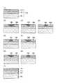
実施の形態1として、感熱材料層と基板との間に位置する記録補助層を有する記録原盤を用いて、光情報記録媒体の原盤を製造する方法を図1〜図4を参照して説明する。図1(A)は、記録原盤の一例の断面を示す。図1(A)に示す記録原盤104において、基板101は、ガラス、シリコン、または樹脂等から成る。この基板101上に、例えば、誘電体または樹脂等から成る記録補助層102を、例えば、スパッタ法やスピンコート法などにより形成する。この記録補助層102の上に、記録補助層102と接するように、感熱材料層103を形成する。感熱材料層103は、露光による昇温により状態変化する材料から成り、例えば、スパッタ法やスピンコート法等により形成される。図示した記録原盤は、実施の形態1の製造方法を実施するのに最小限必要とされる構成に相当する。したがって、記録原盤は、記録補助層が感熱材料層よりも下に位置し、かつ記録補助層により状態変化した部分の断面形状を制御し得る限りにおいて、例えば、記録補助層と感熱材料層との間に位置する界面層(例えば、厚さ1nm未満の薄い層)、または反射層等、図示していない構成要素を含んでもよい。金属反射層107を含む記録原盤104の一例を図1(I)に示す。(Embodiment 1)
As a first embodiment, a method of manufacturing an optical information recording medium master using a recording master having a recording auxiliary layer positioned between a heat-sensitive material layer and a substrate will be described with reference to FIGS. . FIG. 1A shows a cross section of an example of a recording master. In the
図1(B)〜(H)は、記録原盤に光を照射することによって、感熱材料層103に昇温により状態変化した部分105が形成された記録原盤を示す。ここでは、状態変化していない部分を符号106で示す。ここで、記録原盤104への記録方法について図2を用いて説明する。記録原盤201は、回転台202に載せられて、回転台202とともに回転させられる。光源203から発せられた記録光206は、レンズ204によって記録原盤201表面に集光される。必要であれば、記録光206は光源203内で変調および/または偏向されていてもよい。記録中、記録ヘッド205と回転台202とは相対的に平行移動し、記録原盤上にスパイラル状に状態変化した部分が順次形成されるように記録が行われる。記録光206としては、レーザ光または電子線束等を用いることができる。図2に示すような装置を用いる、この原盤記録方法は、従来から採用されているものであって、それ自体新規なものではないから詳細な説明は省略する。また、ここで説明した以外の原盤記録方法であっても、感熱材料層103が昇温により状態変化することを利用して所望のパターンを記録する方法であれば、いずれの方法を用いてもよい。 FIGS. 1B to 1H show a recording master in which a
図1(B)〜(D)は、記録補助層102の厚さを一定として、熱伝導率が異なる材料を用いて記録補助層102を形成した場合の、感熱材料層103の状態変化した部分105の断面形状を模式的に示している。記録補助層102を構成する材料の熱伝導率は、図1(B)>図1(C)>図1(D)の順で高い。図1(B)〜(D)より、記録補助層102を構成する材料の熱伝導率によって、状態変化した部分105の断面形状が変化することがわかる。記録補助層が感熱材料層と基板との間に位置する記録原盤において、記録補助層を構成する材料の熱伝導率だけを変化させると、熱伝導率が小さいほど、感熱材料層の基板側表面から放出される熱量がより小さくなる。即ち、記録補助層の熱伝導率が小さいほど、感熱材料層の表面からより深い部分が昇温することが可能となるので、図1(D)に示すように、状態変化した部分と状態変化していない部分との境界がより急な傾きを有することとなる。 FIGS. 1B to 1D show portions where the state of the heat-
図1(E)および(F)は、熱伝導率が基板101を構成する材料よりも小さい材料で記録補助層102を形成したときに、記録補助層102の厚さを変化させることによって、感熱材料層103の状態変化した部分105の断面形状がどのように変わるかを模式的に示している。図1(E)に示す記録原盤は、記録補助層102の厚さがより大きいために、感熱材料層103から熱が放出されることをより抑制し、状態変化した部分と状態変化していない部分との間の境界の傾きがより大きくなる。図1(G)および(H)は、熱伝導率が基板101を構成する材料よりも大きい材料で記録補助層102を形成したときに、記録補助層102の厚さを変化させることによって、状態変化した部分105がどのように変化するかを模式的に示す。記録補助層102の熱伝導率を基板101の熱伝導率よりも大きくすることによって、記録補助層を設けない場合と比較して、状態変化した部分と状態変化していない部分との境界の傾きがより緩やかになる。また、記録補助層102の厚さが大きい程、状態変化した部分と状態変化していない部分との間の境界の傾きがより小さくなる。図1(E)〜(H)に示すように、記録補助層102の厚さを変化させることにによっても、記録時の昇温により状態変化した部分105の分布を変化させ得ることが分かる。なお、図1(B)〜(H)は、記録補助層の熱伝導率および厚さが、感熱材料層の状態変化した部分の断面形状にどのように影響するかという傾向を表す模式図であることに留意されたい。実際に得られる断面形状は基板を構成する材料の熱伝導率の具体的な数値、この数値と記録補助層を構成する材料の熱伝導率の具体的な数値との差、記録補助層の実際の厚さ等によって決定される。 FIGS. 1E and 1F show heat sensitivity by changing the thickness of the recording
状態変化した部分105を形成した後に、記録原盤104に第一のエッチングを施す。第一のエッチングは、記録時の昇温により状態変化した部分105と状態変化していない部分106とでエッチングレートが異なる条件にて実施する。第一のエッチングの例としては、反応性イオンエッチングなどのドライエッチング、および酸またはアルカリ等によるウエットエッチング等が挙げられる。尤も、第一のエッチングの具体的な方法はこれらに限定されず、状態変化した部分105と状態変化していない部分106とでエッチングレートが異なる条件にて実施できる方法であれば、いずれの方法を用いてもよい。 After forming the state-changed
図3にエッチング前の記録原盤およびエッチング後に得られる原盤を示す。図3(A)および(B)はエッチング前の記録原盤を示す。図3(C)および(D)は、それぞれ図3(A)および(B)に示す記録原盤を、状態変化した部分105のエッチングレートが状態していない部分106のエッチングレートよりも高くなる条件にてエッチングを実施して得られる原盤を示す。この場合、状態変化した部分105は原盤において、凹部を形成する。この凹部の傾斜角は、それぞれ301で表される角度に相当する。前述のとおり、凹部の傾斜角は、凹部の深さtの2分の1のところにおける凹部の側面の接線kと原盤の主表面に平行な面pとが、エッチング後に残っている部分の側でなす角度をいう。したがって、図3(C)に示すように、凹部が原盤表面に向かって広がっている漏斗形状である場合に、傾斜角は鋭角となる。図3(E)および(F)は、それぞれ図3(A)および(B)に示す記録原盤を、状態変化した部分105のエッチングレートが状態変化していない部分106のエッチングレートよりも低くなる条件にてエッチングを実施して得られる原盤を示す。この場合、状態変化した部分105は、原盤において凸部を形成する。この凸部の傾斜角は、それぞれ302で表される角度に相当する。前述のとおり、凸部の傾斜角は、凸部の高さhの2分の1のところにおける凸部の側面の接線jと原盤の主表面に平行な面pとが、エッチング後に残っている部分の側でなす角度をいう。したがって、図3(F)に示すように、凸部が下側に向かって面積が広くなっている円錐形状である場合に、傾斜角は鋭角となる。図3に示すように、エッチングによって、状態変化した部分105が、そのままの形状で凹または凸として形成された原盤を作成することができる。 FIG. 3 shows a recording master before etching and a master obtained after etching. 3A and 3B show a recording master before etching. 3 (C) and 3 (D) show the condition that the recording master shown in FIGS. 3 (A) and 3 (B) is higher than the etching rate of the
第一のエッチングは、記録補助層102のエッチングレートが状態変化した部分105と状態変化していない部分106のうちエッチングレートの高い方よりも低くなる条件にて実施されることが好ましい。即ち、図3(C)および(D)のように、状態変化した部分をエッチングにより凹部とする場合には、記録補助層のエッチングレートは状態変化した部分のエッチングレートよりも低いことが好ましい。図3(E)および(F)のように、状態変化した部分を凸部とする場合には、記録補助層のエッチングレートは、状態変化していない部分のエッチングレートよりも低いことが好ましい。記録補助層のエッチングレートが低いことが望ましい理由は、第一に、エッチングにより形成される凹凸パターンにおいて凹部の底面(一般に、記録補助層の露出表面となる)がより平坦になることである。凹部の底面が平坦であると、この原盤またはこの原盤を転写して得たスタンパから製造される光情報記録媒体において、凹凸パターンを光学的に再生する際にノイズ成分の小さい信号を得られる。第二に、第一のエッチングの際に、記録補助層102のエッチングされる量が少ないほど、記録時に潜像として作成されるパターンに、より忠実な凹凸パターンをエッチングにより形成することができることである。そのことは、本発明に基づいて凹凸パターンの断面形状をより効果的に制御することを可能にする。したがって、第一のエッチングにおいて、記録補助層のエッチングレートは、状態変化した部分および状態変化していない部分のエッチングレートのいずれよりも低い(即ち、最も低い)ことが好ましく、ゼロであってもよい。実施の形態1として示す図3は、記録補助層102のエッチングレートが実質的にゼロである例を示しているが、本発明は、第一のエッチングの際の記録補助層102のエッチングレートが0よりも大きい形態をも含むことに留意すべきである。 The first etching is preferably performed under the condition that the etching rate of the recording
以上において説明したように、本発明の方法は、記録補助層の熱伝導率および厚みを選択することにより、最終的に原盤に形成される凹凸パターンの断面形状を制御することを可能にする。断面形状を表すパラメータとして、上述した傾斜角を用いることができる。記録により形成したパターン(単に「記録パターン」と呼ぶことがある)が凹として形成される場合も、凸として形成される場合も、傾斜角が90度であると、より微細な記録パターンをより安定に形成しやすく、また、原盤から製造される光情報記録媒体の信号特性を良好なものとすることができる。原盤からスタンパをさらに作成する場合には、傾斜角は0度よりも大きいことを条件として90度よりも小さいことが好ましく、50度〜73度であることがより好ましい。傾斜角が90度未満であると、原盤からスタンパへの凹凸パターンの転写およびスタンパから樹脂基板への凹凸パターンの転写が容易となるという利点がある。但し、ここで挙げた数値範囲は一般的なものであって、傾斜角の最適な値は、原盤を用いて行われるその後の工程、および最終的に作成される光情報記録媒体の使用法により異なることに留意されたい。所望の傾斜角がいずれの値であっても、本発明の方法を用いれば、材料の選択肢の少ない感熱材料を変えることなく、記録補助層によって、容易に傾斜角を制御することが可能になる。また、従来のヒートモードによる原盤記録に比べて、より大きな傾斜角の凹部または凸部を得ることが可能となる。 As described above, the method of the present invention makes it possible to control the cross-sectional shape of the concavo-convex pattern finally formed on the master by selecting the thermal conductivity and thickness of the recording auxiliary layer. The inclination angle described above can be used as a parameter representing the cross-sectional shape. Whether the pattern formed by recording (which may be simply referred to as “recording pattern”) is formed as a concave or a convex, if the inclination angle is 90 degrees, a finer recording pattern can be obtained. It is easy to form stably, and the signal characteristics of the optical information recording medium manufactured from the master can be made good. When the stamper is further created from the master, the inclination angle is preferably smaller than 90 degrees on condition that it is larger than 0 degrees, and more preferably 50 degrees to 73 degrees. When the inclination angle is less than 90 degrees, there is an advantage that the uneven pattern transfer from the master to the stamper and the uneven pattern transfer from the stamper to the resin substrate are facilitated. However, the numerical range given here is general, and the optimum value of the inclination angle depends on the subsequent process performed using the master and the usage of the optical information recording medium finally created. Note that it is different. Regardless of the desired inclination angle, if the method of the present invention is used, the inclination angle can be easily controlled by the recording auxiliary layer without changing a heat-sensitive material with few material options. . In addition, it is possible to obtain a concave portion or a convex portion having a larger inclination angle as compared with the master recording in the conventional heat mode.
実施の形態1はまた、感熱材料層103の記録感度を向上させて、様々な原盤構成を実現することを可能にする。例えば、記録補助層102の熱伝導率が基板101のそれよりも小さい場合には、記録補助層102を設けることにより、状態変化した部分105の断面形状を変化させ得るだけでなく、記録時の感度を向上させることもできる。より具体的にいえば、記録補助層を感熱材料層の下側に好ましくは隣接させるように設けることによって、感熱材料層の露光に使用される波長の光の吸収率を高くする作用をする層を感熱材料層の下方に配置することが可能となる。例えば、基板101をシリコン基板とすることによって、そのような光学的効果を得ることができる。シリコン基板は、熱伝導率が一般的なガラスや樹脂に比べて2桁も高いために、感熱材料層とシリコン基板とが接する原盤にヒートモード記録を実施することは困難である。本発明の方法において、記録補助層を熱伝導率の小さい材料で形成すれば、このシリコン基板で記録原盤を作製することを可能にする。シリコン基板はまた、清浄であるという点からも好ましく用いられる。シリコン基板以外の熱伝導率の高い基板を必要に応じて用いることもまた可能である。あるいはまた、感熱材料層の記録感度を向上させるために、図1(I)に示すように、基板101と記録補助層102との間に、Au、Ag、Al、Cu、Pt、Pd、Cr、Ni等の金属元素から選択される1以上の元素もしくはそれらの混合物または化合物などから成る、熱伝導率の非常に大きい金属反射層107を設けることも容易となる。 The first embodiment also improves the recording sensitivity of the heat-
また、感熱材料層103の光吸収率を増大させることは、記録補助層102を構成する材料の光学定数および記録補助層102の厚さを適切に選択することによっても可能である。光学定数は、例えば、記録に用いる光の波長における記録補助層102を構成する材料の屈折率を適宜調節することによって適切に選択される。記録補助層の適切な光学定数は、基板101、記録補助層102、および感熱材料層103の間の光学的な効果(例えば、反射および干渉効果)を考慮して決定される。また、記録原盤を構成する各層の光学的な効果を考慮して、各層の光学定数の組み合わせが適切となるように記録原盤を構成することによって、感熱材料層103の光吸収率を深さ方向で制御することもでき、それにより原盤上に形成される凹凸パターンの断面形状を制御することもできる。 Further, it is possible to increase the light absorption rate of the heat-
本発明の方法に従って、原盤上に形成される凹凸パターンの断面形状を制御する具体例を図4を参照して説明する。図4(A)および(B)は、それぞれ、露光前の記録原盤を示す。ここでは、基板401として、ソーダガラス基板を用いた例を説明する。ソーダガラス以外の基板401材料としては、例えば、石英ガラス、シリコン、ポリカーボネート樹脂、アクリル樹脂、およびオレフィン樹脂等がある。基板401の材料としては、平板を形成できる材料であればいずれの材料も用いることができる。ここで、基板401の厚さは、6.0mmである。基板401の厚さは、これに限定されず、例えば0.4〜10.0mmの範囲内から選択される。基板の光学定数によって、記録補助層403によりもたらされる光学的な効果は変化するため、それを考慮して記録補助層の厚さを下記に示す値から変更することが好ましい場合もある。 A specific example of controlling the cross-sectional shape of the concavo-convex pattern formed on the master according to the method of the present invention will be described with reference to FIG. FIGS. 4A and 4B each show a recording master before exposure. Here, an example in which a soda glass substrate is used as the
感熱材料層402は、スパッタ法により、TeO1.0Pd3.0で表される材料で形成した。また、その厚さは45nmとした。Teの代わりに、Sb、Se、Sn、Ge、Mo、WまたはTi等を用いることもできる。また、Pdに代えて、他の金属元素、例えば、Au、Ag、CuまたはPd等の貴金属を用いてよい。これらの貴金属を含む材料で感熱材料層を形成することにより、エッチングの際の残膜率(状態変化した部分が凹部となる場合には、未露光部(即ち、状態変化していない部分)のエッチング前の厚さに対するエッチング後の厚さの割合)を上げることができる。感熱材料層402を構成するのに適した材料は、一般式、M1XOM2Y(式中、M1は、Te、Sb、Se、Sn、Ge、Mo、WおよびTiから選択される1または複数の金属であり、M2は、M1以外の金属元素であり、好ましくはAu、Ag、CuおよびPdから選択される1または複数の元素であり、0.3<X<1.7、0.05<Y<0.52である)で表される。尤も、感熱材料層402を構成する材料は、この式で表されない材料であってもよい。また、感熱材料層402の厚さも、原盤に形成すべき凹凸パターンに応じて変化させることができる。The heat
図4(A)に示す記録原盤において、記録補助層403aは、スパッタ法により形成された、ZnSとSiO2とをモル比で4:1の割合で含む層であり、その厚さは45nmである。図4(B)に示す記録原盤において、記録補助層403bは、スパッタ法により形成されたSiO2から成る層であり、その厚さは45nmである。記録補助層403aおよび403bの厚さは、45nmに限定されるわけではなく、感熱材料層402の記録波長での光吸収率が最大となるように感熱材料層402の材料および厚さに応じて選択することが記録感度を高めるためには好ましい。例えば、感熱材料層402aを材料を変化させずに、厚さが60nmなるように形成した場合には、記録補助層403aの厚さが35nmのときに記録感度が最大となった。In the recording master shown in FIG. 4A, the
これらの2つの記録原盤に、波長405nmのレーザ光とNA0.9の対物レンズとを用いてピット列および案内溝に対応するパターンが状態変化した部分として形成されるように露光した。次いで、1.7%のTMAH(水酸化テトラメチルアンモニウム)によるウエットエッチングを60秒間行った。その結果、図4(A)および(B)に示す記録原盤から、それぞれ図4(C)および(D)に示す原盤が得られた。ここで使用したエッチング液は一例であり、TMAHの濃度は、例えば、1.0%〜2.4%の範囲から選択することができる。あるいは、TMAHの代わりに、例えば、KOHおよびNaOH等の他のアルカリ水溶液を用いても同様にエッチングを実施できる。エッチングによって、状態変化した部分が凹となり、原盤上に直径90nmの円形ピットや幅70nmの案内溝が安定に形成された。このような凹部の形成は、一層当たり25GB以上の記録容量を持つ直径12cmの光情報記録媒体を製造するのに十分な解像度が達成されたことを意味する。 These two recording masters were exposed using a laser beam with a wavelength of 405 nm and an objective lens with NA of 0.9 so that the pattern corresponding to the pit row and the guide groove was formed as a state-changed portion. Next, wet etching with 1.7% TMAH (tetramethylammonium hydroxide) was performed for 60 seconds. As a result, the masters shown in FIGS. 4C and 4D were obtained from the recording masters shown in FIGS. 4A and 4B, respectively. The etching solution used here is an example, and the concentration of TMAH can be selected from a range of 1.0% to 2.4%, for example. Alternatively, instead of TMAH, for example, other alkaline aqueous solutions such as KOH and NaOH can also be used for etching. As a result of the etching, the changed state became concave, and a circular pit with a diameter of 90 nm and a guide groove with a width of 70 nm were stably formed on the master. The formation of such recesses means that a resolution sufficient to manufacture an optical information recording medium having a diameter of 12 cm and a recording capacity of 25 GB or more per layer has been achieved.
原盤上に形成された凹部の傾斜角404は、図4(C)に示す原盤においては73度、図4(D)に示す原盤においては28度であった。また、記録時の感度は、図4(A)に示す記録原盤の場合が、図4(B)に示すものよりも高く、前者は後者の約2倍となった。これらのことから、本発明の方法に従って記録補助層403を形成した記録原盤を使用し、さらに、例えば記録補助層の材料の組成比を変えることによって、原盤に形成される凹部の断面形状の傾斜角404を例えば28度から73度の任意の値に制御すること、ならびに記録感度を例えば約2倍の幅で制御することが可能であることが分かる。さらに、本発明の方法によれば、従来の方法に従って、石英ガラスまたはソーダガラスから成る基板に感熱材料層のみを配置した記録原盤を用いてヒートモード記録した原盤において実現することが困難であった、50度以上の高い傾斜角を実現できることも分かる。 The
ここでは、ZnSとSiO2の組成比を変えて記録補助層を形成した例を用いて本発明の方法を説明した。記録補助層を構成する材料は、これらに限定されない。記録補助層は、例えば、ZnSe等のセレン化物、Si−O、Ge−O、Al−O、Zn−O、Y−O、La−O、Ti−O、Zr−O、Hf−O、Nb−O、Ta−O、Cr−O、Mo−O、W−O、Sn−O、In−O、Sb−O、およびBi−O等の酸化物、Si−N、Ge−N、Al−N、Zn−N、Ti−N、Zr−N、Hf−N、Nb−N、Ta−N、Cr−N、Mo−N、W−N、Sn−N、およびIn−N等の窒化物、Si−O−N、Ge−O−N、Al−O−N、Ti−O−N、Zr−O−N、Hf−O−N、Nb−O−N、Ta−O−N、Cr−O−N、Mo−O−N、W−O−N、Sn−O−N、およびIn−O−N等の窒酸化物、Ge−C、Cr−C、Si−C、Al−C、Ti−C、Zr−C、およびTa−C等の炭化物、Si−F、Al−F、Mg−F、Ca−F、およびLaF等の弗化物、ならびに先に例示したZnSおよびSiO2で構成される群から選択される一または複数の材料、またはそれらの混合材料を、スパッタ法や蒸着法を用いて成膜することによって、形成してよい。Here, the method of the present invention has been described using an example in which the recording auxiliary layer is formed by changing the composition ratio of ZnS and SiO2 . The material constituting the recording auxiliary layer is not limited to these. The recording auxiliary layer includes, for example, selenide such as ZnSe, Si—O, Ge—O, Al—O, Zn—O, Y—O, La—O, Ti—O, Zr—O, Hf—O, Nb. -O, Ta-O, Cr-O, Mo-O, W-O, Sn-O, In-O, Sb-O, Bi-O and other oxides, Si-N, Ge-N, Al- N, Zn—N, Ti—N, Zr—N, Hf—N, Nb—N, Ta—N, Cr—N, Mo—N, W—N, Sn—N, and nitrides such as In—N , Si—O—N, Ge—O—N, Al—O—N, Ti—O—N, Zr—O—N, Hf—O—N, Nb—O—N, Ta—O—N, Cr Nitrogen oxides such as —O—N, Mo—O—N, W—O—N, Sn—O—N, and In—O—N, Ge—C, Cr—C, Si—C, Al—C Ti-C, Zr-C, Ta-C, etc. Carbide, Si-F, Al-F , Mg-F, Ca-F, and fluorides such as LaF, and one or more materials selected from the group consisting of ZnS and SiO2 exemplified above or, You may form those mixed materials by forming into a film using a sputtering method or a vapor deposition method.
あるいは、記録補助層は、有機材料で形成してよく、例えば、アクリル樹脂、エポキシ樹脂、またはそれらの混合物から成る層であってよい。樹脂材料から成る記録補助層は、例えば、スピンコート法により成膜する方法で形成される。さらに、樹脂材料を使用する場合にも、混合比または組成比を選択することによって、記録補助層403の熱伝導率および光学定数を制御して、凹凸パターンの断面形状の制御を実施することができる。勿論、ここで説明した方法以外の方法を用いて、記録補助層の熱伝導率および光学定数の少なくとも一方を適当に選択することで、原盤上に形成される凹凸パターンの断面形状(具体的には傾斜角)を制御することは可能である。 Alternatively, the recording auxiliary layer may be formed of an organic material, for example, a layer made of an acrylic resin, an epoxy resin, or a mixture thereof. The recording auxiliary layer made of a resin material is formed, for example, by a method of forming a film by spin coating. Furthermore, even when a resin material is used, it is possible to control the cross-sectional shape of the concavo-convex pattern by controlling the thermal conductivity and optical constant of the recording auxiliary layer 403 by selecting the mixing ratio or composition ratio. it can. Of course, by using a method other than the method described here and appropriately selecting at least one of the thermal conductivity and the optical constant of the recording auxiliary layer, the cross-sectional shape of the concavo-convex pattern formed on the master (specifically, It is possible to control the inclination angle.
(実施の形態2)
実施の形態2として、感熱材料層の上側表面(基板から遠い側の表面)に記録補助層を有する記録原盤を用いて、原盤を製造する方法を図5を参照して説明する。図5(A)は、記録原盤の一例を示す。この記録原盤504は、基板501上に感熱材料層502を形成し、さらに感熱材料層502上に、記録補助層503を形成することにより形成される。図5(A)において、506は外部媒質(即ち、露光の際の雰囲気)を指し、これは一般には空気である。記録原盤504を構成する基板501の材料および感熱材料層502の材料および形成方法については、実施の形態1に関連して説明したとおりである。記録補助層503は、実施の形態1に関連して説明した材料および方法により形成される膜であってよい。あるいは、記録補助層503は液体であってもよい。具体的には、露光を、記録補助層503となる液体を配置した(例えば塗布した)状態、または当該液体に記録原盤を浸漬した状態にて実施することによっても、この実施の形態2を実施することができる。図示した記録原盤は、実施の形態2の製造方法を実施するのに最小限必要とされる構成に相当する。したがって、記録原盤は、感熱材料層が記録補助層と基板との間に位置する構成を有する限りにおいて、例えば、前述のような界面層または反射層等、図示していない構成要素を含んでもよい。(Embodiment 2)
As Embodiment 2, a method of manufacturing a master using a recording master having a recording auxiliary layer on the upper surface (surface far from the substrate) of the heat-sensitive material layer will be described with reference to FIG. FIG. 5A shows an example of a recording master. The
図5(B)〜(H)は、記録原盤に光を照射することによって、感熱材料層502に昇温により状態変化した部分505と状態変化していない部分507とが形成された記録原盤を示す。記録原盤への記録方法は第1の実施の形態に関連して説明したとおりであるから省略する。図5(B)〜(D)は、記録補助層503の厚さを一定として、熱伝導率が異なる材料を用いて記録補助層を形成した場合の、感熱材料層502の状態変化した部分505の断面形状を模式的に示している。記録補助層503を構成する材料の熱伝導率は、図5(B)>図5(C)>図5(D)の順で高い。図5(B)〜(D)より、記録補助層503を構成する材料の熱伝導率によって、状態変化した部分505の断面形状が変化することがわかる。記録補助層が感熱材料層の上に位置する記録原盤において、記録補助層を構成する材料の熱伝導率だけを変化させると、熱伝導率が小さいほど、感熱材料層の表面付近に熱が溜まりやすくなる。即ち、記録補助層の熱伝導率が小さいほど、感熱材料層の表面から深い部分で昇温しにくくなるので、図5(D)に示すように、状態変化した部分と状態変化していない部分との境界がより緩やかな傾きを有することとなる。 5B to 5H show a recording master in which a
図5(E)および(F)は、記録補助層503を熱伝導率が外部媒質506の熱伝導率よりも小さい材料で形成したときに、記録補助層503の厚さを変化させることによって、感熱材料層502の状態変化した部分505の断面形状がどのように変わるかを模式的に示している。図5(E)に示す記録原盤は、記録補助層503の厚さがより大きいために、感熱材料層502の表面から熱が放出されることをより抑制し、状態変化した部分と状態変化していない部分との間の境界の傾きがより小さくなる。図5(G)および(H)は、熱伝導率が外部媒質506よりも大きい材料で記録補助層503を形成したときに、記録補助層503の厚さを変化させることによって、状態変化した部分505の断面形状がどのように変化するかを模式的に示す。記録補助層503の熱伝導率を外部媒質506の熱伝導率よりも大きくすることによって、記録補助層を設けない場合と比較して、状態変化した部分と状態変化していない部分との傾きがより大きくなる。また、記録補助層503の厚さが大きいほど、状態変化した部分と状態変化していない部分との間の境界の傾きはより大きくなる。一般に感熱材料層502が曝されている外部媒質506は固体や液体に比べて非常に熱伝導率の低い空気である。その場合、記録補助層503の熱伝導率を外部媒質よりも小さくすることは一般に困難であるから、状態変化した部分の断面形状の制御は、図5(G)および(H)に示すように実現される。ただし、LIL(液浸レンズ法)による原盤記録等のように外部媒質506として液体を用いる場合には、状態変化した部分505の制御は、図5(E)〜(H)のいずれに示すようにも実現可能である。このように、記録補助層を感熱材料層の上に設ける場合にも、記録補助層503の厚さを変化させることによっても、記録時の昇温により状態変化した部分505の分布を変化させ得ることが分かる。なお、なお、図5(B)〜(H)は、記録補助層の熱伝導率および厚さが、感熱材料層の状態変化した部分の断面形状にどのように影響するかという傾向を表す模式図であることに留意されたい。実際に得られる断面形状は外部媒質の熱伝導率の具体的な数値、この数値と記録補助層を構成する材料の熱伝導率の具体的な数値との差、記録補助層の実際の厚さ等によって決定される。 FIGS. 5E and 5F show that the thickness of the recording
次に、記録後の記録原盤504から記録補助層503を除去する処理を行う。記録補助層503の除去は、好ましくは感熱材料層502に及ぼす影響が小さくなるように実施される。記録補助層503の主成分が、例えば、ノボラック樹脂、アクリル樹脂、またはポリカーボネート樹脂等の有機物であり、感熱材料層502の主成分が、例えば、Te、Sb、Se、Sn、GeまたはMo等の化合物のような無機材料である場合には、例えば、有機溶剤によるウエットエッチングまたは、酸素もしくは希ガス等を使ったプラズマエッチングが好ましく実施される。これらのエッチングを用いれば、記録補助層503のエッチングレートの方が感熱材料層502のエッチングレートよりも十分大きくなり、効率的に記録補助層503のみを除去することが可能である。また、感熱材料層502を構成する材料が水溶性でない場合には、記録補助層503を、例えば、ポリビニルアルコール、ポリエチレンオキサイド、またはポリアクリル酸ナトリウム等の水溶性の材料で形成すると、容易に記録補助層503のみを除去することが可能となる。また、感熱材料層502を構成する材料がアルカリ可溶でなければ、記録補助層503を、例えば、ノボラック樹脂またはアクリル樹脂等のアルカリ可溶の材料で形成すると、容易に記録補助層503のみを除去することが可能となる。また、感熱材料層502を構成する材料が酸可溶でなければ、記録補助層503を酸可溶の材料で形成すると、容易に記録補助層503のみを除去することが可能となる。 Next, the recording
次に、記録時の昇温により状態変化した部分505と状態変化していない部分507とでエッチングレートの異なる条件にて、第一のエッチングを実施する。第一のエッチングの例は、先に実施の形態1に関連して説明したとおりであるから、ここでは省略する。また、この実施の形態2においても、第一のエッチングは、基板501のエッチングレートが、状態変化した部分505と状態変化していない部分507のうちエッチングレートの高い方よりも低くなる条件にて実施することが好ましい。その理由については、実施の形態1において、説明したとおりであるからここでは省略する。この第一のエッチングにより、記録時の昇温により状態変化した領域505が凸または凹として原盤上に形成される。 Next, the first etching is performed under conditions where the etching rate is different between the
以上においては、記録補助層503の除去と感熱材料層502のエッチングを別工程として実施する形態を説明した。別法として、記録補助層503の除去と感熱材料層502のエッチングを同時に行うこともできる。その場合、工程数が減ることによって、汚染の可能性およびコストを低減することができる。具体的には、例えば、感熱材料層502がTeまたはSbの化合物等から成り、記録時の昇温により状態変化した部分505と状態していない部分507とでアルカリエッチングの際のエッチングレートが大きく異なる層であり、記録補助層503が、例えば、ノボラック樹脂またはアクリル樹脂等のアルカリ可溶の材料から成る場合には、アルカリエッチングによって、記録補助層503の除去と感熱材料層502のエッチングを同時に実施できる。また、感熱材料層502のエッチングを酸を用いて実施する場合には、記録補助層503を酸可溶の材料で形成すればよい。感熱材料層502のエッチングを水溶液を用いて実施する場合には、記録補助層503を、例えば、ポリビニルアルコール、ポリエチレンオキサイド、またはポリアクリル酸ナトリウム等の水溶性の材料で形成すれば、1回の処理で感熱材料層502のエッチングと記録補助層503の除去を実施できる。他にも様々な方法がある。いずれの方法を採用する場合も、エッチングを、記録補助層503のエッチングレートが感熱材料層502のエッチングレートより大きくなるように実施することによって、効率的に記録補助層503を除去できる。また、記録補助層503の除去と感熱材料層502のエッチングを同時に実施する場合には、記録補助層503のエッチングレートは、状態変化した部分505と状態変化していない部分507のエッチングレートのうち低い方よりも高いことが好ましい。それにより、エッチング後に感熱材料層において残る部分(即ち、状態変化した部分505と状態変化していない部分507のエッチングレートのうち低い方)の表面荒れの程度を低くできる。 In the above, the embodiment in which the removal of the recording
このように、実施の形態2で説明した本発明の方法を用いれば、感熱材料層の材料を変更することなく、容易に、原盤上の凹凸パターンの断面形状を制御することが可能となる。 As described above, if the method of the present invention described in Embodiment 2 is used, the cross-sectional shape of the uneven pattern on the master can be easily controlled without changing the material of the heat-sensitive material layer.
(実施の形態3)
実施の形態3として、2つの記録補助層を感熱材料層を挟むように配置した記録原盤を用いて、光情報記録媒体の原盤を製造する方法を図6を参照して説明する。図6(A)は、記録原盤の一例を示す。記録原盤605は、基板601上に、第一の記録補助層602を形成し、第一の記録補助層602上に感熱材料層603を形成し、感熱材料層603上に第二の記録補助層604を形成することにより得られる。記録原盤605を構成する基板601の材料および感熱材料層603の材料および形成方法は、実施の形態1に関連して説明したとおりである。また、第一の記録補助層602および第二の記録補助層604も、実施の形態1に関連して説明した材料および方法により形成される。第二の記録補助層604は、実施の形態2に関連して説明したように液体であってもよく、その場合は、記録の際に液体を塗布または浸漬により供給する必要がある。図示した記録原盤は、実施の形態3の製造方法を実施するのに最小限必要とされる構成に相当する。したがって、記録原盤は、感熱材料層が2つの記録補助層で挟まれるように構成されている限りにおいて、例えば、記録補助層と感熱材料層との間に位置する界面層、または反射層等、図示していない構成要素を含んでもよい。(Embodiment 3)
As Embodiment 3, a method of manufacturing an optical information recording medium master using a recording master in which two recording auxiliary layers are arranged so as to sandwich a thermosensitive material layer will be described with reference to FIG. FIG. 6A shows an example of a recording master. The
例えば、図6(B)に示すように、基板601と第一の記録補助層602との間に、金属反射層606を設けてよい。金属反射層606の材料および形成方法は、実施の形態1に関連して説明したとおりである。また、この形態においても、実施の形態1に関連して説明したように、第一の記録補助層602の存在により、金属反射層606による熱的な悪影響を小さくして、光学的な効果を得ることが可能となる。 For example, as shown in FIG. 6B, a metal
図6(A)および(B)に示す記録原盤605および605aには、所望のパターンが記録される。その方法は、実施の形態1と同じである。次いで、第二の記録補助層604を除去し、さらに第一のエッチングを実施して、凹凸パターンが形成された原盤を得る。あるいは、第二の記録補助層604の除去と第一のエッチングを同時に実施してもよい。いずれの方法も先に実施の形態3に関連して説明したとおりであるから、ここでは省略する。 A desired pattern is recorded on the
記録原盤605において、第一の記録補助層602は実施の形態1で説明した記録補助層102と同じように機能させることができ、第二の記録補助層604は実施の形態2で説明した記録補助層503と同じように機能させることができる。したがって、記録原盤605を用いることによって、実施の形態1および実施の形態2によりもたらされる利点を同時に得ることができ、記録補助層を1つだけを形成した記録原盤を用いる場合と比較して、原盤上の凹凸パターンの断面形状および記録時の感度をより自在に制御することができる。 In the
(実施の形態4)
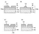
実施の形態4として、感熱材料層に凹凸を形成する第一のエッチングの後、さらに第二のエッチングを実施する方法を、図7を参照して説明する。実施の形態4では、実施の形態1または実施の形態3で使用される記録原盤を用いて、それぞれ、実施の形態1または実施の形態3と同様の方法で感熱材料層に凹凸パターンを形成する。図7(A)に、感熱材料層701の記録時の昇温により状態変化した部分が凹部として形成された記録原盤704aを、図7(B)に、感熱材料層701の記録時に昇温した部分が凸部として形成された記録原盤704bを、それぞれ断面図で示す。いずれの記録原盤においても、感熱材料層701は記録補助層702上に形成されている。記録補助層702の下側表面に隣接している層703は、実施の形態1および実施の形態3に関連して説明したように、一般的には基板または金属反射層であるが、これらに限定されない。以下、図7(A)に示す状態変化した部分が凹として形成される記録パターンが形成された記録原盤を用いて実施の形態4を説明する。(Embodiment 4)
As Embodiment 4, a method of performing second etching after the first etching for forming irregularities in the heat-sensitive material layer will be described with reference to FIG. In the fourth embodiment, using the recording master used in the first or third embodiment, a concavo-convex pattern is formed on the heat-sensitive material layer by the same method as in the first or third embodiment, respectively. . FIG. 7A shows a
実施の形態4においては、第一のエッチングを実施した後の記録原盤に、感熱材料層701をマスクとした第二のエッチングを行う。第二のエッチングにおいては、第一のエッチング後に残った感熱材料層701の部分がマスクとして作用し、第一のエッチング後に露出している記録補助層702の部分を除去して凹部を形成する。第二のエッチングは、反応性イオンエッチング、プラズマエッチング、または酸もしくはアルカリ等によるウエットエッチング等であってよい。感熱材料層701を、例えば、Te、Sb、Se、Sn、GeまたはMo等の化合物である無機材料で形成し、記録補助層702を、例えば、ノボラック樹脂、アクリル樹脂、またはポリカーボネート樹脂等の有機物で形成する場合には、第二のエッチングは、プラズマエッチング、または有機溶剤によるウエットエッチングであることが、実施が容易であることから、好ましい。あるいは、記録補助層702をSiO2で形成し、フッ素系のガスまたは液体でSiO2を選択的に除去する方法によって第二のエッチングを実施することも好ましい。In the fourth embodiment, the second etching using the heat-
図7(C)に第二のエッチング後の記録原盤を示す。図7(C)において、d1は記録補助層702をエッチングする深さに相当する。第二のエッチングは、マスクが消失することを防止するように実施することが好ましい。マスクが消失すると、記録補助層702のマスクされるべき部分がエッチングされて所望の凹凸パターンを形成できなくなるという不都合がある。したがって、第二のエッチングは、第二のエッチング前の感熱材料層701の平均的な厚みをd2(図7(A)参照)としたときに、感熱材料層701に対する記録補助層702のエッチング選択比を(d1/d2)以上となるように実施することが好ましい。図7(B)に示すような記録原盤を第二のエッチングに付すと、凸部がマスクとなって、記録補助層702に凹部が形成されることとなる(図示せず)。 FIG. 7C shows the recording master after the second etching. In FIG. 7C, d1 corresponds to the depth at which the
また、図7(D)に示すように、下層703の表面が露出するまで第二のエッチングを行う場合は、さらに、下層703に対する記録補助層702のエッチング選択比が1より大きいことが好ましい。そのようにエッチング選択比を選択することで、第二のエッチングにより露出される下層703の表面が、第二のエッチングにより荒らされる程度を小さくし得るため、凹部の底が平滑である良好なパターンが得られる。例えば、記録補助層702がSiO2を含み、下層703がSiから成る場合には、例えばフルオロカーボン等のフッ素系材料による反応性イオンエッチングを第二のエッチングとして実施することによって下層703が露出する場合でも第二のエッチングによる表面の荒れを少なくし得る。記録補助層702が、例えば、ノボラック樹脂、アクリル樹脂またはポリカーボネート樹脂等の有機物から成り、下層703がガラスまたはシリコン等の無機材料から成る場合には、プラズマエッチング、または有機溶剤によるウエットエッチングを第二のエッチングとして実施することが、下層703を露出させる場合にも好ましい。また、下層703が、上述の金属反射層である場合には、下層703に対する記録補助層702のエッチング選択比を大きくしやすい。したがって、下層703を金属反射層とする構成の記録原盤は、実施の形態4において好ましく用いられる。Further, as shown in FIG. 7D, when the second etching is performed until the surface of the
次に、第三のエッチングを実施して、マスクとして用いた感熱材料層701を除去して、原盤を得る。第三のエッチングの例としては、反応性イオンエッチングおよびプラズマエッチング等のドライエッチング、ならびに酸またはアルカリ等によるウエットエッチング等が挙げられる。第三のエッチングは、好ましくは、記録補助層702に対する感熱材料層701のエッチング選択比が1よりも大きくなるように実施することが好ましい。そのようにエッチング選択比を選択することによって、第三のエッチングにより記録補助層702がエッチングされる度合いを低くし得るため、原盤上に良好なパターンが形成される。第二のエッチングにより下層703が露出している場合、もしくは第三のエッチングにより下層703が露出する場合には、第三のエッチングは、下層703に対する感熱材料層701のエッチング選択比も1より大きくなるように実施することがさらに好ましい。第三のエッチングにより下層703がエッチングされる程度を低くして、原盤上に良好なパターンを形成するためである。一例を挙げると、感熱材料層701がTeの酸化物から成り、記録補助層702がSiO2から成り、下層703がSiから成る場合、第三のエッチングとして、TMAHまたはKOH等のアルカリによるエッチングを実施すれば、記録補助層702および下層703にほとんどダメージを与えることなくマスクとしての感熱材料層701を除去することができる。Next, a third etching is performed to remove the heat-
実施の形態4の方法によれば、感熱材料層を除去することにより平坦な記録補助層の表面が露出されて、記録補助層に良好な凹凸パターンを形成することができる。したがって、実施の形態4の方法は、実施の形態1または実施の形態3の方法に従って第一のエッチングを実施している間に感熱材料層の表面が荒れたり、スカムが発生するなどして、良好な凹凸パターンが得られない場合に特に有用である。また、実施の形態4の方法は、実施の形態1または実施の形態3の方法で製造した原盤を更に別工程(例えば、メッキなど)に付す際に、感熱材料層の材料が当該別工程で問題を生じさせる場合にも、好ましく用いられる。このように、実施の形態4の方法を用いれば、ヒートモード記録による光情報記録媒体の原盤製造に用いる感熱材料の選択肢をより広くすることが可能となる。 According to the method of the fourth embodiment, the surface of the flat recording auxiliary layer is exposed by removing the heat-sensitive material layer, and a favorable uneven pattern can be formed on the recording auxiliary layer. Therefore, in the method of the fourth embodiment, the surface of the heat-sensitive material layer is roughened or scum is generated while the first etching is performed according to the method of the first or third embodiment. This is particularly useful when a good uneven pattern cannot be obtained. Further, in the method of the fourth embodiment, when the master manufactured by the method of the first or third embodiment is further subjected to another process (for example, plating), the material of the heat-sensitive material layer is the other process. It is also preferably used when causing problems. As described above, by using the method according to the fourth embodiment, it is possible to broaden the choice of heat-sensitive materials used for manufacturing an optical information recording medium master by heat mode recording.
(実施の形態5)
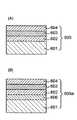
実施の形態5として、感熱材料層の上に光透過層を形成した記録原盤を用いる方法を説明する。図8(A)に、実施の形態5で使用される記録原盤を断面図にて示す。記録原盤805は、基板801上に、記録補助層804を形成し、記録補助層804の上に感熱材料層802を形成し、感熱材料層802上に、光透過層803を形成することにより得られる。記録原盤805を構成する基板801の材料、感熱材料層802および記録補助層804の材料および形成方法は、実施の形態1に関連して説明したとおりである。光透過層803の具体的な材料および形成方法は、後述する。図示した記録原盤804の構成は、実施の形態5の製造方法を実施するのに最小限必要とされる構成の一例である。したがって、記録原盤は、光透過層が最上層として形成されている限りにおいて、例えば、界面層または反射層等、図示していない構成要素を含んでもよい。また、記録補助層804に代えて又はこれとともに、感熱材料層の上に記録補助層が形成されていてもよく、その場合、光透過層は、当該記録補助層の上に形成される。(Embodiment 5)
As a fifth embodiment, a method using a recording master in which a light transmission layer is formed on a heat sensitive material layer will be described. FIG. 8A is a sectional view showing the recording master used in the fifth embodiment. The
光透過層の材料および形成方法を説明する前に、光透過層を形成することの利点を、図9を参照して説明する。図9は、一般的な光情報記録媒体901の構造を示す。図9に示す光情報記録媒体901は、原盤上に形成された凹凸パターンが、直接的に又は間接的に転写されている基板902、基板902上に形成された少なくとも一層の信号層903、および信号層903上に形成された透明な保護層904を有する。信号層903は、例えば、書き換え型および追記型の記録媒体においては、カルコゲン化合物または色素から成る層を含み、必要に応じて記録再生特性を向上させるために、金属またはシリコン等から成る反射層を更に有する。再生専用の光記録媒体においては、基板に形成された凹凸が信号情報となり、信号層903は、この信号情報を反射光の位相差として読み出すために設けられる反射層である。いずれの形態の光情報記録媒体901も、再生および記録はともに、対物レンズ905によって集光される光906(例えばレーザ光)によって行われる。 Before describing the material and forming method of the light transmission layer, advantages of forming the light transmission layer will be described with reference to FIG. FIG. 9 shows the structure of a general optical
光情報記録媒体の記録および再生に使用される対物レンズ905は、DVDおよびCD等の普及に伴い、比較的安価に提供されている。そこで、この対物レンズ905を、原盤を製造する際の露光に使用できれば、原盤製造のコストを低下させることが可能である。しかし、従来の原盤記録方法では、記録光が集光されるべき層が記録原盤表面に配置される、あるいは光情報記録媒体901の保護層904とは光学的に全く異なる層によりカバーされている等の理由のために、球面収差の影響で、光情報記録媒体の再生および記録に使用する対物レンズを、原盤記録に用いることは不可能であった。そのため、原盤記録は、原盤記録専用として製造される非常に高価な対物レンズを必要としていた。 An
本発明の方法は、ヒートモード記録の可能な感熱材料を記録原盤に用いることにより、光情報記録媒体の再生および記録に一般的に用いられる光および対物レンズと実質的に同程度の波長の記録光および対物レンズのNAを用いて原盤記録を実施することを可能にするものである。即ち、本発明の方法は、民生機器で用いられている対物レンズを原盤記録に使用することをより容易にする。しかし、そのような対物レンズを実際に使用することは、前述したように球面収差の影響等により困難である。そこで、本発明者らは、原盤の構成自体を光情報記録媒体と同じものとすることによって、そのようなレンズの使用が可能になると考えた。これが、光透過層803を設ける理由である。即ち、民生機のドライブに搭載される安価な対物レンズを原盤記録の対物レンズとして使用できるようにすることが実施の形態5の方法の利点である。 The method of the present invention uses a heat-sensitive material capable of heat mode recording as a recording master, thereby recording light having substantially the same wavelength as that of light and an objective lens generally used for reproducing and recording optical information recording media. The master recording can be performed using the NA of the light and the objective lens. That is, the method of the present invention makes it easier to use an objective lens used in consumer equipment for master recording. However, it is difficult to actually use such an objective lens due to the influence of spherical aberration as described above. Therefore, the present inventors considered that such a lens can be used by making the configuration of the master itself the same as that of the optical information recording medium. This is the reason why the
したがって、光透過層803は、その光学定数および厚さが光情報記録媒体の保護層904と同程度である層となるように形成される。一般的に、光情報記録媒体の保護層904はポリカーボネート樹脂等の樹脂で形成される。保護層904は、次世代の光情報記録媒体の記録および再生に使用される予定である波長405nm付近において、1.4〜1.6程度の屈折率を有する。したがって、本発明で用いる光透過層803もまた、同程度の波長の光の屈折率がそれに近い材料、例えば、1.35以上1.65以下の材料で形成することが好ましい。具体的には、光透過層803を構成する材料として、例えば、ポリカーボネート樹脂、アクリル樹脂、石英ガラス、およびソーダガラス等が挙げられるが、これらに限定されるものではなく、上記の屈折率を有するいずれの材料でも形成することができる。光透過層803の厚さは、使用する対物レンズに応じて選択される。光透過層803は、その屈折率の制御よりも厚さの制御の方が容易であるため、光透過層803の厚みにより球面収差等の調整を行うとよい。さらに、球面収差の微調整を行いたい場合は、対物レンズと光源との間に、球面収差補正機構を設ければよい。 Therefore, the
光透過層803は、スピンコート法等により、硬化性樹脂を含む液体材料を塗布した後に、溶剤の揮発または紫外線の照射等により硬化性樹脂を硬化させることによって形成してよい。あるいは、光透過層803は、シート状の透明材料を粘着シートまたは接着剤によって接着する方法によって形成してよい。あるいは、光透過層803は、図8(B)〜図8(D)に示す方法で記録原盤に形成してよい。図8(B)は、真空雰囲気807中でシート状の材料を記録原盤表面に被せ、シート状材料を基板801に接着剤806で接合する方法を示す。図8(C)は、袋状のシート材料で記録原盤を包み込み、真空吸引によりシートと記録原盤を密着させた後に封止する方法を示す。図8(D)は、記録原盤を露光するときに、基板および回転台202に形成された開口部808を通じてシート状の透明材料を真空吸着させる方法を示す。光透過層803は、露光の際にその下に位置する層(図8においては感熱材料層であり、感熱材料層の上に記録補助層が形成されている場合には記録補助層)と密着していることを要し、露光の前に、その下に位置する層と接合している必要は必ずしもない。 The
記録原盤への記録方法は実施の形態1に関連して説明したとおりである。記録後、光透過層803を除去する。光透過層803は、光透過層803が、例えば、硬化性樹脂を含む液体材料を硬化させて形成したものである場合には、溶媒を用いて、あるいはプラズマエッチング法等により除去できる。光透過層803が、例えば、シート状の透明材料を粘着シートまたは接着剤によって感熱材料層802に接着されることにより形成される場合は、例えば剥離しやすい接着剤を用いておいて接着を実施し、剥離によりシート状の材料を除去してもよい。この場合、接着剤の残渣を、溶媒を用いて、またはプラズマエッチング等により除去してよい。あるいは、例えば、図8(B)、(C)、および(D)に示すように、光透過層がその下の層(例えば、感熱材料層802)に固着されていない場合には、剥離または真空の解除等により、容易に光透過層を取り外すことができる。 The recording method on the recording master is as described in connection with the first embodiment. After recording, the
光透過層803を除去した後の記録原盤の処理(具体的にはエッチング)は、記録原盤の構成に応じて、実施の形態1〜4に関連して説明した方法を用いて実施され、それにより光情報記録媒体の原盤を得ることができる。 The processing (specifically, etching) of the recording master after the
本発明の原盤製造方法は、ヒートモード記録を利用して、微細な凹凸パターンをその断面形状を制御して形成することを可能とするものである。したがって、当該方法により製造された原盤は、微細な凹凸パターンを有することが必要とされる、例えば青色レーザ光のような短波長の光を用いて信号を記録および/または再生する光情報記録媒体の製造に適している。 The master production method of the present invention makes it possible to form a fine concavo-convex pattern by controlling its cross-sectional shape using heat mode recording. Therefore, an optical information recording medium for recording and / or reproducing a signal using light having a short wavelength such as blue laser light, for example, is required for the master produced by the method to have a fine uneven pattern. Suitable for manufacturing.
101 基板
102 記録補助層
103 感熱材料層
104 記録原盤
105 状態変化した部分
106 状態していない部分
107 金属反射層
201 記録原盤
202 回転台
203 光源
204 レンズ
205 記録ヘッド
206 記録光
301 傾斜角
401 基板
402 感熱材料層
403a 記録補助層
403b 記録補助層
404 傾斜角
501 基板
502 感熱材料層
503 記録補助層
504 記録原盤
505 状態変化した部分
506 外部媒質
507 状態していない部分
601 基板
602 第一の記録補助層
603 感熱材料層
604 第二の記録補助層
605 記録原盤
605a 記録原盤
606 金属反射層
701 感熱材料層
702 記録補助層
703 下層
704a 記録原盤
704b 記録原盤
801 基板
802 感熱材料層
803 光透過層
804 記録補助層
805 記録原盤
806 接着剤
807 真空雰囲気
808 開口部
901 光情報記録媒体
902 基板
903 信号層
904 保護層
905 対物レンズ
906 光
1001 基板
1002 フォトレジスト
1003 記録原盤
1004 潜像
1005 原盤
1006 導電膜
1007 金属層
1010 記録光
1101 感熱材料層
1102 大気
1103 基板
1104 傾斜角
DESCRIPTION OF
Claims (25)
Translated fromJapaneseAn optical information recording medium manufactured using a master manufactured by the method for manufacturing a master of an optical information recording medium according to any one of claims 1 to 22.
Priority Applications (1)
| Application Number | Priority Date | Filing Date | Title |
|---|---|---|---|
| JP2004126999AJP2005011489A (en) | 2003-05-28 | 2004-04-22 | Method for manufacturing master disc of optical information recording medium |
Applications Claiming Priority (2)
| Application Number | Priority Date | Filing Date | Title |
|---|---|---|---|
| JP2003150631 | 2003-05-28 | ||
| JP2004126999AJP2005011489A (en) | 2003-05-28 | 2004-04-22 | Method for manufacturing master disc of optical information recording medium |
Publications (2)
| Publication Number | Publication Date |
|---|---|
| JP2005011489Atrue JP2005011489A (en) | 2005-01-13 |
| JP2005011489A5 JP2005011489A5 (en) | 2007-02-01 |
Family
ID=34106718
Family Applications (1)
| Application Number | Title | Priority Date | Filing Date |
|---|---|---|---|
| JP2004126999APendingJP2005011489A (en) | 2003-05-28 | 2004-04-22 | Method for manufacturing master disc of optical information recording medium |
Country Status (1)
| Country | Link |
|---|---|
| JP (1) | JP2005011489A (en) |
Cited By (14)
| Publication number | Priority date | Publication date | Assignee | Title |
|---|---|---|---|---|
| WO2005112024A1 (en)* | 2004-05-18 | 2005-11-24 | Ricoh Company, Ltd. | Process for producing stamper of multi-valued rom disc, apparatus for producing the same, and resulting disc |
| JP2006252671A (en)* | 2005-03-10 | 2006-09-21 | Ricoh Co Ltd | Microstructure forming method, optical processing apparatus, and optical recording medium |
| JP2007179607A (en)* | 2005-12-27 | 2007-07-12 | Ricoh Co Ltd | Structure forming method, structure forming medium, and transferred medium |
| JP2008198339A (en)* | 2007-02-08 | 2008-08-28 | Commissariat A L'energie Atomique | Formation method of deep pit region and manufacturing method of optical recording medium using same |
| WO2009022442A1 (en)* | 2007-08-16 | 2009-02-19 | Fujifilm Corporation | Method for producing medium on which information is recorded by pit pattern |
| WO2009110046A1 (en)* | 2008-03-05 | 2009-09-11 | 富士フイルム株式会社 | Method for processing work having photoresist layer |
| JP2009245505A (en)* | 2008-03-31 | 2009-10-22 | Pioneer Electronic Corp | Master disk for manufacturing optical information recording medium |
| JP2009245504A (en)* | 2008-03-31 | 2009-10-22 | Pioneer Electronic Corp | Master disk for manufacturing optical information recording medium |
| JP2009245509A (en)* | 2008-03-31 | 2009-10-22 | Pioneer Electronic Corp | Master disk for manufacturing optical information recording medium |
| JP2009252323A (en)* | 2008-04-09 | 2009-10-29 | Pioneer Electronic Corp | Manufacturing method of projected structure |
| US7713678B2 (en) | 2005-05-30 | 2010-05-11 | Pioneer Corporation | Resist material and electron beam recording resist material |
| JP2010146688A (en)* | 2008-12-22 | 2010-07-01 | Sony Corp | Method for manufacturing micromachined body and microstructure, and method for manufacturing optical recording medium |
| JP2016057598A (en)* | 2014-09-04 | 2016-04-21 | 旭化成イーマテリアルズ株式会社 | Thermally reactive resist material, mold manufacturing method using the same, and mold |
| JP2016075885A (en)* | 2014-10-08 | 2016-05-12 | 旭化成イーマテリアルズ株式会社 | Thermally reactive resist material, mold manufacturing method using the same, and mold |
- 2004
- 2004-04-22JPJP2004126999Apatent/JP2005011489A/enactivePending
Cited By (19)
| Publication number | Priority date | Publication date | Assignee | Title |
|---|---|---|---|---|
| WO2005112024A1 (en)* | 2004-05-18 | 2005-11-24 | Ricoh Company, Ltd. | Process for producing stamper of multi-valued rom disc, apparatus for producing the same, and resulting disc |
| US7990838B2 (en) | 2004-05-18 | 2011-08-02 | Ricoh Company, Ltd. | Process for producing stamper of multi-valued ROM disc, apparatus for producing the same, and resulting disc |
| JP2006252671A (en)* | 2005-03-10 | 2006-09-21 | Ricoh Co Ltd | Microstructure forming method, optical processing apparatus, and optical recording medium |
| US7713678B2 (en) | 2005-05-30 | 2010-05-11 | Pioneer Corporation | Resist material and electron beam recording resist material |
| JP2007179607A (en)* | 2005-12-27 | 2007-07-12 | Ricoh Co Ltd | Structure forming method, structure forming medium, and transferred medium |
| JP2008198339A (en)* | 2007-02-08 | 2008-08-28 | Commissariat A L'energie Atomique | Formation method of deep pit region and manufacturing method of optical recording medium using same |
| WO2009022442A1 (en)* | 2007-08-16 | 2009-02-19 | Fujifilm Corporation | Method for producing medium on which information is recorded by pit pattern |
| JP2009048687A (en)* | 2007-08-16 | 2009-03-05 | Fujifilm Corp | Manufacturing method of information recording medium for optical reading |
| US8323762B2 (en) | 2007-08-16 | 2012-12-04 | Fujifilm Corporation | Method for manufacturing medium on which information is recorded in pit pattern |
| JP2009210945A (en)* | 2008-03-05 | 2009-09-17 | Fujifilm Corp | Method for processing work having photoresist layer |
| WO2009110046A1 (en)* | 2008-03-05 | 2009-09-11 | 富士フイルム株式会社 | Method for processing work having photoresist layer |
| US8309296B2 (en) | 2008-03-05 | 2012-11-13 | Fujifilm Corporation | Method for processing workpiece with photoresist layer |
| JP2009245505A (en)* | 2008-03-31 | 2009-10-22 | Pioneer Electronic Corp | Master disk for manufacturing optical information recording medium |
| JP2009245504A (en)* | 2008-03-31 | 2009-10-22 | Pioneer Electronic Corp | Master disk for manufacturing optical information recording medium |
| JP2009245509A (en)* | 2008-03-31 | 2009-10-22 | Pioneer Electronic Corp | Master disk for manufacturing optical information recording medium |
| JP2009252323A (en)* | 2008-04-09 | 2009-10-29 | Pioneer Electronic Corp | Manufacturing method of projected structure |
| JP2010146688A (en)* | 2008-12-22 | 2010-07-01 | Sony Corp | Method for manufacturing micromachined body and microstructure, and method for manufacturing optical recording medium |
| JP2016057598A (en)* | 2014-09-04 | 2016-04-21 | 旭化成イーマテリアルズ株式会社 | Thermally reactive resist material, mold manufacturing method using the same, and mold |
| JP2016075885A (en)* | 2014-10-08 | 2016-05-12 | 旭化成イーマテリアルズ株式会社 | Thermally reactive resist material, mold manufacturing method using the same, and mold |
Similar Documents
| Publication | Publication Date | Title |
|---|---|---|
| EP1551020B1 (en) | Method of producing optical disk-use original and method of producing optical disk | |
| CN100367387C (en) | Master disk manufacturing method of optical information storage medium | |
| JP2005011489A (en) | Method for manufacturing master disc of optical information recording medium | |
| JP2003315988A (en) | Resist material and micro-fabrication method | |
| TWI425506B (en) | Method for manufacturing master and method for manufacturing optical disc | |
| JP2007035276A (en) | Optical information medium and method for manufacturing medium | |
| JP2001023244A (en) | Optical recording medium, its production and optical recording device | |
| EP1749298B1 (en) | Process for producing stamper of multi-valued rom disc, apparatus for producing the same, and resulting disc | |
| EP1460625A1 (en) | Information medium master manufacturing method, information medium stamper manufacturing method, information medium master manufacturing apparatus, and information medium stamper manufacturing apparatus | |
| US7955786B2 (en) | Production of a multilayer optical recording medium using a stamper | |
| CN100390886C (en) | Method for manufacturing master disc for optical information recording medium, disc of the master disc | |
| EP1695780B1 (en) | Structure body and method of producing the structure body, medium for forming structure body, and optical recording medium and method of reproducing the optical recording medium | |
| JP4101736B2 (en) | Master, stamper, optical recording medium, and ROM disk manufacturing method | |
| JP2008226287A (en) | Optical disc stamper and manufacturing method thereof | |
| JP4093938B2 (en) | Method for producing master of optical information recording medium, pattern forming method, and resist | |
| JP2009087431A (en) | Stamper master manufacturing method and stamper master | |
| JP2006338787A (en) | Uneven pattern processing method and device manufacturing method using the same | |
| JP2010118121A (en) | Method for manufacturing optical disk master, optical disk master, stamper, and optical disk | |
| JP3852420B2 (en) | Optical recording medium | |
| CN100407298C (en) | Optical information recording medium and optical information recording and reproducing system | |
| JP2007265593A (en) | Optical disc, optical disc substrate, optical disc master, and manufacturing method thereof | |
| JP2007250055A (en) | Optical recording medium and manufacturing method thereof | |
| JP4289342B2 (en) | Optical disc and manufacturing method thereof | |
| JP2005100608A (en) | Method for manufacturing stamper for optical information recording medium, stamper for optical information recording medium, master disk of stamper for optical information recording medium, and optical information recording medium | |
| JP4238442B2 (en) | Manufacturing method of phase change type optical disk |
Legal Events
| Date | Code | Title | Description |
|---|---|---|---|
| A521 | Request for written amendment filed | Free format text:JAPANESE INTERMEDIATE CODE: A523 Effective date:20061206 | |
| A621 | Written request for application examination | Free format text:JAPANESE INTERMEDIATE CODE: A621 Effective date:20061206 | |
| A977 | Report on retrieval | Free format text:JAPANESE INTERMEDIATE CODE: A971007 Effective date:20070418 | |
| A131 | Notification of reasons for refusal | Free format text:JAPANESE INTERMEDIATE CODE: A131 Effective date:20070904 | |
| A521 | Request for written amendment filed | Free format text:JAPANESE INTERMEDIATE CODE: A523 Effective date:20071101 | |
| A02 | Decision of refusal | Free format text:JAPANESE INTERMEDIATE CODE: A02 Effective date:20080205 |