JP2004530393A - Initialization with variable state length for DSL systems - Google Patents
Initialization with variable state length for DSL systemsDownload PDFInfo
- Publication number
- JP2004530393A JP2004530393AJP2003504650AJP2003504650AJP2004530393AJP 2004530393 AJP2004530393 AJP 2004530393AJP 2003504650 AJP2003504650 AJP 2003504650AJP 2003504650 AJP2003504650 AJP 2003504650AJP 2004530393 AJP2004530393 AJP 2004530393A
- Authority
- JP
- Japan
- Prior art keywords
- initialization state
- carrier
- transceiver
- symbols
- multicarrier
- Prior art date
- Legal status (The legal status is an assumption and is not a legal conclusion. Google has not performed a legal analysis and makes no representation as to the accuracy of the status listed.)
- Granted
Links
Images


Classifications
- H—ELECTRICITY
- H04—ELECTRIC COMMUNICATION TECHNIQUE
- H04L—TRANSMISSION OF DIGITAL INFORMATION, e.g. TELEGRAPHIC COMMUNICATION
- H04L5/00—Arrangements affording multiple use of the transmission path
- H04L5/14—Two-way operation using the same type of signal, i.e. duplex
- H04L5/1438—Negotiation of transmission parameters prior to communication
- H—ELECTRICITY
- H04—ELECTRIC COMMUNICATION TECHNIQUE
- H04L—TRANSMISSION OF DIGITAL INFORMATION, e.g. TELEGRAPHIC COMMUNICATION
- H04L12/00—Data switching networks
- H04L12/02—Details
- H04L12/16—Arrangements for providing special services to substations
- H—ELECTRICITY
- H04—ELECTRIC COMMUNICATION TECHNIQUE
- H04L—TRANSMISSION OF DIGITAL INFORMATION, e.g. TELEGRAPHIC COMMUNICATION
- H04L27/00—Modulated-carrier systems
- H04L27/26—Systems using multi-frequency codes
- H04L27/2601—Multicarrier modulation systems
- H—ELECTRICITY
- H04—ELECTRIC COMMUNICATION TECHNIQUE
- H04L—TRANSMISSION OF DIGITAL INFORMATION, e.g. TELEGRAPHIC COMMUNICATION
- H04L5/00—Arrangements affording multiple use of the transmission path
- H04L5/003—Arrangements for allocating sub-channels of the transmission path
- H04L5/0044—Allocation of payload; Allocation of data channels, e.g. PDSCH or PUSCH
- H—ELECTRICITY
- H04—ELECTRIC COMMUNICATION TECHNIQUE
- H04L—TRANSMISSION OF DIGITAL INFORMATION, e.g. TELEGRAPHIC COMMUNICATION
- H04L9/00—Cryptographic mechanisms or cryptographic arrangements for secret or secure communications; Network security protocols
- H04L9/40—Network security protocols
- H—ELECTRICITY
- H04—ELECTRIC COMMUNICATION TECHNIQUE
- H04M—TELEPHONIC COMMUNICATION
- H04M11/00—Telephonic communication systems specially adapted for combination with other electrical systems
- H04M11/06—Simultaneous speech and data transmission, e.g. telegraphic transmission over the same conductors
- H04M11/062—Simultaneous speech and data transmission, e.g. telegraphic transmission over the same conductors using different frequency bands for speech and other data
- H—ELECTRICITY
- H04—ELECTRIC COMMUNICATION TECHNIQUE
- H04L—TRANSMISSION OF DIGITAL INFORMATION, e.g. TELEGRAPHIC COMMUNICATION
- H04L5/00—Arrangements affording multiple use of the transmission path
- H04L5/003—Arrangements for allocating sub-channels of the transmission path
- H04L5/0053—Allocation of signalling, i.e. of overhead other than pilot signals
- H—ELECTRICITY
- H04—ELECTRIC COMMUNICATION TECHNIQUE
- H04L—TRANSMISSION OF DIGITAL INFORMATION, e.g. TELEGRAPHIC COMMUNICATION
- H04L69/00—Network arrangements, protocols or services independent of the application payload and not provided for in the other groups of this subclass
- H04L69/24—Negotiation of communication capabilities
Landscapes
- Engineering & Computer Science (AREA)
- Signal Processing (AREA)
- Computer Networks & Wireless Communication (AREA)
- Computer Security & Cryptography (AREA)
- Quality & Reliability (AREA)
- Communication Control (AREA)
- Mobile Radio Communication Systems (AREA)
- Telephonic Communication Services (AREA)
- Retry When Errors Occur (AREA)
- Digital Transmission Methods That Use Modulated Carrier Waves (AREA)
- Vehicle Body Suspensions (AREA)
- Complex Calculations (AREA)
- Exchange Systems With Centralized Control (AREA)
- Small-Scale Networks (AREA)
- Control Of Velocity Or Acceleration (AREA)
Abstract
Translated fromJapaneseDescription
Translated fromJapanese【関連出願のデータ】
【0001】
本明細書は、その全体が参照のため本明細書に取り込まれる、2001年6月7日出願の”可変ステート長による初期化”と題する米国出願番号60/296、697について、米国特許法第119条(e)に基づく優先権の利益を主張する。
【技術分野】
【0002】
本発明のシステム並びに方法は、一般に、通信システムに関する。具体的には、本発明のシステム並びに方法は、可変ステート長による初期化を提供することに関する。
【従来技術の説明】
【0003】
ディスクリートマルチトーン送信(DMT)としても知られるマルチキャリア変調において、トランシーバーは、定常通信ステートあるいは”ショータイム(showtime)”に入る前に、多くの初期化ステートを経る。かかる多数なステートには、チャネル検出、トランシーバーのトレーニング、チャネル分析等が含まれる。かかる多様な初期化ステートは、送信機の送信出力レベルの決定、ライン特性、イコライザーまたはエコーキャンセラー等の受信機能、または、通信を確立するために必要な他の特徴のトレーニング、あるいは、トランシーバー間でのパラメーターおよび設定の交換、を可能にする。
【発明の開示】
【0004】
DSL(デジタル加入者線)モデムは、ADSL通信用に可変長の初期化ステートを用いる。その全体が参照のために本明細書に取り込まれるITUのADSL基準G.992.1並びにG.992.2は、従来のADSLシステムの動作について規定している。例えば、その全体が参照のために本明細書に取り込まれる”初期化のためのマルチーカンパニープロポーザル(Multi-Company Prposal for Initialization)”において、C−REVERB1初期化ステート並びにR−REVERB3初期化ステートは、可変長である。ステートの長さは、DMT記号がマルチキャリア記号としても認識されるそのステートにおいて送信されたDMT記号の数として定義される。C−REVERB1初期化ステートの長さは、ATU−R(ATU−R−ADSLトランシーバーユニット−リモート)により制御され、R−REVERB3の長さは、ATUーC(ADSLトランシーバーユニット−基地局)によって制御される。この例において、前記ATU−C送信機は、ATU−C受信機が、ATU−Rから送られたR−REVERB2を検出するまで、C−REVERB1を送信し続ける。同様に、前記ATU−R送信機は、ATU−R受信機が、ATU−C送信機から送られたC−REVERB2を検出するまで、R−REVERB3を送信し続ける。例えば、ATU−C受信機が、R−REVERB3信号を十分な時間受信すると、ATU−C送信機は、ATU−Rによって一旦検出されたC−REVERB2信号をATU−Rに対して送信し、ATU−R送信機をR−REVERB3ステートから脱出させる。同様に、ATU−R受信機が、C−REVERB1信号を十分な時間受信すると、ATU−R送信機は、ATU−C受信機によって一旦検出されたR−REVERB2信号をATU−Cに対して送信し、ATU−C送信機をR−REVERB3ステートから脱出させる。
【0005】
例えば、イコライザートレーニングおよびフレーム同期等の順応性のある信号処理を行うため、ATUーC受信機は、R−REVERB3信号を用い、ATU−R受信機は、C−REVERB1信号を用いるので、ATU−R受信機並びにATU−C受信機とって、ステート長を制御することは重要である。一般に、ATU受信機に、初期化ステートのの長さを制御させるこの方法は、ITU規格中のADSLに関するG992.2並びにG992.1で用いられている。
【0006】
しかし、この方法は、ATU送信機にステート長を制御する能力を与えない、という少なくとも一の問題を有する。ATU送信機は、ローカル適応信号処理や適応アナログ処理機能等を実行するためにも、しばしばこれらの信号を用いるので、このことは問題である。例えば、ATU−C送信機は、ローカルのアナログまたはデジタルエコーキャンセラーをトレーニングするため、C−REVERB1信号を用いることができる。この例において、ATU−Cは、エコーキャンセラーのトレーニングを完了させる十分な時間を有していないので、それがATU−Rによって決められ、管理された場合、ATU−Cがステート長の制御を維持することが重要である。
【0007】
その結果、本発明の実施形態の例は、例えば、ATU送信機並びにATU受信機の両方が、一以上の初期化ステートの長さを制御することを可能にする。例えば、ATU送信機は、メッセージ等の情報を、可変初期化ステートに入る前あるいはその最中にATU受信機に送信することができる。かかる情報は、ATU送信機により必要とされる初期化ステートの最小長さ、を特定することができる。従来のADSLが行ったように、ATU受信機がステートを終了したい場合、ATU受信機は、他のATUに対して所定の信号を送信することによってステートの長さを制御する。
【0008】
上記の例を用いると、C−REVERB1ステートに基づき、ATUは、C−REVERB1ステートに入る前あるいはその最中、ATU−Rに対し、ステートの最小長さ"MinState"を表すメッセージを送信する。例えば、ATU−Cは、MinStateがC−REVERB1ステート用の1000のDMT記号と等しいことを表すこともできる。かかる場合、ATU−R送信機は、ATU−Cに対してR−REVERB2を送信する前に、例えば、少なくとも1000のDMT記号分待機し、これにより、C−REVERB1ステートが終了する。
【0009】
本発明の一つの側面は、マルチキャリア変調通信に関する。
【0010】
本発明の別の側面は、マルチキャリア変調通信システムにおいて初期化ステートの長さを変更することにある。
【0011】
本発明の側面は、ATU−C並びにATU−Rにより制御される初期化ステートの長さに関する。
【0012】
また、本発明の側面は、送信機により制御される初期化ステートの長さに関する。
【0013】
さらに、本発明の側面は、受信機により制御される初期化ステートの長さに関する。
【0014】
本発明の側面は、ATU送信機および/または受信機により制御される初期化ステートの長さに関する。
【0015】
また、本発明の側面は、トランシーバー間でなされる、ステート長を定義する情報の交換に関する。
【0016】
さらに、本発明の側面は、少なくとも可変ステート長初期化手続きが完了したことに基づき、次の初期化ステートへ進むこと、に関する。
【0017】
本発明の上記およびその他の特徴および効果は、以下で述べる実施形態の詳細な説明に
おいて説明され、または、それによって明らかである。
【0018】
本発明の詳細について、添付の図面を参照しつつ説明する。
【0019】
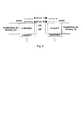
図1は、通信システム10の例である。具体的には、通信システム10は、リンク5により接続された第1トランシーバー100および第2トランシーバー200を備えている。トランシーバー100は、ステート長決定モジュール110、ステート長照合モジュール120、メモリ130ならびにメッセージモジュール140、を備えている。トランシーバー200は、ステート長決定モジュール210、ステート長照合モジュール220、メモリ230ならびにメッセージモジュール240、を備えている。
【0020】
本発明のシステム並びに方法の例を、デジタル加入者線通信システム等の加入者線との関係で説明する。しかし、本発明について、不要なあいまいさを避けるため、以下の説明においては、ブロックダイヤグラムの形式で示され、あるいは、要約されている既知の構成ならびに装置についての説明を省略する。説明の便宜上、本発明について完全な理解を提供するため、特定の具体例がいくつか述べられている。しかし、本発明は、かかる特定の具体例を超えて実施できることを理解すべきである。例えば、本発明のシステム並びに方法は、例えば、IEEES02システムに基づく無線LAN等の無線通信システム、電力線通信システム、または、他のどのような、あるいは、マルチキャリア通信を用いるシステムの組み合わせ、もしくは、その長さがトランシーバーによって制御される初期化ステートを有するいずれの変調方式を含む、どのような通信システムにも広く適用可能である。
【0021】
また、ここで示した実施形態は、通信システムに配置された様々な部品を示しているが、かかるシステムの様々な部品は、電気通信網および/またはインターネット等の配信ネットワークの離れた部分、あるいは、専用の可変ステート長・初期化システム内に配置可能であることが理解される。したがって、通信システムの部品を、一以上の装置として合体させ、あるいは、電気通信網等の配信ネットワークの特定ノードに位置させることができる、ことが理解されよう。以下の説明から理解されるとともに、計算の効率の観点から、通信システムの部品は、システムの動作に影響を及ぼすことないよう、配信ネットワーク内のいずれの場所に配置することが可能である。
【0022】
また、エレメントを接続する様々なリンクは、有線または無線範囲(wired or wireless lenghts)のいずれか、あるいは、これらの組み合わせ、ないしは、接続されたエレメントに対しデータを供給し、および/または、そことのデータのやりとりが可能である他のいずれの既知あるいは将来開発されるエレメントであってもよいこと、を理解すべきである。さらに、ここで用いられているモジュールという用語は、いずれの既知あるいは将来開発されるハードウエア、ソフトウエアまたはハードウエアとソフトウエアの組み合わせであって、そのエレメントの機能を実行可能なもの、を指す。
【0023】
図1の通信システム10は、ATU−CおよびATU−Rとしての2のトランシーバー100および200を表している。かかる2のトランシーバー間の通信は、リンク5を介して行われる。しかし、2のトランシーバー100および200間での定常状態での通信を行う前に、初期化を実行しなければならない。
【0024】
具体的には、上述のように、初期化は、例えば、様々なパラメーターを検出し、識別し、信号処理機能を訓練し、2のトランシーバー間の通信を確立させること、等を可能にするようトランシーバーを訓練するため用いられる。しかし、特定の初期化ステートでは、初期化ステートのトレーニング機能を完全に実行するため、送信用および/または受信用の特定の数のDMT記号、を要する。
【0025】
図1に示す実施形態の動作例について、トランシーバー100をATU−Cとし、トランシーバー200をATU−Rとした場合を例に説明する。かかる実施形態の動作例において、プロトコルならびに方法は、ATU−Cが送信トランシーバーであり、ATU−Rが受信トランシーバーである場合のステートの長さを制御するため用いられる。かかる例は、C−REVERB1の長さの制御との関連において上で説明されている。また、かかる実施形態の例は、以下で述べるように、選択されたステート用のDMT記号の最小数量を決定するトランシーバー100、または、選択されたステート用のDMT記号の最小数量を決定するトランシーバー200、あるいは、選択されたステート用のDMT記号の最小数量を決定するとともに、受信、送信されたDMT記号の数を監視するトランシーバー100およびトランシーバー200の両方との関連において説明される。
【0026】
具体的には、動作中、ステート長決定モジュール110は、もしあれば、選択されたステート用のDMT記号の最小数量を決定する。メッセージモジュール140は、決定されたMinStateに基づき、通信リンク5を介し、MinStateステート値50をトランシーバー200に送る。トランシーバー200は、ステート長照合モジュール220ならびにメモリ230と協力して、トランシーバー100から受信したDMT記号を監視する。ステート長照合モジュール220が少なくとも特定のDMT記号の最小値を受信すると、当該ステート長照合モジュール220は、トランシーバー100により信号が検出された場合に、トランシーバー100が現在の初期化ステートを出て新しい初期化ステートに入るよう、トランシーバー200がトランシーバー100に対し、信号を送信するのを認証する。例えば、前記信号に基づき、自動的に新しい初期化ステートに入るようトランシーバー200並びにトランシーバー100を予めプログラムしておいてもよい。これに代え、トランシーバー200は、リンク5を介し、トランシーバー100に対し、次の初期化ステートに入ることを要求するメッセージを送ることもできる。
【0027】
また、これに代え、トランシーバー200は、特定の初期化ステートのMinState値25を特定することもできる。具体的には、ステート長決定モジュール210が、選択されたステート(MinState)のDMT記号の最小値を決定する。次に、メッセージモジュール240と協力して、MinState値を識別する情報が、リンク5を介して、トランシーバー100に送られ、例えば、メモリ130に記憶される。さらに、トランシーバー100は、ステート長照合モジュール120と協力して、現在の初期化ステートと関連づけてトランシーバー200に対して送信されたDMT記号を監視する。前記ステート長照合モジュール120が少なくとも特定数のDMT記号を送信すると、当該ステート長照合モジュール120は、トランシーバー200の受信部によってそれが検出された場合には、トランシーバー200に現在の初期化ステートを終了し、新しい初期化ステートの開始に移行することを示す信号を、トランシーバー100がトランシーバー200に対して送信することを認証する。
【0028】
図2は、上述のC−REVERB1ステートに基づき、本発明の一実施形態に基づき、やりとりされている通信を表している。具体的には、ATU−Cは、MinState値を識別するメッセージまたは識別子等の情報を、当該ステートの最低長を表示するATU−Rへ送る。例えば、ATU−Cは、前記MinState値が、C−REVERB1ステート250用の1000のDMT記号と等しいことを表す情報を送ることもできる。かかる例において、ATUーRは、ATU−R送信機が、ATU−Cに対しR−REVERB2を送信する前に、例えば、少なくとも1000のDMT記号分待機することを要求する。ATU−Cに対してR−REVERB2を送ることにより、C−REVERB1ステートを終了させることになる。
【0029】
これに代え、図3に示すように、ATU−R受信機が、ATUーCに対して所望の長さのステートを送り、ATUーCは、例えば、終了されたステートにおいて送信された信号に対して反対(逆)の極性を有する信号等の既知の信号を、ATU−R受信機に送ることにより、そのステートを終了させるようにしてもよい。
【0030】
上述の例から、C−REVERB1ステートを用いることにより、ATU−Rは、ATU−Cに対し、ステート260の最小長、例えば、MinState値を表わす識別子またはメッセージ等の情報を送信する。例えば、ATU−Rは、前記MinStateが、C−REVERB1ステート用の1000のDMT記号と等しいこと、を表示することもできる。この場合、ATU−Cは、ATU−C送信機がC−SEGUE1等の既知の信号をATU−Rに送信し、それによりC−REVERB1ステートが終了される前に、少なくとも1000のDMT記号分待機するよう要求される。
【0031】
さらに、これに代え、図4は、ATU送信機並びにATU受信機が所望の長さのステート270および280を互いに送信しあう実施形態の例を表している。この例の場合、現在のステートからの移行を決定するため、二つのMinState値の大きい方の数が用いられ、これにより、両方のトランシーバーがステート長を知ることになるので、当該ステートを終了させる信号は不要となる。しかしながら、特定の実施形態においては、ステートの終了信号を含むことが好ましいことが理解されよう。上述の実施形態のように、この終了信号は、ATU−RまたはATU−Cのいずれから送るようにしてもよい。
【0032】
上記例から、動作中にC−REVERB1ステートを用いることにより、ATU−Rは、ATU−Cに対し、受信機のステートの最小長さ(Min-State-Rx)を表わすメッセージを送る。例えば、ATU−Rは、Min-state-Rxが、C−REVERB1用の2000のDMT記号と等しいことを表すこともできる。同様に、ATU−Cは、ATU−Rに対し、ATU送信機のステートの最小の長さ(MinState-Tx)を表すメッセージ等の情報を送信することもできる。例えば、かかるATU−Cは、MinState-Txが、C−REVERB1用の1000のDMT記号と等しいことを表すこともできる。したがって、C−REVERB1の時間は、MinState-TxならびMin-State-Rxの長さの大きい方と等しい。この例において、C−REVERB1の長さが2000のDMT記号であると特定されるので、その長さは、前記2つの大きい方が選ばれる。
【0033】
さらに、上記実施形態は、第一のトランシーバーから第二のトランシーバーへ、ステート長を変更する要求を一つだけ送ることについて説明されているが、一以上のトランシーバーが、他のトランシーバーに対する一の通信における複数のステートについてのMinState値を特定可能であること、が理解されよう。例えば、複数のステートについてのMinState値をメモリ内に記憶することもでき、次の初期化ステートに切り換えるための決定がなされると、トランシーバーは、当該ステートについての初期化を正確に行うのに必要なMinState値を有する。
【0034】
例示した実施形態では、ATU−Cであるトランシーバー100並びにATU−Rであるトランシーバー200を用いて説明されていたが、トランシーバー200がATU−Cとなり、トランシーバー100がATU−Rとなるよう切り換え可能である。かかる代替実施形態において、そのプロトコル並びに方法は、ATU−Rが送信トランシーバーであり、ATU−Cが受信トランシーバーである場合のステートの長さを制御するために用いられる。かかる例は、R−REVERB3の長さの制御についての上記説明で述べられている。
【0035】
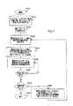
図5は、本発明にかかる初期化ステート長の変更の実施形態の例を示す。具体的には、制御は、ステップS100から始まりステップS110に続く。ステップS110においては、どのステートが、DMT記号の最小数を要求するかについての判断がなされる。次に、ステップS120において、第一の初期化ステートが選択される。続いて、ステップS130では、選択されたステートがDMT記号の最小数を要求し、選択されたステート用のDMT記号の最小数が決定される、と仮定する。次に、ステップS140に進む。
【0036】
ステップS140においては、、選択されたステート用のDMT記号の最小数を特定するメッセージ、特定の信号あるいは識別子等の情報が組み合わされ、第2トランシーバーに送られる。次に、ステップS150においては、第2トランシーバーにより受信あるいは送信されたDMT記号であって、選択されたステートに関連づけられたもの、の数が監視される。さらに、ステップS160において、前記受信あるいは送信されたDMT記号の数がMinState 長以上である場合、ステップS170に進む。そうでない場合は、ステップS150に戻る。
【0037】
ステップS170においては、初期化が完了したかどうかの判断がなされる。初期化が完了した場合、トランシーバーが定常通信ステート(steady-state communication)に入る等、初期化が終了するステップS180に進む。そうでない場合、第1トランシーバーに対し、例えば、現在の初期化ステートを出て他の初期化ステートに入ることを可能とする特定の所定信号である情報、が送られるステップS190に進み、次に、ステップS130に戻る。
【0038】
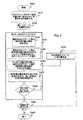
図6は、ATU−C並びにATU−Rの両方が、選択されたステート用のMinState値を特定する実施形態の第二の例を概説する。具体的には、制御はステップS200で始まり、ステップS210へと続く。ステップS210においては、どのステートがDMT記号の最小数(MinState)を要求するについて判断がなされる。次に、ステップS220において、第一の初期化ステートが選択される。さらに、ステップS230において、ATU−C並びにATU−Rについて、以下のステップが実行される。
【0039】
具体的には、ステップS240において、選択されたステート用のDMT記号の最小数が決定される。次に、ステップS250において、選択されたステート用のDMT記号の最小数を特定するメッセージあるいは識別子等の情報が組み合わされ、他のトランシーバーに送られる。次に、更にステップS260において、ATU−Rによって送られたMinState値並びにATU−Cによって送られたMinState値と、選択された2つのMinState値(MaxMinState)の大きい方の値との比較が行われる。次に、ステップS270に進む。
【0040】
ステップS270において、ATU−C並びにATU−Rのそれぞれは、受信あるいは送信されたDMT記号の数を監視する。次に、ステップS280において、MaxMinState値に達したかどうかの判断がなされる。MaxMinStateに達していない場合、ステップS290に進む。そうでない場合は、ステップS270に戻る。
ステップS290において、初期化が完了したかどうかの判断がなされる。初期化が完了した場合、制御シーケンスが終了するステップS300に進む。そうでない場合、ATU−C並びにATU−Rが次の初期化ステートに切り換えられるステップS310に戻る
上記の初期化プロトコルは、モデム、DSLモデム、ADSLモデム、マルチキャリアトランシーバー等の電気通信装置上、あるいは、通信装置を有する独立したプログラム済汎用コンピュータ上、で実行可能である。しかし、本発明のシステム並びに方法は、特殊用途のコンピュータ、プログラム済マイクロプロセッサまたはマイクロコントローラおよび周辺集積回路素子、ASIC又は他の集積回路、デジタル信号プロセッサ、個別素子回路(discrete element circuit)等の配線電気回路又は配線論理回路、PLD、PLA、FPGA、PAL、モデム等のプログラム済論理回路によっても実現することが可能である。通常、ここで示すフローチャートを実行可能なステートマシン(state machine)を実現可能であれば、どのような装置であっても本発明にかかる初期化ステート長可変システムを実現するために用いることが可能である。
【0041】
さらに、開示された方法は、様々なコンピュータ、ワークステーション・ハードウエアプラットホームに使用可能なポータブル・ソースコードを提供するオブジェクト、またはオブジェクト指向のソフトウエア開発環境、を用いたソフトウエアによって直ちに実現することができる。これに代えて、開示された初期化ステート長可変システムは、標準的な論路回路又はVLSI設計を用いることにより、その一部又は全部をハードウエアによって実現することができる。本発明にかかるシステムを実現するためにハードウエアまたはソフトウエアのいずれを用いるかは、システムの速度および/または効率要件、特定の機能、および、用いられる特定のソフトウエア又はハードウエアシステムまたはマイクロプロセッサー、あるいはマイクロプロセッサーシステムによる。しかし、ここで示す初期化ステート長可変システムおよび方法は、ここでなされた機能に関する説明およびコンピュータ及び通信技術に関する基本的な知識から、それらが適用可能な技術の当業者により、既知の又は将来開発されるどのようなシステム又は構造、装置および/又はソフトウエアを用いることによっても、ハードウエアおよび/又はソフトウエアにより直ちに実現することが可能である。
【0042】
さらに、開示された方法は、プログラム済の汎用コンピュータ、専用コンピュータ、マイクロプロセッサー等の上でソフトウエアとして直ちに実行することができる。これらの場合、本発明の方法およびシステムは、パーソナルコンピュータ内に内蔵されたJava商標又はCGIスクリプト等のプログラム、サーバー又はグラフィックワークステーション内に存するリソース、初期化ステート長可変機能を搭載した専用の受信トランシーバー等に内蔵されているルーチン、として実現することができる。かかる初期化ステート長可変システムは、前記システムと前記方法を、初期化ステート長の変更が可能なトランシーバーのハードウエアおよびソフトウエアシステム等のソフトウエアおよび/又はハードウエアシステム中に物理的に組み込むことによっても実現可能である。
【0043】
したがって、本発明によると、可変ステート長・初期化システムおよび方法が提供されることが明らかである。本発明は、いくつかの実施形態に関して説明がなされているが、適用可能な技術の当業者にとっては、多くの代替手段、変更例があることは、明らかに理解できる。したがって、出願人は、本発明の精神およびの範囲中にある、かかる代替手段、変更例、均等物を包むことを意図している。
【図面の簡単な説明】
【0044】
【図1】図1は、本発明にかかる通信システムの例を表す機能ブロック図である。
【図2】図2は、本発明にかかる、2のモデム間の通信の例を表す機能ブロック図である。
【図3】図3は、本発明の第二実施形態にかかる、2のモデム間の通信の例を表す機能ブロック図である。
【図4】図4は、本発明の第三実施形態にかかる、2のモデム間の通信の例を表す機能ブロック図である。
【図5】本発明にかかる初期化ステート長の変更を実行するフローチャートの概要である。
【図6】本発明にかかる初期化ステート長の変更を実行する第二実施形態のフローチャートの概要である。[Related application data]
[0001]
No. 60 / 296,697, filed Jun. 7, 2001, entitled "Initialization with Variable State Length", which is incorporated herein by reference in its entirety. Claim the benefit of priority under section 119 (e).
【Technical field】
[0002]
The systems and methods of the present invention generally relate to communication systems. In particular, the systems and methods of the present invention relate to providing initialization with a variable state length.
[Description of the Prior Art]
[0003]
In multi-carrier modulation, also known as discrete multi-tone transmission (DMT), the transceiver goes through a number of initialization states before entering a steady state communication or "showtime". Such multiple states include channel detection, transceiver training, channel analysis, and the like. Such various initialization states may be used to determine the transmitter's transmit power level, train line characteristics, receive functions such as an equalizer or echo canceller, or other features needed to establish communication, or between transceivers. Exchange of parameters and settings.
DISCLOSURE OF THE INVENTION
[0004]
DSL (Digital Subscriber Line) modems use a variable length initialization state for ADSL communications. ITU's ADSL standard G., which is incorporated herein by reference in its entirety. 992.1 and G.I. 992.2 specifies the operation of a conventional ADSL system. For example, in the “Multi-Company Prposal for Initialization”, which is incorporated herein by reference in its entirety, the C-REVERB1 initialization state and the R-REVERB3 initialization state are: Variable length. The length of a state is defined as the number of DMT symbols transmitted in that state where the DMT symbol is also recognized as a multi-carrier symbol. The length of the C-REVERB1 initialization state is controlled by ATU-R (ATU-R-ADSL transceiver unit-remote), and the length of R-REVERB3 is controlled by ATU-C (ADSL transceiver unit-base station). Is done. In this example, the ATU-C transmitter continues to transmit C-REVERB1 until the ATU-C receiver detects R-REVERB2 sent from ATU-R. Similarly, the ATU-R transmitter continues transmitting R-REVERB3 until the ATU-R receiver detects C-REVERB2 sent from the ATU-C transmitter. For example, when the ATU-C receiver receives the R-REVERB3 signal for a sufficient time, the ATU-C transmitter transmits the C-REVERB2 signal once detected by the ATU-R to the ATU-R, -Leave the R transmitter out of the R-REVERB3 state. Similarly, when the ATU-R receiver receives the C-REVERB1 signal for a sufficient time, the ATU-R transmitter transmits the R-REVERB2 signal once detected by the ATU-C receiver to the ATU-C. Then, the ATU-C transmitter exits the R-REVERB3 state.
[0005]
For example, to perform adaptive signal processing such as equalizer training and frame synchronization, the ATU-C receiver uses the R-REVERB3 signal, and the ATU-R receiver uses the C-REVERB1 signal. It is important for the R receiver and the ATU-C receiver to control the state length. Generally, this method of having the ATU receiver control the length of the initialization state is used in G992.2 and G992.1 for ADSL in the ITU standard.
[0006]
However, this method has at least one problem of not giving the ATU transmitter the ability to control the state length. This is a problem since ATU transmitters often use these signals also to perform local adaptive signal processing, adaptive analog processing functions, and the like. For example, an ATU-C transmitter can use the C-REVERB1 signal to train a local analog or digital echo canceller. In this example, the ATU-C does not have enough time to complete the training of the echo canceller, so if it is determined and managed by the ATU-R, the ATU-C will maintain control of the state length. It is important to.
[0007]
As a result, example embodiments of the present invention allow, for example, both an ATU transmitter and an ATU receiver to control the length of one or more initialization states. For example, the ATU transmitter can transmit information, such as a message, to the ATU receiver before or during the variable initialization state. Such information can specify the minimum length of the initialization state required by the ATU transmitter. When an ATU receiver wants to end a state, as in conventional ADSL, the ATU receiver controls the length of the state by sending certain signals to other ATUs.
[0008]
Using the above example, based on the C-REVERB1 state, the ATU sends a message to the ATU-R indicating the minimum state length "MinState" before or during entering the C-REVERB1 state. For example, ATU-C may indicate that MinState is equal to 1000 DMT symbols for the C-REVERB1 state. In such a case, the ATU-R transmitter waits, for example, for at least 1000 DMT symbols before transmitting R-REVERB2 to ATU-C, thereby ending the C-REVERB1 state.
[0009]
One aspect of the present invention relates to multi-carrier modulation communication.
[0010]
Another aspect of the present invention is to change the length of an initialization state in a multicarrier modulation communication system.
[0011]
Aspects of the invention relate to the length of the initialization state controlled by ATU-C as well as ATU-R.
[0012]
Aspects of the present invention also relate to the length of the initialization state controlled by the transmitter.
[0013]
Further aspects of the invention relate to the length of the initialization state controlled by the receiver.
[0014]
Aspects of the invention relate to the length of an initialization state controlled by an ATU transmitter and / or receiver.
[0015]
Further, an aspect of the present invention relates to exchange of information defining a state length between transceivers.
[0016]
Further aspects of the invention relate to proceeding to the next initialization state based at least on completion of the variable state length initialization procedure.
[0017]
The above and other features and advantages of the invention will be set forth in the following detailed description of the embodiments.
Described or clarified thereby.
[0018]
The details of the present invention will be described with reference to the accompanying drawings.
[0019]
FIG. 1 is an example of a communication system 10. Specifically, the communication system 10 includes a
[0020]
Examples of the systems and methods of the present invention are described in the context of a subscriber line, such as a digital subscriber line communication system. However, in order to avoid unnecessary ambiguity with respect to the present invention, descriptions of well-known structures and devices that are shown in the form of block diagrams or summarized in the following description are omitted. For purposes of explanation, certain specific examples are set forth in order to provide a thorough understanding of the present invention. However, it should be understood that the present invention can be practiced beyond such specific embodiments. For example, the system and method of the present invention may be a wireless communication system such as a wireless LAN based on the IEEE02 system, a power line communication system, or any other combination of systems using multi-carrier communication, or a combination thereof. It is widely applicable to any communication system, including any modulation scheme having an initialization state whose length is controlled by the transceiver.
[0021]
Also, while the embodiments described herein show various components located in a communication system, various components of such a system may be separate portions of a distribution network, such as a telecommunications network and / or the Internet, or , It can be placed in a dedicated variable state length and initialization system. Thus, it will be appreciated that components of a communication system may be combined as one or more devices or located at a particular node in a distribution network, such as a telecommunications network. As will be understood from the following description, and in terms of computational efficiency, the components of the communication system can be located anywhere in the distribution network so as not to affect the operation of the system.
[0022]
Also, the various links connecting the elements may provide data to connected elements, either in wired or wireless lenghts, or a combination thereof, and / or It should be understood that any other known or later-developed element capable of exchanging this data may be used. Further, the term module, as used herein, refers to any known or future developed hardware, software or combination of hardware and software that can perform the functions of that element. .
[0023]
The communication system 10 of FIG. 1 represents two
[0024]
Specifically, as described above, the initialization may, for example, allow for detecting and identifying various parameters, training signal processing functions, establishing communication between the two transceivers, and the like. Used to train transceivers. However, certain initialization states require a certain number of DMT symbols for transmission and / or reception in order to fully perform the training function of the initialization state.
[0025]
The operation example of the embodiment shown in FIG. 1 will be described with an example in which the
[0026]
Specifically, in operation, state
[0027]
Alternatively, the
[0028]
FIG. 2 illustrates communications being exchanged based on the C-REVERB1 state described above and according to one embodiment of the present invention. Specifically, the ATU-C sends information such as a message or an identifier for identifying the MinState value to the ATU-R indicating the minimum length of the state. For example, ATU-C may send information indicating that the MinState value is equal to 1000 DMT symbols for C-
[0029]
Alternatively, as shown in FIG. 3, the ATU-R receiver sends a state of a desired length to the ATU-C, and the ATU-C transmits, for example, a signal transmitted in the terminated state. Alternatively, a known signal such as a signal having the opposite (opposite) polarity may be sent to the ATU-R receiver to end the state.
[0030]
From the above example, by using the C-REVERB1 state, the ATU-R sends the ATU-C information such as the minimum length of the state 260, for example, an identifier or a message indicating the MinState value. For example, the ATU-R may indicate that the MinState is equal to 1000 DMT symbols for the C-REVERB1 state. In this case, the ATU-C may wait at least 1000 DMT symbols before the ATU-C transmitter sends a known signal, such as C-SEGUE1, to the ATU-R, thereby terminating the C-REVERB1 state. Be asked to do so.
[0031]
Further, alternatively, FIG. 4 illustrates an example embodiment in which the ATU transmitter and the ATU receiver transmit
[0032]
From the above example, by using the C-REVERB1 state during operation, the ATU-R sends a message to the ATU-C indicating the minimum length of the receiver state (Min-State-Rx). For example, ATU-R may indicate that Min-state-Rx is equal to 2000 DMT symbols for C-REVERB1. Similarly, the ATU-C can transmit information such as a message indicating the minimum length (MinState-Tx) of the state of the ATU transmitter to the ATU-R. For example, such an ATU-C may indicate that MinState-Tx is equal to 1000 DMT symbols for C-REVERB1. Therefore, the time of C-REVERB1 is equal to the larger of the lengths of MinState-Tx and Min-State-Rx. In this example, since the length of C-REVERB1 is specified to be 2000 DMT symbols, the longer of the two is selected.
[0033]
Further, while the above embodiments describe sending only one request to change the state length from the first transceiver to the second transceiver, one or more transceivers may communicate in one communication to another transceiver. It will be appreciated that MinState values for multiple states in can be specified. For example, the MinState values for multiple states could be stored in memory, and once a decision was made to switch to the next initialization state, the transceiver would need to correctly initialize for that state. MinState value.
[0034]
Although the illustrated embodiment has been described using the ATU-
[0035]
FIG. 5 shows an example of an embodiment of changing the initialization state length according to the present invention. Specifically, control starts from step S100 and continues to step S110. In step S110, a determination is made as to which state requires a minimum number of DMT symbols. Next, in step S120, a first initialization state is selected. Subsequently, it is assumed in step S130 that the selected state requires a minimum number of DMT symbols and that the minimum number of DMT symbols for the selected state is determined. Next, the process proceeds to step S140.
[0036]
In step S140, a message specifying the minimum number of DMT symbols for the selected state, a specific signal or information such as an identifier is combined and sent to the second transceiver. Next, in step S150, the number of DMT symbols received or transmitted by the second transceiver that are associated with the selected state is monitored. Further, when the number of the received or transmitted DMT symbols is equal to or more than the MinState length in step S160, the process proceeds to step S170. Otherwise, the process returns to step S150.
[0037]
In step S170, it is determined whether the initialization has been completed. When the initialization is completed, the process proceeds to step S180 where the initialization is completed, such as the transceiver entering a steady-state communication state. If not, the process proceeds to step S190 where the first transceiver is sent, for example, information which is a specific predetermined signal allowing to exit the current initialization state and enter another initialization state, Then, the process returns to step S130.
[0038]
FIG. 6 outlines a second example of an embodiment in which both ATU-C and ATU-R specify a MinState value for a selected state. Specifically, control starts in step S200 and continues to step S210. In step S210, a determination is made as to which state requires a minimum number of DMT symbols (MinState). Next, in step S220, a first initialization state is selected. Further, in step S230, the following steps are executed for ATU-C and ATU-R.
[0039]
Specifically, in step S240, the minimum number of DMT symbols for the selected state is determined. Next, in step S250, information such as a message or identifier specifying the minimum number of DMT symbols for the selected state is combined and sent to another transceiver. Next, in step S260, a comparison is made between the MinState value sent by the ATU-R and the MinState value sent by the ATU-C, and the larger of the two selected MinState values (MaxMinState). . Next, the process proceeds to step S270.
[0040]
In step S270, each of ATU-C and ATU-R monitors the number of DMT symbols received or transmitted. Next, in step S280, a determination is made whether the MaxMinState value has been reached. If MaxMinState has not been reached, the process proceeds to step S290. Otherwise, the process returns to step S270.
In step S290, a determination is made whether the initialization has been completed. When the initialization is completed, the process proceeds to step S300 where the control sequence ends. Otherwise, return to step S310 where the ATU-C and ATU-R are switched to the next initialization state.
The above initialization protocol can be executed on a telecommunication device such as a modem, DSL modem, ADSL modem, multi-carrier transceiver, or on a separate programmed general purpose computer with a communication device. However, the systems and methods of the present invention may be implemented in special purpose computers, programmed microprocessors or microcontrollers and peripheral integrated circuit devices, ASICs or other integrated circuits, digital signal processors, discrete element circuits, etc. It can also be realized by a programmed logic circuit such as an electric circuit or a wiring logic circuit, a PLD, a PLA, an FPGA, a PAL, and a modem. In general, any device that can realize a state machine capable of executing the flowchart shown here can be used to realize the variable initialization state length system according to the present invention. It is.
[0041]
Further, the disclosed method is readily implemented by software using objects that provide portable source code usable on various computers, workstation hardware platforms, or object-oriented software development environments. Can be. Alternatively, some or all of the disclosed variable initialization state length systems can be implemented in hardware using standard logic circuits or VLSI designs. Whether hardware or software is used to implement a system according to the invention depends on the speed and / or efficiency requirements of the system, the particular functionality, and the particular software or hardware system or microprocessor used. Or by a microprocessor system. However, the variable initialization state length systems and methods described herein are well known or future developed by those skilled in the art to which they can be applied, given the description of the functions made herein and the basic knowledge of computer and communication technologies. Any system or structure, device, and / or software that is implemented can be readily implemented in hardware and / or software.
[0042]
Moreover, the disclosed methods can be readily implemented as software on a programmed general purpose computer, special purpose computer, microprocessor, or the like. In these cases, the method and system of the present invention may include a program such as a Java trademark or CGI script embedded in a personal computer, a resource residing in a server or graphic workstation, a dedicated reception with a variable initialization state length function. It can be realized as a routine built in a transceiver or the like. Such a variable initialization state length system physically integrates the system and the method into a software and / or hardware system, such as a hardware and software system of a transceiver capable of changing the initialization state length. It is also feasible.
[0043]
Thus, it is apparent that there has been provided, in accordance with the present invention, a variable state length and initialization system and method. Although the present invention has been described in terms of several embodiments, it will be apparent to those skilled in the applicable art that there are many alternatives and modifications. Accordingly, applicants intend to cover such alternatives, modifications, and equivalents, which are within the spirit and scope of the invention.
[Brief description of the drawings]
[0044]
FIG. 1 is a functional block diagram illustrating an example of a communication system according to the present invention.
FIG. 2 is a functional block diagram illustrating an example of communication between two modems according to the present invention.
FIG. 3 is a functional block diagram illustrating an example of communication between two modems according to a second embodiment of the present invention.
FIG. 4 is a functional block diagram illustrating an example of communication between two modems according to a third embodiment of the present invention.
FIG. 5 is an outline of a flowchart for executing a change of an initialization state length according to the present invention.
FIG. 6 is an outline of a flowchart of a second embodiment for changing the initialization state length according to the present invention.
Claims (90)
Translated fromJapanese前記第一マルチキャリアトランシーバーから前記第二マルチキャリアトランシーバーに対し、初期化ステートにおけるマルチキャリア記号の最小数を識別する情報を送信するステップ、
前記第一マルチキャリアトランシーバーから前記第二マルチキャリアトランシーバーに対し、前記初期化ステートの間、少なくとも前記マルチキャリア記号の最小数を送信するステップ、および、
前記第二マルチキャリアトランシーバーから前記第一マルチキャリアトランシーバーに対し、前記第一マルチキャリアトランシーバーが前記初期化ステートを出て新しい初期化ステートに入ることを可能とする所定の信号を送信するステップ、を備え、
前記所定信号は、前記第二マルチキャリアトランシーバーが前記初期化ステートにおいて少なくともマルチキャリア記号の最小数を受信した後に、前記第二マルチキャリアトランシーバーから前記第一マルチキャリアトランシーバーに送信されること、
を特徴とするもの。A method for changing an initialization state length in a multicarrier communication system including a first multicarrier transceiver and a second multicarrier transceiver,
Transmitting information identifying the minimum number of multicarrier symbols in an initialization state from the first multicarrier transceiver to the second multicarrier transceiver;
Transmitting at least a minimum number of the multi-carrier symbols from the first multi-carrier transceiver to the second multi-carrier transceiver during the initialization state; and
Transmitting from the second multi-carrier transceiver to the first multi-carrier transceiver a predetermined signal that allows the first multi-carrier transceiver to exit the initialization state and enter a new initialization state. Prepare
The predetermined signal is transmitted from the second multicarrier transceiver to the first multicarrier transceiver after the second multicarrier transceiver receives at least a minimum number of multicarrier symbols in the initialization state,
Characterized by:
を特徴とするもの。2. The method of claim 1, wherein a minimum number of multi-carrier symbols in the initialization state is less than a predetermined maximum number of multi-carrier symbols for the initialization state.
Characterized by:
を特徴とするもの。The method of claim 1, wherein the information is at least one of an identifier, a signal, and a message;
Characterized by:
第二マルチキャリアトランシーバーに対し、初期化ステートにおけるマルチキャリア記号の最小数を識別する情報を送信するステップ、
第二マルチキャリアトランシーバーに対し、前記初期化ステートの間、少なくとも前記マルチキャリア記号の最小数を送信するステップ、および
前記第二マルチキャリアトランシーバーから、前記初期化ステートを出て新しい初期化ステートに入ることを可能とする所定の信号を受信するステップ、を備え、
前記所定信号は、前記初期化ステートにおいて少なくとも前記マルチキャリア記号の最小数を送信した後に、前記第二マルチキャリアトランシーバーから受信されること、
を特徴とするもの。A method of changing an initialization state length in a multi-carrier transceiver,
Transmitting to the second multi-carrier transceiver information identifying a minimum number of multi-carrier symbols in the initialization state;
Transmitting at least a minimum number of the multi-carrier symbols during the initialization state to a second multi-carrier transceiver; and exiting the initialization state and entering a new initialization state from the second multi-carrier transceiver. Receiving a predetermined signal that enables
The predetermined signal is received from the second multicarrier transceiver after transmitting at least the minimum number of the multicarrier symbols in the initialization state.
Characterized by:
を特徴とするもの。5. The method of claim 4, wherein a minimum number of the multi-carrier symbols in the initialization state is less than a predetermined maximum number of multi-carrier symbols for the initialization state.
Characterized by:
を特徴とするもの。5. The method of claim 4, wherein the information is at least one of an identifier, a signal, and a message.
Characterized by:
第二マルチキャリアトランシーバーから、初期化ステートにおけるマルチキャリア記号の最小数を識別する情報を受信するステップ、
第二マルチキャリアトランシーバーから、前記初期化ステートの間、少なくとも前記マルチキャリア記号の最小数を受信するステップ、および
前記第二マルチキャリアトランシーバー対し、前記初期化ステートを出て新しい初期化ステートに入ることを可能とする所定の信号を送信するステップ、を備え、
前記所定信号は、前記初期化ステートにおいて少なくとも前記マルチキャリア記号の最小数を受信した後に、前記第二マルチキャリアトランシーバーに送信されること、
を特徴とするもの。A method of changing an initialization state length in a multi-carrier transceiver,
Receiving from the second multi-carrier transceiver information identifying a minimum number of multi-carrier symbols in the initialization state;
Receiving at least a minimum number of the multi-carrier symbols from the second multi-carrier transceiver during the initialization state; and exiting the initialization state and entering a new initialization state for the second multi-carrier transceiver. Transmitting a predetermined signal that enables
The predetermined signal is transmitted to the second multi-carrier transceiver after receiving at least the minimum number of the multi-carrier symbols in the initialization state,
Characterized by:
を特徴とするもの。8. The method of claim 7, wherein the minimum number of multi-carrier symbols in the initialization state is less than a predetermined maximum number of multi-carrier symbols for the initialization state.
Characterized by:
を特徴とするもの。The method of claim 7, wherein the information is at least one of an identifier, a signal, and a message;
Characterized by:
前記第一マルチキャリアトランシーバーから前記第二マルチキャリアトランシーバーに対し、初期化ステートにおけるマルチキャリア記号の最小数を識別する情報を送信するステップ、
前記第二マルチキャリアトランシーバーから前記第一マルチキャリアトランシーバーに対し、前記初期化ステートの間、少なくとも前記マルチキャリア記号の最小数を送信するステップ、および、
前記第二マルチキャリアトランシーバーから前記第一マルチキャリアトランシーバーに対し、前記初期化ステートを出て新しい初期化ステートに入ることを示す所定の信号を送信するステップ、を備え、
前記所定信号は、前記第二マルチキャリアトランシーバーが前記初期化ステートにおいて少なくともマルチキャリア記号の最小数を送信した後に、前記第二マルチキャリアトランシーバーから前記第一マルチキャリアトランシーバーに送信されること、
を特徴とするもの。A method of changing an initialization state length in a multicarrier transceiver including a first multicarrier transceiver and a second multicarrier transceiver,
Transmitting information identifying the minimum number of multicarrier symbols in an initialization state from the first multicarrier transceiver to the second multicarrier transceiver;
Transmitting at least a minimum number of the multi-carrier symbols from the second multi-carrier transceiver to the first multi-carrier transceiver during the initialization state; and
Transmitting a predetermined signal from the second multi-carrier transceiver to the first multi-carrier transceiver, the signal indicating exiting the initialization state and entering a new initialization state,
The predetermined signal is transmitted from the second multicarrier transceiver to the first multicarrier transceiver after the second multicarrier transceiver transmits at least a minimum number of multicarrier symbols in the initialization state,
Characterized by:
を特徴とするもの。11. The method of claim 10, wherein a minimum number of the multi-carrier symbols in the initialization state is less than a predetermined maximum number of multi-carrier symbols for the initialization state.
Characterized by:
を特徴とするもの。The method of claim 10, wherein the information is at least one of an identifier, a signal, and a message;
Characterized by:
第二マルチキャリアトランシーバーに対し、初期化ステートにおけるマルチキャリア記号の最小数を識別する情報を送信するステップ、
前記第二マルチキャリアトランシーバーから、前記初期化ステートの間、少なくとも前記マルチキャリア記号の最小数を受信するステップ、
前記第二マルチキャリアトランシーバーから、前記初期化ステートを出て新しい初期化ステートに入ることを示す所定の信号を受信するステップ、を備え、
前記所定信号は、前記初期化ステートにおいて少なくとも前記マルチキャリア記号の最小数を送信した後に、前記第二マルチキャリアトランシーバーから受信されること、
を特徴とするもの。A method of changing an initialization state length in a multi-carrier transceiver,
Transmitting to the second multi-carrier transceiver information identifying a minimum number of multi-carrier symbols in the initialization state;
Receiving at least a minimum number of the multi-carrier symbols from the second multi-carrier transceiver during the initialization state;
Receiving from the second multi-carrier transceiver a predetermined signal indicating exiting the initialization state and entering a new initialization state;
The predetermined signal is received from the second multicarrier transceiver after transmitting at least the minimum number of the multicarrier symbols in the initialization state.
Characterized by:
を特徴とするもの。14. The method of claim 13, wherein a minimum number of the multi-carrier symbols in the initialization state is less than a predetermined maximum number of multi-carrier symbols for the initialization state.
Characterized by:
を特徴とするもの。14. The method of claim 13, wherein the information is at least one of an identifier, a signal, and a message.
Characterized by:
第二マルチキャリアトランシーバーから、初期化ステートにおけるマルチキャリア記号の最小数を識別する情報を受信するステップ、
第二マルチキャリアトランシーバーから、前記初期化ステートの間、少なくとも前記マルチキャリア記号の最小数を送信するステップ、および
前記第二マルチキャリアトランシーバーに、前記初期化ステートを出て新しい初期化ステートに入ることを示す所定の信号を送信するステップ、を備え、
前記所定信号は、前記初期化ステートにおいて少なくとも前記マルチキャリア記号の最小数を受信した後に、前記第二マルチキャリアトランシーバーに送信されること、
を特徴とするもの。A method of changing an initialization state length in a multi-carrier transceiver,
Receiving from the second multi-carrier transceiver information identifying a minimum number of multi-carrier symbols in the initialization state;
Transmitting at least a minimum number of the multi-carrier symbols from the second multi-carrier transceiver during the initialization state; and leaving the second multi-carrier transceiver to exit the initialization state and enter a new initialization state. Transmitting a predetermined signal indicating
The predetermined signal is transmitted to the second multi-carrier transceiver after receiving at least the minimum number of the multi-carrier symbols in the initialization state,
Characterized by:
を特徴とするもの。17. The method of claim 16, wherein a minimum number of the multi-carrier symbols in the initialization state is less than a predetermined maximum number of multi-carrier symbols for the initialization state.
Characterized by:
を特徴とするもの。17. The method of claim 16, wherein the information is at least one of an identifier, a signal, and a message.
Characterized by:
前記第一マルチキャリアトランシーバーから前記第二マルチキャリアトランシーバーに対し、初期化ステートにおけるマルチキャリア記号の最小数を識別する情報を送信する手段、
前記第一マルチキャリアトランシーバーから前記第二マルチキャリアトランシーバーに対し、前記初期化ステートの間、少なくとも前記マルチキャリア記号の最小数を送信する手段、および、
前記第二マルチキャリアトランシーバーから前記第一マルチキャリアトランシーバーに対し、前記第一マルチキャリアトランシーバーが前記初期化ステートを出て新しい初期化ステートに入ることを可能とする所定の信号を送信する手段、を備え、
前記所定信号は、前記第二マルチキャリアトランシーバーが前記初期化ステートにおいて少なくともマルチキャリア記号の最小数を受信した後に、前記第二マルチキャリアトランシーバーから前記第一マルチキャリアトランシーバーに送信されること、
を特徴とするもの。A multi-carrier communication system including a first multi-carrier transceiver and a second multi-carrier transceiver, wherein an initialization state length can be changed,
Means for transmitting information identifying the minimum number of multicarrier symbols in an initialization state from the first multicarrier transceiver to the second multicarrier transceiver,
Means for transmitting at least a minimum number of the multi-carrier symbols from the first multi-carrier transceiver to the second multi-carrier transceiver during the initialization state; and
Means for transmitting a predetermined signal from the second multi-carrier transceiver to the first multi-carrier transceiver to enable the first multi-carrier transceiver to exit the initialization state and enter a new initialization state. Prepare
The predetermined signal is transmitted from the second multicarrier transceiver to the first multicarrier transceiver after the second multicarrier transceiver receives at least a minimum number of multicarrier symbols in the initialization state,
Characterized by:
を特徴とするもの。20. The system of claim 19, wherein a minimum number of multi-carrier symbols in the initialization state is less than a predetermined maximum number of multi-carrier symbols for the initialization state.
Characterized by:
を特徴とするもの。20. The system of claim 19, wherein the information is at least one of an identifier, a signal, and a message.
Characterized by:
第二マルチキャリアトランシーバーに対し、初期化ステートにおけるマルチキャリア記号の最小数を識別する情報を送信する手段、
前記第二マルチキャリアトランシーバーに対し、前記初期化ステートの間、少なくとも前記マルチキャリア記号の最小数を送信する手段、および、
前記第二マルチキャリアトランシーバーから、前記初期化ステートを出て新しい初期化ステートに入ることを可能とする所定の信号を受信する手段、を備え、
前記所定信号は、前記初期化ステートにおいて少なくともマルチキャリア記号の最小数が送信された後に、前記第二マルチキャリアトランシーバーから受信されること、
を特徴とするもの。A multi-carrier transceiver whose initialization state length can be changed,
Means for transmitting to the second multi-carrier transceiver information identifying the minimum number of multi-carrier symbols in the initialization state;
Means for transmitting to the second multi-carrier transceiver during the initialization state at least a minimum number of the multi-carrier symbols; and
Means for receiving from the second multi-carrier transceiver a predetermined signal that allows the initialization state to exit and enter a new initialization state;
The predetermined signal is received from the second multicarrier transceiver after at least a minimum number of multicarrier symbols have been transmitted in the initialization state.
Characterized by:
を特徴とするもの。23. The system of claim 22, wherein a minimum number of multi-carrier symbols in the initialization state is less than a predetermined maximum number of multi-carrier symbols for the initialization state.
Characterized by:
を特徴とするもの。23. The system of claim 22, wherein the information is at least one of an identifier, a signal, and a message.
Characterized by:
第二マルチキャリアトランシーバーから、初期化ステートにおけるマルチキャリア記号の最小数を識別する情報を受信する手段、
第二マルチキャリアトランシーバーから、前記初期化ステートの間、少なくとも前記マルチキャリア記号の最小数を受信する手段、および
前記第二マルチキャリアトランシーバー対し、前記初期化ステートを出て新しい初期化ステートに入ることを可能とする所定の信号を送信する手段、を備え、
前記所定信号は、前記初期化ステートにおいて少なくとも前記マルチキャリア記号の最小数を受信した後に、前記第二マルチキャリアトランシーバーに送信されること、
を特徴とするもの。A multi-carrier transceiver whose initialization state length can be changed,
Means for receiving, from the second multi-carrier transceiver, information identifying a minimum number of multi-carrier symbols in an initialization state;
Means for receiving at least a minimum number of the multi-carrier symbols during the initialization state from a second multi-carrier transceiver, and exiting the initialization state and entering a new initialization state for the second multi-carrier transceiver. Means for transmitting a predetermined signal that enables
The predetermined signal is transmitted to the second multi-carrier transceiver after receiving at least the minimum number of the multi-carrier symbols in the initialization state,
Characterized by:
を特徴とするもの。26. The system of claim 25, wherein a minimum number of multi-carrier symbols in the initialization state is less than a predetermined maximum number of multi-carrier symbols for the initialization state.
Characterized by:
を特徴とするもの。26. The system of claim 25, wherein the information is at least one of an identifier, a signal, and a message;
Characterized by:
前記第二マルチキャリアトランシーバーから前記第一マルチキャリアトランシーバーに対し、前記初期化ステートの間、少なくとも前記マルチキャリア記号の最小数を送信するステップ、および、
前記第二マルチキャリアトランシーバーから前記第一マルチキャリアトランシーバーに対し、前記初期化ステートを出て新しい初期化ステートに入ることを示す所定の信号を送信するステップ、を備え、
前記所定信号は、前記第二マルチキャリアトランシーバーが前記初期化ステートにおいて少なくともマルチキャリア記号の最小数を送信した後に、前記第二マルチキャリアトランシーバーから前記第一マルチキャリアトランシーバーに送信されること、
を特徴とするもの。A multi-carrier communication system including a first multi-carrier transceiver and a second multi-carrier transceiver, the length of which can be changed in an initialization state, wherein the first multi-carrier transceiver and the second multi-carrier transceiver have an Transmitting information identifying a minimum number of multicarrier symbols;
Transmitting at least a minimum number of the multi-carrier symbols from the second multi-carrier transceiver to the first multi-carrier transceiver during the initialization state; and
Transmitting a predetermined signal from the second multi-carrier transceiver to the first multi-carrier transceiver, the signal indicating exiting the initialization state and entering a new initialization state,
The predetermined signal is transmitted from the second multicarrier transceiver to the first multicarrier transceiver after the second multicarrier transceiver transmits at least a minimum number of multicarrier symbols in the initialization state,
Characterized by:
を特徴とするもの。29. The system of claim 28, wherein a minimum number of multicarrier symbols in the initialization state is less than a predetermined maximum number of multicarrier symbols for the initialization state.
Characterized by:
を特徴とするもの。29. The system of claim 28, wherein the information is at least one of an identifier, a signal, and a message.
Characterized by:
第二マルチキャリアトランシーバーに対し、初期化ステートにおけるマルチキャリア記号の最小数を識別する情報を送信する手段、
第二マルチキャリアトランシーバーから、前記初期化ステートの間、少なくとも前記マルチキャリア記号の最小数を受信する手段、および
前記第二マルチキャリアトランシーバーから、前記初期化ステートを出て新しい初期化ステートに入ることを示す所定の信号を受信する手段、を備え、
前記所定信号は、前記初期化ステートにおいて少なくとも前記マルチキャリア記号の最小数を送信した後に、前記第二マルチキャリアトランシーバーから受信されること、
を特徴とするもの。A multi-carrier transceiver whose initialization state length can be changed,
Means for transmitting to the second multi-carrier transceiver information identifying the minimum number of multi-carrier symbols in the initialization state;
Means for receiving at least a minimum number of the multi-carrier symbols during the initialization state from a second multi-carrier transceiver; and exiting the initialization state and entering a new initialization state from the second multi-carrier transceiver. Means for receiving a predetermined signal indicating
The predetermined signal is received from the second multicarrier transceiver after transmitting at least the minimum number of the multicarrier symbols in the initialization state.
Characterized by:
を特徴とするもの。32. The system of claim 31, wherein a minimum number of multi-carrier symbols in the initialization state is less than a predetermined maximum number of multi-carrier symbols for the initialization state.
Characterized by:
を特徴とするもの。29. The system of claim 28, wherein the information is at least one of an identifier, a signal, and a message.
Characterized by:
第二マルチキャリアトランシーバーから、初期化ステートにおけるマルチキャリア記号の最小数を識別する情報を受信する手段、
第二マルチキャリアトランシーバーから、前記初期化ステートの間、少なくとも前記マルチキャリア記号の最小数を送信する手段、および
前記第二マルチキャリアトランシーバーに対し、前記初期化ステートを出て新しい初期化ステートに入ることを示す所定の信号を送信する手段、を備え、
前記所定信号は、前記初期化ステートにおいて少なくとも前記マルチキャリア記号の最小数を受信した後に、前記第二マルチキャリアトランシーバーに送信されること、
を特徴とするもの。A multi-carrier transceiver whose initialization state length can be changed,
Means for receiving, from the second multi-carrier transceiver, information identifying a minimum number of multi-carrier symbols in an initialization state;
Means for transmitting at least the minimum number of the multi-carrier symbols during the initialization state from a second multi-carrier transceiver; and exiting the initialization state and entering a new initialization state for the second multi-carrier transceiver. Means for transmitting a predetermined signal indicating that,
The predetermined signal is transmitted to the second multi-carrier transceiver after receiving at least the minimum number of the multi-carrier symbols in the initialization state,
Characterized by:
を特徴とするもの。35. The system of claim 34, wherein a minimum number of multi-carrier symbols in the initialization state is less than a predetermined maximum number of multi-carrier symbols for the initialization state.
Characterized by:
を特徴とするもの。35. The system of claim 34, wherein the information is at least one of an identifier, a signal, and a message.
Characterized by:
初期化ステートにおけるマルチキャリア記号の最小数を識別する情報を送信するとともに、前記初期化ステートの間、少なくとも前記マルチキャリア記号の最小数を送信する第一マルチキャリアトランシーバー、および
前記第一マルチキャリアトランシーバーに対し、前記初期化ステートを出て新しい初期化ステートに入ることを可能とする所定の信号を送信する第二マルチキャリアトランシーバー、を備え、
前記所定信号は、前記第二マルチキャリアトランシーバーが前記初期化ステートにおいて少なくともマルチキャリア記号の最小数を受信した後に、前記第二マルチキャリアトランシーバーから前記第一マルチキャリアトランシーバーに送信されること、
を特徴とするもの。A multi-carrier communication system capable of changing an initialization state length,
A first multi-carrier transceiver for transmitting information identifying a minimum number of multi-carrier symbols in an initialization state and transmitting at least the minimum number of multi-carrier symbols during the initialization state; and A second multi-carrier transceiver that transmits a predetermined signal that allows the initialization state to exit and enter a new initialization state;
The predetermined signal is transmitted from the second multicarrier transceiver to the first multicarrier transceiver after the second multicarrier transceiver receives at least a minimum number of multicarrier symbols in the initialization state,
Characterized by:
を特徴とするもの。38. The system of claim 37, wherein a minimum number of multi-carrier symbols in the initialization state is less than a predetermined maximum number of multi-carrier symbols for the initialization state.
Characterized by:
を特徴とするもの。38. The system of claim 37, wherein the information is at least one of an identifier, a signal, and a message.
Characterized by:
初期化ステートにおいてマルチキャリア記号の最小数を識別する情報を送信するとともに、前記初期化ステートの間、少なくとも前記マルチキャリア記号の最小数を送信する第一マルチキャリアトランシーバー、および
前記初期化ステートを出て新しい初期化ステートに入ることを可能とする、第二マルチキャリアトランシーバーから受信される所定の信号、を備え、
前記所定信号は、前記初期化ステートにおいて少なくともマルチキャリア記号の最小数が送信された後に、前記第二マルチキャリアトランシーバーから受信されること、
を特徴とするもの。A multi-carrier communication system capable of changing an initialization state length,
A first multi-carrier transceiver for transmitting information identifying a minimum number of multi-carrier symbols in an initialization state and transmitting at least the minimum number of multi-carrier symbols during the initialization state; and exiting the initialization state. A predetermined signal received from the second multi-carrier transceiver, which allows to enter a new initialization state.
The predetermined signal is received from the second multicarrier transceiver after at least a minimum number of multicarrier symbols have been transmitted in the initialization state.
Characterized by:
を特徴とするもの。42. The system of claim 40, wherein a minimum number of multi-carrier symbols in the initialization state is less than a predetermined maximum number of multi-carrier symbols for the initialization state.
Characterized by:
を特徴とするもの。41. The system of claim 40, wherein the information is at least one of an identifier, a signal, and a message.
Characterized by:
第二マルチキャリアトランシーバーから、初期化ステートにおけるマルチキャリア記号の最小数を識別する情報、ならびに、前記初期化ステートの間、少なくとも前記マルチキャリア記号の最小数、を受信する受信部、
前記第二マルチキャリアトランシーバーに対し、前記初期化ステートを出て新しい初期化ステートに入ることを可能にする所定の信号、を送信する送信部、を備え、
前記所定信号は、前記初期化ステートにおいて少なくとも前記マルチキャリア記号の最小数を受信した後に、前記第二マルチキャリアトランシーバーに送信されること、
を特徴とするもの。A multi-carrier transceiver whose initialization state length can be changed,
From the second multi-carrier transceiver, information identifying the minimum number of multi-carrier symbols in the initialization state, and during the initialization state, a receiving unit that receives at least the minimum number of multi-carrier symbols
A transmission unit for transmitting a predetermined signal to the second multi-carrier transceiver, which allows the second multi-carrier transceiver to exit the initialization state and enter a new initialization state,
The predetermined signal is transmitted to the second multi-carrier transceiver after receiving at least the minimum number of the multi-carrier symbols in the initialization state,
Characterized by:
を特徴とするもの。44. The system of claim 43, wherein a minimum number of multi-carrier symbols in the initialization state is less than a predetermined maximum number of multi-carrier symbols for the initialization state.
Characterized by:
を特徴とするもの。44. The system of claim 43, wherein the information is at least one of an identifier, a signal, and a message.
Characterized by:
前記第一マルチキャリアトランシーバーから前記第二マルチキャリアトランシーバーに対し、初期化ステートにおけるマルチキャリア記号の最小数を識別する情報、ならびに、前記初期化ステートの間、少なくとも前記マルチキャリア記号の最小数、を送信する送信部、および
前記第二マルチキャリアトランシーバーから前記第一マルチキャリアトランシーバーに対し、前記初期化ステートを出て新しい初期化ステートに入ることを示す所定の信号、を送信する第二送信部、を備え、
前記所定信号は、前記第二マルチキャリアトランシーバーが前記初期化ステートにおいて少なくとも前記マルチキャリア記号の最小数を受信した後に、前記第二マルチキャリアトランシーバーから前記第一マルチキャリアトランシーバーに送信されること、
を特徴とするもの。A multi-carrier communication system including a first multi-carrier transceiver and a second multi-carrier transceiver, wherein an initialization state length can be changed,
From the first multi-carrier transceiver to the second multi-carrier transceiver, information identifying a minimum number of multi-carrier symbols in an initialization state, and at least a minimum number of the multi-carrier symbols during the initialization state. A transmitting unit that transmits, and a second signal that transmits a predetermined signal indicating that the second multicarrier transceiver exits the initialization state and enters a new initialization state, to the first multicarrier transceiver, With
The predetermined signal is transmitted from the second multicarrier transceiver to the first multicarrier transceiver after the second multicarrier transceiver receives at least the minimum number of the multicarrier symbols in the initialization state.
Characterized by:
を特徴とするもの。47. The system of claim 46, wherein a minimum number of multi-carrier symbols in the initialization state is less than a predetermined maximum number of multi-carrier symbols for the initialization state.
Characterized by:
を特徴とするもの。47. The system of claim 46, wherein the information is at least one of an identifier, a signal, and a message.
Characterized by:
第二マルチキャリアトランシーバーに対し、初期化ステートにおけるマルチキャリア記号の最小数を識別する情報を送信する送信部、
第二マルチキャリアトランシーバーから、前記初期化ステートの間、少なくとも前記マルチキャリア記号の最小数、ならびに、前記初期化ステートを出て新しい初期化ステートに入ることを示す所定の信号、を受信する受信部、を備え、
前記所定信号は、前記初期化ステートにおいて少なくとも前記マルチキャリア記号の最小数を送信した後に、前記第二マルチキャリアトランシーバーから受信されること、
を特徴とするもの。A multi-carrier transceiver whose initialization state length can be changed,
A transmitting unit that transmits information for identifying the minimum number of multicarrier symbols in the initialization state to the second multicarrier transceiver;
A receiving unit for receiving, from the second multicarrier transceiver, at least a minimum number of the multicarrier symbols during the initialization state, and a predetermined signal indicating that the mobile station exits the initialization state and enters a new initialization state. ,
The predetermined signal is received from the second multicarrier transceiver after transmitting at least the minimum number of the multicarrier symbols in the initialization state.
Characterized by:
を特徴とするもの。50. The system of claim 49, wherein a minimum number of multi-carrier symbols in the initialization state is less than a predetermined maximum number of multi-carrier symbols for the initialization state.
Characterized by:
を特徴とするもの。50. The system of claim 49, wherein the information is at least one of an identifier, a signal, and a message.
Characterized by:
第二マルチキャリアトランシーバーから、初期化ステートにおけるマルチキャリア記号の最小数を識別する情報を受信する受信部、
第二マルチキャリアトランシーバーから、前記初期化ステートの間、少なくとも前記マルチキャリア記号の最小数、ならびに、前記初期化ステートを出て新しい初期化ステートに入ることを示す所定の信号、を送信する送信部、を備え、
前記信号は、前記初期化ステートにおいて少なくとも前記マルチキャリア記号の最小数を受信した後に、前記第二マルチキャリアトランシーバーに送信されること、
を特徴とするもの。A multi-carrier transceiver whose initialization state length can be changed,
A receiving unit that receives, from the second multicarrier transceiver, information that identifies the minimum number of multicarrier symbols in the initialization state.
A transmission unit for transmitting, from the second multicarrier transceiver, at least a minimum number of the multicarrier symbols during the initialization state, and a predetermined signal indicating that the mobile station exits the initialization state and enters a new initialization state. ,
The signal is transmitted to the second multi-carrier transceiver after receiving at least the minimum number of the multi-carrier symbols in the initialization state.
Characterized by:
を特徴とするもの。53. The system of claim 52, wherein a minimum number of multi-carrier symbols in the initialization state is less than a predetermined maximum number of multi-carrier symbols for the initialization state.
Characterized by:
を特徴とするもの。53. The system of claim 52, wherein the information is at least one of an identifier, a signal, and a message.
Characterized by:
前記第一マルチキャリアトランシーバーから前記第二マルチキャリアトランシーバーに対し送信される、初期化ステートにおけるマルチキャリア記号の最小数を識別する情報、
前記初期化ステートの間、前記第一マルチキャリアトランシーバーから前記第二マルチキャリアトランシーバーに対し送信される、少なくとも前記マルチキャリア記号の最小数についての情報、および、
前記第二マルチキャリアトランシーバーから前記第一マルチキャリアトランシーバーに対し送信される、前記第一マルチキャリアトランシーバーが前記初期化ステートを出て新しい初期化ステートに入ることを可能とする所定の信号についての情報、を備え、
前記所定信号は、前記第二マルチキャリアトランシーバーが前記初期化ステートにおいて少なくともマルチキャリア記号の最小数を受信した後に、前記第二マルチキャリアトランシーバーから前記第一マルチキャリアトランシーバーに送信されること、
を特徴とするもの。An information storage medium comprising information capable of changing an initialization state length in a multicarrier communication system including a first multicarrier transceiver and a second multicarrier transceiver,
Information transmitted from the first multi-carrier transceiver to the second multi-carrier transceiver, identifying a minimum number of multi-carrier symbols in an initialization state;
Information about at least the minimum number of the multicarrier symbols transmitted from the first multicarrier transceiver to the second multicarrier transceiver during the initialization state; and
Information about a predetermined signal transmitted from the second multi-carrier transceiver to the first multi-carrier transceiver that allows the first multi-carrier transceiver to exit the initialization state and enter a new initialization state ,
The predetermined signal is transmitted from the second multicarrier transceiver to the first multicarrier transceiver after the second multicarrier transceiver receives at least a minimum number of multicarrier symbols in the initialization state,
Characterized by:
を特徴とするもの。56. The medium of claim 55, wherein a minimum number of multi-carrier symbols in the initialization state is less than a predetermined maximum number of multi-carrier symbols for the initialization state.
Characterized by:
を特徴とするもの。56. The medium of claim 55, wherein the information is at least one of an identifier, a signal and a message.
Characterized by:
第二マルチキャリアトランシーバーに対し送信される、初期化ステートにおけるマルチキャリア記号の最小数を識別する情報、
前記初期化ステートの間、第二マルチキャリアトランシーバーに対し送信される、少なくとも前記マルチキャリア記号の最小数についての情報、および
前記第二マルチキャリアトランシーバーから受信される、前記初期化ステートを出て新しい初期化ステートに入ることを可能とする所定の信号についての情報、を備え、
前記所定信号は、前記初期化ステートにおいて少なくとも前記マルチキャリア記号の最小数を送信した後に、前記第二マルチキャリアトランシーバーに送信されること、
を特徴とするもの。An information storage medium comprising information capable of changing an initialization state length in a multicarrier communication system,
Information transmitted to the second multi-carrier transceiver, identifying the minimum number of multi-carrier symbols in the initialization state;
During the initialization state, information about at least the minimum number of the multi-carrier symbols transmitted to the second multi-carrier transceiver, and new information exiting the initialization state, received from the second multi-carrier transceiver. Information about a predetermined signal that allows entry into an initialization state;
The predetermined signal is transmitted to the second multicarrier transceiver after transmitting at least the minimum number of the multicarrier symbols in the initialization state,
Characterized by:
を特徴とするもの。60. The medium of claim 58, wherein a minimum number of multi-carrier symbols in the initialization state is less than a predetermined maximum number of multi-carrier symbols for the initialization state.
Characterized by:
を特徴とするもの。60. The medium of claim 58, wherein the information is at least one of an identifier, a signal, and a message.
Characterized by:
第二マルチキャリアトランシーバーから受信される、初期化ステートにおけるマルチキャリア記号の最小数を識別する情報、
第二マルチキャリアトランシーバーから受信される、前記初期化ステートの間、少なくとも前記マルチキャリア記号の最小数についての情報、および
前記第二マルチキャリアトランシーバー対し送信される、前記初期化ステートを出て新しい初期化ステートに入ることを可能とする所定の信号についての情報、を備え、
前記所定信号は、前記初期化ステートにおいて少なくとも前記マルチキャリア記号の最小数を受信した後に、前記第二マルチキャリアトランシーバーに送信されること、
を特徴とするもの。An information storage medium comprising information capable of changing an initialization state length in a multicarrier transceiver,
Information received from the second multi-carrier transceiver, identifying the minimum number of multi-carrier symbols in the initialization state;
During the initialization state, received from the second multi-carrier transceiver, information about at least the minimum number of the multi-carrier symbols, and a new initialization exiting the initialization state, transmitted to the second multi-carrier transceiver. Information about a predetermined signal that allows entry into the activation state,
The predetermined signal is transmitted to the second multi-carrier transceiver after receiving at least the minimum number of the multi-carrier symbols in the initialization state,
Characterized by:
を特徴とするもの。62. The medium of claim 61, wherein a minimum number of multi-carrier symbols in the initialization state is less than a predetermined maximum number of multi-carrier symbols for the initialization state.
Characterized by:
を特徴とするもの。62. The medium of claim 61, wherein the information is at least one of an identifier, a signal, and a message.
Characterized by:
前記第一マルチキャリアトランシーバーから前記第二マルチキャリアトランシーバーに対し送信される、初期化ステートにおけるマルチキャリア記号の最小数を識別する情報、
前記初期化ステートの間、前記第二マルチキャリアトランシーバーから前記第一マルチキャリアトランシーバーに対し送信される、少なくとも前記マルチキャリア記号の最小数についての情報、および、
前記第二マルチキャリアトランシーバーから前記第一マルチキャリアトランシーバーに対し送信される、前記初期化ステートを出て新しい初期化ステートに入ることを示す所定の信号についての情報、を備え、
前記所定信号は、前記第二マルチキャリアトランシーバーが前記初期化ステートにおいて少なくともマルチキャリア記号の最小数を送信した後に、前記第二マルチキャリアトランシーバーから前記第一マルチキャリアトランシーバーに送信されること、
を特徴とするもの。An information storage medium comprising information capable of changing an initialization state length in a multicarrier communication system including a first multicarrier transceiver and a second multicarrier transceiver,
Information transmitted from the first multi-carrier transceiver to the second multi-carrier transceiver, identifying a minimum number of multi-carrier symbols in an initialization state;
Information about at least the minimum number of the multi-carrier symbols transmitted from the second multi-carrier transceiver to the first multi-carrier transceiver during the initialization state; and
Information about a predetermined signal transmitted from the second multi-carrier transceiver to the first multi-carrier transceiver, the signal indicating exiting the initialization state and entering a new initialization state,
The predetermined signal is transmitted from the second multicarrier transceiver to the first multicarrier transceiver after the second multicarrier transceiver transmits at least a minimum number of multicarrier symbols in the initialization state,
Characterized by:
を特徴とするもの。65. The medium of claim 64, wherein a minimum number of multi-carrier symbols in the initialization state is less than a predetermined maximum number of multi-carrier symbols for the initialization state.
Characterized by:
を特徴とするもの。65. The medium of claim 64, wherein the information is at least one of an identifier, a signal, and a message.
Characterized by:
第二マルチキャリアトランシーバーに対し送信される、初期化ステートにおけるマルチキャリア記号の最小数を識別する情報、
前記初期化ステートの間、前記第二マルチキャリアトランシーバーから受信される、少なくとも前記マルチキャリア記号の最小数についての情報、
前記第二マルチキャリアトランシーバーから受信される、前記初期化ステートを出て新しい初期化ステートに入ることを示す所定の信号についての情報、を備え、
前記所定信号は、前記初期化ステートにおいて少なくとも前記マルチキャリア記号の最小数を送信した後に、前記第二マルチキャリアトランシーバーから受信されること、
を特徴とするもの。An information storage medium comprising information capable of changing an initialization state length in a multicarrier transceiver,
Information transmitted to the second multi-carrier transceiver, identifying the minimum number of multi-carrier symbols in the initialization state;
Information about at least the minimum number of the multicarrier symbols received from the second multicarrier transceiver during the initialization state;
Information about a predetermined signal received from the second multi-carrier transceiver that indicates exiting the initialization state and entering a new initialization state;
The predetermined signal is received from the second multicarrier transceiver after transmitting at least the minimum number of the multicarrier symbols in the initialization state.
Characterized by:
を特徴とするもの。68. The medium of claim 67, wherein a minimum number of multi-carrier symbols in the initialization state is less than a predetermined maximum number of multi-carrier symbols for the initialization state.
Characterized by:
を特徴とするもの。67. The medium of claim 67, wherein the information is at least one of an identifier, a signal, and a message.
Characterized by:
第二マルチキャリアトランシーバーから受信される、初期化ステートにおけるマルチキャリア記号の最小数を識別する情報、
前記初期化ステートの間、第二マルチキャリアトランシーバーから送信される、少なくとも前記マルチキャリア記号の最小数についての情報、および
前記第二マルチキャリアトランシーバーに対して送信される、前記初期化ステートを出て新しい初期化ステートに入ることを示す所定の信号についての情報、を備え、
前記所定信号は、前記初期化ステートにおいて少なくとも前記マルチキャリア記号の最小数を受信した後に、前記第二マルチキャリアトランシーバーに送信されること、
を特徴とするもの。An information storage medium comprising information capable of changing an initialization state length in a multicarrier transceiver,
Information received from the second multi-carrier transceiver, identifying the minimum number of multi-carrier symbols in the initialization state;
During the initialization state, exiting the initialization state transmitted from the second multicarrier transceiver, at least information about the minimum number of the multicarrier symbols, and transmitted to the second multicarrier transceiver. Information about a predetermined signal indicating entry into a new initialization state;
The predetermined signal is transmitted to the second multi-carrier transceiver after receiving at least the minimum number of the multi-carrier symbols in the initialization state,
Characterized by:
を特徴とするもの。71. The medium of claim 70, wherein a minimum number of multi-carrier symbols in the initialization state is less than a predetermined maximum number of multi-carrier symbols for the initialization state.
Characterized by:
を特徴とするもの。71. The medium of claim 70, wherein the information is at least one of an identifier, a signal, and a message.
Characterized by:
前記第一マルチキャリアトランシーバーから前記第二マルチキャリアトランシーバーに対し、初期化ステートにおけるマルチキャリア記号の最小数を識別する情報を送信するステップ、
前記第一マルチキャリアトランシーバーから前記第二マルチキャリアトランシーバーに対し、前記初期化ステートの間、少なくとも前記マルチキャリア記号の最小数を送信するステップ、および、
前記第二マルチキャリアトランシーバーから前記第一マルチキャリアトランシーバーに対し、前記第一マルチキャリアトランシーバーが前記初期化ステートを出て新しい初期化ステートに入ることを可能とする所定の信号を送信するステップ、を備え、
前記所定信号は、前記第二マルチキャリアトランシーバーが前記初期化ステートにおいて少なくともマルチキャリア記号の最小数を受信した後に、前記第二マルチキャリアトランシーバーから前記第一マルチキャリアトランシーバーに送信されること、
を特徴とするもの。A communication protocol for changing an initialization state length in a multicarrier communication system including a first multicarrier transceiver and a second multicarrier transceiver,
Transmitting information identifying the minimum number of multicarrier symbols in an initialization state from the first multicarrier transceiver to the second multicarrier transceiver;
Transmitting at least a minimum number of the multi-carrier symbols from the first multi-carrier transceiver to the second multi-carrier transceiver during the initialization state; and
Transmitting from the second multi-carrier transceiver to the first multi-carrier transceiver a predetermined signal that allows the first multi-carrier transceiver to exit the initialization state and enter a new initialization state. Prepare
The predetermined signal is transmitted from the second multicarrier transceiver to the first multicarrier transceiver after the second multicarrier transceiver receives at least a minimum number of multicarrier symbols in the initialization state,
Characterized by:
を特徴とするもの。74. The protocol of claim 73, wherein a minimum number of multi-carrier symbols in the initialization state is less than a predetermined maximum number of multi-carrier symbols for the initialization state.
Characterized by:
を特徴とするもの。74. The protocol of claim 73, wherein the information is at least one of an identifier, a signal, and a message.
Characterized by:
第二マルチキャリアトランシーバーに対し、初期化ステートにおけるマルチキャリア記号の最小数を識別する情報を送信するステップ、
第二マルチキャリアトランシーバーに対し、前記初期化ステートの間、少なくとも前記マルチキャリア記号の最小数を送信するステップ、および
前記第二マルチキャリアトランシーバーから、前記初期化ステートを出て新しい初期化ステートに入ることを可能とする所定の信号を受信するステップ、を備え、
前記所定信号は、前記初期化ステートにおいて少なくとも前記マルチキャリア記号の最小数を送信した後に、前記第二マルチキャリアトランシーバーから受信されること、
を特徴とするもの。A communication protocol for changing an initialization state length in a multicarrier transceiver,
Transmitting to the second multi-carrier transceiver information identifying a minimum number of multi-carrier symbols in the initialization state;
Transmitting at least a minimum number of the multi-carrier symbols during the initialization state to a second multi-carrier transceiver; and exiting the initialization state and entering a new initialization state from the second multi-carrier transceiver. Receiving a predetermined signal that enables
The predetermined signal is received from the second multicarrier transceiver after transmitting at least the minimum number of the multicarrier symbols in the initialization state.
Characterized by:
を特徴とするもの。77. The protocol of claim 76, wherein a minimum number of multicarrier symbols in the initialization state is less than a predetermined maximum number of multicarrier symbols for the initialization state.
Characterized by:
を特徴とするもの。77. The protocol of claim 76, wherein the information is at least one of an identifier, a signal, and a message.
Characterized by:
第二マルチキャリアトランシーバーから、初期化ステートにおけるマルチキャリア記号の最小数を識別する情報を受信するステップ、
第二マルチキャリアトランシーバーから、前記初期化ステートの間、少なくとも前記マルチキャリア記号の最小数を受信するステップ、および
前記第二マルチキャリアトランシーバー対し、前記初期化ステートを出て新しい初期化ステートに入ることを可能とする所定の信号を送信するステップ、を備え、
前記所定信号は、前記初期化ステートにおいて少なくとも前記マルチキャリア記号の最小数を受信した後に、前記第二マルチキャリアトランシーバーに送信されること、
を特徴とするもの。A communication protocol for changing an initialization state length in a multicarrier transceiver,
Receiving from the second multi-carrier transceiver information identifying a minimum number of multi-carrier symbols in the initialization state;
Receiving at least a minimum number of the multi-carrier symbols from the second multi-carrier transceiver during the initialization state; and exiting the initialization state and entering a new initialization state for the second multi-carrier transceiver. Transmitting a predetermined signal that enables
The predetermined signal is transmitted to the second multi-carrier transceiver after receiving at least the minimum number of the multi-carrier symbols in the initialization state,
Characterized by:
を特徴とするもの。80. The protocol of claim 79, wherein a minimum number of multi-carrier symbols in the initialization state is less than a predetermined maximum number of multi-carrier symbols for the initialization state.
Characterized by:
を特徴とするもの。80. The protocol of claim 79, wherein the information is at least one of an identifier, a signal and a message.
Characterized by:
前記第一マルチキャリアトランシーバーから前記第二マルチキャリアトランシーバーに対し、初期化ステートにおけるマルチキャリア記号の最小数を識別する情報、を送信するステップ、
前記第二マルチキャリアトランシーバーから前記第一マルチキャリアトランシーバーに対し、前記初期化ステートの間、少なくとも前記マルチキャリア記号の最小数を送信するステップ、および、
前記第二マルチキャリアトランシーバーから前記第一マルチキャリアトランシーバーに対し、前記初期化ステートを出て新しい初期化ステートに入ることを示す所定の信号を送信するステップ、を備え、
前記所定信号は、前記第二マルチキャリアトランシーバーが前記初期化ステートにおいて少なくともマルチキャリア記号の最小数を送信した後に、前記第二マルチキャリアトランシーバーから前記第一マルチキャリアトランシーバーに送信されること、
を特徴とするもの。A communication protocol for changing an initialization state length in a multicarrier communication system including a first multicarrier transceiver and a second multicarrier transceiver,
Transmitting information identifying the minimum number of multicarrier symbols in an initialization state from the first multicarrier transceiver to the second multicarrier transceiver;
Transmitting at least a minimum number of the multi-carrier symbols from the second multi-carrier transceiver to the first multi-carrier transceiver during the initialization state; and
Transmitting a predetermined signal from the second multi-carrier transceiver to the first multi-carrier transceiver, the signal indicating exiting the initialization state and entering a new initialization state,
The predetermined signal is transmitted from the second multicarrier transceiver to the first multicarrier transceiver after the second multicarrier transceiver transmits at least a minimum number of multicarrier symbols in the initialization state,
Characterized by:
を特徴とするもの。83. The protocol of claim 82, wherein a minimum number of multi-carrier symbols in the initialization state is less than a predetermined maximum number of multi-carrier symbols for the initialization state.
Characterized by:
を特徴とするもの。83. The protocol of claim 82, wherein the information is at least one of an identifier, a signal, and a message.
Characterized by:
第二マルチキャリアトランシーバーに対し、初期化ステートにおけるマルチキャリア記号の最小数を識別する情報を送信するステップ、
前記第二マルチキャリアトランシーバーから、前記初期化ステートの間、少なくとも前記マルチキャリア記号の最小数を受信するステップ、
前記第二マルチキャリアトランシーバーから、前記初期化ステートを出て新しい初期化ステートに入ることを示す所定の信号を受信するステップ、を備え、
前記所定信号は、前記初期化ステートにおいて少なくとも前記マルチキャリア記号の最小数を送信した後に、前記第二マルチキャリアトランシーバーから受信されること、
を特徴とするもの。A communication protocol for changing an initialization state length in a multicarrier transceiver,
Transmitting to the second multi-carrier transceiver information identifying a minimum number of multi-carrier symbols in the initialization state;
Receiving at least a minimum number of the multi-carrier symbols from the second multi-carrier transceiver during the initialization state;
Receiving from the second multi-carrier transceiver a predetermined signal indicating exiting the initialization state and entering a new initialization state;
The predetermined signal is received from the second multicarrier transceiver after transmitting at least the minimum number of the multicarrier symbols in the initialization state.
Characterized by:
を特徴とするもの。86. The protocol of claim 85, wherein a minimum number of multi-carrier symbols in the initialization state is less than a predetermined maximum number of multi-carrier symbols for the initialization state.
Characterized by:
を特徴とするもの。The protocol of claim 85, wherein the information is at least one of an identifier, a signal, and a message.
Characterized by:
第二マルチキャリアトランシーバーから、初期化ステートにおけるマルチキャリア記号の最小数を識別する情報を受信するステップ、
第二マルチキャリアトランシーバーから、前記初期化ステートの間、少なくとも前記マルチキャリア記号の最小数を送信するステップ、および
前記第二マルチキャリアトランシーバーに、前記初期化ステートを出て新しい初期化ステートに入ることを示す所定の信号を送信するステップ、を備え、
前記所定信号は、前記初期化ステートにおいて少なくとも前記マルチキャリア記号の最小数を受信した後に、前記第二マルチキャリアトランシーバーに送信されること、
を特徴とするもの。A communication protocol for changing an initialization state length in a multicarrier transceiver,
Receiving from the second multi-carrier transceiver information identifying a minimum number of multi-carrier symbols in the initialization state;
Transmitting at least a minimum number of the multi-carrier symbols from the second multi-carrier transceiver during the initialization state; and leaving the second multi-carrier transceiver to exit the initialization state and enter a new initialization state. Transmitting a predetermined signal indicating
The predetermined signal is transmitted to the second multi-carrier transceiver after receiving at least the minimum number of the multi-carrier symbols in the initialization state,
Characterized by:
を特徴とするもの。90. The protocol of claim 88, wherein a minimum number of multi-carrier symbols in the initialization state is less than a predetermined maximum number of multi-carrier symbols for the initialization state.
Characterized by:
を特徴とするもの。89. The protocol of claim 88, wherein the information is at least one of an identifier, a signal, and a message.
Characterized by:
Applications Claiming Priority (2)
| Application Number | Priority Date | Filing Date | Title |
|---|---|---|---|
| US29669701P | 2001-06-07 | 2001-06-07 | |
| PCT/US2002/017752WO2002102043A1 (en) | 2001-06-07 | 2002-06-07 | Variable state length initialization for dsl systems |
Related Child Applications (2)
| Application Number | Title | Priority Date | Filing Date |
|---|---|---|---|
| JP2006341447ADivisionJP4542087B2 (en) | 2001-06-07 | 2006-12-19 | Initialization with variable state length for DSL systems |
| JP2006341439ADivisionJP4415004B2 (en) | 2001-06-07 | 2006-12-19 | Initialization with variable state length for DSL systems |
Publications (3)
| Publication Number | Publication Date |
|---|---|
| JP2004530393Atrue JP2004530393A (en) | 2004-09-30 |
| JP2004530393A5 JP2004530393A5 (en) | 2005-12-22 |
| JP3970242B2 JP3970242B2 (en) | 2007-09-05 |
Family
ID=23143156
Family Applications (3)
| Application Number | Title | Priority Date | Filing Date |
|---|---|---|---|
| JP2003504650AExpired - LifetimeJP3970242B2 (en) | 2001-06-07 | 2002-06-07 | Initialization with variable state length for DSL systems |
| JP2006341447AExpired - Fee RelatedJP4542087B2 (en) | 2001-06-07 | 2006-12-19 | Initialization with variable state length for DSL systems |
| JP2006341439AExpired - Fee RelatedJP4415004B2 (en) | 2001-06-07 | 2006-12-19 | Initialization with variable state length for DSL systems |
Family Applications After (2)
| Application Number | Title | Priority Date | Filing Date |
|---|---|---|---|
| JP2006341447AExpired - Fee RelatedJP4542087B2 (en) | 2001-06-07 | 2006-12-19 | Initialization with variable state length for DSL systems |
| JP2006341439AExpired - Fee RelatedJP4415004B2 (en) | 2001-06-07 | 2006-12-19 | Initialization with variable state length for DSL systems |
Country Status (11)
| Country | Link |
|---|---|
| US (4) | US6647068B2 (en) |
| EP (3) | EP1641174B1 (en) |
| JP (3) | JP3970242B2 (en) |
| KR (5) | KR101059713B1 (en) |
| AT (2) | ATE385359T1 (en) |
| AU (3) | AU2002305831B2 (en) |
| CA (2) | CA2559482C (en) |
| DE (3) | DE60208022T2 (en) |
| ES (2) | ES2298920T3 (en) |
| PT (1) | PT1641174E (en) |
| WO (1) | WO2002102043A1 (en) |
Cited By (1)
| Publication number | Priority date | Publication date | Assignee | Title |
|---|---|---|---|---|
| JP2007189677A (en)* | 2001-06-07 | 2007-07-26 | Aware Inc | Variable state length initialization for dsl systems |
Families Citing this family (5)
| Publication number | Priority date | Publication date | Assignee | Title |
|---|---|---|---|---|
| US7033373B2 (en)* | 2000-11-03 | 2006-04-25 | Satiety, Inc. | Method and device for use in minimally invasive placement of space-occupying intragastric devices |
| US7418030B2 (en)* | 2004-02-11 | 2008-08-26 | Texas Instruments Incorporated | Flexible initialization method for DSL communication systems |
| KR101314976B1 (en) | 2004-10-15 | 2013-10-14 | 티큐 델타, 엘엘씨 | Dmt symbol repetition in the presence of impulse noise |
| US8363613B2 (en)* | 2010-05-13 | 2013-01-29 | Juniper Networks, Inc. | Increasing throughput by adaptively changing PDU size in wireless networks under low SNR conditions |
| US9924474B2 (en)* | 2014-09-18 | 2018-03-20 | Intel IP Corporation | Scheme of finite power transmission statuses for low cost wireless broadband communication system |
Family Cites Families (41)
| Publication number | Priority date | Publication date | Assignee | Title |
|---|---|---|---|---|
| US4679227A (en)* | 1985-05-20 | 1987-07-07 | Telebit Corporation | Ensemble modem structure for imperfect transmission media |
| JPH02268334A (en)* | 1989-04-11 | 1990-11-02 | Fuji Xerox Co Ltd | State controlling system |
| US5285474A (en) | 1992-06-12 | 1994-02-08 | The Board Of Trustees Of The Leland Stanford, Junior University | Method for equalizing a multicarrier signal in a multicarrier communication system |
| US5479447A (en) | 1993-05-03 | 1995-12-26 | The Board Of Trustees Of The Leland Stanford, Junior University | Method and apparatus for adaptive, variable bandwidth, high-speed data transmission of a multicarrier signal over digital subscriber lines |
| US5400322A (en) | 1993-08-20 | 1995-03-21 | Amati Communications Corp. | Updating of bit allocations in a multicarrier modulation transmission system |
| US5708659A (en)* | 1993-10-20 | 1998-01-13 | Lsi Logic Corporation | Method for hashing in a packet network switching system |
| US5606577A (en) | 1995-01-26 | 1997-02-25 | Motorola Inc. | Method and apparatus for a DMT transmitter having a data for matter coupled directly to a constellation encoder |
| US5539777A (en) | 1995-01-26 | 1996-07-23 | Motorola, Inc. | Method and apparatus for a DMT receiver having a data de-formatter coupled directly to a constellation decoder |
| US5680394A (en) | 1995-07-11 | 1997-10-21 | Amati Communications Corporation | Time division duplexed high speed data transmission system and method |
| US5825474A (en)* | 1995-10-27 | 1998-10-20 | Identix Corporation | Heated optical platen cover for a fingerprint imaging system |
| US6137839A (en) | 1996-05-09 | 2000-10-24 | Texas Instruments Incorporated | Variable scaling of 16-bit fixed point fast fourier forward and inverse transforms to improve precision for implementation of discrete multitone for asymmetric digital subscriber loops |
| US6021167A (en)* | 1996-05-09 | 2000-02-01 | Texas Instruments Incorporated | Fast equalizer training and frame synchronization algorithms for discrete multi-tone (DMT) system |
| US5999563A (en) | 1996-05-09 | 1999-12-07 | Texas Instruments Incorporated | Rate negotiation for variable-rate digital subscriber line signaling |
| US5751701A (en)* | 1996-07-19 | 1998-05-12 | Globespan Technologies, Inc. | Rate adaptive digital subscriber line ("RADSL") modem |
| US6285654B1 (en) | 1996-08-22 | 2001-09-04 | Tellabs Operations, Inc. | Apparatus and method for symbol alignment in a multi-point OFDM or DMT digital communications system |
| US5987069A (en)* | 1996-12-24 | 1999-11-16 | Gte Government Systems Corporation | Method and apparatus for variably allocating upstream and downstream communication spectra |
| KR100421212B1 (en)* | 1997-05-10 | 2004-05-22 | 삼성전자주식회사 | Multi-point transmission method of multi-carrier system for continuous transmission of high-speed multi-carrier data signals in digital subscriber line |
| US6064692A (en) | 1997-06-20 | 2000-05-16 | Amati Communications Corporation | Protocol for transceiver initialization |
| US6314102B1 (en) | 1997-07-10 | 2001-11-06 | Alcatel | Telecommunications system for providing both narrowband and broadband services to subscribers |
| US6219378B1 (en) | 1997-09-17 | 2001-04-17 | Texas Instruments Incorporated | Digital subscriber line modem initialization |
| GB2329796A (en)* | 1997-09-29 | 1999-03-31 | Motorola Ltd | Increased data rate by reduction of training data |
| US6134283A (en) | 1997-11-18 | 2000-10-17 | Amati Communications Corporation | Method and system for synchronizing time-division-duplexed transceivers |
| US6084906A (en) | 1997-12-17 | 2000-07-04 | Integrated Telecom Express | ADSL transceiver implemented with associated bit and energy loading integrated circuit |
| US6278728B1 (en) | 1998-03-18 | 2001-08-21 | Cisco Technology, Inc. | Remote XDSL transceiver unit and method of operation |
| CA2445332C (en)* | 1998-04-01 | 2008-01-08 | Matsushita Graphic Communication Systems, Inc. | Activation of multiple xdsl modems with implicit channel probe |
| US6526105B1 (en)* | 1998-05-29 | 2003-02-25 | Tellabs, Operations, Inc. | Time domain equalization for discrete multi-tone systems |
| ES2709692T3 (en)* | 1998-06-26 | 2019-04-17 | Tq Delta Llc | Communication through multiple carriers with variable airspeed |
| KR100281409B1 (en)* | 1998-11-05 | 2001-02-01 | 정선종 | Universal DSL modem |
| US6279022B1 (en) | 1998-11-13 | 2001-08-21 | Integrated Telecom Express, Inc. | System and method for detecting symbol boundary in multi-carrier transmission systems |
| US5999540A (en) | 1998-12-22 | 1999-12-07 | Cisco Technology, Inc. | Rate adaptive XDSL communication system and method |
| KR20000056041A (en)* | 1999-02-12 | 2000-09-15 | 김영환 | Fixed rate controller of ADSL modem |
| US6324212B1 (en) | 1999-02-12 | 2001-11-27 | Siemens Information And Communication Networks, Inc. | Apparatus using low spectrum selectively for providing both ADSL and POTS service |
| WO2000072488A1 (en)* | 1999-05-21 | 2000-11-30 | Fujitsu Limited | Digital subscriber's line transmitting method and device |
| WO2001045340A1 (en)* | 1999-12-16 | 2001-06-21 | Aware, Inc. | Bit allocation method in a multicarrier system |
| AU2001257133A1 (en)* | 2000-04-22 | 2001-11-07 | Atheros Communications, Inc. | Multi-carrier communication systems employing variable symbol rates and number of carriers |
| US7418043B2 (en)* | 2000-07-19 | 2008-08-26 | Lot 41 Acquisition Foundation, Llc | Software adaptable high performance multicarrier transmission protocol |
| US7103096B2 (en)* | 2000-10-12 | 2006-09-05 | 3Com Corporation | Performance evaluation of multicarrier channels with forward error correction and automatic retransmission request |
| US20020108011A1 (en)* | 2000-12-11 | 2002-08-08 | Reza Tanha | Dual interface serial bus |
| US7068707B2 (en)* | 2001-03-08 | 2006-06-27 | Qualcomm, Inc. | Method and apparatus for tracking signals in a wireless communication system |
| WO2002102043A1 (en)* | 2001-06-07 | 2002-12-19 | Aware, Inc. | Variable state length initialization for dsl systems |
| US6952430B2 (en)* | 2001-12-31 | 2005-10-04 | Globespanvirata Incorporated | System and method for interfacing a data link protocol engine and a physical layer |
- 2002
- 2002-06-07WOPCT/US2002/017752patent/WO2002102043A1/enactiveIP Right Grant
- 2002-06-07DEDE60208022Tpatent/DE60208022T2/ennot_activeExpired - Lifetime
- 2002-06-07KRKR1020107016788Apatent/KR101059713B1/ennot_activeExpired - Fee Related
- 2002-06-07EPEP05027153Apatent/EP1641174B1/ennot_activeExpired - Lifetime
- 2002-06-07AUAU2002305831Apatent/AU2002305831B2/ennot_activeCeased
- 2002-06-07DEDE60224892.2Apatent/DE60224892C5/ennot_activeExpired - Lifetime
- 2002-06-07ATAT05027153Tpatent/ATE385359T1/enactive
- 2002-06-07PTPT05027153Tpatent/PT1641174E/enunknown
- 2002-06-07CACA2559482Apatent/CA2559482C/ennot_activeExpired - Lifetime
- 2002-06-07KRKR1020077012713Apatent/KR100956044B1/ennot_activeExpired - Lifetime
- 2002-06-07USUS10/163,692patent/US6647068B2/ennot_activeExpired - Lifetime
- 2002-06-07EPEP08001578Apatent/EP1912375B1/ennot_activeExpired - Lifetime
- 2002-06-07JPJP2003504650Apatent/JP3970242B2/ennot_activeExpired - Lifetime
- 2002-06-07CACA002416302Apatent/CA2416302C/ennot_activeExpired - Lifetime
- 2002-06-07DEDE60224892Tpatent/DE60224892T2/ennot_activeExpired - Lifetime
- 2002-06-07KRKR1020037001774Apatent/KR100921587B1/ennot_activeExpired - Fee Related
- 2002-06-07ATAT02734685Tpatent/ATE313213T1/enactive
- 2002-06-07ESES05027153Tpatent/ES2298920T3/ennot_activeExpired - Lifetime
- 2002-06-07KRKR1020107005346Apatent/KR101002241B1/ennot_activeExpired - Fee Related
- 2002-06-07ESES02734685Tpatent/ES2251594T3/ennot_activeExpired - Lifetime
- 2002-06-07EPEP02734685Apatent/EP1393541B1/ennot_activeExpired - Lifetime
- 2002-06-07KRKR1020097021513Apatent/KR100986951B1/ennot_activeExpired - Fee Related
- 2003
- 2003-07-31USUS10/630,673patent/US7272171B2/ennot_activeExpired - Lifetime
- 2006
- 2006-07-27AUAU2006203214Apatent/AU2006203214B2/ennot_activeCeased
- 2006-12-19JPJP2006341447Apatent/JP4542087B2/ennot_activeExpired - Fee Related
- 2006-12-19JPJP2006341439Apatent/JP4415004B2/ennot_activeExpired - Fee Related
- 2007
- 2007-07-25USUS11/828,134patent/US7826545B2/ennot_activeExpired - Lifetime
- 2008
- 2008-10-15AUAU2008229943Apatent/AU2008229943A1/ennot_activeAbandoned
- 2010
- 2010-10-20USUS12/908,321patent/US8208520B2/ennot_activeExpired - Fee Related
Cited By (1)
| Publication number | Priority date | Publication date | Assignee | Title |
|---|---|---|---|---|
| JP2007189677A (en)* | 2001-06-07 | 2007-07-26 | Aware Inc | Variable state length initialization for dsl systems |
Also Published As
Similar Documents
| Publication | Publication Date | Title |
|---|---|---|
| CN102075286B (en) | Systems and methods for high rate OFDM communications | |
| US6215793B1 (en) | Initialization protocol for adaptive data rates, and related transceiver | |
| KR100431693B1 (en) | Apparatus and method for performing full duplex communication using different frequencies | |
| JP4542087B2 (en) | Initialization with variable state length for DSL systems | |
| AU2002305831A1 (en) | Variable state length initialization | |
| EP0841771A1 (en) | Initialisation protocol for adaptive data rates, and related transceiver | |
| HK1083960B (en) | Method and system for variable state length initialization for dsl systems | |
| HK1110458A (en) | Method and system for variable state length initialization for dsl systems |
Legal Events
| Date | Code | Title | Description |
|---|---|---|---|
| RD04 | Notification of resignation of power of attorney | Free format text:JAPANESE INTERMEDIATE CODE: A7424 Effective date:20050331 | |
| A521 | Request for written amendment filed | Free format text:JAPANESE INTERMEDIATE CODE: A523 Effective date:20050406 | |
| A621 | Written request for application examination | Free format text:JAPANESE INTERMEDIATE CODE: A621 Effective date:20050406 | |
| TRDD | Decision of grant or rejection written | ||
| A01 | Written decision to grant a patent or to grant a registration (utility model) | Free format text:JAPANESE INTERMEDIATE CODE: A01 Effective date:20070514 | |
| A61 | First payment of annual fees (during grant procedure) | Free format text:JAPANESE INTERMEDIATE CODE: A61 Effective date:20070605 | |
| R150 | Certificate of patent or registration of utility model | Free format text:JAPANESE INTERMEDIATE CODE: R150 Ref document number:3970242 Country of ref document:JP Free format text:JAPANESE INTERMEDIATE CODE: R150 | |
| FPAY | Renewal fee payment (event date is renewal date of database) | Free format text:PAYMENT UNTIL: 20100615 Year of fee payment:3 | |
| S111 | Request for change of ownership or part of ownership | Free format text:JAPANESE INTERMEDIATE CODE: R313113 | |
| FPAY | Renewal fee payment (event date is renewal date of database) | Free format text:PAYMENT UNTIL: 20100615 Year of fee payment:3 | |
| R360 | Written notification for declining of transfer of rights | Free format text:JAPANESE INTERMEDIATE CODE: R360 | |
| FPAY | Renewal fee payment (event date is renewal date of database) | Free format text:PAYMENT UNTIL: 20100615 Year of fee payment:3 | |
| R360 | Written notification for declining of transfer of rights | Free format text:JAPANESE INTERMEDIATE CODE: R360 | |
| R371 | Transfer withdrawn | Free format text:JAPANESE INTERMEDIATE CODE: R371 | |
| S111 | Request for change of ownership or part of ownership | Free format text:JAPANESE INTERMEDIATE CODE: R313113 | |
| FPAY | Renewal fee payment (event date is renewal date of database) | Free format text:PAYMENT UNTIL: 20100615 Year of fee payment:3 | |
| R350 | Written notification of registration of transfer | Free format text:JAPANESE INTERMEDIATE CODE: R350 | |
| RD02 | Notification of acceptance of power of attorney | Free format text:JAPANESE INTERMEDIATE CODE: R3D02 | |
| FPAY | Renewal fee payment (event date is renewal date of database) | Free format text:PAYMENT UNTIL: 20110615 Year of fee payment:4 | |
| R250 | Receipt of annual fees | Free format text:JAPANESE INTERMEDIATE CODE: R250 | |
| FPAY | Renewal fee payment (event date is renewal date of database) | Free format text:PAYMENT UNTIL: 20110615 Year of fee payment:4 | |
| FPAY | Renewal fee payment (event date is renewal date of database) | Free format text:PAYMENT UNTIL: 20120615 Year of fee payment:5 | |
| R250 | Receipt of annual fees | Free format text:JAPANESE INTERMEDIATE CODE: R250 | |
| FPAY | Renewal fee payment (event date is renewal date of database) | Free format text:PAYMENT UNTIL: 20130615 Year of fee payment:6 | |
| R250 | Receipt of annual fees | Free format text:JAPANESE INTERMEDIATE CODE: R250 | |
| R250 | Receipt of annual fees | Free format text:JAPANESE INTERMEDIATE CODE: R250 | |
| R250 | Receipt of annual fees | Free format text:JAPANESE INTERMEDIATE CODE: R250 | |
| R250 | Receipt of annual fees | Free format text:JAPANESE INTERMEDIATE CODE: R250 | |
| R250 | Receipt of annual fees | Free format text:JAPANESE INTERMEDIATE CODE: R250 | |
| R250 | Receipt of annual fees | Free format text:JAPANESE INTERMEDIATE CODE: R250 | |
| R250 | Receipt of annual fees | Free format text:JAPANESE INTERMEDIATE CODE: R250 | |
| R250 | Receipt of annual fees | Free format text:JAPANESE INTERMEDIATE CODE: R250 | |
| R250 | Receipt of annual fees | Free format text:JAPANESE INTERMEDIATE CODE: R250 | |
| R250 | Receipt of annual fees | Free format text:JAPANESE INTERMEDIATE CODE: R250 | |
| EXPY | Cancellation because of completion of term |