JP2004529455A - Universal lighting network method and system - Google Patents
Universal lighting network method and systemDownload PDFInfo
- Publication number
- JP2004529455A JP2004529455AJP2002528935AJP2002528935AJP2004529455AJP 2004529455 AJP2004529455 AJP 2004529455AJP 2002528935 AJP2002528935 AJP 2002528935AJP 2002528935 AJP2002528935 AJP 2002528935AJP 2004529455 AJP2004529455 AJP 2004529455A
- Authority
- JP
- Japan
- Prior art keywords
- function
- lighting
- communication
- sensors
- sensor
- Prior art date
- Legal status (The legal status is an assumption and is not a legal conclusion. Google has not performed a legal analysis and makes no representation as to the accuracy of the status listed.)
- Granted
Links
Images


Classifications
- G—PHYSICS
- G06—COMPUTING OR CALCULATING; COUNTING
- G06Q—INFORMATION AND COMMUNICATION TECHNOLOGY [ICT] SPECIALLY ADAPTED FOR ADMINISTRATIVE, COMMERCIAL, FINANCIAL, MANAGERIAL OR SUPERVISORY PURPOSES; SYSTEMS OR METHODS SPECIALLY ADAPTED FOR ADMINISTRATIVE, COMMERCIAL, FINANCIAL, MANAGERIAL OR SUPERVISORY PURPOSES, NOT OTHERWISE PROVIDED FOR
- G06Q30/00—Commerce
- G06Q30/02—Marketing; Price estimation or determination; Fundraising
- G06Q30/0201—Market modelling; Market analysis; Collecting market data
- F—MECHANICAL ENGINEERING; LIGHTING; HEATING; WEAPONS; BLASTING
- F21—LIGHTING
- F21S—NON-PORTABLE LIGHTING DEVICES; SYSTEMS THEREOF; VEHICLE LIGHTING DEVICES SPECIALLY ADAPTED FOR VEHICLE EXTERIORS
- F21S2/00—Systems of lighting devices, not provided for in main groups F21S4/00 - F21S10/00 or F21S19/00, e.g. of modular construction
- H—ELECTRICITY
- H04—ELECTRIC COMMUNICATION TECHNIQUE
- H04B—TRANSMISSION
- H04B10/00—Transmission systems employing electromagnetic waves other than radio-waves, e.g. infrared, visible or ultraviolet light, or employing corpuscular radiation, e.g. quantum communication
- H04B10/11—Arrangements specific to free-space transmission, i.e. transmission through air or vacuum
- H04B10/114—Indoor or close-range type systems
- H04B10/116—Visible light communication
- H—ELECTRICITY
- H04—ELECTRIC COMMUNICATION TECHNIQUE
- H04L—TRANSMISSION OF DIGITAL INFORMATION, e.g. TELEGRAPHIC COMMUNICATION
- H04L25/00—Baseband systems
- H04L25/38—Synchronous or start-stop systems, e.g. for Baudot code
- H04L25/40—Transmitting circuits; Receiving circuits
- H04L25/49—Transmitting circuits; Receiving circuits using code conversion at the transmitter; using predistortion; using insertion of idle bits for obtaining a desired frequency spectrum; using three or more amplitude levels ; Baseband coding techniques specific to data transmission systems
- H04L25/4902—Pulse width modulation; Pulse position modulation
- H—ELECTRICITY
- H04—ELECTRIC COMMUNICATION TECHNIQUE
- H04W—WIRELESS COMMUNICATION NETWORKS
- H04W4/00—Services specially adapted for wireless communication networks; Facilities therefor
- H04W4/02—Services making use of location information
- H—ELECTRICITY
- H05—ELECTRIC TECHNIQUES NOT OTHERWISE PROVIDED FOR
- H05B—ELECTRIC HEATING; ELECTRIC LIGHT SOURCES NOT OTHERWISE PROVIDED FOR; CIRCUIT ARRANGEMENTS FOR ELECTRIC LIGHT SOURCES, IN GENERAL
- H05B45/00—Circuit arrangements for operating light-emitting diodes [LED]
- H05B45/10—Controlling the intensity of the light
- H—ELECTRICITY
- H05—ELECTRIC TECHNIQUES NOT OTHERWISE PROVIDED FOR
- H05B—ELECTRIC HEATING; ELECTRIC LIGHT SOURCES NOT OTHERWISE PROVIDED FOR; CIRCUIT ARRANGEMENTS FOR ELECTRIC LIGHT SOURCES, IN GENERAL
- H05B45/00—Circuit arrangements for operating light-emitting diodes [LED]
- H05B45/30—Driver circuits
- H05B45/32—Pulse-control circuits
- H05B45/325—Pulse-width modulation [PWM]
- H—ELECTRICITY
- H05—ELECTRIC TECHNIQUES NOT OTHERWISE PROVIDED FOR
- H05B—ELECTRIC HEATING; ELECTRIC LIGHT SOURCES NOT OTHERWISE PROVIDED FOR; CIRCUIT ARRANGEMENTS FOR ELECTRIC LIGHT SOURCES, IN GENERAL
- H05B47/00—Circuit arrangements for operating light sources in general, i.e. where the type of light source is not relevant
- H05B47/10—Controlling the light source
- H05B47/105—Controlling the light source in response to determined parameters
- H05B47/11—Controlling the light source in response to determined parameters by determining the brightness or colour temperature of ambient light
- H—ELECTRICITY
- H05—ELECTRIC TECHNIQUES NOT OTHERWISE PROVIDED FOR
- H05B—ELECTRIC HEATING; ELECTRIC LIGHT SOURCES NOT OTHERWISE PROVIDED FOR; CIRCUIT ARRANGEMENTS FOR ELECTRIC LIGHT SOURCES, IN GENERAL
- H05B47/00—Circuit arrangements for operating light sources in general, i.e. where the type of light source is not relevant
- H05B47/10—Controlling the light source
- H05B47/105—Controlling the light source in response to determined parameters
- H05B47/115—Controlling the light source in response to determined parameters by determining the presence or movement of objects or living beings
- H05B47/12—Controlling the light source in response to determined parameters by determining the presence or movement of objects or living beings by detecting audible sound
- H—ELECTRICITY
- H05—ELECTRIC TECHNIQUES NOT OTHERWISE PROVIDED FOR
- H05B—ELECTRIC HEATING; ELECTRIC LIGHT SOURCES NOT OTHERWISE PROVIDED FOR; CIRCUIT ARRANGEMENTS FOR ELECTRIC LIGHT SOURCES, IN GENERAL
- H05B47/00—Circuit arrangements for operating light sources in general, i.e. where the type of light source is not relevant
- H05B47/10—Controlling the light source
- H05B47/175—Controlling the light source by remote control
- H05B47/185—Controlling the light source by remote control via power line carrier transmission
- H—ELECTRICITY
- H05—ELECTRIC TECHNIQUES NOT OTHERWISE PROVIDED FOR
- H05B—ELECTRIC HEATING; ELECTRIC LIGHT SOURCES NOT OTHERWISE PROVIDED FOR; CIRCUIT ARRANGEMENTS FOR ELECTRIC LIGHT SOURCES, IN GENERAL
- H05B47/00—Circuit arrangements for operating light sources in general, i.e. where the type of light source is not relevant
- H05B47/10—Controlling the light source
- H05B47/175—Controlling the light source by remote control
- H05B47/19—Controlling the light source by remote control via wireless transmission
- H—ELECTRICITY
- H05—ELECTRIC TECHNIQUES NOT OTHERWISE PROVIDED FOR
- H05B—ELECTRIC HEATING; ELECTRIC LIGHT SOURCES NOT OTHERWISE PROVIDED FOR; CIRCUIT ARRANGEMENTS FOR ELECTRIC LIGHT SOURCES, IN GENERAL
- H05B47/00—Circuit arrangements for operating light sources in general, i.e. where the type of light source is not relevant
- H05B47/10—Controlling the light source
- H05B47/175—Controlling the light source by remote control
- H05B47/198—Grouping of control procedures or address assignation to light sources
- H05B47/1985—Creation of lighting zones or scenes
- F—MECHANICAL ENGINEERING; LIGHTING; HEATING; WEAPONS; BLASTING
- F21—LIGHTING
- F21Y—INDEXING SCHEME ASSOCIATED WITH SUBCLASSES F21K, F21L, F21S and F21V, RELATING TO THE FORM OR THE KIND OF THE LIGHT SOURCES OR OF THE COLOUR OF THE LIGHT EMITTED
- F21Y2115/00—Light-generating elements of semiconductor light sources
- F21Y2115/10—Light-emitting diodes [LED]
- H—ELECTRICITY
- H04—ELECTRIC COMMUNICATION TECHNIQUE
- H04W—WIRELESS COMMUNICATION NETWORKS
- H04W4/00—Services specially adapted for wireless communication networks; Facilities therefor
- H04W4/80—Services using short range communication, e.g. near-field communication [NFC], radio-frequency identification [RFID] or low energy communication
- H—ELECTRICITY
- H05—ELECTRIC TECHNIQUES NOT OTHERWISE PROVIDED FOR
- H05B—ELECTRIC HEATING; ELECTRIC LIGHT SOURCES NOT OTHERWISE PROVIDED FOR; CIRCUIT ARRANGEMENTS FOR ELECTRIC LIGHT SOURCES, IN GENERAL
- H05B45/00—Circuit arrangements for operating light-emitting diodes [LED]
- H05B45/10—Controlling the intensity of the light
- H05B45/12—Controlling the intensity of the light using optical feedback
- H—ELECTRICITY
- H05—ELECTRIC TECHNIQUES NOT OTHERWISE PROVIDED FOR
- H05B—ELECTRIC HEATING; ELECTRIC LIGHT SOURCES NOT OTHERWISE PROVIDED FOR; CIRCUIT ARRANGEMENTS FOR ELECTRIC LIGHT SOURCES, IN GENERAL
- H05B45/00—Circuit arrangements for operating light-emitting diodes [LED]
- H05B45/10—Controlling the intensity of the light
- H05B45/18—Controlling the intensity of the light using temperature feedback
- H—ELECTRICITY
- H05—ELECTRIC TECHNIQUES NOT OTHERWISE PROVIDED FOR
- H05B—ELECTRIC HEATING; ELECTRIC LIGHT SOURCES NOT OTHERWISE PROVIDED FOR; CIRCUIT ARRANGEMENTS FOR ELECTRIC LIGHT SOURCES, IN GENERAL
- H05B45/00—Circuit arrangements for operating light-emitting diodes [LED]
- H05B45/30—Driver circuits
- H05B45/32—Pulse-control circuits
- H—ELECTRICITY
- H05—ELECTRIC TECHNIQUES NOT OTHERWISE PROVIDED FOR
- H05B—ELECTRIC HEATING; ELECTRIC LIGHT SOURCES NOT OTHERWISE PROVIDED FOR; CIRCUIT ARRANGEMENTS FOR ELECTRIC LIGHT SOURCES, IN GENERAL
- H05B47/00—Circuit arrangements for operating light sources in general, i.e. where the type of light source is not relevant
- H05B47/10—Controlling the light source
- H05B47/175—Controlling the light source by remote control
- H05B47/19—Controlling the light source by remote control via wireless transmission
- H05B47/195—Controlling the light source by remote control via wireless transmission the transmission using visible or infrared light
- H—ELECTRICITY
- H05—ELECTRIC TECHNIQUES NOT OTHERWISE PROVIDED FOR
- H05B—ELECTRIC HEATING; ELECTRIC LIGHT SOURCES NOT OTHERWISE PROVIDED FOR; CIRCUIT ARRANGEMENTS FOR ELECTRIC LIGHT SOURCES, IN GENERAL
- H05B47/00—Circuit arrangements for operating light sources in general, i.e. where the type of light source is not relevant
- H05B47/10—Controlling the light source
- H05B47/175—Controlling the light source by remote control
- H05B47/196—Controlling the light source by remote control characterised by user interface arrangements
- H05B47/1965—Controlling the light source by remote control characterised by user interface arrangements using handheld communication devices
- Y—GENERAL TAGGING OF NEW TECHNOLOGICAL DEVELOPMENTS; GENERAL TAGGING OF CROSS-SECTIONAL TECHNOLOGIES SPANNING OVER SEVERAL SECTIONS OF THE IPC; TECHNICAL SUBJECTS COVERED BY FORMER USPC CROSS-REFERENCE ART COLLECTIONS [XRACs] AND DIGESTS
- Y02—TECHNOLOGIES OR APPLICATIONS FOR MITIGATION OR ADAPTATION AGAINST CLIMATE CHANGE
- Y02B—CLIMATE CHANGE MITIGATION TECHNOLOGIES RELATED TO BUILDINGS, e.g. HOUSING, HOUSE APPLIANCES OR RELATED END-USER APPLICATIONS
- Y02B20/00—Energy efficient lighting technologies, e.g. halogen lamps or gas discharge lamps
- Y02B20/40—Control techniques providing energy savings, e.g. smart controller or presence detection
- Y—GENERAL TAGGING OF NEW TECHNOLOGICAL DEVELOPMENTS; GENERAL TAGGING OF CROSS-SECTIONAL TECHNOLOGIES SPANNING OVER SEVERAL SECTIONS OF THE IPC; TECHNICAL SUBJECTS COVERED BY FORMER USPC CROSS-REFERENCE ART COLLECTIONS [XRACs] AND DIGESTS
- Y10—TECHNICAL SUBJECTS COVERED BY FORMER USPC
- Y10S—TECHNICAL SUBJECTS COVERED BY FORMER USPC CROSS-REFERENCE ART COLLECTIONS [XRACs] AND DIGESTS
- Y10S362/00—Illumination
- Y10S362/80—Light emitting diode
Landscapes
- Engineering & Computer Science (AREA)
- Computer Networks & Wireless Communication (AREA)
- Physics & Mathematics (AREA)
- Business, Economics & Management (AREA)
- Signal Processing (AREA)
- Accounting & Taxation (AREA)
- Development Economics (AREA)
- Finance (AREA)
- Strategic Management (AREA)
- Electromagnetism (AREA)
- Entrepreneurship & Innovation (AREA)
- Marketing (AREA)
- General Business, Economics & Management (AREA)
- General Physics & Mathematics (AREA)
- Theoretical Computer Science (AREA)
- Spectroscopy & Molecular Physics (AREA)
- Economics (AREA)
- Game Theory and Decision Science (AREA)
- General Engineering & Computer Science (AREA)
- Data Mining & Analysis (AREA)
- Circuit Arrangement For Electric Light Sources In General (AREA)
- Optical Communication System (AREA)
Abstract
Translated fromJapaneseDescription
Translated fromJapanese【0001】
関連する特許の相互参照
本出願は、以下の係属中の米国特許出願に基づき、一部その継続であり、その優先権を主張し、その全開示を参照として組み入れるものである。
米国特許出願第09/425770号
米国特許出願第09/215624号
米国特許出願第09/213537号
米国特許出願第09/213607号
米国特許出願第09/213189号
米国特許出願第09/213548号
米国特許出願第09/213581号
米国特許出願第09/213659号
米国特許出願第09/213540号
米国特許出願第09/333739号
【0002】
発明の分野
本発明は、コンピュータネットワークおよびライティングシステムに関する。より具体的には、本発明は、ライティングデバイスおよびネットワークデバイスに対して、照明とデータ操作機能および伝送機能とを一体化するデバイス、方法およびシステムと共に、前者を使用する方法に関する。
【0003】
発明の背景
コンピュータネットワークの到来により、ユーザには以前は利用できなかった多くの機能が提供されるようになった。分散ユーザは、ローカルエリアネットワーク、ワイドエリアネットワーク、インターネットなどのグローバルネットワークを用いてデータを通信することができる。遠隔地にあるコンピュータ上で動くソフトウエアプログラムが、他の場所から送られたデータを含むデータを記憶、処理、検索することができる。すなわち、コンピュータネットワークは、データを収集、検索または表示しようとする各地点において、大型のコンピュータを必要とすることなく、コンピュータパワーの恩恵を提供する。このような理由で、コンピュータネットワークは、企業オフィス、工場などの多くの事業環境において普及することになった。コンピュータネットワークは、家庭、小売環境など他の場所にも設置されている。しかしながら、現在のコンピュータネットワークには、小売店現場および家庭などの新規環境においての使用を妨げるいくつかの重大な制限がある。
【0004】
現在のコンピュータネットワーク技術における重要な問題とは、配線が必要なことである。ほとんどの近代的な建物には、過剰なほどのワイヤやコードが張り巡らされている。それはコンピュータケーブル、電話線、電気配線、スピーカ、セキュリティシステム、警報システム、ケーブルテレビジョンとモデムなどである。このような複雑さが様々な問題をもたらす。修理時には、適当なワイヤの組を互いに選別しなくてはならない。擦り切れたワイヤは、ショートを起こし火災を発生させる可能性があり、これは複数のワイヤシステムの存在によって複雑化した問題である。新しいシステムが頻繁に開発され、新規の配線システムを要求することが多い。新規配線システムを既存の建物に設置することは高価になる可能性がある。というのは、このようなシステムは通常、壁の内部に配置されており、その設置は、一般に壁の取り壊しと補修を必要とする侵入型であるか、または壁の背後にあるワイヤ、パイプ、および支持具の迷路の全体にわたってワイヤを徐々に慎重に解き放すことを伴う複雑なものであるからである。したがって、多大な配線を必要とするコンピュータネットワークは、そのような配線が困難であるか、または見苦しくなる(小売環境など)環境、あるいは専門知識を利用できない環境(一般家庭など)への設置を妨げている。
【0005】
現在のコンピュータネットワークついての別の問題は、これらのシステムの多くが、コンピュータなどのプロセッサの制御下にあること、またはそのような制御の能力を有することである。しかし、これらのシステムは分離されて、個々の制御システムを備えたものであることが多い。このように分離されていると、既存システムを更新して、制御システムを設置するか、または利用可能になった改良型の新型制御システムを活用することがより困難、かつ高価になる。別のシステムに有用であると思われる構成要素を1つのシステムが含むが、これらのシステムが分離されたままであることが多い。したがって、これらの異なるシステムを、共通の制御下におきこれらのシステムの更新を簡略化すると共に、壁、天井および床を通る配線の多種多様さを低減することへの要求がある。統合化されたシステムは、より効率的であるだけでなく、現在分離されているシステムが、別のシステムの構成要素を互いに利用することによって大幅な全体便益を達成することも可能となる。
【0006】
現行コンピュータネットワークについてのもう一つの問題は、現在の配線技術では、多くのデバイスを便利な場所に設置することが難しいことである。例えば、電話差込み口を経由する配線は通常、遠隔地点から対象物を見通すことを必要とするカメラなどのネートワーク化デバイスを、カメラが位置する部屋に大規模な追加の配線をすることなく配置するには適していない。したがって、ネットワーク化デバイスに対してより便利な場所を提供する配線方式が望まれる。
このようなユニバーサルシステムは考えられてはいるが、現在提案されているのは、新規の配線を追加したり既存の配線を変更したり、高額の設置費用を必要とするものである。したがって、大幅な再配線を必要とせずに、広範な場所においてコンピュータネットワーク機能を提供できるユニバーサルデバイスに対する要求は続いてある。
【0007】
発明の概要
本願に記載するシステムおよび方法は、ライティング(lighting,点灯)要素およびマイクロプロセッサを含むライティングデバイスに関する。様々な実施態様において、ライティング要素には、発光ダイオードなどの発光半導体、またはその他の類似のデバイスまたはその他の多様なライティング要素の任意のものが含まれる。LEDまたは発光ダイオードの用語は、本明細書においては、内容的にそのような理解が除外される場合を除いて、任意の発光半導体またはその他のライティング要素を含むものと理解すべきである。実施態様によっては、これらのデバイスは、追加の電子構成要素を取り付けるための1つまたは複数の接続具をさらに含む。実施態様によっては、これらの接続は、デバイス上のモジュラー構成要素の互換使用を可能にする。いくつかの実施態様においては、ライティングデバイスは、構成要素とマイクロプロセッサとの間の通信を可能とし、例えばセンサ要素からの入力に基づいてライティング要素の制御を可能にしたり、他のデバイスとの双方向の信号伝送を中継することによって電子通信を容易にする。いくつかの実施態様においては、このような通信が、ライティングデバイスのネットワークを利用することによって容易となる。いくつかの実施態様においては、ライティングデバイスは、ハロゲン電球、エジソン型(ねじ込み式)電球、蛍光灯などの従来型のライティング要素と互換可能に適合されている。
【0008】
別の実施態様においては、本発明の原理によるシステムは、その出力が通常の照明(illumination)を提供すると共に、無線通信用に高速で変調されているLEDを提供する。一実施態様においては、制御信号のデューティサイクルを制御することによってLED輝度を制御し、一方でより高速の変調方式を用いて同じ制御信号に、独立したデータを符号化することができる。LEDをデータ通信に利用する場合には、本発明は一実施態様において、ネットワーク化機能を有する無線データ送受信を用いて、LEDがネットワーク内のいくつかの異なるデバイスと通信できるようにする。これらのデバイスは、LEDからの光信号のデータを復号することのできる信号受信機を備えている。
【0009】
本発明においては多機能ライティングデバイスを提供する。これらのデバイスには、電源アダプタに結合された複数の電気接続を搭載した基板、電気接続に結合されて光を放出する1つまたは複数のライティング要素、外部刺激に基づいて電気信号を生成または変調する1つまたは複数のセンサ、および電気接続に結合されてセンサからの信号を処理するプロセッサなどの様々な要素が含まれる。
【0010】
ライティング要素は、発光半導体、LED、またはその他のライティング要素とすることができる。プロセッサは、マイクロプロセッサでもよい。センサは、任意の電磁気信号から音響信号、生物学的または化学的信号、さらにその他の信号におよぶ任意の環境条件を検知する任意のセンサでよい。その例としては、IR検知器、カメラ、運動検知器、オゾン検知器、一酸化炭素検知器、その他の化学検知器、接近検知器、光起電力センサ、光導電センサ、フォトダイオード、フォトトランジスタ、光電子放出センサ、光電磁気センサ、マイクロ波受信器、UVセンサ、磁気センサ、磁気抵抗センサ、および位置センサなどがある。
【0011】
センサは、温度を感知してもよい。センサは、例えば熱電対、サーミスタ、放射高温計、放射温度計、光ファイバ温度センサ、半導体温度センサ、および抵抗温度検知器でもよい。センサは、音を感知してもよく、例えばマイクロフォン、ピエゾ圧電材料、または超音波センサでもよい。センサは、振動、湿度、または蒸気、粒子状物質、もしくはガスの濃度を感知してもよい。
【0012】
実施態様によっては、デバイスには、プロセッサをデータネットワークに結合するためのデータ接続、またはセンサからプロセッサに信号を伝送するためのセンサとプロセッサ間の通信接続を含めてもよい。
また本発明では、電源アダプタに結合された複数の電気接続を搭載する基板、電気接続に結合されて光を放出するためのライティング要素、信号を放出するための信号ユニット、および電気接続に結合されて信号ユニットに信号を放出するように命令するためのプロセッサを含むことのできる、多機能ライティングデバイスを提供する。
【0013】
本発明では、データを受け取るための方法も提供する。この方法は、電源アダプタに結合された複数の電気接続を搭載する基板を提供するステップ、電気接続に結合されたライティング要素を提供するステップ、センサを提供するステップ、電気接続およびセンサに結合されたプロセッサを提供するステップ、センサで刺激を受け取るステップ、センサからの刺激を表す信号をプロセッサに伝送するステップなどの様々なステップを含む。実施態様によっては、この方法は、アクチュエータに、ライティング要素の位置を変更する命令を送るステップを含む。
【0014】
本発明ではまた、データを伝送する方法も提供する。この方法は、電源アダプタの結合された複数の電気接続を搭載する基板、電気接続に結合されたライティング要素、信号を放出するための信号ユニット、電気接続および信号ユニットに結合されたプロセッサをそれぞれ提供するステップと、プロセッサから信号ユニットに信号命令を伝送するステップとを含んでもよい。
【0015】
本発明はまた、多機能ライティングデバイスを製造する方法であって、例えば電源アダプタに結合された複数の電気接続を搭載する基板を提供するステップ、ライティング要素を電気接続に結合するステップ、プロセッサを電気接続に結合するステップ、センサを電気接続およびプロセッサに結合するステップなどの様々なステップを含む方法を提供する。この方法は、センサを結合するステップ、例えばIR検出器、カメラ、運動検出器、接近検出器、光起電力センサ、光導電センサ、フォトダイオード、フォトトランジスタ、光電子放出センサ、光電磁気センサ、マイクロ波受信器、UVセンサ、磁気センサ、磁気抵抗センサ、および位置センサから選択されるセンサを結合するステップ、あるいは熱電対、サーミスタ、放射高温計、放射温度計、光ファイバ温度センサ、半導体温度センサ、および抵抗温度検出器から選択されるセンサを結合するステップを含んでもよい。センサの結合は、音を感知するセンサの結合を含んでもよい。
【0016】
本発明で提供する多機能ライティングデバイスの製造方法はまた、電源アダプタに結合された複数の電気接続を搭載する基板を提供するステップ、ライティング要素を電気接続に結合するステップ、プロセッサを電気接続に結合するステップ、および信号ユニットを電気接続およびプロセッサに結合するステップを含んでもよい。
【0017】
本発明は、多機能ライティングデバイスを製造する方法であって、電源アダプタに結合された複数の電気接続を搭載する基板を提供するステップ、ライティング要素を電気接続に結合するステップ、アクチュエータを電気接続に結合するステップ、およびプロセッサを電気接続およびアクチュエータに結合するステップを含む方法を提供する。
また本発明は、多機能ライティングデバイスのネットワークを構築する方法であって、本開示にしたがって複数のライティングデバイスを1つの配設に配置するステップと、各ライティングデバイスとその他のライティングデバイスとの間の通信リンクを確立するステップとを含む方法を提供する。
【0018】
本発明は、ビジネスを実行する様々な方法であって、小売環境を提供するステップと、ライティング要素およびマイクロプロセッサを含むライティングシステムを用いて小売環境をライティングするステップと、小売環境の状態を検知するステップと、検知した状態を反映して小売環境のライティングを調整するステップとを含む方法を提供する。検知される状態を、小売商品への顧客の接近とし、この場合にライティング条件を、小売商品への照明を増大させるように調整してもよい。検知される状態を、店舗の入口への顧客の進入とし、この場合にはライティング条件を、顧客が店舗のさらに奥に入るように動機づけるように調整してもよい。ライティング条件を、移動虹効果(moving rainbow effect)としてもよい。
以下に示す図は、本発明を説明するためのいくつかの実施態様を示しており、これらの図において同じ参照番号は同じ要素を示す。これらの実施態様は、本発明を説明するものであり、いかなる意味でも限定するものではないことを理解されたい。添付の図面を参照すれば、以下のさらなる説明から本発明がより完全に理解されるであろう。
【0019】
図示した実施態様の詳細な説明
以下の説明は,本発明を説明するいくつかの実施態様に関するものである。当業者であれば本発明の多様な変更態様を考えつくであろうが、このような変更態様および改良は、開示の範囲の入ることを意図するものである。したがって、本発明の範囲は、いかなる意味においても以下の開示に限定されるものではない。
本明細書に記載するシステムおよび方法は、図1のデバイス1のような、本明細書ではスマートライティングデバイスと呼ぶ電子デバイスに関し、このデバイスは、ライティング要素20およびプロセッサ30と共に、センサ、エミッタ、アクチュエータなどの追加の電子構成要素を取り付けるための複数の接続40を含む。ライティング要素20は,特にLEDライティング要素を用いる場合に、プロセッサ30に結合することによって、センサからの入力の関数として、またはプロセッサ30によって実行される所定のプログラムによって、放出光を変化させてもよい。
【0020】
ライティング要素20は、白熱電灯、ハロゲン、LED、蛍光、あるいはある領域を照明するのに十分な光、例えば少なくとも25W白熱電灯とほぼ同等の光量を放出することのできる、その他のライティング要素でもよい。LEDライティング要素は、特にこのようなネットワークに適しており、それは、LEDはDMSなどのデータプロトコルを始めとする電子信号に応答するように構成できるからである。さらに、LEDライティング要素を動作させるのに使用する電圧、電流、および制御を、従来型の電子および/またはデジタルデバイスに用いるものに、より緊密に類似するように適合させることができる。米国特許出願第09/215624号、第09/213537号、第09/213607号、第09/213189号、第09/213548号、第09/213581号、第09/213659号、第09/213540号、および米国特許第6016038号を参照されたい。例えば白熱ライティング要素などのその他のライティング要素を制御をすることによって、例えば減光(dimming)を提供することもできる。
【0021】
ライティング要素20は、電気信号を受け取り、その信号に応答して有色光を生成することのできる任意のシステムを含んでもよい。したがって、ライティング要素20には、すべての種類の発光ダイオード、発光ポリマー、電流に応答して光を生成する半導体チップ(semiconductor dies)、有機LED、電界ルミネセンスストリップ、その他のシステムが含まれる。一実施態様においては、ライティング要素20は、個別に制御される複数の半導体チップを有する単一発光ダイオードを意味することもある。ライティング要素20は、有機LED、発光プラスチック、その他を含む、任意の種類の発光半導体でもよい。
【0022】
ライティング要素20はまた、任意のLEDシステムを含む任意の他の照明源、ならびにフィラメントランプ、火炎などのパイロルミネセンス光源、ガスマントルなどのキャンドルルミネセンス光源、およびカーボンアーク放射光源などの白熱光源、ならびにガス放電、蛍光光源、燐光光源、レーザ、電界ルミネセンスランプなどの電界ルミネセンス光源、発光ダイオード、電子飽和を使用する正極ルミネセンス光源などのフォトルミネセンス光源、ならびに電流蛍光(galvano−luminescent)光源、結晶ルミネセンス光源、キネルミネセンス光源(kine−luminescent sources)、熱ルミネセンス光源、トリボルミネセンス(triboluminescent)光源、ソノルミネセンス(sonoluminescent)光源、放射ルミネセンス光源などの様々なルミネセンス光源でもよい。照明光源は、原色を生成することのできるルミネセンスポリマーでもよい。
【0023】
プロセッサ30は、マイクロプロセッサなどの任意のデータ処理デバイスでもよい。接続40は、電気またはその他のエネルギーを電子構成要素に提供する電力接続および/または、プロセッサ30と接続40に結合された構成要素との通信のためのプロセッサ30へのデータ接続を含んでもよい。いくつかの実施態様においては、データおよび電力は、例えばパルス幅変調プロトコル、その他の搬送波プロトコルなどを用いて同一の接続によって同時に伝送してもよい。いくつかの実施態様においては、スマートライティングデバイス1は、電源への接続用の電源アダプタ42を含む。電源アダプタ42は、ハロゲン、蛍光またはエジソンマウント(ネジ式)取付具などの従来型のライティングジャックを介して電源に接続するように適合させてもよい。
【0024】
ある実施態様においては、接続40は、相互交換可能なセンサおよびエミッタ構成要素のモジュール再構成を可能にし、これによってスマートライティングデバイス1の様々な入力および出力型式を、ニーズと状況の変化に応じて変えることができる。センサとして使用可能な構成要素の例としては、電磁気信号(例えば、カメラ、運動検知器、接近検知器、光起電力センサ、UVセンサ、光導電センサ、フォトダイオード、フォトトランジスタ、光電子放出センサ、光電センサ、電磁気センサ、マイクロ波受信器、磁気センサ、磁気抵抗センサ、位置センサなど)、温度に感度のあるセンサ(例えば熱電対、サーミスタ、放射高温計、放射温度計、光ファイバ温度センサ、半導体温度センサ、抵抗温度検出器、など)、音に感度のあるセンサ(例えば、マイクロフォン、圧電材料、超音波センサなど)、振動、湿度、薬品(蒸気またはガスの濃度をなど)を感知するセンサ、または刺激に応答して検出可能な信号を生成することのできる任意の種類のセンシングデバイスを含む。
【0025】
エミッタとして使用できる構成要素の例としては、電磁気放射線(赤外線、マイクロ波、無線、または他の種類の信号など)を放出するもの、音響信号(スピーカ、超音波エミッタ、またはその他の音波を放出するその他のデバイス)を放出するもの、または信号、特に通信信号を放出するその他のデバイスがある。電子信号に応答して力を生成することのできるアクチュエータも、スマートライティングデバイス1に結合し、例えばスマートライティングデバイスの位置を変更したり、あるいはスマートライティングデバイス1の近傍に別の物理的な変化を起こしてもよい。センサ、アクチュエータ、およびエミッタの任意の組み合わせを、スマートライティングデバイス1上の接続40に結合してもよく、またプロセッサ30と通信することによって、プロセッサ30によって実行される命令と組み合わせるなどして、例えばライティング要素20からの出力を、センサによって検出される刺激に応答して、生成または変更することができる。
【0026】
複数のスマートライティングデバイス1を、互いに結合することによって、図2に示すようにネットワーク44を形成してもよい。スマートライティングデバイス1間で、ツイストペア、同軸ケーブル、光ファイバ、または例えば赤外線、マイクロ波、または無線伝送を用いる無線リンクなどの任意の物理媒体上で、データを伝送してもよい。任意の適当なデータネットワークプロトコルをデータ伝送に用いてもよく、それにはTCP/IP、イーサネット(登録商標)の変更形態、ユニバーサルシリアルバス(USB)、ブルートゥ−ス(Bluetooth)、ファイアワイヤ(Firewire)、DMX、トークンリング、トークンバス、シリアルバス、またはその他の適当な無線または有線プロトコルなどがある。ネットワーク44としては、これらの物理媒体とデータプロトコルの組み合わせを用いてもよく、またインターネットや公衆電話交換網(Public Switched Telephone Network (”PSTN”))などの公知のネットワークを用いてもよい。
【0027】
米国特許第5844888号、第5113498号、および第4969146号に記載の技法およびシステムを、本明細書に記載するライティングネットワークで使用するように適合させることができる。したがって、例えば建物内のライティング器具に、本明細書に記載のスマートライティングデバイス1を取り付けることができる。天井固定具内にあるスマートライティングデバイス1は、例えば中央ネットワークに配線して、電燈内のライティングデバイスと例えば赤外線伝送を用いて通信してもよい。コマンドは、遠隔地からインターネットを介してスマートライティング要素の中央ネットワークに送ることもできる。
【0028】
スマートライティング要素は、広範な機能の任意のものに利用してもよい。以下に示す例は、家庭やオフィスなどの建物内で可能な、例示的な使用であり、例えば天井灯取付具が本明細書に記載するスマートライティング要素を含む。これに追加して、あるいは代替として、スマートライティングデバイスは、ディスプレイ、点灯フロアまたは壁パネル、コーブライティング(cove lighting)、またはその他の所望の構成において、利用可能である。以下に示す機能またはその他の機能を有する、スマートライティング要素のその他の構成および用途は、本発明の範囲に入るものと考える。
【0029】
一実施態様において、スマートライティングネットワークは、移動通信技術を容易にするために使用することができる。セルラー電話、無線データ伝送(アップルコンピュータのエアポイント(Airpoint)技術など)、およびその他の移動通信デバイスは、適当なネットワークに接続するために、一般に高エネルギー伝送または近傍受信器を必要とする。例えばインターネットまたは電話網に接続されたスマートライティングネットワークが敷設された建物においては、赤外線、無線、マイクロ波またはその他の適当なトランシーバを含む、スマートライティングデバイスで各部屋を構成してもよい。高密度ネットワークまたは移動電話通信で現在使用されているトラフィック管理技術を用いることによって、例えば1つまたは複数のコードレス電話を、低電力信号を用いて建物中で機能するようにして、これによってバッテリパワーの要求を低減することができる。
【0030】
この技術は、無線電話に用いることもでき、例えばセルラーインフラストラクチャ内のマイクロセルを可能にする第3世代無線電話ソルーションなどの具体的な応用がある。このような解決手法を用いることによって、建物内部にマイクロセルを形成することができ、スマートライティングネットワークを介して、外部無線ネットワークに接続されるか、またはPSTNに直接的に接続される。このような解決手法は、そうでなければ建物の壁を貫通して信号を伝送するのに必要となる、無線デバイスエネルギーを節減することができる。
【0031】
同様に、ポータブルコンピュータは、建物中を移動中に、インターネットまたはその他のデータネットワークに接続したままにできる。例えばテレビまたはステレオシステム用の遠隔スイッチからの信号を一室で受け取り、スマートライティングネットワーク上で転送し、対応する構成要素を含む部屋(または全ネットワーク上)に伝送することによって、遠隔制御の範囲を拡大して、例えば住居の任意の部屋からステレオシステムの制御が可能となる。移動がない状況においても、このようなネットワークは、接続を維持するために必要なコードやワイヤの数を低減することによって、共通通信システムを開放すると共に簡略化する可能性がある。例えば、データまたは電話ジャックの位置に関係なく、オフィスのどの場所にでも机を配置することができる。
【0032】
コンピュータ構成要素は、ワイヤ上ではなく、空間を介して通信が可能であり、これによって、モニター、コンピュータ、プリンタなどの構成要素を、有線接続を用いては困難であるか、または不可能である方法で、構成または再配置することができる。例えば、データがコンピュータからプリンタに転送されている間でも、接続をするための再配線なしで、プリンタをオフィスの別の部屋に移動させることが可能である。したがって、本明細書で開示する方法およびシステムは、様々な機能のための構造化配線の代替として、無線方式を提供することができる。
【0033】
別の実施態様においては、スマートライティングネットワークを用いて、視聴覚信号を配送してもよい。例えば、ネットワークに、スピーカを有するか、または内蔵するデバイスとプロセッサ制御ライティング要素とを含めてもよい。ユーザが、録音された聴覚または視聴覚プログラムの再生を開始するとき、またはラジオまたはテレビジョン放送などの聴覚または視聴覚送信を受信するときに、スマートライティングネットワークが、伝送または記録の聴覚部分を生成するようにしてもよい。サラウンドサウンド技術またはその他の空間音響イメージ技法を用いて、多重チャネル式サラウンドサウンド効果を生成し、中央コントローラによるかまたはスマートライティングデバイスの個々のプロセッサによって仲介してもよい。遠隔構成要素は、スマートライティングネットワークを介して通信してもよい。例えば、サラウンドサウンドシステムのサテライトスピーカは、スマートライティングネットワークを介して無線で音響信号を受信することができる。
【0034】
プログラムが、従来型の視聴覚データを補完して周囲光状態の指示を具備する、ライティングトラックを含む場合には、スマートライティングネットワークのライティング要素を用いて、従来型の視聴覚プログラムと連携したライティング効果を生成することができる。例えば、雷光、日没、火炎赤熱光(fiery red glows)、または環境ライティングの色および/または輝度を修正することによって生成することのできるその他の効果を用いて、例えば従来型のテレビジョンまたは映画体験の効果を強調することができる。同様に、音楽またはインターコム(intercom)用途などの音響フィードは、建物全体に配線した別個のシステムを必要することなく、全スマートライティングネットワークに放送するか、またはネットワーク内の特定のライティング要素に送ることもできる。逆に、既存のライティング、インターコム、またはスピーカシステムを修正または適合させることによって、広範な書き換えや、破壊的な更新を必要とすることなく、スマートライティングシステムを提供することができる。
【0035】
同様のスマートライティングネットワークを劇場、音楽ホール、講堂、またはその他の演奏場で使用することができる。例えば、ライティング要素、マイクロフォン、および演奏者、俳優などの移動を追跡するためのセンサなどを含む、スマートライティングネットワークをステージに設けることができる。そのようなシステムによって、スマートライティングネットワークは、特定の演劇、オペラ、ミュージカルまたはその他の劇場イベント用に設計されたライティング場面をプログラムすることができる。ネットワークは、例えば俳優などの位置および/または移動を追跡することによって、イベントの進行をモニターすると共に、例えば場面間でのライティングを変化させたり、あるいは例えば、ステージ上のイベントに一致するようにプログラムされた、雷光、深まる夕日、日の出、停電(灯火管制および一時的な明滅などを含む)などの効果を提供することができる。
【0036】
さらに、このようなライティングシステムには、例えば聴衆の上方などの座席領域に配置したスマートライティング要素を含めることもできる。これらのライティング要素には、予め録音された音響効果を含む、ステージまたは上演領域からの音を再生するためのマイクロフォンを含めることもできる。雷、車のホーン、電話音、タイヤの鳴き、ブレーキ鳴きなどの予め録音された音響効果を、前述のライティング効果のように、ステージ上のスマートライティング要素からのセンサ入力によって、イベント用に設計されたプログラムに従って、トリガーすることもできる。さらに、座席領域のライティング要素は、全観衆上にわたってオンステージライティング効果を再生して、例えば火事の明滅する光、雷の閃光、夜明け、またはその他のライティング効果を模擬することができる。
【0037】
マイクロフォンおよびスピーカをスマートライティングネットワークに含めることによって、個別の電話デバイスを必要とすることなく、通信を設定することができる。例えば、スマートライティングデバイスは、音声駆動電話として作動し、音声コマンドによって番号をダイアルしたり、相手に接触したりすることができる。通信相手は、したがって手持ち電話デバイスから開放され、例えば通常スピーカフォンによるよりも、広い領域で、多数の参加者が利用することができる。さらに、カメラをスマートライティングネットワークに含めて、ビデオフォン用途を可能にすることもできる。いくつかの実施態様においては、スマートライティングシステムは、音声に応答して最も近傍のスマートライティングデバイス内のカメラを起動するように構成したり、任意選択で、アクチュエータを用いてカメラを話者に向けることができる。スマートライティングネットワークは、話者入力またはその他の聴覚入力の位置を、三角測量またはその他の手段によって特定するように構成することができる。本明細書に開示する方法およびシステムは、室内の物体位置特定システムなどの方法として使用することができる。
【0038】
スマートライティングデバイスは、適切に配置した光センサを設けることによって、周囲光を検出し、ライティング要素の出力を修正して所定の明るさまたは色彩を達成することができる。このようなネットワークは、操作室、写真スタジオ、または農業作業などの敏感な環境に特に適切である。農業環境においては、スマートライティングデバイスは、湿度センサまたは温度センサなどのセンサを含んでもよく、これによってコンピュータ制御式加湿、加熱、灌漑、給水システムなどの他のシステムと共に、ライティングを調整することによって、最適の成長条件の制御と維持が可能となる。
【0039】
スマートライティングデバイスは、例えば煙、一酸化炭素、ラドン、ガス漏れなどを検出する化学センサを設けることによって、家庭、企業または車両内での統合型センサ/警報システムを提供してもよい。振動センサは、地震監視に使用することができる。接近および/または運動検出器は、任意選択でカメラ構成要素と組み合わせて、セキュリティシステムに使用することができる。このようなネットワークは、例えば、乳児室で動作するマイクロフォンおよび/またはカメラを用いて、子供を監視し、別の部屋またはインターネットなどのネットワーク上にデータを伝送するために使用することができる。スピーカおよび/または灯火は、指定の刺激が検出されると、警報または警告信号を生成するのに使用することができる。インターネットなどのより大きなネットワーク上で、このようなスマートライティングネットワークへアクセスすることによって、セキュリティ企業は、建物のライティングおよびその他の機能を、遠隔地から制御して、簡単なライティングタイマーよりも、より効果的に強盗を抑制できるようになり、また同様にセキュリティ目的または本物の危険と誤警報とを区別するための遠隔ビデオ監視が可能となる。
【0040】
追加のデータ収集機能および監視機能を、スマートライティングネットワークによって達成することができる。例えば、スマートライティング要素を、小売店、会議ホール、市街地、スポーツ会場、エンターテインメント会場などの公共の場所に配置し、人、車両、その他の対象物の流れを監視することができる。スマートライティング要素は、例えばユニットのそばを通る人または物体の数、人または物体がユニットのそばを通過する速度、あるいはその他の好適な測定値を測定することができる。次いで、収集されたデータは、例えばスマートライティングネットワークに接続されたプロセッサを用いるか、または収集された情報を適当なプロセッサなどにダウンロードして分析することによって、交通流、交通パターン、渋滞箇所などを測定することができる。この分析は、例えば交通の渋滞箇所を特定したり交通流を変更すること、通過と渋滞を緩和する効果のある配設または構成の変更を同定すること、あるいは、例えば顧客が好むスーパーマーケットの移動方法、または劇場での座席の探し方を特定することに有用である。
【0041】
デパート、公園、リゾート、カジノなどの小売または娯楽環境においては、このようなデータは、展示に対する顧客の反応を特定するのに有用である。例えば、展示物内のスマートライティング要素、または小売施設におけるスマートライティングネットワークは、顧客が展示を見る平均時間や、展示が店舗の遠隔場所から顧客の注意を惹くかどうかの情報を収集したり、または顔の表情などの特徴をとらえたり、分析したりすることによって、小売展示、宣伝、または注意を惹くためのその他の展示に対する、顧客の興味および反応を計ることができる。このような情報は、さらに売上データ、例えばチェックアウトライン、キャッシュレジスタ、またはその他の在庫システムで収集される情報と関係づけることによって、小売展示および宣伝の全体効率を測定することができる。このようなデータを調査、分析することによって、小売業者やマーケッティング業者は、どのような種類の展示が、どの場所が、そしてどうような商品の組合せが、顧客に好まれ、販売の増加をもたらすのに有望で、かつ最も効果的かを、正確に評価することができる。このような情報を用いて、関心の高い商品を店舗全体に配置して均一な往来を達成したり、新規、または無名の商品、または通常衝動的に購買される商品への顧客の暴露を増大させたりできる。
【0042】
スマートライティングネットワークを用いることで、様々な追跡機能を容易に達成することができる。例えば、例えばカメラ、マイクロフォン、運動検出器などのスマートライティング要素に設けられたセンサの測定範囲内にある物体は、ユニットまたはネットワークによって物体として識別される。物体が範囲外に通過すると、ネットワークは、物体の移動を追跡し、物体がどこに行くかを判定し、その場所にあるスマートライティング要素を特定し、物体が第2のスマートライティング要素の測定範囲に入るのを、ハンドオフ技法またはその他のプロトコルによって追跡する。
【0043】
様々な娯楽用途に、スマートライティングネットワークを使用することができる。例えば、劇場またはその他のライティングシステムは、屋外環境、または複雑なライティングシステム用に配線がされていない屋内環境に迅速に設定することができる。適切なスマートライティングデバイスを、例えば電気コンセント付近に設置し、互いに配線する代わりに、無線命令によって制御することができる。このようなネットワークは、スマートライティング要素の中にスピーカを組み込むことによってサウンドシステムとしても機能することができる。最小の配線を使用して機能するモジュールネットワークは、移動公演の設置、または高校体育館、石造りの教会、テント、屋外集会、噴水またはその他の水利用展示などの複雑な配線配設を設置するのが見苦しいか、危険であるか、または困難である環境においての設置を容易にする。さらに、スマートライティングデバイスは、ダンサーや観客の接近に応答したり、音楽の速度または強弱に応答するなどして、視聴覚出力を相互作用式に変調するのに使用することのできる、マイクロフォンや接近センサなどのセンサを装着することができる。応答型または相互作用式のスマートライティングデバイスはまた、ファンハウスまたは娯楽目的のその他の対話型環境において使用することができる。
【0044】
スマートライティングネットワークは、集中型システムによるか、またはスマートライティングネットワークの集合マイクロプロセッサにより協調的に制御してもよい。機器および、家庭用、事務用、産業用、またはその他のデバイスを、例えば赤外線、マイクロ波、または無線信号によって、遠隔制御用に装着して、スマートライティングネットワークを用いる集中型システムによって制御してもよい。そのようなシステムは、ビルディングシステム機能および電気装置を、例えば広範囲または特定の再配線を必要することなく、自動化するのに使用することができる。使用は広範囲におよび、例えばコーヒーマシンをスタートさせたり、コンピュータを立ち上げたり、サーモスタットの設定を上げたり、指定された時間に車を始動かつ暖機したり、あるいは処理プラントの主要機能を連続的に制御するのに使用することができる。システムにセンサを含めることによって、例えば人が部屋に入ったときに電灯をつけ、部屋が空のときにそれを切るなどのより複雑で、相互作用的な機能が可能になる。
【0045】
個人が、識別情報または一般分類方式に基づく信号を送信するバッジを装着することによって、システムが建物の様々な場所への入出場制御を行ったり、占有者の予め決められた選好に合致する音楽を室内で演奏したり、建物の入居者の活動および位置を監視したり、またその他の機能を実行することが可能となる。音声コマンドは、建物の遠隔場所において、任意選択では、例えばバッジ、音声または顔面認識などによって識別によって判定されるコマンドの発信者の状態に応じて受信、解釈、実行することができる。ネットワークは、インターネットや公共電話網などの電気通信ネットワークからアクセスできるために、スマートライティングネットワークの環境は、遠隔地点から監視および/または修正することができる。スマートライティングネットワーク内のセンサからの出力を受け取ることによって例えば、営業状態、ホームセキュリティ状態、およびその他の状態を、遠隔場所の端末において、例えばウエブブラウザまたはその他の適当なインタフェースを用いて検証してもよい。命令は遠隔場所からも送ることができ、スマートライティングネットワークによって制御または調整する建物の温度、ライティング制御、機器または機械運転などの任意の機能の調整が可能になる。
【0046】
さらに、当業者であれば、スマートライティングネットワークは、ライティング要素を含まないが、センサ、送信器、指示器、スピーカなどのその他の機能を含む、スマートライティング要素およびスマートユニットを備えることによって、例えばネットワーク接続性は望ましいが、ライティングが必要でないか、あるいは望ましくない環境における情報を収集または送信できることを理解するであろう。
以下の説明は、当業者であれば、本発明の範囲をまたは特性をいかなる意味でも制限することなく、本発明を例示する様々な実施態様として理解するであろう。以下からあきらかなように、スマートライティング要素のデジタルライティングシステムは、ネットワーク全体で利用可能なセンサ情報の収集、交換および説明をサポートすると共に、環境を制御かつ修正するためのセンサ情報の応用をサポートするプラットフォームとして動作することができる。
【0047】
デジタルライティングネットワークは、小売環境において有用である。基本的に、小売店舗およびチェーンは、人を惹きつけ、製品およびサービスにより多くの金を使うようにさせようとする。通常は観察者を使って、買い物客を観察し、その観察結果から、トレンド、応答、およびその他の価値ある情報を抽出することができる。センシングデバイスによって強化されたスマートライティングネットワークは、同じ観察能力を提供して、購買客の詳細報告を自動的に生成する。これから得られる情報は、店舗全体を連続的に監視するものでもよく、往来を解明したり、商品販売のフィードバックを提供したり、商品配置の試行を分析したり、配置、ライティング、販売促進、グラフィック、店舗設備などの効果を分析したりするのに使用することができる。このような知識は、通常は簡単には把握できず、店舗またはチェーンの所有者には貴重なものである。
【0048】
単にデータ収集を追跡かつ提供するよりもよりも影響の大きいのは、ユーザ行動の即時フィードバックの可能性である。したがって小売業者は、さまざまな展示および商品配置に対する買い物客の応答についての即時、または擬即時データを受けとることができる。この情報は、展示の前で立ち止まる買い物客に応答して展示ライティングを変化させるか、または音響トラックを起動させるなど、微妙な、または顕著な、動的表示を生成するのに使用してもよい。リアルタイム買い物情報は、在庫をより詳細に制御したり、販売傾向を追跡したりするのに使用することができる。
【0049】
スーパーマーケットやその他の利益の薄い小売業者は、デジタルライティングネットワークを有利に利用することによって、良好な通交流や商品へのアクセスを提供したり、供給業者や卸売り業者に対する棚スペースをより正確に値付けすることができる。供給業者および卸売業者は、棚スペースおよび位置の費用をすでに支払っている可能性があるが、追跡情報が、店内で人がどのように移動するかを予測するのに非常に有用であることを見い出すであろう。スマートライティングネットワークを備える店舗は、大手卸売業者に無償でそのような情報を提供し、店舗、供給業者、および顧客に便益を与えることができる。
【0050】
小売用途で収集された情報は、コンピュータなどの中央場所で提示してもよく、また音響システム、灯火、およびその他のデバイスなどのデジタルライティングネットワーク内の様々な出力を制御するソフトウエアを含んでもよい。
スマートライティング要素のデジタルライティングネットワークは、セキュリティシステムに有効に利用できる。多くの公共建築物、建築ロビー、階段、エレベータ、コンビニエンスストア、銀行ATM、および多くの街路には、それぞれの事業に関連して歩く人を観察するカメラが備えられている。ポータルサイトおよびウエブサイトがユーザのクリック追跡を提供するのと同様にして、このような追跡機能を、スマートライティングネットワークを使用する物理的世界に拡張することによって、レンガとモルタルのシステムが人の挙動と行動を追跡できるようにすることができる。
【0051】
高犯罪地域に対しては、スマートライティングネットワークは、車両および人の追跡に使用することによって、現行犯または事後に犯人を逮捕するのを助けることができる。スマートライティング要素が、追跡により複数のネットワークユニット間におけるデータおよび情報の連続性が確立されるように、情報を受け渡すことができる。例えば、視野内で車両が対象物体としてラベル付けされ、次いで移動した後に、隣接するノードに物体として受け渡される。この技法によって、地域が一つの大きなカメラの範囲にあるかのように、追跡プロセスを自動化するための連続性と整合性が確立される。
【0052】
これらのシナリオ、および接近、化学センシング、煙および火災検知器を組み込むその他のシナリオを、モジュール方式でスマートライティング要素の機能を適合かつ変更する能力によって促進することができる。またセキュリティシステムを、変化する状態に迅速に合わせることができる。
スマートライティング要素のデジタルライティングネットワークは、オフィスまたはその他の商業地域に有効に利用することができる。無線技術を利用するスマートライティングネットワークは、企業が成長したり規模的に変化するにつれて容易に拡張したり適合させることができ、商業環境における無線ローカルエリアネットワークに対する代替、あるいは強化として提供することができる。ローカル無線は、建物全体または企業構内全体のネットワークアクセスを可能し、また情報を転送、および情報にアクセスする能力が大幅に促進されることになる。
【0053】
スマートライティング要素のデジタルライティングネットワークは、テーマパーク、リゾート、ホテル、カジノおよび娯楽企業に有効に利用できるが、これらはすべて細心の連続した顧客追跡を必要とする。スマートライティングネットワークによって、人が避けたり、惹きつけられたりする領域を迅速に特定することができる。
見本市をはじめとする大規模イベントでは、スマートライティングネットワークを使用して、来場者の流れ、関心、滞留時間、および個々のブース、または見本市会場全区域にわたる相互作用を測定することができる。劇場は、当然チケット販売を把握しているが、スマートライティングネットワークを用いることによって、人々がどのように劇場に入退場するか、どのような場所に座りかつ移動するのを好むか、いかに場内売り場がアクセスと販売を提供するかなどについてより多くの情報を得ることができる。大型映画館は、常にスケジューリングと観客制御の問題を取り扱っており、スマートライティングネットワークを用いることによって、問題を診断、監視すると共に、解決策の有効性を予測することができる。
【0054】
実施態様によっては、デジタルライティングネットワークのハードウエアおよびネットワークには、スマートライティング要素として、容易に利用可能な標準化された技術を利用することができる。既存の電源配線を使用すること、および802.11無線LAN標準、ブルートゥ−ス、または赤外線データ通信機能標準化協会(IrDA)の標準などの新しい無線標準を使用することによって、設置費用を低減することができる。
一実施態様においては、スマートライティング要素は完全にモジュール化されている。各スマートライティング要素は、デジタルライティングネットワークにシームレスに対して追加、または除去することのできるモジュール化I/O兼ネットワークデバイスである。オープンアーキテクチャを使用することによって、多様な異なるスマートライティング要素、および異なる用途向けのその他の整合性のあるデバイスの使用と発展が可能となる。このフレームワークには、各スマートライティング要素またはその他のデバイス(集合的にモジュールと呼ぶ)について、電源および有線ネットワークへの導管および最少セットのI/O機能が含まれる。両要素とも、所望の機能セットに応じて、モジュールを追加または変更することを簡単かつ効率的にするように設計することができる。
【0055】
ソフトウエアに対して既知の特定のモジュールに対するより詳細な機能定義および制御と同様に、一般データ収集および、ブラウザインタフェースなどのポイント・クリックベースの操作を可能にするソフトウエアによって、モジュールを制御してもよい。例えば、ソフトウエアは、1つまたは複数のモジュールによって生成される情報を表示するグラフィックインタフェースを含み、スマートライティング要素であるとわかっているモジュールに対して光強度または色彩の制御を可能にしてもよい。
【0056】
地図は、部屋や領域を表示する直感的なユーザインタフェースを提供することができる。例えば、店舗地図を表示して、その地図内でドラグ・ドロップ操作によってモジュールを配置することができる。次いでモジュールを、ダブルクリックすることによって、構成ウインドまたはメニューを開き、構成がオンラインであれば、モジュールの機能を問い合わせることができる。これによって、特徴と自己テストの結果をリストする、異なるウインドまたはフレームを開いてもよい。モジュールの機能または種類が予めわかっている場合には、これを構成ウインドに直接入れるか、または領域マップ上へのドラグ・ドロップの項目として選択することも可能である。モジュールは、出力デバイス(スピーカ、灯火、移動システムなど)を含むことができるので、プログラムまたは作用は、制御ソフトウエアを介して、または独立して書くか開発して、デジタルライティングネットワーク上でモジュールに組み入れることができる。
【0057】
このようなスマートライティングネットワークは、データと動作をリンクすることを可能にする。グラフィカルユーザインタフェースには、プロセスフローを生成するツールを含めてもよい。例えば、簡単なブロック図または状態図手法によって、確定的プロセス、事象駆動型プロセス、および条件論理の実装などの、様々なプロセスをグラフィカルに記述することができる。例えば、誰かが部屋に入ると、ライティング順序をトリガーしたり、または単一の「呈示(presentation)」スイッチによって複数の動作を起こさせることができる。
【0058】
デジタルライティングネットワークは、データ獲得ツールとして有効に使用することができる。廊下、開放領域、エレベータ、および出入り口の通行流を監視するためにデータ収集を自動化し、通行流を時間、場所またはその他の要因と関係づけることができる。
小売り環境における用途例について次に詳細に述べる。米国北東部全域のモール内で十代女性を対象に営業する衣料品チェーンは、カメラおよび接近検出器、およびデジタルライティングを含む多様なセンサデバイスを備えるモジュールを設置することができる。これらのモジュールは、それぞれ単一の電源接続によって設置することができ、またモジュールの1つを、その店舗の本社とデータ通信するための電話線を使用する店舗のデータネットワークにつなぐことができる。このシステムは、さらに売り場(POS)データ収集システムに接続して、獲得したデータの交換や統合を可能にしてもよい。
【0059】
朝に店舗を空けた後に、店舗管理者はモニタスクリーンを見て、夜間におけるデジタルネットワーク上の全活動を探索することができる。このシステムは、清掃員が入場したことを知らせるかもしれない。しかし、システムはまた、夜間に空調が故障し、温度センサが午前3時から4時の間に大幅な温度上昇を検出したことを警告するかもしれない。衣料品にとっては、これは大きな問題ではないが、店舗内の化粧品によっては、温度上昇によって悪影響を受ける可能性がある。
【0060】
日中に顧客が、店舗内を移動すると、その概略移動を追跡することができる。その後に、1日のデータ収集から地図を生成し、人の通行および店舗内の様々な地点での滞留時間を表示することができる。この情報は、例えばシャツとアクセサリの廊下が、店舗内で最も訪問の少ないことを明らかにすることができる。廊下はアクセスが容易であるが、顧客がその領域に接近するときに、衣料品のラックが、意図せずにその廊下を視界から目立ち難くしていたことを、管理者は発見するかもしれない。
【0061】
1日の領収も、好奇心をそそる異常を明らかにする可能性がある。例えば購買行動に関する考察をするのに使えるデータのクラスタ化によって、小さなサイズのズボン、シャツを購入する少女が、そのズボンのサイズに一致しないずっと大きなシャツも購入していることがわかるかもしれない。管理者は、これらの商品を店内で互いに近くに移動させて、これによってその領域での販売と通行が増大するかどうかを調べることができる。
迅速追跡分析から、人々が入口の展示の前では立ち止まらず、入口から店舗内に通り抜けていることが明らかになり、これから入口展示を店舗のより内部に移動するか、または入口展示を賑やかにすることが促される可能性もある。ブラウスの廊下付近の通行は、売上が通常よりも大幅に低いときでも、正常であることが確認されることもある。この情報は、複数の人がその領域にいる場合には、1人または両者が迅速に通り過ぎることを示している可能性がある。調査の後、管理者は、展示ケースを2人の人にとって快適な距離よりも近づけすぎたことに気付き、展示物を移動して互いの間隔を空けるかもしれない。
【0062】
衣料品の供給業者のいつかが、分析用にいくつかの店舗からデータを購入する可能性がある。これらの業者は、通行の傾向と、店内の自社の製品位置を調査するかもしれない。配置がよくなれば、販売がよくなる可能性がある。このようにしてモジュールは、展示領域の効率性の計測を容易にする。
顧客は、入場して衣料の代表的商品、すなわちズボン、スカート、ブラウス、シャツ、ランジェリーなどを示す製品展示表示を見る可能性がある。顧客が衣料の一点に触れると、円滑だが迅速な一連の光が、店舗の天井の経路を追跡し、その種の商品がどこに展示されているかを示してもよい。この光は、指示される衣料の上で、単一の指示光となって終わるようにしてもよい。これによって顧客は、指示された場所に移動してセーターの展示を見ることができる。
【0063】
価格変更を、スマートライティングネットワークを介して、動的に転送することができる。例えば、顧客が展示物の前で長時間を過ごす場所では、製品の価格を下げて顧客が購入するように勧誘してもよい。さらに、顧客に対する価格は、顧客を勘定場まで追跡し、顧客が商品を選択したときに表示した価格を顧客に提供することによって、個人化することができる。あるいは、例えば在庫の50%が1日の午前中で売れる場合には、価格を上げてもよい。より複雑な値付け方式を実装してもよく、個々の顧客毎にその観察された買い物行動に従って個人化してもよい。
【0064】
上記のような小売り環境においては、製品、製品販売、顧客、在庫、価格などに関する情報が、店舗所有者や管理者の知的所有権であり、価値が高いこともあり、スマートライティングネットワークにセキュリティを付加することが望ましいこともある。セキュリティの高い伝送は、いくつかの暗号化技術、またはその他の技法を用いて実装することが可能であり、例えば物理層、ネットワーク層、またはアプリケーション層の暗号化システムとして、各スマートライティングネットワークノードの複雑度および処理能力に応じて、実装することができる。さらに、それぞれの通信リンクに対して個々にセキュリティを取り決めるか、または各スマートライティング要素にそれ自体の暗号キーを持たせるか、または全スマートライティングネットワークに対して単一のキーを与えてもよい。
【0065】
次に、スマートライティング要素を備えるデジタルライティングシステムの、競技場(arena)環境への応用について詳細に述べる。スポーツ競技場は、ホッケーやバスケットボールなどのスポーツイベントと共にロックコンサートなどを収容する可能性がある。これらのイベントには違った行動をする、まったく種類の異なる観衆が集まる可能性がある。セキュリティのためには、既存のCCTVカメラシステムが適当であったかもしれないが、イベントの事前、進行中および事後の通行流を追跡する助けとはならない。しかしながらモジュールは、イベント中の通行流の追跡を容易にする。例えば、スマートライティングネットワークは、出入り口を簡単に再構成し、かつ再設計することを可能にする通行流の詳細地図を提供することができる。さらにシステムは、特定のイベント中に重大な障害となったいくつかの場内売り場や洗面所の構成を特定することができる。いくつかの場内売り場を閉鎖し、他を開くことによって、問題を低減したり、解消したりすることができる。
【0066】
さらに、ロックコンサート中には、徘徊するファンの群が、他人に対して重大な損害や被害を与える可能性がある。スマートライティングネットワークの追跡機能およびセンシングデバイスは、犯人を特定して追跡し、これによってセキュリティ職員が、計画を立てて阻止を実行するのに十分な時間余裕をもって、阻止がきるようになる。
本発明のいくつかの実施態様においては、本明細書に開示したスマートライティングデバイスのLEDの変調によって、スマートライティングデバイス間、またはスマートライティングデバイスと別のネートワーク化デバイス間の通信機能を提供する。
【0067】
最近のLEDに基づく汎用照明具の発達には、単色性の赤、緑、青LEDなどの固定波長LEDを混合して利用するライティングの使用、または青LEDを利用して、色のスペクトルを生成することなどが含まれる。このようなLEDシステムは、1998年12月17日付け出願の米国特許出願整理番号第09/215624号に開示されており、この出願を参照として本明細書に組み入れる。一般に、これらのシステムにおけるLEDは、飽和デバイスとして構成されており、すなわち、調整電流によって決まる単一の「オン」強度を有する。これらのシステムにおけるLEDの知覚強度は、n個の調整デューティサイクルを有する制御信号によって、LEDのオン、オフを迅速に切り替えることによって制御される。この制御信号の周期は、人の目では「オン」と「オフ」状態の進行を検出できないほど十分に短いものであるが、従来型のLEDには、まだ大幅に余分のスイッチング速度が残されている。
【0068】
無線通信においては、データ信号は、無線周波数、可視光(レーザ)、または赤外線キャリアなどの搬送信号上に、伝送媒体に応じて選択される適当な変調方式によって変調される。無線データ伝送には、通常白色赤外LEDが、パルス符号変調「PCM」を用いて使用されており、可視光LEDは、照明用に使用されてきた。照明分野においては、LEDは、異なる波長、すなわち異なる色のLEDを混合することによって、所望のライティング効果と所望の色を生成することができるために、大幅な設計の柔軟性を提供する。重大な欠点としては、LEDのシステム、より具体的には可視光LEDは、ネットワーク化ライティングシステムとして動作させるためには、追加の、独立したデータ通信ハードウエアを必要とする。これには、ツイストペアワイヤリード線、またはその他のバス構造を含み、これは1つまたは複数の制御ユニットを、制御すべきライティングサブシステムに物理的に相互接続しなくてはならない。
【0069】
この実施態様においては、パルス幅変調(PCM)を用いて照明強度を制御し、パルスコード変調(PCM)を用いてデータを搬送するLEDシステムを提供する。しかし、当業者であれば、本明細書で記載する方法およびシステムは、その他のLEDに適する変調方式に好適に適合させることがでると共に、多くの既知のデータネットワーク技法と組み合わせてさらに使用することができることを理解するであろう。本発明の原理は、照明と無線データ通信の二重機能が望まれる、任意の環境に対して、特に適用可能である。
【0070】
図3は、本発明の原理によるLEDエンコーダおよびLEDデコータを示す。多数のLEDおよびデコーダを、より詳細を以下に述べるように組み合わせて使用できることが理解されるであろう。単一LEDシステムは、照明信号入力60、データ入力65、プロセッサ70、LEDドライバ75、およびLED80を備える送信器50を含む。システムは、さらに光学トランスデューサ85、デコータ90およびデータ出力95を含む受信器82を含む。
【0071】
従来型のLEDシステムにおいては、照明信号入力60に印加される照明信号は、制御信号としてLEDドライバ75に提供されるパルス幅変調(PWM)信号に変換される。LED80の知覚強度は、制御信号のデューティサイクル、または平均「オン」時間の関数である。本発明の原理によれば、LED80の強度が照明信号によって制御されるように制御信号のデューティサイクルを保持したままで、この制御信号を、データ入力65に印加されたデータ信号によって、さらに変調することができる。受け取るデータレートが制御信号のデータ容量を超えるときには、プロセッサ70に、データ入力65で受け取るデータを記憶するバッファ97を含めてもよい。
【0072】
信号を受信、処理、生成する多数のデバイスが公知であり、本発明に使用できることが理解されるであろう。プロセッサ70またはデコーダ90は、マイクロプロセッサ、マイクロコントローラ、プログラマブルデジタル信号プロセッサ、特定用途向けIC、プログラマブルロジックデバイス、プログラマブルゲートアレイ、または本発明の原理に整合する入力および出力信号を受け取り操作するその他のデバイスでもよい。プロセッサ70およびデコータ90は、オペレーションアンプおよびトランジスタなどのアナログ構成要素であるか、離散型ロジック構成要素であるか、またはアナログ構成要素、離散型ロジック構成要素、およびその他の処理構成要素の組合せでもよい。
【0073】
一実施態様においては、受信器82は公知の技術を適用して、光学トランスデューサ85に付加されたPCM信号を復号する。光学トランスデューサ85は、フォトトランジスタ、フォトダイオード、またはLED80が放出する波長を有する入射光を検出可能な他の任意のデバイスでよい。デコーダ90は、光学トランスデューサから信号を受け取り、所定の中央周波数を有するPCM信号を復元する。デコータ90は、復元されたPCM信号をデータ出力95におけるデータ出力信号に変換する。プロセッサ70は、PCMを使用してデータ信号を符号化するために、同一の中央周波数を使用する。
【0074】
図4は、本発明の原理による制御信号の構成を示す。図4の制御信号は、特に、共有の光チャネル内で照明を制御し、かつデータを伝送することが望まれる環境に適用が可能である。図に示すように、PWM信号100は、0からtまで「オン」であり、tからTまで「オフ」である。この信号のデューティサイクルは、「オン」状態の長さtの、全PWM信号の周期Tに対する比として表わされる。データ信号110も図示してある。データ信号110は、PWM信号100よりも短い周期を有することが好ましく、その周期はデコーダ90の中央周波数によって決まる。PWM信号100のデューティサイクルを、制御信号120の範囲内に維持するために、データ信号110の逆転形態もプロセッサ70によって生成されて、元のPWM信号100の終了位置から始まる。
【0075】
制御信号120は、PWM信号100およびデータ信号110の排他的論理和(XOR)を取ることによって生成される。制御信号120は、LEDドライバ75に転送されて、そこでLED80を起動するのに使用される。制御信号120に応答して、LED80は、LED80によって決まる色と、制御信号120の平均「オン」時間によって決まる強度を有する可視光を生成する。本明細書に参照として組み入れる応用例は、PEMおよびその他の搬送波技法についてさらなる詳細を提供しており、本明細書で開示するPWM制御の方法は、説明のための一実施態様にすぎず、その他のPWM実施態様が本開示の範囲内にあることを理解すべきである。
【0076】
LED80からの可視光は、光トランスデューサ85に当たり、このトランスデューサがデコータ90への信号を生成する。デコータ90は、可視光に含まれるPCMデータを復号し、データ出力信号を復元する。この実施態様において、制御信号120のデータ搬送能力は、PWM信号100およびデータ信号110のデューティサイクルに依存する。例えば、LED80が常にオフ(デューティサイクル0%)、または常にオン(デューティサイクル100%)であることを示す照明信号は、情報搬送能力はない。パルス位置変調などの他の変調方式が公知であり、PWM信号100のデューティサイクルによって示される平均「オン」時間を保存する方法で変調が実行されるならば、これらの変調方式を使用して、本発明の原理にしたがってデータ信号110をモジュール化することができる。
【0077】
他の技法として、ライティング機能とデータ通信機能とを組み合わせることが可能である。例えば、データ信号は、赤外線LEDによって伝送してもよく、照明信号は可視光LEDによって伝送してもよい。一実施態様においては、受信器上にマッチング光フィルタを備えることにより、可視光LEDの特定の色だけを用いてデータを伝送することができる。別の実施態様においては、データは、照明の前に、ある時間で伝送することができる。データ信号および照明信号が固定周期で交番するか、またはデータをパワーアップ位相の間だけで伝送するか、あるいは変調データヘッダをデータに先行させて、データが続くことを受信器に合図してもよい。別の実施態様では、ライティングを、白熱灯または蛍光灯などの任意の従来型光源によって提供するのに対して、データは変調LEDを用いて伝送することができる。これらのいずれの技法、またはその他の技法を用いて、ネットワーク化ライティングシステムを実現することができる。
【0078】
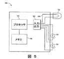
図5は、本発明の原理によるライティングサブシステムを示す。ライティングサブシステム130は、照明信号134に応答する光源132と、図1を参照して記載した送信器および受信器のような送信器136および受信器138を含めてもよい。図3には示していないが、送信器136および光源132は、上記のLEDのような単一のライティングデバイスとして実現してもよい。ライティングサブシステム130は、プロセッサ140、メモリ150および入出力回路160を含んでもよい。
【0079】
送信器136および受信器138は、その上でライティングサブシステム130がデータを送受信することのできる、ライティングネットワークへの物理的リンクを提供することができる。ライティングサブシステム130は、ネットワークを介して伝送されるその他の任意のデータまたは制御信号と共に、イルミネーションデータを受信器138から受け取ってもよい。光源132は、LED灯、プログラマブルLED配列、白熱ランプ、フラッドライト、高圧スポットライト、追跡ライト、蛍光灯、ネオン灯、ハロゲン灯、またはその他の任意の照明光源を含めて、公知の任意の光源でよい。入出力回路160は、任意の適切なアナログ/デジタルおよびデジタル/アナログ回路と、プロセッサ140からの信号を光源132および送信器136用の信号に変換すると共に、受信器138からの信号をプロセッサ140の信号に変換する、その他のシグナルプロセシング回路とを含んでもよい。例えば、入出力回路160は、図3を参照して記載した構成要素を含んでもよい。
【0080】
メモリ150は、ライティングサブシステム132に関係する情報を記憶することができる。例えば、メモリ150は、ライティングサブシステム132の製造日、ライティングサブシステム132の通し番号、ライティングサブシステム132のアドレス、ライティングサブシステムの機能、およびライティングサブシステム132に関する任意の設定または他の情報を記憶してもよい。アドレスは、複数のライティングサブシステム132またはその他のデバイスから、ライティングサブシステム132を固有に特定する、識別子またはデジタル署名となる。次いでこのアドレスを、下記のネットワークのようなライティングネットワーク上を搬送されるデータ用の発送元または宛先アドレスとして使用してもよい。製造月日および通し番号を、例えばライティングサブシステム132、およびライティングサブシステム132の既知の機能を識別するのに使用してもよい。あるいは、上述のように、ライティングサブシステム132の特定の機能を、送信器136を用いて明示的に通信してもよい。
【0081】
設定はメモリ150中に記憶してもよい。これには、ライティングサブシステム132に対応する任意の設定を含んでもよい。例えば、ライティングサブシステム132が、プログラマブルLED配列を含む場合には、この設定には、その配列のプログラミング情報を含めてもよい。この設定には、例えばフェード、タイマーなどの構成可能なライティング効果を含めてもよい。設定には、ライティングサブシステム132用のフラグを含めることによって、他のライティングサブシステム132用の制御ユニットとして作動させるか、または他のライティングサブシステム132用の通信ノードとして作動させるか、あるいは別のデバイスのスレーブとして作動するようにしてもよい。
多数のメモリ装置が公知であり、本発明の原理によるライティングサブシステム132に使用できることが理解されるであろう。例えば、メモリ150は、フラッシュメモリ、リードオンリーメモリ、またはその他の不揮発性メモリでもよく、あるいはメモリは、ランダムアクセスメモリ、ダイナミックランダムアクセスメモリ、または他の揮発性メモリとしてもよい。
【0082】
ライティングサブシステム132には、プロセッサ140を含めてもよい。プロセッサ140は、マイクロプロセッサ、マイクロコントローラ、特定用途向けIC、プログラマブルロジックデバイス、またはライティングサブシステム132の作動を制御するように構成可能な任意の他のデバイスとしてもよい。ライティングサブシステム132がバッテリ電源装置の場合には、プロセッサ140は低電力プロセッサとしてもよい。ライティングサブシステム132のメモリ150には、ライティングサブシステム132のプロセッサ140によって自律的に実行するためのプログラミングコードを含めてもよい。プログラミングコードには、ライティングサブシステム132によってライティングを制御する情報、またはライティングサブシステム132をライティングネットワークの通信ノードとして制御するための情報を含めてもよい。プログラミングコードに、1つまたは複数の診断ルーチンを含めて、ライティングサブシステム132の電源が投入されるたび、または受信器138で受信された制御信号によるなど特に要求されたときに、ライティングサブシステム132の機能を自動的に試験するようにしてもよい。
【0083】
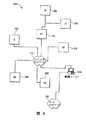
図6は、本発明の原理によるネットワーク化ライティングシステムを示す。ネットワーク化ライティングシステム200には一般に、ライティングネットワーク208上でデータを共有する、複数のライティングサブシステム202、212、214、216、その他のネットワーク化デバイス204、および1つまたは複数の制御ユニット206を含めてもよい。制御ユニット206は、制御ユニット206およびライティングネットワーク208への遠隔アクセスのためのデータネットワーク210に接続してもよい。
ライティングサブシステム202のそれぞれは、図5を参照して前述したもののようなライティングサブシステムでもよい。各ライティングサブシステム202は、ライティングネットワーク208に接続して、他のライティングサブシステム202、他のネットワーク化デバイス204、および制御ユニット206と通信関係を形成してもよい。
【0084】
ライティングサブシステム212の1つが、ライティングネットワーク208内のノードとして動作しているのが示されている。ライティングサブシステム212は、ライティングサブシステム202の1つの構成要素を含む。ライティングサブシステム212は、追加のライティングサブシステム214、216を、ライティングネットワーク208、ならびにそれに接続された制御ユニット206およびネットワーク化デバイス204に接続するノードとして動作するように構成されている。追加のライティングサブシステム214、216は、領域内の照明の全体強度を提供する情報などの制御情報を交換するため、またはそれぞれのライティングサブシステム214、216で利用可能な色彩源を混合することによって照明色を制御する目的で、追加でライティングネットワーク208とは独立に相互に通信するように構成してもよい。
【0085】
次にネットワーク化デバイス204について述べると、各ネットワーク化デバイス204は、ライティングネットワーク208上で通信するための受信器および送信器と共に、前述したプロセッサおよびメモリのようなプロセッサおよびメモリを含んでもよい。ネットワーク化デバイス204は、ライティング取付具、サーモスタット、運動センサ、光センサ、タイマー、スイッチ、電源コントロール、ファン、電子的に動作可能なウインドブラインドおよびカーテン、アラームまたは音響信号生成器、またはその他の任意のセンサ、トランスデューサ、またはライティングネットワーク208と共に動作するアクチュエータを含んでもよい。本発明と共に使用可能なその他のネットワーク化デバイス204としては、煙生成機、オーディオビデオプレゼンテーション装置、ストロボライト、電子ドア、その他がある。
【0086】
本発明の原理によれば、ネットワーク化デバイス204の物理的配置は、ネットワーク化デバイス204が、ライティングネットワーク208に接続された他のデバイスへの有線接続を必要とすることなく、ライティングネットワーク208を介して通信して、センサデータを提供し、かつ/または制御情報を受け取ることのできるようにすることができる。ライティングサブシステム202、212、214、216と同様に、ネットワーク化デバイス204は、ライティングネットワーク208の通信ノードとして動作するか、あるいはスレーブまたは制御構成で動作するように構成してもよい。
【0087】
1つまたは複数のライティングサブシステム202、204、206、210、212、214を独立に動作するように構成し、それぞれが、ライティングネットワーク208を介して、他のライティングサブシステムに、データを送信および/または受信するようにしてもよい。すなわち、ネットワーク208を分散化することにより、例えば、第1のサブネットワーク内の第1のサブグループのライティングサブシステム202、204、206を相互接続すると共に、第2のサブネットワーク内のライティングサブシステム210、212、214の第2のサブグループを副接続する、1つまたは複数のサブネットワークで構成してもよい。ネットワーク208、またはそれに属する任意のサブネットワークは、ある数の自律的ネットワークノード、またはネットワーク208、もしくはそれに属する任意のサブネットワークよって共有されるピア(peer)ネットワークとして動作するように構成してもよい。ピアネットワークまたはクライアントサーバネットワークのいずれかにおいて、1つのノードを、サブネットワークまたはネットワーク208に接続された他のライティングサブシステムの動作を制御するマスタとして動作するようにしてもよい。
【0088】
ネットワーク化ライティングシステム200は、制御ユニット206を含んでもよい。制御ユニット206は、パーソナルコンピュータ、またはユーザ入力を受け取り、ライティングネットワーク208のための制御情報を維持することのできるその他任意のデバイスなどのプログラマブルデバイスとしてもよい。制御ユニット206には、ライティングネットワーク208上での通信を確立するための送信器および受信器を含めてもよい。また、ライティングネットワーク208を管理、監視、制御、およびトラブルシューティングをすると共に、ライティングネットワーク208と整合する他の機能を実行するためのインタフェースを含めて、ライティングネットワーク208の管理用に設計された他の任意のソフトウエアを含めてもよい。例えば、制御ユニット206を用いて、1つまたは複数のライティングサブシステム202またはネットワーク化デバイス204に、制御プログラムをダウンロードして、これらのデバイスおよびサブシステムを自律的に実行するようにしてもよい。または制御ユニット206を使用して、システム200、ならびにネットワーク化デバイス204およびそれに取り付けられたライティングサブシステム202によって提供される環境条件の効果または制御を同期させてもよい。
【0089】
制御ユニット206は、ローカルエリアネットワーク、ワイドエリアネットワーク、プライベートエリアネットワーク、またはインターネットなどの公共ネットワークなどの従来型データネットワーク210に接続してもよい。この接続を介して、ライティングネットワーク208の制御情報を、データネットワーク210に接続した任意のデバイスを介して遠隔地から提供してもよい。さらに、ライティングサブシステム202に関連するセンサ、またはネットワーク化デバイス204からのデータを、簡単な監視機能のため、またはシステム200の対話型制御のために、データネットワーク210に接続された遠隔デバイスから検索して見るようしてもよい。制御ユニット206には、ライティングネットワーク208から利用可能なデータのプライバシーを維持し、ライティングネットワーク208に取り付けられたデバイスを用いた無許可の悪用を防止するために、パスワード保護などの公知のセキュリティ機能を含めて、通信を保護してもよい。
【0090】
ネットワーク化ライティングシステム200は、劇場ライティングシステム、ホームライティングシステム、ウインドディスプレイなどの商業展示、公共施設の屋内ライティングシステム、建築設計または景観設計に設定された屋外ライティングシステム、複数のライティングサブシステム間で有効な情報の通信が可能なその他任意のシステムなどの、任意の制御されたライティング環境において使用できる。例えば、スペクトルセンサを、ネットワーク化デバイス204として設け、それぞれが異なる着色光源を含む、いくつかのライティングサブシステム202からの照明を受けるようにしてもよい。このスペクトルセンサは、ライティングサブシステム202と通信し、所定の色のライティングを自動的に提供することができる。
ネットワーク化ライティングシステム200は、無線コンピュータネットワークなど他の通信ネットワークの代わりに使用してもよい。すなわち、ライティングサブシステムのデータ搬送機能を使用して、ライティング機能とは独立に、コンピュータ間、または通常ネットワーク化される他のデバイス間で、コンピュータの接続ポイント間の物理的ギャップを橋渡しする、データリンクを形成してもよい。
【0091】
図7は、本発明の原理によるモジュール式ライティングサブシステムを示す。モジュール式ライティングサブシステム700には、ある数のモジュール710、712、714、716の汎用プラットフォームを形成するベース702を含めてもよい。ベース702には、LED光源またはその他の光源などの光720を含めてもよい。光720は、レンズなどの離散ライティング領域をベース702内に形成してもよく、またはベース702は、拡散材料(diffusing material)で形成することによって、光720がベース702全体に照明を提供するようにしてもよい。ベース702は、図7には円形に示してあるが、ベース702は任意の形状でよく、またフック、ネジ穴、接着剤、またはある場所に取り付けるためのその他の構成要素を含んでもよい。またベース702には、電気コード、例えば110VAC出力または低圧DC出力に取り付けるためのコードおよびプラグを含めてもよい。
【0092】
各モジュール710、712、714、716は、ベース702内のクレードルに適合し、このクレードルはモジュールを受け入れるように適合された任意の形状のものである。クレードルには、モジュールとの電源接続を形成するための電気接点を含めてもよく、またベース702とモジュール710、712、714、716との間のデータ接続と共に、モジュール710、712、714、716間でのデータ接続を形成するための電気接点を含めてもよい。モジュールには、ライティングサブシステム700の機能を拡張あるいは変更するための構成要素を含めてもよい。例えば、第1のモジュール710に、電力を提供し、かつバッテリまたは外部電源をライティングサブシステム700に適した電源に変換するための変換器を含めてもよい。第2のモジュール712は、赤外線または無線周波数ネットワークへの物理インタフェースなどのネットワークインタフェースや、ライティングサブシステム700とその他のネットワークノードとの間の通信リンクを形成するのに必要な任意のネットワークプロトコルスタックを提供してもよい。
【0093】
第3のモジュール714は、マイクロフォン、温度センサ、デジタルカメラ、または例えば上記の任意のセンサなどのセンサを提供してもよい。第4のモジュール716は、スピーカ、LEDまたはLCDディスプレイ、追加の光源もしくはLED、またはその他の出力デバイスなどの、出力デバイスを提供してもよい。その他のモジュールは、例えばプロセッサまたはその他のデバイスを含んでもよい。一実施態様においては、各クレードルは同一であり、これによって任意のモジュールは任意のクレードルに挿入することができる。この実施態様において、ベース702には、モジュール型式を検出し、各モジュールに適切な接続を形成する回路を含めてもよい。
【0094】
図8は、本発明の原理によるモジュール式ライティングサブシステムのいくつかの実施態様を示す。モジュール式ライティングサブシステム800においては、各モジュール810は、センシングや通信などの追加の機能を提供することができる。図8には、モジュール810は、簡単な機械式および/または電気式接続によってベース820に接続してもよい。接続を形成するのに適切な機構は、当該技術分野において公知であり、それは、セルラー電話およびパーソナルデジタルアシスタントの電源およびデータ接続、電球接続、二重インラインピンパッケージソケット(in−line pin package sockets)、ゼロ挿入力ソケット(zero insertion−force sockets)、ゲームプラットフォームのゲームカートリッジスロット、クレードル、電話およびネットワーク接続用のモジュラージャク、電気ソケット、ゲームプラットフォーム用のゲームカートリッジスロット、コンピュータ用ドッキングステーション、その他である。機械式レベルマウント(mechanical level mounting)または差込みソケット(bayonet mounting)などのロック機構を用いることによって、すべてのモジュール810が、他のモジュールを取り外したり、差し込んだりするときに定位置に留まることを保証することができる。
【0095】
カメラ850などの高バンド幅デバイスへの外部配線840は、図示のようにモジュール810に含めるか、またはベース820内のポートに直接取り付けてもよい。ベース820は、多様なセンシングモジュールおよび通信モジュール810用の中央接続を提供してもよい。図8に概要を示すように、異なる形式および装飾に適合するように、多様な物理的形態を、場違いにならないように製作することができる。機能は、各ベース820について同一とするか、または1つまたは複数の異なる種類のベース820に対して専用化してもよい。
【0096】
図9は、本発明による小売り環境を示す。小売り環境900内で、コンピュータモニタ910は、例えば時間および店内の通行に関する情報を含む情報を、店舗の平面図の有効なグラフィック形式で表示してもよい。平面図920は、グラフ、表形式データ、棒グラフなどを含め、多くの形態をとることができる。一例として、グラフィック表現は、関連するデータを示す、強力で分り易い手段を提供することができる。
【0097】
図9の小売り環境900において、人930は、例えば、2つのディスプレイを見ることができる。それは左側の第1のディスプレイ940および右側の第2のディスプレイ950である。両方のディスプレイ940、950は、注意獲得型の視覚販売手法によって人の注意を惹くことができる。本発明によるライティングネットワークによって、画像認識機能付カメラまたは接近センサなどのセンサを用いて、人を検出して追跡すると共に、ディスプレイ940、950の1方の平面図920上に、人の位置を表示することができる。
【0098】
このようにして、利用客の移動歴を完全にプロットすることができる。一実施態様においては、フロア上のライン960および1つまたは複数の時計970によって、一日の利用客の経路と時間をグラフィックで示すことができる。ライン960の厚さまたは幅が、経路に沿った通行量を示してもよい。時計970は、ディスプレイ940、950で費やされる平均時間を表わしてもよい。このようにして、視覚販売手法を、それぞれの注意獲得能力、通行効率の割合、相互作用について、迅速かつ容易に比較することができる。人930と、ライン960および時計970との関係を示すために、小売り環境900のフロア上に示したが、ライン960および時計970は、店主または管理者が点検するために、コンピュータモニタ910の平面図上に表示することもできる。さらに、顧客の相互作用に関して、ディスプレイ940自体を監視かつ制御してもよい。例えば、ライティングまたは運動デバイスの変更が、顧客を惹き付ける能力について比較、分析することができる。ディスプレイ940自体は、小売り環境900全体の他のセンサを含む、データ収集過程の一部として使用してもよい。
【0099】
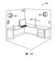
図10は、本発明によるオフィス環境を示す。オフィス環境1000は、家庭であれ職場であれ、ビルディング自動化システムを構築する別の現場を提供する。ライティングモジュールサブシステム1010が、2つの壁に取り付けられているのが示されており、これらはネットワーク化の機能と、人がオフィスにいるかどうかを検出するセンサを提供する。無線および有線ネットワークは、ライティングモジュールサブシステム1010を、入力または出力デバイス、ノードまたは通信ハブとして使用することができる。オフィス環境1000内でライティングモジュールサブシステム1010を使用するシステムは、万引きや従業員の不法侵入を検出できると共に、オフィス使用者に通信路を提供する。ライティングモジュールサブシステム1010はまた、TCP/IPネットワーク化をサポートすると共に、オフィス外部のウエブブラウジング機能を提供することができる。したがってネットワーク化機能は、オフィス環境1000内のデータ収集および報告機能を簡略化し、ネットワークを生成するか、または既存のネットワークを補完することによってオフィスネットワークを簡略化することができる。
【0100】
ポータブルデバイスは、オフィス環境1000への持ち込みおよび持ち出しされると、様々なプロトコルを使用してライティングモジュールサブシステム1010にリンクすることができ、これらのプロトコルは透過的接続または明示的なユーザ制御接続を提供することができる。本明細書に示すと共に詳細を記載した好適な実施態様に関連して、本発明を開示したが、これに対する様々な変更および改良が、当業者であれば容易にわかるであろう。したがって、本発明の趣旨と範囲は、添付の特許請求の範囲によってのみ限定されるものである。
【図面の簡単な説明】
【図1】
本明細書に記載したスマートライティングデバイスを示す図である。
【図2】
本明細書に記載した複数のスマートライティングデバイスを含む、スマートライティングネットワークを示す図である。
【図3】
本発明の原理によるLEDエンコーダおよびLEDデコータを示す図である。
【図4】
本発明の原理による制御信号の構成を示す図である。
【図5】
本発明の原理によるライティングサブシステムを示す図である。
【図6】
本発明の原理によるネットワーク化ライティングシステムを示す図である。
【図7】
本発明の原理によるモジュール化ラティングサブシステムを示す図である。
【図8】
本発明の原理によるモジュール式ライティングサブシステムのいくつかの実施態様を示す図である。
【図9】
本発明による小売り環境を示すである。
【図10】
本発明によるオフィス環境を示す図である。[0001]
Cross-reference of related patents
This application is based, in part, on the following pending US patent application, which claims priority and incorporates the entire disclosure by reference.
US patent application Ser. No. 09 / 425,770.
US Patent Application No. 09/215624
US patent application Ser. No. 09/213537
US patent application Ser. No. 09 / 213,607.
US Patent Application No. 09/213189
US patent application Ser. No. 09 / 213,548.
US Patent Application No. 09/213581
US Patent Application No. 09/213659
US patent application Ser. No. 09 / 213,540.
U.S. Patent Application Serial No. 09/333739
[0002]
Field of the invention
The present invention relates to computer networks and lighting systems. More specifically, the present invention relates to methods of using the former with devices, methods and systems that integrate lighting and data manipulation and transmission functions for lighting and network devices.
[0003]
Background of the Invention
With the advent of computer networks, users have been offered many features not previously available. Distributed users can communicate data using a global network such as a local area network, a wide area network, or the Internet. A software program running on a remote computer can store, process, and retrieve data, including data sent from other locations. That is, a computer network provides the benefits of computer power at each point where data is to be collected, retrieved, or displayed, without requiring a large computer. For these reasons, computer networks have become pervasive in many business environments, such as corporate offices and factories. Computer networks are also located elsewhere, such as in homes and retail environments. However, current computer networks have some significant limitations that prevent their use in new environments, such as retail locations and homes.
[0004]
An important issue in current computer network technology is the need for wiring. Most modern buildings have an excess of wires and cords. It includes computer cables, telephone lines, electrical wiring, speakers, security systems, alarm systems, cable television and modems, and so on. Such complexity leads to various problems. During repair, the appropriate set of wires must be sorted out from each other. Frayed wires can cause short circuits and fires, a problem complicated by the presence of multiple wire systems. New systems are frequently developed and often require new wiring systems. Installing new wiring systems in existing buildings can be expensive. Because such systems are usually located inside walls, their installation is generally intrusive, requiring the demolition and repair of the wall, or wires, pipes, And the complexity involved in slowly and carefully releasing the wire throughout the maze of supports. Accordingly, computer networks that require significant wiring may prevent installation in environments where such wiring is difficult or unsightly (such as a retail environment), or where expertise is not available (such as a home). ing.
[0005]
Another problem with current computer networks is that many of these systems are under the control of, or have the ability to, control a processor, such as a computer. However, these systems are often separate and have individual control systems. This separation makes it more difficult and expensive to update existing systems and install control systems or take advantage of improved new control systems that are available. One system includes components that may be useful for another system, but these systems often remain separate. Accordingly, there is a need to reduce the variety of wiring through walls, ceilings and floors while keeping these different systems under common control to simplify the updating of these systems. An integrated system is not only more efficient, but also allows currently separated systems to achieve significant overall benefits by utilizing components of another system with each other.
[0006]
Another problem with current computer networks is that current wiring techniques make it difficult to place many devices in convenient locations. For example, wiring through telephone outlets typically places networked devices, such as cameras, that require seeing through objects from remote locations without extensive additional wiring in the room where the camera is located. Not suitable for. Therefore, a wiring scheme that provides a more convenient location for networked devices is desired.
Although such a universal system is envisaged, the current proposals are to add new wiring, modify existing wiring, and require high installation costs. Thus, there is a continuing need for universal devices that can provide computer network functionality in a wide range of locations without requiring significant rewiring.
[0007]
Summary of the Invention
The systems and methods described herein relate to a lighting device that includes a lighting component and a microprocessor. In various embodiments, the lighting element includes a light emitting semiconductor, such as a light emitting diode, or other similar device or any of a variety of other lighting elements. The term LED or light-emitting diode should be understood herein to include any light-emitting semiconductor or other lighting element, unless such understanding is excluded. In some embodiments, these devices further include one or more connectors for attaching additional electronic components. In some embodiments, these connections allow for the interchangeable use of modular components on the device. In some embodiments, the lighting device allows communication between the component and the microprocessor, for example, allowing control of the lighting element based on input from a sensor element, or both with other devices. Electronic communication is facilitated by relaying the signal transmission in the opposite direction. In some embodiments, such communication is facilitated by utilizing a network of lighting devices. In some embodiments, the lighting device is interchangeably adapted with conventional lighting elements such as halogen bulbs, Edison-type (screw-in) bulbs, fluorescent lights, and the like.
[0008]
In another embodiment, a system according to the principles of the present invention provides an LED whose output provides fast illumination while providing normal illumination. In one embodiment, the LED brightness is controlled by controlling the duty cycle of the control signal, while independent data can be encoded into the same control signal using a faster modulation scheme. When utilizing LEDs for data communication, the invention, in one embodiment, uses wireless data transmission and reception with networking capabilities to enable the LEDs to communicate with several different devices in the network. These devices include a signal receiver that can decode the data of the optical signal from the LED.
[0009]
The present invention provides a multifunctional lighting device. These devices include a substrate with multiple electrical connections coupled to a power adapter, one or more lighting elements coupled to the electrical connections to emit light, and generate or modulate electrical signals based on external stimuli. Various components are included, such as one or more sensors, and a processor coupled to the electrical connections for processing signals from the sensors.
[0010]
The lighting element can be a light emitting semiconductor, LED, or other lighting element. The processor may be a microprocessor. The sensor may be any sensor that senses any environmental condition ranging from any electromagnetic signal to an acoustic, biological or chemical signal, and other signals. Examples include IR detectors, cameras, motion detectors, ozone detectors, carbon monoxide detectors, other chemical detectors, proximity detectors, photovoltaic sensors, photoconductive sensors, photodiodes, phototransistors, There are a photoemission sensor, a photoelectric sensor, a microwave receiver, a UV sensor, a magnetic sensor, a magnetoresistive sensor, and a position sensor.
[0011]
The sensor may sense temperature. The sensors may be, for example, thermocouples, thermistors, radiation pyrometers, radiation thermometers, fiber optic temperature sensors, semiconductor temperature sensors, and resistance temperature detectors. The sensor may sense sound, for example, a microphone, a piezoelectric material, or an ultrasonic sensor. The sensor may sense vibration, humidity, or the concentration of steam, particulate matter, or gas.
[0012]
In some implementations, the device may include a data connection for coupling the processor to a data network, or a communication connection between the sensor and the processor for transmitting signals from the sensor to the processor.
The invention also provides a substrate mounting a plurality of electrical connections coupled to a power adapter, a lighting element coupled to the electrical connections for emitting light, a signal unit for emitting signals, and coupled to the electrical connections. A multi-functional lighting device, which can include a processor for instructing the signal unit to emit a signal.
[0013]
The present invention also provides a method for receiving data. The method includes providing a substrate carrying a plurality of electrical connections coupled to a power adapter, providing a lighting element coupled to the electrical connections, providing a sensor, coupled to the electrical connections and the sensor. Includes various steps such as providing a processor, receiving a stimulus at the sensor, transmitting a signal representative of the stimulus from the sensor to the processor. In some embodiments, the method includes sending instructions to the actuator to change the position of the lighting element.
[0014]
The present invention also provides a method for transmitting data. The method provides a substrate carrying a plurality of electrical connections coupled to a power adapter, a lighting element coupled to the electrical connections, a signal unit for emitting signals, a processor coupled to the electrical connections and the signal units, respectively. And transmitting a signal command from the processor to the signal unit.
[0015]
The invention also relates to a method of manufacturing a multifunctional lighting device, for example providing a substrate carrying a plurality of electrical connections coupled to a power adapter, coupling a lighting element to the electrical connections, A method is provided that includes various steps such as coupling to a connection, coupling a sensor to an electrical connection and a processor. The method comprises the steps of combining sensors, such as an IR detector, a camera, a motion detector, a proximity detector, a photovoltaic sensor, a photoconductive sensor, a photodiode, a phototransistor, a photoemission sensor, a magneto-optical sensor, a microwave. Combining a sensor selected from a receiver, a UV sensor, a magnetic sensor, a magnetoresistive sensor, and a position sensor, or a thermocouple, a thermistor, a radiation pyrometer, a radiation thermometer, a fiber optic temperature sensor, a semiconductor temperature sensor, and Combining a sensor selected from a resistance temperature detector may be included. The coupling of the sensors may include the coupling of a sensor that senses sound.
[0016]
The method of manufacturing a multifunctional lighting device provided by the present invention also includes providing a substrate carrying a plurality of electrical connections coupled to a power adapter, coupling the lighting element to the electrical connections, and coupling the processor to the electrical connections. And coupling the signal unit to the electrical connection and the processor.
[0017]
SUMMARY OF THE INVENTION The present invention is a method of manufacturing a multi-functional lighting device, comprising: providing a substrate carrying a plurality of electrical connections coupled to a power adapter; coupling a lighting element to the electrical connections; A method is provided that includes coupling and coupling the processor to electrical connections and actuators.
The present invention is also a method of constructing a network of multifunctional lighting devices, comprising the steps of arranging a plurality of lighting devices in one arrangement according to the present disclosure, and providing a method for connecting between each lighting device and another lighting device. Establishing a communication link.
[0018]
The present invention is various methods of executing a business, providing a retail environment, writing the retail environment using a lighting system including a lighting element and a microprocessor, and detecting a condition of the retail environment. A method comprising: adjusting lighting in a retail environment to reflect a sensed condition. The condition detected is the approach of the customer to the retail item, in which case the lighting conditions may be adjusted to increase the illumination of the retail item. The detected state may be a customer's approach to the store entrance, in which case the lighting conditions may be adjusted to motivate the customer to go further into the store. The lighting condition may be a moving rainbow effect.
The figures shown below show several embodiments for illustrating the invention, in which the same reference numbers indicate the same elements. It should be understood that these embodiments are illustrative of the invention and are not limiting in any way. BRIEF DESCRIPTION OF THE DRAWINGS The invention will be more completely understood from the following further description, with reference to the accompanying drawings, in which: FIG.
[0019]
Detailed Description of the Illustrated Embodiment
The following description relates to several embodiments that illustrate the invention. Various modifications of the present invention will occur to those skilled in the art, and such modifications and improvements are intended to be within the scope of the disclosure. Accordingly, the scope of the present invention is not in any way limited to the following disclosure.
The systems and methods described herein relate to an electronic device, such as
[0020]
[0021]
[0022]
[0023]
[0024]
In some embodiments,
[0025]
Examples of components that can be used as emitters include those that emit electromagnetic radiation (such as infrared, microwave, wireless, or other types of signals), acoustic signals (such as speakers, ultrasonic emitters, or other sound waves). Other devices that emit signals, or emit signals, especially communication signals. An actuator capable of generating a force in response to an electronic signal is also coupled to the
[0026]
A plurality of
[0027]
The techniques and systems described in U.S. Patent Nos. 5,844,888, 5,113,498, and 4,969,146 can be adapted for use in the lighting networks described herein. Therefore, for example, the
[0028]
The smart lighting element may be used for any of a wide range of functions. The examples shown below are exemplary uses possible in a building such as a home or office, for example, where a ceiling light fixture includes a smart lighting element as described herein. Additionally or alternatively, the smart lighting device can be used in displays, lit floors or wall panels, cover lighting, or any other desired configuration. Other configurations and uses of the smart lighting element having the following or other features are considered to be within the scope of the invention.
[0029]
In one embodiment, a smart lighting network can be used to facilitate mobile communication technology. Cellular telephones, wireless data transmissions (such as Apple Computer's Airpoint technology), and other mobile communication devices generally require high energy transmission or proximity receivers to connect to the appropriate network. For example, in a building with a smart lighting network connected to the Internet or a telephone network, each room may be composed of smart lighting devices, including infrared, wireless, microwave or other suitable transceivers. By using traffic management techniques currently used in high-density networks or mobile telephony, for example, one or more cordless telephones can operate in buildings with low power signals, thereby providing battery power Can be reduced.
[0030]
This technology can also be used for radiotelephones, with specific applications, such as third generation radiotelephone solutions that enable microcells in cellular infrastructure. By using such a solution, a microcell can be formed inside a building and connected to an external wireless network via a smart lighting network or directly to the PSTN. Such a solution can save wireless device energy that would otherwise be required to transmit signals through building walls.
[0031]
Similarly, portable computers can remain connected to the Internet or other data networks while traveling throughout a building. For example, the signal from a remote switch for a television or stereo system is received in one room, transferred over a smart lighting network, and transmitted to the room containing the corresponding components (or over the entire network), thereby increasing the scope of the remote control. For example, it is possible to control a stereo system from any room in a house. Even in situations where there is no movement, such networks may open and simplify the common communication system by reducing the number of cords and wires required to maintain connectivity. For example, a desk can be located anywhere in the office, regardless of the location of the data or telephone jack.
[0032]
Computer components can communicate through space rather than on wires, making components such as monitors, computers, printers, etc. difficult or impossible using wired connections. In a manner, they can be configured or rearranged. For example, it is possible to move a printer to another room in the office, even while data is being transferred from the computer to the printer, without rewiring to make the connection. Thus, the methods and systems disclosed herein may provide a wireless scheme as an alternative to structured wiring for various functions.
[0033]
In another embodiment, a smart lighting network may be used to deliver audiovisual signals. For example, the network may include devices with or with built-in speakers and processor-controlled lighting elements. When a user initiates playback of a recorded audio or audiovisual program, or receives an audio or audiovisual transmission such as a radio or television broadcast, the smart lighting network may generate the audio portion of the transmission or recording. It may be. Surround sound technology or other spatial acoustic imaging techniques may be used to create a multi-channel surround sound effect, which may be mediated by a central controller or by individual processors of a smart lighting device. The remote components may communicate via a smart lighting network. For example, a satellite speaker of a surround sound system can receive an audio signal wirelessly via a smart lighting network.
[0034]
If the program includes a lighting track that complements the conventional audiovisual data and provides an indication of the ambient light status, the lighting elements of the smart lighting network can be used to create a lighting effect in conjunction with the conventional audiovisual program. Can be generated. For example, conventional television or cinema using lightning, sunsets, fire red glows, or other effects that can be created by modifying the color and / or brightness of environmental lighting The effect of the experience can be emphasized. Similarly, audio feeds, such as music or intercom applications, can be broadcast to the entire smart lighting network or sent to specific lighting elements within the network without the need for a separate system wired throughout the building. You can also. Conversely, by modifying or adapting an existing lighting, intercom, or speaker system, a smart lighting system can be provided without requiring extensive rewriting or destructive updates.
[0035]
Similar smart lighting networks can be used in theaters, music halls, auditoriums, or other venues. For example, a smart lighting network can be provided on the stage, including lighting elements, microphones, and sensors for tracking movement of performers, actors, and the like. Such a system allows a smart lighting network to program a lighting scene designed for a particular play, opera, musical or other theater event. The network can monitor the progress of the event, for example by tracking the location and / or movement of actors, etc., and change the lighting between scenes, for example, or program to match events on stage, for example. It can provide effects such as lightning, deepening sunsets, sunrises, power outages (including light control and temporary flickering, etc.).
[0036]
Further, such a lighting system may include a smart lighting element located in a seating area, for example, above the audience. These lighting elements may also include a microphone for reproducing sound from a stage or a performance area, including pre-recorded sound effects. Pre-recorded sound effects such as lightning, car horns, phone sounds, tire squeals, brake squeals, etc., are designed for events by sensor inputs from smart lighting elements on the stage, similar to the lighting effects described above. You can also trigger according to the program you have set. Further, the lighting elements in the seating area can reproduce on-stage lighting effects across the entire audience, for example, to simulate a flashing light of a fire, a flash of lightning, dawn, or other lighting effects.
[0037]
By including a microphone and speakers in the smart lighting network, communication can be set up without the need for a separate telephone device. For example, a smart lighting device may operate as a voice-driven phone, dialing a number or contacting a party with voice commands. The communication partner is thus released from the hand-held phone device and is available to a larger number of participants in a larger area than, for example, usually with a speakerphone. In addition, cameras can be included in smart lighting networks to enable videophone applications. In some embodiments, the smart lighting system is configured to activate the camera in the nearest smart lighting device in response to the voice and, optionally, use the actuator to direct the camera to the speaker be able to. The smart lighting network can be configured to locate speaker input or other auditory input by triangulation or other means. The methods and systems disclosed herein can be used as methods such as a system for locating objects in a room.
[0038]
By providing an appropriately positioned light sensor, a smart lighting device can detect ambient light and modify the output of the lighting element to achieve a predetermined brightness or color. Such networks are particularly suitable for sensitive environments such as operating rooms, photo studios, or agricultural work. In an agricultural environment, smart lighting devices may include sensors such as humidity sensors or temperature sensors, thereby coordinating lighting with other systems such as computer-controlled humidification, heating, irrigation, watering systems, etc. It is possible to control and maintain optimal growth conditions.
[0039]
The smart lighting device may provide an integrated sensor / alarm system in a home, business, or vehicle, for example, by providing chemical sensors that detect smoke, carbon monoxide, radon, gas leaks, and the like. Vibration sensors can be used for earthquake monitoring. The proximity and / or motion detector can be used in a security system, optionally in combination with a camera component. Such a network can be used to monitor children and transmit data over a network, such as another room or the Internet, for example, using a microphone and / or camera operating in the baby's room. Speakers and / or lights can be used to generate an alarm or warning signal when a specified stimulus is detected. By accessing such smart lighting networks over larger networks, such as the Internet, security companies can control building lighting and other features remotely, making them more effective than simple lighting timers. Robbery can be controlled in a controlled manner, as well as remote video surveillance for security purposes or to distinguish false alarms from genuine dangers.
[0040]
Additional data collection and monitoring functions can be achieved by the smart lighting network. For example, smart lighting elements can be placed in public places, such as retail stores, conference halls, city areas, sports venues, entertainment venues, and the like, to monitor the flow of people, vehicles, and other objects. The smart lighting element can measure, for example, the number of people or objects passing by the unit, the speed at which the person or object passes by the unit, or other suitable measurements. The collected data is then used to analyze traffic flow, traffic patterns, traffic congestion points, etc., for example, by using a processor connected to a smart lighting network or by downloading and analyzing the collected information to a suitable processor or the like. Can be measured. This analysis can be used, for example, to identify traffic congestion points or change traffic flow, to identify changes in arrangement or configuration that have the effect of mitigating passage and congestion, or to e.g. Or how to find a seat in a theater.
[0041]
In retail or entertainment environments, such as department stores, parks, resorts, casinos, and the like, such data is useful in identifying customer reactions to exhibits. For example, a smart lighting element within an exhibit, or a smart lighting network at a retail facility, may collect information about the average time a customer views the exhibit, whether the exhibit attracts customer attention from a remote location in the store, or By capturing and analyzing features, such as facial expressions, the customer's interest and response to retail displays, promotions, or other displays to attract attention can be measured. Such information can be further correlated with sales data, such as information collected at checkout lines, cash registers, or other inventory systems, to measure the overall efficiency of retail exhibits and promotions. By investigating and analyzing such data, retailers and marketers can see what types of exhibits, where, and what combinations of products are favored by customers, leading to increased sales. Can be accurately assessed as promising and most effective. Such information can be used to place products of interest throughout the store to achieve uniform traffic and increase customer exposure to new or unknown products, or products that are usually purchased on an impulse basis. You can make it.
[0042]
Various tracking functions can be easily achieved by using a smart lighting network. For example, an object that is within the measurement range of a sensor provided on a smart lighting element such as a camera, microphone, motion detector, etc., is identified as an object by the unit or network. When the object passes out of range, the network tracks the movement of the object, determines where the object is going, identifies the smart lighting element at that location, and places the object in the measurement range of the second smart lighting element. Ingress is tracked by handoff techniques or other protocols.
[0043]
Smart lighting networks can be used for various entertainment applications. For example, a theater or other lighting system can be quickly set up in an outdoor environment, or an indoor environment that is not wired for a complex lighting system. Suitable smart lighting devices can be controlled by wireless commands, for example, instead of being placed near an electrical outlet and wired together. Such networks can also function as sound systems by incorporating speakers within the smart lighting element. A modular network that works with minimal wiring can be used to set up mobile performances or to install complex wiring arrangements such as high school gymnasiums, stone churches, tents, outdoor gatherings, fountains or other water displays. Facilitates installation in unsightly, dangerous or difficult environments. In addition, smart lighting devices are microphones and proximity sensors that can be used to interactively modulate audiovisual output, such as in response to the approach of dancers or spectators, or in response to the speed or strength of music. And the like. Responsive or interactive smart lighting devices can also be used in fun houses or other interactive environments for entertainment purposes.
[0044]
The smart lighting network may be controlled by a centralized system or cooperatively by the collective microprocessor of the smart lighting network. Equipment and home, office, industrial, or other devices may be mounted for remote control, e.g., by infrared, microwave, or wireless signals, and controlled by a centralized system using a smart lighting network. Good. Such a system can be used to automate building system functions and electrical equipment, for example, without requiring extensive or specific rewiring. Use is widespread, e.g. starting a coffee machine, turning on a computer, increasing thermostat settings, starting and warming up a car at designated times, or continuously controlling key functions of a processing plant. Can be used to control Including sensors in the system allows for more complex and interactive functions, such as turning on a light when a person enters a room and turning it off when the room is empty.
[0045]
By wearing badges that transmit signals based on identification or general classification, the system can control entry and exit to various parts of the building, and music that matches the occupant's predetermined preferences. Can be played indoors, the activity and location of the occupants of the building can be monitored, and other functions can be performed. Voice commands may be received, interpreted, and executed at remote locations in the building, optionally depending on the status of the originator of the command as determined by identification, such as by badge, voice or facial recognition. Because the network is accessible from a telecommunications network, such as the Internet or a public telephone network, the environment of a smart lighting network can be monitored and / or modified from a remote location. By receiving outputs from sensors in the smart lighting network, for example, business status, home security status, and other status may be verified at a remote terminal, for example, using a web browser or other suitable interface. Good. The instructions can also be sent from a remote location, allowing the smart lighting network to adjust any function such as building temperature, lighting control, equipment or machine operation that is controlled or regulated.
[0046]
Further, those skilled in the art will recognize that a smart lighting network can include, for example, a network by including smart lighting elements and smart units that do not include a lighting element but include other functions such as sensors, transmitters, indicators, speakers, and the like. It will be appreciated that connectivity can be gathered or transmitted in an environment where lighting is desired but lighting is not required or desired.
The following description will be understood by those skilled in the art as various embodiments that illustrate the invention without limiting the scope or characteristics of the invention in any way. As will be apparent from the following, the digital lighting system of the smart lighting element supports the collection, exchange and description of sensor information available throughout the network, as well as the application of sensor information to control and modify the environment Can work as a platform.
[0047]
Digital lighting networks are useful in retail environments. Basically, retail stores and chains seek to attract people and spend more on products and services. An observer can be used to observe the shopper, and to extract trends, responses, and other valuable information from the observations. The smart lighting network enhanced by the sensing device provides the same observing ability to automatically generate detailed customer reports. The information you get may be continuous monitoring of the entire store, elucidating traffic, providing feedback on product sales, analyzing product placement trials, placement, writing, sales promotion, graphics, It can be used to analyze the effects of store facilities and the like. Such knowledge is usually not easily grasped and is valuable to store or chain owners.
[0048]
More significant than simply tracking and providing data collection is the possibility of immediate feedback of user behavior. Thus, retailers can receive immediate or pseudo-immediate data about shoppers' responses to various exhibits and product placements. This information may be used to create subtle or prominent, dynamic displays, such as changing display lighting in response to shoppers stopping in front of the display, or activating an acoustic track. . Real-time shopping information can be used to control inventory more closely and track sales trends.
[0049]
Supermarkets and other low-profit retailers can take advantage of digital lighting networks to provide better communication and access to merchandise, and more accurately price shelf space for suppliers and wholesalers. can do. Supplier and wholesalers may have already paid for shelf space and location, but find that tracking information is very useful in predicting how people will move in stores. Will find out. Stores with smart lighting networks can provide such information to major wholesalers free of charge and benefit stores, suppliers, and customers.
[0050]
Information collected in retail applications may be presented at a central location, such as a computer, and may include software that controls various outputs in a digital lighting network, such as acoustic systems, lights, and other devices. .
The digital lighting network of smart lighting elements can be effectively used for security systems. Many public buildings, architectural lobbies, stairs, elevators, convenience stores, bank ATMs, and many streets are equipped with cameras that observe people walking in connection with their business. Extending such tracking capabilities to the physical world using smart lighting networks, much like portals and websites provide user click tracking, allows brick and mortar systems to And be able to track behavior.
[0051]
For high crime areas, smart lighting networks can be used to track vehicles and people to help arrest current or subsequent offenders. A smart lighting element can pass information such that tracking establishes continuity of data and information between multiple network units. For example, in a field of view, a vehicle is labeled as a target object, then travels, and then passed to an adjacent node as an object. This technique establishes continuity and consistency for automating the tracking process as if the area were within one large camera.
[0052]
These scenarios, and others that incorporate proximity, chemical sensing, smoke and fire detectors, can be facilitated by the ability to adapt and change the functionality of smart lighting elements in a modular fashion. Also, the security system can be quickly adapted to changing conditions.
The digital lighting network of smart lighting components can be effectively used in offices or other commercial areas. Smart lighting networks that utilize wireless technology can be easily extended and adapted as businesses grow and scale, and can be offered as an alternative or enhancement to wireless local area networks in commercial environments . Local radio enables network access throughout a building or enterprise premises, and greatly enhances the ability to transfer and access information.
[0053]
The digital lighting network of smart lighting components can be used effectively for theme parks, resorts, hotels, casinos and entertainment companies, all of which require meticulous and continuous customer tracking. Smart lighting networks can quickly identify areas where people can avoid or be attracted.
At trade shows and other large events, smart lighting networks can be used to measure visitor flow, interest, dwell time, and interactions at individual booths or across the entire area of the trade fair. Theaters naturally understand ticket sales, but using a smart lighting network will show how people enter and exit the theater, how they prefer to sit and move, and how Can get more information as to whether they offer access and sales. Large cinemas are always dealing with scheduling and audience control problems, and using a smart lighting network can diagnose and monitor problems and predict the effectiveness of solutions.
[0054]
In some embodiments, the hardware and network of the digital lighting network can utilize readily available standardized technology as a smart lighting element. Reduce installation costs by using existing power wiring and using new wireless standards, such as 802.11 wireless LAN standards, Bluetooth, or infrared data communication standards organization (IrDA) standards. Can be.
In one embodiment, the smart lighting element is fully modular. Each smart lighting element is a modular I / O and network device that can be added to or removed from the digital lighting network seamlessly. The use of an open architecture allows the use and evolution of a variety of different smart lighting elements, and other compatible devices for different applications. The framework includes, for each smart lighting element or other device (collectively referred to as modules), a conduit to power and wired networks and a minimal set of I / O functions. Both elements can be designed to make adding and changing modules simple and efficient, depending on the desired feature set.
[0055]
Control the module with software that enables point-and-click based operation, such as general data collection and a browser interface, as well as more detailed functional definitions and controls for specific modules known to the software. Is also good. For example, the software may include a graphic interface that displays information generated by one or more modules, allowing light intensity or color control for modules known to be smart lighting elements. .
[0056]
Maps can provide an intuitive user interface that displays rooms and regions. For example, a store map can be displayed, and modules can be arranged in the map by a drag / drop operation. Then, by double-clicking the module, a configuration window or menu is opened, and if the configuration is online, the function of the module can be queried. This may open a different window or frame listing the features and the results of the self-test. If the function or type of the module is known in advance, it can be entered directly into the configuration window or selected as a drag-and-drop item on the area map. Since the module can include output devices (speakers, lights, mobile systems, etc.), the program or action can be written or developed via control software or independently to the module on a digital lighting network. Can be incorporated.
[0057]
Such a smart lighting network allows data and actions to be linked. The graphical user interface may include tools for generating a process flow. For example, various processes, such as deterministic processes, event-driven processes, and the implementation of conditional logic, may be described graphically by simple block or state diagram techniques. For example, when someone enters a room, the lighting sequence can be triggered, or multiple actions can be triggered by a single "presentation" switch.
[0058]
Digital lighting networks can be used effectively as data acquisition tools. Data collection can be automated to monitor traffic flow in corridors, open areas, elevators, and doorways, and traffic flow can be related to time, location, or other factors.
An example of an application in a retail environment will now be described in detail. Clothing chains that serve teen women in malls throughout the Northeast United States can install modules with a variety of sensor devices, including cameras and proximity detectors, and digital lighting. Each of these modules can be installed with a single power connection, and one of the modules can be connected to the store's data network using a telephone line for data communication with the store's headquarters. The system may also be connected to a point-of-sale (POS) data collection system to enable exchange and integration of the acquired data.
[0059]
After opening the store in the morning, the store manager can look at the monitor screen and explore all activities on the digital network at night. The system may signal that a cleaner has entered. However, the system may also warn that the air conditioning has failed at night and that the temperature sensor has detected a significant temperature rise between 3 and 4 am. For clothing, this is not a major problem, but some cosmetics in stores may be adversely affected by elevated temperatures.
[0060]
As the customer moves through the store during the day, the general movement can be tracked. Thereafter, a map can be generated from the day's data collection to display human traffic and dwell times at various points in the store. This information may reveal, for example, that shirt and accessory corridors are the least visited in stores. The hallway is easy to access, but managers may find that clothing racks inadvertently made the hallway invisible as customers approached the area .
[0061]
Daily receipts can also reveal intriguing anomalies. For example, clustering of data that can be used to provide insight into buying behavior may indicate that a girl who buys small pants and shirts also buys a much larger shirt that does not match the size of the pants. The manager can move these products closer together in the store and see if this increases sales and traffic in that area.
Rapid tracking analysis reveals that people do not stop in front of the entrance display, but rather pass through the entrance to the store, and now either move the entrance display further into the store or make the entrance display lively May be encouraged. Traffic near the blouse corridor may be confirmed to be normal, even when sales are significantly lower than normal. This information may indicate that one or both are passing quickly if more than one person is in the area. After the investigation, the manager may notice that the display cases have been moved too close to a comfortable distance for the two people, and may move the display items apart from each other.
[0062]
Some garment suppliers may purchase data from several stores for analysis. These merchants may investigate traffic trends and their product locations within the store. A better placement could result in better sales. In this way, the module facilitates measuring the efficiency of the exhibition area.
A customer may enter and view a product display showing clothing representative items, such as pants, skirts, blouses, shirts, lingerie, and the like. When a customer touches a point of clothing, a smooth but rapid sequence of lights may follow the path of the store ceiling and indicate where such goods are being displayed. This light may end up as a single indicator light on the indicated garment. This allows the customer to move to the designated location and view the sweater exhibit.
[0063]
Price changes can be dynamically transferred via the smart lighting network. For example, where the customer spends a long time in front of the exhibit, the price of the product may be reduced and the customer may be invited to purchase. Further, the price for a customer can be personalized by tracking the customer to the checkout and providing the customer with the price displayed when the customer selected the item. Alternatively, the price may be increased if, for example, 50% of the inventory is sold in the morning of the day. More complex pricing schemes may be implemented and individual customers may be personalized according to their observed shopping behavior.
[0064]
In a retail environment like the one described above, information about products, product sales, customers, inventory, prices, etc. is the intellectual property of store owners and managers, and may be of high value. It may be desirable to add Secure transmission can be implemented using several encryption techniques or other techniques, for example, as a physical layer, network layer, or application layer encryption system, for each smart lighting network node. It can be implemented depending on complexity and processing power. Further, security may be negotiated individually for each communication link, or each smart lighting element may have its own encryption key, or a single key may be provided for the entire smart lighting network.
[0065]
Next, the application of the digital lighting system including the smart lighting element to an arena environment will be described in detail. Sports stadiums may house rock concerts along with sporting events such as hockey and basketball. These events can bring together a completely different kind of audience who behaves differently. For security, existing CCTV camera systems may have been suitable, but they do not help track the pre-, ongoing and post-event traffic flow. However, the module facilitates tracking of traffic flow during the event. For example, a smart lighting network can provide a detailed map of the traffic flow that allows the doorways to be easily reconfigured and redesigned. In addition, the system can identify some point-of-sale and washroom configurations that have become significant obstacles during a particular event. Problems can be reduced or eliminated by closing some booths and opening others.
[0066]
Furthermore, during a rock concert, a group of wandering fans can cause serious damage or damage to others. The tracking capabilities and sensing devices of the smart lighting network identify and track the culprit, allowing security personnel to have sufficient time to plan and execute the containment.
In some embodiments of the present invention, the modulation of the LEDs of the smart lighting devices disclosed herein provides communication between smart lighting devices or between a smart lighting device and another networked device.
[0067]
Recent developments in LED-based general-purpose lighting fixtures include the use of lighting that mixes monochromatic red, green, and blue LEDs and other fixed wavelength LEDs, or uses blue LEDs to generate a color spectrum. And so on. Such an LED system is disclosed in U.S. patent application Ser. No. 09 / 215,624 filed Dec. 17, 1998, which is incorporated herein by reference. Generally, the LEDs in these systems are configured as saturating devices, i.e., have a single "on" intensity that depends on the trim current. The perceived intensity of the LED in these systems is controlled by rapidly switching the LED on and off by a control signal having n adjusted duty cycles. Although the period of this control signal is short enough that the human eye cannot detect the progress of the "on" and "off" states, conventional LEDs still leave a significant extra switching speed. ing.
[0068]
In wireless communication, a data signal is modulated onto a carrier signal, such as a radio frequency, visible light (laser), or infrared carrier, using an appropriate modulation scheme selected according to the transmission medium. For wireless data transmission, white infrared LEDs are typically used using pulse code modulation "PCM" and visible light LEDs have been used for illumination. In the field of lighting, LEDs provide great design flexibility because by mixing LEDs of different wavelengths, ie different colors, the desired lighting effect and the desired color can be produced. A significant disadvantage is that systems of LEDs, and more specifically, visible light LEDs, require additional, independent data communication hardware to operate as a networked lighting system. This includes twisted-pair wire leads, or other bus structures, which must physically interconnect one or more control units to the lighting subsystem to be controlled.
[0069]
In this embodiment, an LED system is provided that controls illumination intensity using pulse width modulation (PCM) and carries data using pulse code modulation (PCM). However, those skilled in the art will appreciate that the methods and systems described herein can be suitably adapted to other LED-appropriate modulation schemes and further used in conjunction with many known data network techniques. You will understand what you can do. The principles of the present invention are particularly applicable to any environment where dual functions of lighting and wireless data communication are desired.
[0070]
FIG. 3 illustrates an LED encoder and LED decoder according to the principles of the present invention. It will be appreciated that multiple LEDs and decoders can be used in combination as described in more detail below. The single LED system includes an
[0071]
In a conventional LED system, the illumination signal applied to the
[0072]
It will be appreciated that many devices for receiving, processing and generating signals are known and can be used in the present invention.
[0073]
In one embodiment,
[0074]
FIG. 4 shows a structure of a control signal according to the principle of the present invention. The control signals of FIG. 4 are particularly applicable to environments where it is desired to control lighting and transmit data within a shared optical channel. As shown, the
[0075]
The
[0076]
The visible light from the
[0077]
As another technique, a lighting function and a data communication function can be combined. For example, a data signal may be transmitted by an infrared LED and an illumination signal may be transmitted by a visible LED. In one embodiment, by providing a matching light filter on the receiver, data can be transmitted using only specific colors of visible light LEDs. In another embodiment, the data may be transmitted at some time before illumination. The data signal and the illumination signal alternate in a fixed period, or the data is transmitted only during the power-up phase, or a modulated data header precedes the data, signaling the receiver that the data will follow. Good. In another embodiment, the lighting is provided by any conventional light source, such as an incandescent or fluorescent light, while data can be transmitted using a modulated LED. Any of these or other techniques may be used to implement a networked lighting system.
[0078]
FIG. 5 illustrates a lighting subsystem according to the principles of the present invention. The
[0079]
[0080]
The
[0081]
The settings may be stored in the
It will be appreciated that many memory devices are known and can be used in the
[0082]
The
[0083]
FIG. 6 illustrates a networked lighting system according to the principles of the present invention.
Each of the
[0084]
One of the
[0085]
Turning now to the
[0086]
In accordance with the principles of the present invention, the physical placement of the
[0087]
One or
[0088]
[0089]
The
[0090]
The
[0091]
FIG. 7 illustrates a modular lighting subsystem according to the principles of the present invention. The
[0092]
Each
[0093]
The third module 714 may provide a microphone, a temperature sensor, a digital camera, or a sensor such as, for example, any of the sensors described above. The
[0094]
FIG. 8 illustrates some embodiments of a modular lighting subsystem according to the principles of the present invention. In the
[0095]
[0096]
FIG. 9 illustrates a retail environment according to the present invention. Within the
[0097]
In the
[0098]
In this way, the travel history of the customer can be completely plotted. In one embodiment, a
[0099]
FIG. 10 illustrates an office environment according to the present invention. Office environment 1000 provides another site for building a building automation system, whether at home or at work. The
[0100]
As the portable device is brought into and out of the office environment 1000, it can be linked to the
[Brief description of the drawings]
FIG.
FIG. 2 illustrates a smart lighting device as described herein.
FIG. 2
FIG. 2 illustrates a smart lighting network including a plurality of smart lighting devices described herein.
FIG. 3
FIG. 4 illustrates an LED encoder and LED decoder according to the principles of the present invention.
FIG. 4
FIG. 4 is a diagram illustrating a configuration of a control signal according to the principle of the present invention.
FIG. 5
FIG. 2 illustrates a lighting subsystem according to the principles of the present invention.
FIG. 6
FIG. 1 illustrates a networked lighting system according to the principles of the present invention.
FIG. 7
FIG. 2 illustrates a modular rating subsystem according to the principles of the present invention.
FIG. 8
FIG. 4 illustrates some embodiments of a modular lighting subsystem in accordance with the principles of the present invention.
FIG. 9
3 illustrates a retail environment according to the present invention.
FIG. 10
FIG. 2 illustrates an office environment according to the present invention.
Claims (143)
Translated fromJapaneseプラットフォームを提供するステップと、
プラットフォーム上に、ライティング機能を有すると共に、少なくとも1つの非ライティング機能をを配置するステップと、
ライティング機能および非ライティング機能を提供するためのライティング要素を制御するための少なくとも1つのプロセッサを提供するステップと、
ライティング機能を制御するためのパルス幅変調信号を生成するステップとを含む方法。A method for providing multi-function in a multi-function device, comprising:
Providing a platform;
Having a lighting function and arranging at least one non-lighting function on the platform;
Providing at least one processor for controlling a lighting element for providing lighting and non-lighting functions;
Generating a pulse width modulated signal for controlling a lighting function.
プラットフォーム上に配置されて、ライティング機能を有する第1の要素と、
プラットフォーム上に配置されて、非ライティング機能を有する第2の要素と、
第1および第2を制御するための少なくとも1つのプロセッサとを含み、プロセッサが、ライティング機能を制御するためにパルス幅変調信号を生成する、多機能デバイス。Platform and
A first element disposed on the platform and having a lighting function;
A second element disposed on the platform and having a non-lighting function;
At least one processor for controlling the first and second, wherein the processor generates a pulse width modulated signal for controlling a lighting function.
プラットフォームを提供するステップと、
ライティング機能を有する第1の要素を、プラットフォーム上に配置するステップと、
非ライティング機能を有する第2のライティング要素を、プラットフォーム上に配置するステップと、
第1、第2および第3の要素を制御するためのプロセッサを提供するステップとを含み、プロセッサがライティング機能を制御するためにパルス幅変調信号を生成する前記方法。A method for providing multiple functions by a lighting device,
Providing a platform;
Placing a first element having a lighting function on a platform;
Placing a second lighting element with non-lighting functionality on the platform;
Providing a processor for controlling the first, second, and third elements, wherein the processor generates a pulse width modulated signal to control a lighting function.
モバイルデバイスの接近を検出するための検出器と、
モバイルデバイスの接近に応答してディスプレイの照明を変更するプロセッサとを含む、照明システム。A lighting element for illuminating the display,
A detector for detecting approach of a mobile device;
A processor that changes lighting of the display in response to the approach of the mobile device.
モバイルデバイスの接近を検出するための検知器を提供するステップと、
モバイルデバイスの接近に応答して、ディスプレイの照明を変更するためのプロセッサを提供するステップとを含む、照明を提供する方法。Providing a lighting element for illuminating the display;
Providing a detector for detecting the proximity of the mobile device;
Providing a processor for changing the illumination of the display in response to the approach of the mobile device.
プラットフォーム上に配置されて、ライティング機能を有する第1の要素と、
プラットフォーム上に配置されて、非ライティング機能を有する第2の要素と、
プラットフォーム上に配置されて、第2の要素の機能と異なる非ライティング機能を有する第3の要素と、
第1、第2、および第3の要素を制御するための少なくとも1つのプロセッサとを含む、多機能デバイス。Platform and
A first element disposed on the platform and having a lighting function;
A second element disposed on the platform and having a non-lighting function;
A third element disposed on the platform and having a non-lighting function different from the function of the second element;
A multi-function device, comprising: at least one processor for controlling the first, second, and third elements.
プラットフォーム上に配置されて、ライティング機能を有する第1の要素を提供するステップと、
プラットフォーム上に配置されて、非ライティング機能を有する第2の要素を提供するステップと、
プラットフォーム上に配置されて、第2の要素の機能と異なる非ライティング機能を有する第3の要素を提供するステップと、
第1、第2、および第3の要素を制御するための少なくとも1つのプロセッサを提供するステップとを含む、多機能デバイスを提供する方法。Providing a platform;
Providing a first element having a lighting function disposed on the platform;
Providing a second element having a non-lighting function disposed on the platform;
Providing a third element having a non-lighting function different from the function of the second element disposed on the platform;
Providing at least one processor for controlling the first, second, and third elements.
ライティング要素およびマイクロプロセッサを含むライティングシステムで、小売り環境をライティングするステップと、
小売り環境の状態を検知するステップと、
検知された状態を反映して小売り環境のライティングを調整するステップとを含む、ターゲット照明の方法。Steps to provide a retail environment;
Writing a retail environment with a lighting system including a lighting element and a microprocessor;
Detecting the state of the retail environment;
Adjusting the lighting of the retail environment to reflect the detected condition.
Applications Claiming Priority (3)
| Application Number | Priority Date | Filing Date | Title |
|---|---|---|---|
| US09/663,969US6548967B1 (en) | 1997-08-26 | 2000-09-19 | Universal lighting network methods and systems |
| US09/663,969 | 2000-09-19 | ||
| PCT/US2001/029283WO2002025842A2 (en) | 2000-09-19 | 2001-09-19 | Universal lighting network method and system |
Related Child Applications (1)
| Application Number | Title | Priority Date | Filing Date |
|---|---|---|---|
| JP2011225423ADivisionJP5124795B2 (en) | 2000-09-19 | 2011-10-13 | Universal lighting network method and system |
Publications (3)
| Publication Number | Publication Date |
|---|---|
| JP2004529455Atrue JP2004529455A (en) | 2004-09-24 |
| JP2004529455A5 JP2004529455A5 (en) | 2008-12-18 |
| JP5160013B2 JP5160013B2 (en) | 2013-03-13 |
Family
ID=24663954
Family Applications (2)
| Application Number | Title | Priority Date | Filing Date |
|---|---|---|---|
| JP2002528935AExpired - Fee RelatedJP5160013B2 (en) | 2000-09-19 | 2001-09-19 | Universal lighting network method and system |
| JP2011225423AExpired - LifetimeJP5124795B2 (en) | 2000-09-19 | 2011-10-13 | Universal lighting network method and system |
Family Applications After (1)
| Application Number | Title | Priority Date | Filing Date |
|---|---|---|---|
| JP2011225423AExpired - LifetimeJP5124795B2 (en) | 2000-09-19 | 2011-10-13 | Universal lighting network method and system |
Country Status (6)
| Country | Link |
|---|---|
| US (3) | US6548967B1 (en) |
| EP (1) | EP1356610B1 (en) |
| JP (2) | JP5160013B2 (en) |
| AU (1) | AU2001291111A1 (en) |
| ES (1) | ES2640908T3 (en) |
| WO (1) | WO2002025842A2 (en) |
Cited By (8)
| Publication number | Priority date | Publication date | Assignee | Title |
|---|---|---|---|---|
| JP2006270422A (en)* | 2005-03-23 | 2006-10-05 | Kyocera Corp | Optical transmitter and visible light communication system |
| JP2009542497A (en)* | 2006-06-28 | 2009-12-03 | コーニンクレッカ フィリップス エレクトロニクス エヌ ヴィ | Method and apparatus for adjusting the light emission of a lighting device |
| JP2010503168A (en) | 2006-09-06 | 2010-01-28 | コーニンクレッカ フィリップス エレクトロニクス エヌ ヴィ | Lighting control |
| JP2011101226A (en)* | 2009-11-06 | 2011-05-19 | Toshiba Corp | Flashing signal communication system |
| JP2013026692A (en)* | 2011-07-15 | 2013-02-04 | Panasonic Corp | Illumination light communication device and lighting apparatus using it, and lighting system |
| JP2013167559A (en)* | 2012-02-16 | 2013-08-29 | Mitsuru Sato | Illumination device with localization mechanism, and localization system |
| JP2015503868A (en)* | 2012-02-27 | 2015-02-02 | 歌尓声学股▲ふん▼有限公司Goertek Inc. | Method and system for self-adaptive transmission of communication signals |
| JP2016510492A (en)* | 2013-02-19 | 2016-04-07 | ライティング インテリジェンス、エス.エル. | Lighting device and method for managing a lighting system |
Families Citing this family (839)
| Publication number | Priority date | Publication date | Assignee | Title |
|---|---|---|---|---|
| US6967448B2 (en) | 1997-08-26 | 2005-11-22 | Color Kinetics, Incorporated | Methods and apparatus for controlling illumination |
| US6548967B1 (en)* | 1997-08-26 | 2003-04-15 | Color Kinetics, Inc. | Universal lighting network methods and systems |
| US6777891B2 (en) | 1997-08-26 | 2004-08-17 | Color Kinetics, Incorporated | Methods and apparatus for controlling devices in a networked lighting system |
| US6720745B2 (en)* | 1997-08-26 | 2004-04-13 | Color Kinetics, Incorporated | Data delivery track |
| US6975079B2 (en)* | 1997-08-26 | 2005-12-13 | Color Kinetics Incorporated | Systems and methods for controlling illumination sources |
| US7242152B2 (en) | 1997-08-26 | 2007-07-10 | Color Kinetics Incorporated | Systems and methods of controlling light systems |
| US6806659B1 (en)* | 1997-08-26 | 2004-10-19 | Color Kinetics, Incorporated | Multicolored LED lighting method and apparatus |
| US7139617B1 (en)* | 1999-07-14 | 2006-11-21 | Color Kinetics Incorporated | Systems and methods for authoring lighting sequences |
| US7187141B2 (en)* | 1997-08-26 | 2007-03-06 | Color Kinetics Incorporated | Methods and apparatus for illumination of liquids |
| US7038398B1 (en)* | 1997-08-26 | 2006-05-02 | Color Kinetics, Incorporated | Kinetic illumination system and methods |
| US7764026B2 (en)* | 1997-12-17 | 2010-07-27 | Philips Solid-State Lighting Solutions, Inc. | Systems and methods for digital entertainment |
| US7385359B2 (en)* | 1997-08-26 | 2008-06-10 | Philips Solid-State Lighting Solutions, Inc. | Information systems |
| US7014336B1 (en)* | 1999-11-18 | 2006-03-21 | Color Kinetics Incorporated | Systems and methods for generating and modulating illumination conditions |
| US20030133292A1 (en)* | 1999-11-18 | 2003-07-17 | Mueller George G. | Methods and apparatus for generating and modulating white light illumination conditions |
| US6965205B2 (en)* | 1997-08-26 | 2005-11-15 | Color Kinetics Incorporated | Light emitting diode based products |
| US20040052076A1 (en) | 1997-08-26 | 2004-03-18 | Mueller George G. | Controlled lighting methods and apparatus |
| US7598686B2 (en) | 1997-12-17 | 2009-10-06 | Philips Solid-State Lighting Solutions, Inc. | Organic light emitting diode methods and apparatus |
| US6977808B2 (en)* | 1999-05-14 | 2005-12-20 | Apple Computer, Inc. | Display housing for computing device |
| US6357887B1 (en) | 1999-05-14 | 2002-03-19 | Apple Computers, Inc. | Housing for a computing device |
| US7233831B2 (en) | 1999-07-14 | 2007-06-19 | Color Kinetics Incorporated | Systems and methods for controlling programmable lighting systems |
| EP1224843A1 (en)* | 1999-09-29 | 2002-07-24 | Color Kinetics Incorporated | Systems and methods for calibrating light output by light-emitting diodes |
| US6712486B1 (en)* | 1999-10-19 | 2004-03-30 | Permlight Products, Inc. | Mounting arrangement for light emitting diodes |
| DE19953003A1 (en)* | 1999-11-04 | 2001-05-23 | Sennheiser Electronic | Equipment controlling device, for PA system and lighting at public events, uses an operational area with a stage and a public area separated from each other at an interface fitted with loudspeakers. |
| US20020176259A1 (en)* | 1999-11-18 | 2002-11-28 | Ducharme Alfred D. | Systems and methods for converting illumination |
| US7049761B2 (en) | 2000-02-11 | 2006-05-23 | Altair Engineering, Inc. | Light tube and power supply circuit |
| US20080268936A1 (en)* | 2007-04-26 | 2008-10-30 | Piccionelli Gregory A | Interactive walkway and gaming method employing same |
| US7176948B2 (en)* | 2000-04-12 | 2007-02-13 | Honeywell International Inc. | Method, apparatus and computer program product for controlling LED backlights and for improved pulse width modulation resolution |
| US7550935B2 (en)* | 2000-04-24 | 2009-06-23 | Philips Solid-State Lighting Solutions, Inc | Methods and apparatus for downloading lighting programs |
| US7642730B2 (en) | 2000-04-24 | 2010-01-05 | Philips Solid-State Lighting Solutions, Inc. | Methods and apparatus for conveying information via color of light |
| DE10028141C1 (en)* | 2000-06-07 | 2002-03-14 | Siemens Ag | Method and device for controlling lighting units in an optical monitoring system |
| US20050275626A1 (en)* | 2000-06-21 | 2005-12-15 | Color Kinetics Incorporated | Entertainment lighting system |
| US7502034B2 (en)* | 2003-11-20 | 2009-03-10 | Phillips Solid-State Lighting Solutions, Inc. | Light system manager |
| US7202613B2 (en)* | 2001-05-30 | 2007-04-10 | Color Kinetics Incorporated | Controlled lighting methods and apparatus |
| JP2002016947A (en)* | 2000-06-27 | 2002-01-18 | Matsushita Electric Ind Co Ltd | Equipment maintenance equipment and equipment remote maintenance system |
| US7161556B2 (en)* | 2000-08-07 | 2007-01-09 | Color Kinetics Incorporated | Systems and methods for programming illumination devices |
| AU2001285408A1 (en)* | 2000-08-07 | 2002-02-18 | Color Kinetics Incorporated | Automatic configuration systems and methods for lighting and other applications |
| US7303300B2 (en) | 2000-09-27 | 2007-12-04 | Color Kinetics Incorporated | Methods and systems for illuminating household products |
| WO2002041276A2 (en)* | 2000-11-15 | 2002-05-23 | Snowy Village, Inc. | Led warning light and communication system |
| US8188878B2 (en) | 2000-11-15 | 2012-05-29 | Federal Law Enforcement Development Services, Inc. | LED light communication system |
| US20020072952A1 (en)* | 2000-12-07 | 2002-06-13 | International Business Machines Corporation | Visual and audible consumer reaction collection |
| US7038399B2 (en) | 2001-03-13 | 2006-05-02 | Color Kinetics Incorporated | Methods and apparatus for providing power to lighting devices |
| US6585395B2 (en)* | 2001-03-22 | 2003-07-01 | Altman Stage Lighting Co., Inc. | Variable beam light emitting diode light source system |
| US6883929B2 (en)* | 2001-04-04 | 2005-04-26 | Color Kinetics, Inc. | Indication systems and methods |
| US7598684B2 (en) | 2001-05-30 | 2009-10-06 | Philips Solid-State Lighting Solutions, Inc. | Methods and apparatus for controlling devices in a networked lighting system |
| ATE342542T1 (en)* | 2001-06-15 | 2006-11-15 | Apple Computer | ACTIVE COMPUTER CASE |
| US7113196B2 (en) | 2001-06-15 | 2006-09-26 | Apple Computer, Inc. | Computing device with dynamic ornamental appearance |
| US7766517B2 (en)* | 2001-06-15 | 2010-08-03 | Apple Inc. | Active enclosure for computing device |
| US7452098B2 (en)* | 2001-06-15 | 2008-11-18 | Apple Inc. | Active enclosure for computing device |
| US6711046B1 (en)* | 2001-06-25 | 2004-03-23 | Micrel, Incorporated | Programmable optical array |
| US6578986B2 (en)* | 2001-06-29 | 2003-06-17 | Permlight Products, Inc. | Modular mounting arrangement and method for light emitting diodes |
| GB2377099B (en)* | 2001-06-29 | 2004-12-29 | Motorola Inc | Lighting system and method |
| US20030036807A1 (en)* | 2001-08-14 | 2003-02-20 | Fosler Ross M. | Multiple master digital addressable lighting interface (DALI) system, method and apparatus |
| FR2832587B1 (en)* | 2001-11-19 | 2004-02-13 | Augier S A | SYSTEM FOR TRACKING AND ADDRESSING THE LIGHTS OF A BEACON NETWORK |
| US20030112639A1 (en)* | 2001-12-18 | 2003-06-19 | Michael Stack | LED based optical fiber illuminator and controller |
| US7123159B2 (en)* | 2001-12-27 | 2006-10-17 | Koninklijke Philips Electronics N. V. | Position dependent information retrieval system |
| US6761470B2 (en)* | 2002-02-08 | 2004-07-13 | Lowel-Light Manufacturing, Inc. | Controller panel and system for light and serially networked lighting system |
| US20030228906A1 (en) | 2002-04-19 | 2003-12-11 | Walker Jay S. | Methods and apparatus for providing communications services at a gaming machine |
| US7364488B2 (en) | 2002-04-26 | 2008-04-29 | Philips Solid State Lighting Solutions, Inc. | Methods and apparatus for enhancing inflatable devices |
| CA2483304A1 (en)* | 2002-05-03 | 2003-11-13 | Roger Alyn Payne | Information security |
| US7358679B2 (en)* | 2002-05-09 | 2008-04-15 | Philips Solid-State Lighting Solutions, Inc. | Dimmable LED-based MR16 lighting apparatus and methods |
| JP2005525897A (en) | 2002-05-13 | 2005-09-02 | エス.シー. ジョンソン アンド サン、インコーポレイテッド | Harmonious fragrance, light and sound generation |
| US7298871B2 (en)* | 2002-06-07 | 2007-11-20 | Koninklijke Philips Electronics N.V. | System and method for adapting the ambience of a local environment according to the location and personal preferences of people in the local environment |
| DE10228625A1 (en)* | 2002-06-26 | 2004-01-22 | Daimlerchrysler Ag | Lighting device for the interior of motor vehicles |
| CN1331349C (en)* | 2002-07-04 | 2007-08-08 | 皇家飞利浦电子股份有限公司 | Method of and system for controlling an ambient light and lighting unit |
| US7023543B2 (en)* | 2002-08-01 | 2006-04-04 | Cunningham David W | Method for controlling the luminous flux spectrum of a lighting fixture |
| DK1535495T3 (en)* | 2002-08-28 | 2010-10-11 | Philips Solid State Lighting | Methods and systems for illumination of surroundings |
| US7300192B2 (en)* | 2002-10-03 | 2007-11-27 | Color Kinetics Incorporated | Methods and apparatus for illuminating environments |
| US7248230B2 (en)* | 2002-10-15 | 2007-07-24 | Piccionelli Gregory A | Ornament apparatus, system and method |
| EP1865631B1 (en) | 2002-10-24 | 2011-04-13 | Nakagawa Laboratories, Inc. | Illumination light communication device |
| US6680586B1 (en)* | 2002-11-07 | 2004-01-20 | Transpace Tech Co., Ltd | Lighting console for wirelessly controlling professional lighting modules |
| EP1568256A1 (en)* | 2002-11-22 | 2005-08-31 | Koninklijke Philips Electronics N.V. | System for and method of controlling a light source and lighting arrangement |
| US6990394B2 (en)* | 2002-12-24 | 2006-01-24 | Pasternak Barton A | Lighting control system and method |
| DE10307474A1 (en)* | 2003-02-21 | 2004-09-02 | Merten Gmbh & Co. Kg | Electro-house installation |
| US20040184270A1 (en)* | 2003-03-17 | 2004-09-23 | Halter Michael A. | LED light module with micro-reflector cavities |
| US6900390B2 (en)* | 2003-03-17 | 2005-05-31 | Syair Designs Llc | Flexible microstrip signal and power bus cable |
| US7615939B2 (en)* | 2003-03-17 | 2009-11-10 | C&D Zodiac, Inc. | Spectrally calibratable multi-element RGB LED light source |
| US7114827B2 (en)* | 2003-03-17 | 2006-10-03 | Syair Designs Llc | Lighting assembly |
| JP4333186B2 (en)* | 2003-04-07 | 2009-09-16 | ソニー株式会社 | Communication system and communication lighting device |
| WO2004100624A2 (en)* | 2003-05-05 | 2004-11-18 | Color Kinetics, Inc. | Lighting methods and systems |
| US6995355B2 (en)* | 2003-06-23 | 2006-02-07 | Advanced Optical Technologies, Llc | Optical integrating chamber lighting using multiple color sources |
| US20070235639A1 (en)* | 2003-06-23 | 2007-10-11 | Advanced Optical Technologies, Llc | Integrating chamber LED lighting with modulation to set color and/or intensity of output |
| US20070171649A1 (en)* | 2003-06-23 | 2007-07-26 | Advanced Optical Technologies, Llc | Signage using a diffusion chamber |
| US7145125B2 (en) | 2003-06-23 | 2006-12-05 | Advanced Optical Technologies, Llc | Integrating chamber cone light using LED sources |
| US20070138978A1 (en)* | 2003-06-23 | 2007-06-21 | Advanced Optical Technologies, Llc | Conversion of solid state source output to virtual source |
| US7521667B2 (en)* | 2003-06-23 | 2009-04-21 | Advanced Optical Technologies, Llc | Intelligent solid state lighting |
| US20070051883A1 (en)* | 2003-06-23 | 2007-03-08 | Advanced Optical Technologies, Llc | Lighting using solid state light sources |
| US7484860B2 (en)* | 2003-07-02 | 2009-02-03 | S.C. Johnson & Son, Inc. | Combination white light and colored LED light device with active ingredient emission |
| US7520635B2 (en)* | 2003-07-02 | 2009-04-21 | S.C. Johnson & Son, Inc. | Structures for color changing light devices |
| US7318659B2 (en) | 2004-03-03 | 2008-01-15 | S. C. Johnson & Son, Inc. | Combination white light and colored LED light device with active ingredient emission |
| US7604378B2 (en) | 2003-07-02 | 2009-10-20 | S.C. Johnson & Son, Inc. | Color changing outdoor lights with active ingredient and sound emission |
| US7476002B2 (en) | 2003-07-02 | 2009-01-13 | S.C. Johnson & Son, Inc. | Color changing light devices with active ingredient and sound emission for mood enhancement |
| UA65926A (en)* | 2003-07-03 | 2004-04-15 | Andrii Viktorovych Syniuhin | Lighting unit for dynamical illumination |
| USD497442S1 (en)* | 2003-10-10 | 2004-10-19 | Varad Corporation | Flat undercar light bar |
| US6956337B2 (en) | 2003-08-01 | 2005-10-18 | Directed Electronics, Inc. | Temperature-to-color converter and conversion method |
| JP4374471B2 (en)* | 2003-08-04 | 2009-12-02 | 学校法人同志社 | Lighting control system and control system |
| US20050039206A1 (en)* | 2003-08-06 | 2005-02-17 | Opdycke Thomas C. | System and method for delivering and optimizing media programming in public spaces |
| US20050029955A1 (en)* | 2003-08-07 | 2005-02-10 | Blake Frederick H. | Anti-cycling control system for luminaires |
| US7290895B2 (en)* | 2003-08-08 | 2007-11-06 | Production Resource Group, L.L.C. | File system for a stage lighting array system |
| US20070018783A1 (en)* | 2003-09-04 | 2007-01-25 | Koninklijke Philips Electronics N.V. | Digital addressable lighting interface translation method |
| US7889051B1 (en)* | 2003-09-05 | 2011-02-15 | The Watt Stopper Inc | Location-based addressing lighting and environmental control system, device and method |
| US7265684B2 (en)* | 2003-09-19 | 2007-09-04 | Saf-T-Glo Limited | Onboard equipment for aircraft and the like |
| GB2406200B8 (en)* | 2003-09-19 | 2007-10-02 | Saf T Glo Ltd | Improvements in or relating to onboard equipment for aircraft and the like |
| US7329024B2 (en)* | 2003-09-22 | 2008-02-12 | Permlight Products, Inc. | Lighting apparatus |
| US7102172B2 (en)* | 2003-10-09 | 2006-09-05 | Permlight Products, Inc. | LED luminaire |
| US7335106B2 (en) | 2003-10-20 | 2008-02-26 | Las Vegas Gaming, Inc. | Closed-loop system for displaying promotional events and granting awards for electronic video games |
| EP1704752A4 (en)* | 2003-12-11 | 2009-09-23 | Philips Solid State Lighting | Thermal management methods and apparatus for lighting devices |
| US7198387B1 (en) | 2003-12-18 | 2007-04-03 | B/E Aerospace, Inc. | Light fixture for an LED-based aircraft lighting system |
| US6895288B1 (en)* | 2004-01-13 | 2005-05-17 | Wei Hong Shen | Device for controlling track lamps |
| JP4569115B2 (en)* | 2004-01-30 | 2010-10-27 | パナソニック電工株式会社 | Lighting device |
| US7679221B2 (en)* | 2004-02-02 | 2010-03-16 | Botem Electronic Co., Ltd. | Power saving switch |
| US7126290B2 (en)* | 2004-02-02 | 2006-10-24 | Radiant Power Corp. | Light dimmer for LED and incandescent lamps |
| US20050185398A1 (en)* | 2004-02-20 | 2005-08-25 | Scannell Robert F.Jr. | Multifunction-adaptable, multicomponent devices |
| WO2011143510A1 (en) | 2010-05-12 | 2011-11-17 | Lynk Labs, Inc. | Led lighting system |
| US10091842B2 (en) | 2004-02-25 | 2018-10-02 | Lynk Labs, Inc. | AC light emitting diode and AC LED drive methods and apparatus |
| WO2010138211A1 (en) | 2009-05-28 | 2010-12-02 | Lynk Labs, Inc. | Multi-voltage and multi-brightness led lighting devices and methods of using same |
| US10575376B2 (en) | 2004-02-25 | 2020-02-25 | Lynk Labs, Inc. | AC light emitting diode and AC LED drive methods and apparatus |
| US10499465B2 (en) | 2004-02-25 | 2019-12-03 | Lynk Labs, Inc. | High frequency multi-voltage and multi-brightness LED lighting devices and systems and methods of using same |
| US7503675B2 (en) | 2004-03-03 | 2009-03-17 | S.C. Johnson & Son, Inc. | Combination light device with insect control ingredient emission |
| AU2005219978B2 (en) | 2004-03-03 | 2010-08-26 | S.C. Johnson & Son, Inc. | LED light bulb with active ingredient emission |
| US8280398B2 (en)* | 2004-03-03 | 2012-10-02 | Nec Corporation | Positioning system, positioning method, and program thereof |
| EP3589081B1 (en)* | 2004-03-15 | 2024-02-21 | Signify North America Corporation | Power control methods and apparatus |
| EP1754121A4 (en)* | 2004-03-15 | 2014-02-12 | Philips Solid State Lighting | METHODS AND SYSTEMS FOR PROVIDING LIGHTING SYSTEMS |
| US7515128B2 (en)* | 2004-03-15 | 2009-04-07 | Philips Solid-State Lighting Solutions, Inc. | Methods and apparatus for providing luminance compensation |
| US7354172B2 (en)* | 2004-03-15 | 2008-04-08 | Philips Solid-State Lighting Solutions, Inc. | Methods and apparatus for controlled lighting based on a reference gamut |
| US20060221606A1 (en)* | 2004-03-15 | 2006-10-05 | Color Kinetics Incorporated | Led-based lighting retrofit subassembly apparatus |
| US7086756B2 (en)* | 2004-03-18 | 2006-08-08 | Lighting Science Group Corporation | Lighting element using electronically activated light emitting elements and method of making same |
| US7824065B2 (en)* | 2004-03-18 | 2010-11-02 | Lighting Science Group Corporation | System and method for providing multi-functional lighting using high-efficiency lighting elements in an environment |
| US20050253538A1 (en)* | 2004-03-29 | 2005-11-17 | Suresh Shah | Remotely controlled lighting system and controller switch for operation on same |
| US7215086B2 (en)* | 2004-04-23 | 2007-05-08 | Lighting Science Group Corporation | Electronic light generating element light bulb |
| US20050243556A1 (en)* | 2004-04-30 | 2005-11-03 | Manuel Lynch | Lighting system and method |
| US7319293B2 (en)* | 2004-04-30 | 2008-01-15 | Lighting Science Group Corporation | Light bulb having wide angle light dispersion using crystalline material |
| US7367692B2 (en)* | 2004-04-30 | 2008-05-06 | Lighting Science Group Corporation | Light bulb having surfaces for reflecting light produced by electronic light generating sources |
| US8890456B2 (en)* | 2004-05-06 | 2014-11-18 | Mechoshade Systems, Inc. | Automated shade control system utilizing brightness modeling |
| US11187035B2 (en) | 2004-05-06 | 2021-11-30 | Mechoshade Systems, Llc | Sky camera virtual horizon mask and tracking solar disc |
| US10619415B2 (en) | 2004-05-06 | 2020-04-14 | Mechoshade Systems, Llc | Sky camera system utilizing circadian information for intelligent building control |
| US10253564B2 (en) | 2004-05-06 | 2019-04-09 | Mechoshade Systems, Llc | Sky camera system for intelligent building control |
| US20050259424A1 (en) | 2004-05-18 | 2005-11-24 | Zampini Thomas L Ii | Collimating and controlling light produced by light emitting diodes |
| CN1965338A (en)* | 2004-06-09 | 2007-05-16 | 皇家飞利浦电子股份有限公司 | Remote control receiver device |
| US7847706B1 (en) | 2004-06-23 | 2010-12-07 | Wireless Telematics Llc | Wireless electrical apparatus controller device and method of use |
| US10049565B1 (en) | 2004-06-23 | 2018-08-14 | Wireless Telematics Llc | Wireless electrical apparatus controller and method of use |
| US9418543B1 (en) | 2004-06-23 | 2016-08-16 | Wireless Telematics Llc | Wireless electrical apparatus controller and method of use |
| US8421588B1 (en) | 2004-06-23 | 2013-04-16 | Wireless Telematics Llc | Combination wireless electrical apparatus controller and energy monitoring device and method of use |
| US20100094478A1 (en)* | 2005-04-18 | 2010-04-15 | Gary Fails | Power supply and methods thereof |
| US20050289279A1 (en)* | 2004-06-24 | 2005-12-29 | City Theatrical, Inc. | Power supply system and method thereof |
| US7432803B2 (en)* | 2004-06-25 | 2008-10-07 | City Theatrical Inc. | Wireless control system and method thereof |
| ITMI20040327U1 (en)* | 2004-07-05 | 2004-10-05 | Fucci Massimo | LIGHTING DEVICE WITH INTEGRATED SIGNALING MEANS AND DETECTION MEANS |
| US7646029B2 (en)* | 2004-07-08 | 2010-01-12 | Philips Solid-State Lighting Solutions, Inc. | LED package methods and systems |
| US7327930B2 (en)* | 2004-07-29 | 2008-02-05 | Nexxus Lighting, Inc. | Modular light-emitting diode lighting system |
| US20070262725A1 (en)* | 2004-07-29 | 2007-11-15 | Nexxus Lighting, Inc. | Modular Lighting System |
| US20060036838A1 (en)* | 2004-08-10 | 2006-02-16 | Salcedo David M | Security system network interface and security system incorporating the same |
| US7190126B1 (en)* | 2004-08-24 | 2007-03-13 | Watt Stopper, Inc. | Daylight control system device and method |
| JP4641767B2 (en)* | 2004-09-01 | 2011-03-02 | アバゴ・テクノロジーズ・イーシービーユー・アイピー(シンガポール)プライベート・リミテッド | Optical communication system and lighting device used therefor |
| US7759622B2 (en)* | 2004-09-10 | 2010-07-20 | Avago Technologies Ecbu Ip (Singapore) Pte. Ltd. | Methods and apparatus for regulating the drive currents of a plurality of light emitters |
| CA2579196C (en)* | 2004-09-10 | 2010-06-22 | Color Kinetics Incorporated | Lighting zone control methods and apparatus |
| US7542257B2 (en)* | 2004-09-10 | 2009-06-02 | Philips Solid-State Lighting Solutions, Inc. | Power control methods and apparatus for variable loads |
| US20060095539A1 (en)* | 2004-10-29 | 2006-05-04 | Martin Renkis | Wireless video surveillance system and method for mesh networking |
| US7728871B2 (en) | 2004-09-30 | 2010-06-01 | Smartvue Corporation | Wireless video surveillance system & method with input capture and data transmission prioritization and adjustment |
| US8199195B2 (en)* | 2004-09-30 | 2012-06-12 | Martin Renkis | Wireless video surveillance system and method with security key |
| US8750509B2 (en)* | 2004-09-23 | 2014-06-10 | Smartvue Corporation | Wireless surveillance system releasably mountable to track lighting |
| US8253796B2 (en)* | 2004-09-30 | 2012-08-28 | Smartvue Corp. | Wireless video surveillance system and method with rapid installation |
| US8457314B2 (en) | 2004-09-23 | 2013-06-04 | Smartvue Corporation | Wireless video surveillance system and method for self-configuring network |
| US7471051B1 (en)* | 2004-09-24 | 2008-12-30 | Avatar Systems Llc | Advanced low voltage lighting system |
| US8842179B2 (en) | 2004-09-24 | 2014-09-23 | Smartvue Corporation | Video surveillance sharing system and method |
| US7144131B2 (en)* | 2004-09-29 | 2006-12-05 | Advanced Optical Technologies, Llc | Optical system using LED coupled with phosphor-doped reflective materials |
| US20060067707A1 (en)* | 2004-09-30 | 2006-03-30 | Selvan Maniam | System and method for increasing data communication bandwidth in a light communication system |
| USD553266S1 (en) | 2004-10-08 | 2007-10-16 | Lighting Science Group Corporation | LED light bulb |
| US7168828B2 (en)* | 2004-10-08 | 2007-01-30 | B/E Aerospace, Inc. | Multicolored LED vehicle interior light |
| USD553265S1 (en) | 2004-10-08 | 2007-10-16 | Lighting Science Group Corporation | LED light bulb |
| US20060098165A1 (en)* | 2004-10-19 | 2006-05-11 | Manuel Lynch | Method and apparatus for disrupting digital photography |
| US7995101B2 (en)* | 2004-11-09 | 2011-08-09 | Canon Kabushiki Kaisha | Image processing system, image supply apparatus, image receiving apparatus, lighting apparatus and controlling method therefor |
| US20070273290A1 (en)* | 2004-11-29 | 2007-11-29 | Ian Ashdown | Integrated Modular Light Unit |
| US20100096993A1 (en)* | 2004-11-29 | 2010-04-22 | Ian Ashdown | Integrated Modular Lighting Unit |
| US7369060B2 (en)* | 2004-12-14 | 2008-05-06 | Lutron Electronics Co., Inc. | Distributed intelligence ballast system and extended lighting control protocol |
| WO2006071628A2 (en)* | 2004-12-20 | 2006-07-06 | Color Kinetics Incorporated | Color management methods and apparatus for lighting |
| US20060136292A1 (en)* | 2004-12-22 | 2006-06-22 | Nina Bhati | Collection of data associated with an advertisement |
| US20060152527A1 (en)* | 2005-01-10 | 2006-07-13 | Carl Minchew | System for representing true colors with device-dependent colors on surfaces and for producing paints and coatings matching the true colors |
| US7474314B2 (en)* | 2005-01-10 | 2009-01-06 | Columbia Insurance Company | Method for representing true colors with device-dependent colors on surfaces and for producing paints and coatings matching the true colors |
| US8624895B2 (en)* | 2005-01-20 | 2014-01-07 | Production Resource Group, Llc | Controls for digital lighting |
| EP1846936A4 (en) | 2005-01-24 | 2011-08-10 | Philips Solid State Lighting | Methods and apparatus for providing workspace lighting and facilitating workspace customization |
| US7689130B2 (en)* | 2005-01-25 | 2010-03-30 | Koninklijke Philips Electronics N.V. | Method and apparatus for illumination and communication |
| WO2006083934A2 (en)* | 2005-02-01 | 2006-08-10 | B/E Aerospace, Inc. | Lighting system and method and apparatus for adjusting same |
| US20090073694A1 (en)* | 2005-02-18 | 2009-03-19 | Glynntech, Inc | Multifunction communications device |
| US20070149162A1 (en)* | 2005-02-24 | 2007-06-28 | Powercast, Llc | Pulse transmission method |
| USD525379S1 (en) | 2005-02-28 | 2006-07-18 | Lighting Science Group Corporation | Flashlight |
| USD525374S1 (en) | 2005-02-28 | 2006-07-18 | Lighting Science Group Corporation | Floodlight |
| WO2006093889A2 (en)* | 2005-02-28 | 2006-09-08 | Color Kinetics Incorporated | Configurations and methods for embedding electronics or light emitters in manufactured materials |
| EP1859425A4 (en)* | 2005-03-12 | 2014-06-25 | Lutron Electronics Co | PORTABLE PROGRAMMER FOR A LIGHTING CONTROL SYSTEM |
| US20090273433A1 (en)* | 2005-03-12 | 2009-11-05 | Rigatti Christopher J | Method of automatically programming a new ballast on a digital ballast communication link |
| US7643734B2 (en) | 2005-03-31 | 2010-01-05 | S.C. Johnson & Son, Inc. | Bottle eject mechanism |
| US7589340B2 (en) | 2005-03-31 | 2009-09-15 | S.C. Johnson & Son, Inc. | System for detecting a container or contents of the container |
| USD542400S1 (en) | 2005-03-31 | 2007-05-08 | S.C. Johnson & Son, Inc. | Diffuser |
| US7281811B2 (en) | 2005-03-31 | 2007-10-16 | S. C. Johnson & Son, Inc. | Multi-clarity lenses |
| USD541922S1 (en) | 2005-03-31 | 2007-05-01 | S.C. Johnson & Son, Inc. | Diffuser |
| GB2424777A (en)* | 2005-04-01 | 2006-10-04 | Agilent Technologies Inc | Transmitting a wake-up instruction to a receiving device by modulating data on illumination light, such as that provided by an electroluminescent room light. |
| US7460548B2 (en)* | 2005-04-19 | 2008-12-02 | Siemens Communications, Inc. | Optimally interworking SIP and QSIG call diversion and transfer |
| US7918591B2 (en)* | 2005-05-13 | 2011-04-05 | Permlight Products, Inc. | LED-based luminaire |
| JP4692991B2 (en)* | 2005-05-20 | 2011-06-01 | 株式会社中川研究所 | Data transmitting apparatus and data receiving apparatus |
| US7766518B2 (en)* | 2005-05-23 | 2010-08-03 | Philips Solid-State Lighting Solutions, Inc. | LED-based light-generating modules for socket engagement, and methods of assembling, installing and removing same |
| US7703951B2 (en)* | 2005-05-23 | 2010-04-27 | Philips Solid-State Lighting Solutions, Inc. | Modular LED-based lighting fixtures having socket engagement features |
| USD562494S1 (en) | 2005-05-23 | 2008-02-19 | Philips Solid-State Lighting Solutions | Optical component |
| US8061865B2 (en) | 2005-05-23 | 2011-11-22 | Philips Solid-State Lighting Solutions, Inc. | Methods and apparatus for providing lighting via a grid system of a suspended ceiling |
| US7654455B1 (en) | 2005-06-03 | 2010-02-02 | Hewlett-Packard Development Company, L.P. | Method and apparatus for achieving a tailored content response based upon a product identifier combined with a user identifier and a device identifier |
| US7777427B2 (en) | 2005-06-06 | 2010-08-17 | Philips Solid-State Lighting Solutions, Inc. | Methods and apparatus for implementing power cycle control of lighting devices based on network protocols |
| DE102005028206B4 (en)* | 2005-06-17 | 2018-05-17 | Tridonic Gmbh & Co Kg | Determining the bus address of a subscriber in a lighting bus system |
| US8433426B2 (en) | 2005-06-30 | 2013-04-30 | Led Roadway Lighting Ltd | Adaptive energy performance monitoring and control system |
| CA2612792C (en)* | 2005-06-30 | 2014-12-23 | Streetlight Intelligence, Inc. | Method and system for luminance characterization |
| US7451001B2 (en)* | 2005-07-25 | 2008-11-11 | Ronald Paul Harwood | Method and system of controlling lighting fixture |
| USD528673S1 (en) | 2005-07-27 | 2006-09-19 | Lighting Science Group Corporation | LED light bulb |
| USD527119S1 (en) | 2005-07-27 | 2006-08-22 | Lighting Science Group Corporation | LED light bulb |
| USD531740S1 (en) | 2005-08-02 | 2006-11-07 | Lighting Science Group Corporation | LED light bulb |
| US8090453B1 (en) | 2005-08-23 | 2012-01-03 | Ronald Paul Harwood | Method and system of controlling media devices configured to output signals to surrounding area |
| US9071911B2 (en) | 2005-08-23 | 2015-06-30 | Ronald Paul Harwood | Method and system of controlling media devices configured to output signals to surrounding area |
| US7630776B2 (en)* | 2005-08-23 | 2009-12-08 | Ronald Paul Harwood | Method and system of controlling media devices configured to output signals to surrounding area |
| CA2559182C (en) | 2005-09-12 | 2017-05-09 | Acuity Brands, Inc. | Network operation center for a light management system having networked intelligent luminaire managers |
| JP4643403B2 (en)* | 2005-09-13 | 2011-03-02 | 株式会社東芝 | Visible light communication system and method |
| US20070067203A1 (en)* | 2005-09-21 | 2007-03-22 | Sukenik Gil | System for data collection from a point of sale |
| US7391337B2 (en)* | 2005-09-23 | 2008-06-24 | Gelcore Llc | Interactive LED display network for retail environment |
| WO2007038751A2 (en) | 2005-09-28 | 2007-04-05 | The Coleman Company, Inc. | Tent electrical system |
| US7817063B2 (en) | 2005-10-05 | 2010-10-19 | Abl Ip Holding Llc | Method and system for remotely monitoring and controlling field devices with a street lamp elevated mesh network |
| NO328169B1 (en)* | 2005-11-01 | 2009-12-21 | Tandberg Telecom As | An illumination device |
| USD532532S1 (en) | 2005-11-18 | 2006-11-21 | Lighting Science Group Corporation | LED light bulb |
| EP1961272B1 (en)* | 2005-12-01 | 2010-05-26 | Koninklijke Philips Electronics N.V. | A lighting system and a method for controlling a lighting system |
| TWI433588B (en)* | 2005-12-13 | 2014-04-01 | Koninkl Philips Electronics Nv | Led lighting device |
| WO2008154736A1 (en)* | 2007-06-18 | 2008-12-24 | Leddartech Inc. | Lighting system with driver assistance capabilities |
| US8242476B2 (en)* | 2005-12-19 | 2012-08-14 | Leddartech Inc. | LED object detection system and method combining complete reflection traces from individual narrow field-of-view channels |
| US20070160373A1 (en)* | 2005-12-22 | 2007-07-12 | Palo Alto Research Center Incorporated | Distributed illumination and sensing system |
| US7619370B2 (en)* | 2006-01-03 | 2009-11-17 | Philips Solid-State Lighting Solutions, Inc. | Power allocation methods for lighting devices having multiple source spectrums, and apparatus employing same |
| WO2007084942A2 (en)* | 2006-01-19 | 2007-07-26 | Karton Richard L | Lamp and socket assembly |
| JP2009526365A (en)* | 2006-02-10 | 2009-07-16 | フィリップス ソリッド−ステート ライティング ソリューションズ インコーポレイテッド | Method and apparatus for high power factor controlled power supply using a single switching stage per load |
| USD538952S1 (en) | 2006-02-17 | 2007-03-20 | Lighting Science Group Corporation | LED light bulb |
| USD538951S1 (en) | 2006-02-17 | 2007-03-20 | Lighting Science Corporation | LED light bulb |
| USD538950S1 (en) | 2006-02-17 | 2007-03-20 | Lighting Science Group Corporation | LED light bulb |
| JP4899534B2 (en)* | 2006-02-28 | 2012-03-21 | ソニー株式会社 | Surveillance camera |
| WO2007102097A1 (en)* | 2006-03-07 | 2007-09-13 | Philips Intellectual Property & Standards Gmbh | Lighting system with lighting units using optical communication |
| US20070210718A1 (en)* | 2006-03-08 | 2007-09-13 | Luis Taveras | Remote light switching device |
| US8994276B2 (en) | 2006-03-28 | 2015-03-31 | Wireless Environment, Llc | Grid shifting system for a lighting circuit |
| FI20060910A7 (en)* | 2006-03-28 | 2008-01-10 | Genelec Oy | Identification method and apparatus in a sound system |
| US8669716B2 (en) | 2007-08-30 | 2014-03-11 | Wireless Environment, Llc | Wireless light bulb |
| US8519566B2 (en) | 2006-03-28 | 2013-08-27 | Wireless Environment, Llc | Remote switch sensing in lighting devices |
| US9860965B2 (en) | 2006-03-28 | 2018-01-02 | Wireless Environment, Llc | Cloud connected lighting system |
| US8203445B2 (en)* | 2006-03-28 | 2012-06-19 | Wireless Environment, Llc | Wireless lighting |
| US11523488B1 (en) | 2006-03-28 | 2022-12-06 | Amazon Technologies, Inc. | Wirelessly controllable communication module |
| MX2008012353A (en)* | 2006-03-31 | 2008-10-09 | Koninkl Philips Electronics Nv | Ambient lighting control from category of video data. |
| DE102006035557A1 (en)* | 2006-04-21 | 2007-11-15 | Erco Leuchten Gmbh | lamp |
| WO2007121569A1 (en)* | 2006-04-21 | 2007-11-01 | Tir Technology Lp | Solid-state lighting network and protocol |
| US7543951B2 (en)* | 2006-05-03 | 2009-06-09 | Philips Solid-State Lighting Solutions, Inc. | Methods and apparatus for providing a luminous writing surface |
| US7658506B2 (en)* | 2006-05-12 | 2010-02-09 | Philips Solid-State Lighting Solutions, Inc. | Recessed cove lighting apparatus for architectural surfaces |
| US7748878B2 (en)* | 2006-05-18 | 2010-07-06 | Production Resource Group, Inc. | Lighting control system with wireless network connection |
| US7649327B2 (en)* | 2006-05-22 | 2010-01-19 | Permlight Products, Inc. | System and method for selectively dimming an LED |
| USD566323S1 (en) | 2006-05-23 | 2008-04-08 | Philips Solid State Lighting Solutions, Inc. | Lighting apparatus frame |
| CN105323942A (en)* | 2006-06-02 | 2016-02-10 | 皇家飞利浦电子股份有限公司 | Lamp control circuit and method of driving lamp |
| US8725567B2 (en)* | 2006-06-29 | 2014-05-13 | Microsoft Corporation | Targeted advertising in brick-and-mortar establishments |
| US20080004951A1 (en)* | 2006-06-29 | 2008-01-03 | Microsoft Corporation | Web-based targeted advertising in a brick-and-mortar retail establishment using online customer information |
| JP5295106B2 (en)* | 2006-06-30 | 2013-09-18 | コーニンクレッカ フィリップス エレクトロニクス エヌ ヴィ | Device and method for controlling a lighting system with proximity detection of spotlight control device and spotlight control device |
| US8248214B2 (en)* | 2006-07-12 | 2012-08-21 | Wal-Mart Stores, Inc. | Adjustable lighting for displaying products |
| DE102006037042A1 (en)* | 2006-08-08 | 2008-02-21 | Siemens Ag | Data transmission arrangement has electronic ballast formed in such manner that data is imposed to light, produced by fluorescent lamp, and is transmitted by phase modulation or frequency modulation of alternating voltage |
| US7566154B2 (en)* | 2006-09-25 | 2009-07-28 | B/E Aerospace, Inc. | Aircraft LED dome light having rotatably releasable housing mounted within mounting flange |
| JP2010505227A (en)* | 2006-09-29 | 2010-02-18 | コーニンクレッカ フィリップス エレクトロニクス エヌ ヴィ | Method and device for synthesizing illumination atmosphere from abstract description, and illumination atmosphere synthesis system |
| DE102006046489B4 (en)* | 2006-09-29 | 2020-08-13 | Tridonic Gmbh & Co Kg | Method and system for wireless communication between several operating devices for lamps |
| US20080088180A1 (en)* | 2006-10-13 | 2008-04-17 | Cash Audwin W | Method of load shedding to reduce the total power consumption of a load control system |
| WO2008051464A1 (en)* | 2006-10-19 | 2008-05-02 | Philips Solid-State Lighting Solutions | Networkable led-based lighting fixtures and methods for powering and controlling same |
| DE602007007804D1 (en)* | 2006-11-10 | 2010-08-26 | Philips Solid State Lighting | METHOD AND DEVICE FOR CONTROLLING REAR-OPERATED LED |
| US7654716B1 (en) | 2006-11-10 | 2010-02-02 | Doheny Eye Institute | Enhanced visualization illumination system |
| US7747357B2 (en)* | 2006-11-13 | 2010-06-29 | Lutron Electronics Co., Inc. | Method of communicating a command for load shedding of a load control system |
| US20080130274A1 (en)* | 2006-11-15 | 2008-06-05 | Gary Fails | Portable lighting device and method thereof |
| US7729941B2 (en) | 2006-11-17 | 2010-06-01 | Integrated Illumination Systems, Inc. | Apparatus and method of using lighting systems to enhance brand recognition |
| US20080116810A1 (en)* | 2006-11-17 | 2008-05-22 | Gary Reed | Solar thermometer |
| US20080136796A1 (en)* | 2006-11-20 | 2008-06-12 | Philips Solid-State Lighting Solutions | Methods and apparatus for displaying images on a moving display unit |
| ES2691029T3 (en)* | 2006-11-28 | 2018-11-23 | Hayward Industries, Inc. | Programmable underwater lighting system |
| ES2427360T3 (en)* | 2006-11-30 | 2013-10-30 | Koninklijke Philips N.V. | Intrinsic flow detection |
| US20080164826A1 (en)* | 2007-01-05 | 2008-07-10 | Color Kinetics Incorporated | Methods and apparatus for simulating resistive loads |
| CN101583912B (en)* | 2007-01-22 | 2012-03-28 | 皇家飞利浦电子股份有限公司 | arousal stimulus control system |
| US8013538B2 (en) | 2007-01-26 | 2011-09-06 | Integrated Illumination Systems, Inc. | TRI-light |
| US20080183307A1 (en)* | 2007-01-26 | 2008-07-31 | Autani Corporation | Upgradeable Automation Devices, Systems, Architectures, and Methods |
| ATE523988T1 (en)* | 2007-01-29 | 2011-09-15 | Siemens Ag | METHOD FOR OPERATING A NETWORK COMPONENT IN AN AUTOMATION SYSTEM, AUTOMATION SYSTEM WITH A NETWORK COMPONENT THAT CAN BE OPERATED ACCORDING TO THE METHOD, METHOD FOR DATA TRANSMISSION IN AN AUTOMATION SYSTEM WITH COMMUNICATIONS PARTICIPANTS, AT LEAST INDIVIDUAL OF WHICH ARE OPERATED ACCORDING TO THE METHOD HEARINGS ON OPERATION OF A NETWORK COMPONENT ARE OPERATED AS A NETWORK COMPONENT AS WELL AS CORRESPONDING |
| US7787485B2 (en)* | 2007-02-08 | 2010-08-31 | Lutron Electronics Co., Ltd. | Method of transmitting a high-priority message in a lighting control system |
| US8306051B2 (en) | 2007-02-08 | 2012-11-06 | Lutron Electronics Co., Inc. | Communication protocol for a lighting control system |
| US7467881B2 (en)* | 2007-02-20 | 2008-12-23 | Mcmillen Kenneth Clark | Multi-purpose lamp housing and network |
| US20100277452A1 (en)* | 2007-02-23 | 2010-11-04 | Sony Corporation | Mobile display control system |
| US20080204599A1 (en)* | 2007-02-23 | 2008-08-28 | Sony Corporation | Mobile display control system |
| JP2010520589A (en)* | 2007-02-28 | 2010-06-10 | ドヘニー アイ インスティテュート | Portable handheld lighting system |
| US20080231464A1 (en)* | 2007-03-24 | 2008-09-25 | Lewis Mark E | Targeted switching of electrical appliances and method |
| US8831972B2 (en) | 2007-04-03 | 2014-09-09 | International Business Machines Corporation | Generating a customer risk assessment using dynamic customer data |
| US9361623B2 (en)* | 2007-04-03 | 2016-06-07 | International Business Machines Corporation | Preferred customer marketing delivery based on biometric data for a customer |
| US20080249866A1 (en)* | 2007-04-03 | 2008-10-09 | Robert Lee Angell | Generating customized marketing content for upsale of items |
| US8775238B2 (en)* | 2007-04-03 | 2014-07-08 | International Business Machines Corporation | Generating customized disincentive marketing content for a customer based on customer risk assessment |
| US9846883B2 (en)* | 2007-04-03 | 2017-12-19 | International Business Machines Corporation | Generating customized marketing messages using automatically generated customer identification data |
| US20080249858A1 (en)* | 2007-04-03 | 2008-10-09 | Robert Lee Angell | Automatically generating an optimal marketing model for marketing products to customers |
| US20080249870A1 (en)* | 2007-04-03 | 2008-10-09 | Robert Lee Angell | Method and apparatus for decision tree based marketing and selling for a retail store |
| US8639563B2 (en)* | 2007-04-03 | 2014-01-28 | International Business Machines Corporation | Generating customized marketing messages at a customer level using current events data |
| US20080249835A1 (en)* | 2007-04-03 | 2008-10-09 | Robert Lee Angell | Identifying significant groupings of customers for use in customizing digital media marketing content provided directly to a customer |
| US9626684B2 (en) | 2007-04-03 | 2017-04-18 | International Business Machines Corporation | Providing customized digital media marketing content directly to a customer |
| US9031858B2 (en) | 2007-04-03 | 2015-05-12 | International Business Machines Corporation | Using biometric data for a customer to improve upsale ad cross-sale of items |
| US20080249864A1 (en)* | 2007-04-03 | 2008-10-09 | Robert Lee Angell | Generating customized marketing content to improve cross sale of related items |
| US9031857B2 (en) | 2007-04-03 | 2015-05-12 | International Business Machines Corporation | Generating customized marketing messages at the customer level based on biometric data |
| US20080249865A1 (en)* | 2007-04-03 | 2008-10-09 | Robert Lee Angell | Recipe and project based marketing and guided selling in a retail store environment |
| US8812355B2 (en)* | 2007-04-03 | 2014-08-19 | International Business Machines Corporation | Generating customized marketing messages for a customer using dynamic customer behavior data |
| US9685048B2 (en) | 2007-04-03 | 2017-06-20 | International Business Machines Corporation | Automatically generating an optimal marketing strategy for improving cross sales and upsales of items |
| US9092808B2 (en)* | 2007-04-03 | 2015-07-28 | International Business Machines Corporation | Preferred customer marketing delivery based on dynamic data for a customer |
| RU2009140967A (en)* | 2007-04-06 | 2011-05-20 | Конинклейке Филипс Электроникс Н.В. (Nl) | OPTICAL DIRECT VISIBILITY DETECTION SYSTEM AND COMMUNICATION SYSTEM |
| US8035320B2 (en)* | 2007-04-20 | 2011-10-11 | Sibert W Olin | Illumination control network |
| SE0701062L (en)* | 2007-05-03 | 2008-11-04 | Indusec Ab | Method and apparatus for preventing intrusion |
| FR2916111A1 (en)* | 2007-05-10 | 2008-11-14 | Parrot Sa | AUTOMATICALLY CONTROLLED LIGHTING DEVICE AND INSTALLATION COMPRISING A PLURALITY OF THESE DEVICES |
| US9414458B2 (en) | 2007-05-24 | 2016-08-09 | Federal Law Enforcement Development Services, Inc. | LED light control assembly and system |
| US9100124B2 (en) | 2007-05-24 | 2015-08-04 | Federal Law Enforcement Development Services, Inc. | LED Light Fixture |
| US11265082B2 (en) | 2007-05-24 | 2022-03-01 | Federal Law Enforcement Development Services, Inc. | LED light control assembly and system |
| US9294198B2 (en) | 2007-05-24 | 2016-03-22 | Federal Law Enforcement Development Services, Inc. | Pulsed light communication key |
| US9455783B2 (en) | 2013-05-06 | 2016-09-27 | Federal Law Enforcement Development Services, Inc. | Network security and variable pulse wave form with continuous communication |
| US9258864B2 (en) | 2007-05-24 | 2016-02-09 | Federal Law Enforcement Development Services, Inc. | LED light control and management system |
| US20080317475A1 (en)* | 2007-05-24 | 2008-12-25 | Federal Law Enforcement Development Services, Inc. | Led light interior room and building communication system |
| US7961075B2 (en)* | 2007-05-30 | 2011-06-14 | Glp German Light Products Gmbh | Programmable lighting unit and remote control for a programmable lighting unit |
| EP2158579B1 (en)* | 2007-06-18 | 2014-10-15 | Leddartech Inc. | Lighting system with traffic management capabilities |
| US8102127B2 (en)* | 2007-06-24 | 2012-01-24 | Cirrus Logic, Inc. | Hybrid gas discharge lamp-LED lighting system |
| US7908233B2 (en)* | 2007-06-29 | 2011-03-15 | International Business Machines Corporation | Method and apparatus for implementing digital video modeling to generate an expected behavior model |
| US7908237B2 (en)* | 2007-06-29 | 2011-03-15 | International Business Machines Corporation | Method and apparatus for identifying unexpected behavior of a customer in a retail environment using detected location data, temperature, humidity, lighting conditions, music, and odors |
| EP2163138A1 (en)* | 2007-06-29 | 2010-03-17 | Philips Intellectual Property & Standards GmbH | Light control system with a user interface for interactively changing settings in a lighting system and method for interactively changing settings in a lighting system with a user interface |
| AU2008271871B2 (en)* | 2007-06-29 | 2014-01-09 | Carmanah Technologies Corp. | Intelligent area lighting system |
| KR101375015B1 (en)* | 2007-07-06 | 2014-03-14 | 삼성전자주식회사 | Apparatus and method for communication link keeping visibility using visible light communication |
| US8400061B2 (en)* | 2007-07-17 | 2013-03-19 | I/O Controls Corporation | Control network for LED-based lighting system in a transit vehicle |
| US8197079B2 (en)* | 2007-07-18 | 2012-06-12 | Ruud Lighting, Inc. | Flexible LED lighting systems, fixtures and method of installation |
| US8903577B2 (en) | 2009-10-30 | 2014-12-02 | Lsi Industries, Inc. | Traction system for electrically powered vehicles |
| US8604709B2 (en) | 2007-07-31 | 2013-12-10 | Lsi Industries, Inc. | Methods and systems for controlling electrical power to DC loads |
| US7598683B1 (en) | 2007-07-31 | 2009-10-06 | Lsi Industries, Inc. | Control of light intensity using pulses of a fixed duration and frequency |
| EP2181566A2 (en)* | 2007-08-24 | 2010-05-05 | Cirrus Logic, Inc. | Multi-led control |
| CN101861558A (en)* | 2007-08-30 | 2010-10-13 | 雷蛇(亚太)私人有限公司 | Device illumination apparatus and method |
| US8290710B2 (en) | 2007-09-07 | 2012-10-16 | Led Roadway Lighting Ltd. | Streetlight monitoring and control |
| US8570190B2 (en)* | 2007-09-07 | 2013-10-29 | Led Roadway Lighting Ltd. | Centralized route calculation for a multi-hop streetlight network |
| DE102007043255B4 (en) | 2007-09-11 | 2016-09-22 | Siemens Aktiengesellschaft | Method and arrangement for the transmission of data |
| TWI357285B (en)* | 2007-09-13 | 2012-01-21 | Ind Tech Res Inst | Automatic lighting control system and method |
| US20090096628A1 (en)* | 2007-09-14 | 2009-04-16 | Jerry Moscovitch | Purchasing System and Method |
| US8742686B2 (en) | 2007-09-24 | 2014-06-03 | Integrated Illumination Systems, Inc. | Systems and methods for providing an OEM level networked lighting system |
| US8195499B2 (en)* | 2007-09-26 | 2012-06-05 | International Business Machines Corporation | Identifying customer behavioral types from a continuous video stream for use in optimizing loss leader merchandizing |
| US11297705B2 (en) | 2007-10-06 | 2022-04-05 | Lynk Labs, Inc. | Multi-voltage and multi-brightness LED lighting devices and methods of using same |
| US11317495B2 (en) | 2007-10-06 | 2022-04-26 | Lynk Labs, Inc. | LED circuits and assemblies |
| US10986714B2 (en) | 2007-10-06 | 2021-04-20 | Lynk Labs, Inc. | Lighting system having two or more LED packages having a specified separation distance |
| US10202430B2 (en)* | 2007-10-18 | 2019-02-12 | Mayo Foundation For Medical Education And Research | IgM-mediated receptor clustering and cell modulation |
| US7812551B2 (en)* | 2007-10-19 | 2010-10-12 | American Sterilizer Company | Lighting control method having a light output ramping function |
| US7701151B2 (en)* | 2007-10-19 | 2010-04-20 | American Sterilizer Company | Lighting control system having temperature compensation and trim circuits |
| DE102007051143A1 (en)* | 2007-10-25 | 2009-04-30 | Glp German Light Products Gmbh | Monitor and method for monitoring programmable lights |
| US10321528B2 (en)* | 2007-10-26 | 2019-06-11 | Philips Lighting Holding B.V. | Targeted content delivery using outdoor lighting networks (OLNs) |
| US20090116579A1 (en)* | 2007-11-02 | 2009-05-07 | Arya Abraham | Interprocessor communication link for a load control system |
| EP2208395B1 (en)* | 2007-11-07 | 2011-08-24 | Koninklijke Philips Electronics N.V. | A luminaire and a method for controlling a luminaire |
| US8451690B2 (en)* | 2007-11-12 | 2013-05-28 | Lite-On It Corporation | Method of controlling a lighting system with an ultrasonic transceiver |
| WO2009064305A2 (en)* | 2007-11-15 | 2009-05-22 | City Theatrical Inc. | Portable lighting device and method thereof |
| US20090128921A1 (en)* | 2007-11-15 | 2009-05-21 | Philips Solid-State Lighting Solutions | Led collimator having spline surfaces and related methods |
| DE102007055164B4 (en)* | 2007-11-19 | 2019-06-27 | Tridonic Gmbh & Co Kg | Bulb operating device for data output, system and electronic ballast with such a control gear |
| US8643311B2 (en)* | 2007-11-19 | 2014-02-04 | Michael Olen NEVINS | Daylight tracking simulator and/or phototherapy device |
| US20090131757A1 (en)* | 2007-11-21 | 2009-05-21 | General Electric Company | Multi mode patient monitor |
| ES2365553T3 (en)* | 2007-12-03 | 2011-10-06 | Sirio Panel S.P.A. | CIRCUIT CONFIGURATION TO GENERATE A MODULATED SIGNAL IN PULSE WIDTH, TO OPERATE ELECTRICAL CHARGES. |
| TW200926072A (en)* | 2007-12-07 | 2009-06-16 | Int Currency Tech | Currency recognition apparatus and information updating method thereof |
| IL188156A0 (en)* | 2007-12-16 | 2008-11-03 | Maly Edelman | A method and system for protecting an area |
| US8118447B2 (en) | 2007-12-20 | 2012-02-21 | Altair Engineering, Inc. | LED lighting apparatus with swivel connection |
| US8415894B2 (en) | 2007-12-20 | 2013-04-09 | Osram Gesellschaft Mit Beschraenkter Haftung | Multifunctional output stage for driving dimmed light sources and related method |
| US8723689B2 (en) | 2007-12-21 | 2014-05-13 | Leddartech Inc. | Parking management system and method using lighting system |
| US7712918B2 (en) | 2007-12-21 | 2010-05-11 | Altair Engineering , Inc. | Light distribution using a light emitting diode assembly |
| EP2235561B8 (en) | 2007-12-21 | 2017-05-31 | Leddartech Inc. | Detection and ranging methods and systems |
| WO2009081382A1 (en)* | 2007-12-22 | 2009-07-02 | Philips Solid-State Lighting Solutions Inc. | Led-based luminaires for large-scale architectural illumination |
| EP2235250B1 (en)* | 2008-01-16 | 2015-09-09 | Koninklijke Philips N.V. | System and method for automatically adjusting a lighting atmosphere based on presence detection |
| KR101483656B1 (en)* | 2008-01-30 | 2015-01-16 | 코닌클리케 필립스 엔.브이. | Semiconductor package with incorporated light or temperature sensors and time multiplexing |
| US8199768B1 (en) | 2008-01-30 | 2012-06-12 | Google Inc. | Dynamic spectrum allocation and access |
| EP2088836A1 (en) | 2008-01-31 | 2009-08-12 | Ledon Lighting Jennersdorf GmbH | LED lighting system with optical communication functionality |
| GB2457307A (en)* | 2008-02-11 | 2009-08-12 | Apollo Fire Detectors Ltd | Fire alarm signalling with voice modulated HF signal multiplexed on to plateaus of existing lower frequency pulses carried on power cabling |
| US8330379B2 (en) | 2008-02-12 | 2012-12-11 | Koninklijke Philips Electronics N.V. | Adaptive modulation and data embedding in light for advanced lighting control |
| US8140276B2 (en) | 2008-02-27 | 2012-03-20 | Abl Ip Holding Llc | System and method for streetlight monitoring diagnostics |
| EP2101424B1 (en)* | 2008-03-10 | 2013-02-27 | Siemens Aktiengesellschaft | Method and device for transmitting data optically |
| ES2663436T3 (en)* | 2008-03-12 | 2018-04-12 | Philips Lighting Holding B.V. | Configuration of a luminaire system |
| FR2928809B1 (en)* | 2008-03-17 | 2012-06-29 | Antoine Doublet | INTERACTIVE SYSTEM AND METHOD FOR CONTROLLING LIGHTING AND / OR IMAGE BROADCAST |
| US8915609B1 (en) | 2008-03-20 | 2014-12-23 | Cooper Technologies Company | Systems, methods, and devices for providing a track light and portable light |
| EP2269269B1 (en) | 2008-03-20 | 2018-12-05 | Cooper Technologies Company | A conductive magnetic coupling system |
| US8210724B2 (en)* | 2008-03-24 | 2012-07-03 | I/O Controls Corporation | Low glare lighting for a transit vehicle |
| US20120235579A1 (en) | 2008-04-14 | 2012-09-20 | Digital Lumens, Incorporated | Methods, apparatus and systems for providing occupancy-based variable lighting |
| US8754589B2 (en) | 2008-04-14 | 2014-06-17 | Digtial Lumens Incorporated | Power management unit with temperature protection |
| US8610376B2 (en) | 2008-04-14 | 2013-12-17 | Digital Lumens Incorporated | LED lighting methods, apparatus, and systems including historic sensor data logging |
| US8373362B2 (en)* | 2008-04-14 | 2013-02-12 | Digital Lumens Incorporated | Methods, systems, and apparatus for commissioning an LED lighting fixture with remote reporting |
| US8531134B2 (en) | 2008-04-14 | 2013-09-10 | Digital Lumens Incorporated | LED-based lighting methods, apparatus, and systems employing LED light bars, occupancy sensing, local state machine, and time-based tracking of operational modes |
| US8823277B2 (en)* | 2008-04-14 | 2014-09-02 | Digital Lumens Incorporated | Methods, systems, and apparatus for mapping a network of lighting fixtures with light module identification |
| US8841859B2 (en) | 2008-04-14 | 2014-09-23 | Digital Lumens Incorporated | LED lighting methods, apparatus, and systems including rules-based sensor data logging |
| US8543249B2 (en) | 2008-04-14 | 2013-09-24 | Digital Lumens Incorporated | Power management unit with modular sensor bus |
| US8866408B2 (en)* | 2008-04-14 | 2014-10-21 | Digital Lumens Incorporated | Methods, apparatus, and systems for automatic power adjustment based on energy demand information |
| US8610377B2 (en) | 2008-04-14 | 2013-12-17 | Digital Lumens, Incorporated | Methods, apparatus, and systems for prediction of lighting module performance |
| US8339069B2 (en)* | 2008-04-14 | 2012-12-25 | Digital Lumens Incorporated | Power management unit with power metering |
| US8138690B2 (en)* | 2008-04-14 | 2012-03-20 | Digital Lumens Incorporated | LED-based lighting methods, apparatus, and systems employing LED light bars, occupancy sensing, local state machine, and meter circuit |
| US8368321B2 (en)* | 2008-04-14 | 2013-02-05 | Digital Lumens Incorporated | Power management unit with rules-based power consumption management |
| AU2014218445B2 (en)* | 2008-04-14 | 2016-07-28 | Osram Sylvania Inc. | Modular lighting systems |
| US8805550B2 (en) | 2008-04-14 | 2014-08-12 | Digital Lumens Incorporated | Power management unit with power source arbitration |
| US8552664B2 (en) | 2008-04-14 | 2013-10-08 | Digital Lumens Incorporated | Power management unit with ballast interface |
| US10539311B2 (en) | 2008-04-14 | 2020-01-21 | Digital Lumens Incorporated | Sensor-based lighting methods, apparatus, and systems |
| CA2721486A1 (en)* | 2008-04-14 | 2009-10-22 | Digital Lumens Incorporated | Modular lighting systems |
| CN101562927A (en)* | 2008-04-16 | 2009-10-21 | 旭丽电子(广州)有限公司 | Code device, lamp and illumination control system used for LED lamp |
| WO2009133505A1 (en)* | 2008-04-29 | 2009-11-05 | Philips Intellectual Property & Standards Gmbh | Illumination unit responsive to objects |
| WO2009134885A1 (en)* | 2008-04-29 | 2009-11-05 | Ivus Industries, Inc. | Wide voltage, high efficiency led driver circuit |
| US7985004B1 (en) | 2008-04-30 | 2011-07-26 | Genlyte Thomas Group Llc | Luminaire |
| US7972036B1 (en) | 2008-04-30 | 2011-07-05 | Genlyte Thomas Group Llc | Modular bollard luminaire louver |
| US8255487B2 (en)* | 2008-05-16 | 2012-08-28 | Integrated Illumination Systems, Inc. | Systems and methods for communicating in a lighting network |
| US8258702B2 (en)* | 2008-05-21 | 2012-09-04 | Ford Global Technologies, Llc | Ambient LED lighting system and method |
| US8360599B2 (en) | 2008-05-23 | 2013-01-29 | Ilumisys, Inc. | Electric shock resistant L.E.D. based light |
| WO2009143650A1 (en)* | 2008-05-28 | 2009-12-03 | Lite-On It Corporation | Modular lamp system |
| US20110089841A1 (en)* | 2008-05-29 | 2011-04-21 | Koninklijke Philips Electronics N.V. | Control information for controlling light-system |
| US8275471B2 (en)* | 2009-11-06 | 2012-09-25 | Adura Technologies, Inc. | Sensor interface for wireless control |
| US20100114340A1 (en)* | 2008-06-02 | 2010-05-06 | Charles Huizenga | Automatic provisioning of wireless control systems |
| US7839017B2 (en)* | 2009-03-02 | 2010-11-23 | Adura Technologies, Inc. | Systems and methods for remotely controlling an electrical load |
| US8364325B2 (en) | 2008-06-02 | 2013-01-29 | Adura Technologies, Inc. | Intelligence in distributed lighting control devices |
| US7863831B2 (en) | 2008-06-12 | 2011-01-04 | 3M Innovative Properties Company | AC illumination apparatus with amplitude partitioning |
| US20090315478A1 (en)* | 2008-06-19 | 2009-12-24 | Mccolgin Jerry L | Lighting system having master and slave lighting fixtures |
| US9066404B2 (en)* | 2008-06-26 | 2015-06-23 | Telelumen Llc | Systems and methods for developing and distributing illumination data files |
| US7976196B2 (en) | 2008-07-09 | 2011-07-12 | Altair Engineering, Inc. | Method of forming LED-based light and resulting LED-based light |
| US20110190911A1 (en)* | 2008-07-15 | 2011-08-04 | Sharp Kabushiki Kaisha | Data transmitting apparatus, data transmitting method, audio-visual environment controlling apparatus, audio-visual environment controlling system, and audio-visual environment controlling method |
| US8791649B2 (en)* | 2008-07-21 | 2014-07-29 | Koninklijke Philips N.V. | Method of setting up a luminaire and luminaire to apply the method |
| US7946729B2 (en) | 2008-07-31 | 2011-05-24 | Altair Engineering, Inc. | Fluorescent tube replacement having longitudinally oriented LEDs |
| US8280595B2 (en)* | 2008-08-12 | 2012-10-02 | Cnh America Llc | System and method employing short range communications for communicating and exchanging operational and logistical status information among a plurality of agricultural machines |
| WO2010021542A2 (en)* | 2008-08-19 | 2010-02-25 | Eldolab Holding B.V. | Configurable light fixture, configurable lighting system and method for configuring a lighting system |
| US8674626B2 (en) | 2008-09-02 | 2014-03-18 | Ilumisys, Inc. | LED lamp failure alerting system |
| US20100052536A1 (en)* | 2008-09-04 | 2010-03-04 | Ford Global Technologies, Llc | Ambient led lighting system and method |
| US9807849B2 (en) | 2008-09-10 | 2017-10-31 | Enlighted, Inc. | Automatically commissioning lighting controls using sensing parameters of the lighting controls |
| US9575478B2 (en) | 2009-09-05 | 2017-02-21 | Enlighted, Inc. | Configuring a set of devices of a structure |
| US8457793B2 (en)* | 2008-09-10 | 2013-06-04 | Enlighted, Inc. | Intelligent lighting management and building control system |
| US8587225B2 (en)* | 2009-09-05 | 2013-11-19 | Enlighted, Inc. | Floor plan deduction using lighting control and sensing |
| US9002522B2 (en) | 2008-09-10 | 2015-04-07 | Enlighted, Inc. | Logical groupings of intelligent building fixtures |
| US8256924B2 (en) | 2008-09-15 | 2012-09-04 | Ilumisys, Inc. | LED-based light having rapidly oscillating LEDs |
| DE102009041623A1 (en) | 2008-09-18 | 2010-03-25 | Sennheiser Electronic Gmbh & Co. Kg | Reading lamp for use on seat of e.g. vehicle, has illumination unit with illuminating diode for emitting visible and/or infrared light, and modulation unit modulating light emission of illuminating diode depending on input signal |
| US8175463B2 (en)* | 2008-09-24 | 2012-05-08 | Elbex Video Ltd. | Method and apparatus for connecting AC powered switches, current sensors and control devices via two way IR, fiber optic and light guide cables |
| JP5492899B2 (en)* | 2008-10-10 | 2014-05-14 | クォルコム・メムズ・テクノロジーズ・インコーポレーテッド | Distributed lighting system |
| US20100093274A1 (en)* | 2008-10-15 | 2010-04-15 | Jian Xu | Fault-tolerant non-random signal repeating system for building electric control |
| US8497634B2 (en)* | 2008-10-23 | 2013-07-30 | Innovation Works, Inc. | Wireless lighting system for staircases and passageways |
| US8444292B2 (en) | 2008-10-24 | 2013-05-21 | Ilumisys, Inc. | End cap substitute for LED-based tube replacement light |
| US8214084B2 (en) | 2008-10-24 | 2012-07-03 | Ilumisys, Inc. | Integration of LED lighting with building controls |
| US8324817B2 (en) | 2008-10-24 | 2012-12-04 | Ilumisys, Inc. | Light and light sensor |
| US7938562B2 (en) | 2008-10-24 | 2011-05-10 | Altair Engineering, Inc. | Lighting including integral communication apparatus |
| US8901823B2 (en) | 2008-10-24 | 2014-12-02 | Ilumisys, Inc. | Light and light sensor |
| US8653984B2 (en) | 2008-10-24 | 2014-02-18 | Ilumisys, Inc. | Integration of LED lighting control with emergency notification systems |
| WO2010048992A1 (en)* | 2008-10-29 | 2010-05-06 | Osram Gesellschaft Mit Bescrhänkter Haftung | Sensor element having a light sensor, communication transmitter having a sensor element, and lighting system having a sensor element |
| US8395524B2 (en)* | 2008-11-11 | 2013-03-12 | Hussmann Corporation | Data communication for refrigerated merchandisers |
| US8506412B2 (en)* | 2008-11-12 | 2013-08-13 | Igt | Methods and systems for wireless communication within a gaming machine |
| DE102008057347A1 (en)* | 2008-11-14 | 2010-05-20 | Osram Opto Semiconductors Gmbh | Optoelectronic device |
| US8476844B2 (en)* | 2008-11-21 | 2013-07-02 | B/E Aerospace, Inc. | Light emitting diode (LED) lighting system providing precise color control |
| CA2957199C (en) | 2008-11-26 | 2019-01-08 | Wireless Environment, Llc | Wireless lighting devices and applications |
| US8232742B2 (en) | 2008-11-27 | 2012-07-31 | Arkalumen Inc. | Method, apparatus and computer-readable media for controlling lighting devices |
| US8203276B2 (en)* | 2008-11-28 | 2012-06-19 | Lightech Electronic Industries Ltd. | Phase controlled dimming LED driver system and method thereof |
| US9167641B2 (en)* | 2008-11-28 | 2015-10-20 | Lightech Electronic Industries Ltd. | Phase controlled dimming LED driver system and method thereof |
| US20100134019A1 (en)* | 2008-12-02 | 2010-06-03 | Ma Lighting Technology Gmbh | Method for operating a lighting system and lighting device for carrying out this method |
| EP2376207B1 (en) | 2008-12-09 | 2015-08-12 | Koninklijke Philips N.V. | Method and system for generating data for controlling a system for rendering at least one signal |
| US8299722B2 (en)* | 2008-12-12 | 2012-10-30 | Cirrus Logic, Inc. | Time division light output sensing and brightness adjustment for different spectra of light emitting diodes |
| WO2010080565A1 (en)* | 2008-12-19 | 2010-07-15 | Agnello Anthony M | Led light bulb |
| US20100268594A1 (en)* | 2008-12-29 | 2010-10-21 | Tung Ning | Multimedia Data Transmission and Feedback System for Integrating Performance Evaluations |
| US8556452B2 (en) | 2009-01-15 | 2013-10-15 | Ilumisys, Inc. | LED lens |
| US8362710B2 (en) | 2009-01-21 | 2013-01-29 | Ilumisys, Inc. | Direct AC-to-DC converter for passive component minimization and universal operation of LED arrays |
| US8664880B2 (en) | 2009-01-21 | 2014-03-04 | Ilumisys, Inc. | Ballast/line detection circuit for fluorescent replacement lamps |
| WO2010091391A2 (en) | 2009-02-09 | 2010-08-12 | Semprius, Inc. | Concentrator-type photovoltaic (cpv) modules, receivers and sub-receivers and methods of forming same |
| KR20100094910A (en)* | 2009-02-19 | 2010-08-27 | 삼성전자주식회사 | Apparatus for controlling lighting equipment for lighting communication |
| MX2011009172A (en) | 2009-03-03 | 2011-12-16 | Gregory A Piccionelli | APPARATUS, SYSTEM AND ORNAMENT METHOD. |
| US8890773B1 (en) | 2009-04-01 | 2014-11-18 | Federal Law Enforcement Development Services, Inc. | Visible light transceiver glasses |
| US8954170B2 (en) | 2009-04-14 | 2015-02-10 | Digital Lumens Incorporated | Power management unit with multi-input arbitration |
| US8593135B2 (en)* | 2009-04-14 | 2013-11-26 | Digital Lumens Incorporated | Low-cost power measurement circuit |
| US8536802B2 (en) | 2009-04-14 | 2013-09-17 | Digital Lumens Incorporated | LED-based lighting methods, apparatus, and systems employing LED light bars, occupancy sensing, and local state machine |
| US8628198B2 (en)* | 2009-04-20 | 2014-01-14 | Lsi Industries, Inc. | Lighting techniques for wirelessly controlling lighting elements |
| US20100264314A1 (en)* | 2009-04-20 | 2010-10-21 | Lsi Industries, Inc. | Lighting Techniques for Wirelessly Controlling Lighting Elements |
| US8585245B2 (en) | 2009-04-23 | 2013-11-19 | Integrated Illumination Systems, Inc. | Systems and methods for sealing a lighting fixture |
| EP2425558B1 (en)* | 2009-04-28 | 2014-03-19 | Siemens Aktiengesellschaft | Method and device for optically transmitting data |
| US8734163B1 (en) | 2009-04-28 | 2014-05-27 | Musco Corporation | Apparatus, method, and system for on-site evaluation of illumination scheme using a mobile lighting evaluation system |
| DE102010005885A1 (en)* | 2009-04-28 | 2010-11-18 | Fraunhofer-Gesellschaft zur Förderung der angewandten Forschung e.V. | Method and device for the optical transmission of data |
| US8330381B2 (en) | 2009-05-14 | 2012-12-11 | Ilumisys, Inc. | Electronic circuit for DC conversion of fluorescent lighting ballast |
| EP2435965A1 (en)* | 2009-05-28 | 2012-04-04 | Koninklijke Philips Electronics N.V. | Apparatus and methods for arranging media items in a physical space based on personal profiles |
| US8299695B2 (en) | 2009-06-02 | 2012-10-30 | Ilumisys, Inc. | Screw-in LED bulb comprising a base having outwardly projecting nodes |
| US8040078B1 (en) | 2009-06-09 | 2011-10-18 | Koninklijke Philips Electronics N.V. | LED dimming circuit |
| CN102804924B (en)* | 2009-06-19 | 2018-04-24 | 飞利浦灯具控股公司 | Lighting systems and methods with improved SNR |
| EP2446715A4 (en) | 2009-06-23 | 2013-09-11 | Ilumisys Inc | LIGHTING DEVICE WITH LEDS AND SWITCHING CURRENT CONTROL SYSTEM |
| US9214456B2 (en)* | 2009-08-13 | 2015-12-15 | SemiLEDs Optoelectronics Co., Ltd. | Light emitting diode (LED) system having lighting device and wireless control system |
| DE102009037316A1 (en)* | 2009-08-14 | 2011-02-17 | Karl Storz Gmbh & Co. Kg | Control and method for operating a surgical light |
| GB0915163D0 (en) | 2009-09-01 | 2009-10-07 | Board | A communication system |
| US9585227B2 (en) | 2009-09-05 | 2017-02-28 | Enlighted, Inc. | Distributed light fixture beacon management |
| US9618915B2 (en) | 2009-09-05 | 2017-04-11 | Enlighted, Inc. | Configuring a plurality of sensor devices of a structure |
| US8994295B2 (en) | 2009-09-05 | 2015-03-31 | Enlighted, Inc. | Commission of distributed light fixtures of a lighting system |
| US9345115B2 (en)* | 2009-09-05 | 2016-05-17 | Enlighted, Inc. | Distributed light fixture beacon transmission |
| US8639124B2 (en)* | 2009-09-18 | 2014-01-28 | Interdigital Patent Holdings, Inc. | Method and apparatus for dimming with rate control for visible light communications (VLC) |
| WO2011041423A2 (en) | 2009-09-30 | 2011-04-07 | Miral Kotb | Self-contained, wearable light controller with wireless communication interface |
| US20110077878A1 (en)* | 2009-09-30 | 2011-03-31 | Lathrop Frederick L | Power supply with data communications |
| TWI397234B (en)* | 2009-09-30 | 2013-05-21 | Yun Chang Liao | Remote monitoring system of lighting device and its monitoring method |
| US8466628B2 (en)* | 2009-10-07 | 2013-06-18 | Lutron Electronics Co., Inc. | Closed-loop load control circuit having a wide output range |
| US20110089866A1 (en)* | 2009-10-19 | 2011-04-21 | Trotter Matthew A | LED Lighting System |
| US8523379B2 (en)* | 2009-10-29 | 2013-09-03 | Allen Bernard Shay | Smart light |
| BR112012010166A2 (en)* | 2009-11-03 | 2020-08-18 | Koninklijke Philips Electrnics N. V. | dynamic luminaire network publishes control system for at least one luminaire, luminaire having a control system for communication with a plurality of luminaires in luminaires network and method for calibrating one within a luminaire network |
| US8334656B2 (en)* | 2009-11-03 | 2012-12-18 | Msi, Llc | Replaceable lighting unit with adjustable output intensity and optional capability for reporting usage information, and method of operating same |
| WO2011055261A1 (en) | 2009-11-03 | 2011-05-12 | Koninklijke Philips Electronics N.V. | Object-sensing lighting network and control system therefor |
| AT509035B1 (en)* | 2009-11-11 | 2013-07-15 | Illumination Network Systems Gmbh | LIGHTING DEVICE AND LIGHTING SYSTEM |
| CN101711079B (en)* | 2009-11-24 | 2013-10-23 | 江苏大学 | Classroom lighting wireless detection and control device and method |
| US8878454B2 (en)* | 2009-12-09 | 2014-11-04 | Tyco Electronics Corporation | Solid state lighting system |
| US8344660B2 (en) | 2009-12-16 | 2013-01-01 | Enlighted, Inc. | Lighting control |
| US9006996B2 (en) | 2009-12-16 | 2015-04-14 | Enlighted, Inc. | Distributed lighting control |
| US9078305B2 (en)* | 2009-12-16 | 2015-07-07 | Enlighted, Inc. | Distributed lighting control that includes satellite control units |
| US8581707B2 (en)* | 2009-12-16 | 2013-11-12 | Pyramid Meriden Inc. | Methods and apparatus for identifying and categorizing distributed devices |
| CN102959599B (en) | 2009-12-22 | 2015-07-15 | 莱达科技股份有限公司 | Active 3D monitoring system for traffic detection |
| US12279345B2 (en) | 2009-12-28 | 2025-04-15 | Lynk Labs, Inc. | Light emitting diode and LED drive apparatus |
| CN101790267B (en)* | 2010-01-18 | 2013-06-26 | 海洋王照明科技股份有限公司 | Bionic synchronous signal lamp and control circuit thereof |
| US8460091B2 (en)* | 2010-02-10 | 2013-06-11 | Leap Forward Gaming | Remote power reset feature on a gaming machine |
| US8814681B2 (en) | 2010-02-10 | 2014-08-26 | Leap Forward Gaming, Inc. | Candle device for generating display interfaces on the main display of a gaming machine |
| US8814706B2 (en) | 2010-02-10 | 2014-08-26 | Leap Forward Gaming, Inc. | Radio candle mount |
| US9245419B2 (en) | 2010-02-10 | 2016-01-26 | Leap Forward Gaming, Inc. | Lottery games on an electronic gaming machine |
| US9240100B2 (en) | 2010-02-10 | 2016-01-19 | Leap Forward Gaming | Virtual players card |
| US8282480B2 (en) | 2010-02-10 | 2012-10-09 | Leap Forward Gaming | Candle device for providing transaction verification on a gaming machine |
| US8968086B2 (en) | 2010-02-10 | 2015-03-03 | Leap Forward Gaming, Inc. | Video processing and signal routing apparatus for providing picture in a picture capabilities on an electronic gaming machine |
| US8083592B2 (en) | 2010-02-10 | 2011-12-27 | Leap Forward Gaming | Apparatus and method for retrofitting candle devices on a gaming machine |
| US8981913B2 (en)* | 2010-02-18 | 2015-03-17 | Redwood Systems, Inc. | Commissioning lighting systems |
| US8706271B2 (en)* | 2010-02-18 | 2014-04-22 | Redwood Systems, Inc. | Integration of computing device and lighting system |
| US9572228B2 (en) | 2010-02-18 | 2017-02-14 | Redwood Systems, Inc. | Commissioning lighting systems |
| CA2794512A1 (en) | 2010-03-26 | 2011-09-29 | David L. Simon | Led light tube with dual sided light distribution |
| US8540401B2 (en) | 2010-03-26 | 2013-09-24 | Ilumisys, Inc. | LED bulb with internal heat dissipating structures |
| CA2792940A1 (en)* | 2010-03-26 | 2011-09-19 | Ilumisys, Inc. | Led light with thermoelectric generator |
| US8917905B1 (en)* | 2010-04-15 | 2014-12-23 | Don K. Dill | Vision-2-vision control system |
| DE102010028249A1 (en)* | 2010-04-27 | 2011-10-27 | Zumtobel Lighting Gmbh | System and method for bidirectional communication with LED lights |
| US20110267834A1 (en) | 2010-04-28 | 2011-11-03 | Hayward Industries, Inc. | Underwater Light Having A Sealed Polymer Housing and Method of Manufacture Therefor |
| CN101861017A (en)* | 2010-05-04 | 2010-10-13 | 王默文 | Region illumination maintenance system and method |
| US8564214B2 (en) | 2010-05-11 | 2013-10-22 | Arkalumen Inc. | Circuits for sensing current levels within lighting apparatus |
| US9089024B2 (en) | 2010-05-11 | 2015-07-21 | Arkalumen Inc. | Methods and apparatus for changing a DC supply voltage applied to a lighting circuit |
| US9086435B2 (en) | 2011-05-10 | 2015-07-21 | Arkalumen Inc. | Circuits for sensing current levels within a lighting apparatus incorporating a voltage converter |
| EP2568937B1 (en) | 2010-05-13 | 2018-04-11 | Doheny Eye Institute | Self contained illuminated infusion cannula system |
| DE102010020960A1 (en)* | 2010-05-19 | 2011-11-24 | Erco Gmbh | Lamp for use in lamp controlling system for illuminating painting in floor area of museum, has lighting source for emitting light fluxes, where device is associated to lamp and modulates light-specific data on light fluxes |
| US8454193B2 (en) | 2010-07-08 | 2013-06-04 | Ilumisys, Inc. | Independent modules for LED fluorescent light tube replacement |
| CA2803267A1 (en) | 2010-07-12 | 2012-01-19 | Ilumisys, Inc. | Circuit board mount for led light tube |
| US10277727B2 (en) | 2010-08-03 | 2019-04-30 | Enlighted, Inc. | Distributed network of a structure that provides location-based human interaction and intelligence |
| US9304051B2 (en)* | 2010-08-03 | 2016-04-05 | Enlighted, Inc. | Smart sensor unit with memory metal antenna |
| US8508149B2 (en) | 2010-08-03 | 2013-08-13 | Enlighted, Inc. | Intelligent light retrofit |
| US20120043906A1 (en)* | 2010-08-23 | 2012-02-23 | Steven Daniel Jones | Mixed-Signal Network for Generating Distributed Electrical Pulses |
| US9008806B2 (en)* | 2010-08-27 | 2015-04-14 | Koninklijkle Philips N.V. | System and method for automatically creating a lighting effect |
| US9872271B2 (en) | 2010-09-02 | 2018-01-16 | Enlighted, Inc. | Tracking locations of a computing device and recording locations of sensor units |
| US8493209B2 (en) | 2010-09-09 | 2013-07-23 | Enlighted, Inc. | Distributed lighting control of a corridor or open areas |
| US20120067073A1 (en)* | 2010-09-19 | 2012-03-22 | Wen-I Huang | Energy-saving air conditioner and illumination controller |
| WO2012044275A1 (en) | 2010-09-27 | 2012-04-05 | Hewlett-Packard Development Company L.P. | Computer system with power measurement |
| JP5655498B2 (en)* | 2010-10-22 | 2015-01-21 | ヤマハ株式会社 | Sound field visualization system |
| CN102457331B (en)* | 2010-10-25 | 2014-05-21 | 陈建林 | Method for utilizing LED illumination light to realize wireless local area network communication |
| EP2633227B1 (en) | 2010-10-29 | 2018-08-29 | iLumisys, Inc. | Mechanisms for reducing risk of shock during installation of light tube |
| EP3517839B1 (en) | 2010-11-04 | 2021-09-22 | Digital Lumens Incorporated | Method, apparatus, and system for occupancy sensing |
| US8461778B2 (en) | 2010-11-10 | 2013-06-11 | Enlighted, Inc. | Controlling intensity of a light through qualified motion sensing |
| US8870415B2 (en) | 2010-12-09 | 2014-10-28 | Ilumisys, Inc. | LED fluorescent tube replacement light with reduced shock hazard |
| JP5760189B2 (en)* | 2010-12-17 | 2015-08-05 | パナソニックIpマネジメント株式会社 | Illuminance sensor switch |
| WO2012097291A1 (en) | 2011-01-14 | 2012-07-19 | Federal Law Enforcement Development Services, Inc. | Method of providing lumens and tracking of lumen consumption |
| US20120182939A1 (en) | 2011-01-14 | 2012-07-19 | Qualcomm Incorporated | Telehealth wireless communication hub and service platform system |
| US9192009B2 (en) | 2011-02-14 | 2015-11-17 | Arkalumen Inc. | Lighting apparatus and method for detecting reflected light from local objects |
| US8912905B2 (en) | 2011-02-28 | 2014-12-16 | Chon Meng Wong | LED lighting system |
| US8587219B2 (en) | 2011-03-09 | 2013-11-19 | Enlighted, Inc. | Lighting control with automatic and bypass modes |
| US10630820B2 (en) | 2011-03-11 | 2020-04-21 | Ilumi Solutions, Inc. | Wireless communication methods |
| US8890435B2 (en) | 2011-03-11 | 2014-11-18 | Ilumi Solutions, Inc. | Wireless lighting control system |
| US10321541B2 (en) | 2011-03-11 | 2019-06-11 | Ilumi Solutions, Inc. | LED lighting device |
| US8680787B2 (en) | 2011-03-15 | 2014-03-25 | Lutron Electronics Co., Inc. | Load control device for a light-emitting diode light source |
| US9066381B2 (en) | 2011-03-16 | 2015-06-23 | Integrated Illumination Systems, Inc. | System and method for low level dimming |
| US8941308B2 (en) | 2011-03-16 | 2015-01-27 | Arkalumen Inc. | Lighting apparatus and methods for controlling lighting apparatus using ambient light levels |
| JP5796733B2 (en)* | 2011-03-23 | 2015-10-21 | ソニー株式会社 | Optical signal output device, signal processing device, signal processing method, signal processing system, imaging device, projector, and program |
| US8939604B2 (en) | 2011-03-25 | 2015-01-27 | Arkalumen Inc. | Modular LED strip lighting apparatus |
| USD676185S1 (en) | 2011-04-27 | 2013-02-12 | Digital Lumens, Inc. | Lighting apparatus |
| USD671251S1 (en) | 2011-04-27 | 2012-11-20 | Digital Lumens, Inc. | Lighting fixture |
| US8908159B2 (en) | 2011-05-11 | 2014-12-09 | Leddartech Inc. | Multiple-field-of-view scannerless optical rangefinder in high ambient background light |
| US8585238B2 (en) | 2011-05-13 | 2013-11-19 | Lsi Industries, Inc. | Dual zone lighting apparatus |
| USD657087S1 (en) | 2011-05-13 | 2012-04-03 | Lsi Industries, Inc. | Lighting |
| US8655277B2 (en)* | 2011-05-27 | 2014-02-18 | Sharp Laboratories Of America, Inc. | Workspace energy management using multifactor presence detection and mobile phone identity verification |
| CN103620002B (en) | 2011-06-14 | 2015-11-25 | 国际壳牌研究有限公司 | The hydro-thermal hydrogenation catalyst process of biomass |
| WO2012174087A1 (en) | 2011-06-14 | 2012-12-20 | Shell Oil Company | Co-production of biofuels and glycols |
| PL2720992T3 (en) | 2011-06-14 | 2015-12-31 | Shell Int Research | Co-production of biofuels and glycols |
| RU2602070C2 (en) | 2011-06-16 | 2016-11-10 | Конинклейке Филипс Н.В. | Reliable integration of daylight using coded light |
| EP2721593B1 (en) | 2011-06-17 | 2017-04-05 | Leddartech Inc. | System and method for traffic side detection and characterization |
| US9363867B2 (en) | 2011-06-21 | 2016-06-07 | Enlighted, Inc. | Intelligent and emergency light control |
| US9060400B2 (en) | 2011-07-12 | 2015-06-16 | Arkalumen Inc. | Control apparatus incorporating a voltage converter for controlling lighting apparatus |
| US8334898B1 (en) | 2011-07-26 | 2012-12-18 | ByteLight, Inc. | Method and system for configuring an imaging device for the reception of digital pulse recognition information |
| US9444547B2 (en) | 2011-07-26 | 2016-09-13 | Abl Ip Holding Llc | Self-identifying one-way authentication method using optical signals |
| US8866391B2 (en) | 2011-07-26 | 2014-10-21 | ByteLight, Inc. | Self identifying modulated light source |
| US8334901B1 (en) | 2011-07-26 | 2012-12-18 | ByteLight, Inc. | Method and system for modulating a light source in a light based positioning system using a DC bias |
| US8457502B2 (en) | 2011-07-26 | 2013-06-04 | ByteLight, Inc. | Method and system for modulating a beacon light source in a light based positioning system |
| US8520065B2 (en) | 2011-07-26 | 2013-08-27 | ByteLight, Inc. | Method and system for video processing to determine digital pulse recognition tones |
| US8994799B2 (en) | 2011-07-26 | 2015-03-31 | ByteLight, Inc. | Method and system for determining the position of a device in a light based positioning system using locally stored maps |
| US8436896B2 (en) | 2011-07-26 | 2013-05-07 | ByteLight, Inc. | Method and system for demodulating a digital pulse recognition signal in a light based positioning system using a Fourier transform |
| US9418115B2 (en) | 2011-07-26 | 2016-08-16 | Abl Ip Holding Llc | Location-based mobile services and applications |
| US8432438B2 (en) | 2011-07-26 | 2013-04-30 | ByteLight, Inc. | Device for dimming a beacon light source used in a light based positioning system |
| US9787397B2 (en) | 2011-07-26 | 2017-10-10 | Abl Ip Holding Llc | Self identifying modulated light source |
| US8416290B2 (en) | 2011-07-26 | 2013-04-09 | ByteLight, Inc. | Method and system for digital pulse recognition demodulation |
| US9287976B2 (en) | 2011-07-26 | 2016-03-15 | Abl Ip Holding Llc | Independent beacon based light position system |
| US9723676B2 (en) | 2011-07-26 | 2017-08-01 | Abl Ip Holding Llc | Method and system for modifying a beacon light source for use in a light based positioning system |
| US9170010B2 (en)* | 2011-07-27 | 2015-10-27 | American Dj Supply, Inc. | DMX controllable low profile lighting apparatus |
| RS20110345A3 (en)* | 2011-08-02 | 2013-08-30 | Istreetlight Doo | EXTENSIVE MULTISENSOR INTELLIGENT STREET LIGHT WITH COMPLETE REMOTE CONTROL AND CONTROL SYSTEM AND AUTONOMOUS SYSTEM FOR COLLECTING THE ENERGY OF THE SUN AND KINETIC ENERGY OF THE VEHICLE AND TRANSMITTER |
| US20140239809A1 (en) | 2011-08-18 | 2014-08-28 | Lynk Labs, Inc. | Devices and systems having ac led circuits and methods of driving the same |
| US9072171B2 (en) | 2011-08-24 | 2015-06-30 | Ilumisys, Inc. | Circuit board mount for LED light |
| US8866392B2 (en) | 2011-08-31 | 2014-10-21 | Chia-Teh Chen | Two-level LED security light with motion sensor |
| US10154564B2 (en) | 2011-08-31 | 2018-12-11 | Chia-Teh Chen | App based free setting method for setting operating parameter of security light |
| US9148935B2 (en) | 2011-09-21 | 2015-09-29 | Enlighted, Inc. | Dual-technology occupancy detection |
| US8558466B2 (en) | 2011-09-21 | 2013-10-15 | Enlighted, Inc. | Event detection and environmental control within a structure |
| WO2013061246A1 (en)* | 2011-10-28 | 2013-05-02 | Koninklijke Philips Electronics N.V. | Communication protocol for lighting system with embedded processors and system operating with the protocol |
| US10529475B2 (en)* | 2011-10-29 | 2020-01-07 | Intersil Americas LLC | Inductor structure including inductors with negligible magnetic coupling therebetween |
| EP2749137B1 (en) | 2011-10-31 | 2015-10-07 | Koninklijke Philips N.V. | Enhanced lighting network to serve mobile cellular users and method of operation thereof |
| CA2854784C (en) | 2011-11-03 | 2021-07-20 | Digital Lumens Incorporated | Methods, systems, and apparatus for intelligent lighting |
| GB2496184A (en)* | 2011-11-05 | 2013-05-08 | Optovate Ltd | Illumination system |
| EP2749138A1 (en) | 2011-11-10 | 2014-07-02 | Koninklijke Philips N.V. | Presence detection using split beam luminaire |
| US9297643B2 (en) | 2011-11-10 | 2016-03-29 | Koninklijke Philips N.V. | Distance estimation using split beam luminaire |
| TW201322826A (en)* | 2011-11-24 | 2013-06-01 | Lextar Electronics Corp | Light source adjusting device and light source system thereof |
| US9474135B2 (en) | 2011-11-25 | 2016-10-18 | Enlighted, Inc. | Operation of a standalone sensor device |
| WO2013082609A1 (en) | 2011-12-02 | 2013-06-06 | Lynk Labs, Inc. | Color temperature controlled and low thd led lighting devices and systems and methods of driving the same |
| WO2013086036A1 (en)* | 2011-12-05 | 2013-06-13 | Qualcomm Incorporated | Telehealth wireless communication hub device and service platform system |
| US9192019B2 (en) | 2011-12-07 | 2015-11-17 | Abl Ip Holding Llc | System for and method of commissioning lighting devices |
| US9084058B2 (en) | 2011-12-29 | 2015-07-14 | Sonos, Inc. | Sound field calibration using listener localization |
| US20130201316A1 (en) | 2012-01-09 | 2013-08-08 | May Patents Ltd. | System and method for server based control |
| US9323233B2 (en) | 2012-01-15 | 2016-04-26 | Enlighted, Inc. | Building load reduction during demand response |
| US10585406B2 (en) | 2012-01-16 | 2020-03-10 | Enlighted, Inc. | Building control system to operate a building based on characteristics of selected groups of building sensor fixtures |
| US9927782B2 (en) | 2012-01-29 | 2018-03-27 | Enlighted, Inc. | Logical groupings of multiple types of intelligent building fixtures |
| US8890418B2 (en) | 2012-02-04 | 2014-11-18 | Enlighted, Inc. | Lighting fixture that self-estimates its power usage and monitors its health |
| US9184518B2 (en) | 2012-03-02 | 2015-11-10 | Ilumisys, Inc. | Electrical connector header for an LED-based light |
| CA2865733C (en) | 2012-03-02 | 2023-09-26 | Leddartech Inc. | System and method for multipurpose traffic detection and characterization |
| EP2829160B1 (en) | 2012-03-19 | 2021-04-21 | Digital Lumens Incorporated | Methods, systems, and apparatus for providing variable illumination |
| DE102012204686B3 (en)* | 2012-03-23 | 2013-05-23 | Siemens Aktiengesellschaft | Method for configuring lighting system in e.g. office building, involves producing live image of room by electronic camera, and performing identification based on live image that is modified by modification operation |
| US9228727B2 (en) | 2012-04-05 | 2016-01-05 | Michael W. May | Lighting assembly |
| US8873965B2 (en)* | 2012-04-10 | 2014-10-28 | Disney Enterprises, Inc. | Visible light communication with flickering prevention |
| US9066383B2 (en)* | 2012-04-11 | 2015-06-23 | Eminvent, LLC | Systems and methods for altering and coordinating illumination characteristics |
| US8581513B1 (en) | 2012-04-20 | 2013-11-12 | Leilani Reinaso | Battery powered wireless DMX led lighting system |
| US9089227B2 (en) | 2012-05-01 | 2015-07-28 | Hussmann Corporation | Portable device and method for product lighting control, product display lighting method and system, method for controlling product lighting, and -method for setting product display location lighting |
| US8901831B2 (en) | 2012-05-07 | 2014-12-02 | Lighting Science Group Corporation | Constant current pulse-width modulation lighting system and associated methods |
| US9587804B2 (en) | 2012-05-07 | 2017-03-07 | Chia Ming Chen | Light control systems and methods |
| US8742695B2 (en) | 2012-05-14 | 2014-06-03 | Usai, Llc | Lighting control system and method |
| US8581520B1 (en) | 2012-05-14 | 2013-11-12 | Usai, Llc | Lighting system having a dimming color simulating an incandescent light |
| US8456109B1 (en) | 2012-05-14 | 2013-06-04 | Usai, Llc | Lighting system having a dimming color simulating an incandescent light |
| FR2991545A1 (en)* | 2012-06-05 | 2013-12-06 | Fivefive | DEVICE AND METHOD FOR CONTROLLING LUMINAIRE PERIPHERAL BY IMPORTED CONTROL PROGRAM |
| US10878439B2 (en)* | 2012-06-11 | 2020-12-29 | Retailmenot, Inc. | Mobile-offer creation |
| US20130332283A1 (en) | 2012-06-11 | 2013-12-12 | Retailmenot, Inc. | Devices, methods, and computer-readable media for redemption of merchant offers |
| CN104662999B (en)* | 2012-06-12 | 2018-09-18 | 赛西蒂系统股份有限公司 | Computing apparatus and methods for use with lighting infrastructure and revenue models |
| EP2675084B1 (en)* | 2012-06-15 | 2019-01-23 | VLC Co., Ltd. | Content supplying system which uses spatial light |
| JP6019442B2 (en) | 2012-06-22 | 2016-11-02 | 株式会社アウトスタンディングテクノロジー | Content provision system using spatial light transmission |
| US9226371B2 (en) | 2012-06-26 | 2015-12-29 | Enlighted, Inc. | User control of an environmental parameter of a structure |
| US9326354B2 (en) | 2012-06-26 | 2016-04-26 | Enlighted, Inc. | User control of an environmental parameter of a structure |
| US9219460B2 (en) | 2014-03-17 | 2015-12-22 | Sonos, Inc. | Audio settings based on environment |
| US9106192B2 (en) | 2012-06-28 | 2015-08-11 | Sonos, Inc. | System and method for device playback calibration |
| US9163794B2 (en) | 2012-07-06 | 2015-10-20 | Ilumisys, Inc. | Power supply assembly for LED-based light tube |
| US9271367B2 (en) | 2012-07-09 | 2016-02-23 | Ilumisys, Inc. | System and method for controlling operation of an LED-based light |
| DE102012013963A1 (en)* | 2012-07-13 | 2014-01-16 | Ambright GmbH | Lamp for lamp arrangement, has lighting plate, interface for coupling to data network and illuminant, particularly light-emitting diode, where lamp is controlled by data network |
| US8894437B2 (en) | 2012-07-19 | 2014-11-25 | Integrated Illumination Systems, Inc. | Systems and methods for connector enabling vertical removal |
| US8974077B2 (en) | 2012-07-30 | 2015-03-10 | Ultravision Technologies, Llc | Heat sink for LED light source |
| JP5910824B2 (en)* | 2012-08-09 | 2016-04-27 | 東芝ライテック株式会社 | Lighting control system and lighting control method |
| US8620841B1 (en)* | 2012-08-31 | 2013-12-31 | Nest Labs, Inc. | Dynamic distributed-sensor thermostat network for forecasting external events |
| JP6386217B2 (en)* | 2012-09-12 | 2018-09-05 | センシティ システムズ インコーポレイテッド | Networked lighting infrastructure for sensing applications |
| US9582671B2 (en) | 2014-03-06 | 2017-02-28 | Sensity Systems Inc. | Security and data privacy for lighting sensory networks |
| US9082202B2 (en) | 2012-09-12 | 2015-07-14 | Enlighted, Inc. | Image detection and processing for building control |
| EP2910019A4 (en)* | 2012-10-19 | 2016-08-24 | Daniel Ryan | Self-identifying one-way authentication method using optical signals |
| WO2014066269A1 (en)* | 2012-10-26 | 2014-05-01 | Lutron Electronics Co., Inc. | Controllable light source |
| US9565742B2 (en) | 2012-10-26 | 2017-02-07 | Lutron Electronics Co., Inc. | Battery-powered retrofit remote control device |
| US12300449B2 (en) | 2012-10-26 | 2025-05-13 | Lutron Technology Company Llc | Battery-powered retrofit remote control device |
| DE102012220601A1 (en)* | 2012-11-13 | 2014-05-15 | Hella Kgaa Hueck & Co. | Method and device for transmitting signals |
| US9379578B2 (en) | 2012-11-19 | 2016-06-28 | Integrated Illumination Systems, Inc. | Systems and methods for multi-state power management |
| FR2998758B1 (en) | 2012-11-26 | 2018-05-04 | Continental Automotive France | ON-BOARD LIGHTING DEVICE IN A MOTOR VEHICLE AND ASSOCIATED METHOD OF CONTROLLING A LIGHT SOURCE |
| US9544978B2 (en) | 2012-11-30 | 2017-01-10 | Enlighted, Inc. | Beacon transmission of a fixture that includes sensed information |
| US9585228B2 (en) | 2012-11-30 | 2017-02-28 | Enlighted, Inc. | Associating information with an asset or a physical space |
| US10182487B2 (en) | 2012-11-30 | 2019-01-15 | Enlighted, Inc. | Distributed fixture beacon management |
| US9288371B2 (en)* | 2012-12-10 | 2016-03-15 | Qualcomm Incorporated | Image capture device in a networked environment |
| DE102012113024A1 (en)* | 2012-12-21 | 2014-06-26 | Hamilton Bonaduz Ag | Optical measuring device |
| US9420665B2 (en) | 2012-12-28 | 2016-08-16 | Integration Illumination Systems, Inc. | Systems and methods for continuous adjustment of reference signal to control chip |
| US9485814B2 (en) | 2013-01-04 | 2016-11-01 | Integrated Illumination Systems, Inc. | Systems and methods for a hysteresis based driver using a LED as a voltage reference |
| CN103152925A (en)* | 2013-02-01 | 2013-06-12 | 浙江生辉照明有限公司 | Multifunctional LED (Light Emitting Diode) device and multifunctional wireless meeting system |
| EP2768288A1 (en)* | 2013-02-19 | 2014-08-20 | Lighting Intelligence SL | Method for managing a lighting system |
| US9668053B1 (en) | 2013-03-12 | 2017-05-30 | Chien Luen Industries Co., Ltd., Inc. | Bluetooth landscape/pathway lights |
| WO2014160096A1 (en)* | 2013-03-13 | 2014-10-02 | Federal Law Enforcement Development Services, Inc. | Led light control and management system |
| US8699887B1 (en) | 2013-03-14 | 2014-04-15 | Bret Rothenberg | Methods and systems for encoding and decoding visible light with data and illumination capability |
| US9285084B2 (en) | 2013-03-14 | 2016-03-15 | Ilumisys, Inc. | Diffusers for LED-based lights |
| EP2972902B1 (en) | 2013-03-15 | 2019-10-02 | Hayward Industries, Inc. | Modular pool/spa control system |
| US9188997B2 (en) | 2013-03-15 | 2015-11-17 | Enlighted, Inc. | Configuration free and device behavior unaware wireless switch |
| US9210769B2 (en)* | 2013-03-15 | 2015-12-08 | Microchip Technology Incorporated | Constant brightness LED drive communications port |
| EP2976856B1 (en) | 2013-03-26 | 2019-08-14 | Sensity Systems Inc. | Sensor nodes with multicast transmissions in lighting sensory network |
| US9933297B2 (en) | 2013-03-26 | 2018-04-03 | Sensity Systems Inc. | System and method for planning and monitoring a light sensory network |
| EP2992395B1 (en) | 2013-04-30 | 2018-03-07 | Digital Lumens Incorporated | Operating light emitting diodes at low temperature |
| US9264138B2 (en) | 2013-05-16 | 2016-02-16 | Disney Enterprises, Inc. | Reliable visibile light communication with dark light synchronization |
| US9612585B2 (en) | 2013-05-28 | 2017-04-04 | Abl Ip Holding Llc | Distributed building control system |
| US9462663B2 (en) | 2013-05-28 | 2016-10-04 | Abl Ip Holding Llc | Interactive user interface functionality for lighting devices or system |
| US9504132B2 (en) | 2013-05-28 | 2016-11-22 | Abl Ip Holding Llc | Distributed processing using resources of intelligent lighting elements of a lighting system |
| US9113521B2 (en) | 2013-05-29 | 2015-08-18 | Lutron Electronics Co., Inc. | Load control device for a light-emitting diode light source |
| US9705600B1 (en) | 2013-06-05 | 2017-07-11 | Abl Ip Holding Llc | Method and system for optical communication |
| FR3006846B1 (en)* | 2013-06-11 | 2015-05-29 | Oledcomm | SOUND RESTITUTION DEVICE |
| EP3014798B1 (en)* | 2013-06-28 | 2019-03-27 | Trustees of Boston University | An optical orthogonal frequency division multiplexing (o-ofdm) system with pulse-width modulation (pwm) dimming |
| US9980351B2 (en)* | 2013-08-12 | 2018-05-22 | Abl Ip Holding Llc | Lighting element-centric network of networks |
| KR102074950B1 (en)* | 2013-08-13 | 2020-03-02 | 삼성전자 주식회사 | Lighting device, lighting device control system and lighting device control method |
| US9464788B2 (en)* | 2013-08-16 | 2016-10-11 | Lighting Science Group Corporation | Method of assembling a lighting device with flexible circuits having light-emitting diodes positioned thereon |
| US9557015B2 (en) | 2013-08-16 | 2017-01-31 | Lighting Science Group Corporation | Lighting device with flexible circuits having light-emitting diodes positioned thereupon and associated methods |
| US9253748B2 (en)* | 2013-08-21 | 2016-02-02 | Cisco Technology, Inc. | Network-enabled light fixture for locating movable object |
| DE102013109085A1 (en)* | 2013-08-22 | 2015-02-26 | Inotec Sicherheitstechnik Gmbh | Method for providing luminaire parameters at an interface of a luminaire, luminaire with an interface for reading luminaire parameters and device for reading out the luminaire parameters |
| US9351373B2 (en) | 2013-08-23 | 2016-05-24 | Chia-Teh Chen | Security light with lifestyle solutions |
| AU2014318429B2 (en) | 2013-09-13 | 2018-05-17 | Eaton Intelligent Power Limited | Artificial light source based messaging platform |
| US9267650B2 (en) | 2013-10-09 | 2016-02-23 | Ilumisys, Inc. | Lens for an LED-based light |
| ITTO20130818A1 (en)* | 2013-10-10 | 2015-04-11 | Neodelis S R L | INTELLIGENT LIGHTING DEVICE, AND RELATED METHOD AND SYSTEM |
| AU2014331746A1 (en) | 2013-10-10 | 2016-05-05 | Digital Lumens Incorporated | Methods, systems, and apparatus for intelligent lighting |
| JP6213869B2 (en)* | 2013-11-01 | 2017-10-18 | パナソニックIpマネジメント株式会社 | Lighting system |
| US9419716B2 (en)* | 2013-11-14 | 2016-08-16 | Nicolas Thomas Mathieu Dupont | Variable color data transmission |
| US10028277B2 (en) | 2013-11-20 | 2018-07-17 | Cyborg Inc. | Variable frequency data transmission |
| WO2015077767A1 (en) | 2013-11-25 | 2015-05-28 | Daniel Ryan | System and method for communication with a mobile device via a positioning system including rf communication devices and modulated beacon light sources |
| US9451674B1 (en)* | 2013-12-16 | 2016-09-20 | Amazon Technologies, Inc. | Inventory location illumination for designating operation path |
| CN103729096A (en)* | 2013-12-25 | 2014-04-16 | 京东方科技集团股份有限公司 | Interaction recognition system and display unit provided with same |
| US20150198941A1 (en) | 2014-01-15 | 2015-07-16 | John C. Pederson | Cyber Life Electronic Networking and Commerce Operating Exchange |
| CN106063381A (en) | 2014-01-22 | 2016-10-26 | 伊卢米斯公司 | LED-based light with addressed LEDs |
| CN103763031A (en)* | 2014-01-27 | 2014-04-30 | 惠州Tcl移动通信有限公司 | Communication terminal and communication system achieving communication through visible light |
| US9671121B2 (en) | 2014-02-19 | 2017-06-06 | Enlighted, Inc. | Motion tracking |
| US10482480B2 (en) | 2014-02-19 | 2019-11-19 | Enlighted, Inc. | Occupancy interaction detection |
| US9746370B2 (en) | 2014-02-26 | 2017-08-29 | Sensity Systems Inc. | Method and apparatus for measuring illumination characteristics of a luminaire |
| CN103874292A (en)* | 2014-03-04 | 2014-06-18 | 浙江生辉照明有限公司 | Intelligent LED (Light Emitting Diode) illumination system and monitoring method thereof |
| US10417570B2 (en) | 2014-03-06 | 2019-09-17 | Verizon Patent And Licensing Inc. | Systems and methods for probabilistic semantic sensing in a sensory network |
| US10362112B2 (en) | 2014-03-06 | 2019-07-23 | Verizon Patent And Licensing Inc. | Application environment for lighting sensory networks |
| US9716861B1 (en) | 2014-03-07 | 2017-07-25 | Steelcase Inc. | Method and system for facilitating collaboration sessions |
| US10664772B1 (en) | 2014-03-07 | 2020-05-26 | Steelcase Inc. | Method and system for facilitating collaboration sessions |
| CH709355A1 (en)* | 2014-03-13 | 2015-09-15 | Alessandro Pasquali | Method and systems for connections using light beams. |
| US9264839B2 (en) | 2014-03-17 | 2016-02-16 | Sonos, Inc. | Playback device configuration based on proximity detection |
| WO2015161217A1 (en) | 2014-04-18 | 2015-10-22 | May Michael W | Lighting assembly |
| EP3146262A4 (en) | 2014-04-29 | 2018-03-14 | Chia Ming Chen | Light control systems and methods |
| US9596029B2 (en)* | 2014-05-09 | 2017-03-14 | Honeywell International Inc. | Tandem, visible light and RF communication system |
| US9510400B2 (en) | 2014-05-13 | 2016-11-29 | Ilumisys, Inc. | User input systems for an LED-based light |
| US9977843B2 (en)* | 2014-05-15 | 2018-05-22 | Kenall Maufacturing Company | Systems and methods for providing a lighting control system layout for a site |
| US9766079B1 (en) | 2014-10-03 | 2017-09-19 | Steelcase Inc. | Method and system for locating resources and communicating within an enterprise |
| US9380682B2 (en) | 2014-06-05 | 2016-06-28 | Steelcase Inc. | Environment optimization for space based on presence and activities |
| US9955318B1 (en) | 2014-06-05 | 2018-04-24 | Steelcase Inc. | Space guidance and management system and method |
| US10433646B1 (en) | 2014-06-06 | 2019-10-08 | Steelcaase Inc. | Microclimate control systems and methods |
| US11744376B2 (en) | 2014-06-06 | 2023-09-05 | Steelcase Inc. | Microclimate control systems and methods |
| US10430855B2 (en) | 2014-06-10 | 2019-10-01 | Hussmann Corporation | System, and methods for interaction with a retail environment |
| US10623096B2 (en)* | 2014-06-20 | 2020-04-14 | Legasus Networks, Inc. | Deployment of a wireless communication network by retrofitting spatially distributed electric lamps with integrated light/communicator modules |
| US9633557B2 (en) | 2014-06-24 | 2017-04-25 | Lutron Electronics Co., Inc. | Battery-powered retrofit remote control device |
| CN106664391B (en) | 2014-06-30 | 2019-09-24 | 日本电气株式会社 | Boot processing device and boot method |
| US9752761B2 (en)* | 2014-07-16 | 2017-09-05 | Telebrands Corp. | Landscape light |
| FR3024307A1 (en)* | 2014-07-25 | 2016-01-29 | Marc Jean Lassus | MAT AUTONOMIC AUDIENCE COMMUNICANT |
| WO2016025595A1 (en)* | 2014-08-12 | 2016-02-18 | Hunter Fan Company | Electronic ceiling fan control system and method of use |
| CN105472831B (en) | 2014-09-05 | 2018-06-29 | 深圳光启智能光子技术有限公司 | A kind of method of optical drive chip controls luminescent device and its optical drive chip |
| US9952825B2 (en) | 2014-09-09 | 2018-04-24 | Sonos, Inc. | Audio processing algorithms |
| JP6938371B2 (en) | 2014-09-09 | 2021-09-22 | レッダーテック インコーポレイテッド | Discretization of detection zones |
| CN104284485A (en)* | 2014-09-26 | 2015-01-14 | 生迪光电科技股份有限公司 | Intelligent lighting device, lighting system and intelligent lighting control method |
| US9852388B1 (en) | 2014-10-03 | 2017-12-26 | Steelcase, Inc. | Method and system for locating resources and communicating within an enterprise |
| CA2908835C (en) | 2014-10-15 | 2017-04-04 | Abl Ip Holding Llc | Lighting control with automated activation process |
| US9781814B2 (en) | 2014-10-15 | 2017-10-03 | Abl Ip Holding Llc | Lighting control with integral dimming |
| US9455787B2 (en)* | 2014-10-28 | 2016-09-27 | Cisco Technology, Inc. | Light emitting diode (LED)-based multi-bitrate data links |
| FR3028692B1 (en)* | 2014-11-17 | 2019-05-24 | Laurent Le Couls | METHOD OF CONTROLLING ELECTRICAL CHARGE BY PULSE WIDTH MODULATION. |
| KR102477470B1 (en) | 2014-11-21 | 2022-12-13 | 씽크 써지컬, 인크. | Visible light communication system for transmitting data between visual tracking systems and tracking markers |
| US10126406B2 (en) | 2014-12-02 | 2018-11-13 | Qualcomm Incorporated | Method and apparatus for performing ultrasonic presence detection |
| CN105792473A (en)* | 2014-12-24 | 2016-07-20 | 欧普照明股份有限公司 | Intelligent illumination control apparatus |
| CN104582161A (en)* | 2014-12-27 | 2015-04-29 | 宁波冠耀电子科技有限公司 | Multifunctional intelligent LED light bar |
| EP3254376A1 (en) | 2015-02-04 | 2017-12-13 | Qualcomm Incorporated | Multi-modulation for data-link power reduction and throughput enhancement |
| FR3032515B1 (en)* | 2015-02-05 | 2017-01-27 | Maquet Sas | LIGHTING EQUIPMENT WITH OPTIMAL STIMULATION OF NON VISUAL FUNCTIONS. |
| TWI622322B (en)* | 2015-02-13 | 2018-04-21 | 東林科技股份有限公司 | Power supply device with data bridging function and wireless lighting control system |
| MX368265B (en)* | 2015-02-27 | 2019-09-26 | Panasonic Ip Corp America | Signal generation method, signal generation device and program. |
| FR3034270A1 (en)* | 2015-03-27 | 2016-09-30 | Orange | COMBINED OPTICAL LIGHTING AND COMMUNICATION DEVICE |
| US9974138B2 (en) | 2015-04-21 | 2018-05-15 | GE Lighting Solutions, LLC | Multi-channel lamp system and method with mixed spectrum |
| US9468078B1 (en) | 2015-05-01 | 2016-10-11 | Abl Ip Holding Llc | Lighting system with cellular networking |
| US9992829B2 (en) | 2015-05-05 | 2018-06-05 | Arkalumen Inc. | Control apparatus and system for coupling a lighting module to a constant current DC driver |
| US9992836B2 (en) | 2015-05-05 | 2018-06-05 | Arkawmen Inc. | Method, system and apparatus for activating a lighting module using a buffer load module |
| US10568180B2 (en) | 2015-05-05 | 2020-02-18 | Arkalumen Inc. | Method and apparatus for controlling a lighting module having a plurality of LED groups |
| US10225904B2 (en) | 2015-05-05 | 2019-03-05 | Arkalumen, Inc. | Method and apparatus for controlling a lighting module based on a constant current level from a power source |
| US9775211B2 (en) | 2015-05-05 | 2017-09-26 | Arkalumen Inc. | Circuit and apparatus for controlling a constant current DC driver output |
| USD778478S1 (en) | 2015-05-11 | 2017-02-07 | Telebrands Corp. | Light projector |
| USD816890S1 (en) | 2015-05-11 | 2018-05-01 | Telebrands Corp. | Light projector |
| USD824066S1 (en) | 2015-05-11 | 2018-07-24 | Telebrands Corp. | Light projector |
| USD766483S1 (en) | 2015-05-11 | 2016-09-13 | Telebrands Corp. | Light projector |
| US10030844B2 (en) | 2015-05-29 | 2018-07-24 | Integrated Illumination Systems, Inc. | Systems, methods and apparatus for illumination using asymmetrical optics |
| US10060599B2 (en) | 2015-05-29 | 2018-08-28 | Integrated Illumination Systems, Inc. | Systems, methods and apparatus for programmable light fixtures |
| US10161568B2 (en) | 2015-06-01 | 2018-12-25 | Ilumisys, Inc. | LED-based light with canted outer walls |
| US10733371B1 (en) | 2015-06-02 | 2020-08-04 | Steelcase Inc. | Template based content preparation system for use with a plurality of space types |
| US10572834B2 (en) | 2015-06-06 | 2020-02-25 | Enlighted, Inc. | Predicting a future state of a built environment |
| DE102015211149B4 (en)* | 2015-06-17 | 2024-09-12 | Zumtobel Lighting Gmbh | Intelligent additional modules for luminaires |
| US10339796B2 (en) | 2015-07-07 | 2019-07-02 | Ilumi Sulutions, Inc. | Wireless control device and methods thereof |
| EP3320702B1 (en) | 2015-07-07 | 2022-10-19 | Ilumi Solutions, Inc. | Wireless communication methods |
| US11978336B2 (en) | 2015-07-07 | 2024-05-07 | Ilumi Solutions, Inc. | Wireless control device and methods thereof |
| US9918009B2 (en) | 2015-08-03 | 2018-03-13 | GE Lighting Solutions, LLC | Method and system for imaging in a luminaire |
| US20170048953A1 (en) | 2015-08-11 | 2017-02-16 | Federal Law Enforcement Development Services, Inc. | Programmable switch and system |
| US9693165B2 (en) | 2015-09-17 | 2017-06-27 | Sonos, Inc. | Validation of audio calibration using multi-dimensional motion check |
| CN108028985B (en) | 2015-09-17 | 2020-03-13 | 搜诺思公司 | Method for computing device |
| WO2017059079A1 (en)* | 2015-09-29 | 2017-04-06 | Semprius, Inc. | Miniaturized devices for combined optical power conversion and data transmission |
| US10418501B2 (en) | 2015-10-02 | 2019-09-17 | X-Celeprint Limited | Wafer-integrated, ultra-low profile concentrated photovoltaics (CPV) for space applications |
| US10387636B2 (en)* | 2015-10-20 | 2019-08-20 | Vivint, Inc. | Secure unlock of a device |
| KR20170051651A (en)* | 2015-10-30 | 2017-05-12 | 삼성전자주식회사 | Lighting system, lighting control device and method |
| US9807855B2 (en) | 2015-12-07 | 2017-10-31 | Pentair Water Pool And Spa, Inc. | Systems and methods for controlling aquatic lighting using power line communication |
| TWI636240B (en)* | 2015-12-31 | 2018-09-21 | 群光電能科技股份有限公司 | Light sensor |
| EP3400402B1 (en) | 2016-01-07 | 2020-12-23 | Michael W. May | Connector system for lighting assembly |
| US11720085B2 (en) | 2016-01-22 | 2023-08-08 | Hayward Industries, Inc. | Systems and methods for providing network connectivity and remote monitoring, optimization, and control of pool/spa equipment |
| US20170211285A1 (en) | 2016-01-22 | 2017-07-27 | Hayward Industries, Inc. | Systems and Methods for Providing Network Connectivity and Remote Monitoring, Optimization, and Control of Pool/Spa Equipment |
| US9726332B1 (en) | 2016-02-09 | 2017-08-08 | Michael W. May | Networked LED lighting system |
| US10271404B1 (en) | 2016-03-10 | 2019-04-23 | Heathco Llc | Linked security lighting system and methods |
| US9860662B2 (en) | 2016-04-01 | 2018-01-02 | Sonos, Inc. | Updating playback device configuration information based on calibration data |
| US10178737B2 (en) | 2016-04-02 | 2019-01-08 | Enlighted, Inc. | Monitoring occupancy of a desktop with a desktop apparatus |
| TWI625535B (en)* | 2016-04-08 | 2018-06-01 | 財團法人工業技術研究院 | Positioning system and positioning method by visible light |
| US9954614B2 (en) | 2016-04-08 | 2018-04-24 | Industrial Technology Research Institute | Luminaire positioning system and method thereof |
| US10020004B2 (en) | 2016-04-21 | 2018-07-10 | Walmart Apollo, Llc | Listening to the frontend |
| EP3458773B1 (en) | 2016-05-19 | 2021-01-20 | Cimcon Lighting, Inc. | Configurable streetlight sensor platform |
| US10238001B2 (en) | 2016-05-19 | 2019-03-19 | Cimcon Lighting, Inc. | Configurable data center platform |
| US10806008B2 (en)* | 2016-05-25 | 2020-10-13 | Innovative Building Energy Control | Building energy control systems and methods |
| GB2565708B (en)* | 2016-05-31 | 2022-03-30 | Walmart Apollo Llc | Systems and methods for detecting traffic in a shopping facility |
| US10310464B1 (en) | 2016-06-01 | 2019-06-04 | Phorena, Inc. | Smart devices kit for recessed light housing |
| US9921726B1 (en) | 2016-06-03 | 2018-03-20 | Steelcase Inc. | Smart workstation method and system |
| US10171909B2 (en) | 2016-06-13 | 2019-01-01 | General Electric Company | Processing of signals from luminaire mounted microphones for enhancing sensor capabilities |
| PL3261411T3 (en)* | 2016-06-21 | 2022-07-04 | Schréder S.A. | Driver system for a light emitting device |
| US10372097B2 (en) | 2016-06-29 | 2019-08-06 | Enlighted, Inc. | Adaptive adjustment of motion sensitivity of a motion sensor |
| US10028357B2 (en) | 2016-07-13 | 2018-07-17 | Stephen Scordato | LED light bulb, lamp fixture with self-networking intercom, system and method therefore |
| US9794710B1 (en) | 2016-07-15 | 2017-10-17 | Sonos, Inc. | Spatial audio correction |
| US10372406B2 (en) | 2016-07-22 | 2019-08-06 | Sonos, Inc. | Calibration interface |
| US10459684B2 (en) | 2016-08-05 | 2019-10-29 | Sonos, Inc. | Calibration of a playback device based on an estimated frequency response |
| JP2018055584A (en)* | 2016-09-30 | 2018-04-05 | 株式会社ディスコ | Processing device |
| US10375798B2 (en) | 2016-10-26 | 2019-08-06 | Enlighted, Inc. | Self-determining a configuration of a light fixture |
| FR3059500A1 (en)* | 2016-11-29 | 2018-06-01 | Orange | LIGHTING AND OPTICAL COMMUNICATION DEVICE COMBINED WITH VISUALIZATION OF THE FIELD OF COMMUNICATION |
| EP3552325A4 (en) | 2016-12-06 | 2020-07-29 | LensVector Inc. | Liquid crystal beam control |
| US10264213B1 (en) | 2016-12-15 | 2019-04-16 | Steelcase Inc. | Content amplification system and method |
| US20180172266A1 (en)* | 2016-12-21 | 2018-06-21 | Electric Horsepower Inc. | Electric resistance heater system and light tower |
| US10178747B1 (en) | 2017-01-18 | 2019-01-08 | Chien Luen Industries Co., Ltd., Inc. | System for landscape lighting customization and communication |
| TWI661701B (en)* | 2017-01-25 | 2019-06-01 | 威力工業網絡股份有限公司 | Street light data and power transmission device |
| CN106789484A (en)* | 2017-02-17 | 2017-05-31 | 张德明 | A kind of network distributed microphone intelligent domestic system |
| FR3065613B1 (en)* | 2017-04-24 | 2019-07-12 | STMicroelectronics (Alps) SAS | DEVICE FOR SELECTIVE POWER SUPPLY OF INCANDESCENT LAMP OR LIGHT EMITTING DIODE |
| US10251246B2 (en) | 2017-05-19 | 2019-04-02 | Osram Sylvania Inc. | Connected lighting network architecture |
| US10334703B2 (en) | 2017-05-19 | 2019-06-25 | Osram Sylvania Inc. | Lighting command and control using message-based communications for multi-channel lighting fixtures |
| DE102017209094A1 (en)* | 2017-05-31 | 2018-12-06 | Osram Gmbh | WIRELESS TRANSMISSION OF DATA BETWEEN A COMMUNICATION TERMINAL POSITIONED IN A PRESENT AREA AND A COMMUNICATION OBJECT |
| US20180365623A1 (en)* | 2017-06-16 | 2018-12-20 | Microsoft Technology Licensing, Llc | Managing interaction with organization based on work period |
| WO2019009892A1 (en) | 2017-07-05 | 2019-01-10 | Honeywell International, Inc. | Inbuilt programming tool for use by non-programmers to add intelligence to a building automation system |
| GB2564396B (en)* | 2017-07-06 | 2020-12-02 | Advanced Risc Mach Ltd | Light animation service |
| RU2663693C1 (en)* | 2017-08-18 | 2018-08-08 | Общество с ограниченной ответственностью "АВТЭКС" (ООО "АВТЭКС") | Method of analysis of nucleotide sequence |
| US11079077B2 (en) | 2017-08-31 | 2021-08-03 | Lynk Labs, Inc. | LED lighting system and installation methods |
| US10791425B2 (en) | 2017-10-04 | 2020-09-29 | Enlighted, Inc. | Mobile tag sensing and location estimation |
| WO2019084193A1 (en) | 2017-10-25 | 2019-05-02 | Nicor, Inc. | Method and system for power supply control |
| JP6622782B2 (en)* | 2017-11-24 | 2019-12-18 | ファナック株式会社 | Control device, electronic device, and control system |
| CN108205867B (en)* | 2017-12-25 | 2021-03-09 | 中国科学技术大学 | Early fire smoke detection method with interference particle recognition capability |
| WO2019140049A1 (en) | 2018-01-10 | 2019-07-18 | Lumeova, Inc. | Method, devices and system for wireless communication channels fso |
| USD857979S1 (en) | 2018-03-05 | 2019-08-27 | Intellytech Llc | Foldable light emitting mat |
| WO2019173543A1 (en)* | 2018-03-06 | 2019-09-12 | Quarkstar Llc | Luminaire and lighting system providing directional light output |
| USD857980S1 (en) | 2018-04-05 | 2019-08-27 | Intellytech Llc | Foldable light emitting mat |
| US10244597B1 (en) | 2018-07-11 | 2019-03-26 | Abl Ip Holding Llc | Luminaire and sound integration |
| US11129261B2 (en) | 2018-07-24 | 2021-09-21 | Abl Ip Holding Llc | Luminaire and duplex sound integration |
| US10299061B1 (en) | 2018-08-28 | 2019-05-21 | Sonos, Inc. | Playback device calibration |
| US11051386B2 (en) | 2018-09-06 | 2021-06-29 | Lsi Industries, Inc. | Distributed intelligent network-based lighting system |
| US11119725B2 (en) | 2018-09-27 | 2021-09-14 | Abl Ip Holding Llc | Customizable embedded vocal command sets for a lighting and/or other environmental controller |
| MX2019012587A (en) | 2018-10-19 | 2020-07-28 | Abl Ip Holding Llc | Antenna systems for wireless communication in luminaires. |
| MX2019012591A (en) | 2018-10-19 | 2020-07-28 | Abl Ip Holding Llc | LUMINAIRES SYSTEM WITH INTEGRATED USER EXPERIENCE ELEMENTS. |
| GB201820402D0 (en) | 2018-12-14 | 2019-01-30 | Purelifi Ltd | Motion sensing LiFi access point |
| US11168876B2 (en) | 2019-03-06 | 2021-11-09 | Hayward Industries, Inc. | Underwater light having programmable controller and replaceable light-emitting diode (LED) assembly |
| WO2020181249A1 (en) | 2019-03-06 | 2020-09-10 | Hayward Industries, Inc. | Underwater light having a replaceable light-emitting diode (led) module and cord assembly |
| JP7275940B2 (en)* | 2019-07-08 | 2023-05-18 | オムロン株式会社 | Control program and method |
| KR102787520B1 (en)* | 2019-07-19 | 2025-03-26 | 엘지전자 주식회사 | Smart lighting and method for operating the same |
| US10734965B1 (en) | 2019-08-12 | 2020-08-04 | Sonos, Inc. | Audio calibration of a portable playback device |
| US11219112B2 (en) | 2019-09-09 | 2022-01-04 | Appleton Grp Llc | Connected controls infrastructure |
| US11232684B2 (en) | 2019-09-09 | 2022-01-25 | Appleton Grp Llc | Smart luminaire group control using intragroup communication |
| US11343898B2 (en) | 2019-09-20 | 2022-05-24 | Appleton Grp Llc | Smart dimming and sensor failure detection as part of built in daylight harvesting inside the luminaire |
| WO2021138530A1 (en) | 2020-01-02 | 2021-07-08 | Lumeova, Inc. | Methods, devices, and systems for management of wireless communication channels |
| US20230087854A1 (en)* | 2020-02-24 | 2023-03-23 | Signify Holding B.V. | Selection criteria for passive sound sensing in a lighting iot network |
| US12118178B1 (en) | 2020-04-08 | 2024-10-15 | Steelcase Inc. | Wayfinding services method and apparatus |
| US11984739B1 (en) | 2020-07-31 | 2024-05-14 | Steelcase Inc. | Remote power systems, apparatus and methods |
| DE102020131626A1 (en) | 2020-11-30 | 2022-06-02 | Zumtobel Lighting Gmbh | USE OF CABLES OF A LIGHT LINE SYSTEM FOR DATA COMMUNICATION |
| US11211538B1 (en) | 2020-12-23 | 2021-12-28 | Joseph L. Pikulski | Thermal management system for electrically-powered devices |
| US11672067B2 (en)* | 2021-01-29 | 2023-06-06 | Snap-On Incorporated | Circuit board with sensor controlled lights and end-to-end connection |
| US11777199B2 (en) | 2021-03-05 | 2023-10-03 | Abl Ip Holding Llc | Modular wireless modules for light fixtures |
| EP4564154A3 (en) | 2021-09-30 | 2025-07-23 | Sonos Inc. | Conflict management for wake-word detection processes |
| US12416908B2 (en) | 2022-12-29 | 2025-09-16 | Integrated Illumination Systems, Inc. | Systems and methods for manufacturing light fixtures |
| US12297996B2 (en) | 2023-02-16 | 2025-05-13 | Integrated Illumination Systems, Inc. | Cove light fixture with hidden integrated air return |
Citations (4)
| Publication number | Priority date | Publication date | Assignee | Title |
|---|---|---|---|---|
| JPH09266595A (en)* | 1996-03-28 | 1997-10-07 | Fujitsu Ten Ltd | Remote control transmitter |
| WO1999010867A1 (en)* | 1997-08-26 | 1999-03-04 | Color Kinetics Incorporated | Multicolored led lighting method and apparatus |
| WO1999049446A1 (en)* | 1998-03-20 | 1999-09-30 | Versitech Ltd. | Tricolor led display system having audio output |
| JP2000151509A (en)* | 1998-11-18 | 2000-05-30 | Sharp Corp | Space optical transmission system and space optical transmission device |
Family Cites Families (286)
| Publication number | Priority date | Publication date | Assignee | Title |
|---|---|---|---|---|
| US2909097A (en) | 1956-12-04 | 1959-10-20 | Twentieth Cent Fox Film Corp | Projection apparatus |
| US3318185A (en) | 1964-11-27 | 1967-05-09 | Publication Corp | Instrument for viewing separation color transparencies |
| US3601621A (en) | 1969-08-18 | 1971-08-24 | Edwin E Ritchie | Proximity control apparatus |
| US3561719A (en) | 1969-09-24 | 1971-02-09 | Gen Electric | Light fixture support |
| US3586936A (en) | 1969-10-16 | 1971-06-22 | C & B Corp | Visual tuning electronic drive circuitry for ultrasonic dental tools |
| US3643088A (en) | 1969-12-24 | 1972-02-15 | Gen Electric | Luminaire support |
| DE2025302C3 (en) | 1970-05-23 | 1979-11-29 | Daimler-Benz Ag, 7000 Stuttgart | Rear fog lights, in particular for motor vehicles |
| US3924120A (en) | 1972-02-29 | 1975-12-02 | Iii Charles H Cox | Heater remote control system |
| US3958885A (en) | 1972-09-05 | 1976-05-25 | Wild Heerbrugg Aktiengesellschaft | Optical surveying apparatus, such as transit, with artificial light scale illuminating system |
| US3818216A (en) | 1973-03-14 | 1974-06-18 | P Larraburu | Manually operated lamphouse |
| JPS5022671A (en) | 1973-06-27 | 1975-03-11 | ||
| US3832503A (en) | 1973-08-10 | 1974-08-27 | Keene Corp | Two circuit track lighting system |
| US3858086A (en) | 1973-10-29 | 1974-12-31 | Gte Sylvania Inc | Extended life, double coil incandescent lamp |
| US4001571A (en) | 1974-07-26 | 1977-01-04 | National Service Industries, Inc. | Lighting system |
| US3974637A (en) | 1975-03-28 | 1976-08-17 | Time Computer, Inc. | Light emitting diode wristwatch with angular display |
| US4054814A (en) | 1975-10-31 | 1977-10-18 | Western Electric Company, Inc. | Electroluminescent display and method of making |
| US4082395A (en) | 1977-02-22 | 1978-04-04 | Lightolier Incorporated | Light track device with connector module |
| US4096349A (en) | 1977-04-04 | 1978-06-20 | Lightolier Incorporated | Flexible connector for track lighting systems |
| JPS556687A (en) | 1978-06-29 | 1980-01-18 | Handotai Kenkyu Shinkokai | Traffic use display |
| JPS5517180A (en) | 1978-07-24 | 1980-02-06 | Handotai Kenkyu Shinkokai | Light emitting diode display |
| US4272689A (en) | 1978-09-22 | 1981-06-09 | Harvey Hubbell Incorporated | Flexible wiring system and components therefor |
| US4271408A (en) | 1978-10-17 | 1981-06-02 | Stanley Electric Co., Ltd. | Colored-light emitting display |
| GB2045098A (en) | 1979-01-19 | 1980-10-29 | Group Nh Ltd | Soft toys |
| US4241295A (en) | 1979-02-21 | 1980-12-23 | Williams Walter E Jr | Digital lighting control system |
| JPS6057077B2 (en) | 1979-05-29 | 1985-12-13 | 三菱電機株式会社 | display device |
| US4273999A (en) | 1980-01-18 | 1981-06-16 | The United States Of America As Represented By The Secretary Of The Navy | Equi-visibility lighting control system |
| JPS56118295A (en) | 1980-02-25 | 1981-09-17 | Toshiba Electric Equip | Remote control device |
| US4388589A (en) | 1980-06-23 | 1983-06-14 | Molldrem Jr Bernhard P | Color-emitting DC level indicator |
| US4392187A (en)* | 1981-03-02 | 1983-07-05 | Vari-Lite, Ltd. | Computer controlled lighting system having automatically variable position, color, intensity and beam divergence |
| JPS57199390U (en) | 1981-06-15 | 1982-12-17 | ||
| US4695769A (en) | 1981-11-27 | 1987-09-22 | Wide-Lite International | Logarithmic-to-linear photocontrol apparatus for a lighting system |
| JPH0614276B2 (en) | 1982-07-27 | 1994-02-23 | 東芝ライテック株式会社 | Large image display device |
| US5184114A (en) | 1982-11-04 | 1993-02-02 | Integrated Systems Engineering, Inc. | Solid state color display system and light emitting diode pixels therefor |
| GB2135536A (en) | 1982-12-24 | 1984-08-30 | Wobbot International Limited | Sound responsive lighting system and devices incorporating same |
| US4857801A (en) | 1983-04-18 | 1989-08-15 | Litton Systems Canada Limited | Dense LED matrix for high resolution full color video |
| US4500796A (en) | 1983-05-13 | 1985-02-19 | Emerson Electric Co. | System and method of electrically interconnecting multiple lighting fixtures |
| JPS6023947A (en) | 1983-07-18 | 1985-02-06 | Matsushita Electric Works Ltd | Color discharge lamp and its control |
| US4688154A (en) | 1983-10-19 | 1987-08-18 | Nilssen Ole K | Track lighting system with plug-in adapters |
| US4783137A (en)* | 1983-11-15 | 1988-11-08 | Kosman Karel J | Fiber optic coupling system |
| CA1253198A (en) | 1984-05-14 | 1989-04-25 | W. John Head | Compensated light sensor system |
| US5225765A (en) | 1984-08-15 | 1993-07-06 | Michael Callahan | Inductorless controlled transition and other light dimmers |
| US4682079A (en) | 1984-10-04 | 1987-07-21 | Hallmark Cards, Inc. | Light string ornament circuitry |
| US4622881A (en) | 1984-12-06 | 1986-11-18 | Michael Rand | Visual display system with triangular cells |
| FR2579056B1 (en) | 1985-03-18 | 1987-04-10 | Omega Electronics Sa | DEVICE FOR SUPPLYING A LIGHT-EMITTING ELEMENT WITH CHANGING COLORS |
| US4700295A (en)* | 1985-04-18 | 1987-10-13 | Barry Katsof | System and method for forecasting bank traffic and scheduling work assignments for bank personnel |
| CA1233282A (en) | 1985-05-28 | 1988-02-23 | Brent W. Brown | Solid state color display system and light emitting diode pixels therefor |
| JPH0416447Y2 (en) | 1985-07-22 | 1992-04-13 | ||
| US4656398A (en)* | 1985-12-02 | 1987-04-07 | Michael Anthony J | Lighting assembly |
| US4688869A (en) | 1985-12-12 | 1987-08-25 | Kelly Steven M | Modular electrical wiring track arrangement |
| US5008595A (en) | 1985-12-18 | 1991-04-16 | Laser Link, Inc. | Ornamental light display apparatus |
| US4647217A (en) | 1986-01-08 | 1987-03-03 | Karel Havel | Variable color digital timepiece |
| US4965561A (en) | 1986-01-08 | 1990-10-23 | Karel Havel | Continuously variable color optical device |
| US4845481A (en) | 1986-01-08 | 1989-07-04 | Karel Havel | Continuously variable color display device |
| US4705406A (en) | 1986-01-08 | 1987-11-10 | Karel Havel | Electronic timepiece with physical transducer |
| US4771274A (en) | 1986-01-08 | 1988-09-13 | Karel Havel | Variable color digital display device |
| US4845745A (en) | 1986-01-08 | 1989-07-04 | Karel Havel | Display telephone with transducer |
| US4687340A (en) | 1986-01-08 | 1987-08-18 | Karel Havel | Electronic timepiece with transducers |
| US5122733A (en) | 1986-01-15 | 1992-06-16 | Karel Havel | Variable color digital multimeter |
| US5194854A (en) | 1986-01-15 | 1993-03-16 | Karel Havel | Multicolor logic device |
| US4926255A (en) | 1986-03-10 | 1990-05-15 | Kohorn H Von | System for evaluation of response to broadcast transmissions |
| DE3613216A1 (en) | 1986-04-18 | 1987-10-22 | Zumtobel Gmbh & Co | DEVICE FOR FORMING WITH SUPPLY CONNECTIONS FOR ENERGY, GASEOUS AND / OR LIQUID MEDIA, COMMUNICATION, MONITORING, ETC. EQUIPPED WORKPLACES OR WORKING AREAS IN LABORATORIES, MANUFACTURING PLANTS, TRIAL AND RESEARCH AREAS |
| US4686425A (en) | 1986-04-28 | 1987-08-11 | Karel Havel | Multicolor display device |
| US4740882A (en) | 1986-06-27 | 1988-04-26 | Environmental Computer Systems, Inc. | Slave processor for controlling environments |
| US5561365A (en) | 1986-07-07 | 1996-10-01 | Karel Havel | Digital color display system |
| US5209560A (en)* | 1986-07-17 | 1993-05-11 | Vari-Lite, Inc. | Computer controlled lighting system with intelligent data distribution network |
| US4980806A (en)* | 1986-07-17 | 1990-12-25 | Vari-Lite, Inc. | Computer controlled lighting system with distributed processing |
| US5010459A (en) | 1986-07-17 | 1991-04-23 | Vari-Lite, Inc. | Console/lamp unit coordination and communication in lighting systems |
| US5769527A (en) | 1986-07-17 | 1998-06-23 | Vari-Lite, Inc. | Computer controlled lighting system with distributed control resources |
| US5329431A (en) | 1986-07-17 | 1994-07-12 | Vari-Lite, Inc. | Computer controlled lighting system with modular control resources |
| US4818072A (en) | 1986-07-22 | 1989-04-04 | Raychem Corporation | Method for remotely detecting an electric field using a liquid crystal device |
| US4843627A (en) | 1986-08-05 | 1989-06-27 | Stebbins Russell T | Circuit and method for providing a light energy response to an event in real time |
| US6323832B1 (en) | 1986-09-27 | 2001-11-27 | Junichi Nishizawa | Color display device |
| US4753148A (en) | 1986-12-01 | 1988-06-28 | Johnson Tom A | Sound emphasizer |
| US4934852A (en) | 1987-03-13 | 1990-06-19 | Karel Havel | Variable color display typewriter |
| US4780621A (en) | 1987-06-30 | 1988-10-25 | Frank J. Bartleucci | Ornamental lighting system |
| US4837565A (en) | 1987-08-13 | 1989-06-06 | Digital Equipment Corporation | Tri-state function indicator |
| US4973952A (en)* | 1987-09-21 | 1990-11-27 | Information Resources, Inc. | Shopping cart display system |
| US4882724A (en)* | 1987-10-14 | 1989-11-21 | Leo Vela | Shoppers communication system and processes relating thereto |
| DE3837313A1 (en) | 1987-11-05 | 1989-05-24 | Eric Cheng | Point matrix LED indicator unit for large display - has CPU with software programmed for cyclic scanning through N-rows |
| US4918690A (en) | 1987-11-10 | 1990-04-17 | Echelon Systems Corp. | Network and intelligent cell for providing sensing, bidirectional communications and control |
| US5113498A (en) | 1987-11-10 | 1992-05-12 | Echelon Corporation | Input/output section for an intelligent cell which provides sensing, bidirectional communications and control |
| US4969146A (en) | 1987-11-10 | 1990-11-06 | Echelon Systems Corporation | Protocol for network having a plurality of intelligent cells |
| JPH0739120Y2 (en) | 1987-11-12 | 1995-09-06 | カシオ計算機株式会社 | Digital recording cassette |
| GB8727605D0 (en) | 1987-11-25 | 1987-12-31 | Advanced Lighting Systems Scot | Programmable control system |
| US4922154A (en) | 1988-01-11 | 1990-05-01 | Alain Cacoub | Chromatic lighting display |
| US4887074A (en) | 1988-01-20 | 1989-12-12 | Michael Simon | Light-emitting diode display system |
| US5027262A (en) | 1988-05-24 | 1991-06-25 | Lucifier Lighting Company | Flexible light rail |
| US4874320A (en) | 1988-05-24 | 1989-10-17 | Freed Herbert D | Flexible light rail |
| AU5232696A (en) | 1988-06-23 | 1996-07-18 | Wilson, Ian Brownlie | Display apparatus |
| US5003227A (en) | 1988-08-15 | 1991-03-26 | Nilssen Ole K | Power distribution for lighting systems |
| US4962687A (en) | 1988-09-06 | 1990-10-16 | Belliveau Richard S | Variable color lighting system |
| US5078039A (en) | 1988-09-06 | 1992-01-07 | Lightwave Research | Microprocessor controlled lamp flashing system with cooldown protection |
| US4962473A (en)* | 1988-12-09 | 1990-10-09 | Itt Corporation | Emergency action systems including console and security monitoring apparatus |
| US5086385A (en) | 1989-01-31 | 1992-02-04 | Custom Command Systems | Expandable home automation system |
| US5036248A (en) | 1989-03-31 | 1991-07-30 | Ledstar Inc. | Light emitting diode clusters for display signs |
| US4992704A (en) | 1989-04-17 | 1991-02-12 | Basic Electronics, Inc. | Variable color light emitting diode |
| JPH0643830Y2 (en) | 1989-05-02 | 1994-11-14 | ワールドオートプレート株式会社 | Light-sensitive license plate |
| JPH02309315A (en) | 1989-05-25 | 1990-12-25 | Stanley Electric Co Ltd | Color display device |
| GB8918718D0 (en) | 1989-08-16 | 1989-09-27 | De La Rue Syst | Radiation generator control apparatus |
| US5038255A (en) | 1989-09-09 | 1991-08-06 | Stanley Electric Co., Ltd. | Vehicle lamp |
| US5134387A (en) | 1989-11-06 | 1992-07-28 | Texas Digital Systems, Inc. | Multicolor display system |
| US4973835A (en) | 1989-11-30 | 1990-11-27 | Etsurou Kurosu | Actively-illuminated accessory |
| US5072216A (en) | 1989-12-07 | 1991-12-10 | Robert Grange | Remote controlled track lighting system |
| US4979081A (en) | 1989-12-07 | 1990-12-18 | Courtney Pope Lighting Limited | Electrical supply system |
| US5034622A (en)* | 1990-03-07 | 1991-07-23 | Snc Manufacturing Co., Inc. | Power supply interface apparatus for communication facilities at a power station |
| US5008788A (en) | 1990-04-02 | 1991-04-16 | Electronic Research Associates, Inc. | Multi-color illumination apparatus |
| US5150116A (en)* | 1990-04-12 | 1992-09-22 | West Harold B | Traffic-light timed advertising center |
| US5268734A (en) | 1990-05-31 | 1993-12-07 | Parkervision, Inc. | Remote tracking system for moving picture cameras and method |
| US5126634A (en) | 1990-09-25 | 1992-06-30 | Beacon Light Products, Inc. | Lamp bulb with integrated bulb control circuitry and method of manufacture |
| US5128595A (en) | 1990-10-23 | 1992-07-07 | Minami International Corporation | Fader for miniature lights |
| US5142199A (en) | 1990-11-29 | 1992-08-25 | Novitas, Inc. | Energy efficient infrared light switch and method of making same |
| JPH04354418A (en)* | 1991-05-31 | 1992-12-08 | Victor Co Of Japan Ltd | Pulse width modulation circuit |
| DE4039844A1 (en) | 1990-12-13 | 1992-06-17 | Cooper Ind Inc | TEMPERATURE CONTROL DEVICE FOR SOLDERING AND DESOLDERING DEVICES |
| US5305390A (en)* | 1991-01-11 | 1994-04-19 | Datatec Industries Inc. | Person and object recognition system |
| US5307295A (en) | 1991-01-14 | 1994-04-26 | Vari-Lite, Inc. | Creating and controlling lighting designs |
| US5859508A (en) | 1991-02-25 | 1999-01-12 | Pixtech, Inc. | Electronic fluorescent display system with simplified multiple electrode structure and its processing |
| DK52091D0 (en) | 1991-03-22 | 1991-03-22 | Esel Krabbe Systems As | INFORMATION |
| GB2254683A (en) | 1991-04-09 | 1992-10-14 | Yang Tai Her | Brake lights or warning lights for vehicles |
| TW203145B (en) | 1991-04-09 | 1993-04-01 | Hayashibara Ken | |
| US5154641A (en) | 1991-04-30 | 1992-10-13 | Lucifer Lighting Company | Adapter to energize a light rail |
| US5282121A (en) | 1991-04-30 | 1994-01-25 | Vari-Lite, Inc. | High intensity lighting projectors |
| EP0513443B1 (en) | 1991-05-06 | 1999-11-17 | Koninklijke Philips Electronics N.V. | Building management system |
| US5375044A (en) | 1991-05-13 | 1994-12-20 | Guritz; Steven P. W. | Multipurpose optical display for articulating surfaces |
| CA2076171C (en) | 1991-09-26 | 1998-08-18 | Brooks W. Taylor | Computer controlled lighting system with intelligent data distribution networks |
| FI95420C (en) | 1991-11-13 | 1997-05-14 | Heikki Korkala | Intelligent lamp or intelligent lamp base for lamp |
| US5374876A (en) | 1991-12-19 | 1994-12-20 | Hiroshi Horibata | Portable multi-color signal light with selectively switchable LED and incandescent illumination |
| US5519878A (en)* | 1992-03-18 | 1996-05-21 | Echelon Corporation | System for installing and configuring (grouping and node address assignment) household devices in an automated environment |
| JPH0643830A (en) | 1992-03-25 | 1994-02-18 | Nec Corp | Brightness control circuit for display device |
| US5412284A (en) | 1992-03-25 | 1995-05-02 | Moore; Martha H. | Two photocell controlled lighting system employing filters for the two photocells that control on/off operation for the system |
| US5256948A (en) | 1992-04-03 | 1993-10-26 | Boldin Charles D | Tri-color flasher for strings of dual polarity light emitting diodes |
| US5226723A (en) | 1992-05-11 | 1993-07-13 | Chen Der Jong | Light emitting diode display |
| JP2578455Y2 (en) | 1992-06-15 | 1998-08-13 | 松下電工株式会社 | Variable color temperature lighting system |
| US5402702A (en) | 1992-07-14 | 1995-04-04 | Jalco Co., Ltd. | Trigger circuit unit for operating light emitting members such as leds or motors for use in personal ornament or toy in synchronization with music |
| JPH0651129A (en) | 1992-07-27 | 1994-02-25 | Inoue Denki Kk | Illuminating device |
| US5294865A (en) | 1992-09-18 | 1994-03-15 | Gte Products Corporation | Lamp with integrated electronic module |
| US5392431A (en)* | 1992-10-05 | 1995-02-21 | Pfisterer; Richard N. | TV projection lens including a graded index element |
| DE59306470D1 (en) | 1992-10-16 | 1997-06-19 | Gerold Tebbe | RECORD CARRIER AND DEVICE FOR PRODUCING TONES AND / OR IMAGES |
| US5436535A (en) | 1992-12-29 | 1995-07-25 | Yang; Tai-Her | Multi-color display unit |
| US5371618A (en) | 1993-01-05 | 1994-12-06 | Brite View Technologies | Color liquid crystal display employing dual cells driven with an EXCLUSIVE OR relationship |
| MX9304688A (en) | 1993-01-08 | 1994-08-31 | Jacques Nadeau | ELECTRIC DISTRIBUTOR SYSTEM. |
| AU6034394A (en) | 1993-02-11 | 1994-08-29 | Louis A. Phares | Controlled lighting system |
| US5357170A (en) | 1993-02-12 | 1994-10-18 | Lutron Electronics Co., Inc. | Lighting control system with priority override |
| US5504395A (en) | 1993-03-08 | 1996-04-02 | Beacon Light Products, Inc. | Lamp bulb having integrated RFI suppression and method of restricting RFI to selected level |
| US5412552A (en) | 1993-03-25 | 1995-05-02 | Fernandes; Mark | Lighting lamp bar |
| US5388357A (en) | 1993-04-08 | 1995-02-14 | Computer Power Inc. | Kit using led units for retrofitting illuminated signs |
| AU677847B2 (en)* | 1993-05-14 | 1997-05-08 | Rct Systems, Inc. | Video traffic monitor for retail establishments and the like |
| US5421059A (en) | 1993-05-24 | 1995-06-06 | Leffers, Jr.; Murray J. | Traverse support rod |
| US5491402A (en) | 1993-07-20 | 1996-02-13 | Echelon Corporation | Apparatus and method for providing AC isolation while supplying DC power |
| JPH0739120A (en) | 1993-07-23 | 1995-02-07 | Toshiba Corp | Method for treating varnish of winding body and apparatus for treating varnish |
| US5420768A (en) | 1993-09-13 | 1995-05-30 | Kennedy; John | Portable led photocuring device |
| US5404282A (en) | 1993-09-17 | 1995-04-04 | Hewlett-Packard Company | Multiple light emitting diode module |
| US5450301A (en) | 1993-10-05 | 1995-09-12 | Trans-Lux Corporation | Large scale display using leds |
| KR0129581Y1 (en) | 1993-11-05 | 1998-12-15 | 조성호 | Compact fluorescent lamp of ballast structure |
| US5640061A (en) | 1993-11-05 | 1997-06-17 | Vari-Lite, Inc. | Modular lamp power supply system |
| EP0728275B1 (en) | 1993-11-12 | 2005-01-12 | Leviton Manufacturing Co., Inc. | Theatrical lighting control network |
| US5410453A (en)* | 1993-12-01 | 1995-04-25 | General Signal Corporation | Lighting device used in an exit sign |
| US5519496A (en) | 1994-01-07 | 1996-05-21 | Applied Intelligent Systems, Inc. | Illumination system and method for generating an image of an object |
| US5406176A (en) | 1994-01-12 | 1995-04-11 | Aurora Robotics Limited | Computer controlled stage lighting system |
| US5463280A (en) | 1994-03-03 | 1995-10-31 | National Service Industries, Inc. | Light emitting diode retrofit lamp |
| US5461188A (en) | 1994-03-07 | 1995-10-24 | Drago; Marcello S. | Synthesized music, sound and light system |
| US5642129A (en) | 1994-03-23 | 1997-06-24 | Kopin Corporation | Color sequential display panels |
| US6097352A (en) | 1994-03-23 | 2000-08-01 | Kopin Corporation | Color sequential display panels |
| US5410328A (en) | 1994-03-28 | 1995-04-25 | Trans-Lux Corporation | Replaceable intelligent pixel module for large-scale LED displays |
| AU2390895A (en) | 1994-04-20 | 1995-11-16 | Shoot The Moon Products, Inc. | Method and apparatus for nesting secondary signals within a television signal |
| US5600471A (en)* | 1994-04-28 | 1997-02-04 | Victor Company Of Japan, Ltd. | Optical wireless data transmission system and optical wireless data transmitting/receiving apparatus |
| US5489827A (en) | 1994-05-06 | 1996-02-06 | Philips Electronics North America Corporation | Light controller with occupancy sensor |
| US5559681A (en) | 1994-05-13 | 1996-09-24 | Cnc Automation, Inc. | Flexible, self-adhesive, modular lighting system |
| US5561346A (en) | 1994-08-10 | 1996-10-01 | Byrne; David J. | LED lamp construction |
| US5912653A (en) | 1994-09-15 | 1999-06-15 | Fitch; Stephan J. | Garment with programmable video display unit |
| US5586936A (en)* | 1994-09-22 | 1996-12-24 | Mikohn Gaming Corporation | Automated gaming table tracking system and method therefor |
| JP2678574B2 (en) | 1994-10-04 | 1997-11-17 | 近畿日本鉄道株式会社 | Light control device |
| WO1996011498A1 (en) | 1994-10-11 | 1996-04-18 | International Business Machines Corporation | Monolithic array of light emitting diodes for the generation of light at multiple wavelengths and its use for multicolor display applications |
| US5611163A (en)* | 1994-10-21 | 1997-03-18 | National Service Industries, Inc. | Direction indicator covers for emergency lighting systems |
| WO1996015517A2 (en)* | 1994-11-02 | 1996-05-23 | Visible Interactive Corporation | Interactive personal interpretive device and system for retrieving information about a plurality of objects |
| US5774322A (en) | 1995-02-02 | 1998-06-30 | Hubbell Incorporated | Three wire power supply circuit |
| US5633629A (en) | 1995-02-08 | 1997-05-27 | Hochstein; Peter A. | Traffic information system using light emitting diodes |
| US5959547A (en) | 1995-02-09 | 1999-09-28 | Baker Hughes Incorporated | Well control systems employing downhole network |
| US5552780A (en) | 1995-03-09 | 1996-09-03 | Siemens Automotive Corporation | Method and apparatus for transmitting coded light through low transmissible materials |
| EP0759264A1 (en) | 1995-03-10 | 1997-02-26 | Koninklijke Philips Electronics N.V. | Lighting system for controlling the colour temperature of artificial light under the influence of the daylight level |
| US5550803A (en) | 1995-03-17 | 1996-08-27 | Advanced Micro Devices, Inc. | Method and system for increasing network information carried in a data packet via packet tagging |
| US6037721A (en)* | 1996-01-11 | 2000-03-14 | Lutron Electronics, Co., Inc. | System for individual and remote control of spaced lighting fixtures |
| AUPN220795A0 (en)* | 1995-04-06 | 1995-05-04 | Marvel Corporation Pty Ltd | Audio/visual marketing device |
| US5621282A (en) | 1995-04-10 | 1997-04-15 | Haskell; Walter | Programmable distributively controlled lighting system |
| US6259862B1 (en)* | 1995-04-11 | 2001-07-10 | Eastman Kodak Company | Red-eye reduction using multiple function light source |
| US5575459A (en) | 1995-04-27 | 1996-11-19 | Uniglo Canada Inc. | Light emitting diode lamp |
| US5712650A (en) | 1995-06-22 | 1998-01-27 | Mikohn Gaming Corporation | Large incandescent live image display system |
| US5751118A (en) | 1995-07-07 | 1998-05-12 | Magnetek | Universal input dimmer interface |
| US5924784A (en) | 1995-08-21 | 1999-07-20 | Chliwnyj; Alex | Microprocessor based simulated electronic flame |
| US5848837A (en) | 1995-08-28 | 1998-12-15 | Stantech | Integrally formed linear light strip with light emitting diodes |
| US5896010A (en) | 1995-09-29 | 1999-04-20 | Ford Motor Company | System for controlling lighting in an illuminating indicating device |
| US5701058A (en) | 1996-01-04 | 1997-12-23 | Honeywell Inc. | Method of semiautomatic ambient light sensor calibration in an automatic control system |
| US5838116A (en) | 1996-04-15 | 1998-11-17 | Jrs Technology, Inc. | Fluorescent light ballast with information transmission circuitry |
| US5836676A (en) | 1996-05-07 | 1998-11-17 | Koha Co., Ltd. | Light emitting display apparatus |
| US5667724A (en) | 1996-05-13 | 1997-09-16 | Motorola | Phosphor and method of making same |
| JPH09319292A (en) | 1996-05-28 | 1997-12-12 | Kawai Musical Instr Mfg Co Ltd | Display device and keyboard instrument using the display device |
| US5803579A (en) | 1996-06-13 | 1998-09-08 | Gentex Corporation | Illuminator assembly incorporating light emitting diodes |
| US5784006A (en) | 1996-07-05 | 1998-07-21 | Hochstein; Peter A. | Annunciator system with mobile receivers |
| FR2751491B1 (en)* | 1996-07-16 | 1999-01-08 | Soc Et Ind Mecaniques Et Elect | SYSTEM AND METHOD FOR TRANSMITTING MESSAGES, IN PARTICULAR FOR UPDATING DATA RECORDED IN ELECTRONIC LABELS |
| FR2752126B1 (en) | 1996-07-31 | 1999-04-09 | Gandar Marc | SYSTEM FOR REMOTE POWERING OF ELEMENTS CONNECTED TO A NETWORK |
| US5821695A (en) | 1996-08-06 | 1998-10-13 | Appleton Electric Company | Encapsulated explosion-proof pilot light |
| EP0823812B1 (en) | 1996-08-07 | 2002-04-10 | Victor Company Of Japan, Ltd. | Horizontal S-shape correction circuit |
| US5953055A (en)* | 1996-08-08 | 1999-09-14 | Ncr Corporation | System and method for detecting and analyzing a queue |
| US5851063A (en) | 1996-10-28 | 1998-12-22 | General Electric Company | Light-emitting diode white light source |
| TW330233B (en) | 1997-01-23 | 1998-04-21 | Philips Eloctronics N V | Luminary |
| US5973732A (en)* | 1997-02-19 | 1999-10-26 | Guthrie; Thomas C. | Object tracking system for monitoring a controlled space |
| US5752766A (en) | 1997-03-11 | 1998-05-19 | Bailey; James Tam | Multi-color focusable LED stage light |
| US5850126A (en) | 1997-04-11 | 1998-12-15 | Kanbar; Maurice S. | Screw-in led lamp |
| US5852658A (en) | 1997-06-12 | 1998-12-22 | Knight; Nelson E. | Remote meter reading system |
| US20030133292A1 (en) | 1999-11-18 | 2003-07-17 | Mueller George G. | Methods and apparatus for generating and modulating white light illumination conditions |
| US20020074559A1 (en) | 1997-08-26 | 2002-06-20 | Dowling Kevin J. | Ultraviolet light emitting diode systems and methods |
| US6717376B2 (en) | 1997-08-26 | 2004-04-06 | Color Kinetics, Incorporated | Automotive information systems |
| US7352339B2 (en) | 1997-08-26 | 2008-04-01 | Philips Solid-State Lighting Solutions | Diffuse illumination systems and methods |
| US6459919B1 (en) | 1997-08-26 | 2002-10-01 | Color Kinetics, Incorporated | Precision illumination methods and systems |
| US6897624B2 (en) | 1997-08-26 | 2005-05-24 | Color Kinetics, Incorporated | Packaged information systems |
| US6936978B2 (en) | 1997-08-26 | 2005-08-30 | Color Kinetics Incorporated | Methods and apparatus for remotely controlled illumination of liquids |
| US6777891B2 (en) | 1997-08-26 | 2004-08-17 | Color Kinetics, Incorporated | Methods and apparatus for controlling devices in a networked lighting system |
| US7385359B2 (en) | 1997-08-26 | 2008-06-10 | Philips Solid-State Lighting Solutions, Inc. | Information systems |
| US7064498B2 (en) | 1997-08-26 | 2006-06-20 | Color Kinetics Incorporated | Light-emitting diode based products |
| US6528954B1 (en) | 1997-08-26 | 2003-03-04 | Color Kinetics Incorporated | Smart light bulb |
| US7427840B2 (en) | 1997-08-26 | 2008-09-23 | Philips Solid-State Lighting Solutions, Inc. | Methods and apparatus for controlling illumination |
| US7242152B2 (en) | 1997-08-26 | 2007-07-10 | Color Kinetics Incorporated | Systems and methods of controlling light systems |
| US6967448B2 (en) | 1997-08-26 | 2005-11-22 | Color Kinetics, Incorporated | Methods and apparatus for controlling illumination |
| US6548967B1 (en) | 1997-08-26 | 2003-04-15 | Color Kinetics, Inc. | Universal lighting network methods and systems |
| US6608453B2 (en) | 1997-08-26 | 2003-08-19 | Color Kinetics Incorporated | Methods and apparatus for controlling devices in a networked lighting system |
| US7482764B2 (en) | 1997-08-26 | 2009-01-27 | Philips Solid-State Lighting Solutions, Inc. | Light sources for illumination of liquids |
| US7014336B1 (en) | 1999-11-18 | 2006-03-21 | Color Kinetics Incorporated | Systems and methods for generating and modulating illumination conditions |
| US6720745B2 (en) | 1997-08-26 | 2004-04-13 | Color Kinetics, Incorporated | Data delivery track |
| US6965205B2 (en) | 1997-08-26 | 2005-11-15 | Color Kinetics Incorporated | Light emitting diode based products |
| US6975079B2 (en) | 1997-08-26 | 2005-12-13 | Color Kinetics Incorporated | Systems and methods for controlling illumination sources |
| US6806659B1 (en) | 1997-08-26 | 2004-10-19 | Color Kinetics, Incorporated | Multicolored LED lighting method and apparatus |
| US20020113555A1 (en) | 1997-08-26 | 2002-08-22 | Color Kinetics, Inc. | Lighting entertainment system |
| US6211626B1 (en) | 1997-08-26 | 2001-04-03 | Color Kinetics, Incorporated | Illumination components |
| US6774584B2 (en) | 1997-08-26 | 2004-08-10 | Color Kinetics, Incorporated | Methods and apparatus for sensor responsive illumination of liquids |
| US6869204B2 (en) | 1997-08-26 | 2005-03-22 | Color Kinetics Incorporated | Light fixtures for illumination of liquids |
| US20040052076A1 (en) | 1997-08-26 | 2004-03-18 | Mueller George G. | Controlled lighting methods and apparatus |
| US6292901B1 (en)* | 1997-08-26 | 2001-09-18 | Color Kinetics Incorporated | Power/data protocol |
| US7231060B2 (en) | 1997-08-26 | 2007-06-12 | Color Kinetics Incorporated | Systems and methods of generating control signals |
| US7353071B2 (en) | 1999-07-14 | 2008-04-01 | Philips Solid-State Lighting Solutions, Inc. | Method and apparatus for authoring and playing back lighting sequences |
| US6781329B2 (en) | 1997-08-26 | 2004-08-24 | Color Kinetics Incorporated | Methods and apparatus for illumination of liquids |
| US6888322B2 (en) | 1997-08-26 | 2005-05-03 | Color Kinetics Incorporated | Systems and methods for color changing device and enclosure |
| US7764026B2 (en) | 1997-12-17 | 2010-07-27 | Philips Solid-State Lighting Solutions, Inc. | Systems and methods for digital entertainment |
| US6624597B2 (en) | 1997-08-26 | 2003-09-23 | Color Kinetics, Inc. | Systems and methods for providing illumination in machine vision systems |
| US7132804B2 (en) | 1997-12-17 | 2006-11-07 | Color Kinetics Incorporated | Data delivery track |
| US6025550A (en) | 1998-02-05 | 2000-02-15 | Casio Computer Co., Ltd. | Musical performance training data transmitters and receivers, and storage mediums which contain a musical performance training program |
| US6445369B1 (en)* | 1998-02-20 | 2002-09-03 | The University Of Hong Kong | Light emitting diode dot matrix display system with audio output |
| US6068383A (en) | 1998-03-02 | 2000-05-30 | Robertson; Roger | Phosphorous fluorescent light assembly excited by light emitting diodes |
| US6031343A (en) | 1998-03-11 | 2000-02-29 | Brunswick Bowling & Billiards Corporation | Bowling center lighting system |
| US6095661A (en) | 1998-03-19 | 2000-08-01 | Ppt Vision, Inc. | Method and apparatus for an L.E.D. flashlight |
| US6198230B1 (en) | 1998-04-15 | 2001-03-06 | Talking Lights | Dual-use electronic transceiver set for wireless data networks |
| AU4083599A (en)* | 1998-05-18 | 1999-12-06 | Leviton Manufacturing Company, Inc. | Network based electrical control system with distributed sensing and control |
| EP1090459A2 (en)* | 1998-06-26 | 2001-04-11 | Color Kinetics Incorporated | Method for software driven generation of multiple simultaneous high speed pulse width modulated signals |
| US6072280A (en) | 1998-08-28 | 2000-06-06 | Fiber Optic Designs, Inc. | Led light string employing series-parallel block coupling |
| US6273338B1 (en) | 1998-09-22 | 2001-08-14 | Timothy White | Low cost color-programmable focusing ring light |
| WO2000030415A1 (en)* | 1998-11-13 | 2000-05-25 | Talking Lights, Llc. | Communication system |
| US6321177B1 (en) | 1999-01-12 | 2001-11-20 | Dacor Corporation | Programmable dive computer |
| US6175201B1 (en)* | 1999-02-26 | 2001-01-16 | Maf Technologies Corp. | Addressable light dimmer and addressing system |
| US6183086B1 (en) | 1999-03-12 | 2001-02-06 | Bausch & Lomb Surgical, Inc. | Variable multiple color LED illumination system |
| US6430603B2 (en) | 1999-04-28 | 2002-08-06 | World Theatre, Inc. | System for direct placement of commercial advertising, public service announcements and other content on electronic billboard displays |
| US7233831B2 (en) | 1999-07-14 | 2007-06-19 | Color Kinetics Incorporated | Systems and methods for controlling programmable lighting systems |
| US6281790B1 (en)* | 1999-09-01 | 2001-08-28 | Net Talon Security Systems, Inc. | Method and apparatus for remotely monitoring a site |
| US6135604A (en) | 1999-10-25 | 2000-10-24 | Lin; Kuo Jung | Decorative water lamp |
| US6213395B1 (en)* | 1999-11-02 | 2001-04-10 | Ncr Corporation | Apparatus and method for operating a checkout system having a scanner which is rotatable between an assisted scanner position and a self-service scanner position |
| US20020176259A1 (en) | 1999-11-18 | 2002-11-28 | Ducharme Alfred D. | Systems and methods for converting illumination |
| US6184628B1 (en) | 1999-11-30 | 2001-02-06 | Douglas Ruthenberg | Multicolor led lamp bulb for underwater pool lights |
| US6196471B1 (en) | 1999-11-30 | 2001-03-06 | Douglas Ruthenberg | Apparatus for creating a multi-colored illuminated waterfall or water fountain |
| US6626557B1 (en) | 1999-12-29 | 2003-09-30 | Spx Corporation | Multi-colored industrial signal device |
| US6374079B1 (en)* | 2000-01-04 | 2002-04-16 | Pni Corporation | Modular RF communication module for automated home and vehicle systems |
| US6697104B1 (en)* | 2000-01-13 | 2004-02-24 | Countwise, Llc | Video based system and method for detecting and counting persons traversing an area being monitored |
| CA2335401A1 (en) | 2000-02-14 | 2001-08-14 | Alex Chliwnyj | Electronic flame |
| PT1422975E (en) | 2000-04-24 | 2010-07-09 | Philips Solid State Lighting | Light-emitting diode based product |
| EP1295515B1 (en) | 2000-06-21 | 2011-12-28 | Philips Solid-State Lighting Solutions, Inc. | Method and apparatus for controlling a lighting system in response to an audio input |
| WO2002011497A1 (en) | 2000-07-27 | 2002-02-07 | Color Kinetics Incorporated | Lighting control using speech recognition |
| AU2001285408A1 (en) | 2000-08-07 | 2002-02-18 | Color Kinetics Incorporated | Automatic configuration systems and methods for lighting and other applications |
| US7161556B2 (en) | 2000-08-07 | 2007-01-09 | Color Kinetics Incorporated | Systems and methods for programming illumination devices |
| US7042172B2 (en) | 2000-09-01 | 2006-05-09 | Color Kinetics Incorporated | Systems and methods for providing illumination in machine vision systems |
| US6592238B2 (en) | 2001-01-31 | 2003-07-15 | Light Technologies, Inc. | Illumination device for simulation of neon lighting |
| US7038399B2 (en) | 2001-03-13 | 2006-05-02 | Color Kinetics Incorporated | Methods and apparatus for providing power to lighting devices |
| US6801003B2 (en) | 2001-03-13 | 2004-10-05 | Color Kinetics, Incorporated | Systems and methods for synchronizing lighting effects |
| US6883929B2 (en) | 2001-04-04 | 2005-04-26 | Color Kinetics, Inc. | Indication systems and methods |
| US7132635B2 (en) | 2002-02-19 | 2006-11-07 | Color Kinetics Incorporated | Methods and apparatus for camouflaging objects |
| US7364488B2 (en) | 2002-04-26 | 2008-04-29 | Philips Solid State Lighting Solutions, Inc. | Methods and apparatus for enhancing inflatable devices |
| US8116889B2 (en) | 2002-06-27 | 2012-02-14 | Openpeak Inc. | Method, system, and computer program product for managing controlled residential or non-residential environments |
| DK1535495T3 (en) | 2002-08-28 | 2010-10-11 | Philips Solid State Lighting | Methods and systems for illumination of surroundings |
| US7300192B2 (en) | 2002-10-03 | 2007-11-27 | Color Kinetics Incorporated | Methods and apparatus for illuminating environments |
| US20040093262A1 (en)* | 2002-11-08 | 2004-05-13 | John Weston | Method and apparatus for collecting and analyzing the sale and use of pre-recorded entertainment products |
| WO2004109956A1 (en) | 2003-06-10 | 2004-12-16 | Koninklijke Philips Electronics N.V. | Led system for illumination and data transmission |
- 2000
- 2000-09-19USUS09/663,969patent/US6548967B1/ennot_activeExpired - Lifetime
- 2001
- 2001-09-19JPJP2002528935Apatent/JP5160013B2/ennot_activeExpired - Fee Related
- 2001-09-19AUAU2001291111Apatent/AU2001291111A1/ennot_activeAbandoned
- 2001-09-19ESES01971197.7Tpatent/ES2640908T3/ennot_activeExpired - Lifetime
- 2001-09-19WOPCT/US2001/029283patent/WO2002025842A2/enactiveApplication Filing
- 2001-09-19EPEP01971197.7Apatent/EP1356610B1/ennot_activeExpired - Lifetime
- 2003
- 2003-02-14USUS10/367,642patent/US7309965B2/ennot_activeExpired - Fee Related
- 2007
- 2007-10-26USUS11/924,737patent/US9955541B2/ennot_activeExpired - Lifetime
- 2011
- 2011-10-13JPJP2011225423Apatent/JP5124795B2/ennot_activeExpired - Lifetime
Patent Citations (5)
| Publication number | Priority date | Publication date | Assignee | Title |
|---|---|---|---|---|
| JPH09266595A (en)* | 1996-03-28 | 1997-10-07 | Fujitsu Ten Ltd | Remote control transmitter |
| WO1999010867A1 (en)* | 1997-08-26 | 1999-03-04 | Color Kinetics Incorporated | Multicolored led lighting method and apparatus |
| WO1999049446A1 (en)* | 1998-03-20 | 1999-09-30 | Versitech Ltd. | Tricolor led display system having audio output |
| JP2002508608A (en)* | 1998-03-20 | 2002-03-19 | バーシテック リミテッド | Three-color LED display system with audio output |
| JP2000151509A (en)* | 1998-11-18 | 2000-05-30 | Sharp Corp | Space optical transmission system and space optical transmission device |
Cited By (8)
| Publication number | Priority date | Publication date | Assignee | Title |
|---|---|---|---|---|
| JP2006270422A (en)* | 2005-03-23 | 2006-10-05 | Kyocera Corp | Optical transmitter and visible light communication system |
| JP2009542497A (en)* | 2006-06-28 | 2009-12-03 | コーニンクレッカ フィリップス エレクトロニクス エヌ ヴィ | Method and apparatus for adjusting the light emission of a lighting device |
| JP2010503168A (en) | 2006-09-06 | 2010-01-28 | コーニンクレッカ フィリップス エレクトロニクス エヌ ヴィ | Lighting control |
| JP2011101226A (en)* | 2009-11-06 | 2011-05-19 | Toshiba Corp | Flashing signal communication system |
| JP2013026692A (en)* | 2011-07-15 | 2013-02-04 | Panasonic Corp | Illumination light communication device and lighting apparatus using it, and lighting system |
| JP2013167559A (en)* | 2012-02-16 | 2013-08-29 | Mitsuru Sato | Illumination device with localization mechanism, and localization system |
| JP2015503868A (en)* | 2012-02-27 | 2015-02-02 | 歌尓声学股▲ふん▼有限公司Goertek Inc. | Method and system for self-adaptive transmission of communication signals |
| JP2016510492A (en)* | 2013-02-19 | 2016-04-07 | ライティング インテリジェンス、エス.エル. | Lighting device and method for managing a lighting system |
Also Published As
| Publication number | Publication date |
|---|---|
| US20080215391A1 (en) | 2008-09-04 |
| EP1356610A2 (en) | 2003-10-29 |
| WO2002025842A3 (en) | 2003-08-28 |
| JP2012039648A (en) | 2012-02-23 |
| WO2002025842A2 (en) | 2002-03-28 |
| US7309965B2 (en) | 2007-12-18 |
| JP5160013B2 (en) | 2013-03-13 |
| US6548967B1 (en) | 2003-04-15 |
| AU2001291111A1 (en) | 2002-04-02 |
| EP1356610B1 (en) | 2017-07-26 |
| US9955541B2 (en) | 2018-04-24 |
| US20030222587A1 (en) | 2003-12-04 |
| ES2640908T3 (en) | 2017-11-07 |
| JP5124795B2 (en) | 2013-01-23 |
Similar Documents
| Publication | Publication Date | Title |
|---|---|---|
| JP5124795B2 (en) | Universal lighting network method and system | |
| US10321528B2 (en) | Targeted content delivery using outdoor lighting networks (OLNs) | |
| CN208956147U (en) | Camera components for deployment in smart home environments | |
| US10050705B2 (en) | LED light interior room and building communication system | |
| CN113555829B (en) | System for controlling living space features | |
| US11602033B1 (en) | Electronic devices for controlling lights | |
| CA2759460C (en) | Systems and apparatus for light-based social communications | |
| JP2020521397A (en) | Video camera assembly | |
| US11039520B1 (en) | Electronic devices for controlling lights | |
| CN106658900A (en) | Illumination centralized-control system | |
| CN106686855A (en) | An area lighting control system | |
| CN206433235U (en) | An area lighting control system | |
| CN206472354U (en) | A Centralized Lighting Control System | |
| US10445046B2 (en) | System and method for displaying dynamic information from a remote information source at locations within a premises | |
| JP7270205B2 (en) | Control system, alarm system, program and control method | |
| O'Driscoll | Manage Your Smart Home With An App!: Learn Step-by-Step How to Control Your Home Lighting, Thermostats, IP Cameras, Music, Alarm, Locks, Kitchen and Garden with an App! |
Legal Events
| Date | Code | Title | Description |
|---|---|---|---|
| A521 | Request for written amendment filed | Free format text:JAPANESE INTERMEDIATE CODE: A523 Effective date:20080919 | |
| A621 | Written request for application examination | Free format text:JAPANESE INTERMEDIATE CODE: A621 Effective date:20080919 | |
| A521 | Request for written amendment filed | Free format text:JAPANESE INTERMEDIATE CODE: A523 Effective date:20081029 | |
| RD02 | Notification of acceptance of power of attorney | Free format text:JAPANESE INTERMEDIATE CODE: A7422 Effective date:20090403 | |
| RD04 | Notification of resignation of power of attorney | Free format text:JAPANESE INTERMEDIATE CODE: A7424 Effective date:20091116 | |
| A977 | Report on retrieval | Free format text:JAPANESE INTERMEDIATE CODE: A971007 Effective date:20110406 | |
| A131 | Notification of reasons for refusal | Free format text:JAPANESE INTERMEDIATE CODE: A131 Effective date:20110414 | |
| A601 | Written request for extension of time | Free format text:JAPANESE INTERMEDIATE CODE: A601 Effective date:20110707 | |
| A602 | Written permission of extension of time | Free format text:JAPANESE INTERMEDIATE CODE: A602 Effective date:20110714 | |
| A521 | Request for written amendment filed | Free format text:JAPANESE INTERMEDIATE CODE: A523 Effective date:20111013 | |
| A131 | Notification of reasons for refusal | Free format text:JAPANESE INTERMEDIATE CODE: A131 Effective date:20120508 | |
| A521 | Request for written amendment filed | Free format text:JAPANESE INTERMEDIATE CODE: A523 Effective date:20120808 | |
| TRDD | Decision of grant or rejection written | ||
| A01 | Written decision to grant a patent or to grant a registration (utility model) | Free format text:JAPANESE INTERMEDIATE CODE: A01 Effective date:20121113 | |
| A61 | First payment of annual fees (during grant procedure) | Free format text:JAPANESE INTERMEDIATE CODE: A61 Effective date:20121212 | |
| R150 | Certificate of patent or registration of utility model | Free format text:JAPANESE INTERMEDIATE CODE: R150 Ref document number:5160013 Country of ref document:JP Free format text:JAPANESE INTERMEDIATE CODE: R150 | |
| FPAY | Renewal fee payment (event date is renewal date of database) | Free format text:PAYMENT UNTIL: 20151221 Year of fee payment:3 | |
| R250 | Receipt of annual fees | Free format text:JAPANESE INTERMEDIATE CODE: R250 | |
| S531 | Written request for registration of change of domicile | Free format text:JAPANESE INTERMEDIATE CODE: R313531 | |
| S533 | Written request for registration of change of name | Free format text:JAPANESE INTERMEDIATE CODE: R313533 | |
| R350 | Written notification of registration of transfer | Free format text:JAPANESE INTERMEDIATE CODE: R350 | |
| R250 | Receipt of annual fees | Free format text:JAPANESE INTERMEDIATE CODE: R250 | |
| R250 | Receipt of annual fees | Free format text:JAPANESE INTERMEDIATE CODE: R250 | |
| R250 | Receipt of annual fees | Free format text:JAPANESE INTERMEDIATE CODE: R250 | |
| LAPS | Cancellation because of no payment of annual fees |