JP2004525559A - Vehicle accessory microphone - Google Patents
Vehicle accessory microphoneDownload PDFInfo
- Publication number
- JP2004525559A JP2004525559AJP2002564921AJP2002564921AJP2004525559AJP 2004525559 AJP2004525559 AJP 2004525559AJP 2002564921 AJP2002564921 AJP 2002564921AJP 2002564921 AJP2002564921 AJP 2002564921AJP 2004525559 AJP2004525559 AJP 2004525559A
- Authority
- JP
- Japan
- Prior art keywords
- microphone
- transducer
- housing
- vehicle
- assembly
- Prior art date
- Legal status (The legal status is an assumption and is not a legal conclusion. Google has not performed a legal analysis and makes no representation as to the accuracy of the status listed.)
- Granted
Links
- 238000012545processingMethods0.000claimsabstractdescription69
- 230000004044responseEffects0.000claimsdescription62
- 230000035945sensitivityEffects0.000claimsdescription39
- 230000000712assemblyEffects0.000claimsdescription38
- 238000000429assemblyMethods0.000claimsdescription38
- 238000000034methodMethods0.000claimsdescription31
- 230000005236sound signalEffects0.000claimsdescription30
- 230000008569processEffects0.000claimsdescription24
- 230000000694effectsEffects0.000claimsdescription22
- 239000004744fabricSubstances0.000claimsdescription9
- 239000000463materialSubstances0.000claimsdescription5
- 229920000728polyesterPolymers0.000claimsdescription2
- 230000006698inductionEffects0.000claims2
- 238000010586diagramMethods0.000description30
- 239000003990capacitorSubstances0.000description23
- 230000008901benefitEffects0.000description22
- 230000002457bidirectional effectEffects0.000description17
- 230000008859changeEffects0.000description12
- 238000004891communicationMethods0.000description12
- 230000000875corresponding effectEffects0.000description10
- 238000013461designMethods0.000description9
- 230000006870functionEffects0.000description9
- 210000001260vocal cordAnatomy0.000description9
- 230000005534acoustic noiseEffects0.000description8
- 230000001965increasing effectEffects0.000description8
- 230000010363phase shiftEffects0.000description8
- 230000009467reductionEffects0.000description7
- 230000003044adaptive effectEffects0.000description6
- 238000013459approachMethods0.000description6
- 238000001914filtrationMethods0.000description6
- 238000003780insertionMethods0.000description6
- 230000037431insertionEffects0.000description6
- 230000003595spectral effectEffects0.000description6
- 230000007613environmental effectEffects0.000description5
- 238000000926separation methodMethods0.000description5
- 239000000853adhesiveSubstances0.000description4
- 230000001070adhesive effectEffects0.000description4
- 210000005069earsAnatomy0.000description4
- 238000007781pre-processingMethods0.000description4
- 230000009471actionEffects0.000description3
- 230000002411adverseEffects0.000description3
- 230000001413cellular effectEffects0.000description3
- 230000003111delayed effectEffects0.000description3
- 230000002209hydrophobic effectEffects0.000description3
- 230000006872improvementEffects0.000description3
- 238000012360testing methodMethods0.000description3
- 241000282412HomoSpecies0.000description2
- 238000003491arrayMethods0.000description2
- 238000006243chemical reactionMethods0.000description2
- 238000001514detection methodMethods0.000description2
- 230000001627detrimental effectEffects0.000description2
- 210000003128headAnatomy0.000description2
- 238000004519manufacturing processMethods0.000description2
- 230000007246mechanismEffects0.000description2
- 229910000510noble metalInorganic materials0.000description2
- 238000005476solderingMethods0.000description2
- 239000000758substrateSubstances0.000description2
- 230000001755vocal effectEffects0.000description2
- 206010002953AphoniaDiseases0.000description1
- JOYRKODLDBILNP-UHFFFAOYSA-NEthyl urethaneChemical compoundCCOC(N)=OJOYRKODLDBILNP-UHFFFAOYSA-N0.000description1
- PEDCQBHIVMGVHV-UHFFFAOYSA-NGlycerineChemical compoundOCC(O)COPEDCQBHIVMGVHV-UHFFFAOYSA-N0.000description1
- 230000002159abnormal effectEffects0.000description1
- 230000004075alterationEffects0.000description1
- 230000002238attenuated effectEffects0.000description1
- 230000000903blocking effectEffects0.000description1
- 235000019504cigarettesNutrition0.000description1
- 230000003750conditioning effectEffects0.000description1
- 230000002596correlated effectEffects0.000description1
- 230000008878couplingEffects0.000description1
- 238000010168coupling processMethods0.000description1
- 238000005859coupling reactionMethods0.000description1
- 230000007547defectEffects0.000description1
- 230000000593degrading effectEffects0.000description1
- 230000001419dependent effectEffects0.000description1
- 235000019800disodium phosphateNutrition0.000description1
- 230000009429distressEffects0.000description1
- 229920001971elastomerPolymers0.000description1
- 239000000806elastomerSubstances0.000description1
- 230000002708enhancing effectEffects0.000description1
- 238000005530etchingMethods0.000description1
- 230000003203everyday effectEffects0.000description1
- 239000000284extractSubstances0.000description1
- 210000000887faceAnatomy0.000description1
- PCHJSUWPFVWCPO-UHFFFAOYSA-NgoldChemical compound[Au]PCHJSUWPFVWCPO-UHFFFAOYSA-N0.000description1
- 229910052737goldInorganic materials0.000description1
- 239000010931goldSubstances0.000description1
- 238000009434installationMethods0.000description1
- 238000002955isolationMethods0.000description1
- 230000007774longtermEffects0.000description1
- 229910052751metalInorganic materials0.000description1
- 239000002184metalSubstances0.000description1
- 238000012986modificationMethods0.000description1
- 230000004048modificationEffects0.000description1
- 238000012544monitoring processMethods0.000description1
- 230000003287optical effectEffects0.000description1
- 230000003647oxidationEffects0.000description1
- 238000007254oxidation reactionMethods0.000description1
- 230000002093peripheral effectEffects0.000description1
- 238000011946reduction processMethods0.000description1
- 238000002310reflectometryMethods0.000description1
- 238000007788rougheningMethods0.000description1
- 239000004065semiconductorSubstances0.000description1
- 229910052709silverInorganic materials0.000description1
- 239000004332silverSubstances0.000description1
- 238000001228spectrumMethods0.000description1
- 230000001629suppressionEffects0.000description1
- 230000002123temporal effectEffects0.000description1
- 239000004753textileSubstances0.000description1
- 230000000007visual effectEffects0.000description1
Images


Classifications
- B—PERFORMING OPERATIONS; TRANSPORTING
- B60—VEHICLES IN GENERAL
- B60R—VEHICLES, VEHICLE FITTINGS, OR VEHICLE PARTS, NOT OTHERWISE PROVIDED FOR
- B60R11/00—Arrangements for holding or mounting articles, not otherwise provided for
- B60R11/02—Arrangements for holding or mounting articles, not otherwise provided for for radio sets, television sets, telephones, or the like; Arrangement of controls thereof
- B60R11/0247—Arrangements for holding or mounting articles, not otherwise provided for for radio sets, television sets, telephones, or the like; Arrangement of controls thereof for microphones or earphones
- B—PERFORMING OPERATIONS; TRANSPORTING
- B60—VEHICLES IN GENERAL
- B60R—VEHICLES, VEHICLE FITTINGS, OR VEHICLE PARTS, NOT OTHERWISE PROVIDED FOR
- B60R1/00—Optical viewing arrangements; Real-time viewing arrangements for drivers or passengers using optical image capturing systems, e.g. cameras or video systems specially adapted for use in or on vehicles
- B60R1/12—Mirror assemblies combined with other articles, e.g. clocks
- B—PERFORMING OPERATIONS; TRANSPORTING
- B60—VEHICLES IN GENERAL
- B60R—VEHICLES, VEHICLE FITTINGS, OR VEHICLE PARTS, NOT OTHERWISE PROVIDED FOR
- B60R11/00—Arrangements for holding or mounting articles, not otherwise provided for
- B60R11/02—Arrangements for holding or mounting articles, not otherwise provided for for radio sets, television sets, telephones, or the like; Arrangement of controls thereof
- B60R11/0252—Arrangements for holding or mounting articles, not otherwise provided for for radio sets, television sets, telephones, or the like; Arrangement of controls thereof for personal computers, e.g. laptops, notebooks
- H—ELECTRICITY
- H04—ELECTRIC COMMUNICATION TECHNIQUE
- H04R—LOUDSPEAKERS, MICROPHONES, GRAMOPHONE PICK-UPS OR LIKE ACOUSTIC ELECTROMECHANICAL TRANSDUCERS; DEAF-AID SETS; PUBLIC ADDRESS SYSTEMS
- H04R1/00—Details of transducers, loudspeakers or microphones
- H04R1/08—Mouthpieces; Microphones; Attachments therefor
- H04R1/083—Special constructions of mouthpieces
- H—ELECTRICITY
- H04—ELECTRIC COMMUNICATION TECHNIQUE
- H04R—LOUDSPEAKERS, MICROPHONES, GRAMOPHONE PICK-UPS OR LIKE ACOUSTIC ELECTROMECHANICAL TRANSDUCERS; DEAF-AID SETS; PUBLIC ADDRESS SYSTEMS
- H04R1/00—Details of transducers, loudspeakers or microphones
- H04R1/20—Arrangements for obtaining desired frequency or directional characteristics
- H04R1/32—Arrangements for obtaining desired frequency or directional characteristics for obtaining desired directional characteristic only
- H04R1/34—Arrangements for obtaining desired frequency or directional characteristics for obtaining desired directional characteristic only by using a single transducer with sound reflecting, diffracting, directing or guiding means
- H04R1/38—Arrangements for obtaining desired frequency or directional characteristics for obtaining desired directional characteristic only by using a single transducer with sound reflecting, diffracting, directing or guiding means in which sound waves act upon both sides of a diaphragm and incorporating acoustic phase-shifting means, e.g. pressure-gradient microphone
- H—ELECTRICITY
- H04—ELECTRIC COMMUNICATION TECHNIQUE
- H04R—LOUDSPEAKERS, MICROPHONES, GRAMOPHONE PICK-UPS OR LIKE ACOUSTIC ELECTROMECHANICAL TRANSDUCERS; DEAF-AID SETS; PUBLIC ADDRESS SYSTEMS
- H04R1/00—Details of transducers, loudspeakers or microphones
- H04R1/20—Arrangements for obtaining desired frequency or directional characteristics
- H04R1/32—Arrangements for obtaining desired frequency or directional characteristics for obtaining desired directional characteristic only
- H04R1/40—Arrangements for obtaining desired frequency or directional characteristics for obtaining desired directional characteristic only by combining a number of identical transducers
- H04R1/406—Arrangements for obtaining desired frequency or directional characteristics for obtaining desired directional characteristic only by combining a number of identical transducers microphones
- H—ELECTRICITY
- H04—ELECTRIC COMMUNICATION TECHNIQUE
- H04R—LOUDSPEAKERS, MICROPHONES, GRAMOPHONE PICK-UPS OR LIKE ACOUSTIC ELECTROMECHANICAL TRANSDUCERS; DEAF-AID SETS; PUBLIC ADDRESS SYSTEMS
- H04R3/00—Circuits for transducers, loudspeakers or microphones
- H04R3/005—Circuits for transducers, loudspeakers or microphones for combining the signals of two or more microphones
- H—ELECTRICITY
- H04—ELECTRIC COMMUNICATION TECHNIQUE
- H04R—LOUDSPEAKERS, MICROPHONES, GRAMOPHONE PICK-UPS OR LIKE ACOUSTIC ELECTROMECHANICAL TRANSDUCERS; DEAF-AID SETS; PUBLIC ADDRESS SYSTEMS
- H04R3/00—Circuits for transducers, loudspeakers or microphones
- H04R3/04—Circuits for transducers, loudspeakers or microphones for correcting frequency response
- B—PERFORMING OPERATIONS; TRANSPORTING
- B60—VEHICLES IN GENERAL
- B60R—VEHICLES, VEHICLE FITTINGS, OR VEHICLE PARTS, NOT OTHERWISE PROVIDED FOR
- B60R1/00—Optical viewing arrangements; Real-time viewing arrangements for drivers or passengers using optical image capturing systems, e.g. cameras or video systems specially adapted for use in or on vehicles
- B60R1/12—Mirror assemblies combined with other articles, e.g. clocks
- B60R2001/1284—Mirror assemblies combined with other articles, e.g. clocks with communication systems other than radio-receivers, e.g. keyless entry systems, navigation systems; with anti-collision systems
- B—PERFORMING OPERATIONS; TRANSPORTING
- B60—VEHICLES IN GENERAL
- B60R—VEHICLES, VEHICLE FITTINGS, OR VEHICLE PARTS, NOT OTHERWISE PROVIDED FOR
- B60R11/00—Arrangements for holding or mounting articles, not otherwise provided for
- B60R2011/0001—Arrangements for holding or mounting articles, not otherwise provided for characterised by position
- B60R2011/0003—Arrangements for holding or mounting articles, not otherwise provided for characterised by position inside the vehicle
- B60R2011/0033—Rear-view mirrors
- H—ELECTRICITY
- H04—ELECTRIC COMMUNICATION TECHNIQUE
- H04R—LOUDSPEAKERS, MICROPHONES, GRAMOPHONE PICK-UPS OR LIKE ACOUSTIC ELECTROMECHANICAL TRANSDUCERS; DEAF-AID SETS; PUBLIC ADDRESS SYSTEMS
- H04R2410/00—Microphones
- H04R2410/07—Mechanical or electrical reduction of wind noise generated by wind passing a microphone
- H—ELECTRICITY
- H04—ELECTRIC COMMUNICATION TECHNIQUE
- H04R—LOUDSPEAKERS, MICROPHONES, GRAMOPHONE PICK-UPS OR LIKE ACOUSTIC ELECTROMECHANICAL TRANSDUCERS; DEAF-AID SETS; PUBLIC ADDRESS SYSTEMS
- H04R2499/00—Aspects covered by H04R or H04S not otherwise provided for in their subgroups
- H04R2499/10—General applications
- H04R2499/13—Acoustic transducers and sound field adaptation in vehicles
Landscapes
- Engineering & Computer Science (AREA)
- Physics & Mathematics (AREA)
- Acoustics & Sound (AREA)
- Signal Processing (AREA)
- Health & Medical Sciences (AREA)
- Otolaryngology (AREA)
- Mechanical Engineering (AREA)
- General Health & Medical Sciences (AREA)
- Multimedia (AREA)
- Fittings On The Vehicle Exterior For Carrying Loads, And Devices For Holding Or Mounting Articles (AREA)
- Details Of Audible-Bandwidth Transducers (AREA)
- Soundproofing, Sound Blocking, And Sound Damping (AREA)
Abstract
Translated fromJapaneseDescription
Translated fromJapanese【技術分野】
【0001】
本発明はマイクロホンに関し、より詳細には、バックミラーアセンブリまたはリアビジョンディスプレイ装置のハウジングなどの車両アクセサリと結合したマイクロホンに関する。
【背景技術】
【0002】
多種多様な環境騒音条件下で動作する通信装置および音声認識装置などの装置においてマイクロホンの性能を改善することが、かねてから望まれている。ハンドフリーオペレーションをサポートしている通信装置により、ユーザは、装置のマイクロホンを介して、手を使用することなく通信することができる。ユーザとマイクロホンの間が離れているため、これらのマイクロホンは、ユーザの音声に加えて、望ましくない雑音をしばしば検出している。雑音を減衰させることは困難である。車両用ハンドフリー通信システムの場合、存在している環境騒音が動的に変化するため、とりわけ困難である。例えば、自動車、電車、航空機およびボートなどの車両には、2方向無線、セルラ電話、衛星電話などの双方向通信システムが使用されている。様々な理由により、これらのシステムの通信装置は、広範囲にわたって動的に変動する高レベルの環境雑音が存在する場合であっても、会話中、ユーザが装置を保持する必要がないよう、ハンドフリーで動作することが好ましい。
【0003】
双方向通信システムには、オーディオスピーカおよびマイクロホンが含まれている。車両通信システムのハンドフリー性能を改善するために、通常、マイクロホンは、運転者の頭の近くに取り付けられている。例えば、マイクロホンは、通常、クリップ、接着剤、フックおよびループ固定テープ(VELCRO(登録商標)ブランドファスナなど)などのファスナを使用して、車両バイザあるいはヘッドライナに取り付けられている。通信システムと結合したオーディオスピーカは、オーディオスピーカからマイクロホンへのフィードバックを最小限に抑えるのを助けるために、マイクロホンから離れて位置決めすることが好ましい。例えば、オーディオスピーカは一般的に、ハングアップカップあるいは車両電気系統から通信装置へ電力を供給するために使用されるシガレットライタプラグなどの車両アダプタ内に配置されている。したがって通信システムの設計者には、オーディオスピーカの位置は事前に分かっているが、マイクロホンの位置については、ユーザがその位置を選択することができるため、設計者には未知である。会話者に対するマイクロホンの位置によって、マイクロホンから出力される音声信号のレベルが決まり、また、個人に対するマイクロホンの位置が信号対雑音比に影響している。また、オーディオスピーカに対するマイクロホンの位置が、スピーカとマイクロホンの間のフィードバックに影響している。したがって音響システムの性能は、ユーザによるマイクロホンの設置によって変化している。また、通常、マイクロホンには、車両の内側表面に取り付けられると、美観上、好ましくないワイヤが含まれている。また、ワイヤを内側の内張りの背面に取り付ける場合、ワイヤが隠れるよう、車両の内側を解体し、かつ、再取付けしなければならず、そのために部品が、がたがたと大きな音をたて、あるいは車両フレームから、だらしなく垂れ下がる原因になっている。
【0004】
これらの難点を回避する可能性のある解決法の1つが、ミラー取付けサポート中にマイクロホンが取り付けられた、1990年6月5日にSchofieldらに発行された「REARVIEW MIRROR AND ACCESSORY MOUNT FOR VEHICLES」という名称の米国特許4,930,742号に開示されている。ミラーサポート中へのマイクロホンの配置により、既知のマイクロホン位置がシステム設計者に提供され、かつ、車両が製造された後のマイクロホンの取付けに関わる問題が回避されるが、このような構造には多数の欠点がある。マイクロホンとマイクロホンに向かって話しかける個人の間にミラーが配置されるため、ユーザからマイクロホンまでの、直接遮られることのない経路が排除されている。また、フロントガラス上のマイクロホンの位置は、マイクロホン設計の柔軟性およびマイクロホンの総合雑音性能に好ましくない影響を及ぼしている。
【0005】
米国特許第5,940,503号、第6,026,162号、第5,566,224号、第5,878,353号およびD402,905号に、ミラーのベゼル中にマイクロホンが取り付けられたバックミラーアセンブリが開示されているが、これらの特許の中で、複数の方向に面した音響ポートの使用を開示したものはなく、また、複数のマイクロホン変換器を利用したマイクロホンアセンブリを開示したものはない。開示されているマイクロホンアセンブリには、比較的信号対雑音比の高い出力信号を提供するための十分な雑音抑制コンポーネントが組み込まれておらず、また、指向性感度パターンまたはハウジングの前方に導かれたメインローブを有し、それによりハウジングの側方から発信される信号を減衰させるマイクロホンを提供していない。
【0006】
車両通信システムと結合した音声認識システムが提供されることが極めて望ましく、また、このようなシステムがハンドフリーオペレーションを可能にすることが最も好ましい。音声認識システムに使用される装置のハンドフリーオペレーションは、音声認識システムの精度が、ユーザの音声を表す電気信号の品質に依存しているため、マイクロホンにとっては、とりわけ課題の多いアプリケーションである。従来のハンドフリーマイクロホンの場合、自動車などの制御されていない騒音環境は言うまでもなく、事務所などの制御された環境におけるこのようなアプリケーションに必要なマイクロホン性能の一貫性および予測可能性を提供することはできない。
【特許文献1】
米国特許4,930,742号
【特許文献2】
米国特許第5,940,503号
【特許文献3】
米国特許第6,026,162号
【特許文献4】
米国特許第5,566,224号
【特許文献5】
米国特許第5,878,353号
【発明の開示】
【発明が解決しようとする課題】
【0007】
したがって、ハンドフリー性能が改善された、好ましくは音声認識オペレーションを可能にする車両用マイクロホンが求められている。
【課題を解決するための手段】
【0008】
本発明の第1の実施形態によれば、マイクロホンシステムは、第1の可聴信号を発生する第1の変換器および第2の可聴信号を発生する第2の変換器を備えたマイクロホンアセンブリと、マイクロホンアセンブリから離れて位置する遠隔処理回路と、変換器と遠隔処理回路の間で電気結合されたマイクロホンインターフェース回路とを備えている。マイクロホンインターフェース回路は、第1の変換器と遠隔処理回路の間で延びる第1の電気信号経路と、第2の変換器と遠隔処理回路の間で延びる第2の電気信号経路とを備えており、第2の電気信号経路には、第2の変換器の近傍に設けられた、第2の可聴信号の位相を反転させるための位相反転器回路が含まれている。遠隔処理回路は、第2の可聴信号の位相が反転したことを認識し、それに基づいて第2の可聴信号を処理するようになされている。また、遠隔処理回路は、第1および第2の両方の電気信号経路上の共通信号を、ライン誘導雑音として認識している。
【0009】
本発明の他の実施形態によれば、車両アクセサリは、車両に取り付けるためのハウジングと、ハウジングに支えられた、第1の可聴信号を発生する第1の変換器および第2の可聴信号を発生する第2の変換器を備えたマイクロホンアセンブリと、変換器とマイクロホンアセンブリから離れて位置する遠隔処理回路の間で電気結合されたマイクロホンインターフェース回路とを備えている。マイクロホンインターフェース回路は、第1の変換器と遠隔処理回路の間で延びる第1の電気信号経路と、第2の変換器と遠隔処理回路の間で延びる第2の電気信号経路とを備えており、第2の電気信号経路には、第2の変換器の近傍に設けられた、第2の可聴信号の位相を反転させるための位相反転器回路が含まれている。
【0010】
本発明の他の実施形態によれば、車両アクセサリは、車両に取り付けるためのハウジングと、ハウジングに支えられ、かつ、少なくとも1つの変換器を備えた、可聴信号を発生するマイクロホンアセンブリと、変換器とマイクロホンアセンブリから離れて位置する遠隔処理回路の間で電気結合されたマイクロホンインターフェース回路とを備えている。マイクロホンインターフェース回路は、変換器と遠隔処理回路の間で延びる第1の電気信号経路と、変換器のインピーダンスとインピーダンス整合した接地電気接続を提供するインピーダンス整合回路と、インピーダンス整合回路と第1の電気信号経路に隣接した遠隔処理回路の間で延びる第2の電気信号経路とを備えている。第2の電気信号経路は、遠隔処理回路が、第2の電気信号経路から受け取る雑音信号を第1の電気信号経路から受け取る信号から控除することにより、第1の電気信号経路からのライン誘導雑音を相殺するよう、第1の信号経路上に存在するライン誘導雑音の基準を遠隔処理回路に提供している。
【0011】
本発明の他の実施形態によれば、車両アクセサリは、車両に取り付けるためのアクセサリハウジングと、アクセサリハウジングに支えられたマイクロホンアセンブリとを備えている。マイクロホンアセンブリは、風防をその全面にわたって備えた複数のポートを有するマイクロホンハウジングと、マイクロホンハウジング内に配置された、第1の可聴信号を発生する第1の変換器と、マイクロホンハウジング内に配置された、第2の可聴信号を発生する第2の変換器とを備えている。第2の変換器の前面は、第1の変換器の前面の方向とは異なる方向で向い合っている。ポート、風防および変換器は、マイクロホンアセンブリが、ヌルが車両の運転者に向けられた第1の極パターン、およびヌルが車両の前部乗員領域に向けられた第2の極パターンを示すように構成されている。
【0012】
本発明の他の実施形態によれば、車両アクセサリは、車両に取り付けるためのアクセサリハウジングと、アクセサリハウジングに支えられた、可聴信号を供給する少なくとも1つの変換器を備えたマイクロホンアセンブリと、変換器に結合された、可聴信号を受け取り、かつ、マイクロホンアセンブリの周波数応答に対する車両の影響を補償するために、高周波の周波数応答をブーストするための高周波ブースト回路とを備えている。
【0013】
本発明の他の実施形態によれば、車両アクセサリは、車両に取り付けるためのアクセサリハウジングと、アクセサリハウジングに支持された第1のマイクロホンアセンブリ、および第1のマイクロホンアセンブリから横方向に離隔された位置でアクセサリハウジングに支持された第2のマイクロホンアセンブリとを備えている。第1および第2のマイクロホンアセンブリは、少なくとも約3.5mmの「D」を有している。
【0014】
本発明の他の実施形態によれば、車両アクセサリは、車両に取り付けるためのハウジングと、ハウジングに支えられた、風防を備えたマイクロホンアセンブリと、マイクロホンアセンブリの近傍のハウジング上に配置された、空気流をマイクロホンアセンブリから偏向させるためのクロスデフレクタとを備えている。
【0015】
本発明の他の実施形態によれば、車両アクセサリは、車両に取り付けるためのハウジングと、ハウジングに支持された第1の変換器と、ハウジングに支持された、第1の変換器と横方向に離隔された第2の変換器と、第1の変換器と第2の変換器の間に配置された、第1の変換器の側方からの空気流を第2の変換器から物理的に偏向させ、かつ、第2の変換器の側方からの空気流を第1の変換器から物理的に偏向させるためのセパレータとを備えている。
【0016】
本発明の他の実施形態によれば、車両用バックミラーアセンブリは、車両に取り付けるためのミラーハウジングと、ミラーハウジング内に配置された、前部表面を有するミラーと、ミラーハウジングに支持された第1のマイクロホンハウジングと、第1のマイクロホンハウジング内に配置された第1および第2の変換器と、ミラーハウジングに支持された第2のマイクロホンハウジングと、第2のマイクロホンハウジング内に配置された第3および第4の変換器とを備えている。第1のマイクロホンハウジングは、第2のマイクロホンハウジングより、ミラーの前部表面により近くに配置されている。第2の変換器および第4の変換器は、第1のマイクロホンハウジングがミラーの前部表面に近接していることに起因する周波数の相異を補償するために、第1および第2のマイクロホンハウジングに関連する極パターンをそれぞれ変更するように設けられている。
【0017】
本発明のこれらおよびその他の特徴、利点および目的については、以下の明細書、特許請求の範囲の各請求項および添付の図面を参照することにより、当分野の技術者には、より深く理解され、かつ、認識されよう。
【0018】
本発明と見なされる主題については、本明細書の特許請求の範囲の各請求項の中で個々に指摘され、かつ、明確に特許請求されている。本発明は、本発明のその他の目的および利点と共に、添付の図面に照らして行う以下の説明を参照することにより、最も良く理解されよう。添付の図面の中の類似番号は、類似のコンポーネントを表している。
【発明を実施するための最良の形態】
【0019】
本発明によるマイクロホンアセンブリは、内部バックミラーに結合され、雑音が存在する場合であっても優れた性能を発揮する。本発明によるマイクロホンアセンブリにより、マイクロホンアセンブリの出力の信号対雑音比が改善され、それによりこれらのマイクロホンアセンブリを結合した、例えば遠隔通信システムのための音声認識などの高感度アプリケーションを始めとするハンドフリー装置の性能が強化される。本発明によるマイクロホンアセンブリにより、機械的に誘導される雑音が除去され、マイクロホンアセンブリの感度、周波数応答および極パターンの選択に関する著しい自由度が設計者に提供される。また、信号対雑音比の高い変換器出力から可聴信号を生成するための回路が変換器に提供される。
【0020】
車両100(図1)は、車両の操縦者103(仮想線で示す)が、後ろを振り向くことなく、車両100後方の道路の一部を見渡すことができる内部バックミラーアセンブリ101を備えている。バックミラーアセンブリ101は、車両の電気系統へのバックミラーの電気接続を容易にし、かつ、運転者によるミラーの視野角度の調整を可能にする従来の方法で、ミラー取付けサポート104を介して、車両のフロントガラス105すなわち車両のヘッドライナに取り付けられている。
【0021】
図2は、第1の実施形態によるバックミラーアセンブリ101を拡大したものである。ミラーアセンブリ101は、ミラーサポート104に枢動可能に支えられた細長いハウジング206を備えている。ミラー202は、昼間および夜間の操作を手動で調整することができるミラーハウジングと共に使用されるタイプのプリズムミラー、あるいは反射率の調整が自動的に行われる、例えば電気光学ミラーあるいはエレクトロクロミックミラー等の多重エレメントミラーなどの従来の任意の内部バックミラーであってよい。細長いハウジング206は、一体成形プラスチック製品などの従来の任意の製品でできていてよい。
【0022】
バックミラーアセンブリ101は、さらに、車両の運転者103が目視することができる位置、すなわち会話者の口とマイクロホンの間の直接視軸である特定の位置でハウジング206に取り付けられることが好ましいマイクロホンアセンブリ208を備えている。マイクロホンアセンブリ208は、ミラーアセンブリがサポート104上に移動可能に支えられているため、ミラーハウジング206上に配置されることが有利である。運転者103(図1)は、通常、車両100のリアウィンドウ109を通して反射イメージを目視することができるよう、ミラー202およびハウジング206の位置を調整する。このような視野角度の調整を実施する場合、運転者103は、ハウジング206を移動させることにより、運転者の目に向けてミラー202を調整することになり、したがってこの調整により、マイクロホンアセンブリ208の前面が同時に運転者に向けて導かれる。しかしながら、マイクロホンアセンブリは、バイザ、オーバヘッドコンソール、ヘッドライナあるいはAピラーカバーなどの車両トリムコンポーネント、中央コンソール、フロントガラス取付けコンソールなどの他の車両アクセサリの中に取り付けることも可能である。
【0023】
次に、マイクロホンアセンブリ208の第1の実施形態について、図3〜7を参照して、極めて詳細に説明する。マイクロホンアセンブリは、マイクロホンハウジング300、変換器マウント302、第1の変換器304、第2の変換器306および回路基板308を備えている。マイクロホンハウジング300(図3および4)は概ね円筒状であり、円形のフットプリントおよび低プロファイルを有しているが、マイクロホン設計者の要望に応じて、概ね正方形のフットプリント、細長い楕円形または長方形のフットプリント、あるいは他の任意の形状のハウジングにすることも可能である。マイクロホンハウジング300は、運転者103と向い合うフロントポート312、および運転者103と反対側のリアポート314を備えている。ポート312および314は、マイクロホンハウジングを貫通した音響通路を提供している。ポート312および314は、適切な任意の形状およびサイズの開口を有している。また、マイクロホンハウジングは、いずれもマイクロホンアセンブリ208を保持するために使用されるポート316および317を備えている。これについては、以下でさらに詳細に説明する。ハウジング300の内側表面上のレール318は、マウント302の一部を受け入れる形状になっている。レール内に受け入れられると、マウント302は、変換器304および306の音響チャネルをポート312および314に正しく整列させた状態で位置決めされる。また、マイクロホンハウジングは、ハウジング206の下部表面の開口(図示せず)中に挿入するための取付けタブ320を備えている。取付けタブは、例えば、マイクロホンハウジング300中に挿入するための概ねL形のプロファイルを有することができる。タブ320がハウジング206中に挿入されると、マイクロホンを固定位置に回転させることにより、マイクロホンハウジング300がミラーハウジング206に固定され、それによりマイクロホンアセンブリ208がハウジングアセンブリ101に固着される。別法としては、取付けタブ320を、ミラーハウジングの底部表面の開口(図示せず)中にスライドし、挿入が完了すると、ミラーハウジング206の内側表面とスナップ係合する細長いスナップコネクタにすることもできる。マイクロホンハウジング300は、一体成形プラスチック、打抜き金属、または適切な他の任意の製品であることが可能である。
【0024】
変換器マウント302は、マイクロホンハウジング300中に押し込まれ、回路基板308とハウジング300の間で若干圧縮されるように構成されている。変換器マウントは、変換器304および306に音響シールを提供し、かつ、回路基板308およびハウジング300と共に、変換器304および306の前面および背面への音響チャネルすなわち音響通路を画定している。これについては、以下でさらに詳細に説明する。変換器マウント302は、マウント302のコアから外側に向かって延びて音響通路を提供し、かつ、マイクロホンハウジング300内におけるマウント302の位置決めを補助するためのウェブ324およびウェブ325を、それぞれ壁332の間および壁333の間に備えている。マウント302の両端に、ハウジング300内におけるマウント302の位置決めを補助するための突起326および327が配置されている。マウント302のウェブ324および325には、ポスト316および317を通すための開口328および329が設けられている。変換器304および306を受け入れるための円筒状ウェル330および331が、変換器マウント302のコアにそれぞれ設けられている。ウェル330および331の各々は、終端壁501(図5)を備えており、該終端壁に対して変換器304および306の前面500が位置している。終端壁501の各々は、前部変換器開口の位置であるウェルの中心から半径方向に外側に向かって延びたチャネル506および508を備えている。変換器マウント302は、成形エラストマーなどの任意の適切な製品であることが可能である。詳細には、変換器マウント302は、弾力性のある非導電性であり、音響絶縁を提供している。例えば、変換器マウント302は、Mobayが市販しているウレタンで製造されていることが可能である。
【0025】
変換器304および306は、実質的に同じ変換器であることが好ましい。変換器は、音を変換器ダイヤフラムの前部表面に伝える前部開口502、および音を変換器ダイヤフラムの背面に向ける背面中の開口337(図3)を備えている。また、変換器は、その背面上に、回路基板208の導電層への電気接続のための電気リード線336を備えている。変換器304および306は、エレクトレット変換器、圧電変換器または静電変換器などの従来の適切な任意の変換器であり得る。変換器は、例えばMatsushita of America(Panasonicとして事業をしている)が市販しているエレクトレット変換器であってよく、また、単方向性変換器であることが有利であるかもしれない。エレクトレット変換器を使用する場合、エレクトレット変換器を適切に条件付けすることにより、マイクロホンアセンブリ208の全寿命にわたって、より良好な変換器性能を維持することができる。例えば、変換器中にアセンブルする前に、変換器304および306のダイヤフラムを焼き付けることができる。
【0026】
回路基板308は、表面334上に、エッチングされ、かつ、変換器304および306の変換器リード線336に電気接続された導電層を有している。マイクロホンリード線340は、回路基板308の導電層に取り付けられた回路800(図8)によって変換器リード線336に接続されている。回路800は、マイクロホンハウジング内の回路基板308上に取り付けることができるが、別法として、回路800をミラーハウジング206内の印刷回路基板上に取り付けることができ、さらには、エレクトロクロミックミラーなどの電気光学ミラーの場合、回路800をミラー電気コンポーネントと共に共通回路基板上に取り付けることができ、あるいは回路800およびミラー電気コンポーネントを、ミラーハウジング206内の個別の基板上に取り付けることができることについては認識されよう。マイクロホンリード線340、変換器リード線336および回路800のコンポーネントは、エッチングなどの従来の手段によって形成される、回路基板の導電層中の電気トレースによって、あるいは印刷回路基板の誘電体基板を貫通して延びたビア(vias)によって電気接続されることが好ましい。回路基板には、マイクロホンハウジング300上のポスト316および317を受け入れるための孔350および352が穿たれている。ポスト316および317は、孔350および352に挿入された後、回路基板に熱かしめされ、それにより回路基板がマイクロホンハウジング300に確実に接続され、かつ、以下でさらに詳細に説明するように、マイクロホンアセンブリにより、変換器304、306とポート312、314の間に、音響絶縁された音響チャネルが確実に提供される。
【0027】
マイクロホンアセンブリ208を組み立てるために、変換器304および306が、回路基板308の導電層334への変換器リード線336のはんだ付けなどの従来の手段によって、回路基板308上に取り付けられる。別法として、変換器リード線を印刷回路基板中のビアを貫通して延びた細長いポストにすることができること、表面360を導電層にすることができること、および回路800のコンポーネントを変換器リード線336とマイクロホンリード線340の間に接続された印刷回路基板の表面360上に配置することができることが意図されている。回路基板308上への変換器304および306の取付け方法に関係なく、回路基板に取り付けられた変換器は、変換器マウント302の円筒状ウェル330および331に押し込まれる。ウェルに完全に挿入されると、変換器304および306の前面500(図5)は、ウェル330および331の終端壁501に向かって位置付けされる。ウェル330および331の各々の終端壁501は、変換器304および306の前面の開口502と整列したチャネル506および508を備えている。
【0028】
マウント302、変換器304、306および回路基板308からなる部分アセンブリが、マイクロホンハウジング300に押し込まれる。図7は、印刷回路基板308を取り除いたマイクロホンアセンブリ208を示したものである。円筒状ウェル330および331の開口端から、複数の開口337および変換器リード線336を有する変換器304および306の背面を見ることができる。変換器304および306がウェルに完全に挿入され、変換器の前面500が終端壁501と並んでウェルを終端すると、図6に最も明確に示すように、変換器304および306の各々の背面と回路基板308の間にチャンバが形成される。マウントの壁が変換器304および306の周囲を囲み、短いチャネル371および373が、ウェル330および331から開口370および372まで延びている。変換器306および307の周囲を囲んでいる壁は、回路基板308に音響シールを提供している。開口370および372は、変換器304および306の各々と回路基板308の間のチャンバを、それぞれチャネル510および512に接続している。各変換器の背後のチャンバは、変換器の後部開口337からチャネル371、373、510、512およびポート312、314まで音響通路を提供している。変換器マウント302がマイクロホンハウジング300に完全に挿入されると、マイクロホンハウジング300および変換器マウント302によって、変換器の各々の前面からポート312および314まで延びた音響通路が画定され、また、マイクロホンハウジング300、マウント302および回路基板308によって、変換器の各々の背面からポート312および314まで延びた音響通路が画定される。
【0029】
詳細には、変換器306の前部開口502は、図6に最も明確に示すように、音響通路506を介して、マイクロホンハウジング300のフロントポート312に接続されている。変換器306の背面開口337は、音響チャネル373、開口372およびチャネル510を介してリアポート314に音響結合されている。同様に、変換器304も、フロントポート312およびリアポート314に結合されているが、逆位相になっている。詳細には、変換器304の前面は、音響チャネル508(図5)を介してリアポート314に音響結合されている。変換器304の背面開口337は、チャネル371、開口370およびチャネル512を介してフロントポート312に音響結合されている。マイクロホンアセンブリの運転者と向い合う表面であるマイクロホンアセンブリの前面から発信される信号は、変換器306の前部および変換器304の後部に入り、一方、マイクロホンアセンブリの後部から発信される音は、変換器304の前面および変換器306の背面に入る。全方向性の音は、変換器によって逆位相で等しく検出される。
【0030】
図6に示すように、変換器304および306の中心軸Cは、チャネル506、508、510および512の縦軸LBおよびLFに対して、90度の角度で配向されている。したがって、2つの変換器からの音響出力は、反対方向に向い合い、かつ、変換器の中心軸Cに対して直角をなす共通軸上に展開する。
【0031】
変換器304および306は、回路800の演算増幅器802(図8)に電気結合されている。詳細には、変換器306は、演算増幅器802の反転入力に結合され、変換器304は、演算増幅器の非反転入力に結合されている。変換器306と演算増幅器802の反転入力の間に接続されている抵抗R8は、変換器の手動による平衡化を可能にする電位差計であることが好ましい。別法としては、変換器304と演算増幅器の非反転入力の間に接続されている抵抗R12または抵抗R10とR12の両方を電位差計にすることができる。また、関連する手動調整可能電位差計を備えた可変利得増幅器を、変換器304および306と演算増幅器802の間の経路の一方または両方に挿入することができることについても意図されている。演算増幅器は、Texas Instrumenntsが市販しているTLC271演算増幅器など、適切な任意の演算増幅器を使用して実施することができる。手動調整可能電位差計抵抗R8は、変換器経路の利得を変化させるためのものであり、それにより、変換器304および306の両方の経路が同じ信号利得になるよう(すなわち、両変換器を通した信号利得が等しくなるよう)、変換器306の信号レベルを調整することができる。両変換器を通して同じ利得を提供することにより、両変換器が検出する全方向性雑音を、演算増幅器802の出力部で完全に相殺することができる。車両の運転者によって生成される、例えば運転者の音声などの音響信号は、その音声が演算増幅器802の出力部の可聴信号中に出現するよう、変換器306の前部および変換器304の後部に入力される。マイクロホンアセンブリの側方からの音は、変換器304、306および演算増幅器802によって相殺される。車両の最も強烈な雑音は、車両の側方から発信される傾向がある。双方向性マイクロホンアセンブリは、一般的に車両の縦軸と整列しているミラーアセンブリ101に取り付けられると、車両の側方から発信される雑音には応答しないため、バックミラー206上に取り付けられた、増幅器802を備えたマイクロホンアセンブリ208により、雑音が著しく低減される。また、例えばバックミラーアセンブリ101の中から発信される機械雑音が、変換器304および306の両方によって等しく検出され、したがって演算増幅器802によって相殺される。
【0032】
演算増幅器802の出力は、遮断周波数が約100〜300Hz、好ましくは150Hzである、3極広域通過フィルタおよび単位利得フォロワ804に入力される。このフィルタにより、音声周波数未満の雑音が除去される。端子340は、車両の電気回路、例えば音声認識回路、セルラトランシーバ、2方向無線、または他の任意の制御回路に結合されている。トランジスタQ1およびQ2は、Fairchild Semiconductorが市販しているFFB2227などの適切な任意の市販トランジスタ素子を使用して実施されている。
【0033】
要約すると、ミラーの前面からの信号が演算増幅器802で加算されるため、双方向性マイクロホンアセンブリ208は、ミラーアセンブリ101の前面に位置する運転者103からの音声信号に敏感に応答する。したがって、オンアクシス音が増幅され、マイクロホンアセンブリ208の信号対雑音比が高くなる。双方向性マイクロホンアセンブリ208によって、約6dBの利得を達成することができることが意図されている。マイクロホンは指向性に優れているため、このマイクロホンによってオフアクシス音が減衰され、さらには無効化される。さらに、この双方向性マイクロホンアセンブリ208には、同一変換器の使用を条件として、任意のタイプの指向性変換器を使用することができる。
【0034】
図9は、双方向性マイクロホンアセンブリ208を略図で示したものであり、また、図10および11は、その代替実施形態を略図で示したものである。上で説明したように、双方向性マイクロホンアセンブリ208は、チャネル506を介してフロントポート312に向けられた前面開口、およびチャネル370、371および510を介してバックポート314に向けられた背面開口を有する変換器306と、チャネル508を介してリアポート314に向けられた前面、およびチャネル372、373および512を介してフロントポート312に向けられた背面を有する変換器304とを備えている。したがって双方向性マイクロホンアセンブリ208は、同一の横軸上に逆位相で取り付けられた変換器を有している。この双方向性マイクロホンアセンブリ208の代替が、図10に示すハイパー・カージオイド・マイクロホンアセンブリ1000である。ハイパー・カージオイド・マイクロホンアセンブリ1000は、チャネル1005を介してポート1004に音響結合された前面、およびチャネル1009を介してポート1006に音響結合された背面を有する前部変換器1002を備えている。後部変換器1008の前面は、チャネル1011を介してポート1010に音響結合され、また、変換器1008の背面は、チャネル1012を介してポート1006に音響結合されている。これらの変換器は、変換器304および306を演算増幅器802に電気結合している方法と同じ方法で、演算増幅器に電気結合されている。しかしながら、同じ変換器が選択される双方向性マイクロホンアセンブリ208とは異なり、変換器1002、1008および可変利得平衡回路802は、振動によって生成される信号をヌルに維持する一方で、前部変換器1002の感度が後部変換器1008の感度より大きくなるように選択され、かつ、動作している。
【0035】
マイクロホンアセンブリ1000は、マイクロホンアセンブリに入射する雑音が概ねランダムであり、かつ、全方向性であるアプリケーション、あるいはオフアクシス雑音源に適応するために、マイクロホンのフロントローブをより大きくしなければならない環境に有利である。双方向性マイクロホンアセンブリ208は、会話者からの音声を減衰させるため、運転者などの会話者がバックミラーアセンブリの前面に位置しない車両での使用には、マイクロホンアセンブリ1000がより適している。上で言及したように、車両の側方から発信される車両の最も強烈な雑音の除去に関しては、ミラーアセンブリ101に取り付けられた双方向性マイクロホンアセンブリ208の方が、ハイパー・カージオイド・マイクロホンアセンブリ1000より優れている。双方向性マイクロホンアセンブリ208によってハイパー・カージオイド・マイクロホンアセンブリ1000より良好に解決される他の問題となる環境条件は、狭い部屋における残響効果である。残響は、部屋の寸法に比例した長さの波長を有する全方向性雑音をもたらしている。2つの同一変換器を有するマイクロホンアセンブリ208は、すべての残響雑音が相殺されるよう、全方向性成分を有効にヌルにすることができる。ハイパー・カージオイド・マイクロホンアセンブリ1000の場合、前部変換器1002と後部変換器1008のオンアクシス感度の差により、このような残響雑音を完全に相殺することはできない。
【0036】
双方向性マイクロホンアセンブリ208には、雑音が相殺されるよう、整合の取れた変換器が必要であるのに対し、ハイパー・カージオイドには、異なるオンアクシス感度を生成する変換器が必要である。詳細には、変換器1002および1008に必要な変換器感度の差は、5dBないし15dBであり、例えば10dBである。ハイパー・カージオイド・マイクロホンアセンブリ1000の場合には考慮しなければならない変換器制御弁および制動弁は、変換器が同一である限り、双方向性有極マイクロホンアセンブリ208の場合には重要ではない。同一変換器を備えている限り、機械振動、残響、非指向性であるような周波数を有する音などの位相外れ成分および全方向性成分は、マイクロホンアセンブリ208においてはヌルである。ハイパー・カージオイド・マイクロホンアセンブリ1000の場合、前部変換器1002と後部変換器1008に対して、2つの異なる感度が必要である。所望の感度差を持たせるためには、慎重に変換器を選択しなければならない。マイクロホンアセンブリ1000の前部変換器および後部変換器1002、1008には、所望の性能を達成し、かつ、維持することができるよう、双方向性マイクロホンアセンブリ208に使用する場合に必要な品質より高い品質の変換器を使用することが好ましい。
【0037】
図11は、他の代替実施形態による二次マイクロホンアセンブリ1100を開示したものである。マイクロホンアセンブリ1100は、変換器1102および1112を備えている。変換器1102の前面は、音響チャネル1106を介してポート1104に結合されている。変換器1102の背面は、チャネル1108を介してポート1110に音響結合されている。後部変換器1112の前面は、チャネル1114を介してポート1110に結合されている。変換器1112の背面は、チャネル1118を介してポート1116に結合されている。
【0038】
変換器1102および1112は、回路1200(図12)に電気結合されている。前部変換器1102からの音は、演算増幅器802の非反転入力部に入力される。変換器1112からの信号は、増幅器802に入力される前に、遅延1202に入力される。遅延回路1202により、前部変換器1102の中心から後部変換器1112の中心までの距離である距離D2を音が移動するのに要する時間期間に等しい遅延が導入される。遅延信号は、電位差計R8を介して、演算増幅器802の反転入力部に入力される。
【0039】
動作に関しては、マイクロホンアセンブリ1100の前面から発信された信号は、前部変換器1102に到達した後、若干の時間期間を経て後部変換器1112に到達する。この遅延は、前部変換器1102の中心から後部変換器1112の中心までの音の移動に要する時間に等しい。後部変換器に入る信号は、遅延回路1202で、音が距離D2を移動するのに要する時間期間に等しい量だけ電気的に遅延されるため、後部信号は、音が距離D2を移動するのに要する時間の2倍に等しい時間期間だけ遅れて、演算増幅器802の反転入力部に到達する。しかし、後部から発信される音は、音が距離D2を移動するのに要する時間に等しい時間期間だけ遅れて前部変換器1102に到達する。後部変換器1112からの信号は、遅延回路1202で、音が距離D2を移動するのに要する時間に等しい時間期間だけ電気的に遅延されるため、後方から発信される、変換器1102および1112の両方にセンスされる信号は、演算増幅器802の非反転入力部および反転入力部の両方に同時に入力され、増幅器802によって相殺される。したがって、マイクロホンアセンブリの後部から発信される信号はヌルになる。二次マイクロホンアセンブリ1100の距離D1およびD2が長くなる程、マイクロホンアセンブリの感度が大きくなることについては認識されよう。また、すべての距離D2に対して交差周波数が存在し、その交差周波数を超えると、出力に位相差が付加されず、したがって、所望する最上限周波数によって最大距離D2が設定される。交差周波数を超えると、マイクロホンはその指向性特性を失い、周波数応答異常の問題を抱えることになる。二次マイクロホンアセンブリ1100の最大距離D2は、1.91cmと3.56cm(0.75インチと1.4インチ)の間であり、例えば約2.54cm(1インチ)であることが意図されている。
【0040】
この実施態様に関わる問題の1つは、起こり得る位相ずれである。詳細には、周波数が高い程、前部変換器と後部変換器の間で信号に生じる位相ずれが大きい。周波数の低い信号は位相ずれが小さく、また、周波数の高い信号は位相ずれが大きい。音響感度は、位相ずれの増加と共に大きくなるため、低周波数感度は極めて小さい。しかしながら、対象としている信号が、比較的周波数の高い音声信号であるため、この位相ずれによる影響は、それほど重大なものではない。また、等化技法を使用して、位相ずれおよびマイクロホン1100の低音感度の低周波ロールオフを補償することが意図されている。前部変換器および後部変換器1102、1112は、それらの間隔によって二次指向性機能を達成している。また、2つの変換器は、前部および後部の両変換器の前面が前方に向き、また、前部および後部の両変換器の背面が後方に向くよう、同じ方向で向い合っている。変換器1102および1112は、前部変換器1102のD1に近い寸法である距離D2だけ離隔されているが、後部変換器1112のD3に近い寸法の隔たりにすることもできる。マイクロホンの最大出力は、信号強度が2倍になるように、到着遅延が2倍になるマイクロホンアセンブリ1100の前面のオンアクシス音に応答して発生する。
【0041】
図11のマイクロホンアセンブリ1100に示すように、4つの変換器を使用することにより、マイクロホンアセンブリ1000および1100のマイクロホン208の振動ヌルおよび追加音響利点が得られる。詳細には、変換器1102および1112以外に、任意選択の変換器1120および1130が設けられている。変換器1120の背面は、チャネル1124を介してフロントポート1122に結合され、変換器1120の前面は、チャネル1126を介してポート1128に結合されている。後部変換器1130の前面は、チャネル1136を介してリアポート1134に結合され、変換器1130の背面は、チャネル1132を介してポート1128に結合されている。前部変換器1102および1120は、全方向性雑音を相殺するために、遅延させることなく演算増幅器の相対する入力部に接続されている。後部変換器1112および1130は、全方向性雑音を相殺するために、音が距離D2を移動するのに要する時間期間だけ遅延された後、同じく演算増幅器の相対する入力部に接続されている。2対の変換器を使用することにより、各々の対が、振動雑音のない双方向性パターンを達成することができる。詳細には、90度、180度および270度でヌルが生じる。マイクロホンアセンブリ1100のメインローブの1つは、狭く、かつ、前方に導かれており、双方向性マイクロホンアセンブリ208のフォワードローブより狭く、かつ、オフアクシス雑音の相殺がより良好である。
【0042】
手動平衡化電位差計R8の代わりに、あるいは手動平衡化電位差計R8に追加して、自動平衡化回路1300(図13)を使用することができる。自動平衡化回路は、変換器304の出力を受け取るために結合されたコントローラ1302、および可変利得増幅器1304を備えている。コントローラは、可変利得増幅器1304に印加する利得制御信号を発生している。
【0043】
動作に関しては、コントローラは、図14のブロック1402および1404に示すように、変換器304および可変利得増幅器1304が出力する信号のレベルをモニタしている。コントローラは、ステップ1406で、音声が存在しているかどうかをモニタする。音声が存在している場合、コントローラは、可変利得増幅器1304の利得を調整しない。音声が存在していない場合、コントローラは、ステップ1408で、可変利得増幅器1304の出力が変換器304の出力と等しいかどうかを判定する。等しくない場合、ステップ1410に示すように、変換器304の出力信号レベルと増幅器1304の出力信号レベルの差に応じて、可変利得増幅器1304の利得が調整される。したがって、可変利得制御の出力は、変換器306の出力信号レベルと等しくなり、それにより雑音が相殺される。したがって、時間あるいは温度による変換器304および306の相対性能の変動が、自動利得制御回路1300によって自動的に補償されることが可能である。
【0044】
マイクロホンアセンブリ1000および1100は、マイクロホンアセンブリ208と同様の方法で製造することができるが、変換器の空間関係が異なっている。例えば、マイクロホンアセンブリ208の変換器304および306が、横方向にフロントポートおよびバックポート312、314から等しい距離で配置されているのに対し、変換器1002および1008は、フロントポート1004とバックポート1010の間に、互いに後向きに、例えばマイクロホンアセンブリ1000の縦軸に沿って配置されていてよい。図15の断面図は、この縦軸に沿って取ったものである。詳細には、マイクロホンアセンブリ1000は、エラストマー変換器マウント1506を備えており、その中に変換器1002および1008が取り付けられている。変換器1002の前面は、チャネル1005の方に向けられ、また、変換器1008の後部は、チャンバ1510およびチャネル1006の方に向けられている。後部変換器1008の前面は、チャネル1011の方に向けられ、背面は、チャンバ1510およびチャネル1006の方に向けられている。実質的に剛性なマイクロホンハウジング1512が変換器マウント1506を封止している。マイクロホンハウジング1512は、ミラーハウジング206への接続のための機械コネクタ1504、および音をマイクロホンに引き入れ、変換器へ通過させるためのボトムポート、フロントポートおよびリアポートを備えている。コネクタ1504は、スナップコネクタであっても、あるいはコネクタ320と同様、ミラーハウジングと回転係合するコネクタであっても良い。変換器マウント1506は、変換器1002、1008および回路基板1502に音響シールを提供している。
【0045】
図16および17は、マイクロホンサブアセンブリ1600の代替構造を示したものである。図に示すように、マイクロホンサブアセンブリ1600は、印刷回路基板1645に取り付けられた第1のマイクロホン変換器1642および第2のマイクロホン変換器1644を備えた電子部分1641を備えている。
【0046】
マイクロホン変換器1642および1644は、互いに向い合って、あるいは互いに後向きに取り付けられ、その中心軸は、同軸上に整列している。マイクロホン1642および1644を互いに反対向きに取り付けることにより、振動によって生じるセンス圧力波が、互いに180度の位相外れでセンスされる。マイクロホンサブアセンブリを、変換器の共通中心軸と運転者の口が概ね整列するように車両に取り付けることにより、運転者の音声の利得を大きくする一方で、車両のフロントガラス20およびバックミラーアセンブリの機械振動によって生じる雑音が有効に相殺される。マイクロホンプロセッサ回路は、2つの変換器の出力を加算することによって、あらゆる振動誘導雑音をヌルにしている。
【0047】
図17に示すように、変換器1642および1644は、変換器の側面を上にして取り付けられ、サブアセンブリは、変換器の機械軸に対して90度をなす音響ポートを備えている。これにより、自然変換器フロントポートの両方を、アセンブリの方向が変更されたフロントポートに対向させることができる。
【0048】
他の実施形態によれば、本発明のマイクロホンアセンブリは、互いに反対向きの2つのマイクロホン変換器を利用している。後向き変換器の出力が雑音信号を優先的に受け取り、前向き変換器の出力が音声信号を優先的に受け取っている。適切な電子処理を施すことにより、有効音声信号の存在を決定することができる。有効音声信号が存在していない期間中は、音声品質を低下させることなく出力が低減される。
【0049】
この処理を周波数帯域に基づいて実施する場合、有効音声信号を含んだ周波数帯域を、なんら変更することなく出力に引き渡すことができるため、音声品質を低下させることなく、雑音が優位を占める帯域を除去することができる。
【0050】
マイクロホン変換器1642および1644は、印刷回路基板1645中に穿たれた孔を通して、横向きに取り付けられている。変換器1642および1644の一部は、回路基板1645の底部表面の下方に延びており、また、変換器1642および1644の一部は、印刷回路基板1645の頂部表面の上方に延びている。変換器を回路基板に対してこの配向で、この位置に取り付けることにより、いくつかの利点が提供される。第1の利点は、変換器の電気接点を印刷回路基板のトレースに直接はんだ付けすることができることである。これにより、変換器の接点にワイヤを手で接続し、引き続いてこれらのワイヤを回路基板に手で接続する必要が回避される。したがって、従来の回路基板実装デバイスを使用して、変換器を回路基板に取り付けることができる。
【0051】
印刷回路基板の表面の上方および下方に延びるように変換器を取り付けることによるもう1つの利点は、回路基板の一方の面に、接地平面として機能する導電層を持たせることができることである。このような接地平面により、バックミラーアセンブリ内の他のコンポーネントあるいは車両内部の他のコンポーネントによって生成され得る電磁障害(EMI)から変換器を遮蔽することができる。このEMIにより、変換器によって引き渡される信号中に有効雑音が導入されることが可能である。好ましい実施形態では、変換器の各々は、一方の面に変換器の音響能動部分と向い合う導電接地平面を有し、反対側の面に回路コンポーネントが取り付けられた回路基板に取り付けられている。
【0052】
図16および17に示すように、マイクロホンサブアセンブリ1600は、さらに、印刷回路基板1645の底部表面の下方に延びた、それぞれマイクロホン1642および1644の一部を受け入れるようになされた1対の中央凹所1652および1654を有する音響カップ1650を備えている。マイクロホンサブアセンブリ1600は、さらに、音響カップ1650の底部部分の周囲に配置された複数のポート1655を備えている。
【0053】
マイクロホンサブアセンブリ1600は、さらに、風防の役割を果たし、外部環境からマイクロホンを保護するクロス1658を備えている。クロス1658は、疎水性材料でできていることが好ましく、マイクロホン1642および1644への水分の到達を防止するために、ポート1665の全面にわたってカップ1650に固着されている。
【0054】
また、マイクロホンサブアセンブリ1600は、カップの形に形成された外部マイクロホンハウジング1660を備えており、ハウジングの底部および側面の周りには、複数の音響ポート1665が配置されている。ポート1665は、音響カップ1650のポート1655と整列していることが好ましい。ハウジング1660は、音響カップ1650の溝1656a〜1656cおよび印刷回路基板1645の溝1646a〜1646cと整列し、かつ、嵌合する1つまたは複数のポスト1666a〜1666cを備えていることが好ましい。ポストおよび溝は、ポート1655および1665を整列させ、かつ、ハウジング1660内におけるマイクロホン変換器の回転あるいは配向の変化を不可能にする役割を果たしている。ハウジング1660は、さらに、ミラーハウジング206(図2)内に形成された開口の周辺縁と弾性係合する複数のタブ1662a〜1662cを備えている。ミラーハウジング206は、弾性タブ1662a〜1662cを受け入れ、それによりマイクロホン1642および1644を車両に対して確実に最適整列させる、対応するスロットを備えていることが好ましい。
【0055】
図2には、ミラーハウジングの底部に取り付けられたマイクロホンサブアセンブリが示されているが、好ましい位置は、実際にはミラーハウジングの頂部であることに留意されたい。図18〜20は、マイクロホンサブアセンブリ1600がミラーハウジングの頂部に取り付けられたバックミラーアセンブリの実施例を示したものである。ミラーハウジングに取り付けられたマイクロホンサブアセンブリは、運転者からの直接音ばかりでなく、フロントガラスで反射した音も受け取っている。マイクロホンサブアセンブリをミラーハウジングの底部に取り付けた場合の直接音の到着と反射音の到着の時間差は、マイクロホンサブアセンブリをミラーハウジングの頂部に取り付けた場合の時間差より大きい。到着時間の差が懸け離れている場合、それらの結合により、出力のない一連の周波数を有する周波数応答が生成される。この一連の周波数をプロットすると、櫛形に類似しており、そのためにしばしば「櫛形効果」と呼ばれている。
【0056】
マイクロホンサブアセンブリをミラーハウジングの頂部に取り付けることにより、所望する通過帯域における櫛形効果が回避される。図20の側面図に示すように、フロントガラスとミラーハウジングの頂部の間の距離は、フロントガラスとミラーハウジングの底部の間の距離よりはるかに短く、したがって反射音が適正に直接音に付加され、その他の点では変化することなく、直接音のより大きいバージョンが生成され、最終的に、より高い信号対雑音比、より良好な音色品質が得られる。これらは、車両環境におけるハンドフリー電話および音声認識における極めて重要な属性である。
【0057】
マイクロホンサブアセンブリのミラーハウジングの頂部への取付けに関わる問題の1つは、マイクロホンアセンブリがフロントガラスにより近いことに起因している。フロントガラスのデフロスタを起動させると、一面の空気がフロントガラスに沿って上に向かって移動する。したがって、マイクロホンサブアセンブリをミラーハウジングの頂部に設置すると、マイクロホンサブアセンブリは、デフロスタからの空気がミラーハウジングと窓の間を、マイクロホンサブアセンブリを通り越して通過する際に、より多くの空気流に晒されることになる。マイクロホンサブアセンブリを通過する際に、この空気流によって乱流が生成され、この乱流によって有効量の雑音が生成される。この問題を解決するために、デフレクタ1670がミラーハウジング1630の後部から上に向かって展開しており、それにより、デフロスタからの空気流がマイクロホンサブアセンブリ1600の上側および/または側面に沿って滑らかに偏向され、したがって空気流が変換器に影響を及ぼし、あるいは空気流がマイクロホンサブアセンブリの上側および周囲を通過する際に、何らかの乱流を生成することはない。空気流は、主としてマイクロホンサブアセンブリの後部に流れ込むため、デフレクタは、空気が流れる方向を偏向させ、マイクロホンサブアセンブリの周波数応答への影響が最小になるように設計される。このことは、自動車両環境における高了解度のためには重要である。マイクロホンサブアセンブリへの空気の直接の影響がなく、また、マイクロホンサブアセンブリ近傍の乱流が回避されるため、マイクロホンサブアセンブリをミラーハウジングの頂部へ取り付けることにより、空気流によって生じる雑音に対する優れた抵抗力が提供される。
【0058】
追加対策として、フロントガラスデフロスタが起動していることを表す信号を、車両母線または他の個別ワイヤもしくは無線通信リンクを介して送信することもできる。この信号は、マイクロホンプロセッサによって受信かつ処理され、フロントガラスデフロスタを起動させた場合に検出される雑音波形に対応する例示的雑音波形を控除するために使用される。別法としては、運転者がマイクロホンに向かって会話中であり、かつ、フロントガラスデフロスタが起動されていることをシステムが判定した場合に、一時的に、システムにデフロスタをターンダウンまたはターンオフさせることができ、あるいは、合成音声信号を発生させ、運転者にデフロスタのターンダウンを促すことができる。また、システムが運転者にデフロスタのターンダウンまたはターンオフを促し、あるいはそのタスクを自動的に実施することができるよう、ミラー内部の音声認識回路を利用して、デフロスタが発生する雑音を認識することもできる。
【0059】
また、マイクロホンは、フロントガラスデフロスタが発生する音の認識以外に、他の様々な音源を認識し、それにより、運転者が会話している間に受信する音からそれらを控除するためにも使用される。例えば、マイクロホンを使用して低域通過応答を検出し、それにより車両が走行中であるかどうかを決定することができる。また、マイクロホンを使用して、例えばドアが閉まっていること、あるいはエアバッグが膨らんだかどうかなど、他の様々な事象を認識することができる。エアバッグが膨らんだことを検出すると、911を呼び出し、あるいは遭難信号に車両位置を送信するよう、テレマティックスバックミラーアセンブリをプログラムすることができる。
【0060】
図21は、本発明の他の実施形態に従って構築されたマイクロホンアセンブリ1700の分解図を示したものである。マイクロホンアセンブリ1700は、変換器ブート1706の両端の開口1704中に配置された1対の変換器1702を備えている。変換器ブート1706は内部空洞1708を備えており、該内部空洞1708によって、変換器1702の前部表面がブート1706内の前向きポート1710に音響結合されている。変換器ブート1706は、回路基板1714の開口1712中に取り付けられている。したがって、変換器ブート1706の一部は、回路基板1714の下方に延び、また、変換器ブート1706の残りの部分は、回路基板1714の上方に配置され、回路基板1714の上部表面をポート1710が延び、かつ、回路基板1714の上部表面に支えられている。変換器を保持するための変換器ブート1706または類似の構造を使用する利点は、回路基板への挿入に先立って、変換器を変換器ブートに対して配向し、変換器ブートに挿入し、かつ、変換器ブートによって保持することができることである。変換器が挿入されると、続いて、変換器の接点が回路基板のリード線にはんだ付けされうる。変換器ブートは、自動挿入装置における回路基板との適切な重ね合わせを容易にするペグおよび他のディテールを有していることが好ましい。したがって、自動挿入装置に必要なことは、はんだ付け後において、どうにかして円筒状変換器を捕捉し、かつ、変換器と回路基板の適切な整列および重ね合わせを試行することではなく、単に、変換器ブートに設けられたディテールを利用して、適切な整列を提供することだけである。
【0061】
マイクロホンアセンブリ1700は、さらに、ブートカバー1720を備えている。ブートカバー1720は、変換器ブート1706の突出ポート1710の上方に広がった、ポート1710のブートカバー1720の外側への展開および開口を可能にする前向き開口1722を備えている。ブートカバー1720は、さらに、テーパが施された1対の側壁1724を備えている。側壁1724は、後部開口1726が設けられた変換器ブート1706の後部に向かって傾斜し、徐々に間隔が広くなっている。このようにして、マイクロホンアセンブリの後部に、テーパが施された側壁1724を介して変換器1702の後部表面に音響結合された音響ポートが設けられている。
【0062】
マイクロホンアセンブリ1700は、さらに、疎水性であり、かつ、感熱接着剤被覆織物であることが好ましい風防1730を備えている。風防1730は、カバー1732内に設けられたポート1734の全面にわたって展開するよう、マイクロホンアセンブリカバー1732の下側に接着剤で取り付けられている。カバー1732は、変換器1702に防水エンクロージャを提供するために、回路基板1714の周囲に確実に結合されることが好ましい。
【0063】
図21には、概ね正方形の形をしたマイクロホンカバー1732が示されているが、カバー1732を長方形または他の形状およびサイズにし、また、マイクロホンの指向性を調節することができるよう、開口1734の形状を変更することができることに留意されたい。また、風防1730の音響抵抗率を変更することによって、マイクロホンアセンブリの指向性および極性を変更することができる。詳細には、風防1730の音響抵抗率は、少なくとも約1音響Ω/cm2まで増加させることができ、好ましくは、少なくとも約2音響Ω/cm2の音響抵抗率を有している。
【0064】
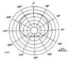
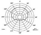
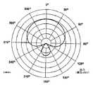
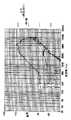
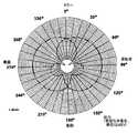
図22A〜22Dおよび図23A〜23Dは、風防の音響抵抗率、サイズおよびマイクロホンハウジングカバー内のポートの位置を調整する効果を示すために、マイクロホン変換器を取り囲むカバーおよび風防を有する場合と有さない場合のマイクロホンアセンブリの極パターンを、4つの異なる周波数でプロットしたものである。パターンは、先ず、カバーおよび風防を所定の位置に置いた場合の、4つの異なる周波数に対する極パターン(図22A〜22D)がプロットされ、次に、図23A〜23Dに示す、カバーおよび風防を取り外した場合の、同じ4つの周波数に対する極パターンがプロットされている。詳細には、図22Aおよび23Aに示す極パターンは、250Hzにおけるマイクロホン特性を示し、図22Bおよび23Bに示す極パターンは、500Hzで取得されたパターンであり、また、図22Cおよび23Cに示す極パターンおよび図22Dおよび23Dに示す極パターンは、それぞれ1000Hzおよび2000Hzで取得されたパターンである。それぞれの極パターンの比較から明らかなように、カバーおよび風防を適切に構成することにより、変換器にカバーが取り付けられていない場合に存在するリアローブが有効に除去される。
【0065】
従来のマイクロホンの場合、典型的には、風防の有孔率を大きくすることによって、風防の音響抵抗率が最小化されているが、本発明によるマイクロホンアセンブリには、風防の有孔率を小さくすることによって音響抵抗率をより大きくした風防が有利に利用されており、音響抵抗率が大きいにもかかわらず、防水特性ばかりでなく、マイクロホンアセンブリの音響特性が改善されている。有効雑音が、一般的にマイクロホンアセンブリの後部および側面に導入されるバックミラーハウジング上にマイクロホンアセンブリを取り付ける場合、このような雑音をフロントガラスデフロスタから導入することができるため、マイクロホンアセンブリの極パターンのリアローブの縮小は、とりわけ有利である。
【0066】
マイクロホン変換器を、独自のカバーおよび風防を有する個別のハウジング内に封止する場合、変換器にもたらされる、車両アクセサリへの変換器の位置決めによって変化するあらゆる影響を補償するために、カバーポートおよび風防の音響抵抗率を変換器毎に異なったものにすることができる。例えば、変換器の1つをバックミラーの面により近づけて取り付ける場合、その変換器の極パターンは、バックミラーの表面から遠く離れた変換器の極パターンとは異なったパターンにすることができる。したがって、適切なカバー設計および風防抵抗率を選択することにより、変換器の位置決めによって異なる影響を、変換器の極パターンおよび他の特性が実質的に同じになるように補償することができる。以上、疎水性織物からなるものとして風防を説明したが、風防を、マイクロホンアセンブリカバーのポートの全面にわたって一体成形することができることについては理解されよう。このような構造により、必要な部品および製造ステップが少なくなるため、マイクロホンアセンブリの製造が簡易化される。また、風防とカバーの間がより有効に封止されることが大いに期待される。
【0067】
図24は、マイクロホンアセンブリ2000のさらに他の実施形態を示したものである。図に示すように、マイクロホンアセンブリ2000は、図18〜20に示す方法と同様の方法で、バックミラーアセンブリのミラーハウジング1630の頂部に取り付けられている。図18〜20に示す実施形態と同様、ミラーハウジング1630の後方上部から展開したデフレクタ1670が設けられており、マイクロホンアセンブリ2000を取り付ける、比較的一様な表面2005を提供している。
【0068】
マイクロホンアセンブリ2000は、2つの個別マイクロホンハウジングを備えている。第1のマイクロホンハウジング2002は、第2のマイクロホンハウジング2004の前方に配置され、かつ、バックミラーアセンブリの面のより近く、したがって車両の運転者のより近くに配置されている。第1のマイクロホンハウジング2002は、音が通過する複数のポート2008を有するカバー2012を備えている。同様に、第2のマイクロホンハウジング2004も、複数の音響ポート2010を有するカバー2014を備えていてよい。ハウジングはいずれも、上で説明した風防と同様の風防を備えていることが好ましい。カバー上のポートの構成および風防の音響抵抗率は、ハウジング2002および2004の各々で異なっていてよく、バックミラーアセンブリに対する変換器の位置決めに起因するあらゆる影響を補償している。
【0069】
マイクロホンハウジング2002および2004の各々は、車両の運転者と向い合う前部表面を有する単一変換器を備えていることが好ましい。図25に示すように、変換器およびカバー2012、2014の中心軸は、バックミラー表面の直角二等分線(すなわち直角)に対して角度θをなす共通軸に沿って整列している。バックミラーの表面は、車両のリアウィンドウを通して見ることができるよう、より大きい角度になっているため、これにより、変換器と運転者の口が確実に同軸上で整列する。変換器は、同軸上で整列させる必要はなく、互いにずらすことができることに留意されたい。このような実施形態については、以下でさらに説明する。
【0070】
以下でさらに考察するように、マイクロホンアセンブリ2000は、2つの変換器の中心が、約1.91cmと3.56cm(0.75インチと1.4インチ)、好ましくは約2.54cmと3.30cm(1.0インチと1.3インチ)の間だけ物理的に間隔が隔たった二次マイクロホンアセンブリであることが好ましい。変換器を3.30cm(1.3インチ)だけ離隔されることにより、変換器と変換器の間の距離が、5kHzの音の波長の約半分になる。この2つの変換器は、上で考察した個別のマイクロホンハウジング内に収納することができる。この好ましい実施形態では、変換器は同じ変換器であり、その間隔は2.54cm(1.0インチ)である。前部変換器は、可能な限り前方に離れていることが好ましく、バックミラーのフロントガラス表面から約0.64cm(0.25インチ)であることが最も好ましい。
【0071】
本発明の一実施形態によれば、各ハウジング内の変換器は、運転者の口に直接向けるのではなく、車両の中心に有効に向くようにポート化されている。変換器を車両の中心に向けることにより、変換器は、依然として運転者の声を明瞭にピックアップすることができ、かつ、運転者によって車両の側面へ向かって発信されるかなりの量の雑音をほとんどピックアップすることはない。典型的な車両の場合、バックミラーは、車両の水平軸に対して約14度と22度の間で位置付けされると、典型的な運転者に対して正しく位置付けされることになる(つまり、車両の水平軸は、車両の車軸の水平軸と平行な軸である)。本発明を説明するために20度が仮定されており、したがって変換器は、バックミラーの表面に直角をなすラインに対して、運転者から遠ざかる方向に20度をなすラインに沿って概ね整列している。その結果、変換器は、車両の中心より低いラインに概ね整列している。また、後部変換器と同軸上で整列しないよう、前部変換器を運転者からさらに遠ざかる方向に若干回転させることも有効である。
【0072】
変換器に必要な感度精度を得るように試行するために、変換器の各々に接続されている利得段にレーザトリムタブが追加されていてもよい。次に、較正された音源によって変換器が音響励起され、変換器の出力がモニタされる。次に、利得を正確に設定し、それにより正確な感度精度を得るために、レーザトリムタブがトリムされる。
【0073】
既存の電話機回路網内のコンポーネントの周波数応答のため、変換器と変換器の間の分離距離を、4.32cmと4.83センチ(1.7インチと1.9インチ)の間まで長くすることは有効であり得る。変換器を取り付けるアクセサリ表面の空間は限られているため、変換器をこのような距離で物理的に分離することは不可能であるかもしれない。この問題を解決するために、第1の変換器と第2の変換器の間に、第1の変換器と第2の変換器の間の音響経路の長さを長くするための機械構造2006が配置されていてもよい。機械構造2006は、任意の対称円錐構造を有することができ、また、図25に示すように、ピラミッドの形をしている。図24から明らかなように、第1のハウジング2002によって第2のマイクロホンハウジング2004に向かって通過するあらゆるオンアクシス音は、機械構造2006を上に向かって通過し、かつ、機械構造2006を超えなければならない。一方、側方からのあらゆるオフアクシス音は、機械構造2006の存在の有無にかかわらず、依然として同じ時間に、マイクロホン構造2002および2004の両方に受信される。試験の結果は、高さ0.89cm(0.35インチ)、辺の寸法1.78cm(0.7インチ)、頂点へ向かう側面の傾斜角45度のピラミッド形機械構造2006により、音響経路の長さが約0.89cm(0.35インチ)だけ長くなりうることを示している。したがって、変換器をより長い距離で物理的に分離することなく、2つの変換器のより長い音響分離が得られる。しがたって、この構造は、比較的狭い表面に取り付けることができる。
【0074】
図24〜26に示すマイクロホンアセンブリ2000の追加共通カバーは、共通ハウジングが実質的に音響的に透明であり、2つの変換器への音の到着時間に影響しないことを条件として、上に示した構造の上に固着することができることに留意されたい。
【0075】
図24および26に示すように、デフレクタ1670の表面は、2020で示す、以下、「微小乱流発生器」と呼ぶ構造を備えている。微小乱流発生器2020は、フロントガラスデフロスタに沿った層空気流がデフレクタ1670の上を通過する際に、デフレクタ1670と層空気流との間に微小乱流が生成されるよう、織物または他の微小構造を使用して実施することができる。好ましい微小乱流デフレクタは、VELCRO(登録商標)フック・アンド・ループ・ファスナなどのフック・アンド・ループ型ファスナのループ部分を使用して実施することができる。別法としては、デフレクタ1670の対応する表面を単純に粗くすることにより、同様の乱流を生成することもできる。
【0076】
乱流によって雑音が生成されるため、一般的には乱流は望ましくないが、提案する方法で極めて微小な乱流を生成することにより、人間の可聴限界内のより低い周波数成分を生成する、デフレクタ1670を通過する空気の乱流を小さくする一方で、人間の可聴限界を超えた周波数成分を有する乱流が生成される。デフレクタ1670の表面に沿って生成される微小乱流により、層空気流が、デフレクタ自体によって生成される微小乱流以外の微小乱流によって偏向され、それにより、層空気流から見たデフレクタの摩擦が小さくなり、したがって、空気流によって生成される、より周波数の低い可聴周波数領域内の雑音を生成することになりがちな乱流が小さくなる。
【0077】
ミラー表面のサイズが大きく、かつ、最も前方の変換器がミラー表面に近接しているため、2つの変換器の極パターンを、周波数依存ベースで互いに変化させることができる。アプリケーションの中には、周波数領域にわたって極パターンを変更するために、2つのマイクロホンハウジングの各々に第2の変換器を備え、それにより、この相異を補償することが望ましいアプリケーションもある。これらの追加変換器を利用し、かつ、極を周波数に関して修正するための付加信号を利用することにより、所望する全通過帯域にわたって、ほぼ同一で、かつ、最適なカージオイド極応答を得ることができる。本発明の一実施形態によれば、前部マイクロホンハウジング内の第2の変換器は、全方向性変換器であってよく、後部マイクロホンハウジング内の第2の変換器は、カージオイド変換器であってよい。
【0078】
図27は、図24〜26に示す二次マイクロホンアセンブリ2000と共に使用されるマイクロホン処理回路2100のブロック図を示したものであるが、マイクロホン処理回路2100は、バックミラーアセンブリ、他の車両アクセサリ、あるいは車両環境以外の他の任意のオーディオアプリケーションへの組込み如何にかかわらず、任意の二次マイクロホンアセンブリに使用することができることは理解されよう。
【0079】
回路2100は、前部変換器2102および後部変換器2104を備えている。二次マイクロホンアセンブリの場合、上で考察したように、前部変換器および後部変換器は、変換器の前部表面を会話者の方向に向けて配置されることが好ましい。後部変換器2104の出力部2104aは、広域通過フィルタ2106の入力部2106aに結合されている。広域通過フィルタの出力部2106bは、加算回路2108の第1の入力部2108aに結合されている。
【0080】
前部変換器2102の出力部2102aは、全域通過移相器2110の入力部2110aに結合されている。全域通過移相器2110の出力部2110bは、加算回路2108の反転入力部2108bに結合されている。以下でさらに考察するように、移相器2110は、前部変換器2102からの信号が反転され、後部変換器2104からのフィルタリングされた信号と加算される(すなわち、信号が効果的に控除される)加算回路2108への印加に先立って、前部変換器2102および後部変換器2104からの信号が同じ量だけシフトした位相を有するように、前部変換器2102からの信号の位相を、広域通過フィルタ2106に固有の移相に等しい量だけシフトさせるためのものである。加算回路2108の出力部2108cは、3極広域通過フィルタ2112の入力部2112aに結合されている。3極広域通過フィルタ2112の出力部2112bは、任意選択のバッファ回路2114の入力部2114aに結合されている。バッファ回路2114の出力2114bは、本発明のマイクロホン処理回路の出力を表している。
【0081】
図27に示すマイクロホン処理回路2100は、コンポーネント2106〜2114の各々に印加されるバイアス電圧VBを生成するバイアス回路2116を備えている。バイアス電圧VBの印加については、コンポーネント2106〜2114の個々の略図に、より明確に示されている。バイアス回路2116は、電源電圧VSと接地の間に結合された1対の直列接続抵抗2118および2120を備えている。抵抗2118および2120の抵抗値は、10kΩであることが好ましい。バイアス回路2116は、さらに、バイアス回路2116の出力部と接地の間に結合されたコンデンサ2122を備えている。コンデンサ2122の容量は、2.2μfであることが好ましい。
【0082】
図28A〜28Eは、コンポーネント2106〜2114の詳細を略図で示したもので、一般的な回路動作についての説明に続いて、以下でさらに詳細に考察されている。
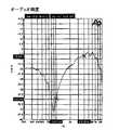
本発明のマイクロホン処理回路2100の性能および利点を理解するためには、最初に、二次マイクロホンアセンブリと共に使用されている従来の回路の性能を理解しておく必要がある。従来の二次マイクロホン処理回路では、前部変換器の出力が単純に反転され、反転信号と後部変換器から直接供給される信号を加算する加算回路に供給されている。図29Aは、このような処理回路の周波数応答を示したものである。図29AのプロットAは、二次マイクロホンアセンブリの、オンアクシスで発信される音を有する様々な周波数に対する感度を示している。プロットBは、軸から180度をなして(すなわち、マイクロホンアセンブリの後方から)発信される音を有する様々な周波数に対するマイクロホン感度を示している。プロットCは、変換器の中心軸から90度の角度で(すなわち、マイクロホンアセンブリの側方から直接)到着する様々な周波数に対するマイクロホン感度を示している。図29Aから明らかなように、このようなマイクロホン回路は、オンアクシスで発信される音に対して、より高い周波数に対しては極めて敏感であるが、可聴帯域内のより低い周波数に対しては極めて鈍感である。低周波感度を補償するために、加算回路の出力部に広域通過フィルタが追加されている。このような構造は、可聴範囲の全周波数にわたって、より一様な感度を提供する役割を果たしているが、フィルタの導入により、アセンブリは、振動誘導雑音に対して極端に敏感になっている。より詳細には、このような構成を使用することにより、変換器のねじり振動が増幅されている。
【0083】
これらの問題を解決するために、本発明のマイクロホン処理回路は、一方の変換器と加算回路2108の間に広域通過フィルタ2106を利用している。広域通過フィルタ2106は、前部変換器2102または後部変換器2104のいずれかの出力部に置くことができる。広域通過フィルタ2106は、約1kHzの特性遮断周波数を有していることが好ましい。一方の変換器の出力を控除する前に、もう一方の変換器の出力をフィルタリングし、その低音周波数成分を小さくすることにより、結果として得られる出力の低音の減少量が、フィルタ2106が存在しない場合の減少量より小さくなる。上で考察したように、全域通過移相器2110が、もう一方の変換器の経路内に設けられており、それにより、前部変換器2102および後部変換器2104からの信号の位相が、加算回路2108に到達する前に同じ量だけ確実にシフトされる。図29Bは、移相器2110を利用しない場合のシステムの周波数応答を示したものである。図29Bから明らかなように、可聴周波数領域の中間で、周波数応答が急激に低下している。これは、移相器2110を利用しない場合に加算回路2108に印加されることになる、信号の位相差によるものである。
【0084】
図29Cは、概ね図27、とりわけ以下でさらに説明する図28A〜28Eに示す構造を有する本発明のマイクロホン処理回路2100の周波数応答を示したものである。図29Cから明らかなように、オンアクシス音に対するマイクロホンアセンブリの感度は、全可聴周波数領域にわたって比較的一様である。図29CのプロットAは、オンアクシス感度を示している。図29CのプロットBは、180度オフアクシス音感度を示している。プロットCは、145度のオフアクシスで到着する音に対するマイクロホンアセンブリの感度を示し、また、プロットDは、90度オフアクシスのポイントから発信される音を表している。これらのプロットの比較から明らかなように、本発明による二次マイクロホンアセンブリは、オンアクシス音に対して著しく敏感であり、オフアクシス音、とりわけより低い周波数に対しては、明らかに感度が劣っている。上で言及したように、自動車環境においては、雑音の大部分は、マイクロホンアセンブリの側面に向かってオフアクシスで到着する。したがって、上で説明した二次マイクロホンアセンブリ2000および回路2100は、これらの方向から発信される雑音に対して、著しく鈍感である。
【0085】
図28Aは、広域通過フィルタ2106の好ましい構造を略図で示したものである。広域通過フィルタ2106は、フィルタの入力部2106aと電源電圧VSの間に結合された、抵抗値が8.2kΩであることが好ましい第1の抵抗2124を備えている。0.001μfの容量であることが好ましいコンデンサ2126が、入力部2106aと接地の間に結合されている。また、広域通過フィルタ2106は、非反転入力端子がバイアス電圧VBに結合され、かつ、反転入力部が、直列に接続されたコンデンサ2130および抵抗2132を介して入力端子2106aに結合された、部品番号LM2904であることが好ましい演算増幅器2128を備えている。コンデンサ2130は、0.01μfのコンデンサであることが好ましく、また、抵抗2132の抵抗値は、10kΩであることが好ましい。また、広域通過フィルタ2106は、反転入力部と増幅器2128の出力部の間に結合された帰還抵抗2134を備えていることが好ましい。増幅器2128の出力部と接地の間に、もう1つの抵抗2136が結合されている。抵抗2134および2136の抵抗値は、いずれも10kΩであることが好ましい。増幅器2128の出力は、広域通過フィルタ2106の出力2106bとして機能している。
【0086】
図28Bは、全域通過移相器2110の好ましい構造を示したものである。移相器2110は、入力端子2110aと電源電圧VSの間に結合された第1の抵抗2138を備えている。抵抗2138の抵抗値は、8.2kΩであることが好ましい。0.001μfの容量であることが好ましいコンデンサ2140が、入力端子2110aと接地の間に結合されている。入力端子2110aと増幅器2146の反転入力部の間に、コンデンサ2142および抵抗2144が直列に結合されている。コンデンサ2142の容量は、1μfであることが好ましい。増幅器2146の反転入力部と出力部の間に、帰還抵抗2148が結合されている。増幅器2146の出力部と接地の間には、抵抗2150が結合されている。増幅器2146は、部品番号LM2904であることが好ましい。増幅器2146の非反転入力部とバイアス回路2116の間に、もう1つの抵抗2152が結合されている。コンデンサ2154は、増幅器2146の非反転入力部と、コンデンサ2142と抵抗2144の間の端子との間に結合されている。コンデンサ2154の容量は、0.01μfであることが好ましい。抵抗2144、2148、2150および2152の抵抗値は、すべて10kΩであることが好ましい。増幅器2146の出力は、移相器2110の出力2110bとして機能している。
【0087】
図28Cは、加算回路2108の好ましい構造を示したものである。加算回路2108は、バイアス電圧VBを受け取るために、非反転入力部がバイアス回路2116に結合された増幅器2156を備えている。入力端子2180aは、直列に接続されたコンデンサ2158および抵抗2160を介して、増幅器2156の反転入力部に結合されている。同様に、入力端子2180bは、直列に接続されたコンデンサ2162および抵抗2164を介して、増幅器2156の反転入力部に結合されている。コンデンサ2158および2162の容量は、1μfであることが好ましい。増幅器2156の反転入力部と出力部の間に、抵抗2166が結合されている。抵抗2168は、増幅器2156の出力部と接地の間に結合されることが好ましい。抵抗2160、2164および2168の抵抗値は、すべて10kΩであり、一方、抵抗2166の抵抗値は100kΩであることが好ましい。増幅器2156は、部品番号LM2904であることが好ましい。増幅器2156の出力は、加算回路2108の出力2108cとして機能している。
【0088】
図28Dは、3極広域通過フィルタ2112の好ましい構造を示したものである。側路フィルタ2112は、増幅器2170および入力部2112aと増幅器2170の非反転入力部の間に直列に結合された3つのコンデンサ2172、2174および2176を備えていることが好ましい。コンデンサ2172、2174および2176の容量は、0.33μfであることが好ましい。接地と、コンデンサ2172と2174の間の端子との間に、抵抗2178が結合され、増幅器2170の反転入力部と、コンデンサ2174と2176の間の端子との間に、抵抗2180が結合され、また、増幅器2170の非反転入力部とバイアス回路2116の間に、抵抗2182が結合されている。増幅器2170の出力部と接地の間には、抵抗2184が結合されている。増幅器2170の反転入力部および出力部は電気結合されている。抵抗2178の抵抗値は、6.8kΩであることが好ましく、抵抗2180の抵抗値は、1.1kΩであることが好ましく、抵抗2182の抵抗値は、270kΩであることが好ましく、また、抵抗2182の抵抗値は、10kΩであることが好ましい。増幅器2170は、部品番号LM2904であることが好ましい。増幅器2170の出力は、フィルタ2112の出力2112bとして機能している。この構造にすることにより、この広域通過フィルタの遮断周波数が約300Hzになる。マイクロホン処理回路2100には、異なる遮断周波数を利用することができることに留意されたい。
【0089】
図28Eは、バッファ回路2114の好ましい構造を示したものである。バッファ回路2114は、非反転入力部がコンデンサ2188を介して入力端子2114aに結合された増幅器2186を備えていることが好ましい。増幅器2186の非反転入力部とバイアス回路2116の間に、抵抗2190が結合されている。増幅器2186の反転入力部は、直列に接続された抵抗2192およびコンデンサ2194を介して接地に結合されている。増幅器2186の反転入力部と出力部の間に、抵抗2196が結合されている。増幅器2186の出力部と接地の間に、抵抗2198が結合されている。コンデンサ2199は、増幅器2186の出力部とバッファ回路2114の出力部2114bの間に結合されている。
【0090】
以上、マイクロホン処理回路2100の特定の回路実施態様について説明したが、本発明の範囲を逸脱することなく、他の構成を利用することができることは、当分野の技術者には理解されよう。
【0091】
アプリケーションの中には、マイクロホンアセンブリから出力される周波数応答に対する車両の影響を補償するために、特定の周波数領域における変換器の利得を故意にブーストすることが望ましいアプリケーションもある。例えば、5kHzまで概ね一様な周波数応答曲線を有するマイクロホンアセンブリが構築されたが、このマイクロホンアセンブリは、特定の車両に置かれると、一様な周波数応答を維持するのは、せいぜい約3.5kHzまでであり、3.5kHzと5kHzの間で、幾分か大きく低下する。したがって、マイクロホンアセンブリの出力に対する車両の影響を補償するために、マイクロホンアセンブリに非一様応答曲線を与え、それにより、これらの影響を補償し、5kHzまで一様な出力信号をマイクロホンアセンブリから提供するために、3.5kHzと5kHzの間の周波数帯域が故意にブーストされている。音声認識処理を利用する場合、このような5kHzまで一様な出力が一般的に望ましい。
【0092】
図30は、ディジタル信号プロセッサ(DSP)を利用した代替マイクロホン処理回路を示したものである。
図30に示すように、アイクロホンアセンブリは、1つまたは複数の変換器2210を備えている。アイクロホンアセンブリのマイクロホン処理回路は、DSP2220を備えており、また、任意選択で、DSP2220への入力と、1つまたは複数の変換器2210のうちの1つの出力との間に配置された予備処理回路2215を備えている。別法としては、DSP2220を、予備処理回路2215と1つまたは複数の変換器2210の間に結合することもできる。DSP2220の出力は、音声認識装置、記録装置などの様々な装置、あるいは無線のトランシーバまたはセルラ電話に印加することができる。
【0093】
DSP2220は、適切な任意の構成のDSPにすることができるが、Texas Instrumentsが市販している部品番号TMS320VC5X5409か5402のいずれかであることが好ましい。マイクロホンは、必ずしもそうである必要はないが、上で開示した構造の複数の変換器を備え、かつ、上で開示した予備処理回路など、対応する予備処理回路を回路2215に使用することもできる。2つの変換器を使用し、一方を会話者から遠くに離隔されて配置することにより、変換器がピックアップする音の到着時間を利用して、もっともらしい音源を決定することができる。例えば、会話者に最も近い変換器は、最も遠くにある変換器が検出する前に、その会話者が発信する音を検出することができる。逆に、最も遠くにある変換器が最初に検出する音は、すべて雑音と見なすことができる。同様に、オフアクシスで着信する、両方の変換器で同時に受信される音も、すべて雑音として除去することができる。
【0094】
人間の声帯は共鳴し、それにより、上音を有する単一周波数が生成される(高調波としても知られている)。したがってすべての声帯エネルギーは、声帯基本振動数の高調波に限定されている。基本振動数は、男性の場合、通常、35Hzと120Hzの間であり、女性の場合は、通常、85Hzと350Hzの間である。本発明によるDSPフィルタ2220は、1つまたは複数の変換器2210が受信した音声信号の基本振動数を識別し、識別した基本振動数を使用して、音声信号を発信する1人または複数人の声帯の高調波のみを通過させる反転櫛形フィルタの係数を計算している。雑音の識別を試行する従来の雑音フィルタとは対照的に、本発明のフィルタは音声を識別している。また、本発明のフィルタを使用して、両者の基本振動数が異なっていることを条件とし、一方の会話者を他者から区別することができる。
【0095】
図31は、DSP2220中に実施される適応フィルタのプロセス線図を示したものである。ブロック2225に示すように、1つまたは複数のマイクロホン変換器2210からのアナログ可聴信号がディジタル可聴信号に変換される。次に、ブロック2230に示すように、ディジタル化された可聴信号に対する高速フーリエ変換(FFT)が実施される。図32は、音声信号および雑音を含んだ可聴信号のFFTの一例を示したものである。ブロック2235に示すように、ディジタル化された可聴信号のFFTを使用して、音声信号の基本振動数が決定される。DSP2220は、FFT中の所定の閾値を超えた振幅を有する周波数成分を識別することによって基本振動数を識別し、続いて、所定の閾値を超えた振幅を有する周波数成分の周波数の差として、基本振動数を識別している。図32に示す例示的FFTから明らかなように、最も高いピークは、基本振動数f0に等しい量で分離され、基本振動数の整数倍の周波数で出現している。FFT中のこれらのピークは、個人の音声の高調波振動数成分に対応している。
【0096】
ブロック2235で基本振動数が決定されると、適応フィルタ係数が生成され(ブロック2240)、生成された適応フィルタ係数を使用して、1つまたは複数の変換器(2210)によって供給される、ディジタル化された可聴信号をフィルタリングするために使用される反転櫛形フィルタ(ブロック2245)が構成される。図33は、図32に示すFFTを有する信号のフィルタリングに適した反転櫛形フィルタ特性の一例を示したものである。次に、ブロック2250に示すように、フィルタリングされたディジタル信号がアナログ音声信号に変換される。DSP中における反転櫛形フィルタの構成方法の考察については、Ken Steiglitz著「Digital Signal Processing Primer」(1996年、ISBN 0−8053−1684−1)を参照されたい。
【0097】
図33に示すように、反転櫛形フィルタは、所定の周波数、例えば2500Hzを超えるすべての周波数成分を通過させる。「S」、「Sh」、「T」および「P」音などの、人間の音声中の特定のより高い周波数音は、声帯の高調波振動数で生じる音ではないため、このことは有利であるかもしれない。雑音のほとんどがより低い周波数で生じる車両環境では、より高いすべての周波数成分を通過させることによる問題は、一般的には存在しない。以下でさらに説明するように、DSP2220は、人間の音声中のこのような「S」、「Sh」、「T」および「P」音を予測し、それにより、より高い周波数のこれらの音と雑音とを分離するように構成することができる。スペクトル控除などのフィルタリングは、反転櫛形フィルタリング周波数を越える領域で使用され、その帯域の雑音が低減される。
【0098】
DSP2220は、着信する可聴信号の基本振動数のあらゆる変化を連続的にモニタすることにより、検出した基本振動数のあらゆる変化に応じてフィルタ係数を調整している。DSP2220によるフィルタ成分の調整方法は、例えば車両の他の搭乗者の会話によって生じる突然の変化を避けるために予め構成されており、したがって会話者の望ましい周波数応答を予測し、かつ、維持することができる。応答の一貫性は、音声認識における重要な要素である。この調整は、基準時間インターバルに対する高調波の相対強度を比較することによってなされ、この関係が維持される。例えば、最初のいくつかの発声における第二平均高調波ピークの値は、第三平均高調波ピークの値より3dB大きい。この関係が変化すると、最初の値が復元される。この概念は、歯擦音発声の相対強度および声帯レベルにも適用することができる。結果として生じる音声出力は、個人の正規の音調を正確に再生していないが、一貫した音調を再生している。出力レベルと結合したこの調整により、2つの極めて重要な変数が除去され、それにより音声認識が促進される。
【0099】
また、DSP2220が、車両内の異なる個人の高調波にそれぞれ対応する複数の重畳反転櫛形フィルタを構成していることについても留意されたい。また、システムには、後で基本振動数を識別することに起因する遅延を制限するために、起動時に最も頻繁に識別される、あるいは起動時に最後に識別された基本振動数に対して初期設定するように教え込むこともできる。
【0100】
図31のブロック2255および2260は、DSP2220内で任意選択で実施される本発明の可変利得調整を示している。アナログ信号への変換に先立って、フィルタリングされたディジタル化信号の利得が変更されうる(ブロック2255)。利得の変更量は、1つまたは複数の変換器2210から受け取る、運転者の方向にヌルが向けられたカージオイドまたは超カージオイドであることが好ましい極パターンに対応するディジタル化可聴信号の中から検出される雑音レベルの関数である。
【0101】
図34は、DSP2220の第2の構成を示したものである。第2の構成によれば、それぞれ超カージオイドに対応する極パターンを有する2つの変換器が使用されている。第1の変換器2302は、会話者(自動車の環境においては、通常、運転者)に向かってオンアクシスで導かれ、第2の変換器2304は、反対方向に、極中のヌルを会話者に向けて配置されている。この方法によれば、第1の変換器2302が、個人の音声および若干の雑音をピックアップし、一方、第2の変換器2304は、個人の音声をピックアップすることなく、第1変換器2302がピックアップする若干の雑音のほとんどを含む雑音のみをピックアップする。したがって、第1の変換器2302の出力信号から第2の変換器2304の出力信号が控除され、不要な雑音が除去される。別法としては、第2の変換器2304に全方向性極パターンを持たせることもできる。
【0102】
図34の線図は、第1の変換器2302の可聴信号がディジタル可聴信号に変換され(ブロック2306)、また、第2の変換器2304の可聴信号も同様にディジタル可聴信号に変換される(ブロック2308)ことを示している。ディジタル化された両変換器からの可聴信号は、音声の存在を検出するために処理され(ブロック2310)、かつ、互いに比較される(ブロック2312)。第1の変換器2302および第2の変換器2304からの信号の比較に応じて、変換器2304からの信号の利得/位相が選択的に調整される(ブロック2314)。利得/位相が調整された、第2の変換器2304からの信号は、反転され(ブロック2316)、ディジタル化された第1の変換器2302からの信号と加算される(ブロック2318)。得られた加算信号は、任意選択でアナログ信号に変換される(ブロック2320)。加算された信号は、実際に、第2の変換器2304からの調整済み可聴信号を、第1の変換器からの調整済み信号から控除した信号に対応しているため、加算された信号は、あらゆる雑音が除去された音声を表している(音声が存在している場合)。音声が存在しない場合、加算された信号はヌルである。音声は、受信した可聴信号に対してFFTを実施し、人間に期待される範囲内の基本振動数から探索することによって検出される。
【0103】
第2の変換器2304からの信号の利得/位相を適切に調整するために、音声の存在の検出(ブロック2310)を使用して、実施すべき適切な利得/位相調整が決定されうる。また、第2の変換器2304からの信号の利得/位相調整に使用するために、加算された信号の中からヌルが検出されうる(ブロック2322)。
【0104】
図34に示すように、若干の位相調整(ブロック2324)を施し、第1の変換器2302からの可聴信号に、第2の変換器2304からの可聴信号の反転時(ブロック2316)に固有に導入される位相遅延に対応する位相遅延を導入することが望ましい。
【0105】
図34に示すシステムは、音声と音声の間の期間中における利得の突然のブーストを防止し、それにより、これらの期間中における雑音レベルのブーストが確実に回避されるよう、音声が検出された場合にのみ、信号の利得を調整するように構成されている。この構成により、自動利得制御を使用する場合に典型的に付き纏う、音声と音声の間の期間中に利得が自動的に大きくなり、それにより不要な雑音が増幅される問題が解決される。
【0106】
図31および34に概略した機能は、いずれも全面的あるいは部分的に組み合わせることにより、音声処理における様々な重要な改善が得られることに留意すべきである。
また、本発明には、発声音韻を識別し、かつ、発声音韻を正確に再生するために、声帯事象と歯擦音の発生との間の時間関係が使用されている。この時間関係により、処理遅延が付加されるが、音声認識が著しく改善される。音声事象が発生したことを知ることにより、システムは、先行する時間インターバルに対する小さな差異を探索することができる。可能性の数には限界があり、また、雑音のため、本来の音が、より固有の声帯雑音よりもより一般的に再生される。例えば、システムは、「Sh」音が発声されたことを検出し、かつ、「Sh」音を完全に再生することができる。他の発声音には、「S」、「T」および「P」音がある。これらはすべて、その性格が十分に定義されている単純な雑音バーストである。
【0107】
分離された変換器周辺の環境により、各変換器の周波数応答および極が著しく乱される。例えば、バックミラーアセンブリのミラーの前部表面により近接して配置される変換器と、より後方に配置される変換器の極および周波数応答は異なっている。本発明のシステムは、音響調整と適応調整を組み合わせることにより、これらの誤差を補償することができる。適応帯域に対する変換器の平衡を帯域ベースで調整し、各帯域における優勢音響雑音を最小化することができる。これにより、可能な最大雑音減少が保証される。このような調整は、音声発声と音声発声の間のインターバルの間にのみ実施されることが好ましい。結果として生じる音声レベルのあらゆる減少は自動的に補償される。雑音の減少は、音声レベルのあらゆる損失より大きく、それにより最大信号対雑音比が保証される。
【0108】
通常、DSPを使用している複雑な音響再生装置における唯一制御されたアナログアスペクトは利得制御である。他のほとんどの方法では、マイクロホンおよびそのアナログ特性は、所定の特性を有しているものと仮定されており、その結果、DSPのアプリケーションは、そのマイクロホンの所定の周波数応答の近傍で開発されている。最終的に得られる状況として、マイクロホンが正しく機能するためには、マイクロホンは、設計が意図した周波数応答と同じ周波数応答を有していなければならない。この状況により、マイクロホンの周波数応答の変化が防止され、それにより潜在的に他の利点が提供されることになる。
【0109】
雑音が優位を占める周波数帯域のアナログ感度を小さくすることにより、極めて重要な利点が得られる。利得制御が設けられている場合、通常、最も高い入力信号によって利得レベルが設定される。動的利得制御が設けられていない場合、システムの利得は、通常、最も高いことが期待される入力信号に対応する固定レベルに設定される。利得制御を有するシステムでは、雑音が支配的である場合、その雑音によって利得のレベルが設定される。この作用により、最適音声入力に対する利得の適正な設定が効果的に回避される。
【0110】
存在している雑音により、音声信号の振幅より大きい振幅を有する信号が生成される場合、雑音によって生成される信号がアナログ段におけるクリッピングの原因になり、それにより、総ひずみおよび極めて大きい偽雑音アーチファクトがもたらされる可能性がある。
【0111】
本発明は、2つの異なる手法を使用して、上に挙げた問題に対処している。第1の手法によれば、所望のマイクロホン/アナログ応答が生成され、かつ、初期設計周波数応答からオフセットしたテーブルが生成される。このテーブルは、DSPソフトウェアによって使用され、ディジタル化されたデータによって生成される、設計されたマイクロホンが同じ条件でもたらしたであろう値が修正される。つまり、そのDSPソフトウェア向けに設計された周波数応答とは異なる周波数応答を有するマイクロホンを利用するために、そのシステムのDSPソフトウェアを修正する必要がない。オフセットテーブルは、使用されているマイクロホンが異なる周波数応答を有している場合であっても、DSPがその設計マイクロホンに対して期待するマイクロホン周波数応答を提供するためのものである。それにより、音声認識が使用されているアプリケーションなど、特定のアプリケーションにより適した周波数応答を有するマイクロホンを使用することができる。この手法は、DSPによって実施される、一般的にはFFTである第1の処理中に生じるため、現在、マイクロホンの周波数応答の柔軟性を制限している、ソフトウェアに対する影響に関しては何の問題もない。
【0112】
上で考察した第1の手法は、設計値近辺の応答とは異なる固定周波数応答が仮定されている。適切なDSPソフトウェアを必要とする、より強力な用法を適応させることが可能である。この形態では、DSPソフトウェアは、アナログ周波数応答を動的に制御することができる。DSPソフトウェアは、例えば、雑音が所与の周波数帯域において支配的であることを決定し、その場合、その周波数帯域内の信号を減衰させることができる。また、DSPソフトウェアは、特定の周波数帯域における音声が、十分ではないが支配的であるかどうかを決定し、その周波数帯域の利得を大きくすることもできる。DSPソフトウェアには、このアクションによる影響が分かるため、DSPソフトウェアは、ディジタル化後の処理によって補償することができる。
【0113】
アナログ周波数応答のこのような動的制御および適応制御を利用することにより、アナログ部分の全ダイナミックレンジ、特にCODECを使用した音声処理が保証される。周波数帯域間の信号成分の総差異が除去され、すべての音声信号帯域が、結果として生じるデータ中に存在することが保証される。ウィンドフラッタなど、雑音の中には音声との区別が困難な雑音もあるため、ある程度の仮定雑音が存在している。これは、低音応答が一般的に他の帯域より縮小されていることを意味している。
【0114】
要約すると、上記2つの手法は、偶然の結果を招くことなく直接変更するにはマイクロホンの特性があまりにも徹底し過ぎている反覆設計の利点を維持しつつ、アナログ周波数応答の最適化を追求している。
【0115】
本発明の他の態様によれば、信頼性の高い連続性が、マイクロホンアセンブリと電子アセンブリを取外し可能に結合する2線式マイクロホンインターフェースを介して提供される。マイクロホンアセンブリは、電源および2線式マイクロホンインターフェースを備えている。2線式マイクロホンインターフェースは、可聴信号を電子アセンブリに提供する2つの接点を備えている。低インピーダンス経路がマイクロホンアセンブリと電子アセンブリの間に維持されるよう、2つの接点を介して連続直流電流が供給される。
【0116】
図35は、電子アセンブリ2402(例えば、差動増幅器段)に結合されたマイクロホンアセンブリ(従来技術によるマイクロホンインターフェースを含む)2400の簡易電気図を示したものである。図35の回路に示すように、電源(VAUDIO)を介してマイクロホン2400に電力が供給されている。VAUDIOは、抵抗R5の第1の端部に結合されている。抵抗R5の第2の端部は、コネクタJ1の接点2に結合されている。コネクタJ1の接点2は、整合すると、コネクタJ1の接点4および抵抗R6の第1の端部に結合される。抵抗R6の第2の端部は、抵抗R14の第1の端部に結合されている。抵抗R14の第2の端部は、コネクタJ1の接点3に結合されている。コネクタJ1の接点3は、コネクタJ1の接点1に結合され、コネクタJ1の接点1は、抵抗R11の第1の端部に結合されている。抵抗R11の第2の端部は、電子アセンブリ2402の共通接地に結合されている。
【0117】
簡潔に説明すると、VAUDIOは、抵抗R5を介してマイクロホンアセンブリに電力を提供している。抵抗R5およびR6を流れる電流が、フィルタリングされたマイクロホン電源(VMIC)を提供する役割を果たすコンデンサC4に充電電流を提供している。VAUDIOは、抵抗R5、コネクタJ1の接点2および4、抵抗R6、抵抗R14、コネクタJ1の接点3および1、および抵抗R11を介して連続ウェット電流(DC)を提供している。抵抗R6の第1の端部および抵抗R14の第2の端部に結合されたトランジスタQ1は、マイクロホン前置増幅器によって提供される負荷を表している。
【0118】
図36を参照すると、電子アセンブリ2502(例えば、差動増幅器段)に結合されたマイクロホンアセンブリ2500(本発明の一実施形態によるマイクロホンインターフェースを含む)の簡易電気図が示されている。VAUDIOは、抵抗R5の第1の端部に結合されている。抵抗R5の第2の端部は、抵抗R6の第1の端部に結合されている。抵抗R6の第2の端部は、コネクタJ1の接点2に結合されている。コネクタJ1の接点2は、整合すると、コネクタJ1の接点4および抵抗R12の第1の端部に結合される。抵抗R12の第2の端部は、抵抗R8の第1の端部に結合されている。抵抗R8の第2の端部は、抵抗R13の第1の端部に結合されている。抵抗R13の第2の端部は、コネクタJ1の接点3に結合されている。コネクタJ1の接点3は、コネクタJ1の接点1に結合されている。コネクタJ1の接点1は、抵抗R11の第1の端部に結合されている。抵抗R11の第2の端部は、電子アセンブリ2502の共通接地に結合されている。
【0119】
図36に示すように、補助電源(V1)がマイクロホンアセンブリ2500(またはマイクロホンアセンブリ2500の少なくとも一部)に電力を提供している間、電子アセンブリ2502の電源VAUDIOによってウェット電流(DC)が供給される。ウェット電流(DC)は、VAUDIOから抵抗R5、抵抗R6、コネクタJ1の接点2および4、抵抗R12、抵抗R8、抵抗R13および抵抗R11を介して供給される。本発明によるマイクロホンインターフェースは、補助電源から電力を受け取る、より性能の高い、例えばディジタル信号プロセッサ(DSP)が組み込まれたマイクロホンアセンブリにウェット電流を提供している。本発明により、非貴金属接点を有するコネクタを使用することができるため、インターフェースのコストが低減され、かつ、マイクロホンアセンブリ2500と電子アセンブリ2502の間に信頼性の高い接続が提供される。抵抗R5、R6、R8、R11、R12およびR13の値は、マイクロホンアセンブリおよび関連するすべての増幅器の利得および帯域幅に悪影響を及ぼさないことを条件として、幅広く選択することができる。必要に応じて、抵抗R5またはR6のいずれか一方を短絡に置き換えることもできる。また、必要に応じて、抵抗R11、R12およびR13を短絡に置き換えることもできる。その場合、抵抗R8およびR5またはR6の値は、適切な量のウェット電流を提供するために選択される。例えば、VAUDIOが12ボルトで、1ミリアンペアのウェット電流が望ましい場合、仮に2kΩの抵抗を抵抗R5に選択し、かつ、抵抗R6、R11、R12およびR13を短絡すると、抵抗R8には10kΩの抵抗が選択されることになる。これらの抵抗が、より一般的にはインピーダンスである(例えば、R8をチョークあるいは能動回路にすることができる)ことは、当分野の技術者には理解されよう。図36に示すコンポーネントの値は、利用するマイクロホンアセンブリの概ね許容可能な性能を提供している。
【0120】
図37は、ウェット電流が補助電源(V1)から供給される、本発明によるさらに他の実施形態を示したものである。ウェット電流(DC)は、電源V1から抵抗R5、抵抗R12、コネクタJ1の接点4および2、抵抗R8、コネクタJ1の接点1および3、および抵抗R11を介して供給される。必要に応じて、抵抗R11、R12およびR13を短絡に置き換えることもできる。その場合、抵抗R5およびR8の値は、適切な量のウェット電流を提供するために選択される。図37に示す実施形態は、マイクロホンアセンブリ2600の製造者の観点からすると、電子アセンブリ2602の製造者が提供する必要のあるコンポーネントが、コネクタJ1の接点1および2の両端間の抵抗R8のみである点で、とりわけ有用である。
【0121】
図38は、マイクロホンアセンブリ2700から電子アセンブリ2702に提供される入力が平衡した、本発明によるさらに他の実施形態を示したものである。ウェット電流(DC)は、電源(V1)から抵抗R15、抵抗R16、コネクタJ1の接点4および2、抵抗R8、コネクタJ1の接点1および3、および抵抗R20を介して供給される。必要に応じて、抵抗R16、R17およびR20を短絡に置き換えることもできる。その場合、抵抗R8およびR15の値は、適切な量のウェット電流を提供するために選択される。ウェット電流(DC)は、マイクロホンアセンブリのリード線の1つに接続された電圧源、抵抗、定電流源、誘導子または他の電源から供給されている。ウェット電流回路を完成するためのDC経路をマイクロホンが有している場合、電流源は本質的ではない。
【0122】
図38に示すように、可聴周波音は、マイクロホンアセンブリの出力段から電子アセンブリ2702へAC結合されている。本発明は、マイクロホンアセンブリまたは電子アセンブリが備えているマルチコネクタに拡張することができる。本発明によれば、ウェット電流を維持するために、すべてのコネクタにDC電流が流れる。したがって本発明による実施形態を利用した回路には、接点の酸化による不利な影響はない。また、マイクロホンに入力されるDC電圧を使用して、組込み試験機能のためのインターフェースの連続性を検証することができる。
【0123】
図39A〜39Dは、デフレクタ1670がクロスデフレクタ部分3000を備えた、本発明による代替実施形態を示したものである。クロスデフレクタ3000は、フロントガラスで反射する音にクロスを透過させ、マイクロホンアセンブリに到達させる一方で、デフロスタからの空気流を有利にマイクロホンアセンブリから遠ざけて偏向させている。クロスデフレクタ部分3000により、デフレクタ1670をよりコンパクトにすることができる。デフレクタ1670をよりコンパクトにすることにより、デフレクタ1670がフロントガラスに当たる可能性、およびバックミラーアセンブリをフロントガラスに向かって上方に移動させる際の制限がより少なくなることが期待される。クロスデフレクタ部分3000を使用することなく、デフレクタを単純によりコンパクトにした場合、その効果ははるかに小さい。クロスデフレクタ部分3000は、クロスデフレクタ部分3000を有さない場合にデフレクタ1670が展開する以上に、上方に展開しているが、クロス部分3000は変形可能であるため、ミラーアセンブリの上方への移動を制限することはなく、また、好ましいことには、フロントガラスと接触して、マイクロホンアセンブリへの空気流の到達がさらに防止される。
【0124】
クロスデフレクタ部分3000は、音を通過させるには十分であり、かつ、有効空気流にクロスを通過させることのない開口であるウィーブを有するポリエステル材でできていることが好ましい。クロスは、マイクロホンハウジング内に組み込まれる風防に使用される材料と同じ材料であることが好ましい。好ましいクロス材は、120μmのメッシュ孔、49cmのメッシュカウント、糸の直径80μm、35%の開口面積を有している。クロスデフレクタ部分3000は、接着剤または類似などの適切な任意の手段によって、デフレクタ1670の後部に取り付けられている。
【0125】
クロスデフレクタ部分3000は、マイクロホンアセンブリの後側を、マイクロホンアセンブリより高い高さまで展開していることが好ましい。クロスデフレクタ部分をこのように構成することにより、クロスデフレクタは、デフロスタからの空気流をマイクロホンアセンブリの後方へ、より良好に偏向させることができる。図40は、車両デフロスタを最高回転で運転した場合の3つの異なる構成に対して測定した、dBV単位のマイクロホン出力対周波数のグラフを示したものである。第1の構成では、エアデフレクタを備えないミラーハウジングの頂部に、前部および後部マイクロホン変換器が取り付けられている。図40のプロットAは、前部マイクロホン変換器の直接出力を表し、プロットBは、後部マイクロホン変換器の直接出力を表している。プロットCは、図18〜20に示すエアデフレクタと類似のエアデフレクタを有するマイクロホンアセンブリの出力を表している。プロットDは、図39A〜39Dに示すクロス偏向部分を備えたエアデフレクタを有するマイクロホンアセンブリの出力を表している。図40に示すプロットCおよびDの比較から明らかなように、クロス偏向部分を追加することにより、デフロスタからの雑音が、このようなクロス部分のないデフレクタより約15dBV小さくなっている。プロットA、BおよびDの比較から明らかなように、クロス偏向部分を備えたデフレクタにより、デフロスタ雑音が、デフレクタを持たないミラーアセンブリに対して約30dBV小さくなっている。
【0126】
DSPを利用してマイクロホンアセンブリの出力信号を処理する場合、横方向に離隔された2つのマイクロホン変換器からの出力をDSPに提供することが望ましい。図11に示し、かつ、上で説明した、横方向にオフセットした2つの変換器を利用したマイクロホンアセンブリは、その一実施例である。得られた信号をDSPに提供する前に、最初に互いの信号を加算あるいは控除するのではなく、このような2つの出力信号をDSPに提供することにより、DSPは、個々の信号からの情報を適応利用することができる。例えば、マイクロホン変換器を横方向に離隔され、かつ、DSPに個別の出力信号を提供することにより、DSPは、両方のマイクロホン変換器の出力ライン上の雑音レベルをモニタし、一方の変換器に過度の雑音が生成された場合に、もう一方の変換器の出力を選択することができる。デフロスタおよび車両の窓あるいはムーンルーフから到達する風によって生成される風雑音は、しばしば極めて突発的であり、変換器が十分に離隔されて配置されている場合、風雑音によって2つの変換器のうちの一方が一時的に影響を受け、もう一方の変換器はその影響を受けないことが分かっている。以下でさらに考察するように、各変換器の異なる方向特性を提供するために、横方向に分離された2つの変換器の中心軸に角度を設けることが有利であり、それにより、DSPは、この追加方向情報を利用して雑音レベルを小さくすることができる。同じく以下で説明するように、複数のハウジングポートおよび1つまたは複数の風防の構成を変更することによっても、異なる方向特性を得ることができる。
【0127】
図41A〜41Dは、本発明による他の実施形態を示したものである。この実施形態によれば、ミラーハウジング1630の、デフレクタ1670によって制限されている一様な上部表面部分2005に、2つの個別マイクロホンアセンブリ3502および3504が設けられている。一様な表面部分2005は、フロントガラスからの追加クリアランスを提供するために、ハウジング1630の後部に向かって下向きに若干の角度が設けられていることが好ましい。図41Dに最も明確に示すように、マイクロホンアセンブリ3502および3504は、運転者に対して互いに横方向に、好ましくは少なくとも5.08cm(2インチ)だけオフセットしており、また、ミラー表面の垂線Nに対して一定の角度をなす変換器中心軸AおよびBを個々に有している。マイクロホンアセンブリ3502および3504内の変換器の中心軸AおよびBに角度を設けることにより、マイクロホンの方向特性が(横方向の隔たりに加えて)さらに修正され、それにより、DSP回路に、音声信号を処理し、雑音を除去する追加情報がさらに提供される。2つのマイクロホンアセンブリ3502および3504をこのように配置することにより、2つのマイクロホンアセンブリは、異なる空気流衝撃を受けることになる。変換器を、変換器の中心軸AおよびBが互いに平行にならないよう、垂線Nに対して一定の角度を設けて互いに引き離すことにより、2つのマイクロホンアセンブリのいずれか一方のみが、同一瞬間における突風による衝撃を激しく受けることが期待される。ウィンドデフレクタ1670は、マイクロホンアセンブリ上をミラーハウジングの後部から入ってくる層空気流を偏向させるために利用されることが好ましい。いかなる側方偏向も、一方の変換器に向かってドライブする際に、もう一方の変換器からの流れを偏向させることになる。最終結果として、一方の変換器が風の影響を受けない状態に維持される。この効果により、比較的近接した隔たりで大きな差が得られるため、極めて近接した隔たりに関連する望ましい音響特性が維持される。最終結果として、エアデフレクタを使用して中央デフロスタベントから到達する空気流を処理することにより、あらゆる利点が得られる。この実施形態により、空気流を偏向させる場合に、一方の変換器のみが影響を受けることが確実に期待される。したがって、もう一方の変換器は、総空気流雑音には無縁である。
【0128】
以下で説明するように、マイクロホンアセンブリ3502および3504の両方の変換器を、同一風防および同一エンクロージャ内に備えることが可能であり、場合によっては好ましい。状況によっては、音響的に分離された2つの風防を使用することが好ましい。2つの個別風防を使用することにより、局部的な風による衝撃に対する変換器の反応のみが保証され、それにより、さらに、従来の空気流防御手段適用後における本来の空気流の差が確実に維持される。
【0129】
図41A〜41Dに示すように、マイクロホンアセンブリ3502と3504の間に、セパレータ3500が設けられている。セパレータ3500は、物理的な側方空気流デフレクタを提供している。この方法によれば、セパレータ3500の風下側に設けられた変換器は、空気流による衝撃には全く無縁である。セパレータ3500は、下方からではなく、側方から到達する空気流に対する2つの変換器の反応の差を大きくしている。
【0130】
変換器をミラーに対しておよび/または互いに回転させることにより、空気流の差はさらに大きくなる。また、結果として生じる目標角度の変化により、変換器の選択を通して、ある程度の音響雑音の減少を達成する機会が生まれる。空気流が支配的な雑音ではない場合、異なるヌル位置によって生じる音響雑音の大きな差をDSPが使用し、2つの変換器のいずれか一方を選択することによって雑音を減少させることができる。例えば、左側の変換器が右側にシフトしたヌルを有し、また、右側の変換器が左側にシフトしたヌルを有し、かつ、左側の変換器上により多くの雑音が存在している場合、DSPソフトウェアは、右側の変換器を選択し、追加処理を何ら必要とすることなく、また、信号品質に何ら影響を及ぼすことなく雑音を減少させることができる。
【0131】
変換器3502と3504の極の差を、基本的に非オンアクシスの差と共に利用することができる。両方の信号に存在している雑音の相対振幅が同じである期間中は、スペクトルを比較することにより、エントリ時の角度における相対極差が表される。この差およびこの差をもたらしている位置に整合するパターンから、音の位置が決定される。位置差パターンが確立されると、そのパターンに適合しないスペクトル帯域は、信号から安全に除去することができる。図41A〜41Dに示す実施形態に固有の上記すべてのアクションの基本的な利点は、得られる可聴信号がひずんでいないこと、および一貫した周波数応答を有していることである。これは、プロセスによってアーチファクトが残され、また、本質的に高ひずみプロセスである従来のDSP処理とは対照的である。
【0132】
また、2つの変換器を横方向に離隔されてミラー上に設けることにより、到着時間を追加使用して、音響バーストの位置を決定することができる。運転者に関連する、その時間差で到着しないすべてのバーストは通過しない。
【0133】
以下、図42〜49に関連して、マイクロホンアセンブリの好ましい構造について説明する。ポート、風防および/または第1および第2の変換器は、第1の変換器に関連する第1の極感度パターンのヌルが車両の運転者に向き、また、第2の変換器に関連する第2の極感度パターンのヌルが、車両の前部乗員領域に向くように構成されている。一般的には、第1および第2の変換器は、ハウジングのポート全面にわたって配置された、音響抵抗率が極めて高い(すなわち、約8から9音響オーム/cm2)風防を有する、比較的小さく、かつ、狭いマイクロホンハウジング内に、互いに近接して配置されている。この手法は、2つの変換器中の雑音の相関および音声信号の減相関の最大化を狙いとしている。DSPプロセスにより、一方が他方から控除され、それにより雑音が著しく低減され、かつ、信号成分が強化される。この設計は、反響の大きい環境における風雑音および音響雑音に対して極めて有効であり、また、乗員のサイド雑音または音声と運転者のサイド雑音または音声と区別することができる。
【0134】
2つの変換器によって表すこともできる極感度パターンを、極感度パターンが運転者または前部の乗員のいずれかに向けられたヌルを有するように回転させることにより、極パターンのフォワードローブが部分的にオーバラップし、雑音相関が改善される。また、近接して配置することにより、また、場合によっては共通前面フィード構造にすることにより、風による影響を確実に高度に相関させることができる。車両の中央および前部からの雑音および空気流雑音は、一般的に優勢な雑音であるため、これらの雑音に効果的に対処することが極めて重要である。一方の変換器のヌルを運転台から離れた方向に向けることは、運転者成分を減じるため、直観的には逆効果のように見えるが、この構造の場合、一方の変換器が運転者に対するほぼ完全な感度を維持し、かつ、もう一方の変換器からの信号中の運転者信号成分が極めて小さいため、DSPにおける控除に類似したプロセスからの運転者信号の出現が保証されている。非常に重要なことは、両方の変換器中の雑音が、ほぼ同じであることである。また、上で説明したヌルの操作は、周波数帯域毎に達成されるため、ミラーおよびその他の要因による極の複雑性が補償される。1つの条件が完成すると、それ以外の処理は不要であり、したがってひずみの原因にはならない。
【0135】
概ね上で説明し、以下の実施形態でさらに詳細に説明する本発明のマイクロホン構造は、従来、極めて広い空間を消費し、かつ、ミラー上の複数の位置への配置を必要とする、そのためにケーブル布線およびその他の二次コストアスペクトをもたらしている変換器アレイを使用したシステムによってのみ達成されている性能レベルを達成している。本発明のマイクロホン構造は、上で考察したように、バックミラーアセンブリ頂部の、デフレクタに近接した領域に配置されることが好ましいが、本発明のマイクロホンは、ミラーアセンブリ取付け構造上を含むミラーアセンブリ上の他の位置、およびヘッドライナ、サンバイザ、オーバヘッドコンソールなど、他の任意の車両アクセサリ内に取り付けることも可能である。Aピラーすなわちコンソールは、ヘッドライナとミラーアセンブリの間で延びている。
【0136】
上記本発明のマイクロホン構造を使用することにより、関連するDSPソフトウェアは、非音声時間の間、長期控除を可能な限り最低値に調整することによって、2つの変換器の信号を処理することができる。これは、その帯域の非音声時間が最短になるよう、周波数帯域による感度変化の形態を取ることができる。これにより、控除後、雑音が最低値になることが保証される。また、運転者が会話している間、本発明のマイクロホン構造によって生成される仮想運転者マイクロホンからの出力が最小化される。前部乗員が会話している間は、仮想乗員マイクロホンからの出力が最小化される。これらの両最小化の開始点は、実際の車両中の音源を使用した較正の形態を取ることができる。これは、実時間あるいは記憶されている車両専用値の形態を取ることができる。つまり、これらの2つの専用位置を計算するための係数が、現行システムの較正あるいは試験システムから得られるデータのいずれかを介してDSPソフトウェアに与えられる。
【0137】
この構造の追加利点は、その固有雑音が相殺されることである。エコーは、同一位相および同一強度で両方の変換器に入る傾向があるため、他のあらゆる雑音と同様に相殺される。これは、車両の中央後部に入ってくる道路雑音についても同様である。
【0138】
以下、これらの利点を達成する4つの異なるマイクロホンアセンブリについて考察する。
図42は、上記特徴を使用したマイクロホンアセンブリ3600の第1の構造を示したものである。図に示すように、第1の変換器3602および第2の変換器3604は、その前部表面3606および3608を、それぞれ互いに向い合わせて取り付けられている。また、第1および第2の変換器3602および3604は、その中心軸が共線で整列している。両変換器は、図42のアウトラインおよび図43Aおよび43Bの斜視図に示す共通マイクロホンハウジング3610内に収納されている。第1の変換器3602は、概ね前部乗員と向い合い、また、第2の変換器3604は、概ね運転者と向い合っている。
【0139】
マイクロホンハウジング3610は、多数のポートを備えている。詳細には、ハウジング3610は、ハウジング3610の頂部3614、側部3616aおよび3616bを横切って横向きに延びた細長いスロットに類似した4つのアッパー/サイドポート3612a〜3612dを備えている。ハウジング3610の前部表面3620(すなわち、ハウジングの車両の後部に面した側)には、4つのポート3618a〜3618dが設けられている。ハウジング3610の後部表面3622には、ポート開口サイズの少なくとも1倍ないし2倍を超える距離だけ互いに離隔された2つのポート3624aおよび3624bが設けられている。ポート3624aと3624bの間に、2つの追加リアポート3626aおよび3626bを設けることができるが、以下で言及する理由により、ポート3626aおよび3626bは、差込み式であるか、存在しないか、あるいは開放であることが好ましい。
【0140】
風防材(図示せず)は、ハウジング3610の各開放ポートの全面にわたって封止されていることが好ましい。この風防は、1平方センチメートル当たり約8音響オームと9音響オームの間の音響抵抗率を有していることが好ましい。これにより、ヌルを運転者および前部乗員シートに向けるためのヌル操作を可能にする一方で、ウィンドフローノイズが著しく低減される。
【0141】
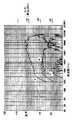
図44は、図42、43Aおよび43Bに示すマイクロホンアセンブリ3600の2つの変換器3602および3604の2つの極感度パターンを示したものである。図44から明らかなように、2つのパターンのヌルは、運転者(約60度)または前部乗員(約300度)のいずれかに向けられている。これは、ポート3626をブロックするかあるいは除去することによって達成され、また、抵抗率の高い風防およびハウジング3610内の比較的小さくかつ狭い音響チャンバを使用することによって促進される。
【0142】
同様の利点を達成するための第2の構成は、図42に示す方法と同じ方法で整列した、第1および第2の変換器3602および3604を備えているが、この実施形態によるマイクロホンアセンブリ3650は、マイクロホンハウジング3660が、差込み式あるいは除去可能な異なるポートを備えている点で異なっている。詳細には、図45Aおよび45Bに示すこの構成では、フロントポート3618aおよび3618bは、差し込まれているかあるいは除去されており、リアポート3626aは開放されている。また、リアポート3626bおよび3624bは、差し込まれているかあるいは除去されている。このようなポート化により、バックミラーアセンブリの回転(マイクロホンアセンブリがバックミラー上に取り付けられる場合)を考慮した非対称ポート構成が生成される。図46は、図45Aおよび45Bに示すハウジング3660内に使用された場合の2つの変換器3602および3604に関連する2つの極パターンを示したものである。
【0143】
特にハウジング後部のいくつかのポートを差し込み、あるいは除去することによる利点の1つは、それにより変換器上の直接空気流がさらにブロックされ、それにより空気流雑音が小さくなることである。
【0144】
図47は、ヌル操作および固有の利点を達成する第3のマイクロホンアセンブリ3700を示したものである。この第3の構造は、マイクロホンハウジング3710(図48Aおよび48B)が、差し込まれた、あるいは除去された前述のポートを全く有していない点が異なっている。その代わりに、第2の変換器3604の前部表面がより直接的に運転者に向くよう、第2の変換器3604を30度回転させることによって極パターンのヌルが向けられている。変換器は、位相差を回避するために互いに近接して配置しなければならず、したがって、変換器のダイヤフラムを約1.27cm(1/2インチ)離して離隔されることが好ましい。
【0145】
図49は、ヌル操作および固有の利点を達成する第4のマイクロホンアセンブリ3750を示したものである。この第4の構造は、第3の構造と同じハウジング3710(図48Aおよび48Bに示す)を利用しているが、第1の変換器3602の後部表面がより直接的に運転者に向き、また、第2の変換器3604の後部表面がより直接的に前部乗員に向くよう、第1および第2の変換器3602および3604がいずれも回転している点で第3の構造と異なっている。各変換器を約25度回転させ、変換器の前部表面と前部表面の間の夾角が約50度になることが好ましいが、ゼロから60度までであれば、各変換器をいずれの角度に回転させても良好な性能を得ることができる。好ましい回転は、車両およびミラーの仮想回転(ミラー上に配置される場合)によって様々である。回転角は、仮想ミラー回転角の2倍であることが最も好ましい。仮想ミラー回転角の典型的な範囲は、10度と25度の間であり、したがって変換器の好ましい典型的な回転角は、20度から50度である。この構造の場合、一方の変換器にヌル角度で入る運転者音声は、その運転者音声成分が極めて小さく、一方、ヌルに対して90度でもう一方の変換器に入る運転者音声は、大まかにオンアクシスより6dB小さいが、依然としてもう一方の変換器のヌルよりはるかに大きい成分を有している。変換器のフロントローブをフロントガラス上の同一ポイントに向けることによって等しい量の雑音が存在し、したがって2つの変換器からの2つの信号を減算することによって雑音が相殺される。
【0146】
図50A〜50Eは、本発明による他の実施形態を示したものである。一般的には、マイクロホンアレイ、ビーム形成および極操作に関連するDSPプロセスは、異なる位置に配置された変換器から得られる信号間の予測可能位相差を利用している。そのためには、プロセスが対処する最高周波数に対して存在する位相差反転に十分に近づけて変換器を配置する必要がある。以下で考察する実施形態には実到達時間が使用されているため、はるかに広い間隔、すなわち全音声帯域幅を超える1つの広い間隔を使用することができる。この実施形態には、位置決定メカニズムとして、2つの変換器の間の極応答の差が使用されている。また、二次概念とは異なり、極応答の差の使用は、間隔には無関係である。この概念を実施することにより、原点および相対振幅に基づいて副帯域を分離することができる。図41A〜41Dを参照して上で開示した実施形態と同様、この実施形態にもゲーティングの概念が使用されている。複数の条件が、信号または信号成分が通過したかどうかを決定している。これは、通過信号を形成するために、加算または減算によってフィルタリングする技法とは対照的である。この実施形態の利点は、ひずみが少なくなること、およびシステムの設計に対する制限が少なくなることである。広義には、本発明のこの実施形態は、高レベルの環境騒音の中から必要な音声信号を抽出している。
【0147】
この実施形態は、非音響雑音がなく、かつ、最新DSPプロセスをサポートするデータを豊富に含んだ信号を供給する2つの電子の耳を効果的に生成している。詳細には、これらの人工耳には、空気流雑音および振動雑音がない。空気流に対する抵抗力は、関係する閾値に対して、取るに足らないフローノイズが生じる程度の抵抗力である。したがって、この実施形態は、DSPのオペレーションに有害な影響を及ぼすことはない。さらに、非音響雑音に対する自由性および極めて重要かつ一貫した位置の存在を使用して、通常、音声品質を貧弱な音声認識性能のポイントまで低下させるだけの十分な役割を果たしている車両条件から、極めて自然な音およびスペクトル成分音声を抽出することができる一連のプロセスを画定している。この実施形態は、車両のバックミラーに設けられる場合、該バックミラーが「自由空間」中に有効に位置付けされ、かつ、最大角度分離が音源の位置と音源の位置との間に存在するように位置付けされる限り、とりわけ良好に機能する。好ましい形態には、雑音到着角度を予測し、かつ、この環境の中で有効に動作するための人工耳の能力を完全無欠にするために、風防の存在など、バックミラー位置の他のアスペクトが使用されている。
【0148】
自動車のアプリケーションにおけるマイクロホンは、通常、マイクロホンを通過して流れる空気により、極めて高い出力を生成している。対照的に、耳には全く空気流感度がない。空気流雑音には、音響雑音に期待されるような関係がないため、空気流雑音は、雑音低減プロセスを妨害している。人工耳は、ミラーハウジング1630の両端に、マイクロホンアセンブリ3802および3804を横方向に離隔されて配置すること(マイクロホンアセンブリは、少なくとも約5cm離れていることが好ましく、約18cm離れていることがより好ましい)、および変換器3820の「D」を、少なくとも約3.5mm、より好ましくは少なくとも10mmまで過剰拡張させることによって達成される。これにより、マイクロホンが利用している可聴周波音センシングの1つの成分に対する極めて高い感度が生成される。より体積の大きい二次後部空洞(図50Eの3826)が生成され、音響抵抗3828が、抵抗3828と変換器3820の後部の間の空洞と共にリアポート3808に配置されている。この空洞3826は、音声センシングメカニズムを拡張し、所望する極特性を達成するために必要な関係を回復している。3828に類似した高音響抵抗カバー3822が、外部前向きポート3806を覆って配置され、ポートを厳重に制動している。両ポートに対するこの厳重な制動が、音響感度および空気流雑音を小さくしている。マイクロホン出力変換に対する優勢振動は、静止空気に対するマイクロホンの振動によって生じるため、振動雑音も小さくなる。最終結果として正規の音響感度が得られ、空気流雑音および振動雑音が著しく低減される。これは、空気流雑音に対する基本的な信号改善であるため、あらゆる方向からのすべての空気流に適用される。マイクロホンアセンブリの「D」を長くしたことにより、ミラーハウジングの後部表面に沿って、対角線に沿って配置され、下部部分が中央に向かって内側に角度が付けられ、また、上部部分が外側に向かって角度が付けられている。その結果、フロントガラスの境界に沿った、バックミラーの下方からの音に対する雑音が著しく低減され、かつ、角度を付けた位置決めにより、2つのマイクロホンアセンブリ間の共通軸に対して一定の角度をなして入ってくる音の大きな差が著しく低減される。
【0149】
過剰に長い「D」を使用することにより、ほとんどの通過帯域の指向性特性が著しく改善される。高い周波数を使用することによって、指向性特性の改善が促進されるとは限らない。この欠損は、前向きポート3806および3812に向けた、部分的に角の形(すなわちラッパ形)の開口3810および3816などの指向性手段を追加することによって対処されている。周波数応答による影響は些細なものであるが、このアスペクトについては、ディジタル化に先立って理想的に実施される電子等化によって補正することができる。
【0150】
バックミラーハウジング1630の両端に同様の構造を設けることにより、空気流雑音のない、優勢空間雑音位置を拒絶する、それぞれ極めて高度の指向性を有し、かつ、それぞれ音源角度位置に対する大きいスペクトル差を提供する目的を有する2つの信号を得ることができる。また、マイクロホンアセンブリ3802および3804の間隔が広いため、大きな到着時間差が存在している。これらの「人工耳」は、コンパニオンDSPアルゴリズムに必要な、不要な空気流雑音および機械雑音のない、あらゆる種類のデータを生成している。したがってDSPアルゴリズムは、追加データを利用し、かつ、非音響雑音成分からの自由を享受することができる。
【0151】
ほとんどのアプリケーションに対する好ましいデフォルトは、音声が検出されるまでDSPに信号を提供させないことである。したがって、好ましいプロセスは、常に信号を通過させるのではなく、音声検出基準に合致するまで信号を通過させないこと、および雑音成分をより小さくする試行に基づいている。そのために処理遅延がもたらされるが、引き渡す信号を若干遅延させることにより、発せられた言葉の未だ使用されていない最初の発声を処理するための補償が得られる。プロセスは、各耳チャネルにおける、音声の発声と一致した入力変化の発生を決定することから開始される。これは、確立したDSPプロセスである。本発明の場合との相異は、このアクションが、2つのチャネル内で、音声に類似した事象を通過させることによってのみ実施されることである。本発明は、音声成分が非常に小さくなり、事実上、役に立たなくなる時間を回避している。よりローバストな音声認識およびより良好な音声品質に対しては、閾値をより高く設定し、あるいは音声状況に対する雑音がより高い場合は、閾値をより低く設定することができる。さらに、到着時間を利用して、所望する空間位置(すなわち、運転者または他の乗員が位置している位置)からの音声のみを処理するプロセスを開始させることができる。妥当ではない到着時間の差が、2つのポート3806および3812の中心軸の周りの音源位置ラインから到着する雑音と場合によっては矛盾する雑音を制限している。また、DSPに記憶されている、所望のユーザおよび日常的な会話者の知識を適用することによって、櫛形通過フィルタを生成するために、ユーザの基本振動数を決定することができる。その結果、音声を含んでいると考えられる帯域のみが存在する。これは、声帯音が支配する帯域においては最も有効である。このポイントにおいては、音声を含んでいると考えられるあらゆる帯域が通過し、適切な位置からの音および音声に極めて類似した音のみが通過する。また、相対スペクトル成分を使用して、位置をさらに分離することができる。あらゆる空間位置に対して、両信号のエントリ角度に対する相対周波数応答をマップすることができる。必要なことは、音声帯域が存在する領域にアドレスすることだけである。マイクロホンアセンブリ3802および3804からの2つの信号のスペクトル成分の差を比較することにより、DSPは、現行の優勢信号が焦点の合った位置からの信号であるかどうかを決定することができる。より有用なことに、DSPは、通過した帯域中の時間変化帯域が、焦点の合った位置以外の他の位置から発信されたものであるかどうかを決定することができる。これは、相対振幅と応答マップを比較することによって達成される。例えば、左右の差が+3dBであり、また、差が−2dBである場合、DSPは、この特定の帯域が焦点の合った空間位置から発信されたものではないことを知り、除去することができる。このポイントにおいては、所望の位置からの音声音のみが通過している。この時点で、DSPの目標ユーザの知識を使用して、ミッシング音声帯域を再構築することができる。詳細には、重要な音声成分が存在する帯域が存在することになるが、音声成分は、有効と見なされるほど十分な大きさではなく、フィルタリングプロセスで失われることになる。人間は、雑音の少ない時間から、会話者の音がどのようなものであるかを知り、極めて雑音の高い状態の間、その知識を適用することによって音声帯域を推定している。DSPは、同一形態の処理を使用することができる。詳細には、DSPは、観察した基本振動数領域に対する高調波振幅マップを常に生成することができる。基本振動数が分かれば、その基本振動数をマップ基準として使用し、高調波の相対振幅を抽出することができる。すべての人間は一貫した高調波マップを有しているため、固定頭部空洞の結果、DSPは、既知の高調波振幅を適用することにより、ミッシング音声帯域を推定することができる。例えば、人間の音声は、極めて高い雑音環境の中では、一般的にその高周波成分を失う。高帯域のいくつかが失われることのない、雑音のより少ない環境では、その音声に関する知識を得ることができ、その知識を使用して、より高い雑音環境中でミッシング帯域を充填することができる。
【0152】
使用されるフィルタのシーケンスおよび数は、必要性、利点およびコストに応じて様々である。人工耳から引き出される豊富なデータおよび会話者の知識を利用する主要な目的は、高い雑音による有害な影響のない音声をもたらすことである。図50A〜50Eを参照すると、2つのマイクロホンアセンブリ3802および3804がミラーハウジング1630の後部に統合され、これらのアセンブリ中に設けられている変換器の中心軸が、互いに対して、かつ、ミラー表面に対する垂線に対して一定の角度になるように配置されている。また、変換器の中心軸は、一定の角度で運転者の位置に対して上向きに向けられている。これにより、マイクロホンアセンブリをミラーアセンブリのより後部に統合することができ、かつ、運転者または他の乗員の視界から幾分そらせることができる。
【0153】
上記実施形態は、広帯域を基本として、自動車の環境における問題に対処しているが、使用されている変換器は全方向性であり、また、DSPは、より低い周波数帯域に対しては到着時間を利用し、一方、より高い周波数帯域に対しては、前向きポート部分のホーンによって提供される指向性特性を使用している。
【0154】
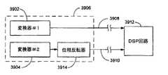
マイクロホンアセンブリ3900が、関連するDSP回路3912(図51)から離れた車両中に配置される場合、含有雑音は、通常、マイクロホンアセンブリからDSP回路に延びている電気導線3908上に存在することになる。この雑音を除去するために、基準ライン3901が、同じくマイクロホンアセンブリの位置からDSP回路まで通っている。基準ライン3901のマイクロホン側の端部にインピーダンス整合回路3903が設けられており、マイクロホン変換器3902のインピーダンスを整合させている。この基準ライン上には含有雑音のみが存在するため、この含有雑音が検出され、マイクロホンアセンブリから引き渡される信号から控除される。1つまたは複数のマイクロホンアセンブリから複数の信号がDSP回路に引き渡される場合、車両を通して布線しなければならないラインの数は、その整数倍に対応することになる。例えば、2つのマイクロホン変換器を利用した、対応する2つの出力信号をDSP回路に引き渡さなければならないシステムの場合、2本ではないとしても、少なくとも1本の基準ラインが必要である。車両を通って延びるこれらの電気導線の追加は、すべてこのようなシステムのコストに大きく反映される。したがって、遠隔DSP回路まで布線する必要のある電気導線の本数を最少化しつつ、複数の変換器の利用を可能にするシステムが必要である。
【0155】
上記システムにおける基準ラインの必要性を排除するために、図52に示すような回路を利用することができる。詳細には、ミラーアセンブリ3906内に設けられた2つの変換器3902および3904の各出力ライン3908および3910が、マイクロホン変換器が取り付けられているバックミラーアセンブリまたは他の車両アクセサリから離れて配置されたDSP回路3912に提供されている。2つの変換器のいずれか一方がセンスした音響信号の位相を反転させるために、ライン3908および3910のいずれか一方の経路内に位相反転器3914が設けられている。DSP回路3912には、この特定の変換器からの可聴信号が反転されていることが予め分かっており、したがってそれに応じた処理を実行するが、ミラーアセンブリとDSP回路の間の2本のラインに誘導される雑音は反転されないため、DSP回路は、可聴信号とライン3908および3910の両方に共通の雑音とを区別することができる。明らかに近接して配置される2つのマイクロホン変換器の間には、到着時間の差あるいは位相の差がほとんどないため、相殺プロセスによって失われる運転者音声成分は、あるとしても極めて僅かである。失われる音響成分は雑音か、あるいは出力中に大きな位相差をもたらすように到着する他の音のみである。DSPは、別法として、第2の信号の位相を再反転した後、互いに位相が外れた共通信号に基づいて、可聴信号とライン誘導雑音とを区別することもできる。
【0156】
上で説明したマイクロホンアセンブリは、車両内部のどこにでも組み込むことができる。例えば、マイクロホンアセンブリは、車両の内部トリム、オーバヘッドコンソール、バイザ、バックミラーアセンブリおよびエレクトロニック・リアビジョンディスプレイのハウジングの内部、あるいはフロントガラス上のバックミラー取付け構造の近傍に設けられたミニオーバヘッドコンソールの内部に配置することができる。好ましい実施形態では、マイクロホンアセンブリは、自動車のバックミラーアセンブリの内部またはバックミラーアセンブリの上に組み込まれている。必要に応じて、連続性の改善を容易にするために、マイクロホンアセンブリを電子アセンブリに結合しているコネクタの接点を貴金属(例えば、金または銀)でめっきすることができる。
【0157】
以上、車両用改良型マイクロホンアセンブリを開示した。このマイクロホンアセンブリは、広範囲の様々な性能アプリケーションへの適用が意図されており、マイクロホンアセンブリは、単一または複数の変換器を備えることができる。複数の変換器を使用することにより、性能が著しく改善される。それほど高い性能を必要としないアプリケーションでは、所望の指向性パターンを達成するために、適切にポート化された単一または複数のダイヤフラムを有する1つの変換器を使用することにより、複数の変換器を有するマイクロホンアセンブリと同じマウントおよびハウジングに使用することができる、より低コストのマイクロホンが提供される。
【0158】
本発明について、本明細書においては、本発明の特定の実施形態に従って詳細に説明したが、当分野の技術者には、本発明の精神を逸脱することなく、多くの改変および変更を実施することができる。したがって、本発明は、特許請求の範囲の各請求項の範囲によってのみ制限されるものであり、本明細書において示した実施形態を説明した詳細および手段によって制限されるものではない。
【図面の簡単な説明】
【0159】
【図1】屋根の一部を切り欠いて示す車両の平面図である。
【図2】図1に示す車両に使用されているバックミラーアセンブリおよび断片的ミラーサポートを示す前部、底部および左側面の斜視図である。
【図3】図2に示すミラーに使用されているマイクロホンアセンブリの平面分解図である。
【図4】図3に示すミラーアセンブリの底面図である。
【図5】図3に示すマイクロホンアセンブリ中の変換器マウントの底面図である。
【図6】図3に示すマイクロホンアセンブリを示す、図4の平面6−6に沿って取った横断面図である。
【図7】変換器マウント中の変換器を示す、回路基板が除去された図5のマイクロホンアセンブリの平面図である。
【図8】図3〜7に示すマイクロホンアセンブリに使用される回路を、一部ブロック図の形で示す略回路図である。
【図9】図1〜7に示すマイクロホンアセンブリの変換器の音響チャネルを示す略平面図である。
【図10】マイクロホンアセンブリの代替変換器構造の音響チャネルを示す略平面図である。
【図11】マイクロホンアセンブリの他の代替変換器構造の音響チャネルを示す略平面図である。
【図12】請求項11に記載のマイクロホンと共に使用される回路を、一部ブロック図の形で示す略回路図である。
【図13】マイクロホンアセンブリと共に使用される自動較正回路を、一部ブロック図の形で示す略回路図である。
【図14】図12に示すコントローラの動作を示す流れ図である。
【図15】マイクロホンの縦軸に沿って取った、図10に示すマイクロホンの横断面図である。
【図16】本発明の他の実施形態に従って構築されたマイクロホンアセンブリの斜視図である。
【図17】図16に示すマイクロホンアセンブリの分解斜視図である。
【図18】本発明の他の実施形態に従って構築されたバックミラーアセンブリの実施形態の正面等角図である。
【図19】図18に示すバックミラーアセンブリの実施形態の背面等角図である。
【図20】図18および19に示すバックミラーアセンブリの側面図である。
【図21】本発明の他の実施形態に従って構築されたマイクロホンアセンブリの分解斜視図である。
【図22−A】本発明に従って構築された、変換器を覆うカバーを備えたマイクロホンアセンブリによって得られる、異なる周波数における極パターンをプロットしたグラフである。
【図22−B】本発明に従って構築された、変換器を覆うカバーを備えたマイクロホンアセンブリによって得られる、異なる周波数における極パターンをプロットした他のグラフである。
【図22−C】本発明に従って構築された、変換器を覆うカバーを備えたマイクロホンアセンブリによって得られる、異なる周波数における極パターンをプロットした他のグラフである。
【図22−D】本発明に従って構築された、変換器を覆うカバーを備えたマイクロホンアセンブリによって得られる、異なる周波数における極パターンをプロットした他のグラフである。
【図23−A】本発明に従って構築された、変換器を覆うカバーのないマイクロホンアセンブリによって得られる、異なる周波数における極パターンをプロットしたグラフである。
【図23−B】本発明に従って構築された、変換器を覆うカバーのないマイクロホンアセンブリによって得られる、異なる周波数における極パターンをプロットした他のグラフである。
【図23−C】本発明に従って構築された、変換器を覆うカバーのないマイクロホンアセンブリによって得られる、異なる周波数における極パターンをプロットした他のグラフである。
【図23−D】本発明に従って構築された、変換器を覆うカバーのないマイクロホンアセンブリによって得られる、異なる周波数における極パターンをプロットした他のグラフである。
【図24】本発明の他の実施形態によるデフレクタ、微小乱流発生器およびマイクロホンアセンブリを有するバックミラーアセンブリの一部を示す側面図である。
【図25】図24に示すデフレクタ、微小乱流発生器およびマイクロホンアセンブリを有するバックミラーアセンブリの一部を示す平面図である。
【図26】図24および25に示すデフレクタ、微小乱流発生器およびマイクロホンアセンブリを有するバックミラーアセンブリの一部を示す背面図である。
【図27】本発明によるマイクロホン処理回路の実施形態をブロック図の形で示す電気回路図である。
【図28−A】図27に示す回路に使用される例示的広域通過フィルタを略図の形で示す電気回路図である。
【図28−B】図27に示す回路に使用される例示的全域通過移相器を略図の形で示す電気回路図である。
【図28−C】図27に示す回路に使用される例示的加算回路を略図の形で示す電気回路図である。
【図28−D】図27に示す回路に使用される例示的3極広域通過フィルタを略図の形で示す電気回路図である。
【図28−E】図27に示す回路に使用される例示的バッファ回路を略図の形で示す電気回路図である。
【図29−A】3つの異なる方向から発信される音声に対する二次マイクロホンアセンブリの3つの周波数応答曲線をプロットしたグラフである。
【図29−B】図27に示す、全域通過移相器を持たない二次マイクロホン処理回路の周波数応答曲線をプロットしたグラフである。
【図29−C】4つの異なる方向から発信される音声に対する、図27に示す二次マイクロホン処理回路の4つの周波数応答曲線をプロットしたグラフである。
【図30】本発明に従って構築されたマイクロホンシステムのブロック図である。
【図31】図30に示すディジタル信号プロセッサのための第1の実施形態によるプロセス線図である。
【図32】雑音およびユーザの音声の両方を受け取っている間に、典型的な変換器から受け取る可聴信号のFFTの例示的プロットを示すグラフである。
【図33】図32にそのFFTを示す可聴信号をフィルタリングするための理想的反転櫛形フィルタを示すグラフである。
【図34】図30に示すディジタル信号プロセッサのための第2の実施形態によるプロセス線図である。
【図35】電子アセンブリに結合された従来技術によるマイクロホンアセンブリの簡易電気図である。
【図36】本発明の一実施形態によるマイクロホンインターフェースを介して電子アセンブリに結合されたマイクロホンアセンブリの簡易電気図である。
【図37】本発明の他の実施形態によるマイクロホンインターフェースを介して電子アセンブリに結合されたマイクロホンアセンブリの簡易電気図である。
【図38】本発明のさらに他の実施形態によるマイクロホンインターフェースを介して電子アセンブリに結合されたマイクロホンアセンブリの簡易電気図である。
【図39−A】本発明の代替実施形態に従って構築されたバックミラーアセンブリの前面の正面図である。
【図39−B】図39Aに示すバックミラーアセンブリの背面の正面図である。
【図39−C】図39Aおよび39Bに示すバックミラーアセンブリの側面の正面図である。
【図39−D】図39A〜39Cに示すバックミラーアセンブリの頂部の平面図である。
【図40】車両デフロスタを最高速度で運転した場合の、様々なマイクロホンアセンブリの出力を表す4つのプロットを示すグラフである。
【図41−A】本発明の他の実施形態によるマイクロホンアセンブリを組み込んだバックミラーの斜視図である。
【図41−B】本発明の他の実施形態によるマイクロホンアセンブリを組み込んだバックミラーの他の斜視図である。
【図41−C】本発明の他の実施形態によるマイクロホンアセンブリを組み込んだバックミラーの他の斜視図である。
【図41−D】本発明の他の実施形態によるマイクロホンアセンブリを組み込んだバックミラーの他の斜視図である。
【図42】ハウジングの概略と共に示す、本発明によるマイクロホンアセンブリの他の実施形態の頂部の平面図である。
【図43】図43Aは、図42に示す本発明の実施形態に従って構築されたマイクロホンアセンブリに使用されるハウジングの斜視図である。 図43Bは、図42に示す本発明の実施形態に従って構築されたマイクロホンアセンブリに使用されるハウジングの他の斜視図である。
【図44】図42、43Aおよび43Bに示す本発明の実施形態に従って構築されたマイクロホンアセンブリによって得られる、2つの変換器の両方の極パターンをプロットしたグラフである。
【図45】図45Aは、図42に示す本発明の実施形態に従って構築されたマイクロホンアセンブリに使用される代替ハウジングの斜視図である。 図45Bは、図42に示す本発明の実施形態に従って構築されたマイクロホンアセンブリに使用される代替ハウジングの他の斜視図である。
【図46】図42、45Aおよび45Bに示す本発明の実施形態に従って構築されたマイクロホンアセンブリによって得られる、2つの変換器の両方の極パターンをプロットしたグラフである。
【図47】ハウジングの概略と共に示す、本発明によるマイクロホンアセンブリの他の実施形態の頂部の平面図である。
【図48】図48Aは、図47および49に示す本発明の実施形態に従って構築されたマイクロホンアセンブリに使用されるハウジングの斜視図である。 図48B、図47および49に示す本発明の実施形態に従って構築されたマイクロホンアセンブリに使用されるハウジングの他の斜視図である。
【図49】ハウジングの概略と共に示す、本発明によるマイクロホンアセンブリの他の実施形態の頂部の平面図である。
【図50−A】本発明の他の実施形態によるマイクロホンアセンブリを組み込んだバックミラーアセンブリを示す図である。
【図50−B】本発明の他の実施形態によるマイクロホンアセンブリを組み込んだバックミラーアセンブリを示す他の図である。
【図50−C】本発明の他の実施形態によるマイクロホンアセンブリを組み込んだバックミラーアセンブリを示す他の図である。
【図50−D】本発明の他の実施形態によるマイクロホンアセンブリを組み込んだバックミラーアセンブリを示す他の図である。
【図50−E】本発明の他の実施形態によるマイクロホンアセンブリを組み込んだバックミラーアセンブリを示す他の図である。
【図51】本発明と共に使用される雑音相殺回路をブロック図の形で示す電気回路図である。
【図52】本発明と共に使用される代替雑音相殺回路をブロック図の形で示す電気回路図である。【Technical field】
[0001]
The present invention relates to microphones, and more particularly, to microphones coupled to vehicle accessories, such as rearview mirror assemblies or housings for rear vision display devices.
[Background Art]
[0002]
It has long been desired to improve the performance of microphones in devices such as communication devices and voice recognition devices that operate under a wide variety of environmental noise conditions. Communication devices that support hands-free operation allow a user to communicate through the device microphone without using hands. Due to the separation between the user and the microphone, these microphones often detect unwanted noise in addition to the user's voice. It is difficult to attenuate noise. In the case of a hands-free communication system for a vehicle, it is particularly difficult because the existing environmental noise changes dynamically. For example, vehicles such as automobiles, trains, aircraft, and boats use two-way communication systems such as two-way wireless, cellular telephone, and satellite telephone. For various reasons, the communication devices in these systems are hand-free so that the user does not need to hold the device during a conversation, even in the presence of high levels of dynamically fluctuating environmental noise. It is preferable to operate with.
[0003]
The two-way communication system includes an audio speaker and a microphone. In order to improve the hands-free performance of vehicle communication systems, microphones are usually mounted near the driver's head. For example, microphones are typically attached to a vehicle visor or headliner using fasteners such as clips, adhesives, hook and loop fastening tapes (such as VELCRO® brand fasteners). The audio speaker coupled to the communication system is preferably positioned away from the microphone to help minimize feedback from the audio speaker to the microphone. For example, audio speakers are typically located in vehicle adapters such as hang-up cups or cigarette lighter plugs used to supply power from the vehicle electrical system to the communication device. Therefore, the position of the audio speaker is known to the designer of the communication system in advance, but the position of the microphone is unknown to the designer because the user can select the position. The position of the microphone relative to the talker determines the level of the audio signal output from the microphone, and the position of the microphone relative to the individual affects the signal-to-noise ratio. Also, the position of the microphone with respect to the audio speaker affects the feedback between the speaker and the microphone. Therefore, the performance of the acoustic system changes depending on the installation of the microphone by the user. Also, microphones typically include aesthetically undesirable wires when mounted on the inside surface of the vehicle. Also, if the wire is attached to the back of the inner lining, the inside of the vehicle must be dismantled and reattached so that the wire is hidden, so that the parts may make a loud noise and This causes the frame to hang loosely.
[0004]
One possible solution to avoid these difficulties is the "REAVIEW MIROR AND ACCESSORY MOUNT FOR VEHICLES" issued to Schofield et al. On June 5, 1990, with a microphone mounted during mirror mounting support. No. 4,930,742. The placement of the microphone in the mirror support provides a known microphone position to the system designer and avoids the problems associated with mounting the microphone after the vehicle has been manufactured, but such structures have many disadvantages. There are disadvantages. The placement of the mirror between the microphone and the individual speaking into the microphone eliminates a direct unobstructed path from the user to the microphone. Also, the position of the microphone on the windshield has a detrimental effect on the flexibility of the microphone design and the overall noise performance of the microphone.
[0005]
U.S. Pat. Nos. 5,940,503, 6,026,162, 5,566,224, 5,878,353 and D402,905 have a microphone mounted in the bezel of the mirror. Although a rearview mirror assembly is disclosed, none of these patents discloses the use of a multi-directionally facing acoustic port and also discloses a microphone assembly utilizing multiple microphone transducers. There is no. The disclosed microphone assembly does not incorporate sufficient noise suppression components to provide an output signal having a relatively high signal-to-noise ratio, and is directed forward of a directional sensitivity pattern or housing. It does not provide a microphone that has a main lobe and thereby attenuates signals emitted from the sides of the housing.
[0006]
It would be highly desirable to provide a speech recognition system coupled with a vehicle communication system, and most preferably such a system would enable hands-free operation. Hands-free operation of devices used in speech recognition systems is a particularly challenging application for microphones, as the accuracy of the speech recognition system depends on the quality of the electrical signals representing the user's speech. For conventional hands-free microphones, to provide the consistent and predictable microphone performance required for such applications in controlled environments such as offices, as well as uncontrolled noise environments such as cars. Can not.
[Patent Document 1]
U.S. Pat. No. 4,930,742
[Patent Document 2]
US Patent No. 5,940,503
[Patent Document 3]
US Patent No. 6,026,162
[Patent Document 4]
US Patent No. 5,566,224
[Patent Document 5]
U.S. Pat. No. 5,878,353
DISCLOSURE OF THE INVENTION
[Problems to be solved by the invention]
[0007]
Therefore, there is a need for a vehicle microphone with improved hands-free performance, preferably enabling speech recognition operations.
[Means for Solving the Problems]
[0008]
According to a first embodiment of the present invention, a microphone system comprises a microphone assembly comprising a first transducer for generating a first audible signal and a second transducer for generating a second audible signal; A remote processing circuit located remote from the microphone assembly; and a microphone interface circuit electrically coupled between the transducer and the remote processing circuit. The microphone interface circuit has a first electrical signal path extending between the first transducer and the remote processing circuit, and a second electrical signal path extending between the second transducer and the remote processing circuit. , The second electrical signal path includes a phase inverter circuit provided in the vicinity of the second converter for inverting the phase of the second audible signal. The remote processing circuit is adapted to recognize that the phase of the second audio signal has been inverted and to process the second audio signal based thereon. The remote processing circuit also recognizes a common signal on both the first and second electrical signal paths as line induced noise.
[0009]
According to another embodiment of the present invention, a vehicle accessory includes a housing for mounting on a vehicle, a first transducer for generating a first audible signal, and a second transducer for generating a second audible signal supported by the housing. And a microphone interface circuit electrically coupled between the transducer and a remote processing circuit located remotely from the microphone assembly. The microphone interface circuit has a first electrical signal path extending between the first transducer and the remote processing circuit, and a second electrical signal path extending between the second transducer and the remote processing circuit. , The second electrical signal path includes a phase inverter circuit provided in the vicinity of the second converter for inverting the phase of the second audible signal.
[0010]
According to another embodiment of the present invention, a vehicle accessory includes a housing for mounting on a vehicle, a microphone assembly for generating an audible signal supported by the housing and including at least one transducer, and a transducer. And a microphone interface circuit electrically coupled between a remote processing circuit located remotely from the microphone assembly. The microphone interface circuit includes: a first electrical signal path extending between the transducer and the remote processing circuit; an impedance matching circuit for providing a grounded electrical connection that is impedance matched to the impedance of the transducer; A second electrical signal path extending between remote processing circuits adjacent to the signal path. The second electrical signal path includes a line induced noise from the first electrical signal path, wherein the remote processing circuit subtracts a noise signal received from the second electrical signal path from a signal received from the first electrical signal path. To provide a reference to the remote processing circuitry for the line induced noise present on the first signal path.
[0011]
According to another embodiment of the present invention, a vehicle accessory includes an accessory housing for mounting on a vehicle, and a microphone assembly supported by the accessory housing. The microphone assembly has a microphone housing having a plurality of ports with a draft shield over its entire surface, a first transducer for generating a first audible signal disposed within the microphone housing, and disposed within the microphone housing. , A second converter for generating a second audible signal. The front face of the second transducer faces in a direction different from the direction of the front face of the first transducer. The ports, draft shield and transducer are such that the microphone assembly shows a first pole pattern with nulls directed to the driver of the vehicle and a second pole pattern with nulls directed to the front occupant region of the vehicle. It is configured.
[0012]
According to another embodiment of the present invention, a vehicle accessory comprises: an accessory housing for mounting on a vehicle; a microphone assembly comprising at least one transducer for providing an audible signal supported by the accessory housing; A high frequency boost circuit for receiving an audible signal and for boosting the high frequency response to compensate for the effect of the vehicle on the frequency response of the microphone assembly.
[0013]
According to another embodiment of the present invention, a vehicle accessory includes an accessory housing for mounting on a vehicle, a first microphone assembly supported by the accessory housing, and a location laterally spaced from the first microphone assembly. And a second microphone assembly supported by the accessory housing. The first and second microphone assemblies have a "D" of at least about 3.5 mm.
[0014]
In accordance with another embodiment of the present invention, a vehicle accessory includes a housing for mounting to a vehicle, a microphone assembly with a windshield supported by the housing, and an air source disposed on the housing near the microphone assembly. A cross deflector for deflecting the flow from the microphone assembly.
[0015]
According to another embodiment of the present invention, a vehicle accessory includes a housing for mounting to a vehicle, a first transducer supported by the housing, and a first transducer laterally coupled to the first transducer supported by the housing. A second transducer spaced apart and airflow from the side of the first transducer, located between the first transducer and the second transducer, physically separated from the second transducer; A separator for deflecting and physically deflecting the airflow from the side of the second transducer from the first transducer.
[0016]
According to another embodiment of the present invention, a vehicular rearview mirror assembly includes a mirror housing for mounting on a vehicle, a mirror having a front surface disposed within the mirror housing, and a second mirror supported by the mirror housing. One microphone housing, first and second transducers located within the first microphone housing, a second microphone housing supported by the mirror housing, and a second microphone housing located within the second microphone housing. Third and fourth converters. The first microphone housing is located closer to the front surface of the mirror than the second microphone housing. The second and fourth transducers are adapted to compensate for frequency differences due to the proximity of the first microphone housing to the front surface of the mirror. A pole pattern associated with the housing is provided for each change.
[0017]
These and other features, advantages and objects of the present invention will become more fully understood by those skilled in the art by reference to the following specification, claims, and accompanying drawings. And will be recognized.
[0018]
The subject matter which is regarded as the invention is particularly pointed out and distinctly claimed in the concluding claims of the specification. The invention, together with other objects and advantages of the invention, will be best understood by referring to the following description taken in conjunction with the accompanying drawings. Like numbers in the accompanying drawings represent like components.
BEST MODE FOR CARRYING OUT THE INVENTION
[0019]
The microphone assembly according to the present invention is coupled to the internal rearview mirror and performs well in the presence of noise. The microphone assembly according to the invention improves the signal-to-noise ratio of the output of the microphone assembly, so that these microphone assemblies can be combined for hands-free applications, for example for sensitive applications such as speech recognition for telecommunication systems. The performance of the device is enhanced. The microphone assembly according to the present invention eliminates mechanically induced noise and provides the designer with significant flexibility regarding microphone assembly sensitivity, frequency response and pole pattern selection. A circuit is also provided for the converter to generate an audible signal from the converter output having a high signal-to-noise ratio.
[0020]
The vehicle 100 (FIG. 1) includes an internal rearview mirror assembly 101 that allows a vehicle operator 103 (shown in phantom lines) to overlook a portion of the road behind the
[0021]
FIG. 2 is an enlarged view of the rearview mirror assembly 101 according to the first embodiment. Mirror assembly 101 includes an elongated housing 206 pivotally supported by mirror support 104. The mirror 202 may be a prism mirror of the type used with a mirror housing that allows for manual adjustment of day and night operation, or an automatically adjusted reflectivity, such as an electro-optic or electrochromic mirror. It can be any conventional internal rearview mirror, such as a multiple element mirror. Elongated housing 206 may be made of any conventional product, such as a one-piece plastic product.
[0022]
The rearview mirror assembly 101 is also preferably mounted to the housing 206 at a location visible to the driver 103 of the vehicle, ie, at a specific location that is a direct visual axis between the talker's mouth and the microphone. 208. Microphone assembly 208 is advantageously located on mirror housing 206 because the mirror assembly is movably supported on support 104. Driver 103 (FIG. 1) typically adjusts the position of mirror 202 and housing 206 so that the reflected image can be viewed through rear window 109 of
[0023]
Next, a first embodiment of the microphone assembly 208 will be described in greater detail with reference to FIGS. The microphone assembly includes a
[0024]
The transducer mount 302 is configured to be pushed into the
[0025]
Preferably,
[0026]
[0027]
To assemble microphone assembly 208,
[0028]
The subassembly consisting of the mount 302, the
[0029]
In particular, the front opening 502 of the transducer 306 is connected to the front port 312 of the
[0030]
As shown in FIG. 6, the central axis C of
[0031]
[0032]
The output of the
[0033]
In summary, since the signals from the front of the mirror are summed by the
[0034]
FIG. 9 schematically illustrates the bidirectional microphone assembly 208, and FIGS. 10 and 11 schematically illustrate alternative embodiments thereof. As explained above, the bidirectional microphone assembly 208 has a front opening directed to the front port 312 via channel 506 and a rear opening directed to the back port 314 via
[0035]
The
[0036]
The bidirectional microphone assembly 208 requires a matched transducer to cancel noise, while the hyper-cardioid requires a transducer that produces different on-axis sensitivities. . In particular, the required difference in converter sensitivity for converters 1002 and 1008 is between 5 dB and 15 dB, for example 10 dB. The transducer control and brake valves that must be considered for the hyper-
[0037]
FIG. 11 discloses a secondary microphone assembly 1100 according to another alternative embodiment. Microphone assembly 1100 includes
[0038]
[0039]
In operation, a signal emitted from the front of the microphone assembly 1100 reaches the
[0040]
One of the problems with this embodiment is the possible phase shift. In particular, the higher the frequency, the greater the phase shift that occurs in the signal between the front and rear transducers. A low frequency signal has a small phase shift, and a high frequency signal has a large phase shift. The acoustic sensitivity increases with increasing phase shift, so the low frequency sensitivity is extremely small. However, since the target signal is an audio signal having a relatively high frequency, the influence of this phase shift is not so significant. It is also intended to use equalization techniques to compensate for phase shifts and low frequency roll-offs of the bass sensitivity of microphone 1100. The front and
[0041]
As shown in the microphone assembly 1100 of FIG. 11, the use of four transducers provides the vibration null and additional acoustic benefits of the microphone 208 of the
[0042]
An automatic balancing circuit 1300 (FIG. 13) can be used in place of, or in addition to, the manual balancing potentiometer R8. The auto-balancing circuit includes a
[0043]
In operation, the controller monitors the level of the signal output by
[0044]
[0045]
16 and 17 show alternative structures for the microphone subassembly 1600. As shown, the microphone subassembly 1600 includes an electronic portion 1641 with a first microphone transducer 1642 and a second microphone transducer 1644 mounted on a printed circuit board 1645.
[0046]
The microphone transducers 1642 and 1644 are mounted facing each other or facing each other, and their central axes are coaxially aligned. By mounting the microphones 1642 and 1644 in opposite directions, the sense pressure waves caused by the vibrations are sensed 180 degrees out of phase with each other. Mounting the microphone subassembly to the vehicle such that the common center axis of the transducer and the driver's mouth are substantially aligned, while increasing the driver's voice gain, while increasing the vehicle's
[0047]
As shown in FIG. 17, transducers 1642 and 1644 are mounted with the transducer side up, and the subassembly includes an acoustic port at 90 degrees to the mechanical axis of the transducer. This allows both the natural transducer front port to face the front port whose assembly orientation has been changed.
[0048]
According to another embodiment, the microphone assembly of the present invention utilizes two microphone transducers that are facing away from each other. The output of the backward converter preferentially receives the noise signal, and the output of the forward converter preferentially receives the audio signal. Appropriate electronic processing can determine the presence of a valid audio signal. During periods when no valid audio signal is present, the output is reduced without degrading the audio quality.
[0049]
When this processing is performed based on the frequency band, the frequency band including the effective audio signal can be delivered to the output without any change, so that the band in which noise is dominant is reduced without lowering the audio quality. Can be removed.
[0050]
Microphone transducers 1642 and 1644 are mounted sideways through holes drilled in printed circuit board 1645. Some of the transducers 1642 and 1644 extend below the bottom surface of the circuit board 1645, and some of the transducers 1642 and 1644 extend above the top surface of the printed circuit board 1645. Mounting the transducer in this position, in this orientation relative to the circuit board, offers several advantages. A first advantage is that the electrical contacts of the transducer can be soldered directly to the traces on the printed circuit board. This avoids having to manually connect the wires to the contacts of the transducer and subsequently connecting these wires to the circuit board. Therefore, the converter can be mounted on the circuit board using a conventional circuit board mounting device.
[0051]
Another advantage of mounting the transducer to extend above and below the surface of the printed circuit board is that one side of the circuit board can have a conductive layer that functions as a ground plane. Such a ground plane can shield the transducer from electromagnetic interference (EMI) that can be created by other components within the rearview mirror assembly or other components inside the vehicle. This EMI allows effective noise to be introduced into the signal delivered by the converter. In a preferred embodiment, each of the transducers is mounted on a circuit board having a conductive ground plane on one side facing the acoustically active portion of the transducer and an opposite side on which circuit components are mounted.
[0052]
As shown in FIGS. 16 and 17, the microphone subassembly 1600 further includes a pair of central recesses extending below the bottom surface of the printed circuit board 1645 and adapted to receive a portion of the microphones 1642 and 1644, respectively. An acoustic cup 1650 having 1652 and 1654 is provided. Microphone subassembly 1600 further includes a plurality of ports 1655 disposed around a bottom portion of acoustic cup 1650.
[0053]
The microphone subassembly 1600 further includes a cloth 1658 that serves as a windshield and protects the microphone from the external environment. Cloth 1658 is preferably made of a hydrophobic material and is secured to cup 1650 over port 1665 to prevent moisture from reaching microphones 1642 and 1644.
[0054]
Microphone subassembly 1600 also includes an external microphone housing 1660 formed in the shape of a cup, with a plurality of acoustic ports 1665 disposed around the bottom and sides of the housing. Port 1665 is preferably aligned with port 1655 of acoustic cup 1650. Housing 1660 preferably includes one or more posts 1666a-1666c that align and mate with grooves 1656a-1656c of acoustic cup 1650 and grooves 1646a-1646c of printed circuit board 1645. The posts and grooves serve to align the ports 1655 and 1665 and to prevent rotation or orientation change of the microphone transducer within the housing 1660. Housing 1660 further includes a plurality of tabs 1662a-1662c that resiliently engage a peripheral edge of an opening formed in mirror housing 206 (FIG. 2). The mirror housing 206 preferably has corresponding slots that receive the resilient tabs 1662a-1662c, thereby ensuring optimal alignment of the microphones 1642 and 1644 with respect to the vehicle.
[0055]
Although FIG. 2 shows the microphone subassembly mounted on the bottom of the mirror housing, it should be noted that the preferred location is actually at the top of the mirror housing. FIGS. 18-20 illustrate an embodiment of a rearview mirror assembly in which the microphone subassembly 1600 is mounted on top of a mirror housing. The microphone subassembly mounted on the mirror housing receives not only direct sound from the driver but also sound reflected from the windshield. The time difference between the arrival of the direct sound and the reflected sound when the microphone subassembly is mounted on the bottom of the mirror housing is greater than the time difference when the microphone subassembly is mounted on the top of the mirror housing. If the differences in arrival times are far apart, their combination produces a frequency response with a series of frequencies without power. A plot of this series of frequencies resembles a comb, and is therefore often referred to as the "comb effect".
[0056]
By mounting the microphone subassembly on top of the mirror housing, comb effects in the desired passband are avoided. As shown in the side view of FIG. 20, the distance between the windshield and the top of the mirror housing is much shorter than the distance between the windshield and the bottom of the mirror housing, so that the reflected sound is properly added to the direct sound. , Otherwise, a larger version of the direct sound is produced, resulting in a higher signal-to-noise ratio and better timbre quality. These are very important attributes in hands-free telephone and voice recognition in a vehicle environment.
[0057]
One of the problems associated with mounting the microphone subassembly on top of the mirror housing is due to the microphone assembly being closer to the windshield. When the windshield defroster is activated, the entire surface of the air moves upward along the windshield. Thus, when the microphone subassembly is placed on top of the mirror housing, the microphone subassembly is exposed to more airflow as air from the defroster passes between the mirror housing and the window past the microphone subassembly. Will be. As it passes through the microphone subassembly, the air flow creates turbulence, which produces an effective amount of noise. To solve this problem, a deflector 1670 is deployed upward from the rear of the mirror housing 1630 so that airflow from the defroster is smooth along the top and / or sides of the microphone subassembly 1600. It will not be deflected and therefore the air flow will affect the transducer or create any turbulence as the air flow passes over and around the microphone subassembly. Since the airflow mainly flows into the rear of the microphone subassembly, the deflector is designed to deflect the direction of air flow and to have a minimal effect on the frequency response of the microphone subassembly. This is important for high intelligibility in an automotive environment. Mounting the microphone subassembly on top of the mirror housing provides excellent resistance to noise caused by airflow, since there is no direct effect of air on the microphone subassembly and turbulence near the microphone subassembly is avoided. Power is provided.
[0058]
As an additional measure, a signal indicating that the windshield defroster has been activated may be transmitted via a vehicle bus or other individual wire or wireless communication link. This signal is received and processed by the microphone processor and is used to subtract an exemplary noise waveform corresponding to the noise waveform detected when the windshield defroster is activated. Alternatively, if the driver is speaking into the microphone and the system determines that the windshield defroster has been activated, the system may temporarily turn the defroster down or off. Alternatively, a synthetic voice signal can be generated to urge the driver to turn down the defroster. Recognize the noise generated by the defroster by using a voice recognition circuit inside the mirror so that the system can prompt the driver to turn down or turn off the defroster or perform the task automatically. You can also.
[0059]
In addition to recognizing the sound generated by the windshield defroster, the microphone is also used to recognize a variety of other sound sources, thereby subtracting them from the sound received while the driver is talking. Is done. For example, a low pass response may be detected using a microphone, thereby determining whether the vehicle is moving. The microphone can also be used to recognize various other events, such as, for example, whether the door is closed or whether the airbag is inflated. Upon detecting that the airbag is inflated, the telematics rearview mirror assembly can be programmed to call 911 or to transmit the vehicle position in the distress signal.
[0060]
FIG. 21 shows an exploded view of a microphone assembly 1700 constructed in accordance with another embodiment of the present invention. Microphone assembly 1700 includes a pair of transducers 1702 located in openings 1704 at both ends of transducer boot 1706. The transducer boot 1706 includes an interior cavity 1708 that acoustically couples the front surface of the transducer 1702 to a forward facing port 1710 in the boot 1706. Transducer boot 1706 is mounted in opening 1712 of circuit board 1714. Thus, a portion of the converter boot 1706 extends below the circuit board 1714, and the remaining portion of the converter boot 1706 is located above the circuit board 1714, and the upper surface of the circuit board 1714 is provided with a port 1710. It extends and is supported on the upper surface of the circuit board 1714. The advantage of using the transducer boot 1706 or similar structure to hold the transducer is that the transducer is oriented relative to the transducer boot, inserted into the transducer boot, and inserted into the circuit board prior to insertion into the circuit board, and , Can be held by the converter boot. Once the transducer is inserted, the contacts of the transducer can then be soldered to the circuit board leads. The transducer boot preferably has pegs and other details to facilitate proper registration with the circuit board in the automatic insertion device. Therefore, what is needed for an automatic insertion device is not to somehow capture the cylindrical transducer after soldering, and to try to properly align and overlap the transducer with the circuit board, but simply It only uses the details provided in the transducer boot to provide proper alignment.
[0061]
The microphone assembly 1700 further includes a boot cover 1720. The boot cover 1720 includes a forward opening 1722 that extends above the protruding port 1710 of the transducer boot 1706 to allow the port 1710 to expand and open outside the boot cover 1720. Boot cover 1720 further includes a pair of tapered side walls 1724. The side walls 1724 are sloped and gradually spaced toward the rear of the transducer boot 1706 provided with a rear opening 1726. In this manner, the rear of the microphone assembly is provided with an acoustic port that is acoustically coupled to the rear surface of the transducer 1702 via the tapered sidewall 1724.
[0062]
The microphone assembly 1700 further comprises a windshield 1730 that is preferably hydrophobic and is a heat-sensitive adhesive coated fabric. The windshield 1730 is attached to the lower side of the microphone assembly cover 1732 with an adhesive so as to extend over the entire surface of the port 1734 provided in the cover 1732. Cover 1732 is preferably securely coupled around circuit board 1714 to provide a waterproof enclosure for transducer 1702.
[0063]
Although FIG. 21 shows a microphone cover 1732 having a generally square shape, the cover 1732 can be rectangular or other shapes and sizes, and the aperture 1734 can be adjusted so that the directivity of the microphone can be adjusted. Note that the shape can be changed. Also, by changing the acoustic resistivity of the windshield 1730, the directivity and polarity of the microphone assembly can be changed. In particular, the windshield 1730 has an acoustic resistivity of at least about 1 acoustic ohm / cm.Two And preferably at least about 2 acoustic Ω / cmTwo Has the following acoustic resistivity.
[0064]
FIGS. 22A-22D and FIGS. 23A-23D show the presence and absence of a cover and windshield surrounding a microphone transducer to show the effect of adjusting the acoustic resistivity, size, and location of ports within the microphone housing cover. FIG. 4 is a plot of the pole pattern of the microphone assembly without it, at four different frequencies. The pattern is first plotted with polar patterns (FIGS. 22A-22D) for four different frequencies, with the cover and draft shield in place, then removing the cover and draft shield as shown in FIGS. 23A-23D. Are plotted for the same four frequencies. Specifically, the pole patterns shown in FIGS. 22A and 23A show microphone characteristics at 250 Hz, the pole patterns shown in FIGS. 22B and 23B are patterns obtained at 500 Hz, and the pole patterns shown in FIGS. 22C and 23C. The polar patterns shown in FIGS. 22D and 23D are patterns acquired at 1000 Hz and 2000 Hz, respectively. As can be seen from a comparison of the respective pole patterns, proper configuration of the cover and draft shield effectively eliminates rear lobes that would otherwise be present when the transducer was not covered.
[0065]
In the case of conventional microphones, the acoustic resistance of the windshield is typically minimized by increasing the porosity of the windshield, but the microphone assembly according to the present invention has a reduced windshield porosity. By doing so, a windshield having a higher acoustic resistivity is advantageously used, and despite the high acoustic resistivity, not only the waterproof properties but also the acoustic properties of the microphone assembly are improved. If the microphone assembly is mounted on a rearview mirror housing, where effective noise is typically introduced at the rear and sides of the microphone assembly, such noise can be introduced from the windshield defroster, and thus the pole pattern of the microphone assembly is reduced. Reduction of the rear lobe is particularly advantageous.
[0066]
If the microphone transducer is sealed in a separate housing with its own cover and draft shield, a cover port and a cover port to compensate for any effects introduced by the transducer that change due to the positioning of the transducer to the vehicle accessory The acoustic resistivity of the windshield can be different for each transducer. For example, if one of the transducers is mounted closer to the face of the rearview mirror, the pole pattern of that transducer can be different from the pole pattern of the transducer far from the surface of the rearview mirror. Thus, by selecting an appropriate cover design and draft shield resistivity, the different effects of transducer positioning can be compensated for such that the pole patterns and other characteristics of the transducer are substantially the same. While the windshield has been described as consisting of a hydrophobic fabric, it will be appreciated that the windshield can be integrally molded over the entire surface of the microphone assembly cover port. Such a structure simplifies the manufacture of the microphone assembly because fewer parts and manufacturing steps are required. It is also highly expected that the windshield and the cover will be more effectively sealed.
[0067]
FIG. 24 shows still another embodiment of the
[0068]
[0069]
Preferably, each of microphone housings 2002 and 2004 includes a single transducer having a front surface facing the driver of the vehicle. As shown in FIG. 25, the central axes of the transducers and covers 2012, 2014 are aligned along a common axis that makes an angle θ with the right angle bisector (ie, right angle) of the rearview mirror surface. This ensures that the transducer and driver's mouth are coaxially aligned because the surface of the rearview mirror is at a greater angle so that it can be seen through the rear window of the vehicle. Note that the transducers need not be coaxially aligned and can be offset from one another. Such embodiments are described further below.
[0070]
As discussed further below, the
[0071]
According to one embodiment of the invention, the transducer in each housing is ported so that it is effectively directed toward the center of the vehicle, rather than directly into the driver's mouth. By directing the transducer towards the center of the vehicle, the transducer can still pick up the driver's voice clearly and almost eliminate the considerable amount of noise emitted by the driver towards the side of the vehicle. No pick up. For a typical vehicle, the rearview mirror will be correctly positioned for a typical driver when positioned between about 14 and 22 degrees relative to the horizontal axis of the vehicle (ie, The horizontal axis of the vehicle is an axis parallel to the horizontal axis of the vehicle's axle). For purposes of describing the present invention, 20 degrees has been assumed, so the transducer is generally aligned along a line at 20 degrees away from the driver with respect to a line perpendicular to the surface of the rearview mirror. ing. As a result, the transducer is generally aligned with a line below the center of the vehicle. It is also effective to slightly rotate the front transducer further away from the driver so that it is not coaxially aligned with the rear transducer.
[0072]
A laser trim tab may be added to the gain stages connected to each of the converters to try to obtain the required sensitivity accuracy of the converters. Next, the transducer is acoustically excited by the calibrated source and the output of the transducer is monitored. Next, the laser trim tab is trimmed to set the gain accurately and thereby obtain the correct sensitivity accuracy.
[0073]
Due to the frequency response of components in existing telephone networks, the separation between transducers is increased to between 1.7 and 1.9 inches (4.32 cm and 4.83 cm). That can be effective. Due to the limited space on the accessory surface where the transducer is mounted, it may not be possible to physically separate the transducer at such a distance. To solve this problem, a mechanical structure 2006 for increasing the length of the acoustic path between the first and second transducers between the first and second transducers. May be arranged. The mechanical structure 2006 can have any symmetric conical structure and is in the form of a pyramid, as shown in FIG. As is evident from FIG. 24, any on-axis sound that passes by the first housing 2002 toward the second microphone housing 2004 must pass upward through the mechanical structure 2006 and beyond the mechanical structure 2006. Must. On the other hand, any off-axis sounds from the side will be received by both microphone structures 2002 and 2004 at the same time, with or without mechanical structure 2006. The results of the test show a pyramid-like mechanical structure 2006 with a height of 0.89 cm (0.35 inches), a side dimension of 1.78 cm (0.7 inches), and a 45 degree slope on the side towards the apex. It shows that the length can be as long as about 0.89 cm (0.35 inches). Thus, a longer acoustic separation of the two transducers is obtained without physically separating the transducers over longer distances. Thus, the structure can be mounted on relatively narrow surfaces.
[0074]
The additional common cover of the
[0075]
As shown in FIGS. 24 and 26, the surface of the deflector 1670 has a structure denoted by 2020, hereinafter referred to as “micro turbulence generator”. The micro turbulence generator 2020 may be a textile or other such that a micro turbulence is created between the deflector 1670 and the laminar air flow as the laminar air flow along the windshield defroster passes over the deflector 1670. Can be implemented using the microstructure of the above. A preferred microturbulent deflector can be implemented using a loop portion of a hook and loop fastener, such as a VELCRO® hook and loop fastener. Alternatively, similar turbulence may be created by simply roughening the corresponding surface of deflector 1670.
[0076]
Although turbulence is generally undesirable because turbulence generates noise, the proposed method creates extremely small turbulence, which produces lower frequency components within human audibility limits. While reducing the turbulence of the air passing through the deflector 1670, turbulence having a frequency component exceeding the human audible limit is generated. The micro-turbulence generated along the surface of the deflector 1670 deflects the stratum air flow by micro-turbulence other than the micro-turbulence generated by the deflector itself, thereby causing the deflector friction as seen from the stratified air flow. And therefore less turbulence that is likely to generate noise in the lower frequency audible frequency range generated by the airflow.
[0077]
Due to the large size of the mirror surface and the proximity of the foremost transducer to the mirror surface, the pole patterns of the two transducers can be varied from one another on a frequency dependent basis. In some applications, it is desirable to provide a second transducer in each of the two microphone housings to change the pole pattern over the frequency domain, thereby compensating for this difference. Utilizing these additional transducers and utilizing additional signals to correct the poles in frequency, it is possible to obtain nearly identical and optimal cardioid pole responses over the entire desired passband. it can. According to one embodiment of the present invention, the second transducer in the front microphone housing may be an omni-directional transducer and the second transducer in the rear microphone housing may be a cardioid transducer. May be.
[0078]
FIG. 27 shows a block diagram of a
[0079]
The
[0080]
[0081]
The
[0082]
28A-28E schematically illustrate details of components 2106-2114, and are discussed in further detail below, following a description of general circuit operation.
To understand the performance and benefits of the
[0083]
To solve these problems, the microphone processing circuit of the present invention utilizes a wide-
[0084]
FIG. 29C illustrates the frequency response of a
[0085]
FIG. 28A schematically illustrates a preferred structure of the wide-
[0086]
FIG. 28B shows a preferred structure of the all-
[0087]
FIG. 28C shows a preferable structure of the
[0088]
FIG. 28D shows a preferred structure of the three-pole wide-
[0089]
FIG. 28E shows a preferred structure of the buffer circuit 2114. Buffer circuit 2114 preferably includes an amplifier 2186 whose non-inverting input is coupled to input terminal 2114a via capacitor 2188. A resistor 2190 is coupled between the non-inverting input of amplifier 2186 and
[0090]
While a specific circuit embodiment of the
[0091]
In some applications, it is desirable to intentionally boost the gain of the transducer in a particular frequency range to compensate for the effect of the vehicle on the frequency response output from the microphone assembly. For example, microphone assemblies have been constructed that have a generally uniform frequency response curve up to 5 kHz, but when placed in a particular vehicle, maintain a uniform frequency response of no more than about 3.5 kHz. , And falls somewhat more between 3.5 kHz and 5 kHz. Thus, to compensate for the effect of the vehicle on the output of the microphone assembly, the microphone assembly is provided with a non-uniform response curve, thereby compensating for these effects and providing a uniform output signal from the microphone assembly up to 5 kHz. To this end, the frequency band between 3.5 kHz and 5 kHz has been purposely boosted. When using voice recognition processing, such a uniform output up to 5 kHz is generally desirable.
[0092]
FIG. 30 shows an alternative microphone processing circuit using a digital signal processor (DSP).
As shown in FIG. 30, the microphone assembly includes one or
[0093]
The
[0094]
The human vocal cords resonate, thereby producing a single frequency with an overtone (also known as harmonics). Thus, all vocal fold energy is limited to harmonics of the vocal fold fundamental frequency. The fundamental frequency is typically between 35 Hz and 120 Hz for men and between 85 Hz and 350 Hz for women. A
[0095]
FIG. 31 shows a process diagram for an adaptive filter implemented in
[0096]
Once the fundamental frequency has been determined at
[0097]
As shown in FIG. 33, the inverted comb filter passes all frequency components exceeding a predetermined frequency, for example, 2500 Hz. This is advantageous because certain higher frequency sounds in human speech, such as "S", "Sh", "T" and "P" sounds, are not sounds that occur at the vocal cord harmonic frequencies. might exist. In a vehicle environment where most of the noise occurs at lower frequencies, there is generally no problem with passing all higher frequency components. As described further below,
[0098]
The
[0099]
It should also be noted that the
[0100]
[0101]
FIG. 34 shows a second configuration of the
[0102]
The diagram of FIG. 34 illustrates that the audio signal of the
[0103]
To properly adjust the gain / phase of the signal from the
[0104]
As shown in FIG. 34, a slight phase adjustment (block 2324) is applied to the audible signal from the
[0105]
The system shown in FIG. 34 detects voices to prevent sudden boosts in gain during periods between voices, thereby ensuring that noise level boosts are avoided during these periods. It is configured to adjust the gain of the signal only in that case. This configuration solves the problem that typically occurs when using automatic gain control, where the gain automatically increases during periods between voices, thereby amplifying unwanted noise.
[0106]
It should be noted that the features outlined in FIGS. 31 and 34 can be combined, in whole or in part, to provide various important improvements in audio processing.
The present invention also uses the temporal relationship between vocal fold events and the occurrence of sibilance to identify vocal syllables and to accurately reproduce vocal syllables. This time relationship adds processing delay, but significantly improves speech recognition. Knowing that an audio event has occurred, the system can search for small differences relative to the preceding time interval. There is a limit to the number of possibilities and because of the noise, the original sound is more commonly reproduced than the more specific vocal fold noise. For example, the system may detect that the "Sh" sound has been uttered and play the "Sh" sound completely. Other utterances include "S", "T", and "P" sounds. These are all simple noise bursts whose properties are well defined.
[0107]
The environment around the isolated transducers significantly disrupts the frequency response and poles of each transducer. For example, the pole and frequency response of a transducer located closer to the front surface of the mirror of a rearview mirror assembly and a transducer located more rearwardly are different. The system of the present invention can compensate for these errors by combining acoustic and adaptive tuning. The balance of the transducer with respect to the adaptive band can be adjusted on a band basis to minimize dominant acoustic noise in each band. This guarantees the maximum possible noise reduction. Preferably, such adjustments are made only during the interval between speech utterances. Any resulting reduction in audio level is automatically compensated. The noise reduction is greater than any loss of voice level, thereby ensuring a maximum signal-to-noise ratio.
[0108]
Usually, the only controlled analog aspect in a complex sound reproduction device using a DSP is gain control. In most other methods, the microphone and its analog characteristics are assumed to have predetermined characteristics, so that the DSP application is developed near the predetermined frequency response of the microphone. I have. The net result is that for the microphone to function properly, the microphone must have the same frequency response as the design intended. This situation prevents changes in the frequency response of the microphone, thereby potentially providing other benefits.
[0109]
Significant advantages can be obtained by reducing the analog sensitivity in the frequency band where noise is dominant. When gain control is provided, the gain level is usually set by the highest input signal. If no dynamic gain control is provided, the gain of the system is typically set to a fixed level corresponding to the highest expected input signal. In a system with gain control, when noise is dominant, the noise sets the level of the gain. By this operation, the appropriate setting of the gain for the optimum voice input is effectively avoided.
[0110]
If the existing noise produces a signal having an amplitude greater than the amplitude of the audio signal, the signal generated by the noise causes clipping in the analog stage, which results in total distortion and very large spurious noise artifacts May be brought.
[0111]
The present invention addresses the issues listed above using two different approaches. According to the first approach, a desired microphone / analog response is generated and a table is generated that is offset from the initial design frequency response. This table is used by the DSP software to modify the values generated by the digitized data that the designed microphone would have produced under the same conditions. That is, there is no need to modify the DSP software of the system to utilize a microphone that has a different frequency response than the frequency response designed for the DSP software. The offset table is for the DSP to provide the expected microphone frequency response for the design microphone, even if the microphones used have different frequency responses. Thereby, a microphone having a frequency response more suitable for a particular application, such as an application where speech recognition is used, can be used. Since this approach occurs during the first process, typically an FFT, performed by the DSP, there is currently no problem with respect to software impact that limits the flexibility of the microphone's frequency response. Absent.
[0112]
The first approach discussed above assumes a fixed frequency response that is different from the response around the design value. It is possible to adapt more powerful usages that require appropriate DSP software. In this form, the DSP software can dynamically control the analog frequency response. DSP software may, for example, determine that noise is dominant in a given frequency band, and then attenuate signals in that frequency band. The DSP software can also determine whether speech in a particular frequency band is not sufficient but dominant, and increase the gain in that frequency band. Because the DSP software knows the effect of this action, the DSP software can compensate by post-digitization processing.
[0113]
Utilizing such dynamic and adaptive control of the analog frequency response ensures the full dynamic range of the analog part, in particular audio processing using CODEC. Total differences in signal components between frequency bands are removed, ensuring that all audio signal bands are present in the resulting data. Some noise, such as wind flutter, is difficult to distinguish from speech, and therefore some noise is assumed. This means that the bass response is generally smaller than the other bands.
[0114]
In summary, the two approaches seek to optimize the analog frequency response while maintaining the benefits of a repeated design, where the characteristics of the microphone are too thorough to change directly without accidental results. ing.
[0115]
According to another aspect of the present invention, reliable continuity is provided via a two-wire microphone interface that removably couples a microphone assembly and an electronic assembly. The microphone assembly has a power supply and a two-wire microphone interface. The two-wire microphone interface has two contacts that provide an audible signal to the electronic assembly. A continuous DC current is provided through the two contacts so that a low impedance path is maintained between the microphone assembly and the electronic assembly.
[0116]
FIG. 35 shows a simplified electrical diagram of a microphone assembly (including a prior art microphone interface) 2400 coupled to an electronic assembly 2402 (eg, a differential amplifier stage). As shown in the circuit of FIG. 35, power is supplied to the microphone 2400 via a power supply (VAUDIO). VAUDIO is coupled to a first end of resistor R5. The second end of resistor R5 is coupled to contact 2 of connector J1. When matched, contact 2 of connector J1 is coupled to contact 4 of connector J1 and a first end of resistor R6. A second end of resistor R6 is coupled to a first end of resistor R14. The second end of resistor R14 is coupled to contact 3 of connector J1. Contact 3 of connector J1 is coupled to contact 1 of connector J1, and
[0117]
Briefly, VAUDIO provides power to the microphone assembly via resistor R5. The current through resistors R5 and R6 provides a charging current to capacitor C4, which serves to provide a filtered microphone power supply (VMIC). VAUDIO provides continuous wet current (DC) via resistor R5, contacts 2 and 4, connector J1, resistor R6, resistor R14,
[0118]
Referring to FIG. 36, a simplified electrical diagram of a microphone assembly 2500 (including a microphone interface according to one embodiment of the present invention) coupled to an electronic assembly 2502 (eg, a differential amplifier stage) is shown. VAUDIO is coupled to a first end of resistor R5. A second end of resistor R5 is coupled to a first end of resistor R6. The second end of resistor R6 is coupled to contact 2 of connector J1. When matched, contact 2 of connector J1 is coupled to contact 4 of connector J1 and a first end of resistor R12. A second end of resistor R12 is coupled to a first end of resistor R8. A second end of resistor R8 is coupled to a first end of resistor R13. The second end of the resistor R13 is coupled to the contact 3 of the connector J1. Contact 3 of connector J1 is coupled to contact 1 of connector J1.
[0119]
As shown in FIG. 36, while the auxiliary power supply (V1) is providing power to the microphone assembly 2500 (or at least a portion of the microphone assembly 2500), a wet current (DC) is provided by the power supply VAUDIO of the electronic assembly 2502. You. The wet current (DC) is supplied from VAUDIO via the resistors R5 and R6, the contacts 2 and 4 of the connector J1, the resistors R12, R8, R13 and R11. A microphone interface according to the present invention provides wet current to a higher performance microphone assembly that receives power from an auxiliary power supply, for example, incorporating a digital signal processor (DSP). The present invention allows the use of connectors with non-noble metal contacts, thus reducing interface cost and providing a reliable connection between microphone assembly 2500 and electronic assembly 2502. The values of the resistors R5, R6, R8, R11, R12 and R13 can be selected widely, provided that they do not adversely affect the gain and bandwidth of the microphone assembly and all associated amplifiers. If necessary, one of the resistors R5 and R6 can be replaced with a short circuit. Further, if necessary, the resistors R11, R12 and R13 can be replaced with a short circuit. In that case, the values of resistors R8 and R5 or R6 are selected to provide an appropriate amount of wet current. For example, if VAUDIO is 12 volts and a 1 milliamp wet current is desired, if a resistor of 2 kΩ is selected for resistor R5 and resistors R6, R11, R12 and R13 are shorted, a resistor of 10 kΩ will be applied to resistor R8. Will be selected. It will be appreciated by those skilled in the art that these resistors are more generally impedances (eg, R8 can be a choke or active circuit). The component values shown in FIG. 36 provide generally acceptable performance for the microphone assembly utilized.
[0120]
FIG. 37 shows another embodiment according to the present invention, in which the wet current is supplied from the auxiliary power supply (V1). The wet current (DC) is supplied from the power source V1 via the resistors R5 and R12, the contacts 4 and 2 of the connector J1, the resistor R8, the
[0121]
FIG. 38 illustrates yet another embodiment according to the present invention, wherein the input provided from microphone assembly 2700 to electronic assembly 2702 is balanced. The wet current (DC) is supplied from the power supply (V1) via the resistor R15, the resistor R16, the contacts 4 and 2 of the connector J1, the resistor R8, the
[0122]
As shown in FIG. 38, audio sound is AC-coupled from the output stage of the microphone assembly to the electronic assembly 2702. The present invention can be extended to a multi-connector provided in a microphone assembly or an electronic assembly. According to the present invention, DC current flows through all connectors to maintain wet current. Therefore, circuits utilizing embodiments according to the present invention are not adversely affected by contact oxidation. Also, the continuity of the interface for the built-in test function can be verified using a DC voltage input to the microphone.
[0123]
39A-39D illustrate an alternative embodiment according to the present invention, wherein the deflector 1670 comprises a cross deflector portion 3000. The cross deflector 3000 allows the sound reflected by the windshield to pass through the cloth and reach the microphone assembly, while deflecting the airflow from the defroster away from the microphone assembly. The cross deflector portion 3000 allows the deflector 1670 to be more compact. By making the deflector 1670 more compact, it is expected that the likelihood of the deflector 1670 hitting the windshield and the restrictions on moving the rearview mirror assembly upwards toward the windshield are reduced. If the deflector is simply made more compact without using the cross deflector portion 3000, the effect is much less. The cross deflector portion 3000 is deployed more upward than the deflector 1670 would deploy without the cross deflector portion 3000, but the cross portion 3000 is deformable, thus preventing upward movement of the mirror assembly. Without limitation, and preferably, contact with the windshield further prevents airflow from reaching the microphone assembly.
[0124]
The cross deflector portion 3000 is preferably made of a polyester material that has a weave that is sufficient to allow sound to pass and that does not allow the effective airflow to pass through the cloth. The cloth is preferably of the same material used for the windshield integrated into the microphone housing. A preferred cloth material has a mesh aperture of 120 μm, a mesh count of 49 cm, a yarn diameter of 80 μm, and an open area of 35%. Cross deflector portion 3000 is attached to the rear of deflector 1670 by any suitable means, such as an adhesive or the like.
[0125]
Preferably, the cross deflector portion 3000 extends the rear side of the microphone assembly to a higher height than the microphone assembly. By configuring the cross deflector portion in this manner, the cross deflector can better deflect the airflow from the defroster to the rear of the microphone assembly. FIG. 40 shows a graph of microphone output versus frequency in dBV measured for three different configurations when the vehicle defroster was operated at full speed. In a first configuration, front and rear microphone transducers are mounted on top of a mirror housing without air deflectors. Plot A in FIG. 40 represents the direct output of the front microphone transducer, and plot B represents the direct output of the rear microphone transducer. Plot C represents the output of a microphone assembly having an air deflector similar to the air deflector shown in FIGS. Plot D represents the output of a microphone assembly having an air deflector with a cross-deflecting portion as shown in FIGS. As can be seen from a comparison of plots C and D shown in FIG. 40, the noise from the defroster is about 15 dBV less than a deflector without such a cross section by adding a cross deflection section. As can be seen from a comparison of plots A, B and D, the deflector with the cross-deflection portion reduces the defroster noise by about 30 dBV relative to a mirror assembly without the deflector.
[0126]
When using a DSP to process the output signal of the microphone assembly, it is desirable to provide the output from two laterally spaced microphone transducers to the DSP. The microphone assembly shown in FIG. 11 and described above and utilizing two laterally offset transducers is one such embodiment. By providing such two output signals to the DSP, rather than first adding or subtracting each other's signals before providing the resulting signal to the DSP, the DSP can provide information from each signal. Can be used adaptively. For example, by laterally separating the microphone transducers and providing a separate output signal to the DSP, the DSP monitors the noise levels on the output lines of both microphone transducers and allows one of the transducers to The output of the other converter can be selected if excessive noise is generated. The wind noise generated by the wind arriving from the defroster and the vehicle window or moon roof is often very sudden, and if the transducers are spaced sufficiently apart, the wind noise will cause the Has been found to be temporarily affected, while the other transducer is not. As will be discussed further below, it is advantageous to provide an angle at the central axis of the two laterally separated transducers to provide different directional characteristics of each transducer, whereby the DSP The noise level can be reduced using the additional direction information. Different directional characteristics can also be obtained by changing the configuration of the plurality of housing ports and one or more draft shields, as also described below.
[0127]
41A to 41D show another embodiment according to the present invention. According to this embodiment, two individual microphone assemblies 3502 and 3504 are provided on a uniform upper surface portion 2005 of mirror housing 1630, which is limited by deflector 1670. The uniform surface portion 2005 is preferably slightly angled downward toward the rear of the housing 1630 to provide additional clearance from the windshield. As shown most clearly in FIG. 41D, the microphone assemblies 3502 and 3504 are offset laterally with respect to the driver, preferably by at least 2 inches, and have a normal N to the mirror surface. Have central axes A and B of the transducer which make a certain angle with respect to. By angling the center axes A and B of the transducers in the microphone assemblies 3502 and 3504, the directional characteristics of the microphone are further modified (in addition to the lateral separation), thereby providing the DSP circuit with an audio signal. Additional information is further provided to process and remove noise. By arranging the two microphone assemblies 3502 and 3504 in this manner, the two microphone assemblies will experience different airflow impacts. By pulling the transducers apart from each other at a fixed angle to the perpendicular N so that the central axes A and B of the transducers are not parallel to each other, only one of the two microphone assemblies will Is expected to be severely impacted by Wind deflector 1670 is preferably utilized to deflect stratified airflow coming from the rear of the mirror housing over the microphone assembly. Any side deflection will deflect the flow from the other transducer as it drives toward one transducer. The net result is that one of the transducers is kept unaffected by the wind. This effect maintains the desired acoustic properties associated with very close distances, since large differences are obtained at relatively close distances. The net result is that using an air deflector to treat the airflow arriving from the central defroster vent provides all benefits. This embodiment ensures that only one transducer is affected when deflecting the air flow. Thus, the other transducer is immune to total airflow noise.
[0128]
As described below, the transducers for both microphone assemblies 3502 and 3504 can be provided in the same draft shield and in the same enclosure, and are sometimes preferred. In some situations, it may be preferable to use two acoustically separated windshields. The use of two individual draft shields ensures only the response of the transducer to local wind impacts, which further ensures that the difference in the original air flow after the application of conventional airflow protection measures Is done.
[0129]
As shown in FIGS. 41A to 41D, a separator 3500 is provided between the microphone assemblies 3502 and 3504. Separator 3500 provides a physical side airflow deflector. According to this method, the converter provided on the lee side of the separator 3500 is completely immune to the impact of the air flow. Separator 3500 increases the difference in response of the two transducers to airflow arriving from the side, rather than from below.
[0130]
By rotating the transducers relative to the mirrors and / or with respect to each other, the difference in air flow is further increased. Also, the resulting change in target angle creates an opportunity to achieve some acoustic noise reduction through the choice of transducer. If the airflow is not the dominant noise, the DSP can use the large difference in acoustic noise caused by different null locations and reduce noise by choosing one of the two transducers. For example, if the left converter has nulls shifted to the right, the right converter has nulls shifted to the left, and there is more noise on the left converter, The DSP software can select the right converter to reduce noise without requiring any additional processing and without affecting signal quality.
[0131]
The pole difference between the transducers 3502 and 3504 can be used essentially with the non-on-axis difference. During periods when the relative amplitude of the noise present in both signals is the same, comparing the spectra indicates the relative pole difference in the angle at entry. From this difference and the pattern that matches the location providing the difference, the location of the sound is determined. Once the position difference pattern has been established, spectral bands that do not conform to that pattern can be safely removed from the signal. The basic advantage of all the above actions specific to the embodiment shown in FIGS. 41A-41D is that the resulting audible signal is undistorted and has a consistent frequency response. This is in contrast to conventional DSP processing, which leaves artifacts with the process and is inherently a high strain process.
[0132]
Also, by providing the two transducers laterally separated on the mirror, the time of arrival can be used additionally to determine the location of the acoustic burst. All bursts associated with the driver that do not arrive at the time difference do not pass.
[0133]
Hereinafter, a preferred structure of the microphone assembly will be described with reference to FIGS. The port, windshield and / or the first and second transducers may be such that nulls in a first polar sensitivity pattern associated with the first transducer are directed to a driver of the vehicle and associated with a second transducer. Nulls in the second extreme sensitivity pattern are configured to face the front occupant region of the vehicle. Typically, the first and second transducers have very high acoustic resistivity (ie, about 8 to 9 acoustic ohms / cm) located across the housing port.Two 1.) Close to one another in a relatively small and narrow microphone housing with a draft shield. This approach aims at maximizing the correlation of the noise in the two transducers and the decorrelation of the audio signal. The DSP process subtracts one from the other, thereby significantly reducing noise and enhancing signal components. This design is very effective against wind and acoustic noise in highly reverberant environments and can distinguish between occupant side noise or voice and driver side noise or voice.
[0134]
By rotating the polar sensitivity pattern, which may also be represented by two transducers, such that the polar sensitivity pattern has nulls directed to either the driver or the front occupant, the forward lobe of the polar pattern is partially reduced. And the noise correlation is improved. In addition, by arranging them close to each other, and in some cases by using a common front feed structure, the effects of wind can be reliably correlated to a high degree. Since noise from the center and front of the vehicle and airflow noise are generally dominant noises, it is very important to effectively deal with these noises. Pointing the null of one of the transducers away from the driver's cab would seem intuitively counterproductive because it reduces the driver component. Maintaining near perfect sensitivity and having a very small driver signal component in the signal from the other converter guarantees the appearance of the driver signal from a process similar to subtraction in a DSP. Very importantly, the noise in both transducers is about the same. Also, the null manipulation described above is accomplished for each frequency band, thus compensating for pole complexity due to mirrors and other factors. Once one condition is completed, no other processing is required and therefore does not cause distortion.
[0135]
The microphone structure of the present invention, which is generally described above and described in more detail in the following embodiments, conventionally consumes a very large amount of space and requires placement in multiple locations on a mirror. It achieves performance levels that have only been achieved by systems using transducer arrays that provide cabling and other secondary cost aspects. Although the microphone structure of the present invention is preferably located in the region near the deflector, on top of the rearview mirror assembly, as discussed above, the microphone of the present invention may be located on the mirror assembly, including on the mirror assembly mounting structure. It is also possible to mount it in other locations and in any other vehicle accessory, such as a headliner, sun visor, overhead console and the like. An A-pillar or console extends between the headliner and the mirror assembly.
[0136]
By using the above microphone structure of the present invention, the associated DSP software can process the signals of the two transducers by adjusting the long-term deduction to the lowest possible value during non-speech time. . This can take the form of a sensitivity change depending on the frequency band so that the non-speech time of that band is minimized. This ensures that the noise is at a minimum after subtraction. Also, while the driver is talking, the output from the virtual driver microphone generated by the microphone structure of the present invention is minimized. While the front occupant is talking, the output from the virtual occupant microphone is minimized. The starting point for both of these minimizations can take the form of calibration using sound sources in the actual vehicle. This can take the form of real-time or stored vehicle-specific values. That is, the coefficients for calculating these two dedicated positions are provided to the DSP software either through calibration of the current system or through data obtained from a test system.
[0137]
An additional advantage of this structure is that its inherent noise is canceled. The echo is canceled out like any other noise because it tends to enter both transducers with the same phase and the same intensity. The same is true for road noise entering the rear center of the vehicle.
[0138]
In the following, we consider four different microphone assemblies that achieve these advantages.
FIG. 42 shows a first structure of a microphone assembly 3600 using the above features. As shown, the first transducer 3602 and the second transducer 3604 are mounted with their front surfaces 3606 and 3608, respectively, facing each other. Also, the first and second converters 3602 and 3604 have their central axes aligned in a collinear manner. Both transducers are housed in a common microphone housing 3610 shown in the outline of FIG. 42 and the perspective views of FIGS. 43A and 43B. The first transducer 3602 generally faces the front occupant, and the second transducer 3604 generally faces the driver.
[0139]
The microphone housing 3610 has a number of ports. In particular, housing 3610 includes four upper / side ports 3612a-3612d, similar to elongated slots that extend laterally across top 3614, sides 3616a and 3616b of housing 3610. Four ports 3618a-3618d are provided on the front surface 3620 of housing 3610 (ie, the rear-facing side of the housing). The rear surface 3622 of the housing 3610 is provided with two ports 3624a and 3624b separated from each other by a distance of at least one to two times the port opening size. Between ports 3624a and 3624b, two additional rear ports 3626a and 3626b may be provided, but for reasons mentioned below, ports 3626a and 3626b may be plug-in, non-existent, or open. Is preferred.
[0140]
A draft shield (not shown) is preferably sealed over the entire surface of each open port of housing 3610. Preferably, the windshield has an acoustic resistivity between about 8 and 9 acoustic ohms per square centimeter. This allows for a null operation to aim the null at the driver and front passenger seat, while significantly reducing wind flow noise.
[0141]
FIG. 44 illustrates two polar sensitivity patterns of the two transducers 3602 and 3604 of the microphone assembly 3600 shown in FIGS. 42, 43A and 43B. As can be seen from FIG. 44, the two patterns of nulls are directed to either the driver (about 60 degrees) or the front occupant (about 300 degrees). This is accomplished by blocking or removing ports 3626 and is facilitated by using a high resistivity draft shield and a relatively small and narrow acoustic chamber within housing 3610.
[0142]
A second configuration to achieve similar advantages comprises first and second transducers 3602 and 3604 aligned in the same manner as shown in FIG. 42, but with a microphone assembly 3650 according to this embodiment. Are different in that the microphone housing 3660 has different plug-in or removable ports. In particular, in this configuration shown in FIGS. 45A and 45B, front ports 3618a and 3618b are plugged in or removed, and rear port 3626a is open. Also, rear ports 3626b and 3624b have been plugged in or removed. Such porting creates an asymmetric port configuration that takes into account the rotation of the rearview mirror assembly (when the microphone assembly is mounted on the rearview mirror). FIG. 46 illustrates the two pole patterns associated with the two transducers 3602 and 3604 when used in the housing 3660 shown in FIGS. 45A and 45B.
[0143]
One of the advantages of plugging or removing some ports, especially at the rear of the housing, is that it further blocks direct airflow over the transducer, thereby reducing airflow noise.
[0144]
FIG. 47 illustrates a third microphone assembly 3700 that achieves nulling and inherent advantages. This third configuration differs in that the microphone housing 3710 (FIGS. 48A and 48B) does not have any of the aforementioned ports plugged in or removed. Instead, the polar pattern of nulls is directed by rotating the second transducer 3604 30 degrees so that the front surface of the second transducer 3604 is more directly toward the driver. The transducers must be placed in close proximity to each other to avoid phase differences, and are therefore preferably separated by about 1/2 inch (12.7 cm) from the transducer diaphragms.
[0145]
FIG. 49 illustrates a fourth microphone assembly 3750 that achieves nulling and inherent advantages. This fourth configuration utilizes the same housing 3710 (shown in FIGS. 48A and 48B) as the third configuration, but with the rear surface of the first transducer 3602 facing the driver more directly, and , Differs from the third configuration in that both the first and second transducers 3602 and 3604 are rotated such that the rear surface of the second transducer 3604 is more directly toward the front occupant. . Preferably, each transducer is rotated about 25 degrees so that the included angle between the front and front surfaces of the transducers is about 50 degrees, but from zero to 60 degrees, each transducer can be any one of them. Good performance can be obtained even when rotated at an angle. The preferred rotation will vary depending on the virtual rotation of the vehicle and the mirror (if placed on the mirror). Most preferably, the rotation angle is twice the virtual mirror rotation angle. A typical range of the virtual mirror rotation angle is between 10 and 25 degrees, and thus a preferred typical rotation angle of the transducer is 20 to 50 degrees. In this configuration, a driver's voice entering one of the transducers at a null angle has a very low driver's voice component, while a driver's voice entering the other at 90 degrees to null is roughly. Has a component that is 6 dB less than the on-axis but is still much greater than the null of the other transducer. By pointing the front lobes of the transducers to the same point on the windshield, there is an equal amount of noise, and thus the noise is canceled by subtracting the two signals from the two transducers.
[0146]
50A to 50E show another embodiment according to the present invention. In general, the DSP processes associated with microphone arrays, beamforming, and pole manipulation take advantage of predictable phase differences between signals obtained from transducers located at different locations. This requires that the transducer be positioned sufficiently close to the phase difference reversal that exists for the highest frequency that the process addresses. Because the real-time of arrival is used in the embodiments discussed below, much wider intervals can be used, ie, one wider interval that exceeds the entire voice bandwidth. In this embodiment, the difference in polar response between the two transducers is used as a position determination mechanism. Also, unlike the quadratic concept, the use of polar response differences is independent of spacing. By implementing this concept, sub-bands can be separated based on origin and relative amplitude. Similar to the embodiment disclosed above with reference to FIGS. 41A-41D, this embodiment also uses the concept of gating. A number of conditions determine whether a signal or signal component has passed. This is in contrast to techniques that filter by addition or subtraction to form a pass signal. The advantages of this embodiment are less distortion and fewer restrictions on the design of the system. Broadly, this embodiment of the present invention extracts the required audio signal from high levels of environmental noise.
[0147]
This embodiment effectively creates two electronic ears that are free of non-acoustic noise and provide a data-rich signal that supports modern DSP processes. In particular, these artificial ears are free of airflow and vibration noise. The resistance to airflow is such that negligible flow noise is produced for the relevant threshold value. Therefore, this embodiment does not adversely affect the operation of the DSP. In addition, the use of non-acoustic noise and the presence of critical and consistent locations, usually using vehicle conditions that play a sufficient role to reduce speech quality to the point of poor speech recognition performance, have led to extremely low It defines a series of processes by which natural sounds and spectral component sounds can be extracted. This embodiment is such that when provided in a vehicle rearview mirror, the rearview mirror is effectively positioned in "free space" and the maximum angular separation exists between the sound source position and the sound source position. It works particularly well as long as it is positioned. Preferred forms include other aspects of rearview mirror position, such as the presence of a windshield, to predict the angle of arrival of noise and to ensure the ability of the prosthesis to operate effectively in this environment. It is used.
[0148]
Microphones in automotive applications typically produce very high power due to air flowing through the microphone. In contrast, the ear has no airflow sensitivity at all. Airflow noise hinders the noise reduction process because airflow noise does not have the expected relationship to acoustic noise. The prosthetic ear has microphone assemblies 3802 and 3804 laterally spaced at each end of mirror housing 1630 (microphone assemblies are preferably at least about 5 cm apart, more preferably about 18 cm apart) ), And overextending the "D" of the transducer 3820 to at least about 3.5 mm, more preferably at least 10 mm. This produces a very high sensitivity to one component of the audio sound sensing utilized by the microphone. A larger secondary rear cavity (3826 in FIG. 50E) has been created, and an acoustic resistor 3828 has been placed in the rear port 3808 with the cavity between the resistor 3828 and the rear of the transducer 3820. This cavity 3826 extends the voice sensing mechanism and restores the relationships needed to achieve the desired polar characteristics. A high acoustic resistance cover 3822, similar to 3828, is placed over the external forward facing port 3806 to harden the port. This tight braking on both ports reduces acoustic sensitivity and airflow noise. Since the dominant vibration for the microphone output conversion is generated by the vibration of the microphone with respect to the still air, the vibration noise is also reduced. The end result is a regular acoustic sensitivity, with significantly reduced airflow and vibration noise. This applies to all airflows from all directions, as it is a fundamental signal improvement to airflow noise. The longer "D" of the microphone assembly results in a diagonal arrangement along the rear surface of the mirror housing, with the lower portion angled inward toward the center and the upper portion directed outward. Angled. As a result, the noise from below the rearview mirror along the windshield boundary is significantly reduced, and the angled positioning provides a constant angle with respect to the common axis between the two microphone assemblies. Large differences in incoming sounds are significantly reduced.
[0149]
Using an excessively long "D" significantly improves the directivity characteristics of most passbands. The use of higher frequencies does not necessarily promote the improvement of the directivity characteristics. This defect has been addressed by the addition of directional means, such as partially angular (ie, trumpet-shaped) openings 3810 and 3816 toward the forward facing ports 3806 and 3812. The effect of the frequency response is insignificant, but this aspect can be compensated by electronic equalization, which is ideally performed prior to digitization.
[0150]
By providing a similar structure at both ends of the rearview mirror housing 1630, there is no airflow noise, rejects the dominant spatial noise position, each has a very high directivity, and each has a large spectral difference with respect to the sound source angular position. Two signals can be obtained with the purpose of providing. Also, because of the wide spacing between microphone assemblies 3802 and 3804, there is a large arrival time difference. These "artificial ears" produce all kinds of data without the unnecessary airflow and mechanical noise required for companion DSP algorithms. Therefore, the DSP algorithm can utilize the additional data and enjoy the freedom from non-acoustic noise components.
[0151]
The preferred default for most applications is to not let the DSP provide a signal until speech is detected. Therefore, the preferred process is based on not passing the signal until the sound detection criteria are met, rather than always passing the signal, and trying to reduce the noise component. This introduces processing delay, but by slightly delaying the delivered signal, provides compensation for processing the first unused utterance of the uttered word. The process begins by determining, in each ear channel, the occurrence of an input change consistent with the utterance of the voice. This is an established DSP process. The difference from the case of the present invention is that this action is performed only by passing through a sound-like event in the two channels. The present invention avoids times when the audio components become so small that they are virtually useless. The threshold can be set higher for more robust speech recognition and better speech quality, or lower if the noise for the speech situation is higher. Further, the time of arrival can be used to initiate a process that processes only audio from the desired spatial location (ie, the location where the driver or other occupant is located). The improper arrival time difference limits noise arriving from a sound source location line about the central axis of the two ports 3806 and 3812 and possibly conflicting noise. Also, by applying the knowledge of the desired user and everyday talkers stored in the DSP, the user's fundamental frequency can be determined to generate a comb-pass filter. As a result, there is only a band that is considered to contain voice. This is most effective in bands dominated by vocal cord sounds. At this point, any band that is considered to contain speech will pass, and only sound from the appropriate locations and sounds very similar to the sound will pass. Also, relative spectral components can be used to further separate positions. For every spatial location, the relative frequency response to the entry angle of both signals can be mapped. All that is required is to address the area where the voice band resides. By comparing the differences in the spectral components of the two signals from the microphone assemblies 3802 and 3804, the DSP can determine whether the current dominant signal is from a focused position. More usefully, the DSP can determine if the time-varying band in the passed band originated from a location other than the in-focus location. This is achieved by comparing the relative amplitude to the response map. For example, if the left and right difference is +3 dB and the difference is -2 dB, the DSP can know that this particular band did not originate from the focused spatial location and remove it. . At this point, only the voice sound from the desired position is passing. At this point, the missing voice band can be reconstructed using the knowledge of the target user of the DSP. In particular, there will be bands where significant audio components are present, but the audio components will not be large enough to be considered valid and will be lost in the filtering process. A human knows what a talker's sound looks like from a time with little noise, and estimates the voice band by applying that knowledge during extremely noisy conditions. DSPs can use the same form of processing. In particular, the DSP can always generate a harmonic amplitude map for the observed fundamental frequency region. Once the fundamental frequency is known, the relative frequency of the harmonic can be extracted using the fundamental frequency as a map reference. Since all humans have a consistent harmonic map, as a result of the fixed head cavity, the DSP can estimate the missing voice band by applying the known harmonic amplitude. For example, human speech generally loses its high frequency components in extremely noisy environments. In a less noisy environment, where some of the higher bands are not lost, knowledge about the speech can be gained and that knowledge can be used to fill missing bands in a higher noise environment. .
[0152]
The sequence and number of filters used will vary depending on need, advantage and cost. The primary purpose of utilizing the rich data and talker knowledge derived from artificial ears is to provide speech without the detrimental effects of high noise. Referring to FIGS. 50A-50E, two microphone assemblies 3802 and 3804 are integrated at the rear of the mirror housing 1630 so that the central axes of the transducers provided in these assemblies are relative to each other and to the mirror surface. They are arranged at a certain angle to the perpendicular. Also, the central axis of the transducer is oriented upward at a fixed angle to the driver's position. This allows the microphone assembly to be integrated further into the rear of the mirror assembly and allows some deviation from the driver or other occupant's view.
[0153]
Although the above embodiments address the problem in the automotive environment on a broadband basis, the transducers used are omnidirectional, and the DSP requires a time of arrival for lower frequency bands. For higher frequency bands, while using the directional characteristics provided by the horn in the forward port portion.
[0154]
If the
[0155]
To eliminate the need for a reference line in the above system, a circuit as shown in FIG. 52 can be utilized. In particular, the
[0156]
The microphone assembly described above can be integrated anywhere inside the vehicle. For example, the microphone assembly may be installed inside the vehicle interior trim, overhead console, visor, rearview mirror assembly and housing of the electronic rear vision display, or inside a mini overhead console located near the rearview mirror mounting structure on the windshield. Can be arranged. In a preferred embodiment, the microphone assembly is integrated within or on the rearview mirror assembly of the vehicle. If desired, the contacts of the connector coupling the microphone assembly to the electronic assembly can be plated with a noble metal (eg, gold or silver) to facilitate improved continuity.
[0157]
Thus, an improved microphone assembly for a vehicle has been disclosed. The microphone assembly is intended for application in a wide variety of performance applications, and the microphone assembly may include a single or multiple transducers. By using multiple converters, performance is significantly improved. In applications that do not require high performance, multiple converters can be used to achieve the desired directivity pattern by using a single converter with one or more appropriately ported diaphragms. A lower cost microphone is provided that can be used on the same mount and housing as the microphone assembly having.
[0158]
Although the invention has been described in detail herein in accordance with specific embodiments of the invention, those skilled in the art can make numerous modifications and alterations without departing from the spirit of the invention. be able to. Therefore, the present invention is limited only by the scope of the appended claims and not by the details and means described in the embodiments set forth herein.
[Brief description of the drawings]
[0159]
FIG. 1 is a plan view of a vehicle with a part of a roof cut away.
FIG. 2 is a front, bottom and left side perspective view showing the rearview mirror assembly and fragmentary mirror support used in the vehicle shown in FIG. 1;
FIG. 3 is an exploded plan view of a microphone assembly used in the mirror shown in FIG. 2;
FIG. 4 is a bottom view of the mirror assembly shown in FIG. 3;
5 is a bottom view of the transducer mount in the microphone assembly shown in FIG.
6 is a cross-sectional view of the microphone assembly shown in FIG. 3, taken along plane 6-6 of FIG.
FIG. 7 is a plan view of the microphone assembly of FIG. 5 with the circuit board removed showing the transducer in the transducer mount.
FIG. 8 is a schematic circuit diagram, partially in block diagram form, of a circuit used in the microphone assembly shown in FIGS.
FIG. 9 is a schematic plan view showing the acoustic channels of the transducer of the microphone assembly shown in FIGS.
FIG. 10 is a schematic plan view showing acoustic channels of an alternative transducer structure of a microphone assembly.
FIG. 11 is a schematic plan view showing acoustic channels of another alternative transducer structure of a microphone assembly.
FIG. 12 is a schematic circuit diagram showing, in partial block diagram form, a circuit used with the microphone according to claim 11;
FIG. 13 is a schematic circuit diagram, partially in block diagram form, of an auto-calibration circuit used with a microphone assembly.
FIG. 14 is a flowchart showing an operation of the controller shown in FIG. 12;
FIG. 15 is a cross-sectional view of the microphone shown in FIG. 10, taken along the vertical axis of the microphone.
FIG. 16 is a perspective view of a microphone assembly constructed in accordance with another embodiment of the present invention.
17 is an exploded perspective view of the microphone assembly shown in FIG.
FIG. 18 is a front isometric view of an embodiment of a rearview mirror assembly constructed in accordance with another embodiment of the present invention.
19 is a rear isometric view of the embodiment of the rearview mirror assembly shown in FIG. 18;
FIG. 20 is a side view of the rearview mirror assembly shown in FIGS. 18 and 19;
FIG. 21 is an exploded perspective view of a microphone assembly constructed according to another embodiment of the present invention.
FIG. 22-A is a graph plotting pole patterns at different frequencies obtained by a microphone assembly with a cover over a transducer constructed in accordance with the present invention.
FIG. 22-B is another graph plotting pole patterns at different frequencies obtained by a microphone assembly with a cover over a transducer constructed in accordance with the present invention.
FIG. 22-C is another graph plotting pole patterns at different frequencies obtained with a microphone assembly with a cover over the transducer constructed in accordance with the present invention.
FIG. 22-D is another graph plotting pole patterns at different frequencies obtained by a microphone assembly with a cover over a transducer constructed in accordance with the present invention.
FIG. 23-A is a graph plotting pole patterns at different frequencies obtained with a microphone assembly without a cover over a transducer constructed in accordance with the present invention.
FIG. 23-B is another graph plotting pole patterns at different frequencies obtained with a microphone assembly without a cover over a transducer constructed in accordance with the present invention.
FIG. 23-C is another graph plotting pole patterns at different frequencies obtained with a microphone assembly without a cover over a transducer constructed in accordance with the present invention.
FIG. 23-D is another graph plotting the pole patterns at different frequencies obtained with a microphone assembly without a cover over the transducer constructed in accordance with the present invention.
FIG. 24 is a side view showing a portion of a rearview mirror assembly having a deflector, a microturbulence generator, and a microphone assembly according to another embodiment of the present invention.
FIG. 25 is a plan view showing a part of a rearview mirror assembly including the deflector, the small turbulence generator, and the microphone assembly shown in FIG. 24;
FIG. 26 is a rear view of a portion of a rearview mirror assembly having the deflector, microturbulence generator, and microphone assembly shown in FIGS. 24 and 25.
FIG. 27 is an electric circuit diagram showing a microphone processing circuit according to an embodiment of the present invention in the form of a block diagram.
FIG. 28-A is an electrical schematic diagram illustrating, in schematic form, an exemplary wide-pass filter used in the circuit shown in FIG. 27;
28-B are schematic electrical diagrams illustrating, in schematic form, an exemplary all-pass phase shifter used in the circuit shown in FIG.
28-C are schematic electrical diagrams illustrating, in schematic form, an exemplary summing circuit used in the circuit shown in FIG.
FIG. 28-D is a schematic diagram illustrating, in schematic form, an exemplary three pole wide pass filter used in the circuit shown in FIG. 27;
28-E are schematic electrical diagrams illustrating, in schematic form, exemplary buffer circuits used in the circuit shown in FIG. 27;
FIG. 29-A is a graph plotting three frequency response curves of a secondary microphone assembly for sound originating from three different directions.
FIG. 29-B is a graph plotting a frequency response curve of the secondary microphone processing circuit without the all-pass phase shifter shown in FIG. 27;
FIG. 29-C is a graph plotting four frequency response curves of the secondary microphone processing circuit shown in FIG. 27 for speech originating from four different directions.
FIG. 30 is a block diagram of a microphone system constructed according to the present invention.
FIG. 31 is a process diagram according to a first embodiment for the digital signal processor shown in FIG. 30;
FIG. 32 is a graph illustrating an exemplary plot of an FFT of an audible signal received from a typical transducer while receiving both noise and user speech.
FIG. 33 is a graph showing an ideal inverted comb filter for filtering an audible signal indicating the FFT thereof in FIG. 32;
FIG. 34 is a process diagram according to a second embodiment for the digital signal processor shown in FIG. 30;
FIG. 35 is a simplified electrical diagram of a microphone assembly according to the prior art coupled to an electronic assembly.
FIG. 36 is a simplified electrical diagram of a microphone assembly coupled to an electronic assembly via a microphone interface according to one embodiment of the present invention.
FIG. 37 is a simplified electrical diagram of a microphone assembly coupled to an electronic assembly via a microphone interface according to another embodiment of the present invention.
FIG. 38 is a simplified electrical diagram of a microphone assembly coupled to an electronic assembly via a microphone interface according to yet another embodiment of the present invention.
FIG. 39-A is a front view of the front of a rearview mirror assembly constructed in accordance with an alternative embodiment of the present invention.
FIG. 39-B is a front view of the rear surface of the rearview mirror assembly shown in FIG. 39A.
FIG. 39-C is a side elevational view of the rearview mirror assembly shown in FIGS. 39A and 39B.
FIGS. 39-D are top plan views of the rearview mirror assembly shown in FIGS. 39A-39C.
FIG. 40 is a graph showing four plots representing the output of various microphone assemblies when the vehicle defroster is operating at full speed.
FIG. 41-A is a perspective view of a rearview mirror incorporating a microphone assembly according to another embodiment of the present invention.
FIG. 41-B is another perspective view of a rearview mirror incorporating a microphone assembly according to another embodiment of the present invention.
FIG. 41-C is another perspective view of a rearview mirror incorporating a microphone assembly according to another embodiment of the present invention.
FIG. 41-D is another perspective view of a rearview mirror incorporating a microphone assembly according to another embodiment of the present invention.
FIG. 42 is a top plan view of another embodiment of a microphone assembly according to the present invention, shown with a schematic of the housing.
FIG. 43A is a perspective view of a housing used in a microphone assembly constructed in accordance with the embodiment of the present invention shown in FIG. 42. FIG. 43B is another perspective view of the housing used in the microphone assembly constructed according to the embodiment of the present invention shown in FIG.
FIG. 44 is a graph plotting both pole patterns of two transducers obtained by the microphone assembly constructed according to the embodiment of the invention shown in FIGS. 42, 43A and 43B.
FIG. 45A is a perspective view of an alternative housing used in a microphone assembly constructed according to the embodiment of the invention shown in FIG. 42. FIG. 45B is another perspective view of an alternative housing used in a microphone assembly constructed in accordance with the embodiment of the present invention shown in FIG.
FIG. 46 is a graph plotting both pole patterns of two transducers obtained by the microphone assembly constructed according to the embodiment of the invention shown in FIGS. 42, 45A and 45B.
FIG. 47 is a top plan view of another embodiment of a microphone assembly according to the present invention, shown with a housing schematic.
FIG. 48A is a perspective view of a housing used in a microphone assembly constructed in accordance with the embodiment of the present invention shown in FIGS. 47 and 49. FIG. 49 is another perspective view of a housing used in the microphone assembly constructed according to the embodiment of the present invention shown in FIGS. 48B, 47 and 49.
FIG. 49 is a top plan view of another embodiment of a microphone assembly according to the present invention, shown with a schematic of the housing.
FIG. 50-A illustrates a rearview mirror assembly incorporating a microphone assembly according to another embodiment of the present invention.
FIG. 50-B is another view showing a rearview mirror assembly incorporating a microphone assembly according to another embodiment of the present invention.
FIG. 50-C is another view showing a rearview mirror assembly incorporating a microphone assembly according to another embodiment of the present invention.
FIG. 50-D is another view showing a rearview mirror assembly incorporating a microphone assembly according to another embodiment of the present invention.
FIG. 50-E is another view showing a rearview mirror assembly incorporating a microphone assembly according to another embodiment of the present invention.
FIG. 51 is an electrical diagram showing, in block diagram form, a noise cancellation circuit for use with the present invention.
FIG. 52 is an electrical diagram showing, in block diagram form, an alternative noise cancellation circuit for use with the present invention.
Claims (59)
Translated fromJapanese前記マイクロホンアセンブリから離れて位置する遠隔処理回路と、
前記変換器と前記遠隔処理回路の間で電気結合されたマイクロホンインターフェース回路とを備えたマイクロホンシステムであって、前記マイクロホンインターフェース回路が、
前記第1の変換器と前記遠隔処理回路の間で延びる第1の電気信号経路と、
前記第2の変換器と前記遠隔処理回路の間で延びる、前記第2の変換器に近接して設けられた、第2の可聴信号の位相を反転させるための位相反転器回路を備えた第2の電気信号経路とを備え、前記遠隔処理回路が、第2の可聴信号の位相が反転されたことを認識し、それに応じて第2の可聴信号を処理するように構成され、また、前記遠隔処理回路が、前記第1および第2の両方の電気信号経路上の共通信号をライン誘導雑音として認識するマイクロホンシステム。A microphone assembly comprising a first transducer for producing a first audible signal and a second transducer for producing a second audible signal;
A remote processing circuit located remotely from the microphone assembly;
A microphone system comprising a microphone interface circuit electrically coupled between the transducer and the remote processing circuit, wherein the microphone interface circuit comprises:
A first electrical signal path extending between the first transducer and the remote processing circuit;
And a phase inverter circuit extending between the second converter and the remote processing circuit, the phase inverter circuit being provided in proximity to the second converter for inverting the phase of a second audible signal. Two electrical signal paths, wherein the remote processing circuit is configured to recognize that the phase of the second audible signal has been inverted and to process the second audible signal accordingly, and A microphone system wherein a remote processing circuit recognizes a common signal on both the first and second electrical signal paths as line induced noise.
前記ハウジングに支えられた、第1の可聴信号を発生する第1の変換器および第2の可聴信号を発生する第2の変換器を備えたマイクロホンアセンブリと、
前記変換器と前記マイクロホンアセンブリから離れて位置する遠隔処理回路との間で電気結合されたマイクロホンインターフェース回路とを備えた車両アクセサリであって、前記マイクロホンインターフェース回路が、
前記第1の変換器と遠隔処理回路の間で延びる第1の電気信号経路と、
前記第2の変換器と遠隔処理回路の間で延びる、前記第2の変換器に近接して設けられた、第2の可聴信号の位相を反転させるための位相反転器回路を備えた第2の電気信号経路とを備えた車両アクセサリ。A housing for mounting on the vehicle;
A microphone assembly comprising a first transducer for generating a first audible signal and a second transducer for generating a second audible signal supported by the housing;
A vehicle accessory comprising a microphone interface circuit electrically coupled between the transducer and a remote processing circuit located remote from the microphone assembly, wherein the microphone interface circuit comprises:
A first electrical signal path extending between the first transducer and a remote processing circuit;
A second inverter comprising a phase inverter circuit extending between the second converter and the remote processing circuit, the phase inverter circuit being provided in proximity to the second converter for inverting the phase of a second audible signal; Vehicle accessories with electrical signal paths.
前記ハウジングに支えられ、かつ、少なくとも1つの変換器を備えた、可聴信号を発生するマイクロホンアセンブリと、
前記変換器と前記マイクロホンアセンブリから離れて位置する遠隔処理回路との間で電気結合されたマイクロホンインターフェース回路とを備えた車両アクセサリであって、前記マイクロホンインターフェース回路が、
前記変換器と遠隔処理回路の間で延びる第1の電気信号経路と、
接地への、前記変換器のインピーダンスとインピーダンス整合した電気接続を提供するためのインピーダンス整合回路と、
前記インピーダンス整合回路と前記第1の電気信号経路に隣接した遠隔処理回路の間で延びる第2の電気信号経路とを備え、第2の電気信号経路が遠隔処理回路に、遠隔処理回路が、第2の電気信号経路から受け取る雑音信号を第1の電気信号経路から受け取る信号から控除することによって、第1の電気信号経路からのライン誘導雑音を相殺することができるよう、前記第1の信号経路上に存在するライン誘導雑音の基準を提供する車両アクセサリ。A housing for mounting on the vehicle;
An audible signal generating microphone assembly supported by the housing and comprising at least one transducer;
A vehicle accessory comprising a microphone interface circuit electrically coupled between the transducer and a remote processing circuit located remote from the microphone assembly, wherein the microphone interface circuit comprises:
A first electrical signal path extending between said transducer and a remote processing circuit;
An impedance matching circuit to provide an electrical connection to ground that is impedance matched to the impedance of the transducer;
A second electrical signal path extending between the impedance matching circuit and a remote processing circuit adjacent to the first electrical signal path, wherein the second electrical signal path is to the remote processing circuit and the remote processing circuit is The first signal path so as to cancel line induced noise from the first electric signal path by subtracting a noise signal received from the second electric signal path from a signal received from the first electric signal path. Vehicle accessories that provide a measure of the line induction noise present on top.
風防をその全面にわたって備えた複数のポートを有するマイクロホンハウジングと、
前記マイクロホンハウジング内に配置された、第1の可聴信号を発生する第1の変換器と、
前記マイクロホンハウジング内に配置された、第2の可聴信号を発生する第2の変換器であって、その前面が前記第1の変換器の前面の方向とは異なる方向で向い合う変換器とをさらに備え、前記ポート、風防および変換器が、前記マイクロホンアセンブリが、車両の運転者にヌルが向けられた第1の極パターンおよび車両の前部乗員領域にヌルが向けられた第2の極パターンを示すように構成された、請求項11に記載の車両アクセサリ。Wherein the microphone assembly comprises:
A microphone housing having a plurality of ports with a windshield over its entire surface,
A first transducer for generating a first audible signal disposed in the microphone housing;
A second transducer for generating a second audible signal disposed in the microphone housing, the transducer having a front surface facing in a direction different from the direction of the front surface of the first transducer. The port, windshield and transducer, wherein the microphone assembly has a first pole pattern null-directed to a driver of the vehicle and a second pole pattern null-directed to a front occupant region of the vehicle. The vehicle accessory according to claim 11, wherein the vehicle accessory is configured to indicate:
前記アクセサリハウジングに支えられ、かつ、
風防をその全面にわたって備えた複数のポートを有するマイクロホンハウジングと、
前記マイクロホンハウジング内に配置された、第1の可聴信号を発生する第1の変換器と、
前記マイクロホンハウジング内に配置された、第2の可聴信号を発生する第2の変換器であって、その前面が前記第1の変換器の前面とは異なる方向で向い合う変換器とを備えたマイクロホンアセンブリとを備えた車両アクセサリであって、前記ポート、風防および変換器が、前記マイクロホンアセンブリが、車両の運転者にヌルが向けられた第1の極パターンおよび車両の前部乗員領域にヌルが向けられた第2の極パターンを示すように構成された車両アクセサリ。An accessory housing for mounting on the vehicle,
Supported by the accessory housing, and
A microphone housing having a plurality of ports with a windshield over its entire surface,
A first transducer for generating a first audible signal disposed in the microphone housing;
A second transducer for generating a second audible signal disposed in the microphone housing, the transducer having a front surface facing in a different direction from the front surface of the first transducer. A vehicle accessory comprising a microphone assembly, the port, draft shield and transducer comprising: a microphone having a first pole pattern directed to a driver of the vehicle and a null in a front occupant region of the vehicle. A vehicle accessory configured to show a second pole pattern directed toward the vehicle.
前記第1の変換器と遠隔処理回路の間で延びる第1の電気信号経路と、
前記第2の変換器と遠隔処理回路の間で延びる、前記第2の変換器に近接して設けられた、第2の可聴信号の位相を反転させるための位相反転器回路を備えた第2の電気信号経路とを備えた、請求項15に記載の車両アクセサリ。A microphone interface circuit electrically coupled between the transducer and a remote processing circuit located remotely from the microphone assembly, wherein the microphone interface circuit comprises:
A first electrical signal path extending between the first transducer and a remote processing circuit;
A second inverter comprising a phase inverter circuit extending between the second converter and the remote processing circuit, the phase inverter circuit being provided in proximity to the second converter for inverting the phase of a second audible signal; The vehicle accessory according to claim 15, comprising:
前記アクセサリハウジングに支えられ、可聴信号を供給する少なくとも1つの変換器を備えたマイクロホンアセンブリと、
マイクロホンアセンブリの周波数応答に対する車両の影響を補償するために、前記変換器に結合された、可聴信号を受け取り、かつ、高周波の周波数応答をブーストするための高周波ブースト回路とを備えた車両アクセサリ。An accessory housing for mounting on the vehicle,
A microphone assembly comprising at least one transducer supported by the accessory housing and providing an audible signal;
A vehicle accessory comprising: a high frequency boost circuit for receiving an audible signal and boosting a high frequency response, coupled to the transducer to compensate for the effect of the vehicle on the frequency response of the microphone assembly.
前記アクセサリハウジングに支えられた第1のマイクロホンアセンブリと、
前記第1のマイクロホンアセンブリから横方向に離隔された位置で前記アクセサリハウジングに支えられた第2のマイクロホンアセンブリとを備え、前記第1および第2のマイクロホンアセンブリが、少なくとも約3.5mmの「D」を有する車両アクセサリ。An accessory housing for mounting on the vehicle,
A first microphone assembly supported by the accessory housing;
A second microphone assembly supported on the accessory housing at a location laterally spaced from the first microphone assembly, wherein the first and second microphone assemblies have a "D" of at least about 3.5 mm. ”Vehicle accessories.
前記ハウジングに支えられた、風防を備えたマイクロホンアセンブリと、
前記ハウジング上に前記マイクロホンアセンブリに近接して配置された、空気流を前記マイクロホンアセンブリから偏向させるためのクロスデフレクタとを備えた車両アクセサリ。A housing for mounting on the vehicle;
A microphone assembly with a windshield supported by the housing;
A vehicle accessory comprising: a cross deflector disposed on the housing proximate to the microphone assembly for deflecting airflow from the microphone assembly.
前記ハウジングに支えられた第1の変換器と、
前記ハウジングに支えられた、前記第1の変換器と横方向に離隔された第2の変換器と、
前記第1の変換器と第2の変換器の間に配置された、前記第1の変換器の側方から入ってくる空気流を前記第2の変換器から物理的に偏向させ、かつ、前記第2の変換器の側方から入ってくる空気流を前記第1の変換器から物理的に偏向させるためのセパレータとを備えた車両アクセサリ。A housing for mounting on the vehicle;
A first transducer supported by the housing;
A second transducer laterally spaced from the first transducer supported by the housing;
Physically deflecting an airflow coming from a side of the first transducer from the second transducer, disposed between the first and second transducers; and A vehicle accessory comprising: a separator for physically deflecting an incoming air flow from the first transducer from a side of the second transducer.
前記第1のハウジングの前記音響ポートの全面にわたって配置された第1の風防と、
少なくとも1つの音響ポートを有する第2のハウジングであって、前記第2の変換器が配置され、前記第2のハウジングの前記音響ポートに音響結合される第2のハウジングと、
前記第2のハウジングの前記音響ポートの全面にわたって配置された第2の風防とをさらに備えた請求項52に記載の車両アクセサリ。A first housing having at least one acoustic port, wherein the first transducer is disposed and acoustically coupled to the acoustic port of the first housing;
A first draft shield disposed over the entire surface of the acoustic port of the first housing;
A second housing having at least one acoustic port, wherein the second transducer is disposed and acoustically coupled to the acoustic port of the second housing;
53. The vehicle accessory of claim 52, further comprising a second draft shield disposed over the acoustic port of the second housing.
前記ミラーハウジング内に配置された、前部表面を有するミラーと、
前記ミラーハウジングに支えられた第1のマイクロホンハウジングと、
前記第1のマイクロホンハウジング内に配置された第1および第2の変換器と、
前記ミラーハウジングに支えられた第2のマイクロホンハウジングと、
前記第2のマイクロホンハウジング内に配置された第3および第4の変換器とを備えた車両用バックミラーアセンブリであって、前記第1のマイクロホンハウジングが、前記第2のマイクロホンハウジングより前記ミラーの前部表面に近接して配置され、前記第2の変換器および前記第4の変換器が、前記第1のマイクロホンハウジングの前記ミラーの前部表面への近接によって生じる周波数の相異を補償するために、前記第1および第2のマイクロホンハウジングに関連する極パターンをそれぞれ変更するように設けられたバックミラーアセンブリ。A mirror housing for mounting on a vehicle,
A mirror having a front surface disposed within the mirror housing;
A first microphone housing supported by the mirror housing;
First and second transducers located within the first microphone housing;
A second microphone housing supported by the mirror housing;
A rearview mirror assembly for a vehicle, comprising: a third and a fourth transducer disposed within the second microphone housing, wherein the first microphone housing has a greater distance from the second microphone housing than the second microphone housing. The second transducer and the fourth transducer are positioned proximate to a front surface and compensate for frequency differences caused by the proximity of the first microphone housing to the front surface of the mirror. A rearview mirror assembly adapted to alter a pole pattern associated with the first and second microphone housings, respectively.
Applications Claiming Priority (5)
| Application Number | Priority Date | Filing Date | Title |
|---|---|---|---|
| US26860901P | 2001-02-14 | 2001-02-14 | |
| US28581101P | 2001-04-23 | 2001-04-23 | |
| US31425201P | 2001-08-22 | 2001-08-22 | |
| US32853801P | 2001-10-11 | 2001-10-11 | |
| PCT/US2002/004359WO2002065735A2 (en) | 2001-02-14 | 2002-02-14 | Vehicle accessory microphone |
Publications (2)
| Publication Number | Publication Date |
|---|---|
| JP2004525559Atrue JP2004525559A (en) | 2004-08-19 |
| JP4250421B2 JP4250421B2 (en) | 2009-04-08 |
Family
ID=27500948
Family Applications (1)
| Application Number | Title | Priority Date | Filing Date |
|---|---|---|---|
| JP2002564921AExpired - Fee RelatedJP4250421B2 (en) | 2001-02-14 | 2002-02-14 | Vehicle accessory microphone |
Country Status (7)
| Country | Link |
|---|---|
| US (2) | US6882734B2 (en) |
| EP (1) | EP1380186B1 (en) |
| JP (1) | JP4250421B2 (en) |
| AU (1) | AU2002250080A1 (en) |
| CA (1) | CA2436484C (en) |
| MX (1) | MXPA03007128A (en) |
| WO (1) | WO2002065735A2 (en) |
Cited By (1)
| Publication number | Priority date | Publication date | Assignee | Title |
|---|---|---|---|---|
| JP2010519800A (en)* | 2007-02-16 | 2010-06-03 | オーディオグラヴィティ ホールディングス リミテッド | Wind noise cutoff device |
Families Citing this family (94)
| Publication number | Priority date | Publication date | Assignee | Title |
|---|---|---|---|---|
| US6329925B1 (en)* | 1999-11-24 | 2001-12-11 | Donnelly Corporation | Rearview mirror assembly with added feature modular display |
| US6262831B1 (en)* | 1999-10-22 | 2001-07-17 | Gentex Corporation | Power supply for electrochromic mirrors in high voltage automotive power systems |
| WO2001037519A2 (en)* | 1999-11-19 | 2001-05-25 | Gentex Corporation | Vehicle accessory microphone |
| US8682005B2 (en)* | 1999-11-19 | 2014-03-25 | Gentex Corporation | Vehicle accessory microphone |
| US6980092B2 (en)* | 2000-04-06 | 2005-12-27 | Gentex Corporation | Vehicle rearview mirror assembly incorporating a communication system |
| US7035796B1 (en)* | 2000-05-06 | 2006-04-25 | Nanyang Technological University | System for noise suppression, transceiver and method for noise suppression |
| US8019091B2 (en) | 2000-07-19 | 2011-09-13 | Aliphcom, Inc. | Voice activity detector (VAD) -based multiple-microphone acoustic noise suppression |
| US7277722B2 (en)* | 2001-06-27 | 2007-10-02 | Intel Corporation | Reducing undesirable audio signals |
| CA2494723C (en) | 2002-08-21 | 2011-11-08 | Gentex Corporation | Image acquisition and processing methods for automatic vehicular exterior lighting control |
| DE10238523B4 (en)* | 2002-08-22 | 2014-10-02 | Epcos Ag | Encapsulated electronic component and method of manufacture |
| EP1557071A4 (en)* | 2002-10-01 | 2009-09-30 | Donnelly Corp | MICROPHONE SYSTEM FOR A VEHICLE |
| EP1570464A4 (en)* | 2002-12-11 | 2006-01-18 | Softmax Inc | System and method for speech processing using independent component analysis under stability constraints |
| US9066186B2 (en) | 2003-01-30 | 2015-06-23 | Aliphcom | Light-based detection for acoustic applications |
| US9099094B2 (en) | 2003-03-27 | 2015-08-04 | Aliphcom | Microphone array with rear venting |
| EP1620763B1 (en) | 2003-05-06 | 2012-07-25 | Gentex Corporation | Vehicular rearview mirror |
| CA2524041C (en)* | 2003-05-19 | 2011-07-19 | Gentex Corporation | Rearview mirror assemblies incorporating hands-free telephone components |
| US20050026560A1 (en)* | 2003-07-28 | 2005-02-03 | Fellowes Inc. | Audio communications system including wireless microphone and wireless speaker |
| CN102625247B (en)* | 2003-07-31 | 2014-08-06 | 苹果公司 | Method and apparatus for base station transmitting broadcast multicast service(s) on traffic channel |
| US7099821B2 (en)* | 2003-09-12 | 2006-08-29 | Softmax, Inc. | Separation of target acoustic signals in a multi-transducer arrangement |
| EP1690332A1 (en)* | 2003-12-01 | 2006-08-16 | Audioasics A/S | Microphone with voltage pump |
| GB2409946B (en)* | 2004-01-10 | 2006-08-09 | Ford Global Tech Llc | A motor vehicle microphone arrangement |
| DE102004023496B4 (en)* | 2004-03-31 | 2006-02-23 | Daimlerchrysler Ag | Motor vehicle with microphone |
| DE102004020204A1 (en)* | 2004-04-22 | 2005-11-10 | Epcos Ag | Encapsulated electrical component and method of manufacture |
| US7369664B2 (en)* | 2004-07-16 | 2008-05-06 | General Motors Corporation | Hands-free microphone with wind guard |
| US7608789B2 (en)* | 2004-08-12 | 2009-10-27 | Epcos Ag | Component arrangement provided with a carrier substrate |
| DE102004048990A1 (en)* | 2004-10-04 | 2006-04-06 | Volkswagen Ag | Speaker arrangement in a motor vehicle |
| US8873768B2 (en) | 2004-12-23 | 2014-10-28 | Motorola Mobility Llc | Method and apparatus for audio signal enhancement |
| US7936894B2 (en)* | 2004-12-23 | 2011-05-03 | Motorola Mobility, Inc. | Multielement microphone |
| DE102005008512B4 (en) | 2005-02-24 | 2016-06-23 | Epcos Ag | Electrical module with a MEMS microphone |
| DE102005008511B4 (en) | 2005-02-24 | 2019-09-12 | Tdk Corporation | MEMS microphone |
| EP1875771A1 (en)* | 2005-04-18 | 2008-01-09 | Dynaton APS | Method and system for modifying an audio signal, and filter system for modifying an electrical signal |
| EP1732352B1 (en)* | 2005-04-29 | 2015-10-21 | Nuance Communications, Inc. | Detection and suppression of wind noise in microphone signals |
| US7464029B2 (en)* | 2005-07-22 | 2008-12-09 | Qualcomm Incorporated | Robust separation of speech signals in a noisy environment |
| US20070058821A1 (en)* | 2005-09-12 | 2007-03-15 | MWM Acoustics, LLC, (an Indiana limited liability company) | Automotive microphone assembly |
| US7697827B2 (en) | 2005-10-17 | 2010-04-13 | Konicek Jeffrey C | User-friendlier interfaces for a camera |
| DE102005050398A1 (en)* | 2005-10-20 | 2007-04-26 | Epcos Ag | Cavity housing for a mechanically sensitive electronic device and method of manufacture |
| DE102005053765B4 (en) | 2005-11-10 | 2016-04-14 | Epcos Ag | MEMS package and method of manufacture |
| DE102005053767B4 (en) | 2005-11-10 | 2014-10-30 | Epcos Ag | MEMS microphone, method of manufacture and method of installation |
| US9190069B2 (en)* | 2005-11-22 | 2015-11-17 | 2236008 Ontario Inc. | In-situ voice reinforcement system |
| WO2007103037A2 (en)* | 2006-03-01 | 2007-09-13 | Softmax, Inc. | System and method for generating a separated signal |
| CN101401024B (en) | 2006-03-09 | 2016-03-16 | 金泰克斯公司 | Comprise the vehicle rearview assembly of high intensity display |
| GB0609416D0 (en)* | 2006-05-12 | 2006-06-21 | Audiogravity Holdings Ltd | Wind noise rejection apparatus |
| US20070291962A1 (en)* | 2006-05-26 | 2007-12-20 | Watson Alan R | Automotive balanced microphone system and method of forming same |
| WO2007150035A2 (en)* | 2006-06-23 | 2007-12-27 | Jeffery Kelly | Stabilizing holder for sensory device |
| EP2115743A1 (en)* | 2007-02-26 | 2009-11-11 | QUALCOMM Incorporated | Systems, methods, and apparatus for signal separation |
| US8160273B2 (en)* | 2007-02-26 | 2012-04-17 | Erik Visser | Systems, methods, and apparatus for signal separation using data driven techniques |
| JP5002302B2 (en)* | 2007-03-30 | 2012-08-15 | 本田技研工業株式会社 | Active noise control device |
| JP5189307B2 (en)* | 2007-03-30 | 2013-04-24 | 本田技研工業株式会社 | Active noise control device |
| ATE473603T1 (en)* | 2007-04-17 | 2010-07-15 | Harman Becker Automotive Sys | ACOUSTIC LOCALIZATION OF A SPEAKER |
| CN101779476B (en) | 2007-06-13 | 2015-02-25 | 爱利富卡姆公司 | Omnidirectional dual microphone array |
| WO2009003180A1 (en)* | 2007-06-27 | 2008-12-31 | Aliphcom, Inc. | Microphone array with rear venting |
| US9558732B2 (en)* | 2007-08-15 | 2017-01-31 | Iowa State University Research Foundation, Inc. | Active noise control system |
| US8175291B2 (en)* | 2007-12-19 | 2012-05-08 | Qualcomm Incorporated | Systems, methods, and apparatus for multi-microphone based speech enhancement |
| DE102008020841A1 (en)* | 2008-04-25 | 2009-10-29 | Daimler Ag | Mirror i.e. rear view mirror, for use in vehicle interior, has microphones arranged parallel to each other on top side of housing in overlapping manner and aligned to mirror surface in boundary region of housing |
| US9767817B2 (en)* | 2008-05-14 | 2017-09-19 | Sony Corporation | Adaptively filtering a microphone signal responsive to vibration sensed in a user's face while speaking |
| US8321214B2 (en)* | 2008-06-02 | 2012-11-27 | Qualcomm Incorporated | Systems, methods, and apparatus for multichannel signal amplitude balancing |
| US20220417652A1 (en)* | 2008-06-27 | 2022-12-29 | Jawbone Innovations, Llc | Microphone array with rear venting |
| KR101340520B1 (en)* | 2008-07-22 | 2013-12-11 | 삼성전자주식회사 | Apparatus and method for removing noise |
| JP5063528B2 (en)* | 2008-08-21 | 2012-10-31 | 株式会社オーディオテクニカ | Noise cancellation system |
| CN101662712B (en)* | 2008-08-28 | 2014-04-30 | 深圳富泰宏精密工业有限公司 | Microphone circuit |
| US8081772B2 (en)* | 2008-11-20 | 2011-12-20 | Gentex Corporation | Vehicular microphone assembly using fractional power phase normalization |
| US8233637B2 (en) | 2009-01-20 | 2012-07-31 | Nokia Corporation | Multi-membrane microphone for high-amplitude audio capture |
| US20120076321A1 (en)* | 2010-09-28 | 2012-03-29 | Bose Corporation | Single Microphone for Noise Rejection and Noise Measurement |
| US8923522B2 (en)* | 2010-09-28 | 2014-12-30 | Bose Corporation | Noise level estimator |
| US9380380B2 (en) | 2011-01-07 | 2016-06-28 | Stmicroelectronics S.R.L. | Acoustic transducer and interface circuit |
| JP5872163B2 (en) | 2011-01-07 | 2016-03-01 | オムロン株式会社 | Acoustic transducer and microphone using the acoustic transducer |
| DE102011008969A1 (en)* | 2011-01-20 | 2012-07-26 | Man Nutzfahrzeuge Ag | Flow-optimized housing on the windshield of a motor vehicle |
| US9100731B2 (en) | 2012-02-06 | 2015-08-04 | Gentex Corporation | Low power microphone circuits for vehicles |
| US9002030B2 (en) | 2012-05-01 | 2015-04-07 | Audyssey Laboratories, Inc. | System and method for performing voice activity detection |
| DE202013000580U1 (en)* | 2013-01-22 | 2014-04-23 | Paragon Ag | Microphone arrangement with adjustable directional characteristic for motor vehicles |
| US8666090B1 (en)* | 2013-02-26 | 2014-03-04 | Full Code Audio LLC | Microphone modeling system and method |
| US9288601B2 (en)* | 2013-05-28 | 2016-03-15 | Audio Design Experts, Inc. | Broad sound loudspeaker system |
| DE102013106353B4 (en)* | 2013-06-18 | 2018-06-28 | Tdk Corporation | Method for applying a structured coating to a component |
| KR101439047B1 (en)* | 2013-07-30 | 2014-09-05 | 현대자동차주식회사 | Microphone for a vehicle |
| US10126928B2 (en) | 2014-03-31 | 2018-11-13 | Magna Electronics Inc. | Vehicle human machine interface with auto-customization |
| US9496922B2 (en) | 2014-04-21 | 2016-11-15 | Sony Corporation | Presentation of content on companion display device based on content presented on primary display device |
| US9800983B2 (en) | 2014-07-24 | 2017-10-24 | Magna Electronics Inc. | Vehicle in cabin sound processing system |
| KR101610149B1 (en)* | 2014-11-26 | 2016-04-08 | 현대자동차 주식회사 | Microphone manufacturing method, microphone and control method therefor |
| CN106717023A (en)* | 2015-02-16 | 2017-05-24 | 松下知识产权经营株式会社 | Vehicle-mounted sound processing device |
| US9661414B2 (en)* | 2015-06-10 | 2017-05-23 | Mitsubishi Electric Research Laboratories, Inc. | Flat-panel acoustic apparatus |
| JP6622594B2 (en)* | 2016-01-06 | 2019-12-18 | 株式会社オーディオテクニカ | Unidirectional microphone |
| CN107277655B (en)* | 2016-10-24 | 2019-07-26 | 美律电子(深圳)有限公司 | Microphone device |
| US10026391B2 (en)* | 2016-10-24 | 2018-07-17 | Merry Electronics(Shenzhen) Co., Ltd. | Microphone device with two sounds receiving modules and sound collecting trough |
| US11686831B2 (en)* | 2016-11-30 | 2023-06-27 | Saab Ab | Sonar device with holder |
| US11244564B2 (en) | 2017-01-26 | 2022-02-08 | Magna Electronics Inc. | Vehicle acoustic-based emergency vehicle detection |
| US11410673B2 (en)* | 2017-05-03 | 2022-08-09 | Soltare Inc. | Audio processing for vehicle sensory systems |
| CN107452368B (en)* | 2017-08-14 | 2021-05-07 | 海尔优家智能科技(北京)有限公司 | Noise reduction method and device for household appliance |
| EP3573346B1 (en)* | 2018-05-25 | 2024-06-26 | Harman Becker Automotive Systems GmbH | Invisible headliner microphone |
| EP4033776B1 (en)* | 2019-05-24 | 2025-04-30 | Honeywell International Inc. | Hearing protection devices, noise exposure sensors therefor, and sensor housings and associated methods for the same |
| DE102019131789B4 (en)* | 2019-11-25 | 2021-10-21 | Bayerische Motoren Werke Aktiengesellschaft | Holding arrangement for a sensor |
| US11336974B2 (en) | 2019-12-30 | 2022-05-17 | Harman Becker Automotive Systems Gmbh | Invisible microphone assembly for a vehicle |
| DE112021000497T5 (en) | 2020-01-10 | 2022-11-24 | Magna Electronics, Inc. | Communication System and Procedures |
| DE102022002500A1 (en)* | 2022-07-08 | 2024-01-11 | Mercedes-Benz Group AG | Method for directional calibration of microphones arranged on a vehicle |
| WO2024174074A1 (en)* | 2023-02-21 | 2024-08-29 | 瑞声声学科技(深圳)有限公司 | Microphone module |
Family Cites Families (125)
| Publication number | Priority date | Publication date | Assignee | Title |
|---|---|---|---|---|
| US3963881A (en)* | 1973-05-29 | 1976-06-15 | Thermo Electron Corporation | Unidirectional condenser microphone |
| DD104891A1 (en) | 1973-07-11 | 1974-03-20 | ||
| JPS5654711Y2 (en) | 1976-06-11 | 1981-12-19 | ||
| GB2029161B (en) | 1978-08-21 | 1983-01-26 | Hosiden Electronics Co | Electret microphone |
| US4182937A (en)* | 1978-09-21 | 1980-01-08 | International Standard Electric Corp. | Mechanically biased semiconductor strain sensitive microphone |
| US4258235A (en) | 1978-11-03 | 1981-03-24 | Electro-Voice, Incorporated | Pressure gradient electret microphone |
| US4194096A (en) | 1978-11-03 | 1980-03-18 | Electro-Voice, Incorporated | Microphone shock mount and assembly |
| AT358113B (en) | 1978-11-23 | 1980-08-25 | Akg Akustische Kino Geraete | DIRECTIONAL MICROPHONE ACCORDING TO THE INTERFERENCE PRINCIPLE |
| JPS5836879B2 (en) | 1978-11-27 | 1983-08-12 | 健之 蜂須賀 | Microphone device for noise prevention |
| US4354059A (en) | 1979-09-11 | 1982-10-12 | Victor Company Of Japan, Ltd. | Variable-directivity microphone device |
| JPS602837B2 (en) | 1979-12-20 | 1985-01-24 | 日本ビクター株式会社 | Secondary sound pressure gradient unidirectional microphone system |
| JPS56116396A (en) | 1980-02-19 | 1981-09-12 | Victor Co Of Japan Ltd | Unidirectional microphone system with secondary sound pressure gradient |
| US4362907A (en) | 1980-04-24 | 1982-12-07 | Polacsek David D | Combination automobile sun visor and radio and speaker assembly |
| JPS622879Y2 (en) | 1981-03-25 | 1987-01-22 | ||
| US4401859A (en) | 1981-05-29 | 1983-08-30 | Electro-Voice, Incorporated | Directional microphone with high frequency selective acoustic lens |
| US4410770A (en) | 1981-06-08 | 1983-10-18 | Electro-Voice, Incorporated | Directional microphone |
| JPS5827496A (en) | 1981-08-10 | 1983-02-18 | Sony Corp | Method and apparatus for sound collection |
| US4418404A (en) | 1981-10-01 | 1983-11-29 | The United States Of America As Represented By The Secretary Of The Navy | Single-sideband acoustic telemetry |
| EP0084982B1 (en)* | 1982-01-27 | 1987-11-11 | Racal Acoustics Limited | Improvements in and relating to communications systems |
| US4489442A (en)* | 1982-09-30 | 1984-12-18 | Shure Brothers, Inc. | Sound actuated microphone system |
| JPS59149494A (en) | 1983-02-16 | 1984-08-27 | Matsushita Electric Ind Co Ltd | Microphone device |
| US4570746A (en) | 1983-06-30 | 1986-02-18 | International Business Machines Corporation | Wind/breath screen for a microphone |
| US4567608A (en) | 1984-03-23 | 1986-01-28 | Electro-Voice, Incorporated | Microphone for use on location |
| EP0329201B1 (en) | 1984-05-31 | 1994-07-20 | Pioneer Electronic Corporation | Mobile sound field correcting device |
| US4600077A (en) | 1985-01-25 | 1986-07-15 | Drever Leslie C | Microphone wind shroud |
| US4658425A (en)* | 1985-04-19 | 1987-04-14 | Shure Brothers, Inc. | Microphone actuation control system suitable for teleconference systems |
| US4685137A (en) | 1985-05-17 | 1987-08-04 | Electrovoice, Inc. | Microphone with non-symmetrical directivity pattern |
| US4712429A (en)* | 1985-07-16 | 1987-12-15 | The United States Of America As Represented By The Secretary Of The Army | Windscreen and two microphone configuration for blast noise detection |
| US4737976A (en)* | 1985-09-03 | 1988-04-12 | Motorola, Inc. | Hands-free control system for a radiotelephone |
| US4625827A (en) | 1985-10-16 | 1986-12-02 | Crown International, Inc. | Microphone windscreen |
| DE3700594A1 (en) | 1986-01-16 | 1987-07-23 | Akg Akustische Kino Geraete | PRESSURE GRADIENT RECEIVER |
| JP2883082B2 (en) | 1986-05-29 | 1999-04-19 | 三菱自動車工業株式会社 | Microphone device for hands-free car phone |
| JP2640098B2 (en) | 1986-05-29 | 1997-08-13 | 三菱自動車工業株式会社 | Microphone for car phone |
| DK155269C (en) | 1986-07-17 | 1989-07-24 | Brueel & Kjaer As | Pressure gradient |
| US4768614A (en) | 1986-11-28 | 1988-09-06 | Case Eliot M | Unidirectional enhancer for microphones |
| US4885773A (en) | 1987-01-09 | 1989-12-05 | Alcatel N.V. | Apparatus for mounting a unidirectional microphone in a hands-free telephone subset |
| US4817164A (en) | 1987-03-20 | 1989-03-28 | Northern Telecom Limited | Electrostatic discharge protector for an electret microphone |
| US4930742A (en) | 1988-03-25 | 1990-06-05 | Donnelly Corporation | Rearview mirror and accessory mount for vehicles |
| US5459702A (en)* | 1988-07-01 | 1995-10-17 | Greenspan; Myron | Apparatus and method of improving the quality of recorded dictation in moving vehicles |
| US4888807A (en)* | 1989-01-18 | 1989-12-19 | Audio-Technica U.S., Inc. | Variable pattern microphone system |
| US5212764A (en)* | 1989-04-19 | 1993-05-18 | Ricoh Company, Ltd. | Noise eliminating apparatus and speech recognition apparatus using the same |
| DE3925589C2 (en) | 1989-08-02 | 1994-03-17 | Blaupunkt Werke Gmbh | Method and arrangement for the elimination of interference from speech signals |
| US4975966A (en)* | 1989-08-24 | 1990-12-04 | Bose Corporation | Reducing microphone puff noise |
| US5193117A (en) | 1989-11-27 | 1993-03-09 | Matsushita Electric Industrial Co., Ltd. | Microphone apparatus |
| US5029215A (en)* | 1989-12-29 | 1991-07-02 | At&T Bell Laboratories | Automatic calibrating apparatus and method for second-order gradient microphone |
| JPH03231044A (en) | 1990-02-06 | 1991-10-15 | Fujitsu Ten Ltd | Speaker installation method in sound field control system for automobile |
| US5323466A (en) | 1990-04-25 | 1994-06-21 | Ford Motor Company | Tandem transducer magnet structure |
| JP2533695B2 (en) | 1991-04-16 | 1996-09-11 | 株式会社日立製作所 | Muffled sound reduction device |
| EP0509742B1 (en) | 1991-04-18 | 1997-08-27 | Matsushita Electric Industrial Co., Ltd. | Microphone apparatus |
| JP3094517B2 (en) | 1991-06-28 | 2000-10-03 | 日産自動車株式会社 | Active noise control device |
| US5268965A (en)* | 1991-11-18 | 1993-12-07 | Motorola, Inc. | User selectable noise canceling for portable microphones |
| DE9114492U1 (en) | 1991-11-21 | 1992-01-30 | Clarson Apparatebau GmbH, 7735 Dauchingen | Protection device for an electroacoustic transducer |
| JP3279612B2 (en)* | 1991-12-06 | 2002-04-30 | ソニー株式会社 | Noise reduction device |
| US5185803A (en)* | 1991-12-23 | 1993-02-09 | Ford Motor Company | Communication system for passenger vehicle |
| JPH0739152B2 (en) | 1992-01-27 | 1995-05-01 | 大阪シーリング印刷株式会社 | Non-separable label forming equipment |
| JPH05207117A (en) | 1992-01-30 | 1993-08-13 | Mazda Motor Corp | Directional controller for microphone |
| US5353376A (en)* | 1992-03-20 | 1994-10-04 | Texas Instruments Incorporated | System and method for improved speech acquisition for hands-free voice telecommunication in a noisy environment |
| US5699436A (en) | 1992-04-30 | 1997-12-16 | Noise Cancellation Technologies, Inc. | Hands free noise canceling headset |
| US5335282A (en)* | 1992-07-22 | 1994-08-02 | Cardas George F | Signal summing non-microphonic differential microphone |
| US5349140A (en)* | 1992-08-07 | 1994-09-20 | Valenzin Lawrence R | Microphone windscreen |
| US5673325A (en) | 1992-10-29 | 1997-09-30 | Andrea Electronics Corporation | Noise cancellation apparatus |
| US5732143A (en)* | 1992-10-29 | 1998-03-24 | Andrea Electronics Corp. | Noise cancellation apparatus |
| DE4300433A1 (en)* | 1993-01-09 | 1994-07-14 | Philips Patentverwaltung | Radio |
| US5940503A (en) | 1993-02-02 | 1999-08-17 | Palett; Anthony P. | Mirror mounted mobile telephone system |
| US5365595A (en)* | 1993-02-19 | 1994-11-15 | Motorola, Inc. | Sealed microphone assembly |
| DE4315000A1 (en) | 1993-05-06 | 1994-11-10 | Opel Adam Ag | Noise-compensated hands-free system in motor vehicles |
| US5414776A (en) | 1993-05-13 | 1995-05-09 | Lectrosonics, Inc. | Adaptive proportional gain audio mixing system |
| WO1995001078A1 (en) | 1993-06-23 | 1995-01-05 | Apple Computer, Inc. | Computer visual display monitor with integral stereo speaker and directional microphone and method for construction |
| DE4322937A1 (en) | 1993-07-09 | 1995-01-12 | Hohe Kg | Information device in a motor vehicle |
| JPH0739152A (en) | 1993-07-23 | 1995-02-07 | Victor Co Of Japan Ltd | Power supply apparatus |
| DE4330143A1 (en)* | 1993-09-07 | 1995-03-16 | Philips Patentverwaltung | Arrangement for signal processing of acoustic input signals |
| US5568559A (en) | 1993-12-17 | 1996-10-22 | Canon Kabushiki Kaisha | Sound processing apparatus |
| GB2286945A (en) | 1994-02-03 | 1995-08-30 | Normalair Garrett | Noise reduction system |
| US5473684A (en)* | 1994-04-21 | 1995-12-05 | At&T Corp. | Noise-canceling differential microphone assembly |
| JP3046203B2 (en)* | 1994-05-18 | 2000-05-29 | 三菱電機株式会社 | Hands-free communication device |
| US5748743A (en) | 1994-08-01 | 1998-05-05 | Ear Craft Technologies | Air conduction hearing device |
| US5566224A (en) | 1994-08-29 | 1996-10-15 | Motorola, Inc. | Radio frequency communication device including a mirrored surface |
| US5862240A (en) | 1995-02-10 | 1999-01-19 | Sony Corporation | Microphone device |
| JP2758846B2 (en)* | 1995-02-27 | 1998-05-28 | 埼玉日本電気株式会社 | Noise canceller device |
| US5880141A (en) | 1995-06-07 | 1999-03-09 | Sugen, Inc. | Benzylidene-Z-indoline compounds for the treatment of disease |
| US5796816A (en)* | 1995-06-26 | 1998-08-18 | Jintec Corporation | Device and method for cleaning telephone number list |
| US5703957A (en) | 1995-06-30 | 1997-12-30 | Lucent Technologies Inc. | Directional microphone assembly |
| US5835608A (en)* | 1995-07-10 | 1998-11-10 | Applied Acoustic Research | Signal separating system |
| US5850453A (en)* | 1995-07-28 | 1998-12-15 | Srs Labs, Inc. | Acoustic correction apparatus |
| GB2303990B (en) | 1995-07-31 | 1999-05-05 | Sony Uk Ltd | Microphone amplifier |
| JPH09175281A (en) | 1995-12-28 | 1997-07-08 | Fujitsu Ten Ltd | Auto-volume device |
| JP3080581B2 (en)* | 1996-04-30 | 2000-08-28 | 株式会社オーディオテクニカ | Microphone |
| US6028537A (en)* | 1996-06-14 | 2000-02-22 | Prince Corporation | Vehicle communication and remote control system |
| JPH1042017A (en)* | 1996-07-19 | 1998-02-13 | Nec Corp | Transmitting part structure |
| US5796819A (en)* | 1996-07-24 | 1998-08-18 | Ericsson Inc. | Echo canceller for non-linear circuits |
| US6356641B1 (en)* | 1996-09-25 | 2002-03-12 | New Transducers Limited | Vehicular loudspeaker system |
| JPH10107880A (en) | 1996-10-01 | 1998-04-24 | Nippon Serinto Kk | Communication equipment |
| US5854848A (en) | 1996-10-08 | 1998-12-29 | Umevoice, Inc. | Noise control device |
| AU4826697A (en)* | 1996-10-17 | 1998-05-11 | Andrea Electronics Corporation | Noise cancelling acoustical improvement to wireless telephone or cellular phone |
| DE29621171U1 (en) | 1996-12-06 | 1998-04-09 | Hohe GmbH & Co. KG, 97903 Collenberg | Vehicle with exposed component in the interior |
| US5757933A (en)* | 1996-12-11 | 1998-05-26 | Micro Ear Technology, Inc. | In-the-ear hearing aid with directional microphone system |
| US6089721A (en)* | 1997-04-02 | 2000-07-18 | Donnelly Corporation | Digital electrochromic mirror system |
| US6118881A (en) | 1997-05-13 | 2000-09-12 | Lucent Technologies Inc. | Reduction of flow-induced microphone noise |
| JP4477148B2 (en) | 1997-06-18 | 2010-06-09 | クラリティー リミテッド ライアビリティ カンパニー | Blind signal separation method and apparatus |
| KR100233166B1 (en) | 1997-07-04 | 1999-12-01 | 윤종용 | Handfree device having multi-mike and control method |
| US5812496A (en)* | 1997-10-20 | 1998-09-22 | Peck/Pelissier Partnership | Water resistant microphone |
| US6144888A (en)* | 1997-11-10 | 2000-11-07 | Maya Design Group | Modular system and architecture for device control |
| US6278377B1 (en) | 1999-08-25 | 2001-08-21 | Donnelly Corporation | Indicator for vehicle accessory |
| US6243003B1 (en) | 1999-08-25 | 2001-06-05 | Donnelly Corporation | Accessory module for vehicle |
| US6122389A (en) | 1998-01-20 | 2000-09-19 | Shure Incorporated | Flush mounted directional microphone |
| US6420975B1 (en) | 1999-08-25 | 2002-07-16 | Donnelly Corporation | Interior rearview mirror sound processing system |
| US6041143A (en)* | 1998-04-14 | 2000-03-21 | Teralogic Incorporated | Multiresolution compressed image management system and method |
| JP3630553B2 (en) | 1998-04-14 | 2005-03-16 | 富士通テン株式会社 | Device for controlling the directivity of a microphone |
| KR20010052961A (en) | 1998-06-18 | 2001-06-25 | 클라리티 엘엘씨 | Adaptive state space signal seperation, discrimination and recovery architectures and their adaptations for use in dynamic environments |
| WO1999066647A1 (en) | 1998-06-19 | 1999-12-23 | Albert William Honeywill | Mobile telephone docking station |
| US6275580B1 (en)* | 1998-07-07 | 2001-08-14 | Tellabs Operations, Inc. | Teleconferencing device having acoustic transducers positioned to improve acoustic echo return loss |
| US6654468B1 (en)* | 1998-08-25 | 2003-11-25 | Knowles Electronics, Llc | Apparatus and method for matching the response of microphones in magnitude and phase |
| CN1262485A (en)* | 1998-11-10 | 2000-08-09 | 阿拉丁知识系统有限公司 | A method of user-computer interaction used by communities of flexibly connected computer systems |
| US6061457A (en) | 1999-02-22 | 2000-05-09 | Stockhamer; Lee | Waterproof microphone and speaker |
| CA2364182A1 (en) | 1999-03-05 | 2000-09-08 | Clarity, L.L.C. | Two architectures for integrated realization of sensing and processing in a single device |
| US6127919A (en) | 1999-03-10 | 2000-10-03 | Daimlerchrysler Corporation | Rearview vehicle mirror with audio speakers |
| WO2001037519A2 (en)* | 1999-11-19 | 2001-05-25 | Gentex Corporation | Vehicle accessory microphone |
| JP2001352595A (en) | 2000-06-08 | 2001-12-21 | Toyota Central Res & Dev Lab Inc | Voice input device |
| US6438638B1 (en)* | 2000-07-06 | 2002-08-20 | Onspec Electronic, Inc. | Flashtoaster for reading several types of flash-memory cards with or without a PC |
| US20020185533A1 (en)* | 2001-06-06 | 2002-12-12 | Ron-Yen Shieh | Externally connection type USB2.0 interface flash card reader |
| US20030059199A1 (en)* | 2001-09-24 | 2003-03-27 | Afzal Hossain | System and method for creating and viewing digital photo albums |
| US7318112B2 (en)* | 2001-10-11 | 2008-01-08 | Texas Instruments Incorporated | Universal interface simulating multiple interface protocols |
| TW587790U (en)* | 2002-06-18 | 2004-05-11 | King Byte Information Corp | Device for adapting memory card interface to USB interface |
| TWI287751B (en)* | 2002-08-09 | 2007-10-01 | Carry Technology Co Ltd | Multi-functional small-form-factor memory card interface for use in a USB interface |
| US20040035939A1 (en)* | 2002-08-21 | 2004-02-26 | Jin-Min Lin | Multifunction memory card reading/writing device |
- 2002
- 2002-02-14USUS10/076,158patent/US6882734B2/ennot_activeExpired - Lifetime
- 2002-02-14JPJP2002564921Apatent/JP4250421B2/ennot_activeExpired - Fee Related
- 2002-02-14MXMXPA03007128Apatent/MXPA03007128A/enactiveIP Right Grant
- 2002-02-14WOPCT/US2002/004359patent/WO2002065735A2/ennot_activeApplication Discontinuation
- 2002-02-14CACA002436484Apatent/CA2436484C/ennot_activeExpired - Fee Related
- 2002-02-14EPEP02718971.1Apatent/EP1380186B1/ennot_activeExpired - Lifetime
- 2002-02-14AUAU2002250080Apatent/AU2002250080A1/ennot_activeAbandoned
- 2004
- 2004-04-27USUS10/832,754patent/US7616768B2/enactiveActive
Cited By (2)
| Publication number | Priority date | Publication date | Assignee | Title |
|---|---|---|---|---|
| JP2010519800A (en)* | 2007-02-16 | 2010-06-03 | オーディオグラヴィティ ホールディングス リミテッド | Wind noise cutoff device |
| JP2010519801A (en)* | 2007-02-16 | 2010-06-03 | オーディオグラヴィティ ホールディングス リミテッド | Wind noise cutoff device |
Also Published As
| Publication number | Publication date |
|---|---|
| EP1380186A2 (en) | 2004-01-14 |
| AU2002250080A1 (en) | 2002-08-28 |
| US20020110256A1 (en) | 2002-08-15 |
| EP1380186A4 (en) | 2007-08-29 |
| US6882734B2 (en) | 2005-04-19 |
| WO2002065735A2 (en) | 2002-08-22 |
| WO2002065735A3 (en) | 2003-06-26 |
| EP1380186B1 (en) | 2015-08-26 |
| CA2436484A1 (en) | 2002-08-22 |
| US20040202336A1 (en) | 2004-10-14 |
| CA2436484C (en) | 2008-01-22 |
| MXPA03007128A (en) | 2003-11-18 |
| JP4250421B2 (en) | 2009-04-08 |
| US7616768B2 (en) | 2009-11-10 |
Similar Documents
| Publication | Publication Date | Title |
|---|---|---|
| JP4250421B2 (en) | Vehicle accessory microphone | |
| US6614911B1 (en) | Microphone assembly having a windscreen of high acoustic resistivity and/or hydrophobic material | |
| US8682005B2 (en) | Vehicle accessory microphone | |
| US7443988B2 (en) | Vehicle accessory microphone | |
| US7447320B2 (en) | Vehicle accessory microphone | |
| US8467551B2 (en) | Vehicular directional microphone assembly for preventing airflow encounter | |
| US7106876B2 (en) | Microphone for simultaneous noise sensing and speech pickup | |
| US8081772B2 (en) | Vehicular microphone assembly using fractional power phase normalization | |
| US7110553B1 (en) | Directional microphone assembly for mounting behind a surface | |
| EP1442529B1 (en) | Vehicle accessory microphone |
Legal Events
| Date | Code | Title | Description |
|---|---|---|---|
| A131 | Notification of reasons for refusal | Free format text:JAPANESE INTERMEDIATE CODE: A131 Effective date:20080304 | |
| A601 | Written request for extension of time | Free format text:JAPANESE INTERMEDIATE CODE: A601 Effective date:20080603 | |
| A602 | Written permission of extension of time | Free format text:JAPANESE INTERMEDIATE CODE: A602 Effective date:20080610 | |
| A521 | Request for written amendment filed | Free format text:JAPANESE INTERMEDIATE CODE: A523 Effective date:20080904 | |
| TRDD | Decision of grant or rejection written | ||
| A01 | Written decision to grant a patent or to grant a registration (utility model) | Free format text:JAPANESE INTERMEDIATE CODE: A01 Effective date:20090106 | |
| A01 | Written decision to grant a patent or to grant a registration (utility model) | Free format text:JAPANESE INTERMEDIATE CODE: A01 | |
| A61 | First payment of annual fees (during grant procedure) | Free format text:JAPANESE INTERMEDIATE CODE: A61 Effective date:20090119 | |
| FPAY | Renewal fee payment (event date is renewal date of database) | Free format text:PAYMENT UNTIL: 20120123 Year of fee payment:3 | |
| R150 | Certificate of patent or registration of utility model | Ref document number:4250421 Country of ref document:JP Free format text:JAPANESE INTERMEDIATE CODE: R150 Free format text:JAPANESE INTERMEDIATE CODE: R150 | |
| FPAY | Renewal fee payment (event date is renewal date of database) | Free format text:PAYMENT UNTIL: 20130123 Year of fee payment:4 | |
| R250 | Receipt of annual fees | Free format text:JAPANESE INTERMEDIATE CODE: R250 | |
| R250 | Receipt of annual fees | Free format text:JAPANESE INTERMEDIATE CODE: R250 | |
| R250 | Receipt of annual fees | Free format text:JAPANESE INTERMEDIATE CODE: R250 | |
| R250 | Receipt of annual fees | Free format text:JAPANESE INTERMEDIATE CODE: R250 | |
| R250 | Receipt of annual fees | Free format text:JAPANESE INTERMEDIATE CODE: R250 | |
| R250 | Receipt of annual fees | Free format text:JAPANESE INTERMEDIATE CODE: R250 | |
| R250 | Receipt of annual fees | Free format text:JAPANESE INTERMEDIATE CODE: R250 | |
| R250 | Receipt of annual fees | Free format text:JAPANESE INTERMEDIATE CODE: R250 | |
| LAPS | Cancellation because of no payment of annual fees |