JP2004523760A - Side monitoring SAR system - Google Patents
Side monitoring SAR systemDownload PDFInfo
- Publication number
- JP2004523760A JP2004523760AJP2002573908AJP2002573908AJP2004523760AJP 2004523760 AJP2004523760 AJP 2004523760AJP 2002573908 AJP2002573908 AJP 2002573908AJP 2002573908 AJP2002573908 AJP 2002573908AJP 2004523760 AJP2004523760 AJP 2004523760A
- Authority
- JP
- Japan
- Prior art keywords
- aperture
- signal
- sub
- sar system
- phase
- Prior art date
- Legal status (The legal status is an assumption and is not a legal conclusion. Google has not performed a legal analysis and makes no representation as to the accuracy of the status listed.)
- Granted
Links
- 238000012544monitoring processMethods0.000titleclaimsabstractdescription14
- 230000005540biological transmissionEffects0.000claimsabstractdescription33
- 238000012545processingMethods0.000claimsabstractdescription18
- 238000005070samplingMethods0.000claimsdescription8
- 230000010363phase shiftEffects0.000description18
- 238000013461designMethods0.000description7
- 238000001514detection methodMethods0.000description7
- 238000002592echocardiographyMethods0.000description7
- 238000000034methodMethods0.000description7
- 238000013139quantizationMethods0.000description6
- 238000010586diagramMethods0.000description5
- 230000001419dependent effectEffects0.000description4
- 230000009467reductionEffects0.000description4
- 238000001228spectrumMethods0.000description4
- 230000003044adaptive effectEffects0.000description3
- 230000008569processEffects0.000description3
- 230000005855radiationEffects0.000description3
- 238000006243chemical reactionMethods0.000description2
- 238000009795derivationMethods0.000description2
- 230000000694effectsEffects0.000description2
- 238000005516engineering processMethods0.000description2
- 238000005305interferometryMethods0.000description2
- 238000007781pre-processingMethods0.000description2
- 238000012546transferMethods0.000description2
- 230000005570vertical transmissionEffects0.000description2
- 229920000049Carbon (fiber)Polymers0.000description1
- 238000004458analytical methodMethods0.000description1
- 238000013459approachMethods0.000description1
- 230000008901benefitEffects0.000description1
- 239000004917carbon fiberSubstances0.000description1
- 230000015556catabolic processEffects0.000description1
- 230000008859changeEffects0.000description1
- 230000001427coherent effectEffects0.000description1
- 230000008094contradictory effectEffects0.000description1
- 230000008878couplingEffects0.000description1
- 238000010168coupling processMethods0.000description1
- 238000005859coupling reactionMethods0.000description1
- 230000007423decreaseEffects0.000description1
- 230000003247decreasing effectEffects0.000description1
- 238000006731degradation reactionMethods0.000description1
- 230000003111delayed effectEffects0.000description1
- 238000011161developmentMethods0.000description1
- 230000018109developmental processEffects0.000description1
- 238000003384imaging methodMethods0.000description1
- 238000009434installationMethods0.000description1
- 238000012886linear functionMethods0.000description1
- 238000004519manufacturing processMethods0.000description1
- 238000013507mappingMethods0.000description1
- VNWKTOKETHGBQD-UHFFFAOYSA-NmethaneChemical compoundCVNWKTOKETHGBQD-UHFFFAOYSA-N0.000description1
- 238000005457optimizationMethods0.000description1
- 230000011218segmentationEffects0.000description1
- 238000000926separation methodMethods0.000description1
- 230000008054signal transmissionEffects0.000description1
- 230000003595spectral effectEffects0.000description1
- 230000006641stabilisationEffects0.000description1
- 238000011105stabilizationMethods0.000description1
- 230000001629suppressionEffects0.000description1
Images


Classifications
- G—PHYSICS
- G01—MEASURING; TESTING
- G01S—RADIO DIRECTION-FINDING; RADIO NAVIGATION; DETERMINING DISTANCE OR VELOCITY BY USE OF RADIO WAVES; LOCATING OR PRESENCE-DETECTING BY USE OF THE REFLECTION OR RERADIATION OF RADIO WAVES; ANALOGOUS ARRANGEMENTS USING OTHER WAVES
- G01S13/00—Systems using the reflection or reradiation of radio waves, e.g. radar systems; Analogous systems using reflection or reradiation of waves whose nature or wavelength is irrelevant or unspecified
- G01S13/88—Radar or analogous systems specially adapted for specific applications
- G01S13/89—Radar or analogous systems specially adapted for specific applications for mapping or imaging
- G01S13/90—Radar or analogous systems specially adapted for specific applications for mapping or imaging using synthetic aperture techniques, e.g. synthetic aperture radar [SAR] techniques
- G01S13/904—SAR modes
- G01S13/9054—Stripmap mode
- G—PHYSICS
- G01—MEASURING; TESTING
- G01S—RADIO DIRECTION-FINDING; RADIO NAVIGATION; DETERMINING DISTANCE OR VELOCITY BY USE OF RADIO WAVES; LOCATING OR PRESENCE-DETECTING BY USE OF THE REFLECTION OR RERADIATION OF RADIO WAVES; ANALOGOUS ARRANGEMENTS USING OTHER WAVES
- G01S13/00—Systems using the reflection or reradiation of radio waves, e.g. radar systems; Analogous systems using reflection or reradiation of waves whose nature or wavelength is irrelevant or unspecified
- G01S13/88—Radar or analogous systems specially adapted for specific applications
- G01S13/89—Radar or analogous systems specially adapted for specific applications for mapping or imaging
- G01S13/90—Radar or analogous systems specially adapted for specific applications for mapping or imaging using synthetic aperture techniques, e.g. synthetic aperture radar [SAR] techniques
- G01S13/904—SAR modes
- G01S13/9056—Scan SAR mode
Landscapes
- Engineering & Computer Science (AREA)
- Remote Sensing (AREA)
- Radar, Positioning & Navigation (AREA)
- Physics & Mathematics (AREA)
- Electromagnetism (AREA)
- Computer Networks & Wireless Communication (AREA)
- General Physics & Mathematics (AREA)
- Radar Systems Or Details Thereof (AREA)
Abstract
Translated fromJapaneseDescription
Translated fromJapanese【技術分野】
【0001】
本発明は、側方監視SAR(合成開口レーダー)システムに関する。
【背景技術】
【0002】
1.従来のSARシステムの限界
従来のSARシステムにとって、軌道直交方向(across track direction)における探知範囲および軌道進行方向(along track direction)における幾何学的分解能は相反するシステムパラメーターである。
【0003】
従来のモノスタティックSARシステムでは、長さLおよび高さHの同一の実開口が送信および受信のために使われる。必要とする標的領域のレーダーエコーをあいまいさなくサンプリングするためには、最小アンテナ開口Aが必要であることが[1]で示されている。
式1
【0004】
【数1】
式1において、vsはSARプラットフォームの速さ、λは中心周波数における波長、Rsは標的までのスラントレンジ、φは入射角、および、cは光速である。式1は、たとえ多くの近似に基づいているとしても、明確に従来のSARシステムの原理的限界を示している。二つの最上位システムパラメーターである走査幅wSWおよびアジマス分解能δazは相反し、同時に改善することはできない:より広い走査幅に照射するためには、アンテナの高さHを低くしなければならない。ストリップマップモードにおけるアジマス分解能を改善するには、より短いアンテナ長L(δaz=L/2)が必要である。
【0006】
航空機搭載SARの場合、この制約はそれほど重要ではない。なぜなら、プラットフォームの速さvSおよびスラントレンジRsは、人工衛星搭載(spaceborne)の場合よりも桁数が小さいからである。最小のアンテナサイズは、人工衛星搭載の場合には非常に重要な考慮事項である。従来のSARシステムは特別な操作様式を用いて、これらの制約を克服している。それらはスポットライトおよびスキャンSARモードと呼ばれている[2]。
【0007】
スポットライトモードは、より長い開口の代わりに、アンテナビームを点に向けることによって、アジマス分解能を改善することを可能にする。欠点は、こうすることにより、単一の高分解能の点が画像化できるだけで、連続的な探知範囲が可能にはならないことである。
【0008】
スキャンSARモードは、高度に動作の速いアンテナビームを、多数のN個の副走査幅(subswath)間ですばやく切り替えるために、用いる。この結果、走査幅は改善されるが、アジマス分解能がN+1倍低下するという代償を払ってである。
【0009】
ドイツ特許出願公開公報3430749号には、SARシステムにおける走査幅拡大およびデータ削減の方法について記載されている。この方法は、標的に対する異なる距離範囲からのドップラー履歴(Doppler history)にはわずかな違いがあるという事実を利用している。異なる距離範囲からの標的のエコーは、ひとつの受信チャンネルにおいて受信され、ただひとつのエコーとして地上に送信される。そこでは、異なる距離範囲のエコーは、個々のドップラー履歴によって分離することができる。
【0010】
[3]において記載されているシステムは、改善された軌道進行分解能(along track resolution)のための特別なモードを有している。受信の間、開口はアジマス方向に(in azimuth)二つの副開口(sub-aperture)に分割され、おのおのの副開口の信号は別々に記録され、SAR処理のために地上に送信される。アジマス方向での同様の分割を、動く標的の検出に用いることができる。
【0011】
動く標的の検出の原理は、詳しく[4]に記載されている。それには、多数の受信チャンネルおよび多数の受信アンテナまたは軌道進行方向に分離した副開口が必要である。特別な信号処理アルゴリズムにより、それらが、動く標的をSAR画像内に検出することが可能となる。
【0012】
二つの受信開口および受信チャンネルを用いる別の技術が、SAR干渉法である[5]。これにおいて、二つの受信開口は縦または軌道直交方向に分離されていなければならない。干渉法に必要な分離は、数十または数百メートルの程度である。ここではふたたび、二つの信号は、分離して記録されなければならず、SAR画像処理の後になって初めて結合される。
【発明の開示】
【発明が解決しようとする課題】
【0013】
本発明の目的は、従来のSARシステムの上記制約を克服することである。新しいSARシステムは、高いアジマス分解能(azimuth resolution)と、改善された走査幅および連続的で損失のない探知範囲とを、ストリップマップモードにおいて兼備し得るものである。
【課題を解決するための手段】
【0014】
本発明によるSARシステムはバイスタティックレーダーであり、その受信アンテナは、アジマスおよび縦方向の多数の受信副開口から形成されている。データ量を減少させるためのコヒーレントなデータ処理は、機上において、副開口からの信号を用いて、行われる。
【発明の効果】
【0015】
人工衛星搭載での応用のための本SARシステムは、非常に高い幾何学的分解能と非常に広い探知範囲とを兼備することができる。このようなSARシステムは、例えば、広範囲での監視および高分解能の地図作製への応用に適している。特に、本発明のSARシステムは、非常に高いアジマス分解能を、改善された走査幅と併有することを可能にする。
【0016】
軌道直交方向でのより高い探知範囲および軌道進行方向でのより高い幾何学的分解能は両方とも、従来のSARシステムでは平均送信電力の増加を必要とする。本発明のSARシステムは、必要とされる平均送信電力を、より高いアンテナ利得を有する受信アンテナならびに分離した送信および受信アンテナの最適化されたデザインを用いることにより、減少させることを可能にする。
【発明を実施するための最良の形態】
【0017】
本発明をより詳細に、添付の図面を参照して記載する。そのうち、
図1は、受信において多数の開口を組み合わせることの原理を図示し、
図2は、縦方向(in elevation)の多数の受信開口を示し、
図3は、アジマス方向の多数の受信開口を用いたときの実効的な位相中心の位置を示し、
図4は、アジマスおよび縦方向の多数の受信開口を示し、
図5は、縦方向の異なる受信開口からの信号の結合を示すブロック図であり、
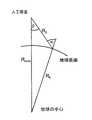
図6は、球形の地球の幾何学的配置における角度および半径の定義を図示し、
図7は、アレー走査角を、エコー時間の関数として表す図であり、
図8は、受信開口の可能な態様を示し、
図9は、連続多重配置されたホーンを経由する送信用の送信開口の可能な態様を示す。
【0018】
2.機器の構成
本発明のSAR機器の構成は、分離した送信開口を、縦およびアジマス方向の多数の受信開口と組み合わせる。以下、初めに縦方向の多数の副開口の原理を説明し、次にアジマス方向の多数の副開口の原理を説明する。その後、両原理を組み合わせる。
【0019】
本発明のSAR機器の構成は、送信および受信のための二つの分離された開口を有する。バイスタティックレーダーの二つの開口は、宇宙空間を飛ぶ同一のまたは二つの異なる人工衛星に取り付けることができる。これは、おのおののアンテナの電気的デザインならびに送信および受信のためのRFエレクトロニクスを最適化することを可能にする。開口の合計サイズは、送信および受信の間で交換および変更することもできる。
【0020】
送信開口の大きさにより、ひとつのレーダーパルスで照らされる標的領域が決定される。縦方向の送信開口の大きさは最終的な画像走査幅に反比例する。より広く画像化された走査幅を生み出すためには、縦方向の送信開口の大きさhtxは、従来のSARシステムにおける場合よりも、小さくしなければならない。アジマス寸法(azimuth dimension)は最大の受信可能なアジマス分解能に比例する。
【0021】
より小さい送信利得を補うために、縦方向の全受信開口の大きさは従来のシステムにおけるものよりも大きい。それは多くの副開口に分割されている。おのおのの副開口は、送信開口によって照らされる領域をカバーしなければならず、したがって、その縦方向サイズhrxは送信開口の縦方向サイズより小さいか同じでなければならない。副開口の縦方向サイズを制限する二つ目の要件は、副開口の信号を結合させるとき、結果として生じるアンテナパターンに生成した量子化ローブがあるレベルよりも低くなければならないことである。おのおのの受信副開口のアジマス方向サイズは、送信開口のものと同じである。従来のシステムにおけるものと同じ放射条件を得るためには、もし、機器の他のパラメーター全てが同じままであるならば、送信開口の大きさと受信開口の合計の大きさとの積が、従来の開口の大きさの二乗と同一であるべきである。(分離された送信および受信経路の最適化されたデザインによって、より低い損失およびより低い雑音指数を実現することができると期待されている。これはまた、SAR機器の効率を向上させ、より低い利得を部分的に補いうる。)
【0022】
おのおのの副開口からの信号は、分離されたチャンネルで受信される。おのおののチャンネルは、分離された入力を、続くデジタル信号処理に供給する。
【0023】
2.1.縦方向の多数の受信副開口
広い画像化走査幅およびアジマス方向での高い分解能は、すぐ前の段落で説明したように、従来のSARシステムのデザインに比べて、小さい送信開口を使うことを必要とする。
【0024】
送信開口の大きさのこの縮小は、従来のSARシステムに比べて、受信される信号の電力(レーダー方程式によって決定される)の減少を引き起こし、そのため、画像における放射分解能(radiometric resolution)が減少する。放射性能を改善するためには、送信電力および/または有効受信開口サイズを増加させることができる。提示された本概念では、この二つ目を、より大きな受信開口を縦方向に多数の受信副開口から形成することにより、実現することができる。
【0025】
独立におのおのの副開口から受信されたエコーは、時間および周波数依存性位相関数によって位相をずらされ、その後、コヒーレントに他の受信開口からの信号と、前処理において結合される。もし、この前処理を人工衛星上で実現できれば、結果として得られる受信データ転送速度は、ひとつの受信チャンネルを持つレーダーについてのものと同じである。
【0026】
事実上、多数の受信開口の信号の処理は、複数ビーム形成過程(multiple beam forming process)とみなすことができる。この過程において、結果として生じたビームは、図1に示したように、送信開口の縦方向の−3dB点の間で指向される。
【0027】
処理の間におけるビームの指向により、結果として生じるアンテナ受信パターンに量子化ローブが生成しうる。これは、受信副開口の縦方向の大きさhrsを選択するときに、考慮しなければならない。一般的には、受信量子化ローブのレベルに関して要求されることは、アクティブフェーズドアレーアンテナの場合におけるほど厳密でなくてもよい。なぜなら、量子化ローブは受信パターンに現れるのみで、独立な送信パターンが偽信号抑制(alias signal suppression)の大部分を提供できるからである。原理の説明のために物事を単純に保つため、重みをつけないアンテナ開口のみを以下では調べる。アンテナテーパー(antenna taper)を導入することでさらに自由に最適化ができるようになる。
【0028】
縦構成(elevation configuration)における多数の受信開口を記述するパラメーターを図2に示し、表1に記載した。
【0029】
前述したように、送信開口の縦寸法(elevation dimension)htxに対する受信副開口の縦寸法hrsは、特定のグレーティングローブの最も高いレベルにより制約される。
【0030】
レーダー方程式から、観察された標的点のひとつについての信号対ノイズ比は、送信利得と受信利得との積に比例することが知られている。これはまた、送信開口面積と受信開口面積との積に比例する。多数の受信開口の構成を標準のモノスタティック単一送信/受信開口の概念と比較できるように、有効アンテナ開口を計算することができる。
式2
【0031】
【数2】
【0032】
【数3】
他の機器パラメーターが変化しないときに同じSNRをある点標的について維持するのに必要なバイスタティック構成の全アンテナ開口(送信+受信)Abiは以下のように計算される。パラメーターA=l・hは、同じSNR(ただし、より小さな走査幅)を与えるモノスタティック構成における対応するアンテナ表面である。
式4
【0034】
【数4】
式2を挿入すると、次のものが得られる。
式5
【0036】
【数5】
この簡単化したモデルにおいて、地上距離(ground range)方向で画像化された走査幅が縦方向のアンテナビーム幅に比例すると仮定できる。これは、画像化されうる走査幅が縦方向の送信開口寸法htxに反比例することを意味する。
【0038】
式5から、どのようにして、送信開口の高さhtx、受信開口の高さhrx、および、このものからさらに、画像化された走査幅が、モノスタティックアンテナの高さhおよび対応する走査幅を基準としたとき、Nの関数として関連しているかが分かる。
式6
【0039】
【数6】
画像化される走査幅は、縦方向の送信開口寸法htxが減少すると、
【0041】
このことから、モノスタティックSARシステムと異なり、提案された本バイスタティックSARシステムの概念においては、画像化された走査幅は、放射分解能および幾何学的分解能を減少させることなく、受信開口の高さhrxに比例して増加するという結論が導かれる。
【0042】
2.2.レンジ方向のあいまいさによる走査幅の限界
レンジ方向の最大の達成可能な走査幅を制限するひとつの要因はレンジ方向のあいまいさである。レンジ方向のあいまいさは、アンテナが同時に、後続するパルスから生じるエコーであって、そのために区別することができないエコーを受信したときに生じる。これは、常に多数の後続するパルスが「空」中に同時に存在する人工衛星搭載の場合に起こりうる。これらのパルスの間の距離は、パルス繰返し周波数(PRF)を減少させることにより、増加させることができる。しかし、PRFには下限がある。なぜなら、アジマススペクトル(azimuth spectrum)は正確にサンプルされなければならないからである。ひとつのよい目安は、次のパルスが遅くとも、人工衛星がアンテナのアジマス長さ(azimuth length)lの1/2だけ前進したときに送られることである。このことにより、最小のPRFは式7において定義される。
式7
【0043】
【数7】
より悪い場合はあるPRFについて達成可能な走査幅wswが最小となる場合であるが、これは、式8において見ることができるように最大の入射角φiにおいて見出しうる。入射角φiは、地球表面上の局所的な法線ベクトルと、波が接近してくる方向との間の角度として定義される。さらに、パルス間の時間間隔の最大80%のみが、エコーを受信するために使用できると仮定する。残りの時間は、送信パルスおよびガードタイムのために確保する。光速をc0と表す。
式8
【0045】
【数8】
式8は、全走査幅にわたって一定の入射角を仮定しているので、近似である。
【0047】
2.3.アジマス方向の多数の受信副開口
高いアジマス分解能と広い走査幅との間のこの矛盾は、多数の(例えば、M個の)受信開口がアジマス方向に配置される構成により解決できる。この配置により、アジマススペクトルの正確なサンプリングが、アンテナアジマス寸法の合計に合うPRFを用いることで、可能になる。このPRFは、副開口の大きさlに必要なPRFよりもM倍小さい。これは、全てのパルスについてエコーがM個の異なる位置でサンプルされるので、可能である。実効的な位相中心は送信開口と受信開口との間の中央に位置しているので、アジマス方向のサンプリング間隔の最大値l/2は満たされる。この変位位相中心システムオペレーション(displaced phase center system operation)[2]を図3に示した。
・放射の要件を満たすために、おのおのの各受信開口は段落2.1で導出したような開口の大きさを持っていなければならない。
・おのおのの副開口で受信されるエコーは別々に保存されなければならない。
【0048】
縦方向の多数の副開口およびアジマス方向の多数の副開口という概念を組み合わせることができる。このような構成は図4に示されている。
【0049】
縦方向およびアジマス方向の多数の受信開口を持つ構成は、表2に示した5個のパラメーターのセットで特徴づけることができる。
【0050】
受信開口は、アジマス方向には寸法L=M・lを、縦方向にはhrx=N・hrsを持つ。
【0051】
2.4.関心のある領域の選択
関心のある領域への指向は人工衛星の回転により実現することができる。ストリップマップモードにおける走査幅は、従来のSARシステムを用いる場合よりも大きく、十分であるので、付加的なスキャンSARモードは広走査幅への応用のためには必要ない。機械的に指向するので、異なる距離の点において新たな走査幅を選択するのには、アクティブフェーズドアレーアンテナが装備されているSARシステムを用いる場合より多くの時間を必要とする。
【0052】
3.機上信号処理
提示された本概念では、おのおのがひとつの受信信号を提供する多数の受信副開口がなければならない。これにより、機上で保存され、その後、(N・M)個の受信副開口により地上に送信されなければならないデータ量が増加することになる。このことは、高分解能広走査幅レーダーシステム(high resolution wide swath radar system)にとっては特に重大である。このようなシステムでは、いかなる場合においても大容量のデータを扱うことが必要である。SARデータを画像へと処理する際には、異なる受信信号を結合させなければならない。データ量を減らすために、少なくともその処理のこの部分は機上で行うことを提案する。
【0053】
本概念は、縦方向およびアジマス方向の多数の受信副開口を前提とする。アジマス方向の多数の受信副開口は、要求されるPRFを減少させるために使われる。このため、アジマス方向の受信開口の多重化は実効データ転送速度を増加させず、データの減少は可能ではない。
【0054】
これは、ひとつの列の中に配置された縦方向の多数の受信副開口とは異なる。一つの列の内部にある異なる受信副開口からの信号を結合させて、全ての必要な情報を含んだひとつの信号にすることが可能である。原理的には、これは、各信号の時間変動性位相ずれと、それに続くエコー信号の合計とによって行われる。この位相ずれは、デジタル的に、例えば、時間変動性位相の乗算により実現することができる。レーダー信号が地球の表面上を伝わるときに、レーダーエコー信号が、前記合計された信号として最大化される方法で、時間変動性位相ずれは行われる。
【0055】
列内のN個の副開口からのN個の信号のこの合計のあとは、M個の列からのM個の信号だけが機上で保存され、その後、地上に送信されなければならない。これは、N倍のデータ減少に相当する。
【0056】
短パルスの代わりにチャープ信号を使うレーダーシステムについては、正確な時間変動性位相ずれが、周波数に伴って変動するが、これは、送信パルスのより長い継続時間と、線形な時間との関係が線形チャープにおける時間と周波数との間にはあることとによる。これは、時間変動性位相ずれに加えて、時間不変だが周波数には依存する位相ずれが必要であることを意味する。再び、適応性のあるこの時間・周波数変動性処理の目的は、結果として生じる信号においてレーダーエコー信号の電力を最大にすることである。周波数変動性位相ずれは、例えば、特別に設計された全通過フィルターを用いて、または周波数領域での変換後の位相乗算によって実現することができる。
【0057】
図5におけるブロック図は、信号処理操作および縦方向の異なる受信副開口からの信号の結合を示している。信号の処理は、各副開口からの信号のアナログ・デジタル変換に引き続いて、デジタル的に最もうまく行われるので、縦方向でのビーム形成ネットワーク(beam-forming network)は必要ない。
【0058】
上記の信号処理は、以下の工程を含むアルゴリズムによって実施できる:
【0059】
1.時間変動性位相ずれを、適合させた時間変動性位相の値をおのおのの副開口の信号に、時間変動性エコーの方向および受信開口のおける副開口の位置に応じて、乗算することにより、実行すること。
【0060】
2.この時間変動性位相ずれを、送信パルスにおける異なる時間について、おのおののエコー信号に適合させた周波数変動性位相ずれを導入することにより、修正すること。この周波数変動性位相ずれを、レーダーの形状および受信副開口の位置に適合させる。ひとつの実現方法は、全通過フィルターの伝達関数を適宜、設計することである。
【0061】
3.一列内の複数の副開口からの信号をコヒーレントに合計して、当該エコー信号について最大の処理利得を持つひとつの信号にすること。
【0062】
4.場合に応じて、結果として生じた信号を、BAQ様アルゴリズム(ブロック(Block)適応量子化のBAQ法[2])を用いて、圧縮することができる。
【0063】
5.生のデータからSAR画像を形成するために、この信号を用いて従来のSAR画像処理を行わなくてはならない。
【0064】
3.1.時間変動性位相ずれの導出
局所的地球半径REを持つ局所的に球形である地球を、図6に示したように、仮定する。他のパラメーターは、軌道半径ROrbit、アンテナのボアサイトにおける入射角φi、送信アンテナの−3dB幅θtx、中心周波数における波長λ、および縦方向の副開口の位相中心の距離であって、副開口の高さに対応する距離hである。
【0065】
まず、短パルスSARシステムの状況を調べる。受信信号のタイミングは走査幅中心エコー時間(swath center echo time)techoおよびデータウィンドウの長さ(data window length)tdataによって特徴づけられる。
【0066】
所与の入射角φiに対するオフナディア角βは次の式で与えられる。
式9
【0067】
【数9】
アンテナのボアサイトは、オフナディア角βの方向に向いている。画像化される走査幅の限界は、オフナディア角で表すと、送信アンテナの3dB幅θtxによって定義される。近距離側の走査幅の端(near range swath edge)についてのオフナディア角はβn=β−θtx/2であり、遠距離側の走査幅の端(far range swath edge)についてはβf=β+θtx/2である。
式10
【0069】
【数10】
スラントレンジRsはエコー時間に、光速の半分で割ることにより、変換できるt=2Rs/c0。これを組み合わせて、近距離時間(near range time)tnおよび遠距離時間(far range time)tfが次の式で定義される。
式11
【0071】
【数11】
サンプルしなければならないエコーウィンドウ(echo window)時間は簡単に差techo=tf−tnで与えられる。走査幅中心エコー時間はtcenter=(tf+tn)/2で与えられる。
【0073】
次の工程では、生じる受信パターンをアンテナのボアサイトから向け放たなければならない角度θをエコー時間の関数として決定しなければならない。このためには、式12を逆転しなければならない。
式12
【0074】
【数12】
この逆転は式13において与えられる。
式13
【0076】
【数13】
エコー時間の関数としての角度θを、図7において、一組の現実的なパラメーター:φi=45°、θtx=3.8°(0.1mの送信アンテナの高さに対応)、ROrbit=7038km、RE=6378kmを用いて、示した。ここで、エコー時間とアレー走査角との間の関係は一次関数に似ている。より広い走査幅およびより大きいθtxについては、非線形性が、地球の曲率によって、より目立つようになる。
【0078】
時間変動性走査角θ(t)の線形近似を見出すために、式13を時間について微分しδθ(t)/δt、式の値を走査幅中心時間(swath center time)tcにおいて求めた。
式14
【0079】
【数14】
【0080】
【数15】
図7において、式13由来の関数θ(t)およびその線形近似を示した。
【0082】
3.1.1.異なる受信副開口の走査角
次の工程では、受信開口の走査角は、サブアレーから到達する個々の信号における位相のずれに変換されなければならない。この解析は、電子走査アレーについてのものと同様に行われる。アナログでRF帯において位相のずれを実現する代わりに、それはデジタルでコンプレックス・イクイバレント・ベーシス・バンド(complex equivalent basis band)において実現される。
【0083】
位相中心の位置はサブアレーの中心に位置すると仮定される。dnは、n番目のサブアレー位相中心の、受信開口の中心からの有向距離であり、当該開口の中心よりも上に位置していれば正である。レーダー波長λとともに、おのおのの副開口の信号について実行される現実の位相のずれγnを指向角θの関数として式16で計算することができる。
式16
【0084】
【数16】
3.2.チャープSARシステムについての時間−周波数変動性位相ずれの導出
3.1章で与えられた時間変動性位相ずれは、周波数変調送信信号が短パルスの代わりに、要求されたレンジ分解能を得るために用いられるとき、周波数依存性位相ずれによって拡張されなければならない。
【0086】
線形チャープで動作するSARシステムは、既に与えられたパラメーターに加えて、パルス幅τp、SAR信号帯域幅B、チャープ率(chirp rate)κ=B/τp、およびA/D変換器のサンプリング周波数fsで記述される。チャープシステムでは、画像化された走査幅に由来するエコーはパルス幅によって拡大される。したがって、この場合、エコーウィンドウはtecho=tf−tn+τpにより与えられる。
【0087】
短パルスシステムでは、生じる受信ビームパターンを常に、エコーが発生する方向に向けることができる。長パルスの場合、これは、パルス中の一箇所について可能であるのみである。パルスの残りの部分は、アンテナの全受信利得を受信するわけではない。これは、付加的に周波数依存性ビームステアリング(beam steering)が加えられたとき、補償されうる。時間領域での位相乗算であって、パルスの中心をたどる位相乗算の後、スペクトル領域における二回目の位相乗算であって、適切なビームステアリングに対してパルス内の全ての部分について実行する位相乗算が行われる。これは、時間と周波数との間の直接的な関係が線形チャープ信号にはあることにより、可能である。
【0088】
以下の工程が、異なる副開口からのエコー信号をチャープ信号の場合に結合させるために必要である。
【0089】
1.時間信号に時間変動性位相関数γn(t)を全ての副開口について乗算して、開口の指向角θch(t)を実現すること。式13で示された短パルスシステムの指向角との違いは、この指向角が、チャープの中心周波数に対応するパルスの中央について計算されることである。したがって、式に示されたチャープシステムの指向角θch(t)は、θ(t)をτp/2だけ遅らせたものによって与えられる。
式17
【0090】
【数17】
2.周波数−B/2≦f≦B/2について走査角θf(f)を実現して、チャープの時間にわたる信号の広がりを補償すること。
式18
【0092】
【数18】
3.指向角θch(t)およびθf(f)を、おのおのの副開口の信号または信号のスペクトルの乗算のための位相の値に、式16を用いて、変換する。スペクトルを線形位相によって変調することは、おのおのの副開口に適合させた信号の時間遅れによって実現することができる。全サンプリング周期に対応する時間遅れの部分は、多数のクロックサイクルについてデータを保存することにより実現することができる。サンプリング周期の端数に対応する時間遅れの部分は、データの内挿により実現することができる。この内挿をデジタルで実現するひとつの方法は、内挿フィルターを用いることによるものである。サブサンプリング周期の遅れは、アナログ・デジタル変換器用のクロック信号を変動させることにより実現することもできる。
【0094】
4.可能な技術的実施
4.1.受信開口の技術
全受信開口は、比較的大きな構造になる可能性があるが、打ち上げ、およびその後の宇宙での配備のためには、格納されうるものでなければならない。この目的のためには、その構造は硬く、軽量で、かつできれば薄いことが重要である。低ノイズ増幅器よりも前において、全システム損失(total system losses)およびシステムの雑音指数を低く抑えるために、電気的に要求されることものは、高い帯域幅と低い電気的損失であり、製造コストは低くすべきである。
【0095】
マイクロストリップパッチラジエーターには、これらの要件を満たす非常に高い可能性がある。いくつかのパッチの裏側で、低ノイズ増幅器が中央RFエレクトロニクスへの信号送信を増幅する。受信経路の電力消費は比較的低いので、LNAの温度安定化が位相変動に出会うように検討することができる。副開口あたりのLNAの数は、要求される雑音指数を満たすためにLNAよりも前において許容できる損失により、およびひとつの副開口に要求される出力電力により、決定される。
【0096】
このラジエータであれば、必要な機械的支えを提供するハネカム炭素繊維サンドイッチの上に取り付けることができる(図8参照)。最初の見積もりでは、記載された構造はXバンドにおいて、約8kg/m2の重さがあり、厚さは30mm未満である。
【0097】
4.2.送信開口の技術
受信開口と比べると、送信開口は比較的小さい。主に強調すべき点は、生成するRFエネルギーをできるだけ低い損失で放射することである。RFエネルギーを生成するためには、進行波管(TWT)を、中電源モジュール(Medium Power Modules(MPM))と同様に用いることができる。
【0098】
システムの設計によっては、副開口は縦方向よりもアジマス方向にはるかに長い。これには、場合によっては多重の給電線を備えた特殊な反射体のデザインが必要である。別の方法を挙げるとすれば、直接、多数のホーンから放射することである。多数のMPMとともに、それらを連続多重化して、送信開口を形成することができる(図9参照)。これらのユニットの数は十分に多いので、冗長性の概念としてグレースフルデグラデーションを提供することができる。
【0099】
5.参考文献
【0100】
[1]J. C. Curlander and R. N. McDonough、Synthetic Aperture Radar Systems and Signal Processing、New York: Wiley、1991、21頁以降
【0101】
[2]A. Currie, M. A. Brown、Wide-swath SAR、IEE Proceedings-F、139巻、2号、1992年4月
【0102】
[3]R. Kwok, W. T. K. Johnson、Block Adaptive Quantization of Magellan SAR Data、1989、IEEE Trans. Geoscience & Remote Sensing、27巻、4号、375−383頁
【0103】
[4]P. Meisl, A. Thompson, A. Luscombe、RADARSAT-2 Mission: Overview and Develop-ment Status、Proceedings of EUSAR 2000[5]J. H. G. Ender、Detection and Estimation of Moving Target Signals by Multi-Channel SAR、AEUE Int. J. Electron Commun. 50(1996) 2号、150−156
【0104】
[5]Fuk K. Li, R. M. Goldstein、Studies of Multibaseline Spaceborne Interferometric Synthetic Aperture Radars、IEEE Transactions on Geoscience and Remote Sensing、28巻、1号、1990年1月
【0105】
6.表
【0106】
【表1】
表1:縦構成における多数の受信開口を記述するパラメーター
【0108】
【表2】
表2:縦方向およびアジマス方向の多数の副開口を持つ受信開口を特徴づけるパラメーター
【図面の簡単な説明】
【0110】
【図1】受信において多数の開口を組み合わせることの原理を図示する。
【図2】縦方向(in elevation)の多数の受信開口を示す。
【図3】アジマス方向の多数の受信開口を用いたときの実効的な位相中心の位置を示す。
【図4】アジマスおよび縦方向の多数の受信開口を示す。
【図5】縦方向の異なる受信開口からの信号の結合を示すブロック図である。
【図6】球形の地球の幾何学的配置における角度および半径の定義を図示する。
【図7】アレー走査角を、エコー時間の関数として表す図である。
【図8】受信開口の可能な態様を示す。
【図9】連続多重配置されたホーンを経由する送信用の送信開口の可能な態様を示す。【Technical field】
[0001]
The present invention relates to a lateral monitoring SAR (Synthetic Aperture Radar) system.
[Background]
[0002]
1. Limitations of conventional SAR systems
For conventional SAR systems, the detection range in the cross track direction and the geometric resolution in the along track direction are conflicting system parameters.
[0003]
In conventional monostatic SAR systems, the same real aperture of length L and height H is used for transmission and reception. [1] indicates that a minimum antenna aperture A is required to sample the required target area radar echoes without ambiguity.
[0004]
[Expression 1]
In
[0006]
In the case of an airborne SAR, this constraint is less important. Because the speed of the platform vS And slant range Rs This is because the number of digits is smaller than in the case of spaceborne. The minimum antenna size is a very important consideration in the case of satellite installations. Conventional SAR systems overcome these limitations using special modes of operation. They are called spotlight and scan SAR modes [2].
[0007]
Spotlight mode allows azimuth resolution to be improved by directing the antenna beam to a point instead of a longer aperture. The disadvantage is that this allows only a single high resolution point to be imaged, but not a continuous detection range.
[0008]
Scan SAR mode is used to quickly switch a highly fast antenna beam between a number of N subswaths. This results in improved scan width, but at the cost of azimuth resolution being reduced by N + 1 times.
[0009]
German Patent Application Publication No. 3430749 describes a method for expanding scan width and reducing data in a SAR system. This method takes advantage of the fact that there is a slight difference in Doppler history from different distance ranges to the target. Target echoes from different distance ranges are received on a single receive channel and transmitted to the ground as a single echo. There, echoes of different distance ranges can be separated by individual Doppler histories.
[0010]
The system described in [3] has a special mode for improved along track resolution. During reception, the aperture is divided into two sub-apertures in azimuth, and each sub-aperture signal is recorded separately and transmitted to the ground for SAR processing. Similar segmentation in the azimuth direction can be used to detect moving targets.
[0011]
The principle of detection of moving targets is described in detail in [4]. This requires multiple receive channels and multiple receive antennas or sub-apertures separated in the direction of trajectory. Special signal processing algorithms allow them to detect moving targets in the SAR image.
[0012]
Another technique that uses two receive apertures and a receive channel is SAR interferometry [5]. In this, the two receiving apertures must be separated in the longitudinal or trajectory orthogonal direction. The separation required for interferometry is on the order of tens or hundreds of meters. Here again, the two signals must be recorded separately and are only combined after SAR image processing.
DISCLOSURE OF THE INVENTION
[Problems to be solved by the invention]
[0013]
An object of the present invention is to overcome the above limitations of conventional SAR systems. The new SAR system can combine high azimuth resolution with improved scan width and continuous lossless detection range in strip map mode.
[Means for Solving the Problems]
[0014]
The SAR system according to the invention is a bistatic radar, the receiving antenna of which is formed from azimuth and a number of receiving sub-apertures in the longitudinal direction. Coherent data processing for reducing the amount of data is performed on the machine using a signal from the sub-aperture.
【The invention's effect】
[0015]
The present SAR system for satellite-borne applications can combine very high geometric resolution with a very wide detection range. Such a SAR system is suitable, for example, for wide-area monitoring and high-resolution mapping. In particular, the SAR system of the present invention allows a very high azimuth resolution to be combined with an improved scan width.
[0016]
Both the higher detection range in the trajectory orthogonal direction and the higher geometric resolution in the trajectory direction require an increase in average transmit power in conventional SAR systems. The SAR system of the present invention allows the required average transmit power to be reduced by using a receive antenna with higher antenna gain and an optimized design of separate transmit and receive antennas.
BEST MODE FOR CARRYING OUT THE INVENTION
[0017]
The present invention will now be described in more detail with reference to the accompanying drawings. Of which
FIG. 1 illustrates the principle of combining multiple apertures in reception,
FIG. 2 shows a number of reception apertures in the elevation direction,
FIG. 3 shows the position of the effective phase center when using a large number of receiving apertures in the azimuth direction.
FIG. 4 shows azimuth and multiple receive apertures in the longitudinal direction,
FIG. 5 is a block diagram showing the coupling of signals from different reception apertures in the vertical direction;
FIG. 6 illustrates the definition of angles and radii in the spherical earth geometry,
FIG. 7 is a diagram representing array scan angle as a function of echo time;
FIG. 8 shows a possible embodiment of the receive aperture,
FIG. 9 shows a possible embodiment of a transmission aperture for transmission via horns arranged in series.
[0018]
2. Equipment configuration
The SAR equipment configuration of the present invention combines separate transmit apertures with multiple receive apertures in the longitudinal and azimuth directions. Hereinafter, the principle of a large number of sub-openings in the vertical direction will be described first, and then the principle of a large number of sub-openings in the azimuth direction will be described. Then combine both principles.
[0019]
The configuration of the SAR device of the present invention has two separate apertures for transmission and reception. The two apertures of the bistatic radar can be attached to the same or two different satellites flying in outer space. This makes it possible to optimize the electrical design of each antenna and the RF electronics for transmission and reception. The total size of the aperture can also be exchanged and changed between transmission and reception.
[0020]
The target area illuminated by one radar pulse is determined by the size of the transmission aperture. The size of the vertical transmission aperture is inversely proportional to the final image scan width. To produce a wider imaged scan width, the vertical transmission aperture size htx Must be smaller than in a conventional SAR system. The azimuth dimension is proportional to the maximum receivable azimuth resolution.
[0021]
To compensate for the smaller transmission gain, the vertical total receive aperture size is larger than in conventional systems. It is divided into many sub-openings. Each sub-aperture must cover the area illuminated by the transmit aperture and thus its longitudinal size hrx Must be less than or equal to the vertical size of the transmit aperture. The second requirement to limit the vertical size of the sub-aperture is that when the sub-aperture signals are combined, the resulting quantization lobe in the resulting antenna pattern must be below a certain level. The size in the azimuth direction of each reception sub-aperture is the same as that of the transmission aperture. To obtain the same radiation conditions as in conventional systems, if all other parameters of the equipment remain the same, the product of the transmit aperture size and the total receive aperture size is the conventional aperture Should be the same as the square of the magnitude of. (It is expected that the optimized design of separate transmit and receive paths can achieve lower loss and lower noise figure. This also improves the efficiency of SAR equipment and lower Can partially compensate for the gain.)
[0022]
The signal from each sub-aperture is received on a separate channel. Each channel provides a separate input for subsequent digital signal processing.
[0023]
2.1. Multiple receiving sub-apertures in the vertical direction
The wide imaging scan width and high resolution in the azimuth direction necessitates the use of a small transmit aperture compared to conventional SAR system designs, as described in the immediately preceding paragraph.
[0024]
This reduction in the size of the transmit aperture causes a reduction in the power of the received signal (determined by the radar equation) compared to conventional SAR systems, thus reducing the radiometric resolution in the image. . In order to improve the radiation performance, the transmit power and / or the effective receive aperture size can be increased. In the present concept presented, this second can be realized by forming a larger receiving aperture from a number of receiving sub-apertures in the vertical direction.
[0025]
Independently received echoes from each sub-aperture are phase shifted by a time and frequency dependent phase function and then coherently combined with signals from other receive apertures in pre-processing. If this pre-processing can be realized on an artificial satellite, the resulting received data rate is the same as that for a radar with one receiving channel.
[0026]
In effect, the processing of multiple receive aperture signals can be viewed as a multiple beam forming process. In this process, the resulting beam is directed between the -3 dB points in the longitudinal direction of the transmit aperture, as shown in FIG.
[0027]
Beam pointing during processing can generate quantization lobes in the resulting antenna reception pattern. This is the vertical size h of the reception sub-aperture.rs Must be considered when choosing. In general, what is required with respect to the level of received quantization lobes may not be as strict as in the case of active phased array antennas. This is because the quantization lobe only appears in the received pattern, and an independent transmission pattern can provide most of the alias signal suppression. To keep things simple to explain the principle, only the unweighted antenna aperture is examined below. Introducing an antenna taper allows more freedom for optimization.
[0028]
Parameters describing a number of receive apertures in the elevation configuration are shown in FIG.
[0029]
As mentioned above, the vertical dimension (elevation dimension) of the transmission aperture htx Vertical dimension h of the receiving sub-opening with respect tors Is constrained by the highest level of a particular grating lobe.
[0030]
From the radar equation, it is known that the signal-to-noise ratio for one of the observed target points is proportional to the product of the transmission gain and the reception gain. This is also proportional to the product of the transmit aperture area and the receive aperture area. The effective antenna aperture can be calculated so that multiple receive aperture configurations can be compared to the standard monostatic single transmit / receive aperture concept.
[0031]
[Expression 2]
[0032]
[Equation 3]
Full antenna aperture (transmit + receive) A in a bistatic configuration necessary to maintain the same SNR for a point target when other instrument parameters do not changebi Is calculated as follows: The parameter A = l · h is the corresponding antenna surface in a monostatic configuration that gives the same SNR (but smaller scan width).
Formula 4
[0034]
[Expression 4]
Inserting
Formula 5
[0036]
[Equation 5]
In this simplified model, it can be assumed that the scan width imaged in the direction of the ground range is proportional to the antenna beam width in the vertical direction. This is because the transmission width h in which the scan width that can be imaged is verticaltx Means inversely proportional to
[0038]
From equation 5, how is the height h of the transmission aperture?tx , Height of receiving aperture hrx And from this it can further be seen that the imaged scan width is related as a function of N, relative to the monostatic antenna height h and the corresponding scan width.
Equation 6
[0039]
[Formula 6]
The scanning width to be imaged is the transmission aperture dimension h in the vertical directiontx Decreases
[0041]
Thus, unlike the monostatic SAR system, in the proposed concept of the present bistatic SAR system, the imaged scan width does not reduce the radial and geometric resolution, but the height of the receive aperture. hrx The conclusion is drawn that it increases in proportion to
[0042]
2.2. Scan width limit due to ambiguity in range direction
One factor that limits the maximum achievable scan width in the range direction is the ambiguity in the range direction. Range ambiguity arises when the antenna simultaneously receives an echo that originates from a subsequent pulse and therefore cannot be distinguished. This can happen in the case of an onboard satellite where there are always many subsequent pulses simultaneously in the “sky”. The distance between these pulses can be increased by decreasing the pulse repetition frequency (PRF). However, PRF has a lower limit. This is because the azimuth spectrum must be accurately sampled. One good indication is that the next pulse will be sent at the latest when the satellite has advanced by 1/2 of the antenna's azimuth length l. This defines the minimum PRF in Equation 7.
Equation 7
[0043]
[Expression 7]
Scanning width w achievable for a PRF if worsesw Is the smallest, this is the maximum incident angle φ as can be seen in Equation 8.i Can be found in Incident angle φi Is defined as the angle between the local normal vector on the Earth's surface and the direction in which the wave approaches. Further assume that only up to 80% of the time interval between pulses can be used to receive echoes. The remaining time is reserved for transmission pulses and guard time. Light speed c0 It expresses.
Equation 8
[0045]
[Equation 8]
Equation 8 is approximate because it assumes a constant angle of incidence over the entire scan width.
[0047]
2.3. Multiple receiving sub-apertures in azimuth direction
This discrepancy between high azimuth resolution and wide scan width can be solved by a configuration in which a large number (eg, M) of receive apertures are arranged in the azimuth direction. This arrangement allows accurate sampling of the azimuth spectrum using a PRF that matches the total antenna azimuth dimensions. This PRF is M times smaller than the PRF required for the size l of the sub-opening. This is possible because the echo is sampled at M different positions for every pulse. Since the effective phase center is located at the center between the transmission aperture and the reception aperture, the maximum value l / 2 of the sampling interval in the azimuth direction is satisfied. This displaced phase center system operation [2] is shown in FIG.
• Each receive aperture must have an aperture size as derived in paragraph 2.1 to meet the radiation requirements.
• Echoes received at each sub-aperture must be stored separately.
[0048]
The concepts of multiple sub-openings in the vertical direction and multiple sub-openings in the azimuth direction can be combined. Such an arrangement is shown in FIG.
[0049]
A configuration with multiple receive apertures in the longitudinal and azimuth directions can be characterized by the set of five parameters shown in Table 2.
[0050]
The receiving aperture has a dimension L = M · l in the azimuth direction and h in the vertical direction.rx = Nhrs have.
[0051]
2.4. Select area of interest
Direction to the area of interest can be achieved by rotation of the satellite. Since the scan width in strip map mode is larger and sufficient than when using a conventional SAR system, an additional scan SAR mode is not required for wide scan width applications. Because it is mechanically oriented, selecting a new scan width at different distance points requires more time than using a SAR system equipped with an active phased array antenna.
[0052]
3. On-board signal processing
In the present concept presented, there must be a large number of receive sub-apertures, each providing a single received signal. This increases the amount of data that must be stored on board and then transmitted to the ground by (N · M) receive sub-apertures. This is especially critical for high resolution wide swath radar systems. In such a system, it is necessary to handle a large amount of data in any case. When processing SAR data into an image, different received signals must be combined. In order to reduce the amount of data, it is suggested that at least this part of the processing be done on board.
[0053]
This concept assumes a large number of receiving sub-apertures in the vertical and azimuth directions. Multiple receive sub-apertures in the azimuth direction are used to reduce the required PRF. For this reason, multiplexing of reception apertures in the azimuth direction does not increase the effective data transfer rate, and data reduction is not possible.
[0054]
This is different from a large number of longitudinal receiving sub-apertures arranged in one row. It is possible to combine signals from different receive sub-apertures within a single row into a single signal containing all the necessary information. In principle, this is done by the time-varying phase shift of each signal followed by the sum of the echo signals. This phase shift can be realized digitally, for example, by multiplication of a time-varying phase. The time-varying phase shift is performed in such a way that when the radar signal travels on the surface of the earth, the radar echo signal is maximized as the summed signal.
[0055]
After this sum of N signals from N sub-apertures in a row, only M signals from M rows must be stored on board and then transmitted to the ground. This corresponds to a data reduction of N times.
[0056]
For radar systems that use chirp signals instead of short pulses, the exact time-varying phase shift varies with frequency, which is related to the longer duration of the transmitted pulse and the linear time. Because there is between time and frequency in a linear chirp. This means that in addition to the time-varying phase shift, a time-invariant but frequency-dependent phase shift is required. Again, the purpose of this adaptive time and frequency variability process is to maximize the power of the radar echo signal in the resulting signal. The frequency-variable phase shift can be realized, for example, using a specially designed all-pass filter or by phase multiplication after conversion in the frequency domain.
[0057]
The block diagram in FIG. 5 shows the signal processing operation and the combination of signals from different reception sub-apertures in the vertical direction. Since the signal processing is best done digitally following the analog-to-digital conversion of the signal from each sub-aperture, a beam-forming network in the longitudinal direction is not necessary.
[0058]
The above signal processing can be performed by an algorithm including the following steps:
[0059]
1. Perform time-varying phase shifts by multiplying each sub-aperture signal by the adapted time-varying phase value, depending on the direction of the time-varying echo and the position of the sub-aperture at the receive aperture. To do.
[0060]
2. Correct this time-varying phase shift by introducing a frequency-varying phase shift adapted to each echo signal for different times in the transmitted pulse. This frequency-varying phase shift is adapted to the radar shape and the position of the receiving sub-aperture. One implementation is to design the transfer function of the all-pass filter accordingly.
[0061]
3. The signals from a plurality of sub-apertures in a row are coherently summed into one signal having the maximum processing gain for the echo signal.
[0062]
4). In some cases, the resulting signal can be compressed using a BAQ-like algorithm (Block adaptive quantization BAQ method [2]).
[0063]
5. In order to form a SAR image from raw data, conventional SAR image processing must be performed using this signal.
[0064]
3.1. Derivation of time-varying phase shift
Local earth radius RE Assume a locally spherical earth with, as shown in FIG. The other parameter is the orbit radius ROrbit , Incident angle φ at the boresight of the antennai , −3 dB width θ of the transmitting antennatx , The wavelength λ at the center frequency, and the distance between the phase centers of the vertical sub-apertures, and the distance h corresponding to the height of the sub-apertures.
[0065]
First, the status of the short pulse SAR system is examined. The timing of the received signal is the scan width center echo time techo And data window length tdata Characterized by.
[0066]
Given incident angle φi The off-nadir angle β for is given by
Equation 9
[0067]
[Equation 9]
The boresight of the antenna is oriented in the direction of off-nadir angle β. The limit of the scan width that can be imaged is expressed in terms of off-nadir angle, 3 dB width θtx Defined by The off-nadir angle for the near range swath edge is βn = Β-θtx / 2 and β for the far range swath edgef = Β + θtx / 2.
Equation 10
[0069]
[Expression 10]
Slant range Rs Can be converted by dividing the echo time by half the speed of light t = 2Rs / C0 . Combining this, the near range time tn And far range time tf Is defined by the following equation.
Equation 11
[0071]
## EQU11 ##
The echo window time that must be sampled is simply the difference techo = Tf -Tn Given in. Scan width center echo time is tcenter = (Tf + Tn ) / 2.
[0073]
In the next step, the angle θ at which the resulting received pattern must be directed away from the antenna boresight must be determined as a function of echo time. For this, equation 12 must be reversed.
Formula 12
[0074]
[Expression 12]
This reversal is given in Equation 13.
Equation 13
[0076]
[Formula 13]
The angle θ as a function of echo time is shown in FIG. 7 as a set of realistic parameters: φi = 45 °, θtx = 3.8 ° (corresponding to a height of 0.1 m transmitting antenna), ROrbit = 7038 km, RE = 6378 km. Here, the relationship between echo time and array scan angle is similar to a linear function. Wider scan width and larger θtx For, the non-linearity becomes more noticeable with the curvature of the earth.
[0078]
In order to find a linear approximation of the time-varying scan angle θ (t), Equation 13 is differentiated with respect to time, δθ (t) / δt, and the value of the equation is the scan width center time tc Sought in.
Equation 14
[0079]
[Expression 14]
[0080]
[Expression 15]
FIG. 7 shows the function θ (t) derived from Equation 13 and its linear approximation.
[0082]
3.1.1. Scan angle of different reception sub-apertures
In the next step, the scan angle of the receive aperture must be converted to a phase shift in the individual signals arriving from the subarray. This analysis is performed in the same manner as for the electronic scanning array. Instead of realizing the analog phase shift in the RF band, it is realized digitally in a complex equivalent basis band.
[0083]
The position of the phase center is assumed to be at the center of the subarray. dn Is the directional distance from the center of the reception aperture of the n-th subarray phase center, and is positive if it is located above the center of the aperture. Real phase shift γ performed on each sub-aperture signal with radar wavelength λn As a function of the directivity angle θ.
Equation 16
[0084]
[Expression 16]
3.2. Derivation of time-frequency variability phase shift for chirp SAR systems
The time-varying phase shift given in Section 3.1 must be extended by a frequency dependent phase shift when the frequency modulated transmission signal is used to obtain the required range resolution instead of a short pulse. .
[0086]
A SAR system operating with a linear chirp has a pulse width τ in addition to the parameters already given.p , SAR signal bandwidth B, chirp rate κ = B / τp And the sampling frequency f of the A / D converters It is described by. In a chirp system, echoes derived from the imaged scan width are magnified by the pulse width. Therefore, in this case, the echo window is techo = Tf -Tn + Τp Given by.
[0087]
In short pulse systems, the resulting received beam pattern can always be directed in the direction in which the echo is generated. In the case of long pulses, this is only possible for one location in the pulse. The remaining part of the pulse does not receive the full receive gain of the antenna. This can be compensated for when additional frequency dependent beam steering is added. Phase multiplication in the time domain, followed by a phase multiplication that follows the center of the pulse, followed by a second phase multiplication in the spectral domain that is performed on all parts of the pulse for proper beam steering Is done. This is possible because the linear chirp signal has a direct relationship between time and frequency.
[0088]
The following steps are necessary to combine echo signals from different sub-apertures in the case of a chirp signal.
[0089]
1. Time-varying phase function γ for time signaln Multiply (t) for all sub-apertures to obtain the directivity angle θ of the aperturesch Realize (t). The difference from the directivity angle of the short pulse system shown in Equation 13 is that this directivity angle is calculated for the center of the pulse corresponding to the chirp center frequency. Therefore, the directivity angle θ of the chirp system shown in the equationch (T) represents θ (t) as τp Given by being delayed by / 2.
Equation 17
[0090]
[Expression 17]
2. Scanning angle θ for frequency −B / 2 ≦ f ≦ B / 2f Implement (f) to compensate for the spread of the signal over the chirp time.
Equation 18
[0092]
[Formula 18]
3. Directional angle θch (T) and θf (F) is transformed into the value of the phase for each sub-aperture signal or signal spectrum multiplication using Equation 16. Modulating the spectrum with a linear phase can be realized by a time delay of the signal adapted to each sub-aperture. The time delay portion corresponding to the entire sampling period can be realized by storing data for a number of clock cycles. The portion of the time delay corresponding to the fraction of the sampling period can be realized by data interpolation. One way to digitally implement this interpolation is by using an interpolation filter. The delay of the sub-sampling period can also be realized by changing the clock signal for the analog / digital converter.
[0094]
4). Possible technical implementation
4.1. Reception aperture technology
The total receive aperture can be a relatively large structure but must be able to be stored for launch and subsequent space deployment. For this purpose it is important that the structure is hard, light and preferably thin. Before the low noise amplifier, what is required electrically to keep the total system losses and the system noise figure low is high bandwidth and low electrical loss, which is the manufacturing cost Should be low.
[0095]
Microstrip patch radiators are very likely to meet these requirements. Behind some patches, a low noise amplifier amplifies signal transmission to the central RF electronics. Since the power consumption of the reception path is relatively low, it can be considered that the temperature stabilization of the LNA encounters phase variations. The number of LNAs per sub-aperture is determined by the loss that can be tolerated before the LNA to meet the required noise figure and by the output power required for one sub-aperture.
[0096]
This radiator can be mounted on a honeycomb carbon fiber sandwich that provides the necessary mechanical support (see FIG. 8). In the first estimate, the structure described is about 8 kg / m in the X band.2 The thickness is less than 30 mm.
[0097]
4.2. Transmission aperture technology
Compared to the reception aperture, the transmission aperture is relatively small. The main point to be emphasized is to radiate the generated RF energy with as low a loss as possible. In order to generate RF energy, traveling wave tubes (TWT) can be used as well as medium power modules (MPM).
[0098]
Depending on the design of the system, the sub-aperture is much longer in the azimuth direction than in the longitudinal direction. This may require special reflector designs with multiple feed lines in some cases. Another way is to radiate directly from multiple horns. With multiple MPMs, they can be continuously multiplexed to form a transmit aperture (see FIG. 9). The number of these units is large enough to provide graceful degradation as a concept of redundancy.
[0099]
5. References
[0100]
[1] JC Curlander and RN McDonough, Synthetic Aperture Radar Systems and Signal Processing, New York: Wiley, 1991, p. 21 et seq.
[0101]
[2] A. Currie, MA Brown, Wide-swath SAR, IEE Proceedings-F, Vol. 139, No. 2, April 1992
[0102]
[3] R. Kwok, WTK Johnson, Block Adaptive Quantization of Magellan SAR Data, 1989, IEEE Trans. Geoscience & Remote Sensing, 27, 4, 375-383
[0103]
[4] P. Meisl, A. Thompson, A. Luscombe, RADARSAT-2 Mission: Overview and Develop-ment Status, Proceedings of EUSAR 2000 [5] JHG Ender, Detection and Estimation of Moving Target Signals by Multi-Channel SAR, AEUE Int. J. Electron Commun. 50 (1996) No. 2, 150-156
[0104]
[5] Fuk K. Li, RM Goldstein, Studies of Multibaseline Spaceborne Interferometric Synthetic Aperture Radars, IEEE Transactions on Geoscience and Remote Sensing, Vol. 28, No. 1, January 1990
[0105]
6). table
[0106]
[Table 1]
Table 1: Parameters describing multiple receive apertures in a vertical configuration
[0108]
[Table 2]
Table 2: Parameters characterizing a receive aperture with multiple sub apertures in the longitudinal and azimuth directions
[Brief description of the drawings]
[0110]
FIG. 1 illustrates the principle of combining multiple apertures in reception.
FIG. 2 shows a number of receive apertures in the elevation direction.
FIG. 3 shows the position of an effective phase center when a large number of reception apertures in the azimuth direction are used.
FIG. 4 shows multiple receive apertures in azimuth and longitudinal direction.
FIG. 5 is a block diagram showing the combination of signals from different reception apertures in the vertical direction.
FIG. 6 illustrates the definition of angles and radii in a spherical earth geometry.
FIG. 7 is a diagram representing array scan angle as a function of echo time.
FIG. 8 shows a possible embodiment of the reception aperture.
FIG. 9 shows a possible embodiment of a transmission aperture for transmission via horns arranged in series.
Claims (7)
Translated fromJapanese- 前記送信開口とは異なる大きさを持ち、前記送信開口から分離された受信開口であって、縦およびアジマス方向に沿って配置された多数の受信副開口(sub-apertures)に分割された受信開口、
- おのおのの受信副開口の信号をコヒーレントに処理する手段であって、
・時間および/または周波数変動性位相の値によって、おのおのの受信副開口からの信号の位相をずらす手段、
・縦方向に沿って配列された受信副開口から生じる信号を合計する手段
を含み、
・レーダー送信信号が地球の表面上を伝わるときに、レーダーエコー信号が、前記合計された信号として最大化されるような方法で、前記時間および/または周波数変動性位相の値が生成される手段
を含む側方監視SARシステム。-Transmit aperture,
-A reception aperture having a different size than the transmission aperture and separated from the transmission aperture, divided into a number of reception sub-apertures arranged along the longitudinal and azimuth directions Opening,
-Means for coherently processing each received sub-aperture signal,
Means for shifting the phase of the signal from each receiving sub-aperture by the value of the time and / or frequency variability phase;
Comprising means for summing the signals arising from the receiving sub-apertures arranged along the longitudinal direction;
Means for generating the time and / or frequency variability phase values in such a way that when a radar transmission signal travels on the surface of the earth, a radar echo signal is maximized as the summed signal; Side-monitoring SAR system including
- 時間変動性位相の値をおのおのの受信副開口の信号に乗算する手段、
- チャープ送信信号を用いたSARレーダーの場合に、時間、周波数および方向の間での変動依存性を考慮に入れるために、周波数変動性位相の値を得られた信号に与える手段
を含むことを特徴とする側方監視SARシステム。The side-monitoring SAR system according to any one of the preceding claims, wherein the means for shifting the phase of the signal from each receiving sub-aperture when using a chirp SAR radar transmission signal,
-Means for multiplying each received sub-aperture signal by the value of the time-varying phase;
-In the case of a SAR radar using a chirp transmission signal, including means for giving the value of the frequency variability phase to the obtained signal in order to take into account the variation dependence between time, frequency and direction Features a side-monitoring SAR system.
- アナログ・デジタル変換器のクロック信号を制御してずらす手段、
- 信号サンプルを多数の全サンプリング周期によって遅らせる手段
を含むことを特徴とする側方監視SARシステム。5. The side monitoring SAR system of claim 4, wherein said means for providing a time delay is
-Means to control and shift the clock signal of the analog / digital converter,
A lateral monitoring SAR system comprising means for delaying the signal samples by a number of total sampling periods;
Applications Claiming Priority (2)
| Application Number | Priority Date | Filing Date | Title |
|---|---|---|---|
| EP01106289AEP1241487B1 (en) | 2001-03-15 | 2001-03-15 | Side-looking synthetic aperture radar system |
| PCT/EP2002/001269WO2002075353A1 (en) | 2001-03-15 | 2002-02-07 | Side-looking sar system |
Publications (3)
| Publication Number | Publication Date |
|---|---|
| JP2004523760Atrue JP2004523760A (en) | 2004-08-05 |
| JP2004523760A5 JP2004523760A5 (en) | 2008-05-22 |
| JP4191490B2 JP4191490B2 (en) | 2008-12-03 |
Family
ID=8176778
Family Applications (1)
| Application Number | Title | Priority Date | Filing Date |
|---|---|---|---|
| JP2002573908AExpired - LifetimeJP4191490B2 (en) | 2001-03-15 | 2002-02-07 | Side monitoring SAR system |
Country Status (8)
| Country | Link |
|---|---|
| US (1) | US6870500B2 (en) |
| EP (1) | EP1241487B1 (en) |
| JP (1) | JP4191490B2 (en) |
| AT (1) | ATE317549T1 (en) |
| CA (1) | CA2440796C (en) |
| DE (1) | DE60117065T2 (en) |
| ES (1) | ES2256102T3 (en) |
| WO (1) | WO2002075353A1 (en) |
Cited By (8)
| Publication number | Priority date | Publication date | Assignee | Title |
|---|---|---|---|---|
| JP2008203228A (en)* | 2007-02-23 | 2008-09-04 | Nec Corp | Synthetic aperture radar and the synthetic aperture radar image reproduction processing method |
| JP2009505037A (en)* | 2005-06-01 | 2009-02-05 | ネイダーランゼ、オルガニザティー、ボー、トゥーゲパストナトゥールウェテンシャッペルーク、オンダーツォーク、ティーエヌオー | Aircraft radar system |
| JP2009520954A (en)* | 2005-12-23 | 2009-05-28 | アストリウム・ゲゼルシャフト・ミット・ベシュレンクテル・ハフツング | High resolution synthetic aperture radar device and antenna for high resolution synthetic aperture radar device |
| JP2010085167A (en)* | 2008-09-30 | 2010-04-15 | Mitsubishi Electric Corp | Image radar system |
| JP2012524896A (en)* | 2009-04-21 | 2012-10-18 | アストリウム・リミテッド | Radar system |
| JP6687297B1 (en)* | 2018-12-28 | 2020-04-22 | 三菱電機株式会社 | Radar signal processing device and radar signal processing method |
| JP2022010005A (en)* | 2016-12-08 | 2022-01-14 | ユニバーシティ オブ ワシントン | Millimeter wave and/or microwave imaging systems and methods including examples of partitioned inverse and enhanced resolution modes and imaging devices |
| US11921193B2 (en) | 2016-08-12 | 2024-03-05 | University Of Washington | Millimeter wave imaging systems and methods using direct conversion receivers and/or modulation techniques |
Families Citing this family (49)
| Publication number | Priority date | Publication date | Assignee | Title |
|---|---|---|---|---|
| US6888490B1 (en)* | 2004-07-20 | 2005-05-03 | Raytheon Company | Spatial multibeam ambiguity resolving technique (SMART) |
| EP1949133B1 (en)* | 2005-11-16 | 2012-07-04 | Astrium Limited | Synthetic aperture radar |
| CN101059563B (en)* | 2006-04-20 | 2010-10-13 | 中国科学院电子学研究所 | Synthetic aperture radar impulse phase shift method |
| DE102006022814A1 (en) | 2006-05-13 | 2007-11-15 | Deutsches Zentrum für Luft- und Raumfahrt e.V. | High-resolution Synthetic Aperture Side View Radar System using Digital Beamforming |
| DE102007041373B3 (en) | 2007-08-30 | 2009-01-15 | Deutsches Zentrum für Luft- und Raumfahrt e.V. | Synthetic aperture radar method |
| DE102007060769A1 (en)* | 2007-12-17 | 2009-06-18 | Robert Bosch Gmbh | Monostatic multi-beam radar sensor, as well as methods |
| DE102008026497A1 (en)* | 2008-06-03 | 2010-01-07 | Astrium Gmbh | A method of optimizing the operation of an active side view sensor of variable height over the surface to be detected |
| US9857475B2 (en) | 2008-09-09 | 2018-01-02 | Geooptics, Inc. | Cellular interferometer for continuous earth remote observation (CICERO) |
| FR2938925B1 (en)* | 2008-11-21 | 2015-09-04 | Thales Sa | RADAR DEVICE FOR MARITIME SURVEILLANCE |
| ATE534043T1 (en)* | 2008-12-02 | 2011-12-15 | Thales Nederland Bv | MONITORING SYSTEM WITH A RADAR ANTENNA MOUNTED ON THE WING OF A WINDMILL |
| PL2394184T3 (en)* | 2009-02-06 | 2018-02-28 | Saab Ab | Radar system and method for a synthetic aperture radar |
| RU2009111512A (en)* | 2009-03-31 | 2010-10-10 | Открытое акционерное общество "Межгосударственная акционерная корпорация "Вымпел" (RU) | METHOD FOR REMOTE SENSING USING THE MULTI-POSITION RADAR SYSTEM AND A DEVICE FOR ITS IMPLEMENTATION |
| US8378879B2 (en)* | 2009-06-18 | 2013-02-19 | The Johns Hopkins University | Apparatus and methods for remote detection of physiological changes |
| WO2012000074A1 (en) | 2010-06-28 | 2012-01-05 | Institut National D'optique | Method and apparatus for compensating for a parameter change in a synthetic aperture imaging system |
| CA2802789C (en)* | 2010-06-28 | 2016-03-29 | Institut National D'optique | Synthetic aperture imaging interferometer |
| CN102270341B (en)* | 2011-04-20 | 2015-01-07 | 电子科技大学 | Adaptive high-precision phase estimation method for interferometric SAR (synthetic aperture radar) |
| DE102011107403B4 (en) | 2011-07-07 | 2013-01-17 | Astrium Gmbh | Radar system with synthetic aperture |
| US9531081B2 (en) | 2011-07-20 | 2016-12-27 | Deutsches Zentrum für Luft- und Raumfahrt e.V. | Reflector antenna for a synthetic aperture radar |
| FR2986334B1 (en)* | 2012-01-26 | 2014-02-21 | Centre Nat Etd Spatiales | SATELLITE RADAR INSTRUMENT FOR MARITIME SURVEILLANCE |
| DE102012219229A1 (en) | 2012-10-22 | 2014-04-24 | Deutsches Zentrum für Luft- und Raumfahrt e.V. | Interferometric SAR system |
| DE102012021010B4 (en) | 2012-10-26 | 2022-02-03 | Airbus Defence and Space GmbH | Synthetic aperture radar for simultaneous image acquisition and moving target detection |
| CN103823206B (en)* | 2014-03-11 | 2016-03-02 | 北京理工大学 | A kind of ground of the star based on Navsat double-base SAR time-frequency synchronization method |
| CN104020449B (en)* | 2014-05-15 | 2016-08-24 | 中国科学院电子学研究所 | A kind of interfering synthetic aperture radar phase diagram filtering method and equipment |
| US9588223B2 (en) | 2014-09-09 | 2017-03-07 | Raytheon Company | Phase center alignment for fixed repetition rate synthetic aperture systems |
| WO2016153914A1 (en) | 2015-03-25 | 2016-09-29 | King Abdulaziz City Of Science And Technology | Apparatus and methods for synthetic aperture radar with digital beamforming |
| WO2017044168A2 (en) | 2015-06-16 | 2017-03-16 | King Abdulaziz City Of Science And Technology | Efficient planar phased array antenna assembly |
| CA3044806A1 (en) | 2015-11-25 | 2017-06-01 | Urthecast Corp. | Synthetic aperture radar imaging apparatus and methods |
| US11378682B2 (en) | 2017-05-23 | 2022-07-05 | Spacealpha Insights Corp. | Synthetic aperture radar imaging apparatus and methods for moving targets |
| CA3064580A1 (en)* | 2017-05-23 | 2018-11-29 | King Abdullah City Of Science And Technology | Apparatus and methods for a synthetic aperture radar with multi-aperture antenna |
| CA3064735C (en) | 2017-05-23 | 2022-06-21 | Urthecast Corp. | Synthetic aperture radar imaging apparatus and methods |
| DE102017211294A1 (en)* | 2017-07-03 | 2019-01-03 | Deutsches Zentrum für Luft- und Raumfahrt e.V. | Synthetic aperture radar method and synthetic aperture radar system |
| EP3432027B1 (en)* | 2017-07-20 | 2021-09-01 | Airbus Defence and Space GmbH | High resolution wide swath synthetic aperture radar system |
| CA3083033A1 (en) | 2017-11-22 | 2019-11-28 | Urthecast Corp. | Synthetic aperture radar apparatus and methods |
| EP3521852B1 (en)* | 2018-01-31 | 2021-07-14 | Sivers Wireless AB | Radar beamforming method |
| CN109490847B (en)* | 2018-11-21 | 2020-01-31 | 中国科学院电子学研究所 | A Radar Signal Fast Recovery Method for Multi-pulse Combination Detection |
| CN109490883B (en)* | 2018-11-21 | 2020-06-09 | 中国科学院电子学研究所 | SAR (synthetic aperture radar) wide-range imaging method based on multi-pulse combination |
| CN109490884B (en)* | 2018-11-21 | 2020-08-07 | 中国科学院电子学研究所 | A Multi-pulse Combination Imaging Method for Anti-jamming SAR |
| CN109490885B (en)* | 2018-11-21 | 2020-01-21 | 中国科学院电子学研究所 | SAR deblurring imaging method based on multi-pulse combination |
| CN109286414B (en)* | 2018-11-22 | 2020-02-21 | 维沃移动通信有限公司 | A kind of antenna determination method and terminal |
| RU2703522C1 (en)* | 2018-12-21 | 2019-10-18 | Федеральное государственное бюджетное учреждение науки институт океанологии им. П.П. Ширшова Российской академии наук | Method of identifying an underwater hydrodynamic source from a high-speed sea surface radar image |
| US11262446B2 (en)* | 2019-02-22 | 2022-03-01 | Eagle Technology, Llc | Multi-channel split-swath (MCSS) synthetic aperture radar (SAR) |
| IT201900005444A1 (en)* | 2019-04-09 | 2020-10-09 | Thales Alenia Space Italia Spa Con Unico Socio | INNOVATIVE METHOD TO PERFORM SAR ACQUISITIONS WITH INCREASED SWATH DIMENSIONS |
| US11360209B2 (en) | 2019-05-03 | 2022-06-14 | Eagle Technology, Llc | Multiple beam antenna for wide swath satellite based SAR |
| WO2021086456A2 (en)* | 2019-07-05 | 2021-05-06 | Urthecast Corp | Systems and methods for determining operational parameters of a synthetic aperture radar |
| CA3089990A1 (en)* | 2019-08-20 | 2021-02-20 | Institut National D'optique | Method and system for detection and synthetic aperture imaging of a target |
| CN110966954A (en)* | 2019-10-31 | 2020-04-07 | 中国科学院长春光学精密机械与物理研究所 | Large aperture optical element surface shape splicing detection method and equipment |
| KR102260877B1 (en)* | 2021-02-22 | 2021-06-07 | 아주대학교산학협력단 | Method and Apparatus for Source Data Processing of Synthetic Aperture Radar Satellite |
| CN114089291B (en)* | 2022-01-19 | 2025-08-08 | 北京宏锐星通科技有限公司 | Device for jamming synthetic aperture radar |
| CN115184936B (en)* | 2022-09-13 | 2022-12-06 | 中国人民解放军国防科技大学 | Target full-angle sample generation method and device based on circular synthetic aperture radar |
Family Cites Families (9)
| Publication number | Priority date | Publication date | Assignee | Title |
|---|---|---|---|---|
| US4088978A (en)* | 1976-09-27 | 1978-05-09 | Westinghouse Electric Corp. | Synthetic aperture side-looking sonar system |
| GB2032723B (en)* | 1978-10-26 | 1988-09-07 | Marconi Co Ltd | Improvements in or relating to radar systems |
| US4325065A (en)* | 1979-08-09 | 1982-04-13 | Eaton Corporation | Bistatic imaging radar processing for independent transmitter and receiver flightpaths |
| FR2483086A1 (en)* | 1980-05-22 | 1981-11-27 | Martin Philippe | SIGNAL PROCESSING METHOD FOR SIDE-OPEN AND OPEN SYNTHESIZED RADAR AND IMPLEMENTATION CIRCUIT |
| US4727373A (en)* | 1986-03-31 | 1988-02-23 | Loral Corporation | Method and system for orbiting stereo imaging radar |
| JPH02210285A (en)* | 1989-02-10 | 1990-08-21 | Mitsubishi Electric Corp | Spot light maping radar device |
| JPH0727021B2 (en)* | 1989-02-10 | 1995-03-29 | 三菱電機株式会社 | Synthetic aperture radar device |
| US5295118A (en)* | 1993-02-18 | 1994-03-15 | Westinghouse Electric Corp. | Synthetic aperture side-looking sonar apparatus |
| US5898399A (en)* | 1996-05-10 | 1999-04-27 | Erim International, Inc. | Subchirp processing method |
- 2001
- 2001-03-15ATAT01106289Tpatent/ATE317549T1/ennot_activeIP Right Cessation
- 2001-03-15EPEP01106289Apatent/EP1241487B1/ennot_activeExpired - Lifetime
- 2001-03-15ESES01106289Tpatent/ES2256102T3/ennot_activeExpired - Lifetime
- 2001-03-15DEDE60117065Tpatent/DE60117065T2/ennot_activeExpired - Lifetime
- 2002
- 2002-02-07USUS10/471,735patent/US6870500B2/ennot_activeExpired - Lifetime
- 2002-02-07JPJP2002573908Apatent/JP4191490B2/ennot_activeExpired - Lifetime
- 2002-02-07WOPCT/EP2002/001269patent/WO2002075353A1/enactiveApplication Filing
- 2002-02-07CACA2440796Apatent/CA2440796C/ennot_activeExpired - Lifetime
Cited By (13)
| Publication number | Priority date | Publication date | Assignee | Title |
|---|---|---|---|---|
| JP2009505037A (en)* | 2005-06-01 | 2009-02-05 | ネイダーランゼ、オルガニザティー、ボー、トゥーゲパストナトゥールウェテンシャッペルーク、オンダーツォーク、ティーエヌオー | Aircraft radar system |
| KR101281308B1 (en)* | 2005-12-22 | 2013-07-05 | 아스트리움 게엠베하 | High-resolution synthetic aperture radar device and antenna for one such radar device |
| JP2009520954A (en)* | 2005-12-23 | 2009-05-28 | アストリウム・ゲゼルシャフト・ミット・ベシュレンクテル・ハフツング | High resolution synthetic aperture radar device and antenna for high resolution synthetic aperture radar device |
| DE102008010087A1 (en) | 2007-02-23 | 2008-09-25 | Nec Corp. | Synthetic aperture radar and processing method for reproducing a radar image of a synthetic aperture radar |
| US7705767B2 (en) | 2007-02-23 | 2010-04-27 | Nec Corporation | Synthetic aperture radar and processing method of reproducing synthetic aperture radar image |
| JP2008203228A (en)* | 2007-02-23 | 2008-09-04 | Nec Corp | Synthetic aperture radar and the synthetic aperture radar image reproduction processing method |
| JP2010085167A (en)* | 2008-09-30 | 2010-04-15 | Mitsubishi Electric Corp | Image radar system |
| JP2012524896A (en)* | 2009-04-21 | 2012-10-18 | アストリウム・リミテッド | Radar system |
| US11921193B2 (en) | 2016-08-12 | 2024-03-05 | University Of Washington | Millimeter wave imaging systems and methods using direct conversion receivers and/or modulation techniques |
| JP2022010005A (en)* | 2016-12-08 | 2022-01-14 | ユニバーシティ オブ ワシントン | Millimeter wave and/or microwave imaging systems and methods including examples of partitioned inverse and enhanced resolution modes and imaging devices |
| JP7341526B2 (en) | 2016-12-08 | 2023-09-11 | ユニヴァーシティ オブ ワシントン | mmWave and/or microwave imaging systems and methods, including examples of segmented inverse, extended resolution modes and imaging devices; |
| US12411230B2 (en) | 2016-12-08 | 2025-09-09 | University Of Washington | Millimeter wave and/or microwave imaging systems and methods including examples of partitioned inverse and enhanced resolution modes and imaging devices |
| JP6687297B1 (en)* | 2018-12-28 | 2020-04-22 | 三菱電機株式会社 | Radar signal processing device and radar signal processing method |
Also Published As
| Publication number | Publication date |
|---|---|
| US20040150547A1 (en) | 2004-08-05 |
| ATE317549T1 (en) | 2006-02-15 |
| EP1241487A1 (en) | 2002-09-18 |
| CA2440796A1 (en) | 2002-09-26 |
| US6870500B2 (en) | 2005-03-22 |
| CA2440796C (en) | 2011-09-13 |
| WO2002075353A1 (en) | 2002-09-26 |
| JP4191490B2 (en) | 2008-12-03 |
| ES2256102T3 (en) | 2006-07-16 |
| DE60117065D1 (en) | 2006-04-20 |
| EP1241487B1 (en) | 2006-02-08 |
| DE60117065T2 (en) | 2006-08-17 |
Similar Documents
| Publication | Publication Date | Title |
|---|---|---|
| JP4191490B2 (en) | Side monitoring SAR system | |
| Süß et al. | A novel high resolution, wide swath SAR system | |
| Li et al. | Generation of wide-swath and high-resolution SAR images from multichannel small spaceborne SAR systems | |
| Freeman et al. | SweepSAR: Beam-forming on receive using a reflector-phased array feed combination for spaceborne SAR | |
| Younis et al. | Performance comparison of reflector‐and planar‐antenna based digital beam‐forming SAR | |
| Krieger et al. | Digital beamforming and MIMO SAR: Review and new concepts | |
| JP6437924B2 (en) | High resolution strip map SAR imaging | |
| US11525910B2 (en) | Synthetic aperture radar apparatus and methods | |
| Mittermayer et al. | Conceptual studies for exploiting the TerraSAR-X dual receive antenna | |
| US8013778B2 (en) | High-resolution synthetic aperture radar device and antenna for one such radar | |
| Krieger et al. | Advanced synthetic aperture radar based on digital beamforming and waveform diversity | |
| US11662426B2 (en) | Maritime surveillance radar | |
| Wang | Near-space vehicle-borne SAR with reflector antenna for high-resolution and wide-swath remote sensing | |
| Krieger et al. | Advanced concepts for high-resolution wide-swath SAR imaging | |
| Blázquez-García et al. | Experimental comparison of Starlink and OneWeb signals for passive radar | |
| Krieger et al. | SIMO and MIMO system architectures and modes for high-resolution ultra-wide-swath SAR imaging | |
| Huber et al. | Tandem-L: Design concepts for a next-generation spaceborne SAR system | |
| WO2018217900A1 (en) | Apparatus and methods for a synthetic aperture radar with multi-aperture antenna | |
| Krieger et al. | Advanced digital beamforming concepts for future SAR systems | |
| Castillo et al. | A HRWS SAR system design with multi-beam imaging capabilities | |
| Younis et al. | Digital beam-forming for spaceborne reflector-and planar-antenna SAR—A system performance comparison | |
| Huber et al. | Advanced spaceborne SAR systems with array-fed reflector antennas | |
| Xu et al. | MIMO-TOPS mode for high-resolution ultra-wide-swath full polarimetric imaging | |
| Nguyen et al. | Analysis of elevation-based distributed sar imaging concepts | |
| Kim et al. | First spaceborne experiment of digital beam forming with TerraSAR-X dual receive antenna mode |
Legal Events
| Date | Code | Title | Description |
|---|---|---|---|
| A621 | Written request for application examination | Free format text:JAPANESE INTERMEDIATE CODE: A621 Effective date:20050107 | |
| A524 | Written submission of copy of amendment under article 19 pct | Free format text:JAPANESE INTERMEDIATE CODE: A524 Effective date:20070809 | |
| A131 | Notification of reasons for refusal | Free format text:JAPANESE INTERMEDIATE CODE: A131 Effective date:20071002 | |
| A601 | Written request for extension of time | Free format text:JAPANESE INTERMEDIATE CODE: A601 Effective date:20071213 | |
| A602 | Written permission of extension of time | Free format text:JAPANESE INTERMEDIATE CODE: A602 Effective date:20071220 | |
| A601 | Written request for extension of time | Free format text:JAPANESE INTERMEDIATE CODE: A601 Effective date:20080131 | |
| A602 | Written permission of extension of time | Free format text:JAPANESE INTERMEDIATE CODE: A602 Effective date:20080207 | |
| A601 | Written request for extension of time | Free format text:JAPANESE INTERMEDIATE CODE: A601 Effective date:20080229 | |
| A602 | Written permission of extension of time | Free format text:JAPANESE INTERMEDIATE CODE: A602 Effective date:20080307 | |
| A521 | Request for written amendment filed | Free format text:JAPANESE INTERMEDIATE CODE: A523 Effective date:20080402 | |
| A524 | Written submission of copy of amendment under article 19 pct | Free format text:JAPANESE INTERMEDIATE CODE: A524 Effective date:20080402 | |
| TRDD | Decision of grant or rejection written | ||
| A01 | Written decision to grant a patent or to grant a registration (utility model) | Free format text:JAPANESE INTERMEDIATE CODE: A01 Effective date:20080902 | |
| A01 | Written decision to grant a patent or to grant a registration (utility model) | Free format text:JAPANESE INTERMEDIATE CODE: A01 | |
| A61 | First payment of annual fees (during grant procedure) | Free format text:JAPANESE INTERMEDIATE CODE: A61 Effective date:20080918 | |
| FPAY | Renewal fee payment (event date is renewal date of database) | Free format text:PAYMENT UNTIL: 20110926 Year of fee payment:3 | |
| R150 | Certificate of patent or registration of utility model | Ref document number:4191490 Country of ref document:JP Free format text:JAPANESE INTERMEDIATE CODE: R150 Free format text:JAPANESE INTERMEDIATE CODE: R150 | |
| FPAY | Renewal fee payment (event date is renewal date of database) | Free format text:PAYMENT UNTIL: 20110926 Year of fee payment:3 | |
| FPAY | Renewal fee payment (event date is renewal date of database) | Free format text:PAYMENT UNTIL: 20120926 Year of fee payment:4 | |
| R250 | Receipt of annual fees | Free format text:JAPANESE INTERMEDIATE CODE: R250 | |
| FPAY | Renewal fee payment (event date is renewal date of database) | Free format text:PAYMENT UNTIL: 20120926 Year of fee payment:4 | |
| FPAY | Renewal fee payment (event date is renewal date of database) | Free format text:PAYMENT UNTIL: 20130926 Year of fee payment:5 | |
| R250 | Receipt of annual fees | Free format text:JAPANESE INTERMEDIATE CODE: R250 | |
| R250 | Receipt of annual fees | Free format text:JAPANESE INTERMEDIATE CODE: R250 | |
| R250 | Receipt of annual fees | Free format text:JAPANESE INTERMEDIATE CODE: R250 | |
| R250 | Receipt of annual fees | Free format text:JAPANESE INTERMEDIATE CODE: R250 | |
| R250 | Receipt of annual fees | Free format text:JAPANESE INTERMEDIATE CODE: R250 | |
| R250 | Receipt of annual fees | Free format text:JAPANESE INTERMEDIATE CODE: R250 | |
| S111 | Request for change of ownership or part of ownership | Free format text:JAPANESE INTERMEDIATE CODE: R313111 | |
| R350 | Written notification of registration of transfer | Free format text:JAPANESE INTERMEDIATE CODE: R350 | |
| R250 | Receipt of annual fees | Free format text:JAPANESE INTERMEDIATE CODE: R250 | |
| R250 | Receipt of annual fees | Free format text:JAPANESE INTERMEDIATE CODE: R250 | |
| R250 | Receipt of annual fees | Free format text:JAPANESE INTERMEDIATE CODE: R250 | |
| R250 | Receipt of annual fees | Free format text:JAPANESE INTERMEDIATE CODE: R250 | |
| EXPY | Cancellation because of completion of term |