JP2004520120A - Minimally invasive glaucoma surgical instruments and methods - Google Patents
Minimally invasive glaucoma surgical instruments and methodsDownload PDFInfo
- Publication number
- JP2004520120A JP2004520120AJP2002557316AJP2002557316AJP2004520120AJP 2004520120 AJP2004520120 AJP 2004520120AJP 2002557316 AJP2002557316 AJP 2002557316AJP 2002557316 AJP2002557316 AJP 2002557316AJP 2004520120 AJP2004520120 AJP 2004520120A
- Authority
- JP
- Japan
- Prior art keywords
- probe
- tip
- probe tip
- trabecular meshwork
- port
- Prior art date
- Legal status (The legal status is an assumption and is not a legal conclusion. Google has not performed a legal analysis and makes no representation as to the accuracy of the status listed.)
- Granted
Links
- 238000000034methodMethods0.000titleclaimsabstractdescription51
- 208000010412GlaucomaDiseases0.000titleclaimsabstractdescription38
- 210000001585trabecular meshworkAnatomy0.000claimsabstractdescription84
- 238000002679ablationMethods0.000claimsabstractdescription76
- 238000005520cutting processMethods0.000claimsabstractdescription28
- 239000000523sampleSubstances0.000claimsdescription350
- 230000002262irrigationEffects0.000claimsdescription43
- 238000003973irrigationMethods0.000claimsdescription43
- 239000012530fluidSubstances0.000claimsdescription27
- 239000000835fiberSubstances0.000claimsdescription11
- 238000011282treatmentMethods0.000claimsdescription11
- 230000006378damageEffects0.000claimsdescription10
- 238000002224dissectionMethods0.000claimsdescription8
- 238000005406washingMethods0.000claimsdescription8
- 238000002604ultrasonographyMethods0.000claimsdescription7
- 238000004140cleaningMethods0.000claimsdescription5
- 238000004891communicationMethods0.000claimsdescription4
- 239000013307optical fiberSubstances0.000claimsdescription4
- VYPSYNLAJGMNEJ-UHFFFAOYSA-NSilicium dioxideChemical groupO=[Si]=OVYPSYNLAJGMNEJ-UHFFFAOYSA-N0.000claimsdescription2
- 239000005350fused silica glassSubstances0.000claimsdescription2
- 229910052594sapphireInorganic materials0.000claimsdescription2
- 239000010980sapphireSubstances0.000claimsdescription2
- 239000000919ceramicSubstances0.000claims1
- 230000003287optical effectEffects0.000claims1
- 238000004945emulsificationMethods0.000abstractdescription3
- 238000002560therapeutic procedureMethods0.000abstractdescription3
- 210000001519tissueAnatomy0.000description69
- 210000001508eyeAnatomy0.000description52
- 210000002159anterior chamberAnatomy0.000description36
- 210000001742aqueous humorAnatomy0.000description25
- 229910052751metalInorganic materials0.000description16
- 210000000695crystalline lenAnatomy0.000description15
- 238000001356surgical procedureMethods0.000description15
- 230000004410intraocular pressureEffects0.000description14
- 239000000463materialSubstances0.000description14
- 210000004087corneaAnatomy0.000description12
- 239000002184metalSubstances0.000description12
- 239000004020conductorSubstances0.000description10
- PXHVJJICTQNCMI-UHFFFAOYSA-NNickelChemical compound[Ni]PXHVJJICTQNCMI-UHFFFAOYSA-N0.000description8
- 239000003814drugSubstances0.000description8
- 229940079593drugDrugs0.000description8
- 230000000694effectsEffects0.000description8
- 230000002829reductive effectEffects0.000description8
- 210000003786scleraAnatomy0.000description8
- 229910001220stainless steelInorganic materials0.000description8
- 239000010935stainless steelSubstances0.000description8
- 239000002470thermal conductorSubstances0.000description8
- 206010016717FistulaDiseases0.000description7
- 230000001886ciliary effectEffects0.000description7
- 210000000795conjunctivaAnatomy0.000description7
- 238000001914filtrationMethods0.000description7
- 230000003890fistulaEffects0.000description7
- 239000007943implantSubstances0.000description7
- 239000004033plasticSubstances0.000description7
- 229920003023plasticPolymers0.000description7
- 230000008569processEffects0.000description7
- XLYOFNOQVPJJNP-UHFFFAOYSA-NwaterSubstancesOXLYOFNOQVPJJNP-UHFFFAOYSA-N0.000description7
- 210000004369bloodAnatomy0.000description6
- 239000008280bloodSubstances0.000description6
- 210000004027cellAnatomy0.000description6
- 230000015572biosynthetic processEffects0.000description5
- 239000002775capsuleSubstances0.000description5
- 238000005516engineering processMethods0.000description5
- 210000003128headAnatomy0.000description5
- 238000010438heat treatmentMethods0.000description5
- 230000007246mechanismEffects0.000description5
- 206010052428WoundDiseases0.000description4
- 208000027418Wounds and injuryDiseases0.000description4
- 239000003855balanced salt solutionSubstances0.000description4
- 230000004888barrier functionEffects0.000description4
- 230000005540biological transmissionEffects0.000description4
- 230000004087circulationEffects0.000description4
- 239000011248coating agentSubstances0.000description4
- 238000000576coating methodMethods0.000description4
- 230000001427coherent effectEffects0.000description4
- 238000000502dialysisMethods0.000description4
- 238000001802infusionMethods0.000description4
- 230000007774longtermEffects0.000description4
- 238000012544monitoring processMethods0.000description4
- 210000005036nerveAnatomy0.000description4
- 229910052759nickelInorganic materials0.000description4
- BASFCYQUMIYNBI-UHFFFAOYSA-NplatinumChemical compound[Pt]BASFCYQUMIYNBI-UHFFFAOYSA-N0.000description4
- 230000004044responseEffects0.000description4
- 230000003685thermal hair damageEffects0.000description4
- 201000002862Angle-Closure GlaucomaDiseases0.000description3
- 206010030348Open-Angle GlaucomaDiseases0.000description3
- 238000010521absorption reactionMethods0.000description3
- 210000003484anatomyAnatomy0.000description3
- 230000008901benefitEffects0.000description3
- 230000008859changeEffects0.000description3
- 210000004240ciliary bodyAnatomy0.000description3
- 239000013078crystalSubstances0.000description3
- 210000002889endothelial cellAnatomy0.000description3
- 210000002919epithelial cellAnatomy0.000description3
- -1for exampleSubstances0.000description3
- 238000003780insertionMethods0.000description3
- 230000037431insertionEffects0.000description3
- 238000009413insulationMethods0.000description3
- 210000004379membraneAnatomy0.000description3
- 239000012528membraneSubstances0.000description3
- 230000002093peripheral effectEffects0.000description3
- 210000002381plasmaAnatomy0.000description3
- 210000001747pupilAnatomy0.000description3
- 239000007787solidSubstances0.000description3
- 230000002792vascularEffects0.000description3
- 229910001369BrassInorganic materials0.000description2
- 206010018325Congenital glaucomasDiseases0.000description2
- RYGMFSIKBFXOCR-UHFFFAOYSA-NCopperChemical compound[Cu]RYGMFSIKBFXOCR-UHFFFAOYSA-N0.000description2
- 206010012565Developmental glaucomaDiseases0.000description2
- 229910052691ErbiumInorganic materials0.000description2
- 229910052689HolmiumInorganic materials0.000description2
- 206010061218InflammationDiseases0.000description2
- 229910000831SteelInorganic materials0.000description2
- RTAQQCXQSZGOHL-UHFFFAOYSA-NTitaniumChemical compound[Ti]RTAQQCXQSZGOHL-UHFFFAOYSA-N0.000description2
- HZEWFHLRYVTOIW-UHFFFAOYSA-N[Ti].[Ni]Chemical compound[Ti].[Ni]HZEWFHLRYVTOIW-UHFFFAOYSA-N0.000description2
- 239000000853adhesiveSubstances0.000description2
- 230000001070adhesive effectEffects0.000description2
- 229910045601alloyInorganic materials0.000description2
- 239000000956alloySubstances0.000description2
- 229910052782aluminiumInorganic materials0.000description2
- XAGFODPZIPBFFR-UHFFFAOYSA-NaluminiumChemical compound[Al]XAGFODPZIPBFFR-UHFFFAOYSA-N0.000description2
- 210000000746body regionAnatomy0.000description2
- 239000010951brassSubstances0.000description2
- 210000005252bulbus oculiAnatomy0.000description2
- 238000003763carbonizationMethods0.000description2
- 239000002131composite materialSubstances0.000description2
- 229910052802copperInorganic materials0.000description2
- 239000010949copperSubstances0.000description2
- 230000007797corrosionEffects0.000description2
- 238000005260corrosionMethods0.000description2
- 230000008878couplingEffects0.000description2
- 238000010168coupling processMethods0.000description2
- 238000005859coupling reactionMethods0.000description2
- 238000013461designMethods0.000description2
- 201000010099diseaseDiseases0.000description2
- 208000037265diseases, disorders, signs and symptomsDiseases0.000description2
- UYAHIZSMUZPPFV-UHFFFAOYSA-NerbiumChemical compound[Er]UYAHIZSMUZPPFV-UHFFFAOYSA-N0.000description2
- 230000006870functionEffects0.000description2
- KJZYNXUDTRRSPN-UHFFFAOYSA-Nholmium atomChemical compound[Ho]KJZYNXUDTRRSPN-UHFFFAOYSA-N0.000description2
- 230000004054inflammatory processEffects0.000description2
- 238000002347injectionMethods0.000description2
- 239000007924injectionSubstances0.000description2
- 208000014674injuryDiseases0.000description2
- 239000007788liquidSubstances0.000description2
- 238000004519manufacturing processMethods0.000description2
- 239000007769metal materialSubstances0.000description2
- 229910001000nickel titaniumInorganic materials0.000description2
- 229910000510noble metalInorganic materials0.000description2
- 235000015097nutrientsNutrition0.000description2
- 210000001328optic nerveAnatomy0.000description2
- 230000007170pathologyEffects0.000description2
- 229910052697platinumInorganic materials0.000description2
- 201000006366primary open angle glaucomaDiseases0.000description2
- 230000000750progressive effectEffects0.000description2
- 230000001681protective effectEffects0.000description2
- 231100000241scarToxicity0.000description2
- 230000028327secretionEffects0.000description2
- 229910052709silverInorganic materials0.000description2
- 239000004332silverSubstances0.000description2
- 239000010959steelSubstances0.000description2
- 230000002123temporal effectEffects0.000description2
- 239000010936titaniumSubstances0.000description2
- 229910052719titaniumInorganic materials0.000description2
- 238000012546transferMethods0.000description2
- 230000008733traumaEffects0.000description2
- 230000000007visual effectEffects0.000description2
- 238000012800visualizationMethods0.000description2
- QCHFTSOMWOSFHM-WPRPVWTQSA-N(+)-PilocarpineChemical compoundC1OC(=O)[C@@H](CC)[C@H]1CC1=CN=CN1CQCHFTSOMWOSFHM-WPRPVWTQSA-N0.000description1
- TWBNMYSKRDRHAT-RCWTXCDDSA-N(S)-timolol hemihydrateChemical compoundO.CC(C)(C)NC[C@H](O)COC1=NSN=C1N1CCOCC1.CC(C)(C)NC[C@H](O)COC1=NSN=C1N1CCOCC1TWBNMYSKRDRHAT-RCWTXCDDSA-N0.000description1
- 206010002091AnaesthesiaDiseases0.000description1
- 206010003694AtrophyDiseases0.000description1
- 201000004569BlindnessDiseases0.000description1
- 102000008186CollagenHuman genes0.000description1
- 108010035532CollagenProteins0.000description1
- 239000004593EpoxySubstances0.000description1
- GHASVSINZRGABV-UHFFFAOYSA-NFluorouracilChemical compoundFC1=CNC(=O)NC1=OGHASVSINZRGABV-UHFFFAOYSA-N0.000description1
- 208000032843HemorrhageDiseases0.000description1
- 206010021118HypotoniaDiseases0.000description1
- DGAQECJNVWCQMB-PUAWFVPOSA-MIlexoside XXIXChemical compoundC[C@@H]1CC[C@@]2(CC[C@@]3(C(=CC[C@H]4[C@]3(CC[C@@H]5[C@@]4(CC[C@@H](C5(C)C)OS(=O)(=O)[O-])C)C)[C@@H]2[C@]1(C)O)C)C(=O)O[C@H]6[C@@H]([C@H]([C@@H]([C@H](O6)CO)O)O)O.[Na+]DGAQECJNVWCQMB-PUAWFVPOSA-M0.000description1
- 206010051450IridoceleDiseases0.000description1
- 208000007379Muscle HypotoniaDiseases0.000description1
- QCHFTSOMWOSFHM-UHFFFAOYSA-NSJ000285536Natural productsC1OC(=O)C(CC)C1CC1=CN=CN1CQCHFTSOMWOSFHM-UHFFFAOYSA-N0.000description1
- 239000004830Super GlueSubstances0.000description1
- 206010066902Surgical failureDiseases0.000description1
- 241001255741VannaSpecies0.000description1
- 230000002159abnormal effectEffects0.000description1
- 230000005856abnormalityEffects0.000description1
- 230000001133accelerationEffects0.000description1
- 230000009471actionEffects0.000description1
- 230000004913activationEffects0.000description1
- 230000009056active transportEffects0.000description1
- 230000001154acute effectEffects0.000description1
- 230000003044adaptive effectEffects0.000description1
- 239000000048adrenergic agonistSubstances0.000description1
- 230000002776aggregationEffects0.000description1
- 238000004220aggregationMethods0.000description1
- 238000002266amputationMethods0.000description1
- 230000037005anaesthesiaEffects0.000description1
- 238000013459approachMethods0.000description1
- 230000004509aqueous humor productionEffects0.000description1
- 230000001174ascending effectEffects0.000description1
- 230000037444atrophyEffects0.000description1
- 210000003050axonAnatomy0.000description1
- 239000011324beadSubstances0.000description1
- 238000005452bendingMethods0.000description1
- 239000002876beta blockerSubstances0.000description1
- 229940097320beta blocking agentDrugs0.000description1
- 208000034158bleedingDiseases0.000description1
- 230000000740bleeding effectEffects0.000description1
- 230000004397blinkingEffects0.000description1
- 230000005587bubblingEffects0.000description1
- 230000000711cancerogenic effectEffects0.000description1
- 231100000315carcinogenicToxicity0.000description1
- 230000010261cell growthEffects0.000description1
- 210000000170cell membraneAnatomy0.000description1
- 230000004663cell proliferationEffects0.000description1
- 239000003795chemical substances by applicationSubstances0.000description1
- 210000003161choroidAnatomy0.000description1
- 230000003749cleanlinessEffects0.000description1
- 229920001436collagenPolymers0.000description1
- 238000010276constructionMethods0.000description1
- 210000003683corneal stromaAnatomy0.000description1
- 230000009849deactivationEffects0.000description1
- 238000010586diagramMethods0.000description1
- 239000010432diamondSubstances0.000description1
- 229910003460diamondInorganic materials0.000description1
- 238000009792diffusion processMethods0.000description1
- 238000004090dissolutionMethods0.000description1
- 239000002934diureticSubstances0.000description1
- 229940030606diureticsDrugs0.000description1
- 239000012777electrically insulating materialSubstances0.000description1
- 230000005611electricityEffects0.000description1
- 239000003792electrolyteSubstances0.000description1
- 239000008151electrolyte solutionSubstances0.000description1
- 230000001804emulsifying effectEffects0.000description1
- 210000003038endotheliumAnatomy0.000description1
- 210000005081epithelial layerAnatomy0.000description1
- 210000003560epithelium cornealAnatomy0.000description1
- FGBJXOREULPLGL-UHFFFAOYSA-Nethyl cyanoacrylateChemical compoundCCOC(=O)C(=C)C#NFGBJXOREULPLGL-UHFFFAOYSA-N0.000description1
- 238000001704evaporationMethods0.000description1
- 230000008020evaporationEffects0.000description1
- 239000003889eye dropSubstances0.000description1
- 229940012356eye dropsDrugs0.000description1
- 210000000887faceAnatomy0.000description1
- 230000008713feedback mechanismEffects0.000description1
- 229960002949fluorouracilDrugs0.000description1
- 238000011010flushing procedureMethods0.000description1
- 239000006260foamSubstances0.000description1
- 238000005187foamingMethods0.000description1
- 238000013467fragmentationMethods0.000description1
- 238000006062fragmentation reactionMethods0.000description1
- YBMRDBCBODYGJE-UHFFFAOYSA-Ngermanium oxideInorganic materialsO=[Ge]=OYBMRDBCBODYGJE-UHFFFAOYSA-N0.000description1
- 208000035474group of diseaseDiseases0.000description1
- 230000035876healingEffects0.000description1
- 230000002706hydrostatic effectEffects0.000description1
- 238000005286illuminationMethods0.000description1
- 238000002847impedance measurementMethods0.000description1
- 208000015181infectious diseaseDiseases0.000description1
- 230000002401inhibitory effectEffects0.000description1
- 239000011810insulating materialSubstances0.000description1
- 239000012212insulatorSubstances0.000description1
- 238000002955isolationMethods0.000description1
- 150000002605large moleculesChemical class0.000description1
- 238000013532laser treatmentMethods0.000description1
- 229920002521macromoleculePolymers0.000description1
- 238000005259measurementMethods0.000description1
- 238000002483medicationMethods0.000description1
- 230000002503metabolic effectEffects0.000description1
- 239000002207metaboliteSubstances0.000description1
- 230000003547miosisEffects0.000description1
- 239000000203mixtureSubstances0.000description1
- 238000012986modificationMethods0.000description1
- 230000004048modificationEffects0.000description1
- 210000003205muscleAnatomy0.000description1
- 231100000219mutagenicToxicity0.000description1
- 230000003505mutagenic effectEffects0.000description1
- 210000001087myotubuleAnatomy0.000description1
- 239000000615nonconductorSubstances0.000description1
- 230000000414obstructive effectEffects0.000description1
- 210000003733optic diskAnatomy0.000description1
- 230000003204osmotic effectEffects0.000description1
- 238000012261overproductionMethods0.000description1
- PVADDRMAFCOOPC-UHFFFAOYSA-NoxogermaniumChemical compound[Ge]=OPVADDRMAFCOOPC-UHFFFAOYSA-N0.000description1
- 230000036961partial effectEffects0.000description1
- 239000002245particleSubstances0.000description1
- 230000035515penetrationEffects0.000description1
- 238000011458pharmacological treatmentMethods0.000description1
- 229960001416pilocarpineDrugs0.000description1
- 231100000614poisonToxicity0.000description1
- 239000002861polymer materialSubstances0.000description1
- 230000002980postoperative effectEffects0.000description1
- 230000002028prematureEffects0.000description1
- 238000004886process controlMethods0.000description1
- 150000003180prostaglandinsChemical class0.000description1
- 102000004169proteins and genesHuman genes0.000description1
- 108090000623proteins and genesProteins0.000description1
- 238000002673radiosurgeryMethods0.000description1
- 238000002271resectionMethods0.000description1
- 210000001525retinaAnatomy0.000description1
- 230000035945sensitivityEffects0.000description1
- 230000001568sexual effectEffects0.000description1
- 239000012781shape memory materialSubstances0.000description1
- 239000013464silicone adhesiveSubstances0.000description1
- 229910052708sodiumInorganic materials0.000description1
- 239000011734sodiumSubstances0.000description1
- 239000007790solid phaseSubstances0.000description1
- 239000000243solutionSubstances0.000description1
- 238000001228spectrumMethods0.000description1
- 239000000126substanceSubstances0.000description1
- 238000007910systemic administrationMethods0.000description1
- 230000001839systemic circulationEffects0.000description1
- 229960004605timololDrugs0.000description1
- 230000003868tissue accumulationEffects0.000description1
- 239000003440toxic substanceSubstances0.000description1
- 238000013519translationMethods0.000description1
- 230000032258transportEffects0.000description1
- 230000007306turnoverEffects0.000description1
- 238000000108ultra-filtrationMethods0.000description1
- 238000009834vaporizationMethods0.000description1
- 230000008016vaporizationEffects0.000description1
- 210000003462veinAnatomy0.000description1
- 231100000925very toxicToxicity0.000description1
- 239000003190viscoelastic substanceSubstances0.000description1
- 210000004127vitreous bodyAnatomy0.000description1
- 239000002699waste materialSubstances0.000description1
Images


Classifications
- A—HUMAN NECESSITIES
- A61—MEDICAL OR VETERINARY SCIENCE; HYGIENE
- A61F—FILTERS IMPLANTABLE INTO BLOOD VESSELS; PROSTHESES; DEVICES PROVIDING PATENCY TO, OR PREVENTING COLLAPSING OF, TUBULAR STRUCTURES OF THE BODY, e.g. STENTS; ORTHOPAEDIC, NURSING OR CONTRACEPTIVE DEVICES; FOMENTATION; TREATMENT OR PROTECTION OF EYES OR EARS; BANDAGES, DRESSINGS OR ABSORBENT PADS; FIRST-AID KITS
- A61F9/00—Methods or devices for treatment of the eyes; Devices for putting in contact-lenses; Devices to correct squinting; Apparatus to guide the blind; Protective devices for the eyes, carried on the body or in the hand
- A61F9/007—Methods or devices for eye surgery
- A61F9/00781—Apparatus for modifying intraocular pressure, e.g. for glaucoma treatment
- A—HUMAN NECESSITIES
- A61—MEDICAL OR VETERINARY SCIENCE; HYGIENE
- A61F—FILTERS IMPLANTABLE INTO BLOOD VESSELS; PROSTHESES; DEVICES PROVIDING PATENCY TO, OR PREVENTING COLLAPSING OF, TUBULAR STRUCTURES OF THE BODY, e.g. STENTS; ORTHOPAEDIC, NURSING OR CONTRACEPTIVE DEVICES; FOMENTATION; TREATMENT OR PROTECTION OF EYES OR EARS; BANDAGES, DRESSINGS OR ABSORBENT PADS; FIRST-AID KITS
- A61F9/00—Methods or devices for treatment of the eyes; Devices for putting in contact-lenses; Devices to correct squinting; Apparatus to guide the blind; Protective devices for the eyes, carried on the body or in the hand
- A61F9/007—Methods or devices for eye surgery
- A61F9/00736—Instruments for removal of intra-ocular material or intra-ocular injection, e.g. cataract instruments
- A61F9/00745—Instruments for removal of intra-ocular material or intra-ocular injection, e.g. cataract instruments using mechanical vibrations, e.g. ultrasonic
- A—HUMAN NECESSITIES
- A61—MEDICAL OR VETERINARY SCIENCE; HYGIENE
- A61F—FILTERS IMPLANTABLE INTO BLOOD VESSELS; PROSTHESES; DEVICES PROVIDING PATENCY TO, OR PREVENTING COLLAPSING OF, TUBULAR STRUCTURES OF THE BODY, e.g. STENTS; ORTHOPAEDIC, NURSING OR CONTRACEPTIVE DEVICES; FOMENTATION; TREATMENT OR PROTECTION OF EYES OR EARS; BANDAGES, DRESSINGS OR ABSORBENT PADS; FIRST-AID KITS
- A61F9/00—Methods or devices for treatment of the eyes; Devices for putting in contact-lenses; Devices to correct squinting; Apparatus to guide the blind; Protective devices for the eyes, carried on the body or in the hand
- A61F9/007—Methods or devices for eye surgery
- A61F9/0079—Methods or devices for eye surgery using non-laser electromagnetic radiation, e.g. non-coherent light or microwaves
- A—HUMAN NECESSITIES
- A61—MEDICAL OR VETERINARY SCIENCE; HYGIENE
- A61F—FILTERS IMPLANTABLE INTO BLOOD VESSELS; PROSTHESES; DEVICES PROVIDING PATENCY TO, OR PREVENTING COLLAPSING OF, TUBULAR STRUCTURES OF THE BODY, e.g. STENTS; ORTHOPAEDIC, NURSING OR CONTRACEPTIVE DEVICES; FOMENTATION; TREATMENT OR PROTECTION OF EYES OR EARS; BANDAGES, DRESSINGS OR ABSORBENT PADS; FIRST-AID KITS
- A61F9/00—Methods or devices for treatment of the eyes; Devices for putting in contact-lenses; Devices to correct squinting; Apparatus to guide the blind; Protective devices for the eyes, carried on the body or in the hand
- A61F9/007—Methods or devices for eye surgery
- A61F9/008—Methods or devices for eye surgery using laser
- A61F9/00802—Methods or devices for eye surgery using laser for photoablation
- A—HUMAN NECESSITIES
- A61—MEDICAL OR VETERINARY SCIENCE; HYGIENE
- A61F—FILTERS IMPLANTABLE INTO BLOOD VESSELS; PROSTHESES; DEVICES PROVIDING PATENCY TO, OR PREVENTING COLLAPSING OF, TUBULAR STRUCTURES OF THE BODY, e.g. STENTS; ORTHOPAEDIC, NURSING OR CONTRACEPTIVE DEVICES; FOMENTATION; TREATMENT OR PROTECTION OF EYES OR EARS; BANDAGES, DRESSINGS OR ABSORBENT PADS; FIRST-AID KITS
- A61F9/00—Methods or devices for treatment of the eyes; Devices for putting in contact-lenses; Devices to correct squinting; Apparatus to guide the blind; Protective devices for the eyes, carried on the body or in the hand
- A61F9/007—Methods or devices for eye surgery
- A61F9/008—Methods or devices for eye surgery using laser
- A61F9/00825—Methods or devices for eye surgery using laser for photodisruption
- A—HUMAN NECESSITIES
- A61—MEDICAL OR VETERINARY SCIENCE; HYGIENE
- A61B—DIAGNOSIS; SURGERY; IDENTIFICATION
- A61B18/00—Surgical instruments, devices or methods for transferring non-mechanical forms of energy to or from the body
- A61B18/04—Surgical instruments, devices or methods for transferring non-mechanical forms of energy to or from the body by heating
- A61B18/12—Surgical instruments, devices or methods for transferring non-mechanical forms of energy to or from the body by heating by passing a current through the tissue to be heated, e.g. high-frequency current
- A61B18/14—Probes or electrodes therefor
- A61B18/1477—Needle-like probes
- A—HUMAN NECESSITIES
- A61—MEDICAL OR VETERINARY SCIENCE; HYGIENE
- A61B—DIAGNOSIS; SURGERY; IDENTIFICATION
- A61B17/00—Surgical instruments, devices or methods
- A61B17/32—Surgical cutting instruments
- A61B17/320068—Surgical cutting instruments using mechanical vibrations, e.g. ultrasonic
- A61B2017/320069—Surgical cutting instruments using mechanical vibrations, e.g. ultrasonic for ablating tissue
- A—HUMAN NECESSITIES
- A61—MEDICAL OR VETERINARY SCIENCE; HYGIENE
- A61B—DIAGNOSIS; SURGERY; IDENTIFICATION
- A61B17/00—Surgical instruments, devices or methods
- A61B17/32—Surgical cutting instruments
- A61B17/320068—Surgical cutting instruments using mechanical vibrations, e.g. ultrasonic
- A61B2017/32007—Surgical cutting instruments using mechanical vibrations, e.g. ultrasonic with suction or vacuum means
- A—HUMAN NECESSITIES
- A61—MEDICAL OR VETERINARY SCIENCE; HYGIENE
- A61B—DIAGNOSIS; SURGERY; IDENTIFICATION
- A61B17/00—Surgical instruments, devices or methods
- A61B17/32—Surgical cutting instruments
- A61B17/320068—Surgical cutting instruments using mechanical vibrations, e.g. ultrasonic
- A61B2017/320072—Working tips with special features, e.g. extending parts
- A61B2017/320073—Working tips with special features, e.g. extending parts probe
- A—HUMAN NECESSITIES
- A61—MEDICAL OR VETERINARY SCIENCE; HYGIENE
- A61B—DIAGNOSIS; SURGERY; IDENTIFICATION
- A61B17/00—Surgical instruments, devices or methods
- A61B17/32—Surgical cutting instruments
- A61B17/320068—Surgical cutting instruments using mechanical vibrations, e.g. ultrasonic
- A61B2017/320072—Working tips with special features, e.g. extending parts
- A61B2017/320074—Working tips with special features, e.g. extending parts blade
- A61B2017/320075—Working tips with special features, e.g. extending parts blade single edge blade, e.g. for cutting
- A—HUMAN NECESSITIES
- A61—MEDICAL OR VETERINARY SCIENCE; HYGIENE
- A61B—DIAGNOSIS; SURGERY; IDENTIFICATION
- A61B18/00—Surgical instruments, devices or methods for transferring non-mechanical forms of energy to or from the body
- A61B18/04—Surgical instruments, devices or methods for transferring non-mechanical forms of energy to or from the body by heating
- A61B18/12—Surgical instruments, devices or methods for transferring non-mechanical forms of energy to or from the body by heating by passing a current through the tissue to be heated, e.g. high-frequency current
- A61B18/14—Probes or electrodes therefor
- A61B2018/1405—Electrodes having a specific shape
- A61B2018/1425—Needle
- A—HUMAN NECESSITIES
- A61—MEDICAL OR VETERINARY SCIENCE; HYGIENE
- A61B—DIAGNOSIS; SURGERY; IDENTIFICATION
- A61B34/00—Computer-aided surgery; Manipulators or robots specially adapted for use in surgery
- A61B34/25—User interfaces for surgical systems
- A61B2034/254—User interfaces for surgical systems being adapted depending on the stage of the surgical procedure
- A—HUMAN NECESSITIES
- A61—MEDICAL OR VETERINARY SCIENCE; HYGIENE
- A61B—DIAGNOSIS; SURGERY; IDENTIFICATION
- A61B90/00—Instruments, implements or accessories specially adapted for surgery or diagnosis and not covered by any of the groups A61B1/00 - A61B50/00, e.g. for luxation treatment or for protecting wound edges
- A61B90/08—Accessories or related features not otherwise provided for
- A61B2090/0801—Prevention of accidental cutting or pricking
- A61B2090/08021—Prevention of accidental cutting or pricking of the patient or his organs
- A—HUMAN NECESSITIES
- A61—MEDICAL OR VETERINARY SCIENCE; HYGIENE
- A61B—DIAGNOSIS; SURGERY; IDENTIFICATION
- A61B2218/00—Details of surgical instruments, devices or methods for transferring non-mechanical forms of energy to or from the body
- A61B2218/001—Details of surgical instruments, devices or methods for transferring non-mechanical forms of energy to or from the body having means for irrigation and/or aspiration of substances to and/or from the surgical site
- A61B2218/002—Irrigation
- A61B2218/003—Irrigation using a spray or a foam
- A—HUMAN NECESSITIES
- A61—MEDICAL OR VETERINARY SCIENCE; HYGIENE
- A61B—DIAGNOSIS; SURGERY; IDENTIFICATION
- A61B2218/00—Details of surgical instruments, devices or methods for transferring non-mechanical forms of energy to or from the body
- A61B2218/001—Details of surgical instruments, devices or methods for transferring non-mechanical forms of energy to or from the body having means for irrigation and/or aspiration of substances to and/or from the surgical site
- A61B2218/007—Aspiration
- A—HUMAN NECESSITIES
- A61—MEDICAL OR VETERINARY SCIENCE; HYGIENE
- A61F—FILTERS IMPLANTABLE INTO BLOOD VESSELS; PROSTHESES; DEVICES PROVIDING PATENCY TO, OR PREVENTING COLLAPSING OF, TUBULAR STRUCTURES OF THE BODY, e.g. STENTS; ORTHOPAEDIC, NURSING OR CONTRACEPTIVE DEVICES; FOMENTATION; TREATMENT OR PROTECTION OF EYES OR EARS; BANDAGES, DRESSINGS OR ABSORBENT PADS; FIRST-AID KITS
- A61F9/00—Methods or devices for treatment of the eyes; Devices for putting in contact-lenses; Devices to correct squinting; Apparatus to guide the blind; Protective devices for the eyes, carried on the body or in the hand
- A61F9/007—Methods or devices for eye surgery
- A61F9/008—Methods or devices for eye surgery using laser
- A61F2009/00844—Feedback systems
- A—HUMAN NECESSITIES
- A61—MEDICAL OR VETERINARY SCIENCE; HYGIENE
- A61F—FILTERS IMPLANTABLE INTO BLOOD VESSELS; PROSTHESES; DEVICES PROVIDING PATENCY TO, OR PREVENTING COLLAPSING OF, TUBULAR STRUCTURES OF THE BODY, e.g. STENTS; ORTHOPAEDIC, NURSING OR CONTRACEPTIVE DEVICES; FOMENTATION; TREATMENT OR PROTECTION OF EYES OR EARS; BANDAGES, DRESSINGS OR ABSORBENT PADS; FIRST-AID KITS
- A61F9/00—Methods or devices for treatment of the eyes; Devices for putting in contact-lenses; Devices to correct squinting; Apparatus to guide the blind; Protective devices for the eyes, carried on the body or in the hand
- A61F9/007—Methods or devices for eye surgery
- A61F9/008—Methods or devices for eye surgery using laser
- A61F2009/00861—Methods or devices for eye surgery using laser adapted for treatment at a particular location
- A61F2009/00868—Ciliary muscles or trabecular meshwork
- A—HUMAN NECESSITIES
- A61—MEDICAL OR VETERINARY SCIENCE; HYGIENE
- A61F—FILTERS IMPLANTABLE INTO BLOOD VESSELS; PROSTHESES; DEVICES PROVIDING PATENCY TO, OR PREVENTING COLLAPSING OF, TUBULAR STRUCTURES OF THE BODY, e.g. STENTS; ORTHOPAEDIC, NURSING OR CONTRACEPTIVE DEVICES; FOMENTATION; TREATMENT OR PROTECTION OF EYES OR EARS; BANDAGES, DRESSINGS OR ABSORBENT PADS; FIRST-AID KITS
- A61F9/00—Methods or devices for treatment of the eyes; Devices for putting in contact-lenses; Devices to correct squinting; Apparatus to guide the blind; Protective devices for the eyes, carried on the body or in the hand
- A61F9/007—Methods or devices for eye surgery
- A61F9/008—Methods or devices for eye surgery using laser
- A61F2009/00885—Methods or devices for eye surgery using laser for treating a particular disease
- A61F2009/00891—Glaucoma
Landscapes
- Health & Medical Sciences (AREA)
- Ophthalmology & Optometry (AREA)
- Heart & Thoracic Surgery (AREA)
- Vascular Medicine (AREA)
- Veterinary Medicine (AREA)
- Surgery (AREA)
- Engineering & Computer Science (AREA)
- Biomedical Technology (AREA)
- Public Health (AREA)
- Nuclear Medicine, Radiotherapy & Molecular Imaging (AREA)
- Life Sciences & Earth Sciences (AREA)
- Animal Behavior & Ethology (AREA)
- General Health & Medical Sciences (AREA)
- Physics & Mathematics (AREA)
- Optics & Photonics (AREA)
- Electromagnetism (AREA)
- Surgical Instruments (AREA)
- Laser Surgery Devices (AREA)
Abstract
Translated fromJapaneseDescription
Translated fromJapanese【技術分野】
【0001】
(発明の背景)
(発明の分野)
本発明は、新規の緑内障用外科機器および方法に関する。特に、本発明は、機械的な焼灼手段、蒸気療法手段、または他の組織破壊手段(必要に応じて、吸入、吸引、およびフットプレートを供えた機器と接続される)による小柱網の除去に関する。
【背景技術】
【0002】
(関連技術の説明)
房水(aqueous)は、前眼房および後眼房を満たす透明無色の液体である。房水は、眼の毛様体により形成され、レンズおよび角膜に栄養素を供給する。さらに、房水は、周囲の組織が代謝の廃棄物を排出し得る連続的な流れを提供する。
【0003】
毛様体突起において生成された房水は、瞳孔を通って後眼房から前眼房へと循環し、小柱網(内皮により覆われた複数の交差したコラーゲン索)を通して吸収される。一旦、小柱網を通ると、房水は、シュレム管を通って強膜を通過し、強膜上の静脈循環に移るコレクターチャネルへと移る。正常な眼における生成速度は、代表的に、2.1μL/分である。眼の眼内圧は、房水の形成および排出により維持される。眼球を覆う角強膜被覆内の全ての組織はこの圧力に供され、この圧力は、身体のほかの位置の組織に付与される圧力よりも高い。
【0004】
緑内障は、視神経乳頭の進行性の萎縮によって特徴付けられる疾患の一群であり、視野の喪失、および最終的には、失明を引き起こす。緑内障は、一般的に、眼内圧の上昇と関連しており、眼内圧の上昇は、視神経線維に対してさらなる損傷を与えることから、視野喪失の重大な危険因子である。緑内障の他の要因は、神経が、局所的な循環の欠乏、組織の弱体化、または構造の異常さに起因して、圧力に対して特に傷つきやすいことであり得る。「正常」な眼において、眼内圧は、10〜21mmHgの範囲である。緑内障の眼において、この圧力は、75mmHgに上昇し得る。
【0005】
開放隅角緑内障および閉塞隅角緑内障を含む、いくつかの型の緑内障が存在し、これらは、主に、房水の眼からの流出の妨害による(または、希に、眼内での房水の過剰産生による)眼内圧の異常な上昇を伴う。最も流行している型は、原発性開放隅角緑内障であり、原発性開放隅角緑内障において、房水は、偶角(irridocorneal angle)に対する自由なアクセスを有するが、房水の排出は、小柱網の妨害を介して損なわれる。対照的に、閉塞隅角緑内障において、偶角は、末梢虹彩により閉じられている。アングルブロック(angle block)は、通常、外科手術により矯正され得る。あまり流行していない型の緑内障として、炎症、外傷、および出血に関連する続発緑内障が挙げられる。
【0006】
房水は、電解質組成に関して血漿と類似するが、より低いタンパク質含有量を有する。房水は、眼球が膨張した状態で維持し、血管レンズおよび角膜の要求する栄養素を供給し、そして眼内の代謝産物および毒性物質を洗い流す。房水形成のバルクは、活性な溶質(おそらく、ナトリウム)の輸送、その後の血漿からの水の浸透性のフローからの、毛様体突起の無色素上皮細胞(nonpigmented epithelial cell)による活発な細胞性分泌の産物である。毛様体突起の無色素上皮細胞は、緊密な連結によってそれらの先端細胞膜で接続されている。これらの細胞は、血液/房水関門(blood/aqueous barrier)の形成に関与し、血液由来(blood−borne)の大分子(タンパク質を含む)は、この血液/房水関門を通過しない。
【0007】
眼内圧(IOP)は、房水が眼に侵入する速度と眼から出ていく速度との間の差の関数である。房水は、以下の3つの手段により後眼房に侵入する:1)毛様体突起の無色素上皮細胞による活発な分泌;2)血液血漿の限外濾過;および3)拡散。新たに形成された房水は、レンズの周りの後眼房から流出し、瞳孔を通って前眼房に流入し;房水は、1)ブドウ膜強膜炎性流出(uveloscleral outflow)による偶角での受動的なバルク流、または2)小柱網(特に、傍小管部分)を通した活発な輸送によって、眼を離れる。1)、2)、または3)における任意の変化は、房水の動態を妨害し、眼内圧を変化させる可能性がある。
【0008】
原発性の開放隅角緑内障は、小柱網における妨害物によって引き起こされる。これにより、眼内圧が増大する。この主要な閉塞は、シュレム管に隣接して位置する傍小管部分(juxta−canalicular portion)にて起こる。乳児において、隅角切開または線維柱帯切開が実施され得る。隅角切開または線維柱帯切開において、小さな針またはプローブがシュレム管に導入され、そして小柱網が、前眼房へと機械的に破壊される。小柱網の約90°〜120°は破壊され得る。先天性緑内障と成人緑内障との間の解剖学的な差は、先天性緑内障において、毛様体筋肉線維が小柱網に侵入し、そして一旦破壊されると、小柱網は後方に引っ張られ、流体がシュレム管に侵入することおよびシュレム管の壁に存在する正常なコレクターチャネルを通って除去されることを可能にすることである。成人において、小柱網は分裂しているが、インタクトな状態を維持しており、コレクターチャネルをブロックするシュレム管の後強膜壁に再接着する。
【0009】
ほとんどの緑内障処置は、眼内圧を減少させることに集中している。この処置は、房水産生を減少させるためのβブロッカー(例えば、チモロール)の投与、眼内圧を低下させるためのアドレナリン作用性アゴニストの投与、または房水産生を減少させるための利尿薬(例えば、アセトアゾールアミド)の投与、房水の流出を促進するための縮瞳点眼薬(例えば、ピロカルピン)の投与、あるいはブドウ膜強膜炎性流出を増加させるためのプロスタグランジンアナログの投与を包含する。薬物治療が有効でなく、患者の視覚が危険に直面している場合、急性形態の緑内障は、圧力を開放するために末梢虹彩切除術を必要とし得る。他の形態の処置は、一般的に、外科手術またはレーザービーム、極低温液体、もしくは高周波数超音波の適用による、眼の毛様体の物理的破壊または熱的破壊(「毛様体破壊」)を包含する。
【0010】
監視された濾過手術(柵状織切)において、肢強膜(limbal sclera)を通して生成されたフィステルは、上乗せされた部分的な厚みの縫合された強膜フラップ(overlaying partial thickness sutured scleral flap)により保護される。この強膜フラップは、眼球からの房水の過剰の喪失に対するさらなる抵抗性を提供し、それによって、早期の術後の低張性の危険を減少させる。
【0011】
1つの最近紹介された手順に従って、十分な厚みの濾過フィステルは、最小限の外科的に誘導された外傷しか残さずに、ホルミウムレーザープローブにより作製され得る。球後麻酔後、結膜切開(約1mm)は、意図する強膜切開部位の約12〜15mm後方に作製され、そしてレーザープローブは、結膜下空間を通って縁まで前進する。次いで、複数のレーザーパルスが、十分な厚みのフィステルが作製されるまで適用される。この技術は、時々、強膜切開の大きさを制御することの困難性から、早期の低張性を引き起こす。さらに、早期および後期の強膜切開への虹彩脱出(iris prolapse)は、フィルテルの急激な閉鎖を引き起こし、最終的に外科手術の失敗を導く。さらに、比較的簡単であるにも関わらず、この手順および他の型の緑内障濾過術の欠点は、傷により封鎖されるフィルテルの傾向である。
【0012】
種々の試みが、濾過手術の問題を克服するために(例えば、Baerveldt Glaucoma Implantのような眼科用移植機器を使用することによって)成されている。代表的な眼科用移植物は、IOPの開放のために眼球に形成される開口の完全性を維持するために排水管を使用する。
【0013】
代表的な眼科用移植物は、いくつかの欠点に悩まされている。例えば、この移植物は、眼球からの房水の流れを調節するために、弁機構を使用し得;このような弁機構の欠点および/または故障は、眼球からの房水の過剰な喪失および低張性の可能性を生じる。この移植物はまた、入口に吸引された組織(例えば、虹彩)により内側から、または、例えば、傷による細胞の増殖により外側からのいずれかから、時間と共に眼詰まりする傾向がある。さらに、代表的な移植物挿入手術は、複雑であり、費用が高く、そして長時間かかり、そして複雑な緑内障の問題を残す。
【0014】
しかし、長期的な医学療法および外科療法により緑内障を効果的に処置する上で、多くの問題が存在する。1つの問題は、薬理学的に有効な眼内濃度を生成し、そして全身投与により誘発される眼外副作用を防止するための手段を発明する困難性である。多くの薬物は、局所投与または局部投与される。しかし、眼内に入る薬物の量は、局所的に適用された用量の数%のみである。なぜならば、眼の組織は、多くの機構(涙の代謝(tear turnover)、まばたき、全身循環への結膜吸収、および高度に選択的な角膜障壁を含む)により、このような物質から保護されているからである。
【0015】
薬理学的処置は、大多数の緑内障患者に対して非常に高価である。さらに、この疾患に罹患した多くの人々は、薬物が容易に入手可能でない遠く離れた、未発達の地域に住んでいる。この処置において使用される薬物は、望ましくない副作用を有し、長期的な使用により生じる長期的な効果の多くは、未だ知られていない。患者の25%は、これらの医薬を正確に使用していない。
【0016】
緑内障は、徐々に悪化する疾患であり、その結果、眼内圧を制御するための濾過手術が必要になり得る。医薬によって、眼内への流体の流れを減少させるか、または、流体の流出を増加させることができなかった場合の、眼内圧を低下させる現在の外科技術として、前眼房と強膜上/トノン腔下(supra−scleral/sub−Tenon’s space)との間に流体通路を作製することにより、眼外部位へと、あるいは、シュレム管へかまたはシュレム管を通って、流体が眼内から排出することを可能にする手順が挙げられる(例えば、米国特許第4,846,172号)。最も一般的な緑内障手術は、緑内障濾過手術、特に、線維柱帯切除である。これらの手術は、結膜下空間と前眼房との間におけるフィステルの作製を包含する。このフィステルは、いずれかの円刃刀によって肢組織の一部を切除することによってか、または結膜下空間を通って前眼房への焼灼により燃やすことによってのいずれかで縁に穴を作製することにより作製され得る。次いで、流体は、このフィステルを通して濾過し、そして強膜および結膜により吸収される。この外科手術が有効であるように、このフィステルは、実質的に非妨害的でなくてはならない。しかし、これらの排出または濾過手順は、外科部位へのアクセスを増すために生じた大きな創傷の治癒による通路の閉鎖によりしばしば失敗している。失敗は、しばしば、結膜およびトノン嚢における切開の部位での傷に起因する。この外科手術は、患者の少なくとも15%で直ちに失敗し、そしてより高い割合で長期的に失敗する。現在、線維柱帯切除のこの結果(通路の閉鎖)は、細胞増殖を阻害することにより明らかに閉鎖を防止する5−フルオロウラシルおよびミトマイシン_Cによって処置される。しかし、これらの薬物は、非常に毒性であり、望ましくない副作用(強膜の溶解、低張、漏出、および後発的感染を含む)を有する。
【0017】
他の外科手順は、緑内障の犠牲者を処置する試みにおいて開発されている。虹彩切除(虹彩の一部の除去)は、虹彩の接触による小柱網の閉塞が存在する閉塞隅角緑内障(angle closure glaucoma)においてしばしば使用される。次いで、虹彩の一部の除去は、眼内の後房から前眼房への水性自由通路を与える。眼の組織は、成長して手術前状態に戻り得、それによって、さらなる処置の必要性を必要とする。
【0018】
従って、処置選択肢の限定された有効性の観点から、より有効な緑内障処置を開発する必要性が存在する。
【発明の開示】
【課題を解決するための手段】
【0019】
(発明の要旨)
本発明は、眼の小柱網の少なくとも一部を除去し、緑内障の処置において水性ドレナージを提供する手術装置および侵襲性を最小限にする手術方法である。
【0020】
本発明の好ましい実施形態は、カメラを通して肉眼で確認しながら、小さな角膜切開を通して手術機器を挿入して、小柱網を切除する工程を包含する。この機器は、小柱網をシュレム管に突き通し得るようなフットプレートを備え得る。このフットプレートはまた、内皮細胞のための保護デバイスおよびシュレム管の強膜壁に並ぶ集合チャネルとしても働く。この機器はまた、注入システムおよび吸入システムを備え得る。小柱網およびシュレム管に対する眼の角度の容易な接近が得られるように、注入が維持され、前眼房を低くする。注入はまた、外科医が手術を行いながら、集合チャネルへと流体を流出させ、従って、手術野に血液がないようにする。吸引は、切除した組織、気体および泡形成、ならびに生じた全ての眼内細片を除去するように設計される。吸引は、切断機構(例えば、裁断機、レーザープローブ、圧電結晶生成音源または圧電結晶生成超音波源)または焼灼要素のいずれかに直接連結され得る。これらの様式は、機械的手段、焼灼、蒸発、または他の組織破壊技術による実質的に完全な組織除去が可能である。
【0021】
手術機器は、色素沈着した小柱網からなる小柱網の一部を除去することにより隅角切開(goniectomy)手順を行い、前眼房からシュレム管の強膜部分(内皮細胞および最も重要には強膜上静脈系へ戻る集合チャネルを含む)への眼房水の自由な接近を可能にするために使用される。
【0022】
別の実施形態である、線維柱帯切開術に類似したシュレム管除去手術手順において、シュレム管除去プローブは、強膜切除の間に肉眼でシュレム管へ挿入される。その結果、機器の表面が小柱網に面し、シュレム管に面した色素沈着小柱網および色素沈着していない小柱網の一部を含む組織は、焼灼要素、高周波電極、または圧電結晶から形成された超音波トランスデューサにより除去される。
【0023】
この機器は、既存の手順を新たな技術と組み合わせて、緑内障処置のための簡単な解決法を提供するので有利である。
【0024】
(好ましい実施形態の詳細な説明)
図1を参照すると、本明細書中で使用される解剖学的用語の背景を提供するために、眼の関連した構造が簡単に記載されている。特定の解剖学的詳細は、当業者に周知であり、明快さおよび便宜のために省略している。
【0025】
図1に示されるように、角膜103は、眼の外側の部分であり、虹彩104の前面にある薄い透明な膜である。角膜103は、縁108として参照される接合部にて強膜102に結合している。眼球結膜106とよばれる組織の層は、強膜102の外部を覆っている。眼球結膜106は、縁108の前側にて最も薄くなっており、角膜103の上から角膜上皮へと続く薄い上皮層になっている。眼球結膜106は、後ろ側に延びるにつれて、実質的に多量の繊維組織となっている。眼球結膜106は、縁108から約3mm上のトノン嚢に降りている。トノン嚢は、眼球の残りの部分を覆う、より厚く、より実質的な被包性の組織である。結膜下およびトノン嚢下の空間は、これら2つの組織が、縁から約3mmのところで近づく空間である。毛様体または毛様体突起110は、眼球血管膜の一部である。これは、縁108にて始まり、強膜102の内部に沿って延びる。脈絡膜112は、網膜の後ろ側に沿って視神経に向かって延びる血管膜である。前眼房114は、角膜103と眼の水晶体116との間の空間である。眼の水晶体は、虹彩104とガラス体120との間に位置し、水晶体嚢122とよばれる透明な膜に包まれている。前眼房114は、眼房水118で満たされている。小柱網121は、前眼房114からシュレム管124を通して集合チャネル(これは、血液を運搬する静脈と結合して、眼房水118を眼から除去する)へと過剰な眼房水118を除去する。
【0026】
図2に示されるように、眼房水118は、後眼房から、瞳孔を通って前眼房114へと流れる。
【0027】
図3a〜dは、視神経頭部を通る長手軸切片を示し、正常から進行した緑内障の神経頭部における眼杯302の進行性陥没(deepening)を示す。図3aは、正常神経を示し、図3dは、進行した緑内障における影響を受けた(effected)神経を示す。眼杯302が陥没し、強膜篩板306がより弯曲するにつれて、強膜篩板306を通過する軸索304は、強膜篩板306を通って進むので、屈曲および圧力を受けることになる。
【0028】
(隅角切開術)
図4a〜cは、隅角切開手順を実施するための工程を示す。図4aに示されるように、固定鉗子406は、代表的に、下直筋および上直筋をつかむために使用される。隅角切開レンズ408は、眼の上に配置される。隅角切開ナイフ400が、この隅角切開レンズの下の側頭側から挿入され、顕微鏡により見られる。角膜は、平衡塩溶液で洗浄される。外科医は、この隅角切開レンズ408を角膜の上に配置し、このレンズ408を、レンズ408の上部で2つの窪み部中に配置された角度付けされた歯付の鉗子406で保持する。
【0029】
外科医は、隅角切開ナイフ400を、縁から1.0mm前方に配置し、そして角膜に通し、このナイフ400を虹彩の平面に対して平行に維持する(図4b)。このナイフ400をわずかに回転させることによって、角膜を突然破過することなく、前眼房中への滑らかな貫入が容易になる。外科医は、徐々に圧力を付与し、そしてこの隅角切開ナイフ400を回転させ続けて、小柱網が対角に到達するまで、このナイフを前眼房を横切って、虹彩の平面に対して平行に方向付けする。
【0030】
外科医は、この小柱網を直接顕微鏡で可視化し、そしてこの小柱帯の中点においてこの小柱網の浅層と係合する。この切開は、代表的には、最初に時計回りの50°〜60°切開し、次いで反時計回りに50°〜60°切開して、周囲100°〜120°に作製される。
【0031】
組織が切開される場合、白線が観察され得、そして虹彩は、通常は、後方に落ちる。補助者は、刃の作用の反対方向に眼を回転させることによって切開を容易にする(図4c)。
【0032】
外科医は、隅角切開を完了し、そしてこの刃を即座に取り出す。創傷および房からの水の逸脱が浅い場合、外科医は、この刃を取り出す場合に、隅角切開レンズを切開部上でスライドさせ得る。前眼房は、角膜切開の外部縁部を通して平衡塩溶液を注入して再形成され得る。この漏出は、縫合糸を使用しておよび結紮を埋めて、停止され得る。
【0033】
(繊維柱帯剥離術)
繊維柱帯剥離術は、第1に緑内障を有する若い患者、第2に炎症を有する患者において実施される以外は、隅角切開術と類似している。繊維柱帯剥離術は、切開の位置においてのみの隅角切開術とは異なる。図5a〜dは、繊維柱帯剥離手順の工程を示す。ナイフ500は、図5aに示されるように、前眼房を通過し、そして小柱網の正中ではなくシュヴァルベ線において小柱網と係合する。
【0034】
切開は、代表的に、初めに時計回りに50°〜60°切開し、次いで反時計回りに50°〜60°切開して、周囲100°〜120°に作製される(図5b)。
【0035】
刃の平坦な側面を用いて、外科医は、図5cに示されるように、小柱網を虹彩の表面に向かって下向きに押す。図6dは、強膜溝から取り出され、シュレム管の外壁を露出している小柱網を示す。
【0036】
(線維柱帯切開術)
繊維柱帯切開術は、水分流出に対するバリアとして、小柱網をずらす。最初に、外科医は、図6aに示されるように、縁の前から解剖される三角形の強膜弁604を作製する。放射状の切開は、シュレム管の予測部位上に作製される(図6b)。この切開は、シュレム管の蓋が開けられるまで、深くなる(図6c)。
【0037】
外科医は、図6dに示されるように、シュレム管を、縁部の外側表面にわたって配置し、トラベキュロトーム(trabeculotome)を管に通し、そして器具を前眼房中に回転させる。この器具の上部アーム610は、虹彩の平面に対して平行に保持されなければならない。この器具600は、次いで、前眼房内を回転され、そして虹彩に対して平行に維持される。この器具600を一方向で小柱網を通して回転した後、外科医は、この器具を取り出し、そして反対のカーブを有する第2の器具を挿入する。次いで、同じ手順が、反対方向で行われる。
【0038】
この手順の間に、前眼房の圧潰がしばしば生じる。この前眼房は、洗浄流体を注入することによって、再形成され得る。吸引を使用して、組織を除去し得る。強膜弁604は、次いで、図6eに示されるように、縫合されて閉じられる。
【0039】
(隅角切開術(goniectomy)焼灼プローブ)
小柱網を焼灼および切除するために使用される隅角切開術(goniectomy)プローブの好ましい実施形態は、図7および8に示される。プローブ700は、ハンドル705およびプローブ先端部710を備える。好ましくは、このハンドルは、約20ゲージであり、そしてこのプローブ先端部は、約27ゲージである。このハンドルの近位端は、コネクター712をエネルギー源760の出力末端と嵌合するように適合される。
【0040】
このプローブはまた、電気的リード834(図8)、電力ケーブル708(好ましくは、同軸ケーブル)、および作動手段を備える。これらの構成要素は、ハンドル705からプローブシャフト705中の電気的リード管腔832(図8)を通って、遠位端上に配置されるプローブ700の対応する構成要素まで延びる。このケーブルの近位端および管腔は、プローブハンドル705の遠位端から延びる対応するコネクターに連結している。
【0041】
吸引および洗浄は、吸引ポンプ770および洗浄ポンプ780によって提供され得る。この吸引ポンプ770は、標準的な真空供給ラインに接続されて、吸引流体の除去を促進する。吸引真空制御は、吸引バルブによって提供される。好ましい実施形態において、図8に示されるように、洗浄および吸引の両方は、同じ管腔822によって、必要に応じて、ポンプを交替させて提供され得る。しかし、洗浄管腔922および吸引管腔924は、図9の実施形態において、別個であり、同時の洗浄および吸引を提供する。圧力下の洗浄は、眼から血液を流し、そして前眼房を広げ、この手順の余地をさらに提供する。
【0042】
ハンドル705は、電気絶縁ポリマー材料から作製され得、円柱状の本体領域702およびテーパー状の前方領域704を有するペンシル型形態で構成される。輪郭付けされたハンドルは、必要な保持力を減少させそして固有感度を増加するのを助ける。ペンシル型構成が好ましいが、操作者により容易かつ快適にかつ簡便に把持される任意の構成のハンドル705もまた適切であることが示され、そして本発明の範囲内であると解釈される。
【0043】
プローブ先端部710は、ハンドル705の主本体に接続される。このプローブ先端部は、フットプレート721をさらに備え、このフットプレート721は、コントローラチャネルを保護し、小柱網を貫入し、そしてシュレム管におけるガイドとして役立つ。このプローブ先端部710の遠位端に位置する焼灼要素730は、種々の構成を有し得る。
【0044】
この先端部710は、任意の材料(例えば、チタン、黄銅、ニッケル、アルミニウム、ステンレス鋼、他のタイプの鋼、または合金)であり得る。あるいは、非金属物質(例えば、特定のプラスチック)もまた、使用され得る。可鍛性プローブ先端部は、例えば、直線形態、角度付けされた形態または湾曲した形態として構成され、これは、特定の解剖学的構造および病理学に対する最適なアクセスを提供する。独特の先端部設計は、最適な制御およびアクセスのための触覚フィードバックを改善し、そして非常に減少した泡立ちまたは炭素化を伴う改善された組織の可視化を提供する。
【0045】
プローブ先端部710は、当業者に公知なように、焼灼に適切な電極730を備える。種々の電極の構成および形状が、適切であり得る。焼灼要素730は、組織の切除または焼灼を提供し得る任意の電極(例えば、超音波トランスデューサ、RF電極または任意の他の適切な電極)であり得る。
【0046】
焼灼要素はまた、他の焼灼エネルギー源またはシンクを備え得、特に、熱伝導体を備え得る。適切な熱伝導体配置の例としては、例えば、上記のように構成され得る金属要素が挙げられる。しかし、熱伝導体の実施形態において、このような金属要素は、一般に、プローブに対して内側の閉ループ回路中で抵抗的に加熱されるか、または熱伝導体に接続された熱源により伝導的に加熱される。
【0047】
このプローブ先端部は、コーティング(例えば、非固着(non−stick)プラスチックまたはダイアモンドを含むコーティング)を有し、組織の所望しない固着または炭素化を防止し得る。この電極は、この先端部の内側表面上に提供され得る。あるいは、この電極は、チューブのシース中に埋めこまれる。絶縁は、焼灼要素の周りに提供され、その結果、眼の他の領域は、焼灼による影響を受けない。スリーブシールドまたは非導電性層は、プローブ先端部上に提供されて、この電極の選択部分のみを暴露する。このスリーブは、好ましくは、電流およびキャパシタンスの両方が組織と連結しないようにするのに充分な厚さを有する。
【0048】
エネルギーを送達するために使用される電極または他のデバイスは、多数の異なる材料(ステンレス鋼、白金、他の貴金属などが挙げられるが、これらに限定されない)から作製され得る。この電極はまた、形状記憶金属(例えば、ニッケルチタン)から作製され得る。この電極はまた、複合材から作製され得、それにより、異なる部分が、異なる材料から構成される。
【0049】
好ましい実施形態において、プローブアセンブリは、二極性である。二極システムにおいて、逆の極性の2つの電極が、プローブ先端部上に配置され、従って、回路の完成のための接触プレートを排除する。さらに、多数の対の電極が、プローブ先端部上に提供され得る。
【0050】
代替の実施形態において、プローブアセンブリは、単極性である。単極システムにおいて、このシステムは、単一の電極を備え、そして接触プレートは、ヒト身体の表面に取り付けられる。この接触プレートは、リード線を介して電源のマイナス末端にさらに接続される。逆の極性の電圧が、この電極および接触プレートに印加される。
【0051】
図10aおよび10bに示されるような好ましい実施形態において、二極プローブの電極アセンブリは、ステンレス鋼の20ゲージの中空針から作製された1つの電極1020、およびこの針電極1020の外側表面上に蒸着されこの上に接着された導電性材料(例えば、銀またはニッケル)の層として形成された第2の電極1030を備える。薄い電気絶縁体1028は、電極1020、1030を、それらの長さに沿って分離して、短絡を回避する。
【0052】
この電極1020は、フットプレート721(図7)の長手軸1072に沿って、二極電力が印加される近位領域から電極アセンブリの遠位領域まで延びる。
【0053】
好ましい実施形態において、第2の電極1030は、第1の電極の周り全体ではなく、第1の電極1020の周囲の限られた部分の上を延びる。電流は、この第1の電極1020の周囲および長さの比較的小さな部分を流れる。このことは、電流を受ける本体中の領域を制限し、そして操作者に電流が印加される場所についての高程度の制御を提供する。第2の電極1030は、第1の電極1020の周囲の約4分の1の弧の上を延びる。この第2の電極1030は、軸1072の周りに対称的に配置される。
【0054】
好ましい実施形態において、第1電極、従ってフットプレート721は、遠位領域において開いた中心通路1022を有し、洗浄および吸引を提供する。洗浄および吸引管腔は、プローブ先端部1010の遠位端から、プローブハンドルを通って、コネクターに延び、洗浄および吸引能力を提供する。
【0055】
図11aおよび11bに示される実施形態において、電極アセンブリは、中実円筒形金属部材によって形成される中心または軸方向電極1120、および円筒形金属管部材によって形成される細長中空外側電極1130(これは、中心電極1120に周りに同軸で配置される)を備える。電極1130の円筒形外側表面は、プローブの円周表面を形成する。外側電極1130は、好ましくは、強度および伝導性のために、ステンレス鋼または他の耐腐食性伝導性材料から作製される。内側電極1120は、銅から作製され得るが、より伝導性でない材料も使用され得る。電極1120と電極1130との間の同軸の関係および間隔、ならびに互いからのそれらの電気的分離が、電極間の電気的絶縁材料の管状スリーブ1128によって提供される。
【0056】
絶縁層1132はまた、第2電極1130を囲い得る。絶縁領域1132の1つ以上の領域が、電極1130の領域を曝露するためにその軸に沿って任意の適切な位置で取り除かれ得る。焼灼が、曝露された領域において生じる。第2電極1130の円周範囲は、電流が適用される領域のサイズにわたって所望される制御の程度に依存して、さらに制限され得る。
【0057】
代替の実施形態において、図12に示されるように、二極電極の遠隔端部における活性領域は、中空金属管1200によって形成され、この中空金属管1200は、その金属管の外側表面上に、実質的に円筒形の絶縁層1228を有する。金属管1200は、電極ではなく、プローブアセンブリの強度のためのみに提供される。先端は、2つの金属電極1230、1240を支持する。電極1230、1240のそれぞれは、導線を有し、この導線は、管1200の中空内部を通って支持絶縁ハンドルに延び、ここで、この導線は、以前に記載した様式で、電源と適切な手段によって接続される。エネルギーは、電極1230と電極1240との間を流れ、それらの間の隙間に隣接する組織のみを加熱する。吸引および洗浄は、管腔1222を通って提供され得る。
【0058】
図13および図14は、隅角切開術(goniectomy)焼灼プローブ1300、1400の代替の実施形態を示す。プローブは、ハンドル1305、1405およびプローブ先端部1310、1410を備える。プローブ先端部は、焼灼要素1330、1430を備える。
【0059】
プローブ1300、1400は、エネルギー源を備える;しかし、プローブ1400はまた、洗浄供給部1480および吸引ポンプ1470を備える。これらの構成要素は、コネクター1308、1408においてプローブ1300、1400に接続する。
【0060】
図15a、bは、プローブ先端部1310の詳細な図を示す。プローブ先端部1510は、真っ直ぐであり、電極1520に取り付けられる電極1530を備え、これらは、絶縁層1528によって分離される。
【0061】
図16a、bは、プローブ先端部1410の詳細な図を示す。プローブ先端部1610は、真っ直ぐであり、中空電極1620に取り付けられる電極1630を備え、これらは、絶縁層1628によって分離される。中空電極1620は、洗浄および吸引のために中空通路を形成する。
【0062】
代替の実施形態において、図14のニードル先端は、中空ニードルを備え、これは、焼灼要素を備えるかまたは備えず、超音波ハンドルに音響的に接続され、そして中空スリーブによって囲まれる。ハンドルは、超音波トランスデューサ(例えば、超音波乳化吸引術に使用されるもの)を備え、これは、圧電性または磁歪性のいずれかであり得る。ハンドルが活性化される場合、ニードルは、超音波速度で長手軸方向に振動する。同時に、洗浄流体の流体力学的流れが、眼に導入され得る。振動ニードルは、組織を乳化し、そして粒子は、好ましくは、流体とともに、中空ニードル先端を通って眼から同時に吸引される。吸引は、減圧ポンプによってもたらされ、この減圧ポンプは、ハンドルに接続される。超音波振動するニードルは、以下を組み合わせることによって組織を乳化する:i)その質量、鋭さ、および加速に依存して変化するニードル先端の機械的衝撃、ii)振動するニードルの金属表面によって生成される超音波音波、iii)ニードルのリーディングエッジに作製される流体波、およびiv)振動するニードルの先端において作製される焼灼バブルの内破。
【0063】
代替の実施形態において、組織を切除するために音響技術が使用され得る。音響技術は、超音波技術よりもむしろ音波技術を使用することによって、熱およびキャビテーションエネルギーの生成なしに材料を取り除く、革新的な手段を提供する。この先端は、拡大および収縮し、先端において分子間摩擦力に起因して熱を生成し、これは、周りの組織に伝導され得る。音波エネルギーが、小柱網を取り除くために使用される場合、先端は、中空スリーブを必要としない。
【0064】
音波エネルギー、および特に、超音波エネルギーの使用は、眼を電流に曝露することなく、その領域を切除するのに十分なエネルギーの用量を同時に適用するという利点を提供する。超音波ドライバーはまた、生成される平行超音波ビームを滑らかにまたは統一するために、駆動周波数を調節し、そして/または電力を変化させ得る。
【0065】
生成する熱の量は、作動周波数に正比例する。音波先端は、キャビテーション効果を生じず、従って、組織の乳化または気化よりもむしろ真のフラグメント化が生じる。これによって、切断におけるより高い正確性および予測可能性が与えられ、眼の他の領域に対する損傷の可能性をより少なくする。先端は、音波モードおよび超音波モードの両方について利用され得る。外科医は、より多くのエネルギーまたはより少ないエネルギーを必要とする場合、フットペダル上のトグルスイッチを使用して、2つのモードの間で変更し得る。
【0066】
図17は、隅角切開術(goniectomy)焼灼プローブに対する制御システムを示す。焼灼要素1730は、焼灼アクチュエーターに接続される。焼灼アクチュエーターは、一般的に、無線周波数(「RF」)電流源1760を備え、これは、単極システムの場合、RF電極と接地パッチ1750(RF回路を完了するために患者と皮膚接触する)との両方に接続される。焼灼アクチュエーターは、モニタリング回路1744および制御回路1746を備え、これらは、焼灼の間に電極要素を通る電流を駆動するために、RF回路の電気的パラメーターまたは組織パラメーター(例えば、フィードバック制御ループにおける温度)のいずれかを使用する。また、複数の焼灼要素または電極が使用される場合、切り換え能力は、種々の要素または電極間でRF電流源を多重化するために提供され得る。
【0067】
プローブは、ハンドルに嵌合する、電源コードを介して低電圧電源に接続される。この電源は、高周波数二極電源、好ましくは、最小電力設定と最大電力設定との間で連続的に調節可能な二極出力を有するソリッドステートユニットであり得る。この電源は、オン/オフスイッチによって活性化され、これは、フットペダル、またはプローブもしくはインターフェース上のボタンを含み得る。この電源は、比較的低い二極出力電圧を提供する。低電圧源は、電極先端(これは、眼の組織を損傷し得る)間のアーク放電を避けるために好ましい。発生器は、外科部位に生物学的に安全な電圧を印加するために、第1電極および第2電極に接続される。
【0068】
組織へのエネルギーの送達は、一旦、焼灼要素が所望の位置に配置されると、始まる。エネルギー源は、好ましくは、RFエネルギーを提供するが、RFに限定されず、マイクロ波、超音波、干渉性光、非干渉性光、熱移動および耐熱性または当業者に公知のエネルギーの他の形態が挙げられ得る。エネルギーは、代表的には、電気伝導体リード線を介して焼灼要素に送達される。焼灼制御システムは、電流を焼灼要素に供給するための電流源を備え得る。
【0069】
電流源は、リードセットを介して焼灼要素に(そしていくつかのモードにおける接地パッチに)接続される。モニタ回路1744は、望ましくは、1つ以上のセンサー(例えば、温度センサー)1730と連絡し、このセンサーは、焼灼要素の操作をモニタリングする。制御回路1746は、感知された状態(例えば、モニタリングされた温度と所定の温度設定点との間の関係)に基づいて焼灼要素を駆動する電流の出力レベルを調節するために、モニタ回路1744および電源供給源1760に接続される。
【0070】
本発明の実施形態の隅角切開術(goniectomy)焼灼プローブを用いて隅角切開術(goniectomy)を行うための手順は、先に記載されたように、伝統的な隅角切開術(goniectomy)手術と類似である。外科医は、好ましくは、手術用顕微鏡を利用して、操作ルームテーブルの側頭側に座る。患者の頭は、眼球後注入が眼を麻酔した後に、外科医から45°離れるように回転される。ナイフ(好ましくは、20ゲージ)を使用して、明瞭な角膜側頭切開を作製する。隅角切開術(goniectomy)機器は、眼内圧力を維持するために、注入スリーブまで前眼房に挿入され、そして前眼房を深くする。外科医は、角膜に、ゴニオレンズ(好ましくは、Schwann−Jacobsレンズまたは改変Barkanゴニオトミーレンズ)を配置する。隅角切開術(goniectomy)プローブは、小柱網に進む。フットプレートの鋭い終点は、小柱網の真ん中の3分の1(これは、小柱網の色素性部分として公知である)を切開する。フットプレート721(図7)は、シュレム管にさらに挿入される。焼灼要素は、好ましくは、フットプレートによって活性化され、このフットプレートはまた、洗浄および吸引を活性化するために使用され得る。焼灼要素に提供される電流は、組織を加熱する。この機器は、小柱網を通ってゆっくり進み、フットプレート721をシュレム管内に維持し、色素性小柱網を機器の開口部に供給し、ここで、組織の除去が生じる。この機器は、さらなる組織が下に除去され得なくなるまで進められる。組織はまた、プローブを介して吸引され得、従って、小柱網の一部を実質的に除去し得る。この機器は、眼の中で回転し得、そして最初の切開が始まるシュレム管に再導入され得る。次いで、小柱網の上部分は、焼灼および吸引を使用して除去される。好ましい実施形態において、小柱網の実質的な部分(好ましくは、少なくとも半分)が除去される。角膜切開は、好ましくは、角膜支質へ平衡塩溶液を注入することによって、または縫合糸を配置することによって、密閉される。前眼房は、再形成される。粘弾性物質は、最初の切開および手術の最後に前眼房を維持するために利用され得る。
【0071】
(線維柱帯透析(trabeculodialysis))
線維柱帯透析は、隅角切開術(goniectomy)と類似する;従って、隅角切開焼灼術プローブもまた、線維柱帯透析を行うために使用され得る。焼灼術プローブを用いて繊維柱帯透析手順を実行するための手順は、以前に記載された線維柱帯透析手順と類似する。しかし、組織をナイフで切断するのではなく、組織は、プローブで切除される。同様に、好ましい実施形態において、小柱網のかなりの部分(好ましくは少なくとも半分)が除去される。
【0072】
(隅角切開術切断プローブ)
小柱網を切断および除去するために使用される隅角切開術切断プローブの別の好ましい実施形態を、図18に示す。このプローブは、ハンドル1805およびプローブ先端部1810を備える。好ましくは、このハンドルは、25ゲージであり、そしてこのプローブ先端部は約25ゲージである。ハンドル2405は、手の中に完全かつ快適に適合するように大きさ決めおよび構成される。ハンドル2405は、プラスチックを含む種々の材料から形成され得、そして種々の形状で設計され得る。一般に、握るための簡便な形状(例えば、円筒状)が提供されることが好ましい。プローブ先端部1810はさらに、内皮細胞およびシュレム管の強膜壁を裏打ちするコレクターチャネルを保護するフットプレート1820を備える。このフットプレート1820はまた、シュレム管においてガイドとして働く。フットプレートの鋭い端部は、小柱網を貫通するために使用される。
【0073】
図19〜20は、プローブ1800の内部構成要素および構成の異なる実施形態の断面図を示す。このプローブは、中空の内部チャンバをその中に規定するように構成される。駆動ケーブルアセンブリ内の回転可能な駆動ケーブルに連結された駆動部材は、示されるように、中空の内部チャンバ内に延びる。回転可能な駆動シャフト1944、2044は、駆動部材に回転可能に接続または係合され、その結果、このシャフトは、小柱網除去のために必要な速度で回転して駆動され得る。この回転可能な駆動シャフトは、駆動部材の遠位面に形成された穴へ挿入される。
【0074】
回転可能な細長い駆動シャフト1944、2044は、プローブを通って長手軸方向に通過し、その遠位端において切断ヘッド1945、2045で終わる。保護的管状シースが、回転可能なシャフトの周りに配置され得る。回転可能なシャフトおよび/またはシースは、軸方向に移動可能であり、切断ヘッドが以下の位置で交互に展開されることを可能にする:a)第一の非操作位置(ここで、切断ヘッドは、環状シースの内部穴内に完全に位置付けられて、この装置の挿入および後退の間に遮蔽される)、またはb)第二の操作位置(ここで、切断ヘッドは、シースの遠位端部から出て進んで、小柱網と接触し、そして除去する)。切断ヘッド1945、2045は、ヘッドの回転が、網内の流体の強制的な循環を創出および持続するように構成され得る。このような強制的な循環は、小柱網が引き出されるかまたは引き付けられて、切断ヘッドが回転している間に、プローブの有意な軸方向の移動または操作を必要とすることなく、回転する切断ヘッドへと接触する。
【0075】
制御ペダルは、モーター駆動システムに接続されて、操作者による、起動/非活動化、および駆動ケーブルアセンブリ内の回転可能な駆動ケーブルの速度制御を誘導し得る。さらなるスイッチまたは制御ペダルが、プローブを介した洗浄ならびに/または流体および/もしくは細片の吸引の誘発および起動するために提供され得る。
【0076】
図19のプローブは、洗浄および吸引のための2つの別個の管腔1922、1924を有するプローブ1900を示す。回転可能な駆動シャフトを有する図20のプローブを通って長手軸方向に延びる中空の通過路2022は、洗浄ポンプ(示さず)と流体連絡される。このような配置によって、洗浄流体の流れは、チューブを通って注入され得る。別個の管腔2024がまた、吸引のために提供される。
【0077】
洗浄および吸引の独立したプロセスは、ヘッドの回転と同時に実行され得るか、またはヘッドが回転していない静止モードにありながら実行され得る。注入経路および吸引経路が、交互に、吸引ポンプを洗浄チューブに接続し、そして洗浄ポンプを吸引チューブに接続することによって、逆転または相互交換され得ることがまた理解される。
【0078】
代替的実施形態において、図21〜23に示されるように、このプローブは、ギロチン様式で組織を切断する。図21に示されるように、プローブ2100は、外側スリーブ2146に対して移動する、内側スリーブ2144を含み得る。これらのスリーブは、ハンドルに連結される。内側スリーブ2144は、減圧システムに連結され得、この減圧システムは、内側スリーブ2144がポートから離れて移動する場合に、ポート2125中に組織を引き込む。次いで、この内側スリーブ2144は、外側ポートを逆方向に通過して移動し、ギロチン様式で組織を切断する。減圧システムは、切断された組織をポートから引き込み、そしてこのプロセスが繰り返され得る。内側スリーブは、ダイヤフラムおよびバネに連結され得、ハンドルに固く装着され得る。このダイヤフラムは、圧縮空気の供給源と流体連絡した空気圧駆動チャンバに隣接する(示さず)。駆動チャンバは、圧縮されて、ダイヤフラムを伸長させる。ダイヤフラムの伸長は、ポート内の組織が、スリーブによって切断されるように内側スリーブを移動させる。あるいは、この内側スリーブ2144は、ハンドル内に配置されたモーターによって駆動される。内部スリーブ2144は、回転するレバー機構または揺動プレートによってモーターに連結され、出力シャフトの回転に応答したスリーブの振動併進を誘導する。このモーターは、好ましくは、ハンドルにおいて制御システムに装着されたワイヤによって外部電力供給源に連結された電気的デバイスである。
【0079】
図22は、洗浄管腔2222が、切断スリーブ2244を含む実施形態を示す。切断スリーブ2244は、その遠位端に一体形成された切断刃2245を有する。図23は、代替的実施形態を示し、ここで、洗浄管腔2322は、切断スリーブを含まない。吸引管腔2224、2324もまた提供される。吸引ラインは、吸引ポンプに直接連結され得る;洗浄管腔は、洗浄ポンプに直接連結され得る。
【0080】
隅角切開術切断プローブを用いる隅角切開術のための手順は、隅角切開焼灼術プローブについて考察された隅角切開術手順と類似する。しかし、小柱網を焼灼するのではなく、組織は、回転可能な刃を使用して切断されるかまたはギロチン様式で切断され、引き続いて吸引される。好ましい実施形態において、小柱網の実質的な部分(好ましくは少なくとも半分)が除去される。
【0081】
(隅膜切開術レーザープローブ)
図24aおよび24bに示されるようなレーザープローブ2400は、小柱網を切除するために提供される。プローブ2400は、ハンドル2405およびプローブ先端部2410を備える。ハンドル2405は、手の中に完全かつ快適に適合するように大きさ決めおよび構成される。ハンドル2405は、プラスチックを含む種々の材料から形成され得、そして種々の形状で設計され得ることが理解される。一般に、握るための簡便な形状(例えば、円筒状)が提供されることが好ましい。ハンドル2405の本体は、その中にレーザーシステムを含むプラスチックハウジングを備える。プラスチックハウジングは、使用者によるハンドル2405の容易な操作を可能にするために提供される。レーザーは、好ましくは、エキシマーレーザーである。
【0082】
図24aは、レーザー光源がプローブ内に含まれるが、むしろ制御システム内に含まれる実施形態を示す。ファイバーが、光源からプローブ先端部の近位端へと光エネルギーを向けるために提供される。レーザー照射は、眼のごく近位において発生され、その結果、伝達中のレーザー光の損失が相対的に少ない。
【0083】
図24bは、レーザー光源がプローブ内に含まれない実施形態を示す。光源は、長手軸方向のフラッシュランプを含み得る。ファイバーが、光源からプローブ先端部の近位端へと光エネルギーを向けるために提供される。
【0084】
プローブ先端部2410は、本体2405に接続される。このプローブ先端部は、シュレム管の外壁を保護するためにフットプレートを備え、その結果、小柱網の組織のみが、焼灼される。このフットプレートはまた、小柱網を貫通するために使用されて、シュレム管においてガイドとして働く。一般に、プローブ先端部2410は、まっすぐであるかまたは曲がっている。
【0085】
図25は、図24aの詳細な図を示す。ハンドルは、ミラー付の内部表面を有する反射チューブ2508を含む。Er:YAGロッド2513は、チューブ2508の軸に沿って配置される。レーザー光源についてのポンプは、好ましくは、高圧フラッシュチューブ2512であるか、または類似の適切なレーザー光源は、反射チューブ2508内のロッド2513に隣接して配置される。フラッシュチューブ2512は、1秒当たり約10〜100パルスの、非常に短い瞬間的なフラッシュ光を生じる。
【0086】
Er:YAGロッドは、約2.94ミクロンの出力波長を発生する。エルビウムドープレーザー(例えば、Er:YAGレーザー)の使用は、有利である。なぜなら、先行技術のNd:YAGおよびホルミウム:YAGレーザーよりも、眼の組織を切除するために必要な電力が少ないからである。好ましくは、Er:YAGレーザーは、5〜100Hzのパルス反復速度、250μs〜300μsのパルス持続時間、および1パルス当たり10〜14mJのパルスエネルギーを有する。上記のパラメータでEr:YAGレーザーを使用することは、5〜50ミクロンの深さまで、周辺組織の熱損傷を限定する。周辺組織の熱損傷を減少させることによって、レーザーによって引き起こされる瘢痕組織蓄積の量は、最小である。従って、おそらく、瘢痕組織によってブロックされる通路が減少し、そしておそらく、反復される必要のある手順が減少される。
【0087】
チューブ2508の反射内部表面2546は、フラッシュランプ2512からロッド2513へと光を反射するように働く。円筒形のミラーによる光の反射は、可能な限り多くの光をロッド2513へと向かわせる。このことは、光源2512とレーザーロッド2513との間の十分な連結を生じる。従って、フラッシュチューブ2512において発生する本質的に全ての光が、レーザーロッド2513によって吸収される。
【0088】
ロッド2513は、その2つの端部において、全体的に反射性のミラー2514および出力ミラー2517を有する。ロッド2513の近位端のミラー2514は、100%の光をロッド2513へと反射して戻す。ロッド2513の離れた端部において、出力ミラー2517は100%未満の反射を提供する。従って、ロッド2513の出力ミラー2517へと向けられる光エネルギーのほとんどは、ロッド2513へと反射して戻されるが、ビームを強化すると、いくつかの波長のエネルギーは、出力ミラー2517を通過して、プローブ先端部2515へと光を導くための、伝達システム2511に至る。レーザーロッド2513の端部上の反射コーティングを使用して、ミラー2517、2514を補充または交換し得る。
【0089】
ロッドのいずれかの端部のミラー2517、2514は、共振器を形成する。ロッド2513の軸に沿って真っ直ぐに向けられる照射は、ミラー2517、2514の間で前後に跳ね返り、強力な振動を確立する。照射は、部分的に透明なミラー2517を通って外へ連結される。
【0090】
伝達システム251は、好ましくは、光ファイバーである。好ましくは、サファイアまたは縮合シリカのファイバーが、レーザーと共に使用され、ハンドル内に含まれる。酸化ゲルマニウムIV型ファイバーもまた、減少した減衰を有するエルビウムレーザー光を伝達するために適切である。中空導波管を通してレーザー光を送達することもまた可能である。このような導波管は、しばしば、伝達を増強するための多層誘電性コーティングを含む。
【0091】
図26は、プローブ先端部2600の1つの実施形態の詳細な図を示し、ここで、このファイバー2610は、プローブ先端部2600内の中心に配置される。
【0092】
あるいは、このプローブ先端部は、中空であり得、吸引/洗浄管腔(示さず)を形成する。この管腔は、このプローブの全長で延びる。あるいは、図27に示されるように、管腔2722は、プローブ先端部2710に隣接して延び得る。吸引管腔2722は、開口ポートまたは吸引ポートを通して乳化材料を取り除くために、真空供給源と連絡している。使用の間、真空供給源を使用して、パルスレーザー光によって断片化または切除された材料を吸引する。真空供給源をまた使用して、このプローブの送達末端に対して近位に組織を引き出し、これによって、その破壊を容易にし得る。管腔、チャンバ、および開口部を通して導入される流体は、乳化材料の除去に起因して、特定の部分のフラッシュおよび失われた体積の置換を提供し得る。
【0093】
このプローブは、緑内障の処置に使用するために、小柱網を切除して、直接視の下に挿入され、これによって前眼房からシュレム管に、そしてコレクターチャネル(collector channel)を通して遊離水流を得る。このプローブの末端は、眼中に相対的に小さな切開を通して挿入され、そして乳化される組織に対して非常に近くで操作され得る。
【0094】
この手順は、隅角切開焼灼術プローブに関して上で議論した、隅角切開術手順と類似している。外科医は、直接的な顕微鏡の下、小柱網を視覚化し、そしてファイバー2511の末端2521とプローブ先端部(フットプレート)2519との間に組織を配置することによって、小柱帯の中央に、網の表層を係合する。一旦挿入されると、このファイバー2511は、レーザーエネルギーを小柱網上で直接的に焦点を合わせるように位置決めされる。このプローブ先端部2519は、小柱網によって吸収されない、任意のレーザーエネルギーを吸収し、これによって、シュレム管を損傷から保護する。光が、プローブにおよびプローブを通して伝達され、そして組織が切除される。この領域は、組織が眼から除去されながら、洗浄および吸引され得る。好ましい実施形態において、小柱網の実質的な部分(好ましくは、少なくとも半分)は、除去される。処置の後、このプローブは、容易に眼から除去される。縫合を使用し、そして結び眼を埋め込むことによって、漏れが止められ得る。
【0095】
Er:YAGレーザーを用いたレーザー処置は、波長が長く、隣接部の熱効果が減少するので、有利である。このスペクトルの可視部において、水が、最小に吸収される。しかし、2.1μmより上において、この吸収は、約200nmで操作するエキシマーレーザーに匹敵するレベルまで増加する。この増加は、かなり迅速である。従って、顕著な差異は、2.79μmでの照射と2.94μmでの照射との間に存在する。これは、より小さな容積に送達されるエネルギーを制限し、さらなる切除が、より低い総エネルギーレベルで生じることを可能にし、そして隣接部の熱による損傷を制限する。Er:YAGレーザーは、最少量の隣接部の熱損傷で、切除を提供する。赤外領域の光は、変異誘発または発癌の可能性を有するということが知られていない点で、紫外線よりもさらなる利点を有する。
【0096】
エルビウムレーザーの波長における、水の大きな吸収帯に起因して、他の波長においは重大な問題であり得る、プローブ先端部において粘着性材料の形成が、生じない。
【0097】
(シュレム切開焼灼術プローブ)
シュレム切開法は、線維柱帯切開術に類似する、新しい外科手順である。しかし、シュレム切開手順において、破壊された組織は、シュレム切開焼灼術プローブを使用して除去される。図28は、従来の線維柱帯切開術(例えば、Harm線維柱帯切開術)と類似する、プローブ上の焼灼要素2830を使用する、小柱網を除去するための本発明に従うプローブ2800を例示する。このプローブは、焼灼的破壊および機械的破壊の両方を使用して、小柱網の線維を切除して、患者のシュレム管を開けたままにする。
【0098】
このプローブ2800は、ハンドル2805およびプローブ先端部2810を備える。このハンドルの近位端は、エネルギー供給源2860の出力末端にコネクター2812を嵌合するために適合される。
【0099】
このプローブはまた、導線2934(図29)、電力ケーブル2808、好ましくは、同軸ケーブル、およびアクチュエータを備える。これらの成分は、ハンドル2805から、プローブシャフト2805中の導線管腔2932(図29)を通して、遠位端に配置されたプローブ2800の対応する成分まで延びる。ケーブルおよび管腔の近位末端は、プローブハンドル2805の遠位末端から延びる対応するコネクターに接続する。
【0100】
図29a〜cは、1つのプローブ先端部の構成を例示する。このプローブ先端部2910は、2本の平行なアーム2920、2950を備える。このプローブ先端部2910は、底部アーム2920に配置される、電極2930(さらに以下で詳細に記載される)を備える。このプローブ先端部2910は、電極2930から、円柱状本体2802を通って、プローブハンドル2812のコネクターへとプローブ先端部2910の長さで延びる、導線管腔2932を備える(図28)。
【0101】
図30は、プローブ3000の好ましい実施形態を示す。図30のプローブは、このプローブ3000が洗浄手段をさらに備えることを除いて、図28のプローブに類似している。洗浄は、洗浄ポンプ3080、すなわち平衡塩溶液ボトルおよびチューブからの静水学的圧力によって提供され得る。
【0102】
好ましい実施形態において、図31aに示されるように、洗浄管腔3122は、プローブの末端に配置される。圧力下での洗浄は、眼から血液をフラッシュし、そしてシュレム管および前眼房を膨張させ、この手順のためにより多くの場所を提供する。あるいは、管腔3122は、管腔を吸引ポンプに接続することによって、吸引を提供する。吸引ポートは、図31bに示されるように、線維柱帯切開術の焼灼要素の長さに沿って等距離で提供され得る。1実施形態において、図31cに示されるように、2つの管腔(洗浄管腔3122および吸引管腔3124)が提供される。2つの別個の管腔は、同時の洗浄および吸引のために提供される。
【0103】
図28および30のシュレム切開術プローブに関して、ハンドル2805、3005は、絶縁性ポリマー材料から作製され、円柱状本体領域2802、3002、およびテーパー状前方領域2804、3004を有する、鉛筆型形状(pencil−shape form)で構成され得る。鉛筆型構成が好ましいが、操作者によって、容易に、快適に、そして都合良く把持されるハンドル2805、3005の任意の構成もまた適切であり、そして本発明の範囲内であるものとして考慮されることに注意のこと。
【0104】
プローブ先端部2810、3010は、ハンドル2805、3005の主本体に接続される。プローブ先端部2810、3010の遠位端の焼灼要素2830、3030は、種々の構成を有し得る。
【0105】
先端部2810、3010は、任意の材料(例えば、チタン、黄銅、ニッケル、アルミニウム、ステンレス鋼、他の型の鋼、または合金)であり得る。あるいは、例えば、特定のプラスチックのような非金属物質もまた使用され得る。この先端部は、議論されるように、特定の実施形態に依存して、導電性であっても、非導電性であってもよい。
【0106】
図32aおよび32bは、代替の遠位プローブ先端部の構成を示し、ここで、第2電極3230は、第1電極3220の全長に沿って延びる。このプローブ先端部3210は、眼の解剖学的構造内でのよりよい操作のために湾曲され得る。例えば、特定の解剖学的構造および病理部への最適のアクセスを提供する、適応性のプローブ先端部は、直線状態、ある角度に折り曲げた状態、湾曲状態で構成され得る。独特の先端部の設計は、最適の制御およびアクセスのための触覚フィードバック(tactile feedback)を改良し、そしてかなり抑えられたバブリングまたはチャーリング(charring)を用いた、改良された組織の可視化を提供する。
【0107】
図28および30のプローブをさらに参照して、プローブ先端部2810、3010は、当業者に公知の、焼灼に適した電極要素または焼灼要素2830、3030を備える。種々の電極構成および形状が、適切であり得る。この焼灼要素2830、3030は、組織の切除または焼灼を提供し得る任意の電極(例えば、RF電極、超音波トランスデューサ、または任意の他の適切な電極)である。あるいは、またはこのRF電極バリエーションに加えて、この焼灼要素はまた、他の焼灼エネルギー供給源またはシンクを備え得、そして特に、熱コンダクタを備え得る。適切な熱コンダクタの配置の例としては、例えば、上記のように構成され得る、金属要素が挙げられる。熱コンダクタの実施形態は、このような金属要素は、一般に、このプローブの内部の閉鎖されたループ回路により抵抗的に加熱されるか、または熱コンダクタに連結された熱供給源により抵抗的に加熱される。
【0108】
電極2830、3030は、この先端部の内部表面上に提供され得る。あるいは、この電極2830、3030は、チューブのシースに埋め込まれ得る。絶縁体は、焼灼要素の回りに提供され得、その結果、眼の他の領域は、焼灼により影響を受けない。スリーブシールドまたは非導電層もまた、電極の選択された部分のみを曝露するためにプローブ先端部上に提供され得る。好ましくは、このスリーブは、組織とカップリングする電流および電気容量の両方を防ぐために十分な厚さを有する。
【0109】
この焼灼要素は、多数の異なる材料(ステンレス鋼、白金、他の貴金属などが挙げられるが、これらに限定されない)から作製され得る。この電極はまた、ニッケルチタニウムのような形状記憶材料から作製され得る。この電極はまた、複合体構成から作製され、これにより異なる部分が、異なる材料から構成される。
【0110】
RF電極の好ましい実施形態において、この電極システムは、二極性である。二極性システムにおいて、反対の極性の2つの電極が、プローブ先端部上に配置され、そしてRFエネルギーにより、この電極をブリッジする。さらに、電極の任意の数の対が、プローブ先端部上に提供され得る。
【0111】
代替のRF電極実施形態において、この電極システムは、単極性である。単極性システムにおいて、このシステムは、単一の電極および接触プレートを備える。この接触プレートは、人体の表面に装着される。この接触プレートは、導線を介して電力供給源の末端を戻すようにさらに接続される。反対の極性の電圧は、電極および接触プレートに印加される。
【0112】
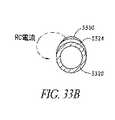
好ましい実施形態において、図33aおよび33bに示されるように、二極性プローブの電極アセンブリは、ステンレス鋼のゲージ20中空針から作製される第1電極3320、およびこの針電極の外部表面状に堆積され、そして付着された伝導性材料(例えば、銀またはニッケル)の層として形成される第2電極3330を備える。薄い電気絶縁器3324は、短い回路を避けるためにそれらの長さに沿って、電極3320、3330を分離する。
【0113】
電極3320、3330は、近位領域から、装置の長手軸3372に沿って延び、この二極性電力は、電極アセンブリの遠位領域に印加される。
【0114】
好ましい実施形態において、第2電極3330は、第1電極3320の回り全体ではなく、第1電極3320の外周の限定部分にわたって延びる。電流は、第2電極3330の外周の比較的小さな部分(ここで、熱が、隣接する組織において発生する)から、第1電極3320の層表面(ここで、熱は、ほとんど発生しない)に向けて流れる。これは、濃密電流を受容する人体の領域に限定され、そして電流が印加されるように、操作者に高い程度の制御を提供する。この第2電極3330は、第1電極の外周の約1/4の弧にわたって延びる。この第2電極3330は、軸3372の回りで対称的に配置される。
【0115】
好ましい実施形態において、この第1電極3320は、洗浄を提供する遠位領域で開口する中心通路3322を有する。洗浄管腔3322は、プローブ先端部の遠位端から、プローブハンドルを通って、コネクターに延び、洗浄能力を提供する。
【0116】
図34は、中実の円柱状の金属部材によって形成される、中心電極または軸方向電極3420、および円筒状の金属管部材によって形成される、細長中空外側電極3430(これは、中心電極の周りに同軸状に位置する)を備える、電極アセンブリの代替の実施形態を示す。電極3430の円筒状の外側表面は、このプローブの周囲表面を形成する。外側電極3430は、好ましくは、強度および伝導性のために、ステンレス鋼または他の耐腐食性伝導性材料から作製される。内側電極3420は、銅から作製され得るが、伝導性がより低い材料もまた使用され得る。これらの電極間の同軸の関係および間隔、ならびにこれらの互いからの絶縁が、これらの電極間の絶縁材料の管状スリーブ3424によって提供され、このプローブアセンブリを完成させる。絶縁体3434のさらなる層が、外側電極3430上に提供されて、この電極の制限された部分のみを、制限された露出領域において、集中したRFエネルギーに曝露し得る。
【0117】
あるいは、絶縁領域3434の1つ以上の領域が、軸に沿った任意の適切な位置で除去されて、電極3430の領域を露出させ得る。次いで、焼灼が、この露出された領域において起こる。第2の電極3430の周囲の範囲は、電流が印加される領域の大きさに対して所望される制御の程度に依存して、さらに制限され得る。
【0118】
図35aおよび35bに示されるような、代替の実施形態において、二極性電極プローブアセンブリの能動領域は、実質的に半円筒状スリーブ3524を管3515上に有する、中空金属管3515によって形成される。金属管3515は電極ではなく、そしてこのプローブアセンブリの強度のためにのみ提供される。先端は、2つの焼灼要素3520、3530を支持する。要素3520、3530の各々は、電気リード線に接続され、これらのリード線は、先端3510の中空の内側を通って、支持用の絶縁ハンドルへと延び、このハンドルにおいて、このリード線は、適切な手段によって、先に記載した様式で、電源に接続される。
【0119】
このプローブは、ハンドルに嵌合する電力コードを介して、低電圧RF電源に接続される。この電源は、高周波数の二極性電源であり得、好ましくは、最小電力設定と最大電力設定との間で連続的に調節可能な、双極性出力を有する固相ユニットである。この電源は、オン/オフスイッチによって作動され、このスイッチは、フットペダルまたはボタンを、プローブまたはインターフェース上に備え得る。この電源は、比較的低い二極性出力電圧を提供する。低電圧電源は、電極先端間のアーク(これは、眼組織を損傷し得る)を回避するために好ましい。RF発生器は、第一および第二の電極に接続されて、生物学的に安全な電圧を、手術部位に印加する。このプローブは、両方の双極性要素(これらの各々が、制限されたRF電流の集中領域を有する)において焼灼するという利点を有する。
【0120】
組織へのエネルギーの送達は、一旦、焼灼要素が所望の位置に配置されると、開始される。エネルギーは、代表的に、導電性リード線を介して、焼灼要素へと送達される。エネルギー源は、好ましくは、RFエネルギーを提供するが、RFに限定されず、そしてマイクロ波、電気、超音波、コヒーレント光および非コヒーレント光の熱移動、ならびに抵抗熱、または当業者に公知のような、他の形態のエネルギーが挙げられ得る。
【0121】
焼灼アクチュエータは、モニタリング回路1744および制御回路1746を備え得(図17)、これらは一緒になって、RF回路の電気パラメータまたはフィードバック制御ループにおける温度のような組織パラメータのいずれかを使用して、焼灼の間、電極要素を通して電流を駆動する。フィードバック制御システムを使用して、選択された視野を所望の温度で所望の時間にわたって維持することによって、所望の加熱の程度を得ることができる。センサ(例えば、熱電対)を使用して、フィードバックループにおける温度をモニタリングし得る。複数の焼灼要素または電極が使用される場合、切換え能力が提供されて、多重のRF電流源を、種々の要素間または電極間で提供し得る。
【0122】
図17は、モニタ回路1744を示し、このモニタ回路は、望ましくは、1つ以上のセンサ(例えば、温度)1740と連絡し、このセンサは、焼灼要素1730の作動をモニタリングする。制御回路1746は、焼灼要素1730を駆動している電流の出力レベルを、感知された条件に基づいて(例えば、モニタリングされた温度と所定の温度設定点との間の関係に基づいて)調節するために、モニタリング回路1744および電源に接続され得る。
【0123】
回路構造、ソフトウェアおよび制御装置へのフィードバック(これらは、完全なプロセス制御を生じる)は、以下を変化させるために使用され得る:(i)電力(RF、非コヒーレント光、マイクロ波、超音波などを含む)、(ii)デューティーサイクル、(iii)単極性または二極性のエネルギー送達、(iv)流体(電解質溶液送達、流速および圧力)、ならびに(v)時間、温度および/またはインピーダンスを介して、切除がいつ完了したかを決定する。
【0124】
好ましい実施形態において、二極性電極は、RF信号発生器、接続ケーブル、眼への挿入のためのプローブ先端部、プローブに取り付けられた接地電極、およびこの接地電極をRF発生器に接続する戻りケーブルを備える回路の一部であり、この回路を完成させる。このようなRF電極は、比較的良導体であるので、電極自体は加熱しない。この電極が接触する組織は、この電極から組織を通る電流に応答して、加熱する。この組織は、回路の残りの部分と比較して比較的伝導性が乏しいので、加熱する。分子の摩擦の結果としてこれらの組織が加熱するのは、熱が次いで電極自体に伝導されて戻る場合である。この時点で、熱電対は、温度の上昇を感知し、そしてその情報をRF発生器に供給し、その結果、温度の制御を達成するために、フィードバック機構が、送達されるエネルギーを減衰させ得る。
【0125】
温度とインピーダンスとの両方のモニタリングによって、RF送達を調節することもまた、有利であり得る。洗浄流体の流れをモニタリングして、その部位の清浄性を維持することもまた、有利であり得る。RFと、手術部位への洗浄流体到達との間の相乗効果が、例えば、その部位における温度のより高レベルでの制御を提供する機会もまた、存在する。
【0126】
制御装置は、RF発生器、温度プロフィール、温度調節器、温度モニタ、手術器具、インピーダンスモニタ、インピーダンス調節器、ポンプ、流体調節器、および流れモニタを備え得る。
【0127】
RF発生器は、単極電力または二極電力を、プローブに送達し得る。このプローブは、手術部位に位置する。インピーダンスモニタは、例えば、電流および電圧を測定し、そしてRMS計算を実行することによって、インピーダンス測定値を得る。インピーダンスモニタの測定値は、インピーダンス調節器に送達される。インピーダンス調節器は、いくつかの機能を実行する。一般に、インピーダンス調節器は、RF発生器によって供給される電力を制御することによって、インピーダンスレベルを、受容可能な限度に維持する。本発明の1つの実施形態において、このインピーダンス調節器は、より多くの、より少ない洗浄流体を手術部位に送達するように、流れ調節器を制御し得る。
【0128】
組織を焼灼するために適切な温度を維持するために、このプローブの遠位先端はまた、熱電対1740を備え得る。タイミングデバイスと組み合わせられた温度フィードバックは、正確な程度の焼灼が送達されることを可能にし、いかなる眼内の加熱も引き起こさずに、所望の効果を得る。組織に対する加熱効果は、前眼房を深くするための粘弾性薬剤を用いて緩和され得る。
【0129】
図17を参照すると、温度モニタ1744は、1つ以上の型の温度センサ(例えば、熱電対、サーミスタ、抵抗型温度デバイス(RTD)、赤外検出器など)を備え得る。
【0130】
熱電対に対する適切な形状としては、ループ、重なったループ、「T」字構成、「S」字構成、フック構成、または球状の構成が挙げられるが、これらに限定されない。これらの形状は、熱電対を長くすることなく、熱電対のより大きな表面積を提供する。真っ直ぐな熱電対より大きな露出領域を有する、これらの熱電対は、より良好な正確さおよび応答時間を有すると考えられる。この熱電対は、ファスナーによって取り付けられる。このファスナーは、接着剤(例えば、エポキシ、シアノアクリレート接着剤、シリコーン接着剤、可撓性接着剤などが挙げられるが、これらに限定されない)のビーズであり得る。複数の熱電対を異なる位置に提供し、そしてこれらの作動パラメータ(例えば、応答時間などを比較することもまた、望ましくあり得る。この比較は、このような特定の変数がフィルタリングされ、その結果、熱電対の位置における正確な温度を計算することを可能にするための、有用な情報を提供し得る。
【0131】
温度モニタ1744の出力は、温度調節器1746に送達される。温度調節器1746は、RF発生器1760と流れ調節器との両方を制御し得る。例えば、温度が認容可能な限度を超えて上昇した場合、RF発生器によって手術器具へと供給される電力が、低下され得る。あるいは、温度調節器によって、流れ調節器が洗浄流体を増加させ得、これによって、手術部位における温度を低下させ得る。逆に、測定された温度が所望の温度に適合しない場合、温度調節器は、RF発生器または流れ調節器のいずれかと、インターフェースし得る。流れ調節器は、ポンプとインターフェースして、手術部位に送達される洗浄流体の容量を制御する。
【0132】
本発明のプローブを用いて、Schlemmectomyを実施するための手順は、先に記載された伝統的な線維柱帯切開術と類似である。医師は、好ましくは、手術顕微鏡を利用して、手術室のテーブルの横側に座る。側頭下(infrotemporal)円蓋に基づく結膜の弁が作製され、そして結膜およびトノン嚢が、後方に移動される。三角形の弁が作製され、そして表面の弁が、角膜内に移動される。半径方向の切開が、シュレム管に作製され、これによって、この管内への入口を作製する。好ましくは、Vanna鋏がシュレム管に導入され、この管を、各側において約1mm開く。透明な角膜の挿入(parenthesis)が実施され、そして前眼房が、好ましくはHaelon GVを用いて深くされる。プローブが、シュレム管に下から導入される。この器具はここで、深くされた前眼房内に焼灼要素が面するように、整列される。あるいは、焼灼表面は、小柱網に面し、そして前眼房内へのプローブの回転の時点に、フットスイッチによって作動される。次いで、このフットスイッチは、焼灼を活性化するために使用され得る。吸引および洗浄もまた、このフットスイッチを使用して作動され得る。線維柱帯切開器具は、前眼房内へとゆっくりと回転され、そして線維柱帯切開器具の刃が前眼房内に見えるとき、焼灼(ならびに吸引および/または洗浄)が停止される。シュレム管の上位の局面は、逆の曲率を有する線維柱帯切開器具を用いて入れられ得る。同じ工程に続いて、小柱網の大部分が取り除かれる。好ましい実施形態において、小柱網のかなりの部分(好ましくは、少なくとも半分)が、取り除かれる。線維柱帯切開器具を取り除いた後に、上行線維柱帯切開弁を、縫合糸を使用して縫合により閉じる。
【0133】
電波手術は、熱ではなく高周波数の電波を使用して、燃焼効果(これは、伝統的な電気手術デバイスおよび焼灼装置において共通である)なしで組織を切断および凝固する。電波エネルギーの広がりに対する組織の抵抗は細胞内で熱を発生させ、この細胞内の水を気化させ、そして他の細胞層を損傷させることなく、その細胞を破壊する。
【0134】
本発明の特定の形態が記載されたが、本発明の精神および範囲から逸脱することなく、種々の改変が、なされ得ることが、明らかである。従って、添付の特許請求の範囲による以外には、本発明が限定されることは意図されない。
【図面の簡単な説明】
【0135】
【図1】図1は、ヒトの眼の横断断面模式図である。
【図2】図2は、ヒトの眼の前眼房へ、そして前眼房を通る眼房水の流れを示す横断断面模式図である。
【図3】図3a〜dは、緑内障における強膜篩板の変形の進行を模式的に示す。
【図4】図4a〜cは、隅角切開を行う工程を模式的に示す。
【図5】図5a〜dは、小柱透析(trabeculodialysis)を行う工程を模式的に示す。
【図6】図6a〜eは、好ましい実施形態のプローブを使用した線維柱帯切開術手順の工程を模式的に示す。
【図7】図7は、好ましい実施形態の隅角切開焼灼プローブを示す斜視図である。
【図8】図8は、図7の隅角切開焼灼プローブを示す横断断面模式図である。
【図9】図9は、図7の隅角切開焼灼プローブの別の実施形態を示す横断断面模式図である。
【図10a】図10aは、図7の隅角切開焼灼プローブのプローブ先端部を示す詳細図である。
【図10b】図10bは、図7の隅角切開焼灼プローブのプローブ先端部を示す横断断面模式図である。
【図11a】図11aは、図7の隅角切開焼灼プローブのプローブ先端部を示す詳細図である。
【図11b】図11bは、図7の隅角切開焼灼プローブのプローブ先端部を示す横断断面模式図である。
【図12a】図12aは、図7の隅角切開焼灼プローブのプローブ先端部を示す詳細図である。
【図12b】図12bは、図7の隅角切開焼灼プローブのプローブ先端部を示す横断断面模式図である。
【図13】図13は、好ましい実施形態の隅角切開焼灼プローブを示す斜視図である。
【図14】図14は、好ましい実施形態の隅角切開焼灼プローブを示す斜視図である。
【図15a】図15aは、図13の隅角切開焼灼プローブのプローブ先端部を示す詳細図である。
【図15b】図15bは、図13の隅角切開焼灼プローブのプローブ先端部を示す横断断面模式図である。
【図16a】図16aは、図14の焼灼プローブのプローブ先端部を示す詳細図である。
【図16b】図16bは、図14の焼灼プローブのプローブ先端部を示す横断断面模式図である。
【図17】図17は、隅角切開プローブの好ましい実施形態の模式回路図を示す。
【図18】図18は、隅角切開プローブを示す斜視図である。
【図19】図19は、図18のプローブの実施形態を示す横断断面模式図である。
【図20】図20は、図18のプローブの実施形態を示す横断断面模式図である。
【図21】図21は、図18のプローブの実施形態を示す横断断面模式図である。
【図22】図22は、図18のプローブの実施形態を示す横断断面模式図である。
【図23】図23は、図18のプローブの実施形態を示す横断断面模式図である。
【図24a】図24aは、レーザー隅角切開プローブの好ましい実施形態を示す斜視図である。
【図24b】図24bは、レーザー隅角切開プローブの好ましい実施形態を示す斜視図である。
【図25】図25は、図24aのレーザー隅角切開プローブの横断断面模式図である。
【図26】図26は、図24bのレーザー隅角切開プローブの横断断面模式図である。
【図27】図27は、図24bのレーザー隅角切開プローブの横断断面模式図である。
【図28】図28は、好ましい実施形態のシュレム管除去プローブを示す斜視図である。
【図29】図29a〜cは、図28のプローブのプローブ先端部を示す詳細図である。
【図30】図30は、図28のプローブの代替的な好ましい実施形態の斜視図である。
【図31】図31a、b、cは、図30のプローブのプローブ先端部の詳細図である。
【図32】図32a、bは、図30のプローブのプローブ先端部を示す詳細図である。
【図33a】図33aは、図30のプローブのプローブ先端部を示す詳細図である。
【図33b】図33bは、図30のプローブのプローブ先端部を示す横断断面模式図である。
【図34a】図34aは、図30のプローブのプローブ先端部を示す詳細図である。
【図34b】図34bは、図30のプローブのプローブ先端部を示す横断断面模式図である。
【図35a】図35aは、図30のプローブのプローブ先端部を示す詳細図である。
【図35b】図35bは、図30のプローブのプローブ先端部を示す横断断面模式図である。【Technical field】
[0001]
(Background of the Invention)
(Field of the Invention)
The present invention relates to novel glaucoma surgical instruments and methods. In particular, the present invention relates to the removal of trabecular meshwork by mechanical cautery, vapor therapy, or other tissue disruption means (optionally connected to equipment with inhalation, suction, and footplates) About.
[Background Art]
[0002]
(Explanation of related technology)
Aqueous is a clear, colorless liquid that fills the anterior and posterior chambers. Aqueous humor is formed by the ciliary body of the eye and supplies nutrients to the lens and cornea. In addition, the aqueous humor provides a continuous stream from which surrounding tissues can drain metabolic waste.
[0003]
The aqueous humor generated in the ciliary process circulates through the pupil from the posterior chamber to the anterior chamber and is absorbed through the trabecular meshwork (a plurality of crossed collagen cords covered by endothelium). Once through the trabecular meshwork, aqueous humor passes through the sclera through Schlemm's canal and into a collector channel that passes into the venous circulation above the sclera. The production rate in a normal eye is typically 2.1 μL / min. Intraocular pressure in the eye is maintained by the formation and drainage of aqueous humor. All tissue within the corneal sclera covering the eyeball is subjected to this pressure, which is higher than the pressure applied to the tissue elsewhere in the body.
[0004]
Glaucoma is a group of diseases characterized by progressive atrophy of the optic disc, causing loss of visual field and eventually blindness. Glaucoma is generally associated with increased intraocular pressure, which is a significant risk factor for visual field loss, as it causes additional damage to optic nerve fibers. Another factor in glaucoma may be that nerves are particularly vulnerable to pressure due to local lack of circulation, tissue weakness, or structural abnormalities. In "normal" eyes, intraocular pressure is in the range of 10-21 mmHg. In glaucoma eyes, this pressure can rise to 75 mmHg.
[0005]
There are several types of glaucoma, including open-angle glaucoma and closed-angle glaucoma, mainly due to obstruction of aqueous outflow from the eye (or, rarely, aqueous humor in the eye). With an abnormal increase in intraocular pressure (due to overproduction of The most prevalent form is primary open-angle glaucoma, in which aqueous humor has free access to the iridocorneal angle, while drainage of aqueous humor is small. Damaged through disturbance of the pillar network. In contrast, in angle-closure glaucoma, the even angle is closed by the peripheral iris. Angle blocks can usually be corrected by surgery. Less prevalent forms of glaucoma include secondary glaucoma associated with inflammation, trauma, and bleeding.
[0006]
Aqueous humor is similar to plasma in terms of electrolyte composition, but has a lower protein content. The aqueous humor keeps the eye inflated, supplies the nutrients required by the vascular lens and cornea, and flushes out metabolites and toxic substances in the eye. The bulk of aqueous humor formation is the active cells by nonpigmented epithelial cells of the ciliary process from the transport of active solutes (probably sodium), followed by the osmotic flow of water from the plasma. It is a product of sexual secretion. The pigment-free epithelial cells of the ciliary process are connected at their apical cell membranes by tight connections. These cells are involved in the formation of the blood / aqueous barrier, and large molecules (including proteins) from the blood-bone do not cross the blood / aqueous barrier.
[0007]
Intraocular pressure (IOP) is a function of the difference between the rate at which aqueous humor enters and leaves the eye. Aqueous humor enters the posterior chamber by three means: 1) active secretion of ciliary processes by pigment-free epithelial cells; 2) ultrafiltration of blood plasma; and 3) diffusion. The newly formed aqueous humor flows out of the posterior chamber around the lens and flows through the pupil into the anterior chamber; aqueous humor is 1) evenly due to uveoscleral outflow. Leave the eye by passive bulk flow at the corner, or 2) active transport through the trabecular meshwork, especially the paratubular segment. Any change in 1), 2), or 3) can disrupt aqueous humor dynamics and alter intraocular pressure.
[0008]
Primary open-angle glaucoma is caused by obstructions in the trabecular meshwork. This increases intraocular pressure. This major obstruction occurs in the juxta-canalicular portion located adjacent to Schlemm's canal. In infants, corner or trabeculotomy can be performed. In a corner or trabeculotomy, a small needle or probe is introduced into Schlemm's canal, and the trabecular meshwork is mechanically disrupted into the anterior chamber. About 90 ° to 120 ° of the trabecular meshwork can be destroyed. The anatomical difference between congenital glaucoma and adult glaucoma is that in congenital glaucoma, once ciliary muscle fibers have penetrated the trabecular meshwork and, once broken, the trabecular meshwork is pulled backwards. To allow fluid to penetrate Schlemm's canal and be removed through normal collector channels present in the wall of Schlemm's canal. In adults, the trabecular meshwork is split but remains intact and reattaches to the posterior scleral wall of Schlemm's canal, which blocks the collector channel.
[0009]
Most glaucoma procedures focus on reducing intraocular pressure. This treatment may include administration of a beta blocker (e.g., timolol) to reduce aqueous humor production, administration of an adrenergic agonist to reduce intraocular pressure, or diuretics (e.g., Acetoazolamide), miotic eye drops (eg, pilocarpine) to promote aqueous outflow, or prostaglandin analogs to increase uveoscleritis outflow . If drug treatment is ineffective and the patient's vision faces danger, acute forms of glaucoma may require peripheral iridotomy to relieve pressure. Other forms of treatment generally involve physical or thermal destruction of the ciliary body of the eye ("ciliary destruction") by surgery or the application of laser beams, cryogenic liquids, or high frequency ultrasound. ).
[0010]
In a monitored filtration surgery (fence woven cut), the fistula created through the limb sclera is overlaid with an overlying partial suturing scleral flap. Protected. This scleral flap provides additional resistance to excessive loss of aqueous humor from the eye, thereby reducing the risk of early postoperative hypotonicity.
[0011]
According to one recently introduced procedure, a sufficiently thick filtration fistula can be made with a holmium laser probe, leaving minimal surgically induced trauma. After postbulbar anesthesia, a conjunctival incision (about 1 mm) is made about 12-15 mm posterior to the intended sclerotomy site, and the laser probe is advanced through the subconjunctival space to the rim. Multiple laser pulses are then applied until a fistula of sufficient thickness is created. This technique sometimes causes premature hypotonicity due to the difficulty in controlling the size of the sclerotomy. Furthermore, iris prolapse into early and late sclerotomy causes abrupt closure of the filter, ultimately leading to surgical failure. Further, despite its relative simplicity, a disadvantage of this procedure and other types of glaucoma filtration is the tendency of the filtel to be closed by wounds.
[0012]
Various attempts have been made to overcome the problems of filtration surgery (eg, by using ophthalmic implants such as the Baerveldt Glaucoma Implant). Typical ophthalmic implants use a drain to maintain the integrity of the opening formed in the eye for the opening of the IOP.
[0013]
Typical ophthalmic implants suffer from several disadvantages. For example, the implant may use a valve mechanism to regulate the flow of aqueous humor from the eye; disadvantages and / or failures of such a valve mechanism may result in excessive loss of aqueous humor from the eye and Generates the possibility of hypotonicity. The implant also tends to clog the eye over time, either from the inside with tissue (eg, the iris) aspirated into the entrance or from the outside, eg, due to cell growth due to wounding. In addition, typical implant insertion procedures are complex, expensive, time consuming, and leave complex glaucoma problems.
[0014]
However, there are many problems in effectively treating glaucoma with long-term medical and surgical therapies. One problem is the difficulty in inventing means for producing pharmacologically effective intraocular concentrations and preventing extraocular side effects induced by systemic administration. Many drugs are administered topically or locally. However, the amount of drug that enters the eye is only a few percent of the topically applied dose. Ocular tissues are protected from such substances by a number of mechanisms, including tear turnover, blinking, conjunctival absorption into the systemic circulation, and a highly selective corneal barrier. Because there is.
[0015]
Pharmacological treatment is very expensive for the majority of glaucoma patients. In addition, many people with the disease live in remote, underdeveloped areas where drugs are not readily available. The drugs used in this treatment have undesirable side effects, and many of the long-term effects resulting from long-term use are not yet known. 25% of patients do not use these medications accurately.
[0016]
Glaucoma is a disease that gets progressively worse, which may require filtration surgery to control intraocular pressure. The current surgical techniques for reducing intraocular pressure when medication fails to reduce fluid flow into the eye or increase fluid outflow include anterior chamber and episcleral / By creating a fluid passageway between the supra-scleral / sub-Tenon's space, fluid can enter the extraocular position or into or through Schlemm's canal to allow fluid to flow into the eye. (Eg, U.S. Pat. No. 4,846,172). The most common glaucoma surgery is glaucoma filtration surgery, especially trabeculectomy. These operations involve the creation of a fistula between the subconjunctival space and the anterior chamber. This fistula creates a hole in the rim either by cutting away a portion of the limb tissue with either a blunt knife or by burning through the subconjunctival space into the anterior chamber. Can be produced. The fluid is then filtered through the fistula and absorbed by the sclera and conjunctiva. The fistula must be substantially non-obstructive for the surgery to be effective. However, these drainage or filtration procedures often fail due to passage closure due to healing of large wounds created to increase access to the surgical site. Failures are often due to wounds at the site of the incision in the conjunctiva and Thonon's capsule. The surgery fails immediately in at least 15% of patients and in higher rates in the long term. Currently, this result of trabeculectomy (closed passages) is treated with 5-fluorouracil and mitomycin_C, which apparently prevent closure by inhibiting cell proliferation. However, these drugs are very toxic and have undesirable side effects, including scleral dissolution, hypotonia, leakage, and late infection.
[0017]
Other surgical procedures have been developed in an attempt to treat glaucoma victims. Iridectomy (removal of a portion of the iris) is often used in angle closure glaucoma where there is obstruction of the trabecular meshwork by iris contact. Removal of a portion of the iris then provides an aqueous free passage from the posterior chamber to the anterior chamber in the eye. Ocular tissue can grow back to the pre-operative state, thereby requiring the need for further treatment.
[0018]
Thus, there is a need to develop more effective glaucoma treatments in view of the limited effectiveness of treatment options.
DISCLOSURE OF THE INVENTION
[Means for Solving the Problems]
[0019]
(Summary of the Invention)
SUMMARY OF THE INVENTION The present invention is a surgical device that removes at least a portion of the trabecular meshwork of the eye and provides aqueous drainage in the treatment of glaucoma and a surgical method that minimizes invasiveness.
[0020]
A preferred embodiment of the present invention involves inserting a surgical instrument through a small corneal incision to excise the trabecular meshwork while visually observing through a camera. The device may include a foot plate that can penetrate the trabecular meshwork into Schlemm's canal. This footplate also acts as a protective device for endothelial cells and as an aggregation channel lining the scleral wall of Schlemm's canal. The device may also include an infusion system and an inhalation system. Infusion is maintained and the anterior chamber is lowered so that easy access of the eye's angle to the trabecular meshwork and Schlemm's canal is obtained. The infusion also allows the surgeon to drain the fluid into the collecting channel while performing the operation, thus leaving the surgical field free of blood. Aspiration is designed to remove excised tissue, gas and foam formation, and any resulting intraocular debris. The suction may be coupled directly to either a cutting mechanism (eg, a cutter, laser probe, piezo-crystal generating sound source or piezo-crystal generating ultrasound source) or ablation element. These modalities allow for substantially complete tissue removal by mechanical means, ablation, evaporation, or other tissue disruption techniques.
[0021]
The surgical instrument performs a goniectomy procedure by removing a portion of the trabecular meshwork consisting of pigmented trabecular meshwork, from the anterior chamber to the scleral part of Schlemm's canal (endothelial cells and most importantly). Are used to allow free access to aqueous humor (including the collecting channel returning to the scleral venous system).
[0022]
In another embodiment, a Schlemm's canal removal surgical procedure similar to trabeculotomy, a Schlemm's canal removal probe is inserted into Schlemm's canal macroscopically during sclerectomy. As a result, tissue with the surface of the device facing the trabecular meshwork, including the pigmented trabecular meshwork facing Schlemm's canal, and a portion of the ungranulated trabecular meshwork, can be ablated, radiofrequency electrodes, or piezoelectric crystals. Removed by an ultrasonic transducer formed from
[0023]
This device is advantageous because it combines existing procedures with new technologies and provides a simple solution for glaucoma treatment.
[0024]
(Detailed description of preferred embodiments)
Referring to FIG. 1, the relevant structures of the eye are briefly described to provide a context for the anatomical terms used herein. Certain anatomical details are well known to those skilled in the art and have been omitted for clarity and convenience.
[0025]
As shown in FIG. 1, the cornea 103 is the outer part of the eye and is a thin transparent film on the front of the iris 104. The cornea 103 is connected to the sclera 102 at a junction referred to as the rim 108. A layer of tissue called the bulbar conjunctiva 106 covers the exterior of the sclera 102. The bulbar conjunctiva 106 is the thinnest on the anterior side of the rim 108 and is a thin epithelial layer extending from above the cornea 103 to the corneal epithelium. The bulbar conjunctiva 106 has a substantially large amount of fibrous tissue as it extends posteriorly. The bulbar conjunctiva 106 descends into the Thonon's capsule about 3 mm above the rim 108. The Thonon's capsule is a thicker, more substantial encapsulating tissue that covers the rest of the eyeball. The subconjunctival and sub-tonon space is the space where these two tissues approach at about 3 mm from the margin. The ciliary body or ciliary projection 110 is part of the ocular vascular membrane. This begins at the rim 108 and extends along the interior of the sclera 102. The choroid 112 is a vascular membrane that extends along the posterior side of the retina toward the optic nerve. The anterior chamber 114 is the space between the cornea 103 and the crystalline lens 116 of the eye. The lens of the eye is located between the iris 104 and the vitreous body 120 and is wrapped in a transparent membrane called the lens capsule 122. The anterior chamber 114 is filled with aqueous humor 118. The trabecular meshwork 121 drains excess aqueous humor 118 from the anterior chamber 114 through the Schlemm's canal 124 into the collecting channel, which combines with the veins carrying blood to remove aqueous humor 118 from the eye. Remove.
[0026]
As shown in FIG. 2, aqueous humor 118 flows from the posterior chamber through the pupil to the anterior chamber 114.
[0027]
Figures 3a-d show longitudinal sections through the optic nerve head, showing progressive deepening of the optic cup 302 in the glaucomatous nerve head advanced from normal. FIG. 3a shows normal nerves, and FIG. 3d shows the affected nerves in advanced glaucoma. As the optic cup 302 collapses and the scleral phloem 306 becomes more curved, axons 304 passing through the scleral phloem 306 will be subjected to bending and pressure as they progress through the scleral phloem 306. .
[0028]
(Corner incision)
4a-c show the steps for performing a corner dissection procedure. As shown in FIG. 4a, fixation forceps 406 are typically used to grab the inferior and superior rectus muscles. Corner-cut lens 408 is placed on the eye. A corner-cutting knife 400 is inserted from the temporal side below this corner-cutting lens and viewed with a microscope. The cornea is washed with a balanced salt solution. The surgeon places the corner dissection lens 408 over the cornea and holds the lens 408 with angled toothed forceps 406 located in two recesses at the top of the lens 408.
[0029]
The surgeon places a corner dissection knife 400 1.0 mm anterior to the rim and passes it through the cornea, keeping the knife 400 parallel to the plane of the iris (FIG. 4b). The slight rotation of this knife 400 facilitates a smooth penetration into the anterior chamber without suddenly breaking through the cornea. The surgeon gradually applies pressure and continues to rotate the corner dissecting knife 400, moving the knife across the anterior chamber until the trabecular meshwork has reached a diagonal position and against the plane of the iris. Orient parallel.
[0030]
The surgeon visualizes the trabecular meshwork directly with a microscope and engages the shallow layer of the trabecular meshwork at the midpoint of the trabecular meshwork. The incision is typically made around 100 ° -120 ° with a first clockwise 50 ° -60 ° incision and then a counterclockwise 50 ° -60 ° incision.
[0031]
When the tissue is dissected, a white line can be observed, and the iris usually falls posteriorly. The assistant facilitates the incision by rotating the eye in the opposite direction of the action of the blade (FIG. 4c).
[0032]
The surgeon completes the corner incision and removes the blade immediately. If the escape of water from the wound and tuft is shallow, the surgeon may slide the corner dissection lens over the incision when removing this blade. The anterior chamber can be reformed by injecting a balanced salt solution through the outer edge of the corneal incision. This leakage can be stopped using sutures and burying the ligature.
[0033]
(Fibrous trabecular stripping)
Trabeculectomy is similar to gonitomy, except firstly in young patients with glaucoma and secondly in patients with inflammation. Trabeculectomy differs from corner incision only at the location of the incision. 5a-d show the steps of the trabecular meshwork stripping procedure. Knife 500 passes through the anterior chamber of the eye and engages the trabecular meshwork at the Schwalbe line rather than midline of the trabecular meshwork, as shown in FIG. 5a.
[0034]
The incision is typically made in the surrounding 100 ° -120 °, first incising 50 ° -60 ° clockwise and then counterclockwise 50 ° -60 ° (FIG. 5b).
[0035]
Using the flat side of the blade, the surgeon pushes the trabecular meshwork downward toward the surface of the iris, as shown in FIG. 5c. FIG. 6d shows the trabecular meshwork removed from the scleral groove and exposing the outer wall of Schlemm's canal.
[0036]
(Trabeculotomy)
Trabeculotomy displaces the trabecular meshwork as a barrier to water outflow. First, the surgeon creates a triangular scleral flap 604 that is dissected from the front of the rim, as shown in FIG. 6a. A radial incision is made on the predicted site of Schlemm's canal (FIG. 6b). This incision deepens until the Schlemm's canal lid is opened (FIG. 6c).
[0037]
The surgeon places the Schlemm's canal over the outer surface of the rim, passes the trabeculotome through the tubing, and rotates the instrument into the anterior chamber, as shown in FIG. 6d. The upper arm 610 of the instrument must be held parallel to the plane of the iris. The device 600 is then rotated in the anterior chamber and kept parallel to the iris. After rotating the instrument 600 through the trabecular meshwork in one direction, the surgeon removes the instrument and inserts a second instrument having the opposite curve. Then the same procedure is performed in the opposite direction.
[0038]
During this procedure, collapse of the anterior chamber often occurs. The anterior chamber can be reformed by injecting a cleaning fluid. Aspiration can be used to remove the tissue. Scleral valve 604 is then sutured closed as shown in FIG. 6e.
[0039]
(Gonitomy cautery probe)
A preferred embodiment of a goniectomy probe used to cauterize and ablate the trabecular meshwork is shown in FIGS. The probe 700 includes a handle 705 and a probe tip 710. Preferably, the handle is about 20 gauge and the probe tip is about 27 gauge. The proximal end of the handle is adapted to mate connector 712 with the output end of energy source 760.
[0040]
The probe also includes electrical leads 834 (FIG. 8), power cables 708 (preferably coaxial cables), and actuation means. These components extend from the handle 705 through the electrical lead lumen 832 (FIG. 8) in the probe shaft 705 to the corresponding components of the probe 700 located on the distal end. The proximal end and lumen of the cable are connected to corresponding connectors extending from the distal end of probe handle 705.
[0041]
Suction and irrigation may be provided by suction pump 770 and irrigation pump 780. The suction pump 770 is connected to a standard vacuum supply line to facilitate removal of suction fluid. Suction vacuum control is provided by a suction valve. In a preferred embodiment, as shown in FIG. 8, both irrigation and aspiration can be provided by the same lumen 822, optionally with alternating pumps. However, irrigation lumen 922 and aspiration lumen 924 are separate and provide simultaneous irrigation and aspiration in the embodiment of FIG. Irrigation under pressure flushes blood from the eye and widens the anterior chamber, further providing room for this procedure.
[0042]
Handle 705 may be made of an electrically insulating polymer material and is configured in a pencil-type configuration having a cylindrical body region 702 and a tapered front region 704. The contoured handle helps reduce the required holding force and increase the intrinsic sensitivity. Although a pencil-type configuration is preferred, any configuration of the handle 705 that is easily, comfortably and conveniently gripped by an operator has also been shown to be suitable and is construed as being within the scope of the invention.
[0043]
Probe tip 710 is connected to the main body of handle 705. The probe tip further comprises a footplate 721, which protects the controller channel, penetrates the trabecular meshwork, and serves as a guide in Schlemm's canal. The ablation element 730 located at the distal end of the probe tip 710 can have various configurations.
[0044]
The tip 710 can be any material, for example, titanium, brass, nickel, aluminum, stainless steel, other types of steel, or alloys. Alternatively, non-metallic materials, such as certain plastics, can also be used. The malleable probe tip is configured, for example, as a straight, angled or curved configuration, which provides optimal access to certain anatomical structures and pathologies. The unique tip design improves tactile feedback for optimal control and access, and provides improved tissue visualization with greatly reduced foaming or carbonization.
[0045]
Probe tip 710 includes electrodes 730 suitable for ablation, as is known to those skilled in the art. Various electrode configurations and shapes may be appropriate. The ablation element 730 can be any electrode that can provide ablation or ablation of tissue, such as an ultrasonic transducer, RF electrode or any other suitable electrode.
[0046]
The ablation element may also comprise other sources of ablation energy or a sink, in particular a thermal conductor. Examples of suitable thermal conductor arrangements include, for example, metal elements that can be configured as described above. However, in embodiments of the thermal conductor, such metal elements are generally resistively heated in a closed loop circuit internal to the probe, or conductive by a heat source connected to the thermal conductor. Heated.
[0047]
The probe tip may have a coating (eg, a coating comprising non-stick plastic or diamond) to prevent unwanted sticking or carbonization of tissue. The electrode may be provided on the inner surface of the tip. Alternatively, the electrode is embedded in the sheath of the tube. Insulation is provided around the ablation element so that other areas of the eye are not affected by the ablation. A sleeve shield or non-conductive layer is provided on the probe tip to expose only selected portions of this electrode. The sleeve preferably has a thickness sufficient to prevent both current and capacitance from coupling to tissue.
[0048]
The electrodes or other devices used to deliver energy can be made from a number of different materials, including but not limited to stainless steel, platinum, other noble metals, and the like. The electrode may also be made from a shape memory metal (eg, nickel titanium). The electrode may also be made from a composite, whereby different parts are composed of different materials.
[0049]
In a preferred embodiment, the probe assembly is bipolar. In a bipolar system, two electrodes of opposite polarity are placed on the probe tip, thus eliminating the contact plate for circuit completion. Further, multiple pairs of electrodes can be provided on the probe tip.
[0050]
In an alternative embodiment, the probe assembly is unipolar. In a monopolar system, the system comprises a single electrode, and the contact plate is attached to the surface of the human body. This contact plate is further connected via a lead to the negative terminal of the power supply. A voltage of opposite polarity is applied to this electrode and the contact plate.
[0051]
In a preferred embodiment, as shown in FIGS. 10a and 10b, the electrode assembly of the bipolar probe has one electrode 1020 made from a stainless steel 20 gauge hollow needle, and vapor deposited on the outer surface of the needle electrode 1020. And a second electrode 1030 formed thereon as a layer of a conductive material (eg, silver or nickel) adhered thereto. The thin electrical insulator 1028 separates the electrodes 1020, 1030 along their length to avoid short circuits.
[0052]
The electrode 1020 extends along the longitudinal axis 1072 of the footplate 721 (FIG. 7) from a proximal region where bipolar power is applied to a distal region of the electrode assembly.
[0053]
In a preferred embodiment, the second electrode 1030 extends over a limited portion of the perimeter of the first electrode 1020 rather than all around the first electrode. Current flows around this first electrode 1020 and a relatively small portion of its length. This limits the area in the body that receives the current and provides the operator with a high degree of control over where the current is applied. The second electrode 1030 extends over about a quarter arc around the first electrode 1020. This second electrode 1030 is symmetrically arranged around axis 1072.
[0054]
In a preferred embodiment, the first electrode, and thus the footplate 721, has an open central passage 1022 in the distal region to provide irrigation and suction. The irrigation and aspiration lumen extends from the distal end of the probe tip 1010, through the probe handle to the connector, and provides irrigation and aspiration capability.
[0055]
In the embodiment shown in FIGS. 11a and 11b, the electrode assembly comprises a central or axial electrode 1120 formed by a solid cylindrical metal member and an elongated hollow outer electrode 1130 formed by a cylindrical metal tube member, which comprises , Disposed coaxially around the center electrode 1120). The cylindrical outer surface of electrode 1130 forms the circumferential surface of the probe. Outer electrode 1130 is preferably made of stainless steel or other corrosion resistant conductive material for strength and conductivity. Inner electrode 1120 may be made of copper, but less conductive materials may also be used. The coaxial relationship and spacing between electrodes 1120 and 1130, and their electrical isolation from each other, is provided by a tubular sleeve 1128 of electrically insulating material between the electrodes.
[0056]
Insulating layer 1132 may also surround second electrode 1130. One or more regions of the insulating region 1132 may be removed at any suitable location along its axis to expose regions of the electrode 1130. Cauterization occurs in the exposed areas. The circumferential range of the second electrode 1130 may be further limited, depending on the degree of control desired over the size of the area where the current is applied.
[0057]
In an alternative embodiment, as shown in FIG. 12, the active area at the remote end of the bipolar electrode is formed by a hollow metal tube 1200, which has a hollow metal tube 1200 on its outer surface. It has a substantially cylindrical insulating layer 1228. The metal tube 1200 is provided only for the strength of the probe assembly, not the electrodes. The tip supports two metal electrodes 1230, 1240. Each of the electrodes 1230, 1240 has a conductor that extends through the hollow interior of the tube 1200 to a supporting insulated handle, where the conductor is connected to a power source and appropriate means in the manner previously described. Connected by Energy flows between the electrodes 1230 and 1240, heating only the tissue adjacent to the gap between them. Aspiration and irrigation may be provided through lumen 1222.
[0058]
13 and 14 show an alternative embodiment of a goniectomy ablation probe 1300, 1400. The probe includes handles 1305, 1405 and probe tips 1310, 1410. The probe tip comprises cautery elements 1330, 1430.
[0059]
Probes 1300, 1400 comprise an energy source; however, probe 1400 also comprises a wash supply 1480 and a suction pump 1470. These components connect to probes 1300, 1400 at connectors 1308, 1408.
[0060]
15a, b show a detailed view of the probe tip 1310. The probe tip 1510 is straight and comprises electrodes 1530 attached to electrodes 1520, which are separated by an insulating layer 1528.
[0061]
16a, b show a detailed view of the probe tip 1410. The probe tip 1610 is straight and comprises electrodes 1630 attached to hollow electrodes 1620, which are separated by an insulating layer 1628. Hollow electrode 1620 forms a hollow passage for cleaning and suction.
[0062]
In an alternative embodiment, the needle tip of FIG. 14 comprises a hollow needle, with or without a cautery element, acoustically connected to an ultrasonic handle and surrounded by a hollow sleeve. The handle is equipped with an ultrasonic transducer (eg, used for ultrasonic emulsification), which can be either piezoelectric or magnetostrictive. When the handle is activated, the needle oscillates longitudinally at ultrasonic velocity. At the same time, a hydrodynamic flow of irrigation fluid can be introduced into the eye. The oscillating needle emulsifies the tissue and the particles are simultaneously aspirated from the eye, preferably with the fluid, through the hollow needle tip. Suction is provided by a vacuum pump, which is connected to a handle. An ultrasonically vibrating needle emulsifies tissue by combining the following: i) the mechanical impact of the needle tip that changes depending on its mass, sharpness, and acceleration; ii) produced by the metal surface of the vibrating needle. Iii) fluid waves created at the leading edge of the needle, and iv) implosion of the ablation bubble created at the tip of the oscillating needle.
[0063]
In an alternative embodiment, acoustic techniques may be used to ablate the tissue. Acoustic technology provides an innovative means of removing material without the production of heat and cavitation energy by using sonic technology rather than ultrasonic technology. The tip expands and contracts, generating heat at the tip due to intermolecular frictional forces, which can be conducted to surrounding tissue. If sonic energy is used to remove the trabecular meshwork, the tip does not require a hollow sleeve.
[0064]
The use of sonic energy, and in particular, ultrasonic energy, offers the advantage of simultaneously applying a dose of energy sufficient to ablate the area without exposing the eye to electrical current. The ultrasonic driver may also adjust the drive frequency and / or change the power to smooth or unify the generated parallel ultrasonic beam.
[0065]
The amount of heat generated is directly proportional to the operating frequency. The sonic tip does not produce a cavitation effect, and thus a true fragmentation rather than emulsification or vaporization of the tissue. This provides for greater accuracy and predictability in the amputation, and reduces the potential for damage to other areas of the eye. The tip can be utilized for both acoustic and ultrasonic modes. If the surgeon needs more or less energy, he can switch between the two modes using the toggle switch on the foot pedal.
[0066]
FIG. 17 shows a control system for a goniectomy ablation probe. Ablation element 1730 is connected to the ablation actuator. The ablation actuator generally comprises a radio frequency ("RF") current source 1760, which, in the case of a monopolar system, has an RF electrode and a ground patch 1750 (skin contact with the patient to complete the RF circuit). And both are connected. The ablation actuator includes a
[0067]
The probe is connected to a low voltage power supply via a power cord that fits into the handle. The power supply may be a high frequency bipolar power supply, preferably a solid state unit having a bipolar output that is continuously adjustable between a minimum power setting and a maximum power setting. The power supply is activated by an on / off switch, which may include a foot pedal, or a button on a probe or interface. This power supply provides a relatively low bipolar output voltage. A low voltage source is preferred to avoid arcing between the electrode tips, which can damage eye tissue. A generator is connected to the first and second electrodes to apply a biologically safe voltage to the surgical site.
[0068]
Delivery of energy to the tissue begins once the ablation element is positioned at the desired location. The energy source preferably provides RF energy, but is not limited to RF, microwave, ultrasound, coherent light, incoherent light, heat transfer and heat resistance or other energy known to those of skill in the art. Forms may be mentioned. Energy is typically delivered to the ablation element via an electrical conductor lead. The ablation control system may include a current source for supplying current to the ablation element.
[0069]
A current source is connected to the ablation element (and to a ground patch in some modes) via a leadset.
[0070]
The procedure for performing a goniotomy using a goniotomy ablation probe of an embodiment of the present invention is a traditional goniotomy as described above. Similar to surgery. The surgeon preferably sits on the operating room table temporally using an operating microscope. The patient's head is rotated 45 ° away from the surgeon after the retrobulbar injection anesthetizes the eye. A sharp corneal temporal incision is made using a knife (preferably 20 gauge). A goniotomy device is inserted into the anterior chamber up to the injection sleeve and deepens the anterior chamber to maintain intraocular pressure. The surgeon places a gonio lens (preferably a Schwann-Jacobs lens or a modified Barkan goniotomy lens) on the cornea. A goniectomy probe is advanced into the trabecular meshwork. The sharp end of the footplate cuts through the middle third of the trabecular meshwork, which is known as the pigmented portion of the trabecular meshwork. Foot plate 721 (FIG. 7) is further inserted into Schlemm's canal. The cauterizing element is preferably activated by a footplate, which can also be used to activate irrigation and aspiration. The current provided to the ablation element heats the tissue. The device proceeds slowly through the trabecular meshwork, maintaining the footplate 721 in Schlemm's canal and supplying the pigmented trabecular meshwork to the orifice of the device, where tissue removal occurs. The instrument is advanced until no more tissue can be removed below. The tissue can also be aspirated through the probe and thus substantially remove a portion of the trabecular meshwork. This instrument can rotate in the eye and be re-introduced into Schlemm's canal where the first incision begins. The upper portion of the trabecular meshwork is then removed using cauterization and suction. In a preferred embodiment, a substantial portion (preferably at least half) of the trabecular meshwork is removed. The corneal incision is preferably sealed by injecting a balanced salt solution into the corneal stroma or by placing a suture. The anterior chamber is reformed. A viscoelastic material may be utilized to maintain the anterior chamber at the initial incision and at the end of surgery.
[0071]
(Trabeculodialysis)
Trabecular dialysis is similar to goniotomy; therefore, a goniotomy cautery probe can also be used to perform trabecular dialysis. The procedure for performing a trabecular dialysis procedure with a cautery probe is similar to the trabecular dialysis procedure previously described. However, instead of cutting the tissue with a knife, the tissue is excised with a probe. Similarly, in a preferred embodiment, a significant portion (preferably at least half) of the trabecular meshwork is removed.
[0072]
(Angle incision cutting probe)
Another preferred embodiment of a corner dissection cutting probe used to cut and remove trabecular meshwork is shown in FIG. The probe includes a
[0073]
19-20 show cross-sectional views of different embodiments of the internal components and configuration of the
[0074]
A rotatable elongate drive shaft 1944, 2044 passes longitudinally through the probe and terminates at its distal end with a cutting head 1945, 2045. A protective tubular sheath may be placed around the rotatable shaft. The rotatable shaft and / or sheath is axially movable and allows the cutting head to be deployed alternately in the following positions: a) a first non-operating position (where the cutting head is Is completely positioned within the internal bore of the annular sheath and is shielded during insertion and retraction of the device), or b) a second operating position (where the cutting head is at the distal end of the sheath) Out of contact with the trabecular meshwork and remove). The cutting heads 1945, 2045 can be configured such that rotation of the heads creates and sustains forced circulation of fluid in the mesh. Such forced circulation causes the trabecular meshwork to be withdrawn or attracted and rotated while the cutting head is rotating, without requiring significant axial movement or manipulation of the probe. Contact cutting head.
[0075]
The control pedal may be connected to the motor drive system to guide activation / deactivation and speed control of the rotatable drive cable within the drive cable assembly by the operator. Additional switches or control pedals may be provided to trigger and activate irrigation via the probe and / or aspiration of fluids and / or debris.
[0076]
The probe of FIG. 19 shows a probe 1900 having two separate lumens 1922, 1924 for irrigation and aspiration. A hollow passageway 2022 extending longitudinally through the probe of FIG. 20 having a rotatable drive shaft is in fluid communication with an irrigation pump (not shown). With such an arrangement, the flow of the cleaning fluid can be injected through the tube. A separate lumen 2024 is also provided for aspiration.
[0077]
The independent processes of washing and suction can be performed simultaneously with the rotation of the head, or can be performed while the head is in a non-rotating stationary mode. It is also understood that the infusion path and the suction path can be reversed or interchanged by alternately connecting the suction pump to the irrigation tube and connecting the irrigation pump to the irrigation tube.
[0078]
In an alternative embodiment, the probe cuts tissue in a guillotine manner, as shown in FIGS. As shown in FIG. 21, probe 2100 may include an inner sleeve 2144 that moves relative to outer sleeve 2146. These sleeves are connected to the handle. Inner sleeve 2144 may be coupled to a reduced pressure system that draws tissue into port 2125 as inner sleeve 2144 moves away from the port. The inner sleeve 2144 then moves past the outer port in the opposite direction, cutting the tissue in a guillotine manner. The vacuum system pulls the severed tissue out of the port and the process can be repeated. The inner sleeve may be connected to a diaphragm and a spring and may be rigidly attached to the handle. The diaphragm is adjacent to a pneumatically driven chamber in fluid communication with a source of compressed air (not shown). The drive chamber is compressed to extend the diaphragm. Extension of the diaphragm moves the inner sleeve such that tissue in the port is cut by the sleeve. Alternatively, this inner sleeve 2144 is driven by a motor located in the handle. Inner sleeve 2144 is coupled to the motor by a rotating lever mechanism or oscillating plate to induce translation of the sleeve in response to rotation of the output shaft. The motor is preferably an electrical device connected to an external power supply by wires attached to the control system at the handle.
[0079]
FIG. 22 shows an embodiment where the irrigation lumen 2222 includes a cutting sleeve 2244. The cutting sleeve 2244 has a cutting blade 2245 integrally formed at its distal end. FIG. 23 illustrates an alternative embodiment, wherein the irrigation lumen 2322 does not include a cutting sleeve. Suction lumens 2224, 2324 are also provided. The suction line can be directly connected to the suction pump; the irrigation lumen can be directly connected to the irrigation pump.
[0080]
The procedure for a corner incision using a corner incision cutting probe is similar to the corner incision procedure discussed for the corner incision cautery probe. However, rather than cauterizing the trabecular meshwork, the tissue is cut using a rotatable blade or cut in a guillotine manner and subsequently aspirated. In a preferred embodiment, a substantial portion (preferably at least half) of the trabecular meshwork is removed.
[0081]
(Corneotomy laser probe)
A laser probe 2400 as shown in FIGS. 24a and 24b is provided for ablating trabecular meshwork. The probe 2400 includes a handle 2405 and a probe tip 2410. Handle 2405 is sized and configured to fit perfectly and comfortably in the hand. It is understood that handle 2405 can be formed from a variety of materials, including plastic, and can be designed in a variety of shapes. In general, it is preferable to provide a convenient shape (eg, cylindrical) for grasping. The body of handle 2405 comprises a plastic housing containing a laser system therein. A plastic housing is provided to allow easy manipulation of handle 2405 by a user. The laser is preferably an excimer laser.
[0082]
FIG. 24a shows an embodiment where the laser light source is included in the probe but rather in the control system. Fiber is provided to direct light energy from the light source to the proximal end of the probe tip. Laser irradiation is generated very close to the eye, so that there is relatively little loss of laser light during transmission.
[0083]
FIG. 24b shows an embodiment where a laser light source is not included in the probe. The light source may include a longitudinal flashlamp. Fiber is provided to direct light energy from the light source to the proximal end of the probe tip.
[0084]
Probe tip 2410 is connected to body 2405. The probe tip is provided with a foot plate to protect the outer wall of Schlemm's canal, so that only the trabecular meshwork is ablated. This footplate is also used to penetrate the trabecular meshwork and acts as a guide in Schlemm's canal. Generally, the probe tip 2410 is straight or bent.
[0085]
FIG. 25 shows a detailed view of FIG. 24a. The handle includes a reflective tube 2508 having a mirrored interior surface. The Er: YAG rod 2513 is arranged along the axis of the tube 2508. The pump for the laser light source is preferably a high pressure flash tube 2512, or a similar suitable laser light source is located in the reflective tube 2508 adjacent to the rod 2513. Flash tube 2512 produces a very short, instantaneous flash of light at about 10-100 pulses per second.
[0086]
Er: YAG rods produce an output wavelength of about 2.94 microns. The use of an erbium-doped laser (eg, an Er: YAG laser) is advantageous. This is because less power is needed to ablate eye tissue than prior art Nd: YAG and holmium: YAG lasers. Preferably, the Er: YAG laser has a pulse repetition rate of 5-100 Hz, a pulse duration of 250 μs-300 μs, and a pulse energy of 10-14 mJ per pulse. Using an Er: YAG laser with the above parameters limits thermal damage to surrounding tissue to a depth of 5-50 microns. By reducing the thermal damage to surrounding tissue, the amount of scar tissue accumulation caused by the laser is minimal. Thus, perhaps the passage blocked by the scar tissue is reduced, and possibly the procedures that need to be repeated are reduced.
[0087]
The reflective inner surface 2546 of the tube 2508 serves to reflect light from the flash lamp 2512 to the rod 2513. Reflection of light by the cylindrical mirror directs as much light as possible to rod 2513. This results in a sufficient connection between the light source 2512 and the laser rod 2513. Thus, essentially all light generated in flash tube 2512 is absorbed by laser rod 2513.
[0088]
Rod 2513 has a generally reflective mirror 2514 and an output mirror 2517 at its two ends. Mirror 2514 at the proximal end of rod 2513 reflects 100% of the light back to rod 2513. At the remote end of rod 2513, output mirror 2517 provides less than 100% reflection. Thus, most of the light energy directed to the output mirror 2517 of the rod 2513 is reflected back to the rod 2513, but as the beam is enhanced, some wavelengths of energy pass through the output mirror 2517 and A transmission system 2511 for directing light to the probe tip 2515. Mirrors 2517, 2514 may be replenished or replaced using a reflective coating on the end of laser rod 2513.
[0089]
The mirrors 2517, 2514 at either end of the rod form a resonator. Irradiation directed straight along the axis of rod 2513 bounces back and forth between mirrors 2517, 2514, establishing a strong vibration. The illumination is coupled out through a partially transparent mirror 2517.
[0090]
Transmission system 251 is preferably an optical fiber. Preferably, sapphire or fused silica fibers are used with the laser and included in the handle. Germanium oxide type IV fibers are also suitable for transmitting erbium laser light with reduced attenuation. It is also possible to deliver laser light through a hollow waveguide. Such waveguides often include a multilayer dielectric coating to enhance transmission.
[0091]
FIG. 26 shows a detailed view of one embodiment of the probe tip 2600, where the fiber 2610 is centered within the probe tip 2600.
[0092]
Alternatively, the probe tip can be hollow, forming a suction / irrigation lumen (not shown). The lumen extends the full length of the probe. Alternatively, as shown in FIG. 27, lumen 2722 may extend adjacent to probe tip 2710. Suction lumen 2722 is in communication with a vacuum source to remove emulsified material through an opening or suction port. During use, a vacuum source is used to aspirate the fragmented or ablated material with the pulsed laser light. A vacuum source may also be used to pull tissue proximal to the delivery end of the probe, thereby facilitating its destruction. Fluid introduced through lumens, chambers, and openings may provide for flushing of certain portions and replacement of lost volume due to removal of emulsifying material.
[0093]
The probe is excised from the trabecular meshwork and inserted under direct vision for use in the treatment of glaucoma, thereby allowing free water flow from the anterior chamber to the Schlemm's canal and through the collector channel. obtain. The end of the probe is inserted through a relatively small incision into the eye and can be manipulated very close to the tissue to be emulsified.
[0094]
This procedure is similar to the corner dissection procedure discussed above with respect to the corner dissection cautery probe. The surgeon visualizes the trabecular meshwork under a direct microscope, and places the tissue between the distal end 2521 of the fiber 2511 and the probe tip (foot plate) 2519, in the center of the trabecular band, Engage the surface of the mesh. Once inserted, the fiber 2511 is positioned to focus the laser energy directly on the trabecular meshwork. This probe tip 2519 absorbs any laser energy that is not absorbed by the trabecular meshwork, thereby protecting Schlemm's canal from damage. Light is transmitted to and through the probe, and the tissue is ablated. This area may be washed and aspirated while tissue is removed from the eye. In a preferred embodiment, a substantial portion (preferably at least half) of the trabecular meshwork is removed. After the procedure, the probe is easily removed from the eye. By using sutures and implanting the knot eye, leakage can be stopped.
[0095]
Laser treatment with an Er: YAG laser is advantageous because of its longer wavelength and reduced thermal effects in adjacent areas. Water is minimally absorbed in the visible part of the spectrum. However, above 2.1 μm, this absorption increases to a level comparable to excimer lasers operating at about 200 nm. This increase is fairly rapid. Thus, a significant difference exists between irradiation at 2.79 μm and 2.94 μm. This limits the energy delivered to the smaller volume, allows further ablation to occur at lower total energy levels, and limits adjacent thermal damage. Er: YAG lasers provide ablation with a minimal amount of adjacent thermal damage. Light in the infrared region has additional advantages over ultraviolet light in that it is not known to have mutagenic or carcinogenic potential.
[0096]
Due to the large absorption band of water at the wavelength of the erbium laser, there is no formation of sticky material at the probe tip, which can be a significant problem at other wavelengths.
[0097]
(Schlemm incision cautery probe)
Schlemmotomy is a new surgical procedure, similar to trabeculotomy. However, in the Schlemm's incision procedure, the destroyed tissue is removed using a Schlemm's incision ablation probe. FIG. 28 illustrates a probe 2800 according to the present invention for removing a trabecular meshwork using a cauterizing element 2830 on the probe, similar to a conventional trabeculotomy (eg, a Harm trabeculotomy). I do. The probe uses both cautery and mechanical disruption to ablate trabecular meshwork fibers and leave the patient's Schlemm's canal open.
[0098]
The probe 2800 includes a handle 2805 and a probe tip 2810. The proximal end of this handle is adapted to mate connector 2812 to the output end of energy source 2860.
[0099]
The probe also includes a lead 2934 (FIG. 29), a power cable 2808, preferably a coaxial cable, and an actuator. These components extend from handle 2805 through lead lumen 2932 (FIG. 29) in probe shaft 2805 to the corresponding components of probe 2800 located at the distal end. The proximal end of the cable and lumen connects to a corresponding connector extending from the distal end of probe handle 2805.
[0100]
29a to 29c illustrate the configuration of one probe tip. The probe tip 2910 includes two parallel arms 2920, 2950. The probe tip 2910 includes an electrode 2930 (described in further detail below) located on the bottom arm 2920. The probe tip 2910 includes a lead lumen 2932 that extends the length of the probe tip 2910 from the electrode 2930 through the cylindrical body 2802 to the connector of the probe handle 2812 (FIG. 28).
[0101]
FIG. 30 shows a preferred embodiment of the probe 3000. The probe of FIG. 30 is similar to the probe of FIG. 28, except that the probe 3000 further comprises a washing means. Washing may be provided by a washing pump 3080, ie, hydrostatic pressure from the balanced salt solution bottles and tubes.
[0102]
In a preferred embodiment, the irrigation lumen 3122 is located at the distal end of the probe, as shown in FIG. 31a. Irrigation under pressure flushes blood from the eye and dilates Schlemm's canal and anterior chamber, providing more space for this procedure. Alternatively, lumen 3122 provides suction by connecting the lumen to a suction pump. A suction port may be provided equidistant along the length of the ablation element of the trabeculotomy, as shown in FIG. 31b. In one embodiment, two lumens are provided (the irrigation lumen 3122 and the suction lumen 3124), as shown in FIG. 31c. Two separate lumens are provided for simultaneous irrigation and aspiration.
[0103]
28 and 30, the handles 2805, 3005 are made of an insulating polymeric material and have a pencil-shaped shape having a cylindrical body region 2802, 3002 and a tapered front region 2804, 3004. shape). Although a pencil-shaped configuration is preferred, any configuration of the handles 2805, 3005 that is easily, comfortably and conveniently gripped by an operator is also suitable and is contemplated as being within the scope of the present invention. Note that.
[0104]
The probe tips 2810, 3010 are connected to the main bodies of the handles 2805, 3005. The ablation element 2830, 3030 at the distal end of the probe tip 2810, 3010 can have various configurations.
[0105]
The tips 2810, 3010 can be of any material, for example, titanium, brass, nickel, aluminum, stainless steel, other types of steel, or alloys. Alternatively, non-metallic materials such as, for example, certain plastics can also be used. This tip may be conductive or non-conductive, as discussed, depending on the particular embodiment.
[0106]
32a and 32b show an alternative distal probe tip configuration, wherein the second electrode 3230 extends along the entire length of the first electrode 3220. This probe tip 3210 may be curved for better manipulation within the anatomy of the eye. For example, an adaptive probe tip that provides optimal access to a particular anatomy and pathology may be configured in a straight, bent at an angle, or curved configuration. The unique tip design improves tactile feedback for optimal control and access, and provides improved tissue visualization with significantly reduced bubbling or charring I do.
[0107]
With further reference to the probe of FIGS. 28 and 30, the probe tip 2810, 3010 comprises an electrode or ablation element 2830, 3030 suitable for ablation known to those skilled in the art. Various electrode configurations and shapes may be appropriate. The ablation element 2830, 3030 is any electrode that can provide ablation or ablation of tissue, such as an RF electrode, an ultrasonic transducer, or any other suitable electrode. Alternatively or in addition to the RF electrode variation, the ablation element may also comprise other ablation energy sources or sinks, and in particular may comprise a thermal conductor. Examples of suitable thermal conductor arrangements include, for example, metal elements, which may be configured as described above. An embodiment of a thermal conductor is such that such metal elements are generally resistively heated by a closed loop circuit inside the probe, or resistively heated by a heat source coupled to the thermal conductor. Is done.
[0108]
Electrodes 2830, 3030 may be provided on the interior surface of the tip. Alternatively, the electrodes 2830, 3030 may be embedded in a tube sheath. Insulation may be provided around the ablation element so that other areas of the eye are not affected by the ablation. A sleeve shield or non-conductive layer may also be provided on the probe tip to expose only selected portions of the electrodes. Preferably, the sleeve has a thickness sufficient to prevent both current and capacitance coupling to the tissue.
[0109]
The ablation element can be made from a number of different materials, including but not limited to stainless steel, platinum, other noble metals, and the like. The electrode may also be made from a shape memory material such as nickel titanium. The electrode is also made from a composite construction, whereby different parts are composed of different materials.
[0110]
In a preferred embodiment of the RF electrode, the electrode system is bipolar. In a bipolar system, two electrodes of opposite polarity are placed on the probe tip and bridge this electrode with RF energy. Further, any number of pairs of electrodes may be provided on the probe tip.
[0111]
In an alternative RF electrode embodiment, the electrode system is unipolar. In a unipolar system, the system comprises a single electrode and a contact plate. This contact plate is mounted on the surface of the human body. The contact plate is further connected to return the end of the power supply via a wire. Opposite polarity voltages are applied to the electrodes and the contact plate.
[0112]
In a preferred embodiment, as shown in FIGS. 33a and 33b, the electrode assembly of the bipolar probe is deposited on a first electrode 3320 made from a stainless steel gauge 20 hollow needle, and on the outer surface of the needle electrode. And a
[0113]
[0114]
In a preferred embodiment, the
[0115]
In a preferred embodiment, the first electrode 3320 has a central passageway 3322 that opens at a distal region that provides irrigation. An irrigation lumen 3322 extends from the distal end of the probe tip, through the probe handle, to the connector, and provides irrigation capability.
[0116]
FIG. 34 shows a central or axial electrode 3420 formed by a solid cylindrical metal member and an elongated hollow outer electrode 3430 formed by a cylindrical metal tube member (which is 3 shows an alternative embodiment of the electrode assembly (located coaxially). The cylindrical outer surface of electrode 3430 forms the peripheral surface of the probe. Outer electrode 3430 is preferably made of stainless steel or other corrosion resistant conductive material for strength and conductivity. Inner electrode 3420 may be made of copper, but less conductive materials may also be used. The coaxial relationship and spacing between these electrodes, and their insulation from each other, is provided by a tubular sleeve 3424 of insulating material between these electrodes to complete the probe assembly. An additional layer of insulator 3434 may be provided on outer electrode 3430 to expose only a limited portion of this electrode to concentrated RF energy in a limited exposed area.
[0117]
Alternatively, one or more regions of insulating region 3434 may be removed at any suitable location along the axis to expose regions of electrode 3430. Cauterization then occurs in this exposed area. The area around the second electrode 3430 may be further limited, depending on the degree of control desired for the size of the area where current is applied.
[0118]
In an alternative embodiment, as shown in FIGS. 35a and 35b, the active area of the bipolar electrode probe assembly is formed by a hollow metal tube 3515 having a substantially semi-cylindrical sleeve 3524 on the tube 3515. Metal tube 3515 is not an electrode and is provided only for the strength of the probe assembly. The tip supports two cautery elements 3520, 3530. Each of the elements 3520, 3530 is connected to an electrical lead, which extends through the hollow interior of the tip 3510 to an insulating handle for support where the lead is By any suitable means, in the manner described above.
[0119]
The probe is connected to a low voltage RF power supply via a power cord that fits on the handle. The power supply may be a high frequency bipolar power supply, and is preferably a solid phase unit with a bipolar output, continuously adjustable between a minimum power setting and a maximum power setting. The power supply is activated by an on / off switch, which may include a foot pedal or button on the probe or interface. This power supply provides a relatively low bipolar output voltage. A low voltage power supply is preferred to avoid arcs between the electrode tips, which can damage ocular tissue. An RF generator is connected to the first and second electrodes to apply a biologically safe voltage to the surgical site. This probe has the advantage of cauterizing at both bipolar elements, each of which has a limited RF current concentration area.
[0120]
Delivery of energy to the tissue is initiated once the ablation element is in the desired location. Energy is typically delivered to the ablation element via a conductive lead. The energy source preferably provides RF energy, but is not limited to RF, and heat transfer of microwaves, electricity, ultrasound, coherent and non-coherent light, and resistive heat, or as known to those skilled in the art. However, other forms of energy may be mentioned.
[0121]
The ablation actuator may include a
[0122]
FIG. 17 shows a
[0123]
Circuit structures, software and feedback to the controller, which result in complete process control, can be used to change: (i) power (RF, non-coherent light, microwave, ultrasound, etc.) (Ii) duty cycle, (iii) unipolar or bipolar energy delivery, (iv) fluid (electrolyte solution delivery, flow rate and pressure), and (v) time, temperature and / or impedance Determine when the resection is complete.
[0124]
In a preferred embodiment, the bipolar electrode comprises an RF signal generator, a connecting cable, a probe tip for insertion into the eye, a ground electrode attached to the probe, and a return cable connecting the ground electrode to the RF generator. And completes this circuit. Since such an RF electrode is a relatively good conductor, the electrode itself does not heat. The tissue contacted by the electrode heats up in response to the current flowing from the electrode through the tissue. The tissue is heated because it is relatively poorly conductive compared to the rest of the circuit. The heating of these tissues as a result of molecular friction occurs when heat is then conducted back to the electrodes themselves. At this point, the thermocouple senses the increase in temperature and provides that information to the RF generator so that a feedback mechanism may attenuate the energy delivered to achieve temperature control .
[0125]
Adjusting the RF delivery by monitoring both temperature and impedance may also be advantageous. It may also be advantageous to monitor the flow of the cleaning fluid to maintain the cleanliness of the site. There is also an opportunity for the synergy between RF and the delivery of irrigation fluid to the surgical site to provide, for example, a higher level of control of the temperature at that site.
[0126]
The controller may include an RF generator, a temperature profile, a temperature regulator, a temperature monitor, a surgical instrument, an impedance monitor, an impedance regulator, a pump, a fluid regulator, and a flow monitor.
[0127]
The RF generator may deliver monopolar or bipolar power to the probe. This probe is located at the surgical site. Impedance monitors obtain impedance measurements, for example, by measuring current and voltage and performing RMS calculations. The impedance monitor measurements are delivered to an impedance adjuster. The impedance adjuster performs several functions. Generally, an impedance adjuster maintains the impedance level at an acceptable limit by controlling the power provided by the RF generator. In one embodiment of the invention, the impedance adjuster may control the flow adjuster to deliver more, less irrigation fluid to the surgical site.
[0128]
The distal tip of the probe may also include a
[0129]
Referring to FIG. 17, a
[0130]
Suitable shapes for the thermocouple include, but are not limited to, a loop, an overlapping loop, a “T” configuration, an “S” configuration, a hook configuration, or a spherical configuration. These shapes provide a larger surface area for the thermocouple without lengthening the thermocouple. Having a larger exposed area than straight thermocouples, these thermocouples are believed to have better accuracy and response time. This thermocouple is attached by a fastener. The fastener can be a bead of adhesive (including, but not limited to, epoxy, cyanoacrylate adhesive, silicone adhesive, flexible adhesive, etc.). It may also be desirable to provide multiple thermocouples at different locations and compare their operating parameters (e.g., response time, etc.), such comparison being such that certain variables are filtered so that: Useful information may be provided to allow calculating the exact temperature at the thermocouple location.
[0131]
The output of the
[0132]
The procedure for performing Schlemmology using the probe of the present invention is similar to the traditional trabeculotomy described above. The physician preferably sits on the side of the operating room table using an operating microscope. A conjunctival valve based on the infratemporal fornix is created, and the conjunctiva and Thonon's capsule are moved posteriorly. A triangular valve is created and the superficial valve is moved into the cornea. A radial incision is made in Schlemm's canal, thereby creating an entrance into the tube. Preferably, Vanna scissors are introduced into Schlemm's canal, which opens about 1 mm on each side. A clear corneal parenthesis is performed and the anterior chamber is deepened, preferably using Haelon GV. A probe is introduced into Schlemm's canal from below. The instrument is now aligned so that the ablation element faces the deepened anterior chamber. Alternatively, the ablation surface faces the trabecular meshwork and is activated by a footswitch at the time of rotation of the probe into the anterior chamber. This footswitch can then be used to activate cautery. Suction and irrigation can also be activated using this footswitch. The trabeculotomy device is slowly rotated into the anterior chamber and cauterization (and aspiration and / or irrigation) is stopped when the blade of the trabeculostomy device is visible in the anterior chamber. The upper aspect of Schlemm's canal can be entered using a trabeculotomy instrument having the opposite curvature. Following the same process, most of the trabecular meshwork is removed. In a preferred embodiment, a significant portion (preferably at least half) of the trabecular meshwork is removed. After removing the trabeculotomy device, the ascending trabeculotomy valve is closed by suturing using a suture.
[0133]
Radiosurgery uses high frequency radio waves, rather than heat, to cut and coagulate tissue without burning effects, which are common in traditional electrosurgical devices and cautery devices. The resistance of the tissue to the spread of radio wave energy generates heat within the cell, vaporizes the water within the cell, and destroys the cell without damaging other cell layers.
[0134]
While a particular form of the invention has been described, it will be apparent that various modifications can be made without departing from the spirit and scope of the invention. Accordingly, it is not intended that the invention be limited, except as by the appended claims.
[Brief description of the drawings]
[0135]
FIG. 1 is a schematic cross-sectional view of a human eye.
FIG. 2 is a schematic cross-sectional view showing the flow of aqueous humor to the anterior chamber of the human eye and through the anterior chamber.
3a-d schematically show the progression of deformation of the scleral septum in glaucoma.
FIGS. 4a-c schematically show the steps of making a corner incision.
FIGS. 5a-d schematically show the steps of performing trabeculodialysis.
6a-e schematically illustrate steps of a trabeculotomy procedure using a probe of a preferred embodiment.
FIG. 7 is a perspective view showing a corner cut incision ablation probe of a preferred embodiment;
FIG. 8 is a schematic cross-sectional view showing the corner incision ablation probe of FIG. 7;
FIG. 9 is a schematic cross-sectional view showing another embodiment of the corner incision ablation probe of FIG. 7;
FIG. 10a is a detail view showing the probe tip of the corner incision ablation probe of FIG. 7;
FIG. 10b is a schematic cross-sectional view showing the probe tip of the corner incision cautery probe of FIG. 7;
FIG. 11a is a detailed view showing the probe tip of the corner incision ablation probe of FIG. 7;
FIG. 11b is a schematic cross-sectional view showing the probe tip of the corner incision ablation probe of FIG. 7;
FIG. 12a is a detailed view showing the probe tip of the corner incision ablation probe of FIG. 7;
FIG. 12b is a schematic cross-sectional view showing the probe tip of the corner incision ablation probe of FIG. 7;
FIG. 13 is a perspective view showing a corner cut incision ablation probe of a preferred embodiment;
FIG. 14 is a perspective view showing a preferred embodiment of a corner incision ablation probe.
FIG. 15a is a detailed view showing the probe tip of the corner incision ablation probe of FIG. 13;
FIG. 15b is a schematic cross-sectional view showing the probe tip of the corner incision ablation probe of FIG. 13;
FIG. 16a is a detailed view showing the probe tip of the ablation probe of FIG. 14;
FIG. 16b is a schematic cross-sectional view showing a probe tip of the ablation probe of FIG. 14;
FIG. 17 shows a schematic circuit diagram of a preferred embodiment of a corner incision probe.
FIG. 18 is a perspective view showing a corner incision probe.
FIG. 19 is a schematic cross-sectional view showing an embodiment of the probe of FIG. 18.
FIG. 20 is a schematic cross-sectional view showing an embodiment of the probe of FIG. 18;
FIG. 21 is a schematic cross-sectional view showing an embodiment of the probe of FIG. 18;
FIG. 22 is a schematic cross-sectional view showing an embodiment of the probe of FIG. 18.
FIG. 23 is a schematic cross-sectional view showing an embodiment of the probe of FIG. 18.
FIG. 24a is a perspective view showing a preferred embodiment of a laser corner incision probe.
FIG. 24b is a perspective view showing a preferred embodiment of a laser corner incision probe.
FIG. 25 is a schematic cross-sectional view of the laser corner incision probe of FIG. 24a.
FIG. 26 is a schematic cross-sectional view of the laser corner incision probe of FIG. 24b.
FIG. 27 is a schematic cross-sectional view of the laser corner incision probe of FIG. 24b.
FIG. 28 is a perspective view showing a Schlemm's canal removal probe according to a preferred embodiment;
29a to 29c are detailed views showing a probe tip of the probe of FIG. 28.
FIG. 30 is a perspective view of an alternative preferred embodiment of the probe of FIG. 28.
31a, 31b and 31c are detailed views of the probe tip of the probe of FIG.
32a and 32b are detailed views showing a probe tip of the probe of FIG. 30.
FIG. 33a is a detailed view showing the probe tip of the probe of FIG. 30;
FIG. 33b is a schematic cross-sectional view showing the probe tip of the probe of FIG. 30;
FIG. 34a is a detailed view showing the probe tip of the probe of FIG. 30;
FIG. 34b is a schematic cross-sectional view showing the probe tip of the probe of FIG. 30;
FIG. 35a is a detailed view showing a probe tip of the probe of FIG. 30;
FIG. 35b is a schematic cross-sectional view showing a probe tip of the probe of FIG. 30;
Claims (84)
Translated fromJapanese小柱網にアクセスするように構成されるプローブ先端部;
該プローブ先端部上の吸引ポート;および
該小柱網を切除するのに十分な光エネルギーを、該プローブ先端部に提供するレーザー、
を備える、プローブ。Probe for treatment of glaucoma, comprising:
A probe tip configured to access the trabecular meshwork;
A suction port on the probe tip; and a laser that provides sufficient light energy to the probe tip to ablate the trabecular meshwork;
A probe.
小柱網にアクセスするように構成されるプローブ先端部;
該プローブ先端部上の吸引ポート;および
該プローブ先端部に配置され、かつ該小柱網を切除するために構成される、組織アブレータ、
を備える、プローブ。A probe for treating glaucoma, comprising:
A probe tip configured to access the trabecular meshwork;
A suction port on the probe tip; and a tissue ablator disposed at the probe tip and configured to excise the trabecular meshwork;
A probe.
眼にプローブを挿入する工程;
該プローブを用いて、該眼の小柱網の領域を切除する工程;
該プローブを用いて、該眼の小柱網の領域を吸引する工程;および
該プローブを取り除く工程、
を包含する、方法。A method of treating glaucoma, comprising:
Inserting a probe into the eye;
Ablating an area of the trabecular meshwork of the eye with the probe;
Using the probe to aspirate an area of the trabecular meshwork of the eye; and removing the probe;
A method comprising:
眼にプローブを挿入する工程;
該プローブを用いて該眼の小柱網の領域を吸引する工程;および
該プローブを取り除く工程、
を包含する、方法。A method of treating glaucoma, comprising:
Inserting a probe into the eye;
Aspirating an area of the trabecular meshwork of the eye with the probe; and removing the probe;
A method comprising:
小柱網にアクセスするように構成されるプローブ先端部;
該プローブ先端部上に配置され、かつ該小柱網を切除するように構成される、組織アブレータ;
該プローブ先端部上の吸引ポート;および
該プローブ先端部を通って延び、そして該吸引ポートで終結する管腔、
を備え、ここで、該プローブ先端部が隅角切開術用に構成される、プローブ。A probe for treating glaucoma, comprising:
A probe tip configured to access the trabecular meshwork;
A tissue ablator disposed on the probe tip and configured to ablate the trabecular meshwork;
A suction port on the probe tip; and a lumen extending through the probe tip and terminating at the suction port;
Wherein the probe tip is configured for a corner dissection.
小柱網にアクセスするように構成されるプローブ先端部
該プローブ先端部に配置され、かつ該小柱網を切除するように構成される、組織アブレータ;
該プローブ先端部上の吸引ポート;および
該プローブ先端部を通って延び、そして吸引ポートで終結する吸引管腔、
を備え、ここで、該プローブ先端部がシュレメクトミー用に構成され、該プローブ先端部は2つの平行した腕部を備え、ここで、第一の腕部が第二の腕部のすぐ上に位置される、プローブ。A probe for treating glaucoma, comprising:
A probe tip configured to access the trabecular meshwork; a tissue ablator disposed at the probe tip and configured to ablate the trabecular meshwork;
A suction port on the probe tip; and a suction lumen extending through the probe tip and terminating at the suction port;
Wherein the probe tip is configured for Schlemmtomy, wherein the probe tip comprises two parallel arms, wherein the first arm is located directly above the second arm The probe.
小柱網にアクセスするように構成される中空チャンバを有するプローブ先端部;
該中空チャンバ内に配置される回転可能シャフト;および
該回転可能シャフトの遠位端上の切断ヘッド、
を備える、プローブ。A probe for treating glaucoma, comprising:
A probe tip having a hollow chamber configured to access the trabecular meshwork;
A rotatable shaft disposed within the hollow chamber; and a cutting head on a distal end of the rotatable shaft;
A probe.
小柱網にアクセスするように構成される中空チャンバを有するプローブ先端部;
該中空チャンバ内に配置される切断スリーブ;および
該プローブ先端部の遠位端で形成されるフットプレート、
を備える、プローブ。A probe for treating glaucoma, comprising:
A probe tip having a hollow chamber configured to access the trabecular meshwork;
A cutting sleeve disposed within the hollow chamber; and a footplate formed at a distal end of the probe tip.
A probe.
眼にプローブを挿入する工程;
該プローブを用いて、該眼の小柱網の領域を機械的に切断する工程;
該プローブを用いて、該小柱網の領域を吸引する工程;および
該プローブを取り除く工程、
を包含する、方法。A method of treating glaucoma, comprising:
Inserting a probe into the eye;
Mechanically cutting an area of the trabecular meshwork of the eye with the probe;
Aspirating an area of the trabecular meshwork with the probe; and removing the probe.
A method comprising:
Applications Claiming Priority (2)
| Application Number | Priority Date | Filing Date | Title |
|---|---|---|---|
| US26361701P | 2001-01-18 | 2001-01-18 | |
| PCT/US2002/001665WO2002056805A2 (en) | 2001-01-18 | 2002-01-17 | Minimally invasive glaucoma surgical instrument and method |
Publications (3)
| Publication Number | Publication Date |
|---|---|
| JP2004520120Atrue JP2004520120A (en) | 2004-07-08 |
| JP2004520120A5 JP2004520120A5 (en) | 2005-12-22 |
| JP4194842B2 JP4194842B2 (en) | 2008-12-10 |
Family
ID=23002520
Family Applications (1)
| Application Number | Title | Priority Date | Filing Date |
|---|---|---|---|
| JP2002557316AExpired - LifetimeJP4194842B2 (en) | 2001-01-18 | 2002-01-17 | Minimally invasive glaucoma surgical instruments and methods |
Country Status (9)
| Country | Link |
|---|---|
| US (8) | US6979328B2 (en) |
| EP (2) | EP2335660B1 (en) |
| JP (1) | JP4194842B2 (en) |
| AU (1) | AU2002243612A1 (en) |
| CA (1) | CA2434173C (en) |
| IL (3) | IL156831A0 (en) |
| MX (1) | MXPA03006394A (en) |
| WO (1) | WO2002056805A2 (en) |
| ZA (1) | ZA200305317B (en) |
Cited By (5)
| Publication number | Priority date | Publication date | Assignee | Title |
|---|---|---|---|---|
| US7316931B2 (en) | 2000-10-19 | 2008-01-08 | Target Discovery, Inc. | Mass defect labeling for the determination of oligomer sequences |
| JP2009247887A (en)* | 2008-04-07 | 2009-10-29 | Olympus Medical Systems Corp | Surgical operation apparatus |
| JP2017108859A (en)* | 2015-12-16 | 2017-06-22 | 株式会社日本未来医療研究所 | Tissue excision instrument |
| JP6934685B2 (en)* | 2020-03-05 | 2021-09-15 | 株式会社中京メディカル | Ophthalmic surgical instruments |
| JP7123808B2 (en) | 2016-05-05 | 2022-08-23 | アルコン インコーポレイティド | Prevent fogging of surgical contact lenses |
Families Citing this family (423)
| Publication number | Priority date | Publication date | Assignee | Title |
|---|---|---|---|---|
| US7572251B1 (en) | 1995-06-07 | 2009-08-11 | Arthrocare Corporation | Systems and methods for electrosurgical tissue treatment |
| US6149620A (en) | 1995-11-22 | 2000-11-21 | Arthrocare Corporation | System and methods for electrosurgical tissue treatment in the presence of electrically conductive fluid |
| US7186234B2 (en) | 1995-11-22 | 2007-03-06 | Arthrocare Corporation | Electrosurgical apparatus and methods for treatment and removal of tissue |
| US6638239B1 (en) | 2000-04-14 | 2003-10-28 | Glaukos Corporation | Apparatus and method for treating glaucoma |
| US7867186B2 (en) | 2002-04-08 | 2011-01-11 | Glaukos Corporation | Devices and methods for treatment of ocular disorders |
| US9603741B2 (en) | 2000-05-19 | 2017-03-28 | Michael S. Berlin | Delivery system and method of use for the eye |
| US8679089B2 (en) | 2001-05-21 | 2014-03-25 | Michael S. Berlin | Glaucoma surgery methods and systems |
| DE60131273T2 (en) | 2000-05-19 | 2008-08-28 | Michael S. Beverly Hills Berlin | LASER APPLICATION SYSTEM AND METHOD FOR EYE-USE |
| US6962573B1 (en) | 2000-10-18 | 2005-11-08 | Wilcox Michael J | C-shaped cross section tubular ophthalmic implant for reduction of intraocular pressure in glaucomatous eyes and method of use |
| EP2335660B1 (en) | 2001-01-18 | 2018-03-28 | The Regents of The University of California | Minimally invasive glaucoma surgical instrument |
| AU2002258754B2 (en) | 2001-04-07 | 2006-08-17 | Glaukos Corporation | Glaucoma stent and methods thereof for glaucoma treatment |
| US7331984B2 (en) | 2001-08-28 | 2008-02-19 | Glaukos Corporation | Glaucoma stent for treating glaucoma and methods of use |
| US6733491B2 (en)* | 2001-09-07 | 2004-05-11 | Advanced Medical Optics | Cataract extraction apparatus and method |
| US7182759B2 (en)* | 2001-09-07 | 2007-02-27 | Advanced Medical Optics, Inc. | Cataract extraction apparatus and method with rapid pulse phaco power |
| US6830555B2 (en)* | 2001-10-09 | 2004-12-14 | Advanced Medical Optics | Multi-functional second instrument for cataract removal |
| US10285694B2 (en) | 2001-10-20 | 2019-05-14 | Covidien Lp | Surgical stapler with timer and feedback display |
| US7464847B2 (en) | 2005-06-03 | 2008-12-16 | Tyco Healthcare Group Lp | Surgical stapler with timer and feedback display |
| US7147636B1 (en)* | 2002-09-19 | 2006-12-12 | Minu, Llc | Method and apparatus for corneal shrinkage using a plurality of electrodes |
| US20070088415A1 (en)* | 2001-11-07 | 2007-04-19 | Minu Llc | Method of treating the eye using controlled heat delivery |
| US20050177149A1 (en)* | 2001-11-07 | 2005-08-11 | Peyman Gholam A. | Method and apparatus for reshaping the cornea by controlled thermal delivery |
| US20070142828A1 (en)* | 2001-11-07 | 2007-06-21 | Minu, Llc | Method and system for altering the refractive properties of the eye |
| US20050149006A1 (en)* | 2001-11-07 | 2005-07-07 | Peyman Gholam A. | Device and method for reshaping the cornea |
| JP4427327B2 (en)* | 2001-11-15 | 2010-03-03 | イオプティマ リミテッド | Non-perforated leaky surgery |
| US7186232B1 (en) | 2002-03-07 | 2007-03-06 | Glaukoa Corporation | Fluid infusion methods for glaucoma treatment |
| US7247161B2 (en)* | 2002-03-22 | 2007-07-24 | Gyrus Ent L.L.C. | Powered surgical apparatus, method of manufacturing powered surgical apparatus, and method of using powered surgical apparatus |
| US6893442B2 (en) | 2002-06-14 | 2005-05-17 | Ablatrics, Inc. | Vacuum coagulation probe for atrial fibrillation treatment |
| US9439714B2 (en)* | 2003-04-29 | 2016-09-13 | Atricure, Inc. | Vacuum coagulation probes |
| US8235990B2 (en) | 2002-06-14 | 2012-08-07 | Ncontact Surgical, Inc. | Vacuum coagulation probes |
| US7063698B2 (en) | 2002-06-14 | 2006-06-20 | Ncontact Surgical, Inc. | Vacuum coagulation probes |
| US7572257B2 (en)* | 2002-06-14 | 2009-08-11 | Ncontact Surgical, Inc. | Vacuum coagulation and dissection probes |
| US7201766B2 (en) | 2002-07-03 | 2007-04-10 | Life Support Technologies, Inc. | Methods and apparatus for light therapy |
| US7169163B2 (en)* | 2002-09-30 | 2007-01-30 | Bruce Becker | Transnasal method and catheter for lacrimal system |
| US7367342B2 (en)* | 2002-12-02 | 2008-05-06 | Life Support Technologies, Inc. | Wound management systems and methods for using the same |
| US20040152990A1 (en)* | 2003-01-29 | 2004-08-05 | Mackool Richard J. | Monitoring thermal conditions to vary operation of an ultrasonic needle tip of a surgical instrument |
| US20040254567A1 (en)* | 2003-02-12 | 2004-12-16 | Holz Frank G. | Surgical method for ablating tissue |
| US20040225250A1 (en) | 2003-05-05 | 2004-11-11 | Michael Yablonski | Internal shunt and method for treating glaucoma |
| US7842034B2 (en)* | 2003-06-10 | 2010-11-30 | Neomedix Corporation | Electrosurgical devices and methods for selective cutting of tissue |
| US20060241580A1 (en)* | 2003-06-10 | 2006-10-26 | Neomedix Corporation | Device and methods useable for treatment of glaucoma and other surgical procedures |
| EP1631204B1 (en) | 2003-06-10 | 2012-04-04 | Neomedix Corporation | Tubular cutter device |
| US8251057B2 (en) | 2003-06-30 | 2012-08-28 | Life Support Technologies, Inc. | Hyperbaric chamber control and/or monitoring system and methods for using the same |
| US7850680B2 (en)* | 2003-10-08 | 2010-12-14 | Abbott Medical Optics Inc. | Flexible infusion line for ocular surgery |
| US7291125B2 (en) | 2003-11-14 | 2007-11-06 | Transcend Medical, Inc. | Ocular pressure regulation |
| AU2005208820A1 (en)* | 2004-01-22 | 2005-08-11 | Solx, Inc. | Glaucoma treatment method |
| US20050209618A1 (en)* | 2004-03-05 | 2005-09-22 | Auld Michael D | Rigid shafted instrumentation for vitreoretinal surgery |
| US7761945B2 (en) | 2004-05-28 | 2010-07-27 | Life Support Technologies, Inc. | Apparatus and methods for preventing pressure ulcers in bedfast patients |
| US7252006B2 (en)* | 2004-06-07 | 2007-08-07 | California Institute Of Technology | Implantable mechanical pressure sensor and method of manufacturing the same |
| WO2006019893A2 (en)* | 2004-07-15 | 2006-02-23 | Coopervision, Inc. | Intrastromal devices and method for improving vision |
| US20060064083A1 (en)* | 2004-09-17 | 2006-03-23 | Steve Khalaj | Multi-tip probe used for an ocular procedure |
| US7713228B2 (en)* | 2005-01-28 | 2010-05-11 | Alcon, Inc. | Surgical method |
| US20070049928A1 (en)* | 2005-02-08 | 2007-03-01 | Fleenor Richard P | Nickel titanium alloy electrosurgery instrument |
| US7601149B2 (en)* | 2005-03-07 | 2009-10-13 | Boston Scientific Scimed, Inc. | Apparatus for switching nominal and attenuated power between ablation probes |
| US20060217741A1 (en)* | 2005-03-28 | 2006-09-28 | Ghannoum Ziad R | Irrigation tip |
| CA2541108A1 (en)* | 2005-03-31 | 2006-09-30 | Sherwood Services Ag | Electrosurgical cannulas, systems and method |
| CA2609970C (en) | 2005-06-03 | 2014-08-12 | Tyco Healthcare Group Lp | Battery powered surgical instrument |
| US11291443B2 (en) | 2005-06-03 | 2022-04-05 | Covidien Lp | Surgical stapler with timer and feedback display |
| US7632267B2 (en) | 2005-07-06 | 2009-12-15 | Arthrocare Corporation | Fuse-electrode electrosurgical apparatus |
| US7981146B2 (en)* | 2006-05-15 | 2011-07-19 | Tearscience Inc. | Inner eyelid treatment for treating meibomian gland dysfunction |
| US8950405B2 (en)* | 2006-05-15 | 2015-02-10 | Tearscience, Inc. | Treatment of obstructive disorders of the eye or eyelid |
| US20070016256A1 (en)* | 2005-07-18 | 2007-01-18 | Korb Donald R | Method and apparatus for treating gland dysfunction |
| USD535744S1 (en)* | 2005-07-18 | 2007-01-23 | Wright Kenneth W | Muscle surgery instrument |
| US20090043365A1 (en) | 2005-07-18 | 2009-02-12 | Kolis Scientific, Inc. | Methods, apparatuses, and systems for reducing intraocular pressure as a means of preventing or treating open-angle glaucoma |
| US7981145B2 (en)* | 2005-07-18 | 2011-07-19 | Tearscience Inc. | Treatment of meibomian glands |
| US20070060988A1 (en)* | 2005-07-18 | 2007-03-15 | Grenon Stephen M | Melting meibomian gland obstructions |
| WO2013003594A2 (en) | 2011-06-28 | 2013-01-03 | Tearscience, Inc. | Methods and systems for treating meibomian gland dysfunction using radio-frequency energy |
| US20080114423A1 (en) | 2006-05-15 | 2008-05-15 | Grenon Stephen M | Apparatus for inner eyelid treatment of meibomian gland dysfunction |
| US7981095B2 (en)* | 2005-07-18 | 2011-07-19 | Tearscience, Inc. | Methods for treating meibomian gland dysfunction employing fluid jet |
| US8016843B2 (en)* | 2005-09-09 | 2011-09-13 | Alcon Research Ltd | Ultrasonic knife |
| US20070088352A1 (en)* | 2005-10-14 | 2007-04-19 | Rosen Robert S | Method and system for radio frequency ophthalmological presbyopia surgery |
| US7959632B2 (en)* | 2005-10-20 | 2011-06-14 | Fugo Richard J | Plasma incising device including disposable incising tips for performing surgical procedures |
| RU2304947C2 (en)* | 2005-11-14 | 2007-08-27 | ЗАКРЫТОЕ АКЦИОНЕРНОЕ ОБЩЕСТВО "ОПТИМЕДСЕРВИС" (ЗАО "Оптимедсервис") | Method for carrying out ultrasonic phacoemulsification |
| US7091416B1 (en)* | 2005-12-30 | 2006-08-15 | Steris Inc. | Cover assembly for video monitor |
| US8876746B2 (en) | 2006-01-06 | 2014-11-04 | Arthrocare Corporation | Electrosurgical system and method for treating chronic wound tissue |
| US7691101B2 (en) | 2006-01-06 | 2010-04-06 | Arthrocare Corporation | Electrosurgical method and system for treating foot ulcer |
| WO2007084582A2 (en) | 2006-01-17 | 2007-07-26 | Forsight Labs, Llc | Drug delivery treatment device |
| WO2007087061A2 (en) | 2006-01-17 | 2007-08-02 | Transcend Medical, Inc. | Glaucoma treatment device |
| US20070202186A1 (en) | 2006-02-22 | 2007-08-30 | Iscience Interventional Corporation | Apparatus and formulations for suprachoroidal drug delivery |
| US8479745B2 (en)* | 2006-04-26 | 2013-07-09 | Biolase, Inc. | Methods and devices for treating presbyopia |
| US7976573B2 (en)* | 2006-05-15 | 2011-07-12 | Tearscience, Inc. | Inner eyelid heat and pressure treatment for treating meibomian gland dysfunction |
| US7981147B2 (en)* | 2006-05-15 | 2011-07-19 | Tearscience, Inc. | Outer eyelid heat and pressure treatment for treating meibomian gland dysfunction |
| US8128674B2 (en) | 2006-05-15 | 2012-03-06 | Tearscience, Inc. | System for outer eyelid heat and pressure treatment for treating meibomian gland dysfunction |
| US9314369B2 (en)* | 2006-05-15 | 2016-04-19 | Tearscience, Inc. | System for inner eyelid treatment of meibomian gland dysfunction |
| US8128673B2 (en) | 2006-05-15 | 2012-03-06 | Tearscience, Inc. | System for inner eyelid heat and pressure treatment for treating meibomian gland dysfunction |
| US8007524B2 (en)* | 2006-05-15 | 2011-08-30 | Tearscience, Inc. | Heat treatment and heat loss reduction for treating meibomian gland dysfunction |
| US8137390B2 (en)* | 2006-05-15 | 2012-03-20 | Tearscience, Inc. | System for providing heat treatment and heat loss reduction for treating meibomian gland dysfunction |
| WO2007143445A2 (en) | 2006-05-30 | 2007-12-13 | Arthrocare Corporation | Hard tissue ablation system |
| US7909789B2 (en) | 2006-06-26 | 2011-03-22 | Sight Sciences, Inc. | Intraocular implants and methods and kits therefor |
| US8828070B2 (en) | 2010-11-15 | 2014-09-09 | Aquesys, Inc. | Devices for deploying intraocular shunts |
| JP5396272B2 (en)* | 2006-06-30 | 2014-01-22 | アクエシス インコーポレイテッド | Method, system and apparatus for reducing pressure in an organ |
| US8801766B2 (en) | 2010-11-15 | 2014-08-12 | Aquesys, Inc. | Devices for deploying intraocular shunts |
| US8663303B2 (en) | 2010-11-15 | 2014-03-04 | Aquesys, Inc. | Methods for deploying an intraocular shunt from a deployment device and into an eye |
| US8852137B2 (en) | 2010-11-15 | 2014-10-07 | Aquesys, Inc. | Methods for implanting a soft gel shunt in the suprachoroidal space |
| US10085884B2 (en) | 2006-06-30 | 2018-10-02 | Aquesys, Inc. | Intraocular devices |
| US8974511B2 (en) | 2010-11-15 | 2015-03-10 | Aquesys, Inc. | Methods for treating closed angle glaucoma |
| US8758290B2 (en) | 2010-11-15 | 2014-06-24 | Aquesys, Inc. | Devices and methods for implanting a shunt in the suprachoroidal space |
| US9095411B2 (en) | 2010-11-15 | 2015-08-04 | Aquesys, Inc. | Devices for deploying intraocular shunts |
| US20120123316A1 (en) | 2010-11-15 | 2012-05-17 | Aquesys, Inc. | Intraocular shunts for placement in the intra-tenon's space |
| US8721702B2 (en) | 2010-11-15 | 2014-05-13 | Aquesys, Inc. | Intraocular shunt deployment devices |
| US8852256B2 (en) | 2010-11-15 | 2014-10-07 | Aquesys, Inc. | Methods for intraocular shunt placement |
| US8308701B2 (en) | 2010-11-15 | 2012-11-13 | Aquesys, Inc. | Methods for deploying intraocular shunts |
| US20120123317A1 (en)* | 2010-11-15 | 2012-05-17 | Aquesys, Inc. | Methods for implanation of glaucoma shunts |
| US20100262174A1 (en)* | 2006-08-11 | 2010-10-14 | The Regents Of The University Of California | Microsurgery for Treatment of Glaucoma |
| WO2008027069A1 (en)* | 2006-08-21 | 2008-03-06 | Tearscience, Inc. | Method and apparatus for treating meibomian gland dysfunction employing fluid |
| US8043235B2 (en)* | 2006-08-22 | 2011-10-25 | Schwartz Donald N | Ultrasonic treatment of glaucoma |
| RU2466698C2 (en)* | 2006-08-22 | 2012-11-20 | Дональд Н. ШВАРЦ | Ultrasound therapy of glaucoma |
| US20080058803A1 (en)* | 2006-08-30 | 2008-03-06 | Kenichi Kimura | Surgical instrument and surgical instrument driving method |
| JP5054116B2 (en)* | 2006-11-09 | 2012-10-24 | エヌコンタクト サージカル, インコーポレイテッド | Vacuum coagulation probe |
| EP2088976B1 (en) | 2006-11-10 | 2019-07-03 | Glaukos Corporation | Uveoscleral shunt |
| US9232959B2 (en) | 2007-01-02 | 2016-01-12 | Aquabeam, Llc | Multi fluid tissue resection methods and devices |
| US12290277B2 (en) | 2007-01-02 | 2025-05-06 | Aquabeam, Llc | Tissue resection with pressure sensing |
| GB2452103B (en) | 2007-01-05 | 2011-08-31 | Arthrocare Corp | Electrosurgical system with suction control apparatus and system |
| US7431188B1 (en) | 2007-03-15 | 2008-10-07 | Tyco Healthcare Group Lp | Surgical stapling apparatus with powered articulation |
| US7862560B2 (en) | 2007-03-23 | 2011-01-04 | Arthrocare Corporation | Ablation apparatus having reduced nerve stimulation and related methods |
| CN101677812B (en) | 2007-03-23 | 2013-06-12 | 显著外科技术公司 | Surgical device and method of use thereof |
| US20080262512A1 (en)* | 2007-04-02 | 2008-10-23 | Doheny Eye Institute | Thrombolysis In Retinal Vessels With Ultrasound |
| US8764658B2 (en)* | 2007-04-02 | 2014-07-01 | Doheny Eye Institute | Ultrasound and microbubbles in ocular diagnostics and therapies |
| US8800837B2 (en) | 2007-04-13 | 2014-08-12 | Covidien Lp | Powered surgical instrument |
| US7950560B2 (en) | 2007-04-13 | 2011-05-31 | Tyco Healthcare Group Lp | Powered surgical instrument |
| US11259801B2 (en) | 2007-04-13 | 2022-03-01 | Covidien Lp | Powered surgical instrument |
| US20080255413A1 (en) | 2007-04-13 | 2008-10-16 | Michael Zemlok | Powered surgical instrument |
| US7823760B2 (en) | 2007-05-01 | 2010-11-02 | Tyco Healthcare Group Lp | Powered surgical stapling device platform |
| US20080275370A1 (en)* | 2007-05-01 | 2008-11-06 | Mcintyre Jon T | Apparatus and method for treating visual disorders |
| US7931660B2 (en) | 2007-05-10 | 2011-04-26 | Tyco Healthcare Group Lp | Powered tacker instrument |
| USD589614S1 (en)* | 2007-05-15 | 2009-03-31 | Wayne Cook | Pneumatic vitreous cutting handpiece |
| US7566173B2 (en)* | 2007-07-09 | 2009-07-28 | Alcon, Inc. | Multi-spot ophthalmic laser probe |
| WO2009012406A1 (en)* | 2007-07-17 | 2009-01-22 | Transcend Medical, Inc. | Ocular implant with hydrogel expansion capabilities reference to priority document |
| US8968396B2 (en) | 2007-07-23 | 2015-03-03 | Powervision, Inc. | Intraocular lens delivery systems and methods of use |
| US8425449B2 (en) | 2009-07-09 | 2013-04-23 | Ivantis, Inc. | Ocular implants and methods for delivering ocular implants into the eye |
| US7740604B2 (en)* | 2007-09-24 | 2010-06-22 | Ivantis, Inc. | Ocular implants for placement in schlemm's canal |
| US8734377B2 (en) | 2007-09-24 | 2014-05-27 | Ivantis, Inc. | Ocular implants with asymmetric flexibility |
| US20090082862A1 (en) | 2007-09-24 | 2009-03-26 | Schieber Andrew T | Ocular Implant Architectures |
| US20170360609A9 (en) | 2007-09-24 | 2017-12-21 | Ivantis, Inc. | Methods and devices for increasing aqueous humor outflow |
| US20090090201A1 (en)* | 2007-10-05 | 2009-04-09 | Tyco Healthcare Group Lp | Nutating Gear Drive Mechanism for Surgical Devices |
| US7922063B2 (en) | 2007-10-31 | 2011-04-12 | Tyco Healthcare Group, Lp | Powered surgical instrument |
| RU2352310C1 (en)* | 2007-11-07 | 2009-04-20 | Галина Ивановна Должич | Method of treatment of primary open angle glaucoma |
| US20090177138A1 (en)* | 2007-11-07 | 2009-07-09 | Brown Reay H | Shunt Device for Glaucoma Treatment |
| US8808222B2 (en) | 2007-11-20 | 2014-08-19 | Ivantis, Inc. | Methods and apparatus for delivering ocular implants into the eye |
| US8512404B2 (en)* | 2007-11-20 | 2013-08-20 | Ivantis, Inc. | Ocular implant delivery system and method |
| US20090137992A1 (en)* | 2007-11-27 | 2009-05-28 | Ravi Nallakrishnan | Apparatus and Method for Treating Glaucoma |
| US8230866B2 (en)* | 2007-12-13 | 2012-07-31 | Carl Zeiss Meditec Ag | Systems and methods for treating glaucoma and systems and methods for imaging a portion of an eye |
| USD613408S1 (en) | 2008-02-06 | 2010-04-06 | Tearscience, Inc. | Eye treatment head gear |
| USD617443S1 (en) | 2008-02-06 | 2010-06-08 | Tearscience, Inc. | Eye treatment goggles |
| JP2011513002A (en) | 2008-03-05 | 2011-04-28 | イバンティス インコーポレイテッド | Method and apparatus for treating glaucoma |
| ES2769535T3 (en) | 2008-03-06 | 2020-06-26 | Aquabeam Llc | Tissue ablation and cauterization with optical energy carried in a fluid stream |
| US20090247938A1 (en)* | 2008-03-28 | 2009-10-01 | Buboltz David C | Intraoperative hypotony mitigation |
| US20090287143A1 (en)* | 2008-05-15 | 2009-11-19 | Casey Line | Small Gauge Mechanical Tissue Cutter/Aspirator Probe For Glaucoma Surgery |
| US20090287233A1 (en)* | 2008-05-15 | 2009-11-19 | Huculak John C | Small Gauge Mechanical Tissue Cutter/Aspirator Probe For Glaucoma Surgery |
| EP2291156A4 (en)* | 2008-05-30 | 2014-02-12 | Univ Colorado Regents | NON-INVASIVE DEVICE FOR LOWERING INTRAOCULAR PRESSURE |
| EP2334268B1 (en) | 2008-06-25 | 2017-08-02 | Novartis Ag | Ocular implant with shape change capabilities |
| US8011551B2 (en) | 2008-07-01 | 2011-09-06 | Tyco Healthcare Group Lp | Retraction mechanism with clutch-less drive for use with a surgical apparatus |
| US8074858B2 (en) | 2008-07-17 | 2011-12-13 | Tyco Healthcare Group Lp | Surgical retraction mechanism |
| JP5267020B2 (en)* | 2008-09-30 | 2013-08-21 | セイコーエプソン株式会社 | Fluid ejecting apparatus, driving method of fluid ejecting apparatus, and surgical instrument |
| US9125720B2 (en) | 2008-10-13 | 2015-09-08 | Alcon Research, Ltd. | Capsularhexis device with flexible heating element |
| CN102238926B (en)* | 2008-12-05 | 2015-09-16 | 伊万提斯公司 | Methods and devices for delivering ocular implants into the eye |
| US8137344B2 (en) | 2008-12-10 | 2012-03-20 | Alcon Research, Ltd. | Flexible, automated capsulorhexis device |
| US8157797B2 (en) | 2009-01-12 | 2012-04-17 | Alcon Research, Ltd. | Capsularhexis device with retractable bipolar electrodes |
| ES2920877T3 (en) | 2009-01-28 | 2022-08-11 | Alcon Inc | Ocular implant placement system |
| US8574187B2 (en) | 2009-03-09 | 2013-11-05 | Arthrocare Corporation | System and method of an electrosurgical controller with output RF energy control |
| US20100237850A1 (en)* | 2009-03-19 | 2010-09-23 | Ahmed Abdullah Salem Al-Ghamdi | Device and method for testing food quality |
| WO2012071476A2 (en) | 2010-11-24 | 2012-05-31 | David Haffner | Drug eluting ocular implant |
| US20100312252A1 (en)* | 2009-06-03 | 2010-12-09 | Guangyao Jia | Capsularhexis device with flexible heating element having an angled transitional neck |
| US8814854B2 (en) | 2009-06-03 | 2014-08-26 | Alcon Research, Ltd. | Capsulotomy repair device and method for capsulotomy repair |
| US8821514B2 (en) | 2009-06-08 | 2014-09-02 | Covidien Lp | Powered tack applier |
| US8257350B2 (en) | 2009-06-17 | 2012-09-04 | Arthrocare Corporation | Method and system of an electrosurgical controller with wave-shaping |
| AU2010271274B2 (en) | 2009-07-09 | 2015-05-21 | Alcon Inc. | Single operator device for delivering an ocular implant |
| US8527055B2 (en)* | 2009-07-23 | 2013-09-03 | Alcon Research, Ltd. | Application of an electrical field in the vicinity of the trabecular meshwork to treat glaucoma |
| US8257295B2 (en) | 2009-09-21 | 2012-09-04 | Alcon Research, Ltd. | Intraocular pressure sensor with external pressure compensation |
| US8361069B2 (en)* | 2009-09-25 | 2013-01-29 | Covidien Lp | Energized needles for wound sealing |
| USD638128S1 (en) | 2009-10-06 | 2011-05-17 | Tearscience, Inc. | Ocular device design |
| CN102647960A (en) | 2009-10-23 | 2012-08-22 | 伊万提斯公司 | Ocular implant system and method |
| EP2322123A1 (en)* | 2009-11-13 | 2011-05-18 | Carl Zeiss Surgical GmbH | Surgical device |
| BR112012012240A2 (en)* | 2009-11-24 | 2016-04-12 | Alcon Res Ltd | ophthalmic illuminator and method |
| US8372067B2 (en) | 2009-12-09 | 2013-02-12 | Arthrocare Corporation | Electrosurgery irrigation primer systems and methods |
| CN102655906B (en)* | 2009-12-15 | 2015-03-25 | 爱尔康研究有限公司 | Multi-spot laser probe |
| US8882759B2 (en) | 2009-12-18 | 2014-11-11 | Covidien Lp | Microwave ablation system with dielectric temperature probe |
| US8529492B2 (en) | 2009-12-23 | 2013-09-10 | Trascend Medical, Inc. | Drug delivery devices and methods |
| NL2004047C2 (en)* | 2010-01-04 | 2011-07-05 | D O R C Dutch Ophthalmic Res Ct International B V | An ophthalmic surgical device and a method of performing ophthalmic surgery. |
| US8529622B2 (en) | 2010-02-05 | 2013-09-10 | Sight Sciences, Inc. | Intraocular implants and related kits and methods |
| US20110202049A1 (en)* | 2010-02-18 | 2011-08-18 | Alcon Research, Ltd. | Small Gauge Ablation Probe For Glaucoma Surgery |
| US8568404B2 (en) | 2010-02-19 | 2013-10-29 | Covidien Lp | Bipolar electrode probe for ablation monitoring |
| US20110230877A1 (en)* | 2010-03-16 | 2011-09-22 | Alcon Research, Ltd. | Pulsed Electric Field Probe for Glaucoma Surgery |
| US8747399B2 (en) | 2010-04-06 | 2014-06-10 | Arthrocare Corporation | Method and system of reduction of low frequency muscle stimulation during electrosurgical procedures |
| CN103025282B (en)* | 2010-05-10 | 2015-03-11 | 特拉维夫大学拉玛特有限公司 | System for treating glaucoma by directing electromagnetic energy to the limbal area of an eye |
| US9241755B2 (en) | 2010-05-11 | 2016-01-26 | Alcon Research, Ltd. | Capsule polishing device and method for capsule polishing |
| US8545430B2 (en) | 2010-06-09 | 2013-10-01 | Transcend Medical, Inc. | Expandable ocular devices |
| US9510973B2 (en) | 2010-06-23 | 2016-12-06 | Ivantis, Inc. | Ocular implants deployed in schlemm's canal of the eye |
| US9149388B2 (en)* | 2010-09-29 | 2015-10-06 | Alcon Research, Ltd. | Attenuated RF power for automated capsulorhexis |
| US8568405B2 (en) | 2010-10-15 | 2013-10-29 | Arthrocare Corporation | Electrosurgical wand and related method and system |
| JP5996544B2 (en) | 2010-10-15 | 2016-09-21 | クリアサイド・バイオメディカル・インコーポレーテッドClearside Biomedical Incorporated | Eye access device |
| US8685018B2 (en) | 2010-10-15 | 2014-04-01 | Arthrocare Corporation | Electrosurgical wand and related method and system |
| USD658760S1 (en) | 2010-10-15 | 2012-05-01 | Arthrocare Corporation | Wound care electrosurgical wand |
| US20160256320A1 (en) | 2010-11-15 | 2016-09-08 | Aquesys, Inc. | Intraocular shunt placement in the suprachoroidal space |
| US8585629B2 (en) | 2010-11-15 | 2013-11-19 | Aquesys, Inc. | Systems for deploying intraocular shunts |
| US9308126B2 (en) | 2010-11-29 | 2016-04-12 | The Regents Of The University Of Colorado, A Body Corporate | Non-invasive devices and methods for lowering intra-ocular pressure |
| US9101441B2 (en) | 2010-12-21 | 2015-08-11 | Alcon Research, Ltd. | Vitrectomy probe with adjustable cutter port size |
| US8888802B2 (en) | 2010-12-21 | 2014-11-18 | Alcon Research, Ltd. | Vitrectomy probe with adjustable cutter port size |
| US20120191079A1 (en) | 2011-01-20 | 2012-07-26 | Hansen Medical, Inc. | System and method for endoluminal and translumenal therapy |
| US9131597B2 (en) | 2011-02-02 | 2015-09-08 | Arthrocare Corporation | Electrosurgical system and method for treating hard body tissue |
| US20120283804A1 (en)* | 2011-05-04 | 2012-11-08 | The Johns Hopkins University | Mid-infrared laser therapy device and system |
| US20120283557A1 (en) | 2011-05-05 | 2012-11-08 | Berlin Michael S | Methods and Apparatuses for the Treatment of Glaucoma using visible and infrared ultrashort laser pulses |
| TWI561204B (en)* | 2011-05-06 | 2016-12-11 | Alcon Res Ltd | Illuminated microsurgical instrument including optical fiber with beveled end face |
| US8657776B2 (en) | 2011-06-14 | 2014-02-25 | Ivantis, Inc. | Ocular implants for delivery into the eye |
| US8915848B1 (en)* | 2011-08-02 | 2014-12-23 | James P. Rixen | Apparatus and method for eyelid everter |
| US9788882B2 (en)* | 2011-09-08 | 2017-10-17 | Arthrocare Corporation | Plasma bipolar forceps |
| EP3453353A3 (en)* | 2011-09-29 | 2019-06-19 | Biolase, Inc. | Devices for treating eye conditions |
| EP2763636B1 (en) | 2011-10-03 | 2017-12-06 | Biolase, Inc. | Systems for disruption of an eye lens |
| US10117703B2 (en) | 2011-10-17 | 2018-11-06 | Beaver-Visitec International (Us), Inc. | Method of, and device for, marking a patients eye for reference during a toric lens implantation procedure |
| US9333370B2 (en) | 2011-12-07 | 2016-05-10 | Lumenis Ltd. | Apparatus and method for applying light in ocular and periocular areas |
| US8771220B2 (en) | 2011-12-07 | 2014-07-08 | Alcon Research, Ltd. | Glaucoma active pressure regulation shunt |
| US9610195B2 (en) | 2013-02-27 | 2017-04-04 | Aquesys, Inc. | Intraocular shunt implantation methods and devices |
| US8852136B2 (en) | 2011-12-08 | 2014-10-07 | Aquesys, Inc. | Methods for placing a shunt into the intra-scleral space |
| US8765210B2 (en) | 2011-12-08 | 2014-07-01 | Aquesys, Inc. | Systems and methods for making gelatin shunts |
| US10080682B2 (en) | 2011-12-08 | 2018-09-25 | Aquesys, Inc. | Intrascleral shunt placement |
| US9808373B2 (en) | 2013-06-28 | 2017-11-07 | Aquesys, Inc. | Intraocular shunt implantation |
| US9339187B2 (en) | 2011-12-15 | 2016-05-17 | Alcon Research, Ltd. | External pressure measurement system and method for an intraocular implant |
| US8663150B2 (en) | 2011-12-19 | 2014-03-04 | Ivantis, Inc. | Delivering ocular implants into the eye |
| US9517161B2 (en) | 2011-12-20 | 2016-12-13 | Alcon Research, Ltd. | Vitrectomy probe with adjustable cutter port size |
| WO2013126653A1 (en)* | 2012-02-22 | 2013-08-29 | Amo Development, Llc | Preformed lens systems and methods |
| EP3351196A1 (en) | 2012-02-29 | 2018-07-25 | Procept Biorobotics Corporation | Automated image-guided tissue resection and treatment |
| ES2842454T3 (en) | 2012-03-20 | 2021-07-14 | Sight Sciences Inc | Eye delivery systems |
| CA2868341C (en) | 2012-03-26 | 2021-01-12 | Glaukos Corporation | System and method for delivering multiple ocular implants |
| US9358156B2 (en) | 2012-04-18 | 2016-06-07 | Invantis, Inc. | Ocular implants for delivery into an anterior chamber of the eye |
| US10085633B2 (en) | 2012-04-19 | 2018-10-02 | Novartis Ag | Direct visualization system for glaucoma treatment |
| US9872799B2 (en) | 2012-04-24 | 2018-01-23 | The Regents Of The University Of Colorado, A Body Corporate | Intraocular device for dual incisions |
| US10327947B2 (en) | 2012-04-24 | 2019-06-25 | The Regents Of The University Of Colorado, A Body Corporate | Modified dual-blade cutting system |
| US9241832B2 (en) | 2012-04-24 | 2016-01-26 | Transcend Medical, Inc. | Delivery system for ocular implant |
| US10682254B2 (en) | 2012-04-24 | 2020-06-16 | The Regents Of The University Of Colorado, A Body Corporate | Intraocular device for dual incisions |
| CA2877900A1 (en)* | 2012-05-25 | 2013-11-28 | Abbott Medical Optics Inc. | Surgical handpiece having directional fluid control capabilities |
| US8888734B2 (en) | 2012-06-05 | 2014-11-18 | Alcon Research, Ltd. | Functionally graded material tube and method for use of the same in implantation |
| US9757536B2 (en) | 2012-07-17 | 2017-09-12 | Novartis Ag | Soft tip cannula |
| US20140052113A1 (en)* | 2012-08-17 | 2014-02-20 | Carl Zeiss Meditec Ag | Instrument system and procedure for phacoemulsification |
| US10842670B2 (en) | 2012-08-22 | 2020-11-24 | Johnson & Johnson Vision Care, Inc. | Apparatuses and methods for diagnosing and/or treating lipid transport deficiency in ocular tear films, and related components and devices |
| JP6046955B2 (en)* | 2012-08-28 | 2016-12-21 | マニー株式会社 | Vitreous surgery probe and method of manufacturing the same |
| CA2884145C (en) | 2012-09-11 | 2017-03-14 | American Eagle Instruments, Inc. | Electrical discharge irrigator apparatus and method |
| US10898705B2 (en) | 2012-09-11 | 2021-01-26 | G&H Technologies, Llc | Electrical discharge irrigator apparatus and method |
| EP2895123B1 (en) | 2012-09-17 | 2017-06-07 | Novartis Ag | Expanding ocular implant devices |
| EP2897546B1 (en) | 2012-09-20 | 2017-08-16 | Mynosys Cellular Devices, Inc. | Device for automated capsulotomy |
| US20140088670A1 (en)* | 2012-09-25 | 2014-03-27 | Ines Verner Rashkovsky | Devices and methods for stimulation of hair growth |
| RU2512936C1 (en)* | 2012-10-24 | 2014-04-10 | Александр Николаевич Епихин | Device for destruction and removal of pathologically changed crystalline lens - micromilling high-speed cataract extractor |
| KR20210133321A (en) | 2012-11-08 | 2021-11-05 | 클리어사이드 바이오메디컬, 인코포레이드 | Methods and devices for the treatment of ocular disease in human subjects |
| US9763829B2 (en) | 2012-11-14 | 2017-09-19 | Novartis Ag | Flow promoting ocular implant |
| US10617558B2 (en) | 2012-11-28 | 2020-04-14 | Ivantis, Inc. | Apparatus for delivering ocular implants into an anterior chamber of the eye |
| US9528633B2 (en) | 2012-12-17 | 2016-12-27 | Novartis Ag | MEMS check valve |
| US9295389B2 (en) | 2012-12-17 | 2016-03-29 | Novartis Ag | Systems and methods for priming an intraocular pressure sensor in an intraocular implant |
| US9572712B2 (en) | 2012-12-17 | 2017-02-21 | Novartis Ag | Osmotically actuated fluidic valve |
| US9271867B2 (en)* | 2012-12-17 | 2016-03-01 | Abbott Medical Optics Inc. | Vitrectomy surgical apparatus with regulating of material processed |
| US9498376B2 (en) | 2012-12-17 | 2016-11-22 | Abbott Medical Optics Inc. | Vitrectomy surgical apparatus with cut timing based on pressures encountered |
| US9486358B2 (en)* | 2012-12-17 | 2016-11-08 | Abbott Medical Optics Inc. | Vitrectomy surgical apparatus |
| US10245181B2 (en) | 2012-12-21 | 2019-04-02 | Alcon Research, Ltd. | Grin fiber multi-spot laser probe |
| US10231867B2 (en) | 2013-01-18 | 2019-03-19 | Auris Health, Inc. | Method, apparatus and system for a water jet |
| US10159600B2 (en) | 2013-02-19 | 2018-12-25 | Aquesys, Inc. | Adjustable intraocular flow regulation |
| US9125723B2 (en) | 2013-02-19 | 2015-09-08 | Aquesys, Inc. | Adjustable glaucoma implant |
| ES2799154T3 (en) | 2013-02-26 | 2020-12-15 | Belkin Laser Ltd | Glaucoma treatment system |
| RU2533987C2 (en)* | 2013-02-26 | 2014-11-27 | Федеральное государственное бюджетное учреждение "Всероссийский центр глазной и пластической хирургии" Министерства здравоохранения Российской Федерации | Method for surgical management of glaucoma with minimally invasive sponge drainage of anterior chamber |
| US20140243712A1 (en)* | 2013-02-28 | 2014-08-28 | Doheny Eye Institute | Thrombolysis in retinal vessels with ultrasound |
| USD707818S1 (en) | 2013-03-05 | 2014-06-24 | Alcon Research Ltd. | Capsulorhexis handpiece |
| US9693818B2 (en) | 2013-03-07 | 2017-07-04 | Arthrocare Corporation | Methods and systems related to electrosurgical wands |
| US9713489B2 (en) | 2013-03-07 | 2017-07-25 | Arthrocare Corporation | Electrosurgical methods and systems |
| US9801678B2 (en) | 2013-03-13 | 2017-10-31 | Arthrocare Corporation | Method and system of controlling conductive fluid flow during an electrosurgical procedure |
| EP2967746B1 (en)* | 2013-03-15 | 2019-05-08 | Baylis Medical Company Inc. | Electrosurgical device having a distal aperture |
| EP3785668A1 (en) | 2013-03-15 | 2021-03-03 | Alcon Inc. | Intraocular lens storage and loading devices and methods of use |
| US9592151B2 (en) | 2013-03-15 | 2017-03-14 | Glaukos Corporation | Systems and methods for delivering an ocular implant to the suprachoroidal space within an eye |
| CA3220441A1 (en) | 2013-03-15 | 2015-09-17 | Boston Scientific Medical Device Limited | Electrosurgical device having a distal aperture |
| US9987163B2 (en) | 2013-04-16 | 2018-06-05 | Novartis Ag | Device for dispensing intraocular substances |
| US9763827B2 (en) | 2013-04-30 | 2017-09-19 | Tear Film Innovations, Inc. | Systems and methods for the treatment of eye conditions |
| EP3744391B1 (en) | 2013-04-30 | 2023-03-01 | Alcon Inc. | Systems for the treatment of eye conditions |
| CA2911290C (en) | 2013-05-03 | 2021-07-27 | Clearside Biomedical, Inc. | Apparatus and methods for ocular injection |
| EP3003454B1 (en) | 2013-06-03 | 2020-01-08 | Clearside Biomedical, Inc. | Apparatus for drug delivery using multiple reservoirs |
| WO2014201165A1 (en)* | 2013-06-11 | 2014-12-18 | Auris Surgical Robotics, Inc. | System for robotic assisted cataract surgery |
| US10426661B2 (en) | 2013-08-13 | 2019-10-01 | Auris Health, Inc. | Method and apparatus for laser assisted cataract surgery |
| CA2923256C (en)* | 2013-09-20 | 2019-05-14 | American Eagle Instruments, Inc. | Electrical discharge irrigator apparatus and method |
| KR101478463B1 (en)* | 2013-10-10 | 2014-12-31 | 가천대학교 산학협력단 | An illumination chopper |
| EP3068354B1 (en) | 2013-11-14 | 2023-06-28 | Aquesys, Inc. | Intraocular shunt inserter |
| AU2014354716B2 (en)* | 2013-11-28 | 2018-12-06 | Alcon Inc. | Ophtalmic surgical systems, methods, and devices |
| US9962226B2 (en) | 2013-11-28 | 2018-05-08 | Alcon Pharmaceuticals Ltd. | Ophthalmic surgical systems, methods, and devices |
| WO2015108866A1 (en)* | 2014-01-15 | 2015-07-23 | Ocutherix, Inc. | Non-invasive device for lowering intra-ocular pressure |
| USD737438S1 (en) | 2014-03-04 | 2015-08-25 | Novartis Ag | Capsulorhexis handpiece |
| WO2015164459A1 (en) | 2014-04-23 | 2015-10-29 | Abbott Medical Optics Inc. | Vitrectomy surgical apparatus employing multisensor pressure feedback |
| WO2016011056A1 (en) | 2014-07-14 | 2016-01-21 | Ivantis, Inc. | Ocular implant delivery system and method |
| US10173000B1 (en)* | 2014-10-01 | 2019-01-08 | Daniel A. Del Vecchio | Systems, apparatuses and methods for tissue and substance removal, delivery and/or transplantation |
| US10835217B1 (en) | 2014-12-18 | 2020-11-17 | New Wave Endo-Surgery Inc. | Assembly for doubly securing needlescopic instrument shafts to laparoscopic instrument heads |
| US10433899B2 (en) | 2015-01-13 | 2019-10-08 | Megadyne Medical Products, Inc. | Precision blade electrosurgical instrument |
| US10433898B2 (en) | 2015-01-13 | 2019-10-08 | Megadyne Medical Products, Inc. | Tapered precision blade electrosurgical instrument |
| EP3256084B1 (en)* | 2015-02-13 | 2020-06-03 | The Regents of The University of California | Device, system, and method for functional imaging of episcleral vessels |
| US10299958B2 (en) | 2015-03-31 | 2019-05-28 | Sight Sciences, Inc. | Ocular delivery systems and methods |
| US20160287279A1 (en) | 2015-04-01 | 2016-10-06 | Auris Surgical Robotics, Inc. | Microsurgical tool for robotic applications |
| MA42406A (en) | 2015-06-03 | 2018-05-16 | Aquesys Inc | IMPLEMENTATION OF INTRAOCULAR AB EXTERNO SHUNT |
| US9498300B1 (en)* | 2015-07-30 | 2016-11-22 | Novartis Ag | Communication system for surgical devices |
| AU2016307951B2 (en) | 2015-08-14 | 2021-04-01 | Alcon Inc. | Ocular implant with pressure sensor and delivery system |
| US11241334B2 (en)* | 2015-09-24 | 2022-02-08 | Visionage Therapies, Llc | Sonic and ultrasonic contact lens apparatus |
| US9949749B2 (en) | 2015-10-30 | 2018-04-24 | Auris Surgical Robotics, Inc. | Object capture with a basket |
| US10231793B2 (en) | 2015-10-30 | 2019-03-19 | Auris Health, Inc. | Object removal through a percutaneous suction tube |
| US9955986B2 (en) | 2015-10-30 | 2018-05-01 | Auris Surgical Robotics, Inc. | Basket apparatus |
| WO2017106517A1 (en) | 2015-12-15 | 2017-06-22 | Ivantis, Inc. | Ocular implant and delivery system |
| US10779991B2 (en) | 2015-12-23 | 2020-09-22 | The Regents of the University of Colorado, a body corporated | Ophthalmic knife and methods of use |
| US10213342B2 (en) | 2015-12-23 | 2019-02-26 | The Regents Of The University Of Colorado, A Body Corporate | Ophthalmic knife and methods of use |
| EP3402449A1 (en) | 2016-01-14 | 2018-11-21 | Beaver-Visitec International, Inc. | Ophthalmic marking device and method of using same |
| US10251634B2 (en)* | 2016-02-19 | 2019-04-09 | Brett Foxman | Scleral depressor |
| US10695219B2 (en)* | 2016-04-08 | 2020-06-30 | ThermiGen, LLC | Apparatus and method for treatment of dry eye using radio frequency heating |
| WO2017190142A1 (en)* | 2016-04-29 | 2017-11-02 | Clearside Biomedical, Inc. | Formulations and methods for reduction of intraocular pressure |
| WO2017192565A1 (en) | 2016-05-02 | 2017-11-09 | Clearside Biomedical, Inc. | Systems and methods for ocular drug delivery |
| MX2018014763A (en) | 2016-06-02 | 2019-04-29 | Aquesys Inc | Intraocular drug delivery. |
| US10974063B2 (en) | 2016-06-30 | 2021-04-13 | Alcon Inc. | Light therapy for eyelash growth |
| US10973681B2 (en) | 2016-08-12 | 2021-04-13 | Clearside Biomedical, Inc. | Devices and methods for adjusting the insertion depth of a needle for medicament delivery |
| EP3318226B1 (en) | 2016-11-03 | 2021-01-06 | This AG | Clean venturi aspiration |
| EP4480518A3 (en)* | 2016-12-19 | 2025-03-05 | New World Medical, Inc. | Ocular treatment devices |
| RU2639852C1 (en)* | 2017-01-27 | 2017-12-22 | Владимир Иванович Лапочкин | Tool kit for synustrabeculecectomy |
| US11730940B2 (en) | 2017-02-07 | 2023-08-22 | New Wave Endo-Surgical Corp. | System, method and apparatus for providing multiple functions in a surgical procedure |
| EP3582728A4 (en) | 2017-02-16 | 2020-11-25 | Microsurgical Technology, Inc. | Devices, systems and methods for minimally invasive glaucoma surgery |
| US11896525B2 (en)* | 2017-02-27 | 2024-02-13 | Oregon Health & Science University | Laser thermal conjunctivoplasty |
| US11020178B2 (en) | 2017-03-14 | 2021-06-01 | Biosense Webster (Israel) Ltd. | Simultaneous control of power and irrigation during ablation |
| CN108934160B (en) | 2017-03-28 | 2021-08-31 | 奥瑞斯健康公司 | Shaft actuating handle |
| US10285574B2 (en) | 2017-04-07 | 2019-05-14 | Auris Health, Inc. | Superelastic medical instrument |
| EP3606400B1 (en) | 2017-04-07 | 2022-03-09 | Auris Health, Inc. | Patient introducer alignment |
| US12090294B2 (en) | 2017-05-02 | 2024-09-17 | Georgia Tech Research Corporation | Targeted drug delivery methods using a microneedle |
| GB2563377A (en)* | 2017-05-04 | 2018-12-19 | Creo Medical Ltd | Electrosurgical apparatus and method of tissue ablation |
| US11311295B2 (en) | 2017-05-15 | 2022-04-26 | Covidien Lp | Adaptive powered stapling algorithm with calibration factor |
| US11116625B2 (en) | 2017-09-28 | 2021-09-14 | Glaukos Corporation | Apparatus and method for controlling placement of intraocular implants |
| CN110573117B (en) | 2017-10-06 | 2021-10-26 | 格劳科斯公司 | Systems and methods for delivering multiple ocular implants |
| USD846738S1 (en) | 2017-10-27 | 2019-04-23 | Glaukos Corporation | Implant delivery apparatus |
| US10987104B2 (en) | 2017-10-30 | 2021-04-27 | Covidien Lp | Apparatus for endoscopic procedures |
| US11207066B2 (en) | 2017-10-30 | 2021-12-28 | Covidien Lp | Apparatus for endoscopic procedures |
| US12185949B2 (en) | 2017-10-30 | 2025-01-07 | Covidien Lp | Apparatus for endoscopic procedures |
| US11246753B2 (en) | 2017-11-08 | 2022-02-15 | Aquesys, Inc. | Manually adjustable intraocular flow regulation |
| US11369513B2 (en)* | 2017-11-22 | 2022-06-28 | Surgical Design Corporation | Low-cost disposable ultrasonic surgical handpiece |
| US11207212B2 (en)* | 2018-03-30 | 2021-12-28 | Surgical Design Corporation | Phaco cone work tip for a surgical hand-piece |
| US11690757B2 (en) | 2018-03-30 | 2023-07-04 | Surgical Design Corporation | Surgical hand piece with post-occlusion surge elimination |
| WO2019160508A1 (en)* | 2018-02-19 | 2019-08-22 | Singapore Health Services Pte Ltd | Method and apparatus for shearing tissue at a target surgical site |
| CA3207829A1 (en) | 2018-02-22 | 2019-08-29 | Alcon Inc. | Ocular implant and delivery system |
| US11135089B2 (en) | 2018-03-09 | 2021-10-05 | Aquesys, Inc. | Intraocular shunt inserter |
| US10952898B2 (en) | 2018-03-09 | 2021-03-23 | Aquesys, Inc. | Intraocular shunt inserter |
| US11504271B2 (en)* | 2018-03-30 | 2022-11-22 | Surgical Design Corporation | Surgical hand-piece with a bottom fluid tube convertible from irrigation to aspiration |
| JP7267309B2 (en) | 2018-06-07 | 2023-05-01 | オーリス ヘルス インコーポレイテッド | Robotic medical system with high-strength instruments |
| JP7391886B2 (en) | 2018-06-28 | 2023-12-05 | オーリス ヘルス インコーポレイテッド | Medical system incorporating pulley sharing |
| IL308110A (en) | 2018-07-02 | 2023-12-01 | Belkin Vision Ltd | Direct selective laser trabeculoplasty |
| US11497490B2 (en) | 2018-07-09 | 2022-11-15 | Covidien Lp | Powered surgical devices including predictive motor control |
| US10821023B2 (en) | 2018-07-16 | 2020-11-03 | Vialase, Inc. | Integrated surgical system and method for treatment in the irido-corneal angle of the eye |
| US10821024B2 (en) | 2018-07-16 | 2020-11-03 | Vialase, Inc. | System and method for angled optical access to the irido-corneal angle of the eye |
| US11110006B2 (en) | 2018-09-07 | 2021-09-07 | Vialase, Inc. | Non-invasive and minimally invasive laser surgery for the reduction of intraocular pressure in the eye |
| US11246754B2 (en) | 2018-07-16 | 2022-02-15 | Vialase, Inc. | Surgical system and procedure for treatment of the trabecular meshwork and Schlemm's canal using a femtosecond laser |
| US11986424B2 (en) | 2018-07-16 | 2024-05-21 | Vialase, Inc. | Method, system, and apparatus for imaging and surgical scanning of the irido-corneal angle for laser surgery of glaucoma |
| US12245974B2 (en) | 2018-07-16 | 2025-03-11 | Vialase, Inc. | System and method for clearing an obstruction from the path of a surgical laser |
| US11173067B2 (en) | 2018-09-07 | 2021-11-16 | Vialase, Inc. | Surgical system and procedure for precise intraocular pressure reduction |
| CH715201B1 (en) | 2018-07-25 | 2022-06-15 | This Ag | Interchangeable cassette for an ophthalmological system and ophthalmological system. |
| US12137902B2 (en) | 2018-07-25 | 2024-11-12 | Covidien Lp | Adaptive anti-twitch algorithm for powered surgical devices |
| WO2020036685A1 (en) | 2018-08-15 | 2020-02-20 | Auris Health, Inc. | Medical instruments for tissue cauterization |
| WO2020036686A1 (en) | 2018-08-17 | 2020-02-20 | Auris Health, Inc. | Bipolar medical instrument |
| US20200100941A1 (en) | 2018-08-25 | 2020-04-02 | Thad Anthony Labbe | Ophthalmic surgical instruments for removal of lens materials and methods of use |
| RU191438U1 (en)* | 2018-08-30 | 2019-08-05 | федеральное государственное автономное учреждение "Национальный медицинский исследовательский центр "Межотраслевой научно-технический комплекс "Микрохирургия глаза" имени академика С.Н. Федорова" Министерства здравоохранения Российской Федерации | NEEDLE INJECTION |
| CN112770689B (en) | 2018-09-26 | 2024-07-19 | 奥瑞斯健康公司 | Systems and instruments for suction and irrigation |
| US11576738B2 (en) | 2018-10-08 | 2023-02-14 | Auris Health, Inc. | Systems and instruments for tissue sealing |
| JP7448973B2 (en) | 2018-10-28 | 2024-03-13 | ベルキン ヴィジョン リミテッド | Direct selective laser trabeculoplasty protection |
| US11197734B2 (en) | 2018-10-30 | 2021-12-14 | Covidien Lp | Load sensing devices for use in surgical instruments |
| US11369372B2 (en) | 2018-11-28 | 2022-06-28 | Covidien Lp | Surgical stapler adapter with flexible cable assembly, flexible fingers, and contact clips |
| CA3116618A1 (en)* | 2018-12-03 | 2020-06-11 | Woodwelding Ag | Surgical apparatus, surgical system and method of setting up a surgical apparatus |
| WO2020131529A1 (en) | 2018-12-20 | 2020-06-25 | Auris Health, Inc. | Shielding for wristed instruments |
| EP3911284B1 (en) | 2019-01-14 | 2023-11-01 | Raico International, LLC | Surgical instrument for goniotomy procedure and method of manufacture |
| EP3883492B1 (en) | 2019-01-25 | 2025-05-21 | Auris Health, Inc. | Vessel sealer with heating capabilities |
| US11202635B2 (en) | 2019-02-04 | 2021-12-21 | Covidien Lp | Programmable distal tilt position of end effector for powered surgical devices |
| DE102019102841A1 (en) | 2019-02-05 | 2020-08-06 | Olympus Winter & Ibe Gmbh | Detachable insulating insert for use in a resectoscope |
| DE102019102839A1 (en) | 2019-02-05 | 2020-08-06 | Olympus Winter & Ibe Gmbh | Irrigation fluid for resection |
| US11376006B2 (en) | 2019-02-06 | 2022-07-05 | Covidien Lp | End effector force measurement with digital drive circuit |
| US11219461B2 (en) | 2019-03-08 | 2022-01-11 | Covidien Lp | Strain gauge stabilization in a surgical device |
| DE102019106430A1 (en) | 2019-03-13 | 2020-09-17 | Olympus Winter & Ibe Gmbh | Electrode instrument and resectoscope with gripping function |
| WO2020198049A1 (en)* | 2019-03-22 | 2020-10-01 | Lightscalpel Llc | Surgical device, laser surgery system, and methods of operation thereof |
| EP3908201B1 (en) | 2019-03-25 | 2024-04-24 | Auris Health, Inc. | Instruments for medical stapling |
| US11103382B2 (en) | 2019-04-19 | 2021-08-31 | Elt Sight, Inc. | Systems and methods for preforming an intraocular procedure for treating an eye condition |
| US11389239B2 (en)* | 2019-04-19 | 2022-07-19 | Elios Vision, Inc. | Enhanced fiber probes for ELT |
| US11234866B2 (en) | 2019-04-19 | 2022-02-01 | Elios Vision, Inc. | Personalization of excimer laser fibers |
| CN114126529A (en) | 2019-06-25 | 2022-03-01 | 奥瑞斯健康公司 | Medical instrument including a wrist with hybrid redirecting surfaces |
| WO2020263629A1 (en) | 2019-06-27 | 2020-12-30 | Auris Health, Inc. | Systems and methods for a medical clip applier |
| WO2020263949A1 (en) | 2019-06-28 | 2020-12-30 | Auris Health, Inc. | Medical instruments including wrists with hybrid redirect surfaces |
| US11259961B2 (en) | 2019-07-22 | 2022-03-01 | Iantrek, Inc. | Methods and devices for increasing aqueous drainage of the eye |
| US11896330B2 (en) | 2019-08-15 | 2024-02-13 | Auris Health, Inc. | Robotic medical system having multiple medical instruments |
| US10959792B1 (en) | 2019-09-26 | 2021-03-30 | Auris Health, Inc. | Systems and methods for collision detection and avoidance |
| WO2021059100A1 (en) | 2019-09-26 | 2021-04-01 | Auris Health, Inc. | Systems and methods for collision avoidance using object models |
| US11504270B1 (en) | 2019-09-27 | 2022-11-22 | Sight Sciences, Inc. | Ocular delivery systems and methods |
| US11737845B2 (en) | 2019-09-30 | 2023-08-29 | Auris Inc. | Medical instrument with a capstan |
| WO2021071829A1 (en)* | 2019-10-07 | 2021-04-15 | Surgical Design Corporation | A surgical hand-piece with a bottom fluid tube convertible from irrigation to aspiration |
| US11737835B2 (en) | 2019-10-29 | 2023-08-29 | Auris Health, Inc. | Braid-reinforced insulation sheath |
| CN114727850A (en) | 2019-11-21 | 2022-07-08 | 奥瑞斯健康公司 | Systems and methods for draping surgical systems |
| JP7685496B2 (en) | 2019-12-04 | 2025-05-29 | ザ リージェンツ オブ ザ ユニバーシティ オブ コロラド,ア ボディー コーポレイト | Ophthalmic knife |
| WO2021119626A1 (en) | 2019-12-14 | 2021-06-17 | Weinstock Robert | Near eye reflective devices for diagnostic and therapeutic ophthalmic procedures |
| CN114901188A (en) | 2019-12-31 | 2022-08-12 | 奥瑞斯健康公司 | Dynamic pulley system |
| EP4084724A4 (en) | 2019-12-31 | 2023-12-27 | Auris Health, Inc. | ADVANCED BASKET DRIVE MODE |
| US11564567B2 (en) | 2020-02-04 | 2023-01-31 | Vialase, Inc. | System and method for locating a surface of ocular tissue for glaucoma surgery based on dual aiming beams |
| US11458244B2 (en) | 2020-02-07 | 2022-10-04 | Covidien Lp | Irrigating surgical apparatus with positive pressure fluid |
| US11553913B2 (en) | 2020-02-11 | 2023-01-17 | Covidien Lp | Electrically-determining tissue cut with surgical stapling apparatus |
| US12370002B2 (en) | 2020-03-30 | 2025-07-29 | Auris Health, Inc. | Workspace optimization for robotic surgery |
| US11612315B2 (en) | 2020-04-09 | 2023-03-28 | Vialase, Inc. | Alignment and diagnostic device and methods for imaging and surgery at the irido-corneal angle of the eye |
| US11622886B2 (en) | 2020-05-18 | 2023-04-11 | Johnson & Johnson Surgical Vision, Inc. | Thermocouple coupled with a piezoelectric crystal for feedback on vibration frequency |
| US12029470B2 (en) | 2020-05-21 | 2024-07-09 | Covidien Lp | Simultaneous RF monopolar calibration using a shared return electrode |
| CN115802975A (en) | 2020-06-29 | 2023-03-14 | 奥瑞斯健康公司 | System and method for detecting contact between a connecting rod and an external object |
| US11357586B2 (en) | 2020-06-30 | 2022-06-14 | Auris Health, Inc. | Systems and methods for saturated robotic movement |
| CN115734765A (en) | 2020-06-30 | 2023-03-03 | 奥瑞斯健康公司 | Robotic medical system with crash proximity indicator |
| US11622768B2 (en) | 2020-07-13 | 2023-04-11 | Covidien Lp | Methods and structure for confirming proper assembly of powered surgical stapling systems |
| WO2022018525A1 (en) | 2020-07-19 | 2022-01-27 | Belkin Vision Ltd. | Automated capsulotomy |
| US20220054309A1 (en)* | 2020-08-22 | 2022-02-24 | Jaie Chia-Hsin Kuo | Glaucoma treatment methods |
| CN111973265B (en)* | 2020-09-16 | 2022-08-05 | 中国科学院大学宁波华美医院 | Plasma radio frequency surgical knife head |
| US12193884B2 (en) | 2020-11-17 | 2025-01-14 | Covidien Lp | Contactless force measurement of motor torque in powered surgical device |
| US11653919B2 (en) | 2020-11-24 | 2023-05-23 | Covidien Lp | Stapler line reinforcement continuity |
| US11744580B2 (en) | 2020-11-24 | 2023-09-05 | Covidien Lp | Long stapler reloads with continuous cartridge |
| US11540940B2 (en) | 2021-01-11 | 2023-01-03 | Alcon Inc. | Systems and methods for viscoelastic delivery |
| US12016556B2 (en) | 2021-05-03 | 2024-06-25 | Covidien Lp | Handheld electromechanical surgical system |
| US11684362B2 (en) | 2021-06-07 | 2023-06-27 | Covidien Lp | Handheld electromechanical surgical system |
| US11771432B2 (en) | 2021-06-29 | 2023-10-03 | Covidien Lp | Stapling and cutting to default values in the event of strain gauge data integrity loss |
| US12161341B2 (en) | 2021-09-07 | 2024-12-10 | Covidien Lp | Slow speed staple and staple relaxation for stapling optimization |
| CA3231671A1 (en) | 2021-09-10 | 2023-03-16 | Iantrek, Inc. | Methods and devices for increasing aqueous drainage of the eye |
| US12002567B2 (en) | 2021-11-29 | 2024-06-04 | Vialase, Inc. | System and method for laser treatment of ocular tissue based on patient biometric data and apparatus and method for determining laser energy based on an anatomical model |
| US11642246B1 (en) | 2021-12-06 | 2023-05-09 | Jon Gordon Dishler | Vibrating surgical instrument |
| US20230172753A1 (en)* | 2021-12-07 | 2023-06-08 | Zhongshan Ophthalmic Center Of Sun Yat-Sen University | Method for treating advanced primary angle-closure glaucoma with cataract |
| WO2023137375A1 (en)* | 2022-01-12 | 2023-07-20 | Innovative Drive Corporation | Mechanical hole punch for the reduction of intraocular pressure and methods of use |
| US11832823B2 (en) | 2022-02-08 | 2023-12-05 | Covidien Lp | Determination of anvil release during anastomosis |
| EP4479008A1 (en)* | 2022-02-16 | 2024-12-25 | Clauson Creative Engineering | Piezo-driven agitator for the treatment of glaucoma |
| WO2023177761A2 (en)* | 2022-03-16 | 2023-09-21 | Sight Sciences, Inc. | Devices and methods for intraocular tissue manipulation |
| JP2025515878A (en)* | 2022-05-13 | 2025-05-20 | ライコ インターナショナル,リミティド ライアビリティ カンパニー | Surgical Instruments for Anterior Goniotomy |
| US12409069B2 (en) | 2022-08-30 | 2025-09-09 | Elios Vision, Inc. | Systems and methods for a combined excimer laser and phacoemulsification unit |
| US11903876B1 (en) | 2022-08-30 | 2024-02-20 | Elios Vision, Inc. | Systems and methods for prophylactic treatment of an eye using an excimer laser unit |
| US20240206961A1 (en)* | 2022-12-27 | 2024-06-27 | Biosense Webster (Israel) Ltd. | Precise irrigation rate for ablation catheter |
| DE102023108809B4 (en)* | 2023-04-06 | 2025-03-06 | Carl Zeiss Meditec Ag | Instrument for opening a capsular bag of an eye and treatment device with the instrument |
| WO2024254146A2 (en)* | 2023-06-08 | 2024-12-12 | Raico International, Llc | Surgical systems and methods for anterior goniotomy |
| WO2025117392A1 (en) | 2023-11-29 | 2025-06-05 | Iantrek, Inc. | Methods and devices for increasing aqueous drainage of the eye |
| US12042432B1 (en) | 2024-01-11 | 2024-07-23 | Michael Reynard | Method and device for the treatment of glaucoma |
| US12274640B1 (en) | 2024-11-08 | 2025-04-15 | Michael Reynard | Implant for electrolysis of aqueous humor |
Family Cites Families (152)
| Publication number | Priority date | Publication date | Assignee | Title |
|---|---|---|---|---|
| US590681A (en) | 1897-09-28 | Starch ing-machine | ||
| US2130949A (en) | 1937-01-23 | 1938-09-20 | Collens Campbell Wharton | Citrus fruit knife and seed extractor |
| US2850007A (en) | 1956-05-31 | 1958-09-02 | American Cyanamid Co | Biopsy device |
| US3007471A (en) | 1959-04-27 | 1961-11-07 | Jr John N Mcclure | Biopsy instrument |
| JPS4625677Y1 (en) | 1967-03-07 | 1971-09-03 | ||
| US3583390A (en) | 1968-08-12 | 1971-06-08 | Mario Enrique Jascalevich | Biopsy device |
| US3844272A (en) | 1969-02-14 | 1974-10-29 | A Banko | Surgical instruments |
| US3996935A (en) | 1969-02-14 | 1976-12-14 | Surgical Design Corporation | Surgical-type method for removing material |
| US3882872A (en) | 1970-01-05 | 1975-05-13 | Nicholas G Douvas | Method and apparatus for cataract surgery |
| US3776238A (en) | 1971-08-24 | 1973-12-04 | Univ California | Ophthalmic instrument |
| US3929123A (en) | 1973-02-07 | 1975-12-30 | Khosrow Jamshidi | Muscle biopsy needle |
| US3893445A (en) | 1974-01-09 | 1975-07-08 | Becton Dickinson Co | Bone marrow biopsy instrument |
| US4041947A (en) | 1974-01-28 | 1977-08-16 | Cavitron Corporation | Flow control system |
| US4011869A (en) | 1975-08-01 | 1977-03-15 | David Kopf Instruments | Tubular cutting instrument |
| US4111207A (en) | 1976-10-28 | 1978-09-05 | David Kopf Instruments | Notched tubular cutting instrument |
| GB2022421B (en) | 1978-06-08 | 1982-09-15 | Wolf Gmbh Richard | Devices for obtaining tissure samples |
| US4320761A (en) | 1979-02-06 | 1982-03-23 | Haddad Heskel M | Surgical device for excision of tissue |
| US4301802A (en)* | 1980-03-17 | 1981-11-24 | Stanley Poler | Cauterizing tool for ophthalmological surgery |
| US4428748A (en) | 1980-04-09 | 1984-01-31 | Peyman Gholam A | Combined ultrasonic emulsifier and mechanical cutter for surgery |
| US4674499A (en)* | 1980-12-08 | 1987-06-23 | Pao David S C | Coaxial bipolar probe |
| US4805616A (en) | 1980-12-08 | 1989-02-21 | Pao David S C | Bipolar probes for ophthalmic surgery and methods of performing anterior capsulotomy |
| US4481948A (en) | 1980-12-29 | 1984-11-13 | Sole Gary M | Medical instrument, and methods of constructing and utilizing same |
| US4308875A (en) | 1981-03-11 | 1982-01-05 | Universal Medical Instrument Corporation | Amniocentesis needle |
| NO147900C (en) | 1981-03-12 | 1983-07-06 | Finn Skjaerpe | MICROSURGICAL INSTRUMENT. |
| US4590935A (en) | 1981-11-02 | 1986-05-27 | Optikon Oftalmologia, S.P.A. | Control system for intraocular surgical device |
| US4538611A (en) | 1983-06-13 | 1985-09-03 | Kelman Charles D | Surgical instrument and method of cutting a lens of an eye |
| US4577629A (en) | 1983-10-28 | 1986-03-25 | Coopervision, Inc. | Surgical cutting instrument for ophthalmic surgery |
| US4559942A (en)* | 1984-02-29 | 1985-12-24 | William Eisenberg | Method utilizing a laser for eye surgery |
| US4570632A (en) | 1984-03-16 | 1986-02-18 | Woods Randall L | Cystotome for eye surgery and method of opening lens capsule |
| US4649919A (en) | 1985-01-23 | 1987-03-17 | Precision Surgical Instruments, Inc. | Surgical instrument |
| US4689040A (en) | 1985-04-29 | 1987-08-25 | Thompson Robert J | Tip for a phacoemulsification needle |
| US4682597A (en) | 1985-07-15 | 1987-07-28 | Myers William D | Scleral dissector |
| US4694828A (en) | 1986-04-21 | 1987-09-22 | Eichenbaum Daniel M | Laser system for intraocular tissue removal |
| US4846172A (en) | 1987-05-26 | 1989-07-11 | Berlin Michael S | Laser-delivery eye-treatment method |
| US4900300A (en) | 1987-07-06 | 1990-02-13 | Lee David A | Surgical instrument |
| US5074861A (en) | 1988-05-23 | 1991-12-24 | Schneider Richard T | Medical laser device and method |
| US4955883A (en) | 1988-08-29 | 1990-09-11 | Diversatronics | Glaucoma needle with a thermal heat band |
| DE3831141A1 (en)* | 1988-09-13 | 1990-03-22 | Zeiss Carl Fa | METHOD AND DEVICE FOR MICROSURGERY ON EYE BY LASER RADIATION |
| JP2832998B2 (en) | 1989-04-27 | 1998-12-09 | 日本電気株式会社 | Nonvolatile MOS semiconductor storage device |
| KR0180709B1 (en)* | 1989-10-25 | 1999-05-01 | 잭 머래이 도딕 | Surgical instruments with input energy converters |
| US5163433A (en)* | 1989-11-01 | 1992-11-17 | Olympus Optical Co., Ltd. | Ultrasound type treatment apparatus |
| US5025811A (en)* | 1990-02-16 | 1991-06-25 | Dobrogowski Michael J | Method for focal destruction of eye tissue by electroablation |
| US5135295A (en) | 1990-02-27 | 1992-08-04 | Queen's University At Kingston | Fiber-optic piezoelectric devices |
| ATE97345T1 (en) | 1990-04-10 | 1993-12-15 | Zeofuels Res Pty Ltd | THE PRODUCTION OF METHYLAMINES. |
| US5129895A (en)* | 1990-05-16 | 1992-07-14 | Sunrise Technologies, Inc. | Laser sclerostomy procedure |
| US5178604A (en) | 1990-05-31 | 1993-01-12 | Iovision, Inc. | Glaucoma implant |
| US5222959A (en) | 1990-07-17 | 1993-06-29 | Anis Aziz Y | Removal of tissue |
| US5688261A (en)* | 1990-11-07 | 1997-11-18 | Premier Laser Systems, Inc. | Transparent laser surgical probe |
| US5722970A (en) | 1991-04-04 | 1998-03-03 | Premier Laser Systems, Inc. | Laser surgical method using transparent probe |
| US5312394A (en) | 1991-04-29 | 1994-05-17 | Hugh Beckman | Apparatus and method for surgically performing a filtering operation on an eye for glaucoma |
| US5133714A (en)* | 1991-05-06 | 1992-07-28 | Kirwan Surgical Products, Inc. | Electrosurgical suction coagulator |
| US5224950A (en) | 1991-10-02 | 1993-07-06 | Prywes Arnold S | Color calibrated multi-function scalpel blade for intraocular and other surgery and associated methods of use |
| US6325792B1 (en) | 1991-11-06 | 2001-12-04 | Casimir A. Swinger | Ophthalmic surgical laser and method |
| US5360399A (en) | 1992-01-10 | 1994-11-01 | Robert Stegmann | Method and apparatus for maintaining the normal intraocular pressure |
| US5830209A (en) | 1992-02-05 | 1998-11-03 | Angeion Corporation | Multi-fiber laser catheter |
| AU678967B2 (en) | 1992-04-10 | 1997-06-19 | Premier Laser Systems, Inc. | Apparatus and method for performing eye surgery |
| US5370641A (en)* | 1992-05-22 | 1994-12-06 | O'donnell, Jr.; Francis E. | Laser trabeculodissection |
| US5308355A (en) | 1992-11-06 | 1994-05-03 | Alexander Dybbs | Ophthalmic surgical instrument and method |
| US5437678A (en)* | 1992-11-30 | 1995-08-01 | Neomedix Corporation | Ophthalmic lens removal method and apparatus |
| JPH06174960A (en) | 1992-12-06 | 1994-06-24 | Topcon Corp | Laser beam transmission device |
| US5697926A (en) | 1992-12-17 | 1997-12-16 | Megadyne Medical Products, Inc. | Cautery medical instrument |
| ATE168260T1 (en) | 1993-05-07 | 1998-08-15 | Grieshaber & Co Ag | EYE SURGICAL DEVICE FOR Crushing and removing the lens nucleus from the eye of a living creature |
| US5431671A (en) | 1993-05-28 | 1995-07-11 | Nallakrishnan; Ravi | Surgical knife with retractable and angularly adjustable blade |
| US5722972A (en)* | 1993-08-12 | 1998-03-03 | Power; John A. | Method and apparatus for ablation of atherosclerotic blockage |
| US6213997B1 (en) | 1993-08-23 | 2001-04-10 | Refractec, Inc. | Apparatus for modifications of visual acuity by thermal means |
| US5569283A (en) | 1993-09-03 | 1996-10-29 | United States Surgical Corporation | Surgical cutting instrument with guarded blade |
| US5478338A (en)* | 1993-09-24 | 1995-12-26 | Reynard; Michael | Fiber optic sleeve for surgical instruments |
| FI934513L (en) | 1993-10-13 | 1995-04-14 | Leiras Oy | Anordning Foer injektion av implantat |
| US5620453A (en) | 1993-11-05 | 1997-04-15 | Nallakrishnan; Ravi | Surgical knife with retractable blade and depth of cut control |
| EP0651974B1 (en) | 1993-11-10 | 2000-05-03 | Xomed, Inc. | Bipolar electrosurgical instrument and method for making the instrument |
| US6102045A (en)* | 1994-07-22 | 2000-08-15 | Premier Laser Systems, Inc. | Method and apparatus for lowering the intraocular pressure of an eye |
| US5738676A (en) | 1995-01-03 | 1998-04-14 | Hammer; Daniel X. | Laser surgical probe for use in intraocular surgery |
| US6059772A (en) | 1995-03-10 | 2000-05-09 | Candela Corporation | Apparatus and method for treating glaucoma using a gonioscopic laser trabecular ablation procedure |
| WO1996033538A1 (en) | 1995-04-17 | 1996-10-24 | Coherent, Inc. | High repetition rate erbium: yag laser for tissue ablation |
| US5549598A (en) | 1995-05-22 | 1996-08-27 | O'donnell, Jr.; Francis E. | Glaucoma laser trabeculodissection |
| WO1996038091A1 (en) | 1995-06-02 | 1996-12-05 | Surgical Design Corporation | Phacoemulsification handpiece, sleeve, and tip |
| US5817115A (en) | 1995-12-04 | 1998-10-06 | Chiron Vision Corporation | Apparatus for resecting corneal tissue |
| US5825958A (en) | 1996-01-25 | 1998-10-20 | Pharos Optics, Inc. | Fiber optic delivery system for infrared lasers |
| US5865831A (en) | 1996-04-17 | 1999-02-02 | Premier Laser Systems, Inc. | Laser surgical procedures for treatment of glaucoma |
| US5989249A (en)* | 1996-04-29 | 1999-11-23 | Kirwan Surgical Products, Inc. | Bipolar suction coagulator |
| US5833643A (en) | 1996-06-07 | 1998-11-10 | Scieran Technologies, Inc. | Apparatus for performing ophthalmic procedures |
| US5788679A (en) | 1996-06-26 | 1998-08-04 | Gravlee, Jr.; Joseph F. | Phacoemulsification needle |
| US5755716A (en)* | 1996-08-30 | 1998-05-26 | Garito; Jon C. | Method for using an electrosurgical electrode for treating glaucoma |
| US6352535B1 (en) | 1997-09-25 | 2002-03-05 | Nanoptics, Inc. | Method and a device for electro microsurgery in a physiological liquid environment |
| US5733256A (en) | 1996-09-26 | 1998-03-31 | Micro Medical Devices | Integrated phacoemulsification system |
| US5957921A (en) | 1996-11-07 | 1999-09-28 | Optex Ophthalmologics, Inc. | Devices and methods useable for forming small openings in the lens capsules of mammalian eyes |
| US5713915A (en) | 1996-11-15 | 1998-02-03 | Rhein Medical, Inc. | Surgical knife blade |
| US5913867A (en) | 1996-12-23 | 1999-06-22 | Smith & Nephew, Inc. | Surgical instrument |
| WO1998030157A1 (en) | 1997-01-09 | 1998-07-16 | Scieran Technologies, Inc. | A radio frequency device for the treatment of glaucoma |
| JP2002515801A (en) | 1997-02-12 | 2002-05-28 | オーレイテック インターヴェンションズ インコーポレイテッド | Concave tip for arthroscopic surgery |
| DE19705815C2 (en) | 1997-02-15 | 1999-02-11 | Heidelberg Engineering Optisch | Medical device for microsurgery on the eye |
| US5893862A (en)* | 1997-04-10 | 1999-04-13 | Pratt; Arthur William | Surgical apparatus |
| US6007555A (en) | 1997-04-25 | 1999-12-28 | Surgical Design Corp | Ultrasonic needle for surgical emulsification |
| US6086583A (en) | 1997-06-05 | 2000-07-11 | Asahi Kogaku Kogyo Kabushiki Kaisha | Electric cautery for endoscope |
| US5906611A (en)* | 1997-07-28 | 1999-05-25 | Dodick; Jack Murray | Surgical instrument with laser target |
| EP0898947A3 (en) | 1997-08-15 | 1999-09-08 | GRIESHABER & CO. AG SCHAFFHAUSEN | Method and apparatus to improve the outflow of the aqueous humor of an eye |
| US6220247B1 (en) | 1997-10-20 | 2001-04-24 | Arturo Rodolfo Del Rosario Maldonado Bas | Method of treatment of glaucoma with an excimer laser |
| US5958266A (en) | 1997-10-24 | 1999-09-28 | Fugo; Richard J. | Method of plasma incision of matter with a specifically tuned radiofrequency electromagnetic field generator |
| US5980548A (en) | 1997-10-29 | 1999-11-09 | Kensey Nash Corporation | Transmyocardial revascularization system |
| US6126629A (en) | 1997-12-18 | 2000-10-03 | Bausch & Lomb Surgical, Inc. | Multiple port phaco needle |
| US6140740A (en) | 1997-12-30 | 2000-10-31 | Remon Medical Technologies, Ltd. | Piezoelectric transducer |
| DE69931474T2 (en) | 1998-02-23 | 2007-05-10 | Mnemoscience Gmbh | SHAPE MEMORY POLYMER |
| US6083193A (en)* | 1998-03-10 | 2000-07-04 | Allergan Sales, Inc. | Thermal mode phaco apparatus and method |
| US6213998B1 (en)* | 1998-04-02 | 2001-04-10 | Vanderbilt University | Laser surgical cutting probe and system |
| US6139559A (en) | 1998-04-07 | 2000-10-31 | Nordan; Lee T. | Surgical blade |
| US6319274B1 (en) | 1998-06-22 | 2001-11-20 | John H. Shadduck | Devices and techniques for light-mediated stimulation of trabecular meshwork in glaucoma therapy |
| US6264668B1 (en) | 1998-09-16 | 2001-07-24 | Arnold S. Prywes | Ophthalmologic instrument for producing a fistula in the sclera |
| US6241721B1 (en)* | 1998-10-09 | 2001-06-05 | Colette Cozean | Laser surgical procedures for treatment of glaucoma |
| US6013049A (en)* | 1998-10-29 | 2000-01-11 | Allergan Sales, Inc. | Controlled outflow sleeve |
| US6135998A (en) | 1999-03-16 | 2000-10-24 | Board Of Trustees Of The Leland Stanford Junior University | Method and apparatus for pulsed plasma-mediated electrosurgery in liquid media |
| US6228084B1 (en)* | 1999-04-06 | 2001-05-08 | Kirwan Surgical Products, Inc. | Electro-surgical forceps having recessed irrigation channel |
| KR20020035476A (en) | 1999-04-26 | 2002-05-11 | 지엠피 비젼 솔루션즈 인코포레이티드 | Shunt device and method for treating glaucoma |
| DE19920615A1 (en)* | 1999-05-05 | 2000-12-07 | Tui Laser Ag | Device for treating glaucorn of the eye |
| DK1239774T3 (en)* | 1999-12-10 | 2006-01-16 | Iscience Corp | Apparatus for the treatment of eye diseases |
| US7604663B1 (en) | 1999-12-30 | 2009-10-20 | St. Jude Medical, Inc. | Medical devices with polymer/inorganic substrate composites |
| US6497712B1 (en) | 2000-02-14 | 2002-12-24 | Fred T. Feaster | Keratotomy surgery knife |
| JP4269299B2 (en) | 2000-02-29 | 2009-05-27 | マニー株式会社 | Medical knife |
| US6638239B1 (en)* | 2000-04-14 | 2003-10-28 | Glaukos Corporation | Apparatus and method for treating glaucoma |
| DE60131273T2 (en)* | 2000-05-19 | 2008-08-28 | Michael S. Beverly Hills Berlin | LASER APPLICATION SYSTEM AND METHOD FOR EYE-USE |
| US7632303B1 (en) | 2000-06-07 | 2009-12-15 | Advanced Cardiovascular Systems, Inc. | Variable stiffness medical devices |
| US6503262B1 (en) | 2000-07-19 | 2003-01-07 | Escalon Medical Corporation | Retractable micro-surgical tool |
| US6406476B1 (en)* | 2000-08-15 | 2002-06-18 | Kirwan Surgical Products, Inc. | Bipolar, fluid assisted coagulator/ablator probe for arthroscopy |
| JP4269300B2 (en) | 2000-08-30 | 2009-05-27 | マニー株式会社 | Ophthalmic knife |
| US6428501B1 (en) | 2000-09-19 | 2002-08-06 | K2 Limited Partnership U/A/D | Surgical instrument sleeve |
| EP2335660B1 (en) | 2001-01-18 | 2018-03-28 | The Regents of The University of California | Minimally invasive glaucoma surgical instrument |
| EP1373339B1 (en) | 2001-01-24 | 2006-01-18 | Johnson & Johnson Vision Care, Inc. | Shape memory styrene copolymer |
| US6626890B2 (en)* | 2001-06-06 | 2003-09-30 | Tony R. Brown | Fat removal device and method |
| US6533408B1 (en)* | 2001-06-21 | 2003-03-18 | Eastman Kodak Company | Ink jet printing method |
| US7182759B2 (en)* | 2001-09-07 | 2007-02-27 | Advanced Medical Optics, Inc. | Cataract extraction apparatus and method with rapid pulse phaco power |
| US6733491B2 (en)* | 2001-09-07 | 2004-05-11 | Advanced Medical Optics | Cataract extraction apparatus and method |
| EP1455698A1 (en) | 2001-11-21 | 2004-09-15 | Iscience Corporation | Ophthalmic microsurgical system |
| US7699849B2 (en) | 2002-01-17 | 2010-04-20 | Concept Matrix, Llc | Diskectomy instrument with disposable blade head |
| US20030181909A1 (en)* | 2002-03-21 | 2003-09-25 | Kirwan Surgical Products, Inc. | Electro-surgical forceps having double recessed irrigation channels |
| US7041114B2 (en)* | 2002-05-01 | 2006-05-09 | D.O.T. Dan Ophthalmic Technologies Ltd. | Surgical tool and method for extracting tissue from wall of an organ |
| US7374566B1 (en) | 2002-10-10 | 2008-05-20 | Schossau Tom M | Surgical knives for large, self-sealing corneal incisions coupled to a universal intraocular lens (IOL) injector |
| US6902526B2 (en)* | 2002-10-23 | 2005-06-07 | Orthopaedic Development, Llc | Visualizing ablation device and procedure |
| US6869398B2 (en) | 2003-01-06 | 2005-03-22 | Theodore G. Obenchain | Four-blade surgical speculum |
| DE602004022526D1 (en) | 2003-04-16 | 2009-09-24 | Iscience Interventional Corp | MICRO-SURGICAL INSTRUMENTS FOR OPHTHALMOLOGY |
| EP1631204B1 (en) | 2003-06-10 | 2012-04-04 | Neomedix Corporation | Tubular cutter device |
| US20060241580A1 (en) | 2003-06-10 | 2006-10-26 | Neomedix Corporation | Device and methods useable for treatment of glaucoma and other surgical procedures |
| JP4226429B2 (en) | 2003-09-30 | 2009-02-18 | 株式会社貝印刃物開発センター | Medical knife |
| US20060015128A1 (en) | 2004-07-13 | 2006-01-19 | Mike Fard | Surgical devices and method for skin removal |
| WO2006096251A2 (en) | 2005-03-03 | 2006-09-14 | Icon Medical Corp. | Improved metal alloys for medical device |
| US8298291B2 (en) | 2005-05-26 | 2012-10-30 | Usgi Medical, Inc. | Methods and apparatus for securing and deploying tissue anchors |
| US20070100363A1 (en) | 2005-10-27 | 2007-05-03 | Dollar Michael L | Aortic lancet |
| EP2007288A4 (en) | 2006-03-30 | 2011-03-16 | Univ Colorado Regents | MEDICAL DEVICES IN MEMORY MEMORY POLYMER |
| US20090287233A1 (en) | 2008-05-15 | 2009-11-19 | Huculak John C | Small Gauge Mechanical Tissue Cutter/Aspirator Probe For Glaucoma Surgery |
| US9186170B2 (en) | 2008-06-05 | 2015-11-17 | Cardiovascular Systems, Inc. | Bidirectional expandable head for rotational atherectomy device |
| US8172772B2 (en) | 2008-12-11 | 2012-05-08 | Ethicon Endo-Surgery, Inc. | Specimen retrieval device |
| US9364259B2 (en) | 2009-04-21 | 2016-06-14 | Xlumena, Inc. | System and method for delivering expanding trocar through a sheath |
| PT2475342T (en) | 2009-09-10 | 2020-06-25 | Core Surgical Ltd | Surgical knife handle and knife |
| US10327947B2 (en) | 2012-04-24 | 2019-06-25 | The Regents Of The University Of Colorado, A Body Corporate | Modified dual-blade cutting system |
- 2002
- 2002-01-17EPEP10179648.0Apatent/EP2335660B1/ennot_activeExpired - Lifetime
- 2002-01-17MXMXPA03006394Apatent/MXPA03006394A/enactiveIP Right Grant
- 2002-01-17AUAU2002243612Apatent/AU2002243612A1/ennot_activeAbandoned
- 2002-01-17WOPCT/US2002/001665patent/WO2002056805A2/enactiveApplication Filing
- 2002-01-17EPEP02709109Apatent/EP1353617A2/ennot_activeCeased
- 2002-01-17ILIL15683102Apatent/IL156831A0/enactiveIP Right Grant
- 2002-01-17CACA002434173Apatent/CA2434173C/ennot_activeExpired - Lifetime
- 2002-01-17JPJP2002557316Apatent/JP4194842B2/ennot_activeExpired - Lifetime
- 2002-01-18USUS10/052,473patent/US6979328B2/ennot_activeExpired - Lifetime
- 2003
- 2003-07-08ILIL156831Apatent/IL156831A/enunknown
- 2003-07-09ZAZA200305317Apatent/ZA200305317B/enunknown
- 2005
- 2005-11-14USUS11/273,914patent/US7785321B2/ennot_activeExpired - Lifetime
- 2008
- 2008-01-08ILIL188676Apatent/IL188676A/enactiveIP Right Grant
- 2010
- 2010-07-26USUS12/843,458patent/US8512321B2/ennot_activeExpired - Fee Related
- 2013
- 2013-03-25USUS13/850,231patent/US9226850B2/ennot_activeExpired - Lifetime
- 2015
- 2015-07-24USUS14/809,043patent/US9999544B2/ennot_activeExpired - Lifetime
- 2017
- 2017-05-23USUS15/602,882patent/US10085885B2/ennot_activeExpired - Fee Related
- 2018
- 2018-08-27USUS16/113,891patent/US10744033B2/ennot_activeExpired - Fee Related
- 2020
- 2020-07-07USUS16/922,393patent/US20200330273A1/ennot_activeAbandoned
Cited By (6)
| Publication number | Priority date | Publication date | Assignee | Title |
|---|---|---|---|---|
| US7316931B2 (en) | 2000-10-19 | 2008-01-08 | Target Discovery, Inc. | Mass defect labeling for the determination of oligomer sequences |
| JP2009247887A (en)* | 2008-04-07 | 2009-10-29 | Olympus Medical Systems Corp | Surgical operation apparatus |
| JP2017108859A (en)* | 2015-12-16 | 2017-06-22 | 株式会社日本未来医療研究所 | Tissue excision instrument |
| JP7123808B2 (en) | 2016-05-05 | 2022-08-23 | アルコン インコーポレイティド | Prevent fogging of surgical contact lenses |
| JP6934685B2 (en)* | 2020-03-05 | 2021-09-15 | 株式会社中京メディカル | Ophthalmic surgical instruments |
| US11806281B2 (en) | 2020-03-05 | 2023-11-07 | Chukyo Medical Co., Inc. | Ophthalmic surgery instrument |
Also Published As
| Publication number | Publication date |
|---|---|
| US20130289545A1 (en) | 2013-10-31 |
| US20020111608A1 (en) | 2002-08-15 |
| US7785321B2 (en) | 2010-08-31 |
| AU2002243612A1 (en) | 2002-07-30 |
| CA2434173A1 (en) | 2002-07-25 |
| EP1353617A2 (en) | 2003-10-22 |
| US9999544B2 (en) | 2018-06-19 |
| US10744033B2 (en) | 2020-08-18 |
| US9226850B2 (en) | 2016-01-05 |
| IL188676A (en) | 2011-06-30 |
| MXPA03006394A (en) | 2003-10-15 |
| US20170258636A1 (en) | 2017-09-14 |
| JP4194842B2 (en) | 2008-12-10 |
| CA2434173C (en) | 2009-09-29 |
| US8512321B2 (en) | 2013-08-20 |
| WO2002056805A3 (en) | 2002-11-21 |
| US20110077626A1 (en) | 2011-03-31 |
| US6979328B2 (en) | 2005-12-27 |
| EP2335660A1 (en) | 2011-06-22 |
| US20200330273A1 (en) | 2020-10-22 |
| US20060106370A1 (en) | 2006-05-18 |
| WO2002056805A2 (en) | 2002-07-25 |
| ZA200305317B (en) | 2004-10-15 |
| IL156831A (en) | 2008-04-13 |
| WO2002056805A8 (en) | 2003-10-16 |
| IL156831A0 (en) | 2004-02-08 |
| US20190060119A1 (en) | 2019-02-28 |
| US20160051408A1 (en) | 2016-02-25 |
| IL188676A0 (en) | 2008-04-13 |
| US10085885B2 (en) | 2018-10-02 |
| EP2335660B1 (en) | 2018-03-28 |
Similar Documents
| Publication | Publication Date | Title |
|---|---|---|
| US10744033B2 (en) | Minimally invasive glaucoma surgical instrument and method | |
| US11559431B2 (en) | Devices and methods useable for treatment of glaucoma and other surgical procedures | |
| US10687978B2 (en) | Delivery system and method of use for the eye | |
| US10383689B2 (en) | Delivery system and method of use for the eye |
Legal Events
| Date | Code | Title | Description |
|---|---|---|---|
| A521 | Request for written amendment filed | Free format text:JAPANESE INTERMEDIATE CODE: A523 Effective date:20050114 | |
| A621 | Written request for application examination | Free format text:JAPANESE INTERMEDIATE CODE: A621 Effective date:20050114 | |
| A131 | Notification of reasons for refusal | Free format text:JAPANESE INTERMEDIATE CODE: A131 Effective date:20080109 | |
| A601 | Written request for extension of time | Free format text:JAPANESE INTERMEDIATE CODE: A601 Effective date:20080331 | |
| A602 | Written permission of extension of time | Free format text:JAPANESE INTERMEDIATE CODE: A602 Effective date:20080407 | |
| A521 | Request for written amendment filed | Free format text:JAPANESE INTERMEDIATE CODE: A523 Effective date:20080609 | |
| TRDD | Decision of grant or rejection written | ||
| A01 | Written decision to grant a patent or to grant a registration (utility model) | Free format text:JAPANESE INTERMEDIATE CODE: A01 Effective date:20080909 | |
| A01 | Written decision to grant a patent or to grant a registration (utility model) | Free format text:JAPANESE INTERMEDIATE CODE: A01 | |
| A61 | First payment of annual fees (during grant procedure) | Free format text:JAPANESE INTERMEDIATE CODE: A61 Effective date:20080924 | |
| R150 | Certificate of patent or registration of utility model | Free format text:JAPANESE INTERMEDIATE CODE: R150 Ref document number:4194842 Country of ref document:JP Free format text:JAPANESE INTERMEDIATE CODE: R150 | |
| FPAY | Renewal fee payment (event date is renewal date of database) | Free format text:PAYMENT UNTIL: 20111003 Year of fee payment:3 | |
| FPAY | Renewal fee payment (event date is renewal date of database) | Free format text:PAYMENT UNTIL: 20121003 Year of fee payment:4 | |
| R250 | Receipt of annual fees | Free format text:JAPANESE INTERMEDIATE CODE: R250 | |
| FPAY | Renewal fee payment (event date is renewal date of database) | Free format text:PAYMENT UNTIL: 20131003 Year of fee payment:5 | |
| R250 | Receipt of annual fees | Free format text:JAPANESE INTERMEDIATE CODE: R250 | |
| R250 | Receipt of annual fees | Free format text:JAPANESE INTERMEDIATE CODE: R250 | |
| R250 | Receipt of annual fees | Free format text:JAPANESE INTERMEDIATE CODE: R250 | |
| R250 | Receipt of annual fees | Free format text:JAPANESE INTERMEDIATE CODE: R250 | |
| R250 | Receipt of annual fees | Free format text:JAPANESE INTERMEDIATE CODE: R250 | |
| R250 | Receipt of annual fees | Free format text:JAPANESE INTERMEDIATE CODE: R250 | |
| R250 | Receipt of annual fees | Free format text:JAPANESE INTERMEDIATE CODE: R250 | |
| R250 | Receipt of annual fees | Free format text:JAPANESE INTERMEDIATE CODE: R250 | |
| R250 | Receipt of annual fees | Free format text:JAPANESE INTERMEDIATE CODE: R250 | |
| R250 | Receipt of annual fees | Free format text:JAPANESE INTERMEDIATE CODE: R250 | |
| EXPY | Cancellation because of completion of term |