JP2004362755A - Single reel data storage tape cartridge with internal tape guide - Google Patents
Single reel data storage tape cartridge with internal tape guideDownload PDFInfo
- Publication number
- JP2004362755A JP2004362755AJP2004161385AJP2004161385AJP2004362755AJP 2004362755 AJP2004362755 AJP 2004362755AJP 2004161385 AJP2004161385 AJP 2004161385AJP 2004161385 AJP2004161385 AJP 2004161385AJP 2004362755 AJP2004362755 AJP 2004362755A
- Authority
- JP
- Japan
- Prior art keywords
- tape
- storage
- guide
- storage tape
- housing
- Prior art date
- Legal status (The legal status is an assumption and is not a legal conclusion. Google has not performed a legal analysis and makes no representation as to the accuracy of the status listed.)
- Pending
Links
- 238000013500data storageMethods0.000titleclaimsabstractdescription36
- 238000000034methodMethods0.000claimsdescription10
- 238000010586diagramMethods0.000abstract1
- 239000000463materialSubstances0.000description9
- 239000011248coating agentSubstances0.000description4
- 238000000576coating methodMethods0.000description4
- 229910052751metalInorganic materials0.000description4
- 239000002184metalSubstances0.000description4
- 238000004519manufacturing processMethods0.000description3
- 239000004677NylonSubstances0.000description2
- 229910000831SteelInorganic materials0.000description2
- 238000005299abrasionMethods0.000description2
- 229910052782aluminiumInorganic materials0.000description2
- XAGFODPZIPBFFR-UHFFFAOYSA-NaluminiumChemical compound[Al]XAGFODPZIPBFFR-UHFFFAOYSA-N0.000description2
- 239000011230binding agentSubstances0.000description2
- 239000000919ceramicSubstances0.000description2
- 230000013011matingEffects0.000description2
- 229920001778nylonPolymers0.000description2
- 239000004033plasticSubstances0.000description2
- 229920003023plasticPolymers0.000description2
- 229920000728polyesterPolymers0.000description2
- 229910001220stainless steelInorganic materials0.000description2
- 239000010935stainless steelSubstances0.000description2
- 239000010959steelSubstances0.000description2
- 229920001169thermoplasticPolymers0.000description2
- 229920001187thermosetting polymerPolymers0.000description2
- 239000004416thermosoftening plasticSubstances0.000description2
- 230000000295complement effectEffects0.000description1
- 239000004020conductorSubstances0.000description1
- 238000009415formworkMethods0.000description1
- 239000011521glassSubstances0.000description1
- 239000000696magnetic materialSubstances0.000description1
- 229920000515polycarbonatePolymers0.000description1
- 239000004417polycarbonateSubstances0.000description1
- 239000011112polyethylene naphthalateSubstances0.000description1
- 230000000717retained effectEffects0.000description1
- 238000004804windingMethods0.000description1
Images


Classifications
- G—PHYSICS
- G11—INFORMATION STORAGE
- G11B—INFORMATION STORAGE BASED ON RELATIVE MOVEMENT BETWEEN RECORD CARRIER AND TRANSDUCER
- G11B23/00—Record carriers not specific to the method of recording or reproducing; Accessories, e.g. containers, specially adapted for co-operation with the recording or reproducing apparatus ; Intermediate mediums; Apparatus or processes specially adapted for their manufacture
- G11B23/02—Containers; Storing means both adapted to cooperate with the recording or reproducing means
- G11B23/04—Magazines; Cassettes for webs or filaments
- G11B23/041—Details
- G11B23/047—Guiding means
- B—PERFORMING OPERATIONS; TRANSPORTING
- B65—CONVEYING; PACKING; STORING; HANDLING THIN OR FILAMENTARY MATERIAL
- B65H—HANDLING THIN OR FILAMENTARY MATERIAL, e.g. SHEETS, WEBS, CABLES
- B65H2801/00—Application field
- B65H2801/45—Audio or video tape players, or related mechanism
- G—PHYSICS
- G11—INFORMATION STORAGE
- G11B—INFORMATION STORAGE BASED ON RELATIVE MOVEMENT BETWEEN RECORD CARRIER AND TRANSDUCER
- G11B23/00—Record carriers not specific to the method of recording or reproducing; Accessories, e.g. containers, specially adapted for co-operation with the recording or reproducing apparatus ; Intermediate mediums; Apparatus or processes specially adapted for their manufacture
- G11B23/02—Containers; Storing means both adapted to cooperate with the recording or reproducing means
- G11B23/04—Magazines; Cassettes for webs or filaments
- G11B23/08—Magazines; Cassettes for webs or filaments for housing webs or filaments having two distinct ends
- G11B23/107—Magazines; Cassettes for webs or filaments for housing webs or filaments having two distinct ends using one reel or core, one end of the record carrier coming out of the magazine or cassette
Landscapes
- Storage Of Web-Like Or Filamentary Materials (AREA)
- Magnetic Record Carriers (AREA)
Abstract
Translated fromJapaneseDescription
Translated fromJapanese本発明は、一般にシングルリールデータ記憶テープカートリッジに関する。より詳細には、使用中に記憶テープの通路を画定するテープガイドを組み込んでいるシングルリールデータ記憶テープカートリッジに関する。 The present invention generally relates to single reel data storage tape cartridges. More particularly, it relates to a single reel data storage tape cartridge incorporating a tape guide that defines a storage tape path during use.
シングルリールデータ記憶テープカートリッジは、数十年にわたって、コンピュータ、I/O、およびビデオの分野において使用されてきた。シングルリールデータ記憶テープカートリッジは、次の検索及び使用のために多量の情報を記録する非常に人気のある形態である。 Single reel data storage tape cartridges have been used in the computer, I / O, and video fields for decades. Single reel data storage tape cartridges are a very popular form of recording large amounts of information for subsequent retrieval and use.
シングルリールデータ記憶テープカートリッジは、一般にシングルテープリールアセンブリおよび磁気記録テープの長さを維持する外郭すなわちハウジングからなる。記憶テープは、シングルテープリールアセンブリのハブ部分に巻き付けられ、かつ画定された通路を介して駆動システムによって駆動される。ハウジングは、通常分離したカバーおよびベースを含み、その組み合わせは、ハウジングの前部でテープアクセスウィンドウを形成する。シングルリールカートリッジの設計では、記憶テープの自由端は、典型的にはハウジングから記憶テープを案内するのを補助するリーダーブロックに固定される。記憶中、リーダーブロックは、テープアクセスウィンドウで選択的に保持される。 Single reel data storage tape cartridges generally consist of a single tape reel assembly and a shell or housing that maintains the length of the magnetic recording tape. The storage tape is wrapped around the hub portion of the single tape reel assembly and is driven by a drive system through a defined path. The housing usually includes a separate cover and base, the combination forming a tape access window at the front of the housing. In a single reel cartridge design, the free end of the storage tape is typically secured to a leader block that helps guide the storage tape from the housing. During storage, the leader block is selectively retained in the tape access window.
シングルリールデータ記憶テープカートリッジは、記憶テープからデータを読取ったりそこにデータを書込んだりする際にテープ駆動機構と協動する。一般的に、記録テープは、テープ駆動機構と係合して、テープ駆動機構の内部部品によってカートリッジハウジングから離れて方向付けられる。たとえば、リーダーブロックは、テープ駆動機構によって係合されるように構成され、かつテープ駆動機構は、記憶テープを方向付けて、読取/書込ヘッドに係合させる。この結果、テープ駆動機構は、所望のテープ通路をテープ駆動機構内に画定する種々の内部ガイドを別々に含む。 Single reel data storage tape cartridges cooperate with a tape drive mechanism when reading and writing data from storage tape. Generally, the recording tape engages the tape drive and is directed away from the cartridge housing by internal components of the tape drive. For example, the leader block is configured to be engaged by a tape drive, and the tape drive directs the storage tape to engage the read / write head. As a result, the tape drive separately includes various internal guides that define the desired tape path within the tape drive.
種々の固有の設計制限は、記憶テープのテープ駆動機構との所望の正確な係合を損なうことがある。たとえば、テープリールが、好ましくない横への(すなわち端縁から端縁)テープ移動の一因になることがある。この点に関しては、テープリールは、典型的には中央ハブおよび対向フランジを含む。記憶テープは、中央ハブに巻き付けられ、かつテープリールフランジによって横方向に拘束される(すなわち、それぞれの頂部および底部端縁に接触することによって記憶テープの横移動を制限する)。しかしながら、記憶テープの両端縁の磨耗を最小にするために、テープの両端縁とテープリールフランジとの間に、わずかな間隔を維持する。すなわち、対向テープリールフランジ間の左右の間隔全体は、記憶テープの幅より大きく、典型的にはおよそ0.05〜0.5mmである。その結果、テープリールの回転中、記憶テープは、テープリールフランジからテープリールフランジまで横方向に移動することができる。少なくともこの理由で、大きな好ましくない横へのテープ移動が、記憶テープがカートリッジを離れるにつれて生じることがある。 Various inherent design limitations can impair the desired precise engagement of the storage tape with the tape drive. For example, a tape reel may contribute to undesired lateral (ie, edge-to-edge) tape movement. In this regard, tape reels typically include a central hub and opposing flanges. The storage tape is wrapped around a central hub and laterally constrained by a tape reel flange (i.e., restricts lateral movement of the storage tape by contacting the respective top and bottom edges). However, to minimize wear on the edges of the storage tape, a slight spacing is maintained between the edges of the tape and the tape reel flange. That is, the entire left and right spacing between the opposing tape reel flanges is greater than the width of the storage tape, typically about 0.05-0.5 mm. As a result, during rotation of the tape reel, the storage tape can move laterally from the tape reel flange to the tape reel flange. For at least this reason, large undesirable sideways tape movements can occur as the storage tape leaves the cartridge.
使用中、シングルリールテープカートリッジからの記憶テープは、テープリールから引き出され、かつ読取/書込アクセスのためにテープ駆動機構へ方向付けられる。テープ駆動機構には、テープ駆動機構ハウジング内でガイドが設けられ、記憶テープの好ましくない横移動を含みかつそれを最小にする。その結果、テープ案内システム内のガイドは、記憶テープの移動エッジから磨耗を受ける。テープ案内システム内のガイドが磨耗するにつれて、データ記憶テープの横移動が増加し、読取/書込エラーが増加する一因となる。さらに、記憶テープが予想された位置すなわち基準よりわずかに上方または下方にあれば、読取/書込ヘッドは、記憶テープ上に所望のデータトラックを見出すことが困難であろう。さらに、読取/書込ヘッドは、ヘッドが所望のトラックを「失う」トラッキング問題に直面するかもしれない。結局、記憶テープメディアの最近の改良によって、そのメディア上での使用可能なトラック密度が増加し、かつ読取/書込工程中の記憶テープの後の横移動の結果、読取/書込エラーが増加することがある。 In use, storage tape from a single reel tape cartridge is pulled from a tape reel and directed to a tape drive for read / write access. The tape drive is provided with guides within the tape drive housing to include and minimize unwanted lateral movement of the storage tape. As a result, the guides in the tape guiding system are subject to wear from the moving edge of the storage tape. As the guides in the tape guidance system wear, the lateral movement of the data storage tape increases, contributing to increased read / write errors. Furthermore, if the storage tape is slightly above or below the expected position or reference, the read / write head will have difficulty finding the desired data track on the storage tape. Further, the read / write head may face tracking problems where the head "losts" the desired track. Eventually, recent improvements in storage tape media increase the available track density on the media and increase read / write errors as a result of later traversal of the storage tape during the read / write process. Sometimes.
シングルリールデータ記憶テープカートリッジは、膨大な量の情報を維持する重要なデータ記憶装置である。記憶テープを含むカートリッジ部品の進化で、データ記憶テープカートリッジの性能が大きく改良されてきた一方、横へのテープ移動を含む他の問題は存在する。したがって、シングルテープリールアセンブリから使用中に記憶テープの横移動を最小にするテープアクセスウィンドウまでの記憶テープの通路を画定するであろうシングルリールデータ記憶テープカートリッジが必要である。 Single reel data storage tape cartridges are important data storage devices that maintain vast amounts of information. While the evolution of cartridge components, including storage tapes, has greatly improved the performance of data storage tape cartridges, other problems exist, including lateral tape movement. Therefore, there is a need for a single reel data storage tape cartridge that will define a path for the storage tape from a single tape reel assembly to a tape access window that minimizes lateral movement of the storage tape during use.
本発明の一つの態様は、テープアクセスウィンドウを有するハウジングを含むシングルリールデータ記憶テープカートリッジに関する。シングルテープリールアセンブリは、ハウジング内に回転可能に設けられ、かつ記憶テープが巻き付けられるハブを含む。テープガイドは、テープアクセスウィンドウに対向して、シングルテープリールアセンブリに隣接するハウジング内に設けられ、かつシングルテープリールアセンブリからテープアクセスウィンドウまでの記憶テープの通路を画定する。 One aspect of the invention relates to a single reel data storage tape cartridge that includes a housing having a tape access window. The single tape reel assembly is rotatably provided within the housing and includes a hub around which the storage tape is wound. A tape guide is provided in the housing adjacent to the single tape reel assembly, opposite the tape access window, and defines a storage tape path from the single tape reel assembly to the tape access window.
本発明の他の態様は、シングルリールデータ記憶テープカートリッジおよびテープ駆動機構(テープ駆動装置)を使用する方法に関する。その方法は、シングルリールデータ記憶テープカートリッジを読取/書込ヘッドを有するテープ駆動機構に係合させるステップを含む。さらに、シングルリールデータ記憶テープカートリッジは、テープアクセスウィンドウを有するハウジング、ハウジング内に回転可能に設けられ、ハブを含むシングルテープリールアセンブリ、およびハブに巻き取られる記憶テープを含む。その方法は、テープアクセスウィンドウに対向してハウジング内に設けられるテープガイドによって少なくとも部分的に画定されるテープ通路に沿って記憶テープを係合させる(articulating)ステップとをさらに含む。その方法は、テープアクセスウィンドウを通して記憶テープを駆動しかつ記憶テープを駆動して読取/書込ヘッドに係合させるステップをさらに含み、テープガイドは、テープリールアセンブリからテープアクセスウィンドウまでの記憶テープの通路を画定する。 Another aspect of the invention relates to a method of using a single reel data storage tape cartridge and a tape drive (tape drive). The method includes engaging a single reel data storage tape cartridge with a tape drive having a read / write head. Further, the single reel data storage tape cartridge includes a housing having a tape access window, a single tape reel assembly rotatably mounted within the housing and including a hub, and a storage tape wound on the hub. The method further includes the step of articulating the storage tape along a tape path defined at least in part by a tape guide provided in the housing opposite the tape access window. The method further includes driving the storage tape through the tape access window and driving the storage tape into engagement with the read / write head, wherein the tape guide is configured to drive the storage tape from the tape reel assembly to the tape access window. Define a passage.
本発明の実施形態は、次の図面を参照してよりよく理解される。図面の要素は、必ずしも互いに一定の比率に応じない。同じ参照符号は、対応する類似の部分を指定している。 Embodiments of the present invention are better understood with reference to the following drawings. The elements of the drawings do not necessarily follow a certain ratio to one another. Like reference numerals designate corresponding similar parts.
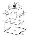
本発明の一実施形態によるシングルリールデータ記憶テープカートリッジは、一般には図1の20で示される。一般的に、シングルリールデータ記憶テープカートリッジ20は、ハウジング22、ブレーキアセンブリ24、シングルテープリールアセンブリ26、記憶テープ28、リーダーブロック30、および内部テープガイド32を含む。シングルテープリールアセンブリ26は、ハウジング22内に設けられる。記憶テープ28は、次にシングルテープリールアセンブリ26に巻き取られ、かつリーダーブロック30に取り付けられる先端部29を含む。 A single reel data storage tape cartridge according to one embodiment of the present invention is shown generally at 20 in FIG. Generally, a single reel data storage tape cartridge 20 includes a
ハウジング22は、典型的なテープ駆動機構(図示せず)によって受け入れられるような大きさにされている。したがって、ハウジング22は、他の寸法も等しく受入れ可能ではあるが、約125mm×110mm×21mmの大きさを示している。このことを念頭に置いて、ハウジング22は、第1ハウジング部34および第2ハウジング部36によって画定される。一実施形態では、第1ハウジング部34はカバーを構成し、一方第2ハウジング部36はベースを構成する。明細書全体にわたって用いられるように、方向用語、たとえば「カバー」、「ベース」、「上部」、「下部」、「頂部」、「底部」等は、あくまでも図示するために用いられるものであり、決して限定するものではない。
第1ハウジング部34及び第2ハウジング部36は、好ましくは傾斜を付けられておりかつテープアクセスウィンドウ40を形成する一コーナー38を除いて、それぞれ、相互に合わさるような大きさにされておりかつ一般に矩形である。テープアクセスウィンドウ40は、リーダーブロック30がテープアクセスウィンドウ40から除去されるとき記憶テープ28をテープ駆動機構(図示せず)にねじ込むことができるように、記憶テープ28がハウジング22から出るための開口部にもなる。逆に、リーダーブロック30がテープアクセスウィンドウ40と係合されると、テープアクセスウィンドウ40が覆われる。 The
テープアクセスウィンドウ40に加えて、第2ハウジング部36は、さらに中央開口部42を形成する。中央開口部42は、テープ駆動機構(図示せず)のドライブチャック部分によって、シングルテープリールアセンブリ26へのアクセスを容易にしている。 In addition to the
ブレーキアセンブリ24は、先行技術において公知の型であり、かつ一般にブレーキ44およびばね46を含む。シングルテープリールアセンブリ26は、また公知の部品であり、かつ上部フランジ48、下部フランジ50、およびブレーキアセンブリ24を同軸で受け入れるような大きさにされた環形のハブ52を含む。記憶テープ28は、テープリールフランジ48および50によって横方向に拘束されて、ハブ52に巻き取られる。先行技術において公知であるように、ブレーキ44およびばね46は、シングルリールデータ記憶テープカートリッジ20が使用されていないとき、シングルテープリールアセンブリ26をハウジング22に選択的に「係止」する。代わりに、ブレーキアセンブリ24および/またはシングルテープリールアセンブリ26のための他の構成も、等しく受入れ可能である。 The
記憶テープ28は、好ましくは、先行技術で一般に公知の型の磁気テープである。たとえば、記憶テープ28は、一方側では適当なバインダーシステム内に分散される磁気材料の層で被覆され、かつ他方側では適当なバインダーシステム内に分散される導電材料で被覆される均合のとれたポリエチレンナフタレート(PEN)系材料から成ってもよい。受入れ可能な磁気テープは、たとえばミネソタ州オークディールのイメーション株式会社(Imation Corp.(Oakadale, MN))から入手可能である。
リーダーブロック30は、テープアクセスウィンドウ40を覆い、かつ記憶テープ28の検索を容易にする。大まかに言うと、リーダーブロック30は、ハウジング22のウィンドウ40に合致し、かつ記憶テープ28を読取/書込ヘッドに送り込む際にテープ駆動機構(図示せず)が操作すべき把握面となることによってそのテープ駆動機構と協動するような形状にされている。この点に関しては、リーダーブロック30は、好ましくは剛性材料から形成される。一実施形態では、リーダーブロックは、他の材料および製造技術も受入れ可能であるが、ガラス繊維入りポリカーボネートから成形されている。さらに、リーダーブロック30の代わりに、ダンベル形のピン等の他の公知の部品を使用することもできる。 The
好ましい実施形態では、図2に示されるように、テープアクセスウィンドウ40に対向して、テープガイド32は成形されて第2ハウジング部36となる。この点に関しては、ハウジング22は、前壁54および後壁56を画定する。テープアクセスウィンドウ40の少なくとも一部分は、前壁54に形成される。テープガイド32は、シングルテープリールアセンブリ26と後壁56との間に位置決めされる。説明を容易にするために、記憶テープ28は図2には示さない。テープガイド32は、弓状背面60、弓状接触面62、頂部フランジ64、および底部フランジ66を含む。弓状背面60は、シングルテープリールアセンブリ26のフランジ、たとえば上部フランジ48に合致するように湾曲している。テープ接触部62もまた湾曲されている。頂部フランジ64および底部フランジ66は、それぞれ、テープ接触面62を越えて突出し、かつ記憶テープ28(図1)がテープガイド32を越えて移動するにつれて、その記憶テープ28の横移動(横運動)を制限する。このようにして、テープ接触面62は、移動しているデータ記憶テープ28のための通路の一部分を形成する。特に、テープガイド32は、シングルテープリールアセンブリ26からテープアクセスウィンドウ40までの記憶テープ28の通路を、テープガイド32とテープアクセスウィンドウ40との間の通路が、ハブ52が何回も巻き付けられた記憶テープ28を保持しようとほんの数回しか巻き付けられていない記憶テープ28を保持しようと一定であるように画定する。 In a preferred embodiment, the
好ましい一実施形態では、頂部フランジ64および底部フランジ66は、それぞれ、記憶テープ28の横移動を、300μm未満、好ましくは100μm未満に制限する。より好ましくは、記憶テープ28の横運動は、50μm未満に制限される。たとえば、例証的な一実施形態では、頂部フランジ64および底部フランジ66は、記憶テープ28の横運動を、約20μmに制限する。 In one preferred embodiment,
好ましい一実施形態では、記憶テープ28(図1)の通路は、記憶テープ28を、ハブ52から離れて、テープガイド32までかつテープ接触面62に沿って、最終的にはテープアクセスウィンドウ40から外へ案内することによって維持される。たとえば、記憶テープ28は、シングルテープリールアセンブリ26からテープガイド32の第一端部67までの通路を移動する。記憶テープ28は、テープ接触面62を通過して、テープガイド32の第2端部68に到達する。第2端部68は、記憶テープ28の通路をテープアクセスウィンドウ40に整列させるように構成される。したがって、記憶テープ28がテープガイド32を出るにつれて、その通路は、テープガイド32からテープアクセスウィンドウ40までの記録テープ28の一定の通路が維持されるように、テープアクセスウィンドウ40と常に整列される。その結果、記憶テープ28の通路は、それがテープアクセスウィンドウ40を越えて延びないように維持される。記憶テープ28の横移動は、図3によりよく示されるように、頂部フランジ64および底部フランジ66によって最小にされ、記憶テープ28をテープガイド32に沿って案内するのを容易にする。 In one preferred embodiment, the passage of the storage tape 28 (FIG. 1) moves the
図3は、図2のテープガイド32の断面を示しており、記憶テープ28の断面を説明を明確にするために付け加えている。描かれているように、記憶テープ28の横移動は、頂部フランジ64および底部フランジ66によってそれぞれ制限されている。頂部フランジ64および底部フランジ66は、記憶テープ28がテープ接触面62を横切るにつれて、記憶テープ28の移動を制限するように構成される。特に、頂部フランジ64および底部フランジ66は、横方向に移動することができる記憶テープ28の対向端縁69に対する剛性の止めの役目を果たす。その結果、テープ接触面62は、記憶テープ28のための通路を画定し、かつ頂部フランジ64および底部フランジ66は、記憶テープ28の端縁69の横移動を制限する。 FIG. 3 shows a cross section of the
典型的な一実施形態では、テープガイド32は、好ましくは、耐久性材料、たとえば金属、セラミック、またはプラスチックから製造される。テープガイド32を製造する適当な材料の例としては、アルミニウム、鋼、ステンレス鋼、ポリエステル、ナイロン、および、一般に、熱可塑性および熱硬化性プラスチックが挙げられる。テープガイド32を含む耐久性材料を、好ましくは、その接触面で耐摩耗性となるように被覆する。一つの好ましいコーティングとしては、少なくともC20のロックウェル硬度まで熱処理される無電解金属コーティングがある。 In one exemplary embodiment,
図2は、ハウジング22によって一体的に形成されたテープガイド32の好ましい一実施形態を示しているが、代わりの好ましい実施形態では、図4に示されるように、挿入可能なテープガイド70は、別個に形成されかつハウジング71に挿入される。図4は、図2のハウジング22内の部品の位置決めに非常に類似の態様でハウジング71内に設けられる種々の内部部品を示している。特に、シングルテープリールアセンブリ26は、ハウジング71内に設けられ、かつテープアクセスウィンドウ40に対向してハウジング71に挿入されるテープガイド70と協動する。テープガイド70は、弓状背面72および弓状テープ接触面74を含む。背面72は、シングルテープリールアセンブリ26の上部フランジ48の円形を補足するように湾曲されている。テープ接触面74は、記憶テープ28(図1)を案内しかつテープアクセスウィンドウ40の方向に記憶テープ28のための通路を画定するように構成されている。記憶テープ28の案内を促進するために、テープガイド70は、頂部フランジ76および底部フランジ78を含み、それらは、図3のテープガイド32の断面についても同様に説明したが、記憶テープ28の横移動を制限している。挿入可能なテープガイド70には、第1ねじボス82の周囲で結合するように構成された第1係合端部80および第2ねじボス86の周囲で結合するように構成された第2係合端部84が設けられている。この点に関しては、第1係合端部80は第1コーナーガイド88を形成し、かつ第2係合端部84は第2コーナーガイド90を形成する。したがって、一体形のコーナーガイド88および90を形成する際に、テープガイド70は、二つのねじボス82および86の回りに固定される。特に、図4に示されるように、本発明の一実施形態に従って、テープガイド70は、シングルテープリールアセンブリ26からテープアクセスウィンドウ40までの記憶テープ28の通路を画定する。具体的には、図5によりよく示されるように、テープガイド70は、テープアクセスウィンドウ40へ入りかつそこから出るときの記憶テープ28のための一定通路92を画定する。 While FIG. 2 shows one preferred embodiment of the
テープアクセスウィンドウ40へ入りかつそこから出るときの記憶テープ28の一定通路92によって、記憶テープ28をテープ駆動機構(図示せず)と常に係合することができ、かつ記憶テープ28の横移動に起因する読取/書込エラーを最小にする。図5に示されるように、記憶テープ28の通路は、点線として表される。記憶テープ28は、ハブ52が記憶テープ28でふさがれていようと(いっぱいのテープ通路94)、ハブ52に記憶テープ28がほとんどなかろうと(空のテープ通路96)維持されるテープアクセスウィンドウ40を介して一定の通路92を移動する。この点に関しては、テープガイド70は、テープアクセスウィンドウ40を介する記憶テープ28の一定の通路92を画定する。 The
テープガイド70を、ハウジング71(図4)の製造に続いてハウジング71に挿入することができるか、あるいはテープアクセスウィンドウ40に対向して、テープガイド32を成形して直接ハウジング22(図2)にすることができる。いずれの場合にも、テープガイド32またはテープガイド70は、シングルテープリールアセンブリ26からテープアクセスウィンドウ40までの記憶テープ28(図1)の通路(たとえば92および96)を画定する。それでも、一つ以上の補助ガイドをデータ記憶テープカートリッジハウジング内にさらに位置決めして、記憶テープ28をテープガイド70へおよび/またはテープガイド70から案内しかつテープ通路の長さを増す方が有利でありうる。たとえば、図6は、テープガイド70および補助ガイド100が設けられた代わりの実施形態のシングルリールテープカートリッジ98の一部分の分解図を示している。図6の一実施形態では、補助ガイド100は、補助ガイド100の他の形状および/または位置もまた受入れ可能であるが、コーナーガイドにもなる。テープガイド70および補助ガイド100の、シングルテープリールアセンブリ26に対する正確な整列を容易にするために、ベースプレート102が利用される。ハブピン104は、シングルテープリールアセンブリ26をベースプレート102に取り付ける。テープガイド70および補助ガイド100は、先行技術におけるいかなる公知の機械的手段によっても、ベースプレート102に装着される。ベースプレート102をハウジング98内に配設する一つの利点は、シングルテープリールアセンブリ26、よって記憶テープ28を、公知の距離すなわち基準だけ、ベースプレート102の水平面の上方に正確に配置することができるということである。テープ駆動機構(図示せず)は、それ自体、記憶テープ28を位置決めする公知のデータ、より重要なことには記憶テープ28に埋め込まれたデータトラックを参照することができる。したがって、ベースプレート102は、その表面上に設けられる部品のための取り付け手段とテープガイド70および補助ガイド100をシングルテープリールアセンブリ26に対して位置決めする参照手段とのどちらにもなる。
補助ガイド100は、ハウジング98の内周に沿って記憶テープ28(図1)を方向付け、かつ記憶テープ28をテープ接触面74と接触する前に整列させるのに役立つ。補助ガイド100は、それ自体、記憶テープ28を、その通路内をテープガイド70まで案内する。補助ガイド100は、また頂部フランジ110および底部フランジ112を含んでもよく、それらは記憶テープ28の横運動を制限する。任意で、テープガイド70をハウジング98内に配設し、かつ補助ガイド100なしにベースプレート102に取り付けることができるだろう。しかしながら、図6に示されるように、補助ガイド100は、ベースプレート102のコーナー114に位置決めされ、かつハウジング98に嵌合するような大きさにされている。補助ガイド100は、様々な形状および配置を取ることができ、かつ二つ以上の補助ガイドを含むこともある。たとえば、図6は、補助ガイド100に対向して位置決めされる第2補助ガイド116を描いている。第2補助ガイド116はピンであり、それは頂部および/または底部フランジを含んでも含まなくてもよく、かつヘッドアクセスウィンドウ40に隣接する追加案内となる。 The
ベースプレート102の利用は、カートリッジ内案内と両立する。たとえば、テープガイド70を、その垂直位置が、円滑な巻取および巻出のために、ひいては記憶テープ28(図1)のテープ駆動機構(図示せず)に対する改良された整列のために、シングルテープリールアセンブリ26と整列されるようにベースプレート102に装着することができる。さらに、ベースプレート102を型枠として使用して、ハウジング98内に他の特性を含めることができる。ベースプレート102に追加することができるであろう他の部品は、パックアーム、イン・カートリッジメモリチップ、遊びロール、およびラップピンである。最後に、シングルテープリールアセンブリ26のハブ52は、ボールおよびスリーブ等のジャーナル軸受を、その中の中央ボアに組み込むことができる。したがって、シングルテープリールアセンブリ26は、揺れを少なくして回転し、それゆえ初期横テープ運動をほとんど示さない。ベースプレート102をハウジング98内で使用するもう一つのメリットは、ベースプレート102によって、設計に剛性が増し、その結果落下試験性能が改良されるということである。 The use of the
データ記憶テープを含む磁気メディアは、一般に研磨性がある。データ記憶テープ28(図1)がテープ接触面74および補助ガイド100に沿って移動するにつれて、データ記憶テープ28は部品と接触し、表面を研磨しうる。したがって、テープ接触面74および補助ガイド100を、研磨性記憶テープ28メディアによって与えられる磨耗から保護すべきである。したがって、テープ接触面74および補助ガイド100は、好ましくは、金属、セラミック、またはプラスチック等の耐久性材料から製造される。テープガイド70および補助ガイド100を製造する適当な材料の例として、アルミニウム、鋼、ステンレス鋼、ポリエステル、ナイロン、および、一般に、熱可塑性および熱硬化性プラスチックが挙げられる。テープガイド70および補助ガイド100を含む耐久性材料を、好ましくは、それらの接触面で耐磨耗性となるように被覆する。一つの好ましいコーティングは、少なくともC20のロックウェル硬度まで熱処理される無電解金属コーティングである。 Magnetic media, including data storage tapes, are generally abrasive. As the data storage tape 28 (FIG. 1) moves along the
20 シングルリールデータ記憶テープカートリッジ
22、98 ハウジング
24 ブレーキアセンブリ
26 シングルテープリールアセンブリ
28 記憶テープ
29 先端部
30 リーダブロック
32、70 テープガイド
34、36 ハウジング部
38、114 コーナー
40 テープアクセスウィンドウ
42 中央開口部
44 ブレーキ
46 ばね
48 上部フランジ
50 下部フランジ
52 ハブ
54 前壁
56 後壁
60、72 背面
62、74 テープ接触面
64、76、110 頂部フランジ
66、78、112 底部フランジ
67、68 端部
71 ハウジング
80、84 係合端部
82、86 ねじボス
88、90 コーナーガイド
92、94、96 テープ通路
100、116 補助ガイド
102 ベースプレート
104 ハブピン
20 Single Reel Data
Claims (6)
Translated fromJapaneseハウジング内に回転可能に設けられ、ハブを含むシングルテープリールアセンブリと、
ハブに巻き付けられる記憶テープと、
前記シングルテープリールアセンブリに隣接する前記ハウジング内に設けられかつ前記テープアクセスウィンドウに対向して設けられるテープガイドと、を備えるシングルリールデータ記憶テープカートリッジであって、
前記テープガイドは、前記シングルテープリールアセンブリから前記テープアクセスウィンドウまでの前記記憶テープの通路を画定する、シングルリールデータ記憶テープカートリッジ。A housing defining a tape access window;
A single tape reel assembly rotatably provided in the housing and including a hub,
A storage tape wrapped around the hub,
A tape guide provided in the housing adjacent to the single tape reel assembly and opposed to the tape access window.
A single reel data storage tape cartridge, wherein the tape guide defines a path for the storage tape from the single tape reel assembly to the tape access window.
前記頂部フランジおよび底部フランジは、前記記憶テープの横運動を300μm未満に制限するように構成される、請求項1に記載のカートリッジ。The tape guide includes a top flange and a bottom flange, both of which limit the lateral movement of the storage tape;
The cartridge of claim 1, wherein the top flange and the bottom flange are configured to limit lateral movement of the storage tape to less than 300 μm.
前記シングルリールデータ記憶テープカートリッジを前記テープ駆動機構と係合させるステップであって、前記シングルリールデータ記憶テープカートリッジは、テープアクセスウィンドウを有するハウジング、前記ハウジング内に回転可能に設けられるシングルテープリールアセンブリ、および前記テープリールアセンブリに巻き取られる記憶テープを備えた、ステップと、
前記テープアクセスウィンドウに対向して前記ハウジング内に設けられるテープガイドによって少なくとも部分的に画定されるテープ通路に沿って前記記憶テープを係合させるステップと、
前記テープアクセスウィンドウを通して前記記憶テープを駆動しかつ前記記憶テープを前記読取/書込ヘッドに係合させるステップとを含み、
前記テープガイドは、前記テープリールアセンブリから前記テープアクセスウィンドウまでの前記記憶テープの通路を画定する、方法。A method of using a tape drive including a single reel data storage tape cartridge and a read / write head, comprising:
Engaging the single reel data storage tape cartridge with the tape drive mechanism, wherein the single reel data storage tape cartridge includes a housing having a tape access window, and a single tape reel assembly rotatably provided within the housing. And a storage tape wound on the tape reel assembly.
Engaging the storage tape along a tape path at least partially defined by a tape guide provided in the housing opposite the tape access window;
Driving the storage tape through the tape access window and engaging the storage tape with the read / write head;
The method, wherein the tape guide defines a path for the storage tape from the tape reel assembly to the tape access window.
5. The method of claim 4, wherein engaging the storage tape along a tape path defined at least in part by a tape guide includes limiting lateral movement of the storage tape to less than about 300 microns. .
Applications Claiming Priority (1)
| Application Number | Priority Date | Filing Date | Title |
|---|---|---|---|
| US10/452,332US6915982B2 (en) | 2003-06-02 | 2003-06-02 | Single reel data storage tape cartridge with internal tape guide |
Publications (1)
| Publication Number | Publication Date |
|---|---|
| JP2004362755Atrue JP2004362755A (en) | 2004-12-24 |
Family
ID=33451971
Family Applications (1)
| Application Number | Title | Priority Date | Filing Date |
|---|---|---|---|
| JP2004161385APendingJP2004362755A (en) | 2003-06-02 | 2004-05-31 | Single reel data storage tape cartridge with internal tape guide |
Country Status (2)
| Country | Link |
|---|---|
| US (1) | US6915982B2 (en) |
| JP (1) | JP2004362755A (en) |
Cited By (2)
| Publication number | Priority date | Publication date | Assignee | Title |
|---|---|---|---|---|
| US7407125B2 (en) | 2005-10-11 | 2008-08-05 | Fujifilm Corporation | Recording tape cartridge and driving device |
| US7540444B2 (en) | 2005-02-22 | 2009-06-02 | Fujifilm Corporation | Recording tape cartridge |
Families Citing this family (4)
| Publication number | Priority date | Publication date | Assignee | Title |
|---|---|---|---|---|
| US7446972B2 (en)* | 2003-07-24 | 2008-11-04 | Quantum Corporation | Tape drive with a single reel tape cartridge having single guide surface and method for driving |
| JP4663358B2 (en)* | 2004-12-01 | 2011-04-06 | 富士フイルム株式会社 | Recording tape cartridge |
| US20070025012A1 (en)* | 2005-07-18 | 2007-02-01 | Quantum Corporation | Tape drive having improved tape path and associated methods |
| JP2013140657A (en)* | 2012-01-05 | 2013-07-18 | Fujitsu Ltd | Cartridge tape and drive device thereof |
Family Cites Families (16)
| Publication number | Priority date | Publication date | Assignee | Title |
|---|---|---|---|---|
| US956178A (en)* | 1908-03-16 | 1910-04-26 | Arthur E Bailey | Magazine for picture-films. |
| US959601A (en)* | 1910-01-24 | 1910-05-31 | Nicholas Power | Fireproof magazine for film-reels. |
| GB1406084A (en)* | 1971-09-17 | 1975-09-10 | Sony Corp | Cartridge for use in magnetic recording and or reproducing apparatus |
| US3804498A (en)* | 1973-02-28 | 1974-04-16 | Ragen Precision Ind Inc | Cassette for film |
| JPH0222638A (en)* | 1988-07-11 | 1990-01-25 | Brother Ind Ltd | Image forming device |
| WO1995032503A1 (en) | 1994-05-19 | 1995-11-30 | Minnesota Mining And Manufacturing Company | Tape guides for data cartridges |
| JP3203980B2 (en)* | 1994-10-07 | 2001-09-04 | ノーリツ鋼機株式会社 | Photo printing equipment |
| US5906324A (en) | 1998-05-04 | 1999-05-25 | International Business Machines Corporation | Single reel tape cartridge with integral tape guide |
| US5969913A (en)* | 1998-06-11 | 1999-10-19 | Dimation Corp | Data storage tape cartridge with misinsertion notch |
| US6069777A (en)* | 1998-06-11 | 2000-05-30 | Imation Corp. | Data storage tape cartridge with exposed base plate datum for tape registration |
| JP2000182352A (en)* | 1998-12-11 | 2000-06-30 | Sony Corp | Tape cassette |
| US6246542B1 (en)* | 1999-08-02 | 2001-06-12 | International Business Machines Corporation | Single magnetic tape reel with dual-sided recording capability |
| US6633454B1 (en)* | 1999-09-27 | 2003-10-14 | Imation Corp. | Shock detection for a data storage device |
| US6249401B1 (en)* | 1999-11-04 | 2001-06-19 | Imation Corp. | Belt-driven data cartridge with yoke mechanism |
| US6405957B1 (en) | 2000-02-15 | 2002-06-18 | Imation Corp. | Data storage tape cartridge and tape path with an idler wrap guide for reduced lateral tape movement |
| US6343757B1 (en)* | 2000-03-30 | 2002-02-05 | Imation Corp. | Elongated clearance-type guide for magnetic tape |
- 2003
- 2003-06-02USUS10/452,332patent/US6915982B2/ennot_activeExpired - Fee Related
- 2004
- 2004-05-31JPJP2004161385Apatent/JP2004362755A/enactivePending
Cited By (2)
| Publication number | Priority date | Publication date | Assignee | Title |
|---|---|---|---|---|
| US7540444B2 (en) | 2005-02-22 | 2009-06-02 | Fujifilm Corporation | Recording tape cartridge |
| US7407125B2 (en) | 2005-10-11 | 2008-08-05 | Fujifilm Corporation | Recording tape cartridge and driving device |
Also Published As
| Publication number | Publication date |
|---|---|
| US20040238670A1 (en) | 2004-12-02 |
| US6915982B2 (en) | 2005-07-12 |
Similar Documents
| Publication | Publication Date | Title |
|---|---|---|
| JP4875017B2 (en) | Recording tape cartridge | |
| US7440231B2 (en) | Single reel tape cartridge having guide surface | |
| US5893526A (en) | Tape guides for data cartridges | |
| US6405957B1 (en) | Data storage tape cartridge and tape path with an idler wrap guide for reduced lateral tape movement | |
| EP1746592A2 (en) | Tape drive having improved tape path and associated methods | |
| US6078481A (en) | Tape storage cartridge having two-level tape path | |
| JP2004362755A (en) | Single reel data storage tape cartridge with internal tape guide | |
| US6343757B1 (en) | Elongated clearance-type guide for magnetic tape | |
| US6644581B2 (en) | Flange guide for improved tape winding | |
| JP4311880B2 (en) | Data storage tape cartridge having an exposed base plate reference point for tape alignment | |
| US5490029A (en) | Compliant tape guide for data cartridges | |
| US6568617B1 (en) | Leader with smoothing indenture | |
| US5409174A (en) | High speed transport cassette | |
| US5433397A (en) | High speed tape transport system | |
| US6915976B2 (en) | Recording tape cartridge and drive device thereof | |
| US6457664B1 (en) | Hybrid belt-driven data storage tape cartridge | |
| US7540444B2 (en) | Recording tape cartridge | |
| JP3443339B2 (en) | Tape guide mechanism of tape recorder | |
| US6874720B2 (en) | Data storage tape cartridge with subambient pressure feature | |
| JP2004022049A (en) | Magnetic tape cartridge | |
| US6854680B2 (en) | Recording tape cartridge | |
| US20040238671A1 (en) | Magnetic tape guide and method of use | |
| EP1391891A2 (en) | Tape cartridge with multiple keying features | |
| US7331541B2 (en) | Recording tape cartridge | |
| CN1949384B (en) | Recording tape cartridge |