JP2004358248A - Device and method for assisting pulmonary decompression - Google Patents
Device and method for assisting pulmonary decompressionDownload PDFInfo
- Publication number
- JP2004358248A JP2004358248AJP2004159778AJP2004159778AJP2004358248AJP 2004358248 AJP2004358248 AJP 2004358248AJP 2004159778 AJP2004159778 AJP 2004159778AJP 2004159778 AJP2004159778 AJP 2004159778AJP 2004358248 AJP2004358248 AJP 2004358248A
- Authority
- JP
- Japan
- Prior art keywords
- lung
- lungs
- air
- oxygen
- patient
- Prior art date
- Legal status (The legal status is an assumption and is not a legal conclusion. Google has not performed a legal analysis and makes no representation as to the accuracy of the status listed.)
- Pending
Links
- 230000006837decompressionEffects0.000titleclaimsabstractdescription36
- 238000000034methodMethods0.000titleclaimsdescription58
- 230000002685pulmonary effectEffects0.000titleabstractdescription17
- 210000004072lungAnatomy0.000claimsabstractdescription251
- 239000012530fluidSubstances0.000claimsabstractdescription18
- 238000007789sealingMethods0.000claimsabstractdescription14
- 238000004891communicationMethods0.000claimsabstractdescription10
- 206010014561EmphysemaDiseases0.000abstractdescription43
- 238000002640oxygen therapyMethods0.000abstractdescription36
- 208000006545Chronic Obstructive Pulmonary DiseaseDiseases0.000abstractdescription21
- 230000007774longtermEffects0.000abstractdescription18
- 206010006451bronchitisDiseases0.000abstractdescription14
- 206010006458Bronchitis chronicDiseases0.000abstractdescription11
- 208000007451chronic bronchitisDiseases0.000abstractdescription11
- 206010021143HypoxiaDiseases0.000abstractdescription7
- 230000007954hypoxiaEffects0.000abstractdescription6
- 238000013022ventingMethods0.000abstract1
- 239000003570airSubstances0.000description118
- QVGXLLKOCUKJST-UHFFFAOYSA-Natomic oxygenChemical compound[O]QVGXLLKOCUKJST-UHFFFAOYSA-N0.000description89
- 239000001301oxygenSubstances0.000description89
- 229910052760oxygenInorganic materials0.000description89
- 238000009423ventilationMethods0.000description63
- 239000000126substanceSubstances0.000description40
- 210000001519tissueAnatomy0.000description39
- 238000009472formulationMethods0.000description25
- 239000000203mixtureSubstances0.000description25
- 210000004224pleuraAnatomy0.000description23
- 210000003437tracheaAnatomy0.000description23
- 229940079593drugDrugs0.000description22
- 239000003814drugSubstances0.000description22
- 210000000621bronchiAnatomy0.000description21
- 210000000779thoracic wallAnatomy0.000description16
- 210000000115thoracic cavityAnatomy0.000description15
- 210000003491skinAnatomy0.000description14
- 239000000463materialSubstances0.000description13
- 210000003281pleural cavityAnatomy0.000description13
- 230000029058respiratory gaseous exchangeEffects0.000description13
- 238000010586diagramMethods0.000description12
- 210000003097mucusAnatomy0.000description12
- 230000006378damageEffects0.000description11
- 239000000853adhesiveSubstances0.000description9
- 230000001070adhesive effectEffects0.000description9
- 239000003795chemical substances by applicationSubstances0.000description9
- 230000006835compressionEffects0.000description9
- 238000007906compressionMethods0.000description9
- 210000003800pharynxAnatomy0.000description8
- 201000010099diseaseDiseases0.000description7
- 208000037265diseases, disorders, signs and symptomsDiseases0.000description7
- 230000006870functionEffects0.000description7
- 239000010410layerSubstances0.000description7
- 230000002035prolonged effectEffects0.000description7
- 230000005855radiationEffects0.000description6
- 238000001959radiotherapyMethods0.000description6
- 210000003123bronchioleAnatomy0.000description5
- 210000000038chestAnatomy0.000description5
- 238000012377drug deliveryMethods0.000description5
- 239000007789gasSubstances0.000description5
- 238000012423maintenanceMethods0.000description5
- 210000001331noseAnatomy0.000description5
- 230000001936parietal effectEffects0.000description5
- 239000000454talcSubstances0.000description5
- 229940033134talcDrugs0.000description5
- 229910052623talcInorganic materials0.000description5
- SGKRLCUYIXIAHR-AKNGSSGZSA-N(4s,4ar,5s,5ar,6r,12ar)-4-(dimethylamino)-1,5,10,11,12a-pentahydroxy-6-methyl-3,12-dioxo-4a,5,5a,6-tetrahydro-4h-tetracene-2-carboxamideChemical compoundC1=CC=C2[C@H](C)[C@@H]([C@H](O)[C@@H]3[C@](C(O)=C(C(N)=O)C(=O)[C@H]3N(C)C)(O)C3=O)C3=C(O)C2=C1OSGKRLCUYIXIAHR-AKNGSSGZSA-N0.000description4
- 108010006654BleomycinProteins0.000description4
- CURLTUGMZLYLDI-UHFFFAOYSA-NCarbon dioxideChemical compoundO=C=OCURLTUGMZLYLDI-UHFFFAOYSA-N0.000description4
- 241000124008MammaliaSpecies0.000description4
- 230000008901benefitEffects0.000description4
- 229960001561bleomycinDrugs0.000description4
- OYVAGSVQBOHSSS-UAPAGMARSA-Obleomycin A2Chemical compoundN([C@H](C(=O)N[C@H](C)[C@@H](O)[C@H](C)C(=O)N[C@@H]([C@H](O)C)C(=O)NCCC=1SC=C(N=1)C=1SC=C(N=1)C(=O)NCCC[S+](C)C)[C@@H](O[C@H]1[C@H]([C@@H](O)[C@H](O)[C@H](CO)O1)O[C@@H]1[C@H]([C@@H](OC(N)=O)[C@H](O)[C@@H](CO)O1)O)C=1N=CNC=1)C(=O)C1=NC([C@H](CC(N)=O)NC[C@H](N)C(N)=O)=NC(N)=C1COYVAGSVQBOHSSS-UAPAGMARSA-O0.000description4
- 230000008878couplingEffects0.000description4
- 238000010168coupling processMethods0.000description4
- 238000005859coupling reactionMethods0.000description4
- 238000009792diffusion processMethods0.000description4
- 229960003722doxycyclineDrugs0.000description4
- PCHJSUWPFVWCPO-UHFFFAOYSA-NgoldChemical compound[Au]PCHJSUWPFVWCPO-UHFFFAOYSA-N0.000description4
- 239000010931goldSubstances0.000description4
- 229910052737goldInorganic materials0.000description4
- 210000000867larynxAnatomy0.000description4
- 238000002595magnetic resonance imagingMethods0.000description4
- 239000003550markerSubstances0.000description4
- 230000007246mechanismEffects0.000description4
- 210000004379membraneAnatomy0.000description4
- 239000012528membraneSubstances0.000description4
- 239000007769metal materialSubstances0.000description4
- 201000003144pneumothoraxDiseases0.000description4
- 230000002285radioactive effectEffects0.000description4
- 239000000565sealantSubstances0.000description4
- 239000007787solidSubstances0.000description4
- 238000001356surgical procedureMethods0.000description4
- 208000000884Airway ObstructionDiseases0.000description3
- 210000004712air sacAnatomy0.000description3
- 239000008280bloodSubstances0.000description3
- 210000004369bloodAnatomy0.000description3
- 229940124630bronchodilatorDrugs0.000description3
- 210000004027cellAnatomy0.000description3
- 230000001684chronic effectEffects0.000description3
- 238000004140cleaningMethods0.000description3
- 238000010276constructionMethods0.000description3
- 238000005520cutting processMethods0.000description3
- 230000007423decreaseEffects0.000description3
- 238000013461designMethods0.000description3
- 238000011038discontinuous diafiltration by volume reductionMethods0.000description3
- 230000000694effectsEffects0.000description3
- 238000003780insertionMethods0.000description3
- 230000037431insertionEffects0.000description3
- 210000003928nasal cavityAnatomy0.000description3
- HLXZNVUGXRDIFK-UHFFFAOYSA-Nnickel titaniumChemical compound[Ti].[Ti].[Ti].[Ti].[Ti].[Ti].[Ti].[Ti].[Ti].[Ti].[Ti].[Ni].[Ni].[Ni].[Ni].[Ni].[Ni].[Ni].[Ni].[Ni].[Ni].[Ni].[Ni].[Ni].[Ni]HLXZNVUGXRDIFK-UHFFFAOYSA-N0.000description3
- 229910001000nickel titaniumInorganic materials0.000description3
- 229920000642polymerPolymers0.000description3
- 230000000241respiratory effectEffects0.000description3
- 238000011272standard treatmentMethods0.000description3
- 238000003860storageMethods0.000description3
- 230000000472traumatic effectEffects0.000description3
- 238000011282treatmentMethods0.000description3
- 206010011224CoughDiseases0.000description2
- 208000032843HemorrhageDiseases0.000description2
- 208000019693Lung diseaseDiseases0.000description2
- 239000004098TetracyclineSubstances0.000description2
- 230000009471actionEffects0.000description2
- 239000012080ambient airSubstances0.000description2
- 230000003872anastomosisEffects0.000description2
- 230000004888barrier functionEffects0.000description2
- 239000000560biocompatible materialSubstances0.000description2
- 208000034158bleedingDiseases0.000description2
- 230000000740bleeding effectEffects0.000description2
- 239000000168bronchodilator agentSubstances0.000description2
- 229910002092carbon dioxideInorganic materials0.000description2
- 239000001569carbon dioxideSubstances0.000description2
- 239000011248coating agentSubstances0.000description2
- 238000000576coating methodMethods0.000description2
- 238000002591computed tomographyMethods0.000description2
- 239000000356contaminantSubstances0.000description2
- 238000003745diagnosisMethods0.000description2
- 230000000916dilatatory effectEffects0.000description2
- 238000002224dissectionMethods0.000description2
- 210000002919epithelial cellAnatomy0.000description2
- 238000002594fluoroscopyMethods0.000description2
- 230000001771impaired effectEffects0.000description2
- 239000002085irritantSubstances0.000description2
- 231100000021irritantToxicity0.000description2
- 238000002357laparoscopic surgeryMethods0.000description2
- 238000011866long-term treatmentMethods0.000description2
- 238000002600positron emission tomographyMethods0.000description2
- 230000008569processEffects0.000description2
- 210000002345respiratory systemAnatomy0.000description2
- 239000002356single layerSubstances0.000description2
- 239000000021stimulantSubstances0.000description2
- 230000000153supplemental effectEffects0.000description2
- 229960002180tetracyclineDrugs0.000description2
- 229930101283tetracyclineNatural products0.000description2
- 235000019364tetracyclineNutrition0.000description2
- 150000003522tetracyclinesChemical class0.000description2
- 238000002560therapeutic procedureMethods0.000description2
- 238000003325tomographyMethods0.000description2
- 238000012546transferMethods0.000description2
- 238000002054transplantationMethods0.000description2
- FFTVPQUHLQBXQZ-KVUCHLLUSA-N(4s,4as,5ar,12ar)-4,7-bis(dimethylamino)-1,10,11,12a-tetrahydroxy-3,12-dioxo-4a,5,5a,6-tetrahydro-4h-tetracene-2-carboxamideChemical compoundC1C2=C(N(C)C)C=CC(O)=C2C(O)=C2[C@@H]1C[C@H]1[C@H](N(C)C)C(=O)C(C(N)=O)=C(O)[C@@]1(O)C2=OFFTVPQUHLQBXQZ-KVUCHLLUSA-N0.000description1
- 208000035143Bacterial infectionDiseases0.000description1
- MYMOFIZGZYHOMD-UHFFFAOYSA-NDioxygenChemical compoundO=OMYMOFIZGZYHOMD-UHFFFAOYSA-N0.000description1
- 102000004190EnzymesHuman genes0.000description1
- 108090000790EnzymesProteins0.000description1
- 241000282412HomoSpecies0.000description1
- 206010061218InflammationDiseases0.000description1
- 206010061297Mucosal erosionDiseases0.000description1
- 208000031481Pathologic ConstrictionDiseases0.000description1
- 208000003251PruritusDiseases0.000description1
- 208000036142Viral infectionDiseases0.000description1
- 238000002679ablationMethods0.000description1
- 230000001154acute effectEffects0.000description1
- 210000003484anatomyAnatomy0.000description1
- 208000008784apneaDiseases0.000description1
- 230000037147athletic performanceEffects0.000description1
- 208000022362bacterial infectious diseaseDiseases0.000description1
- 230000009286beneficial effectEffects0.000description1
- 229920000249biocompatible polymerPolymers0.000description1
- 230000017531blood circulationEffects0.000description1
- 210000004204blood vesselAnatomy0.000description1
- 230000036760body temperatureEffects0.000description1
- 210000002421cell wallAnatomy0.000description1
- 208000013116chronic coughDiseases0.000description1
- 230000003749cleanlinessEffects0.000description1
- 230000008602contractionEffects0.000description1
- 238000013270controlled releaseMethods0.000description1
- 230000001276controlling effectEffects0.000description1
- 230000007123defenseEffects0.000description1
- 230000007812deficiencyEffects0.000description1
- 238000007598dipping methodMethods0.000description1
- 230000009189divingEffects0.000description1
- 210000002615epidermisAnatomy0.000description1
- 210000002409epiglottisAnatomy0.000description1
- 210000003238esophagusAnatomy0.000description1
- 230000003090exacerbative effectEffects0.000description1
- 210000000416exudates and transudateAnatomy0.000description1
- 239000003292glueSubstances0.000description1
- 208000018875hypoxemiaDiseases0.000description1
- 239000007943implantSubstances0.000description1
- 238000002513implantationMethods0.000description1
- 238000010348incorporationMethods0.000description1
- 208000015181infectious diseaseDiseases0.000description1
- 230000002757inflammatory effectEffects0.000description1
- 230000004054inflammatory processEffects0.000description1
- 230000002427irreversible effectEffects0.000description1
- 230000007794irritationEffects0.000description1
- 230000007803itchingEffects0.000description1
- 239000007788liquidSubstances0.000description1
- 239000000314lubricantSubstances0.000description1
- 230000004199lung functionEffects0.000description1
- 239000011159matrix materialSubstances0.000description1
- 238000010297mechanical methods and processMethods0.000description1
- 230000005226mechanical processes and functionsEffects0.000description1
- HAWPXGHAZFHHAD-UHFFFAOYSA-NmechlorethamineChemical classClCCN(C)CCClHAWPXGHAZFHHAD-UHFFFAOYSA-N0.000description1
- 229960004961mechlorethamineDrugs0.000description1
- 238000002324minimally invasive surgeryMethods0.000description1
- 229960004023minocyclineDrugs0.000description1
- 238000002156mixingMethods0.000description1
- 238000012986modificationMethods0.000description1
- 230000004048modificationEffects0.000description1
- 230000009972noncorrosive effectEffects0.000description1
- 210000000056organAnatomy0.000description1
- 239000013618particulate matterSubstances0.000description1
- 230000001575pathological effectEffects0.000description1
- 230000000737periodic effectEffects0.000description1
- 230000002085persistent effectEffects0.000description1
- 238000002360preparation methodMethods0.000description1
- 210000003456pulmonary alveoliAnatomy0.000description1
- 238000011084recoveryMethods0.000description1
- 230000001105regulatory effectEffects0.000description1
- 238000004528spin coatingMethods0.000description1
- 238000005507sprayingMethods0.000description1
- 229910001220stainless steelInorganic materials0.000description1
- 239000010935stainless steelSubstances0.000description1
- 230000036262stenosisEffects0.000description1
- 208000037804stenosisDiseases0.000description1
- 230000002966stenotic effectEffects0.000description1
- 210000001562sternumAnatomy0.000description1
- 239000003894surgical glueSubstances0.000description1
- 230000009747swallowingEffects0.000description1
- 238000010408sweepingMethods0.000description1
- 210000001685thyroid glandAnatomy0.000description1
- 230000000699topical effectEffects0.000description1
- 239000012780transparent materialSubstances0.000description1
- 238000011277treatment modalityMethods0.000description1
- 230000003612virological effectEffects0.000description1
- 230000009278visceral effectEffects0.000description1
- 239000002699waste materialSubstances0.000description1
Images


Classifications
- A—HUMAN NECESSITIES
- A61—MEDICAL OR VETERINARY SCIENCE; HYGIENE
- A61M—DEVICES FOR INTRODUCING MEDIA INTO, OR ONTO, THE BODY; DEVICES FOR TRANSDUCING BODY MEDIA OR FOR TAKING MEDIA FROM THE BODY; DEVICES FOR PRODUCING OR ENDING SLEEP OR STUPOR
- A61M39/00—Tubes, tube connectors, tube couplings, valves, access sites or the like, specially adapted for medical use
- A61M39/02—Access sites
- A61M39/0247—Semi-permanent or permanent transcutaneous or percutaneous access sites to the inside of the body
- A—HUMAN NECESSITIES
- A61—MEDICAL OR VETERINARY SCIENCE; HYGIENE
- A61M—DEVICES FOR INTRODUCING MEDIA INTO, OR ONTO, THE BODY; DEVICES FOR TRANSDUCING BODY MEDIA OR FOR TAKING MEDIA FROM THE BODY; DEVICES FOR PRODUCING OR ENDING SLEEP OR STUPOR
- A61M16/00—Devices for influencing the respiratory system of patients by gas treatment, e.g. ventilators; Tracheal tubes
- A61M16/10—Preparation of respiratory gases or vapours
- A61M16/1005—Preparation of respiratory gases or vapours with O2 features or with parameter measurement
- A61M16/101—Preparation of respiratory gases or vapours with O2 features or with parameter measurement using an oxygen concentrator
- A—HUMAN NECESSITIES
- A61—MEDICAL OR VETERINARY SCIENCE; HYGIENE
- A61M—DEVICES FOR INTRODUCING MEDIA INTO, OR ONTO, THE BODY; DEVICES FOR TRANSDUCING BODY MEDIA OR FOR TAKING MEDIA FROM THE BODY; DEVICES FOR PRODUCING OR ENDING SLEEP OR STUPOR
- A61M16/00—Devices for influencing the respiratory system of patients by gas treatment, e.g. ventilators; Tracheal tubes
- A61M16/10—Preparation of respiratory gases or vapours
- A61M16/105—Filters
- A61M16/106—Filters in a path
- A—HUMAN NECESSITIES
- A61—MEDICAL OR VETERINARY SCIENCE; HYGIENE
- A61M—DEVICES FOR INTRODUCING MEDIA INTO, OR ONTO, THE BODY; DEVICES FOR TRANSDUCING BODY MEDIA OR FOR TAKING MEDIA FROM THE BODY; DEVICES FOR PRODUCING OR ENDING SLEEP OR STUPOR
- A61M39/00—Tubes, tube connectors, tube couplings, valves, access sites or the like, specially adapted for medical use
- A61M39/02—Access sites
- A61M39/0247—Semi-permanent or permanent transcutaneous or percutaneous access sites to the inside of the body
- A61M2039/0252—Semi-permanent or permanent transcutaneous or percutaneous access sites to the inside of the body for access to the lungs
- A—HUMAN NECESSITIES
- A61—MEDICAL OR VETERINARY SCIENCE; HYGIENE
- A61M—DEVICES FOR INTRODUCING MEDIA INTO, OR ONTO, THE BODY; DEVICES FOR TRANSDUCING BODY MEDIA OR FOR TAKING MEDIA FROM THE BODY; DEVICES FOR PRODUCING OR ENDING SLEEP OR STUPOR
- A61M39/00—Tubes, tube connectors, tube couplings, valves, access sites or the like, specially adapted for medical use
- A61M39/02—Access sites
- A61M39/0247—Semi-permanent or permanent transcutaneous or percutaneous access sites to the inside of the body
- A61M2039/0276—Semi-permanent or permanent transcutaneous or percutaneous access sites to the inside of the body for introducing or removing fluids into or out of the body
- A—HUMAN NECESSITIES
- A61—MEDICAL OR VETERINARY SCIENCE; HYGIENE
- A61M—DEVICES FOR INTRODUCING MEDIA INTO, OR ONTO, THE BODY; DEVICES FOR TRANSDUCING BODY MEDIA OR FOR TAKING MEDIA FROM THE BODY; DEVICES FOR PRODUCING OR ENDING SLEEP OR STUPOR
- A61M39/00—Tubes, tube connectors, tube couplings, valves, access sites or the like, specially adapted for medical use
- A61M39/02—Access sites
- A61M39/0247—Semi-permanent or permanent transcutaneous or percutaneous access sites to the inside of the body
- A61M2039/0297—Semi-permanent or permanent transcutaneous or percutaneous access sites to the inside of the body at least part of it being inflatable, e.g. for anchoring, sealing or removing
- A—HUMAN NECESSITIES
- A61—MEDICAL OR VETERINARY SCIENCE; HYGIENE
- A61M—DEVICES FOR INTRODUCING MEDIA INTO, OR ONTO, THE BODY; DEVICES FOR TRANSDUCING BODY MEDIA OR FOR TAKING MEDIA FROM THE BODY; DEVICES FOR PRODUCING OR ENDING SLEEP OR STUPOR
- A61M2202/00—Special media to be introduced, removed or treated
- A61M2202/02—Gases
- A61M2202/0208—Oxygen
- A—HUMAN NECESSITIES
- A61—MEDICAL OR VETERINARY SCIENCE; HYGIENE
- A61M—DEVICES FOR INTRODUCING MEDIA INTO, OR ONTO, THE BODY; DEVICES FOR TRANSDUCING BODY MEDIA OR FOR TAKING MEDIA FROM THE BODY; DEVICES FOR PRODUCING OR ENDING SLEEP OR STUPOR
- A61M2202/00—Special media to be introduced, removed or treated
- A61M2202/03—Gases in liquid phase, e.g. cryogenic liquids
Landscapes
- Health & Medical Sciences (AREA)
- Life Sciences & Earth Sciences (AREA)
- Heart & Thoracic Surgery (AREA)
- Anesthesiology (AREA)
- Engineering & Computer Science (AREA)
- Biomedical Technology (AREA)
- Pulmonology (AREA)
- Hematology (AREA)
- Animal Behavior & Ethology (AREA)
- General Health & Medical Sciences (AREA)
- Public Health (AREA)
- Veterinary Medicine (AREA)
- Emergency Medicine (AREA)
- Biophysics (AREA)
- Gastroenterology & Hepatology (AREA)
- External Artificial Organs (AREA)
Abstract
Description
Translated fromJapanese本発明は、気腫に侵された肺の中の取り込み空気を除去するシステム及び方法に関し、特に肺の外側胸膜層を通って格納/トラップ装置に通じる導管を介して非開存気道をバイパスすることにより気腫に侵された過膨張状態の肺の中の取り込み空気を除去するシステム及び方法に関する。本発明は又、取り込み空気を排出するために格納/トラップ装置ではなく気管を利用する副行(又は側副)換気バイパスシステムに関する。本発明は又、肺減圧術に役立つ器械及び方法に関する。本発明は又、化学的胸膜癒着システム及び方法に関する。 The present invention relates to a system and method for removing entrained air in an emphysema-affected lung, and in particular, bypasses a non-patent airway through a conduit through the outer pleural layer of the lung to a storage / trap device. The present invention relates to a system and method for removing trapped air in a hyperinflated lung, which is thereby affected by emphysema. The present invention is also directed to a collateral (or collateral) ventilation bypass system that utilizes the trachea rather than a storage / trap device to exhaust entrained air. The invention also relates to devices and methods useful for pulmonary decompression. The present invention also relates to chemical pleurodesis systems and methods.
なお、本願は、2003年5月29日に出願された米国仮特許出願第60/473,999号明細書の権益主張出願である。 This application is a claim of interest in US Provisional Patent Application No. 60 / 473,999 filed on May 29, 2003.
1930年代に遡る研究、特に1960年代及び1970年代初頭に行われた研究の結果として、長時間連続酸素療法が慢性閉塞性肺疾患のある低酸素血症患者の治療において有益であることが判明した。換言すると、コンスタントな追加酸素供給源を患者の肺に与えることにより患者の寿命及び生活の質を向上させることができる。 Studies dating back to the 1930s, particularly those performed in the 1960s and early 1970s, have shown that long-term continuous oxygen therapy is beneficial in treating hypoxemia patients with chronic obstructive pulmonary disease . In other words, providing a constant additional source of oxygen to the patient's lungs can improve the patient's life and quality of life.
しかしながら、医療費を抑えようという願望がありながら、慢性肺疾患のための連続酸素療法を行なった場合の追加の費用により酸素療法の年間費用が過度に増大するのではないかという懸念が増している。かくして、酸素療法は、もし行われる場合でもできるだけ費用効果が良いことが望ましい。 However, with the desire to reduce medical costs, there has been growing concern that the additional costs of continuous oxygen therapy for chronic lung disease may add excessively to the annual cost of oxygen therapy. I have. Thus, it is desirable that oxygen therapy be as cost effective as possible, if at all.
追加酸素を必要とする患者にとっての標準的な治療は、依然として鼻カニューレにより酸素源から酸素を投与することにある。しかしながら、かかる治療法では、無駄になり、しかも鼻に対する痛みや刺激を生じさせ、潜在的にそれを悪化させる場合のある多量の酸素が必要である。別の望ましくない結果も又報告されている。連続酸素療法の費用を軽減するのに役立つよう提案された種々の他の治療方法を検討した。 The standard treatment for patients in need of additional oxygen still consists in administering oxygen from an oxygen source via a nasal cannula. However, such therapies require large amounts of oxygen that can be wasted and cause nose pain and irritation, potentially exacerbating them. Another undesirable result has also been reported. A variety of other treatment modalities that have been proposed to help reduce the cost of continuous oxygen therapy were considered.
緊急輪状甲状膜切開術を実施したり気管切開管を提供して気道が閉塞状態にある患者が呼吸し続けることができるようにするための種々の器械及び方法が案出された。かかる装置は一般に、自発呼吸ができない患者に用いられることだけが意図されており、慢性肺疾患の長時間治療には適していない。典型的には、かかる装置は、皮膚を穿刺して比較的大径の湾曲した気管切開管が挿入される穴を気管の上方で喉頭の輪状膜に設けることにより取り付けられる。上述したように、かかる管を用いることは医療上、患者が気道の閉塞に起因して窒息する緊急事態に制限されている。かかる緊急気管切開管は、気道閉塞が取り除かれた後においては長時間治療に適していない。 Various instruments and methods have been devised for performing an emergency cricothyrotomy or providing a tracheostomy tube to allow a patient with an obstructed airway to continue breathing. Such devices are generally intended only for use in patients who cannot breathe spontaneously and are not suitable for long-term treatment of chronic lung disease. Typically, such devices are attached by puncturing the skin and providing a hole in the laryngeal cuff above the trachea where a relatively large diameter curved tracheostomy tube is inserted. As mentioned above, the use of such tubes is medically limited to emergency situations where the patient is suffocated due to airway obstruction. Such emergency tracheostomy tubes are not suitable for long-term treatment after the airway obstruction has been removed.
緊急時又は人工呼吸器用途に満足のゆくものであることが判明した他の器械が、ロジャーズに付与された米国特許第953,922号明細書、シェルデンに付与された米国特許第2,873,742号明細書、ブルメルカンプに付与された米国特許第3,384,087号明細書、トイに付与された米国特許第3,511,243号明細書、カルホウンに付与された米国特許第3,556,103号明細書、シェルデン等に付与された米国特許第2,991,787号明細書、ワイスに付与された米国特許第3,688,773号明細書、ワイス等に付与された米国特許第3,817,250号明細書及びポジに付与された米国特許第3,916,903号明細書に記載されている。 Other devices which have been found to be satisfactory for emergency or ventilator applications are U.S. Pat. No. 953,922 to Rogers and U.S. Pat. 742, U.S. Pat. No. 3,384,087 to Blumerkamp, U.S. Pat. No. 3,511,243 to Toys, U.S. Pat. No. 3,556 to Calhoun U.S. Pat. No. 2,991,787 to Shelden et al., U.S. Pat. No. 3,688,773 to Weiss, U.S. Pat. No. 3,817,250 and U.S. Pat. No. 3,916,903 to Positive.
気管切開管は、これらの意図した目的については満足のゆくものであるが、追加の酸素を慢性閉塞性肺疾患のある自発呼吸患者に投与するための手段として、外来患者により絶えず用いられるようには意図されていない。かかる気管切開管は一般に、全空気供給量を比較的短期間で患者に与えるよう設計されている。気管切開管は一般に、剛性又は半剛性構造のものであり、乳児では外径2.5mm乃至大人では外径15mmまでの範囲の口径のものである。これら気管切開管は通常、外科手技として又は緊急事態において、組織が血管性に乏しく且つ出血の恐れが低い輪状甲状膜を通って手術室に導入される。これら器械は、正常な呼吸が他の手段により回復されるまで空気の両方向の通過を可能にするようになっている。 Tracheostomy tubes, although satisfactory for these intended purposes, have been used constantly by outpatients as a means to administer additional oxygen to spontaneously breathing patients with chronic obstructive pulmonary disease. Is not intended. Such tracheostomy tubes are generally designed to provide a total air supply to the patient in a relatively short period of time. Tracheostomy tubes are generally of rigid or semi-rigid construction, with diameters ranging from 2.5 mm outside diameter for infants to 15 mm outside diameter for adults. These tracheostomy tubes are usually introduced into the operating room as a surgical procedure or in an emergency, through the cricothyroid membrane where the tissue is poorly vascularized and there is little risk of bleeding. These devices allow air to pass in both directions until normal breathing is restored by other means.
気管切開管の別のタイプは、ジェイコブズに付与された米国特許第3,682,166号明細書及び第3,788,326号明細書に開示されている。かかる米国特許明細書に記載されたカテーテルは、14又は16ゲージ針に被せられ、輪状甲状膜を通って刺入され、緊急時に空気又は酸素及び真空を供給して無呼吸の患者の呼吸を回復させるようになっている。空気又は酸素は、患者の肺が膨らんだり萎んだりすることができるよう30psi〜100psiで供給される。ジェイコブズのカテーテルは、従来用いられた他の気管切開管と同様、長期外来患者用途には適しておらず、かかる用途に合わせて容易には改造できない。 Another type of tracheostomy tube is disclosed in U.S. Pat. Nos. 3,682,166 and 3,788,326 to Jacobs. The catheter described in such U.S. Patent is overlaid with a 14 or 16 gauge needle, pierced through the cricoid thyroid, and supplies air or oxygen and vacuum in an emergency to restore the breathing of an apnea patient. It is made to let. Air or oxygen is provided at 30 psi to 100 psi to allow the patient's lungs to inflate and wither. Jacobs' catheters, like other tracheostomy tubes conventionally used, are not suitable for long-term outpatient use and cannot be easily modified for such use.
気管切開術用管の機能性が制限されているので、経気管カテーテルが提案され、長時間追加酸素療法に用いられた。例えば、ヘンリー・ジェイ・ハインリッヒ(Henry J. Heimlich )博士により開発された小径経気管カテーテル(16ゲージ)(『ジ・アナルズ・オブ・オトロジー・ライノロジー・アンド・ラリンゴロジー(THE ANNALS OF OTOLOGY, RHINOLOGY & LARYNGOLOGY)』,1982年11月〜12月に所収の論文「レスピラトリー・リハビリテーション・ウイズ・トランストリーキアル・オキシジェン・システム(Respiratory Rehabilitation with Transtracheal Oxygen System )」に記載されている)が、比較的大径の切断針(14ゲージ)を輪状甲状膜と胸骨陥凹との間の中点で気管中に挿入することにより用いられた。この大きさのカテーテルは、酸素を低圧、例えば2psiで毎分最高約3リットル供給することができるが、これは高流量を必要とする患者にとっては不十分な場合がある。しかしながら、これは、主としてカテーテルと酸素供給ホースとの間のコネクタが気管の前方部分に隣接してこれに当たっており、患者にとって容易に見たり容易に操作することができないという理由で、外来患者による使用及び保守、例えば定期的な取外し及びクリーニングには向いていない。さらに、このカテーテルは、外来患者を基準とした場合、その有効利用を阻害するキンク又は圧潰が生じないよう保護する積極的な手段を備えていない。かかる特徴は、望ましいだけでなく、長期外来患者及び家庭での介護用途に必要でもある。また、カテーテルからの酸素は、カテーテルの構造に鑑みて、即ちカテーテルが出口開口部を1つしか備えていないという理由で、気管を下って気管支相互間の分岐部に向かって真っ直ぐに差し向けられる。左気管支が右気管支よりも気管支に対し一層鋭角をなす気管支の正常な解剖学的構造に鑑みて、そのカテーテルからの酸素のうち大部分は、両方の気管支による均等な利用のために差し向けられ又は混合されないで、右気管支内へ差し向けられる傾向がある。また、生まれつきの構造のままでは酸素は胸峰に当たる場合があり、その結果望ましくないむずがゆさ及び咳が生じる。加うるに、かかる器械では、酸素の相当な部分が気管支の後壁に当てられると、この領域の粘膜のエロージョンが生じ、それによりあかぎれや出血が生じる場合がある。全体として、器械からの出力が制限されているので、器械は、患者が運動しているとき又は極めて活発である場合、或いは重度の疾患がある場合、十分な追加酸素を供給するようには作動しない。 Due to the limited functionality of tracheostomy tubes, transtracheal catheters have been proposed and used for prolonged supplemental oxygen therapy. For example, a small diameter transtracheal catheter (16 gauge) developed by Dr. Henry J. Heimlich ("The ANNALS OF OTOLOGY, RHINOLOGY & LARYNGOLOGY") ) ”, Published in November-December 1982, is described in“ Respiratory Rehabilitation with Transtracheal Oxygen System ”). A cutting needle (14 gauge) was used by inserting it into the trachea at the midpoint between the cricothyroid membrane and the sternum recess. A catheter of this size can deliver up to about 3 liters of oxygen per minute at low pressure, eg, 2 psi, which may be insufficient for patients requiring high flow rates. However, this is largely due to the use by outpatients primarily because the connector between the catheter and the oxygen supply hose is adjacent to and abuts the anterior portion of the trachea and cannot be easily seen and manipulated by the patient. And not suitable for maintenance, for example, periodic removal and cleaning. In addition, the catheter does not have any positive measures to protect against kinks or crushes that hinder its effective use on an outpatient basis. Such features are not only desirable, but also necessary for long-term outpatient and home care applications. Also, oxygen from the catheter is directed straight down the trachea to the interbronchial bifurcation in view of the construction of the catheter, i.e., because the catheter has only one outlet opening. . Given the normal anatomy of the bronchi, where the left bronchus is more acute to the bronchi than the right bronchus, most of the oxygen from the catheter is directed for equal utilization by both bronchi. Or, they tend to be directed into the right bronchi without being mixed. Also, in its native structure, oxygen can strike the chest peak, resulting in undesirable itching and coughing. In addition, in such devices, when a substantial portion of the oxygen is directed against the posterior wall of the bronchi, mucosal erosion of this area may occur, which may result in churning and bleeding. As a whole, the output from the instrument is limited so that the instrument operates to provide sufficient supplemental oxygen when the patient is exercising or is very active, or has severe illness. do not do.
慢性閉塞性肺疾患と関連した疾患としては、慢性気管支炎や気腫が挙げられる。気腫に侵されている肺の一特徴は、隣り合う空気嚢又は肺胞相互間の空気の連通した流れが健常な肺と比較して非常に顕著であるということにある。この現象は、副行(又は側副)換気(collateral ventilation)と呼ばれている。気腫に侵されている肺のもう1つの特徴は、組織弾性反跳(リコイル)が失われること及び気道の半径方向支持作用が失われることに起因して空気を生まれつき備わっている気道から排出することができないということにある。本質的には、肺組織の弾性反跳が失われると、これが原因となって人は完全には呼息することができない。また、気道の半径方向支持作用が失われると、潰れ現象が呼吸の呼息(呼気)相中に生じる。この潰れ現象は又、人が完全には呼息できない度合いを強める。完全には呼息できない度合いが増すと、肺中の残気量も又増加する。すると、これにより肺は人が短く浅い呼吸しかすることができない過膨張状態になる。本質的に、空気は効果的には排出されず、新鮮でない又は淀んだ空気が肺中に溜まる。淀み空気がいったん肺中に溜まると、人から酸素が奪われる。
現在、慢性閉塞性肺疾患の治療としては、気管支拡張薬、上述したような酸素療法及び肺容積減少術が挙げられる。気管支拡張薬は、慢性閉塞性肺疾患を持つ患者の一部に効くに過ぎず、一般的には短時間の免荷をもたらすに過ぎない。酸素療法は、上述の理由で実行不可能であり、肺容積減少術は、肺の一部の除去を含む極めて外傷性の高い手技である。肺容積減少術の長期利益は、十分には知られていない。 Currently, treatment of chronic obstructive pulmonary disease includes bronchodilators, oxygen therapy and lung volume reduction as described above. Bronchodilators only work in some patients with chronic obstructive pulmonary disease, and generally only provide short relief. Oxygen therapy is not feasible for the reasons described above, and lung volume reduction surgery is a very traumatic procedure involving removal of a portion of the lung. The long-term benefits of lung volume reduction surgery are not fully known.
したがって、慢性閉塞性肺疾患に苦しんでいる人からの呼息流を増加させる要望が存在している。加うるに、片方又は両方の肺からの取り込み空気を除去し、健常な肺組織が良好に換気できるようにする低侵襲手段が要望されている。 Therefore, there is a need to increase the expiratory flow from people suffering from chronic obstructive pulmonary disease. In addition, there is a need for a minimally invasive means of removing entrained air from one or both lungs and allowing good ventilation of healthy lung tissue.
本発明は、疾患のある肺からの呼息流を増加させる副行換気現象を利用することにより、概略的に上述したように慢性閉塞性肺疾患を治療することと関連した欠点を解決する。本発明は又、片方又は両方の肺の疾患のある1又は複数の領域を小さな容積に圧縮するよう肺減圧術の実施を助ける手段を提供する。 The present invention solves the shortcomings associated with treating chronic obstructive pulmonary disease, as generally described above, by utilizing collateral ventilation, which increases expiratory flow from the diseased lung. The present invention also provides a means to assist in performing a pulmonary decompression procedure to compress one or more affected areas or areas of the lung into a small volume.
本発明は、第1の特徴によれば、肺減圧補助器械に関する。この肺減圧補助器械は、所定の部位で患者の肺の内部と流体連通状態にある少なくとも1つの第1の部材と、少なくとも1つの第1の部材と肺との間に気密シールを形成する密封装置と、少なくとも1つの第1の部材に連結された第2の部材とを有し、第2の部材は、少なくとも1つの第1の部材を通って空気を患者の肺から引き出し、これを肺の外部の領域に逃がす装置を有する。 According to a first aspect, the present invention relates to a lung decompression assist device. The lung decompression assist device includes a seal that forms an airtight seal between the at least one first member and the lung at a predetermined location in fluid communication with the interior of the patient's lung. An apparatus and a second member coupled to at least one first member, wherein the second member draws air from the patient's lung through the at least one first member and removes air therefrom. Has a device to escape to the area outside the
本発明は、第2の特徴によれば、肺減圧補助器械に関する。この肺減圧補助器械は、所定の部位で患者の肺の内部と流体連通状態にある少なくとも1つの第1の部材と、少なくとも1つの第1の部材と肺との間に気密シールを形成する第1の密封装置と、少なくとも1つの第1の部材に連結されていて、これと流体連通状態にある第2の部材とを有し、第2の部材は、少なくとも1つの第1の部材を通って空気を患者の肺から引き出し、これを周囲環境に排出する装置を有し、第2の部材は、患者の体外に位置した部分を有し、前記肺減圧補助器械は、患者の体外に位置する前記部分を身体に密着させる第2の密封装置を更に有する。 According to a second aspect, the present invention relates to a lung decompression assist device. The pulmonary decompression assist device includes at least one first member in fluid communication with the interior of the patient's lung at a predetermined location, and a hermetic seal between the at least one first member and the lung. A sealing device and a second member coupled to and in fluid communication with the at least one first member, the second member passing through the at least one first member. A second member having a portion located outside the patient, wherein the lung decompression assist device is located outside the patient. And a second sealing device for bringing said part to be in close contact with the body.
本発明は、第3の特徴によれば、患者の肺の過膨張部分を減圧する方法に関する。この方法は、患者の肺内の過膨張部位を突き止める段階と、肺の過膨張部分と周囲環境との間に圧力差を生じさせて肺の過膨張部分からの空気を周囲環境に逃がすようにする段階とを有する。 According to a third aspect, the invention is directed to a method of depressurizing a hyperinflated portion of a patient's lung. The method includes locating a hyperinflated site in the patient's lungs and creating a pressure differential between the hyperinflated portion of the lung and the surrounding environment to allow air from the hyperinflated portion of the lung to escape to the surrounding environment. And
本発明の長時間酸素治療システムは、酸素を直接患者の肺中の疾患部位に投与する。長時間酸素治療法は、慢性閉塞性肺疾患、例えば肺気腫により引き起こされる低酸素症の標準治療として広く受け入れられている。肺気腫は、肺の肺胞がその弾力を失い、隣り合う肺胞相互間の壁が破壊される慢性閉塞性肺疾患である。肺胞壁が益々失われるにつれ、肺の空気交換表面積が減少して遂には空気交換が著しく損なわれるようになる。粘液過分泌と動的空気圧縮の組合せは、慢性閉塞性肺疾患における空気流制限の機序である。動的空気圧縮は、肺組織弾性の減少に起因して気道に加わる束縛力(tethering force )が無くなることに起因して生じる。本質的には、淀み空気が肺の中に溜まり、それにより人から酸素を奪う。疾患のある組織の1又は複数の場所を突き止める種々の方法、例えばコンピュータ連動断層撮影法、即ちCATスキャン、磁気共鳴画像法、即ちMRI、陽電子断層撮影法、即ちPET及び(又は)標準X線画像法を利用することができる。疾患のある組織の1又は複数の場所をいったん突き止めると、吻合術用の開口部を胸腔及び片方又は両方の肺に作り、1以上の酸素運搬導管をこの中に位置決めして密封する。1以上の酸素運搬導管は、酸素源に連結され、酸素源は、酸素を高い圧力下で直接片方又は両方の肺の疾患のある1又は複数の部分に供給する。加圧酸素は本質的に、溜まった空気と置き換わり、かくして肺胞組織により容易に吸収される。加うるに、長時間酸素治療システムは、直接酸素治療法に加え、副行換気バイパスをもたらすように構成されたものであるのがよい。この構成では、適当な弁構造により追加の導管を主導管と人の気管との間に連結するのがよい。この構成では、人が呼息すると、淀み空気を気管を通って除去することができる。というのは、気管は、導管を介して肺内の疾患のある一又は複数の部位と直接連携しているからである。 The long term oxygen therapy system of the present invention administers oxygen directly to the diseased site in the patient's lungs. Long-term oxygen therapy is widely accepted as the standard treatment for chronic obstructive pulmonary disease, eg, hypoxia caused by emphysema. Emphysema is a chronic obstructive pulmonary disease in which the alveoli of the lungs lose their elasticity and the walls between adjacent alveoli are destroyed. As the alveolar wall is increasingly lost, the air exchange surface area of the lungs is reduced and eventually the air exchange is severely impaired. The combination of mucus hypersecretion and dynamic air compression is a mechanism of airflow limitation in chronic obstructive pulmonary disease. Dynamic air compression results from the loss of tethering force on the airways due to reduced lung tissue elasticity. Essentially, stagnant air accumulates in the lungs, thereby depriving a person of oxygen. Various methods for locating one or more locations of diseased tissue, such as computer-assisted tomography, ie, CAT scan, magnetic resonance imaging, ie, MRI, positron emission tomography, ie, PET and / or standard X-ray images The law can be used. Once one or more locations of diseased tissue are located, an anastomosis opening is made in the thoracic cavity and / or one or both lungs, and one or more oxygen carrying conduits are positioned and sealed therein. The one or more oxygen delivery conduits are connected to an oxygen source, which supplies oxygen under high pressure directly to one or both diseased parts of one or both lungs. The pressurized oxygen essentially displaces the trapped air and is thus easily absorbed by the alveolar tissue. In addition, the long-term oxygen therapy system may be configured to provide collateral ventilation bypass in addition to direct oxygen therapy. In this configuration, an additional conduit may be connected between the main conduit and the human trachea by a suitable valve structure. In this configuration, when a person exhales, stagnation air can be removed through the trachea. This is because the trachea is directly associated with one or more diseased sites in the lung via the conduit.
本発明の長時間酸素治療システムは、肺中の酸素移送効率を向上させ、それにより、酸素供給に関する要件を緩和し、それにより患者の医療費が軽減される。またこのシステムは、自己像を向上させ、移動性を向上させ、運動能力を向上させることができ、しかも容易に維持される。 The long-term oxygen therapy system of the present invention improves the efficiency of oxygen transfer in the lungs, thereby reducing the requirement for oxygen delivery, thereby reducing the cost of medical care for patients. The system also enhances self-image, improves mobility, and improves athletic performance, and is easily maintained.
慢性閉塞性肺疾患により引き起こされる低酸素症を効果的に治療するのに上述の長時間酸素治療システムを利用できるが、かかる疾患の他の側面を治療するのに他の手段が望ましい場合がある。上述したように、肺気腫は、肺組織への回復不能な損傷として識別される。肺組織の破壊のために肺の反跳能力が減少する。また、組織の破壊が原因となって生まれつきの気道の半径方向支持作用が失われることになる。その結果、肺組織の弾性反跳が失われることは、気腫のある人が完全には呼息できないという一因となる。また、生まれつきの気道の半径方向支持作用が失われると、呼吸の呼息(呼気)相中、潰れ現象が生じる場合がある。この潰れ現象は又、人が完全には呼息できない度合いを強める。呼息しにくさが強まると、肺中の残気量も又増大する。すると、これにより肺は人が短く浅い呼吸しかすることができない過膨張状態になる。 Although the long-term oxygen therapy system described above can be used to effectively treat hypoxia caused by chronic obstructive pulmonary disease, other means may be desirable to treat other aspects of such disease . As mentioned above, emphysema is identified as irreparable damage to lung tissue. Lung tissue destruction reduces the ability of the lungs to recoil. Also, the destruction of the tissue results in a loss of natural airway radial support. As a result, the loss of elastic recoil of the lung tissue contributes to the inability of a person with emphysema to exhale completely. Also, the loss of innate radial support of the airways may cause a collapse event during the expiratory (expiratory) phase of breathing. This collapsing phenomenon also increases the degree to which a person cannot exhale completely. As the difficulty of exhaling increases, the amount of residual air in the lungs also increases. This then causes the lungs to become hyperinflated, where a person can only breathe short and shallow.
本発明の副行換気バイパストラップシステムは、疾患のある片方又は両方の肺からの呼息流を増大させ、それにより慢性閉塞性肺疾患の別の側面を治療するために上述の副行換気現象を利用している。本質的に、最も副行的に換気される領域は、上述の走査法を用いて突き止める。この1又は複数の領域の位置をいったん突き止めると、1又は複数の導管を疾患のある片方又は両方の肺の外側胸膜層に接近する1又は複数の通路内に位置決めする。1又は複数の導管は、片方又は両方の肺の副行換気を利用し、それにより取り込まれた空気が生まれつきの気道をバイパスすることができ、そしてこの取り込み空気を身体の外部の格納システムに排出することができる。 The collateral ventilation bypass trap system of the present invention increases the expiratory flow from one or both diseased lungs and thereby enhances the collateral ventilation phenomenon described above to treat another aspect of chronic obstructive pulmonary disease. I use. Essentially, the most collaterally ventilated area is located using the scanning method described above. Once the one or more regions have been located, one or more conduits are positioned in one or more passageways approaching the outer pleural layers of one or both diseased lungs. The one or more conduits may utilize collateral ventilation of one or both lungs so that entrained air can bypass the natural airway and discharge this entrained air to a containment system external to the body. can do.
変形実施形態では、取り込み空気を排出するために格納/トラップ装置ではなく、気管支を含む気管又は他の近位気道を利用することができる。 In an alternate embodiment, a trachea or other proximal airway, including the bronchi, may be utilized rather than a storage / trap device to exhaust entrained air.
本発明の肺減圧器械は、肺の内容積部と肺の外部の場所との間に僅かな圧力差を作ることにより患者の片方又は両方の肺の過膨張領域から空気を除去する。例えば真空ファン又はポンプのような装置が圧力差を生じさせ、それにより取り込み空気を除去し、疾患のある組織の容積を減少させる。 The pulmonary decompression device of the present invention removes air from the hyperinflated region of one or both lungs of a patient by creating a slight pressure difference between the inner volume of the lung and a location outside the lung. Devices such as vacuum fans or pumps create a pressure differential, thereby removing entrained air and reducing the volume of diseased tissue.
このシステムが有効であるようにするためには、システムのコンポーネントを好ましくは肺に密着させる。したがって、本発明の局所胸膜癒着用化学物質投与システムは、最も副行的に換気される肺の1又は複数の領域中に胸膜癒着部を作るよう利用される。カテーテルを利用する送達システム又は植え込み可能な医用器具により種々の化学物質、薬剤及び(又は)製剤を投与することができる。 In order for this system to be effective, the components of the system are preferably brought into close contact with the lungs. Accordingly, the topical pleurodesis chemical delivery system of the present invention is utilized to create a pleurodesis in one or more regions of the most collaterally ventilated lung. Various chemicals, agents and / or formulations can be administered by catheter-based delivery systems or implantable medical devices.
本発明の肺減圧器械及び方法は、上述したように、肺の内容積部と肺の外部の場所との間に例えば僅かな圧力差を作ることにより患者の片方又は両方の肺の過膨張領域から空気を除去する。例えば真空ファン又はポンプのような装置が圧力差を生じさせ、それにより取り込み空気を除去し、疾患のある組織の容積を減少させることができる。 The pulmonary decompression device and method of the present invention, as described above, may be used to create an overinflated region of one or both lungs of a patient, for example, by creating a slight pressure differential between the inner volume of the lung and a location external to the lung. Remove air from Devices such as vacuum fans or pumps can create a pressure differential, thereby removing entrained air and reducing the volume of diseased tissue.
本発明の上述の特徴及び利点並びに他の特徴及び利点は、添付の図面に示すような本発明の好ましい実施形態についての以下の具体的な説明から明らかになろう。 The foregoing and other features and advantages of the invention will be apparent from the following more particular description of preferred embodiments of the invention, as illustrated in the accompanying drawings.
空気は典型的には外鼻孔を通って哺乳類の体内に入り、そして鼻腔内へ流れる。空気が外鼻孔及び鼻腔を通過すると、この空気は濾過され、加湿され、そしてほぼ体温まで温度が上がり又は下がる。鼻腔の背部は咽頭(咽喉領域)と連続しており、従って空気は鼻腔又は口から咽頭に達することができる。したがって、哺乳類は、もしあればその鼻又は口を介して呼吸することができる。一般に、口からの空気は外鼻孔からの空気ほど濾過されず又は温度調整されない。咽頭中の空気は、咽頭の床にある開口部から喉頭(ボイスボックス)に流入する。喉頭蓋は嚥下中喉頭を自動的に閉じて固形物及び(又は)液体が下空気通路又は気道ではなく食道に入るようにする。空気は、喉頭から気管に入り、この気管は、気管支と呼ばれている2つの枝管に分かれている。気管支は肺に繋がっている。 Air typically enters the mammalian body through the nostrils and flows into the nasal cavity. As the air passes through the nostrils and nasal passages, it is filtered, humidified, and rises or falls to about body temperature. The back of the nasal cavity is continuous with the pharynx (throat region) so that air can reach the pharynx from the nasal cavity or mouth. Thus, a mammal can breath through its nose or mouth, if any. Generally, the air from the mouth is not as filtered or thermoregulated as the air from the nostrils. The air in the pharynx flows into the larynx (voice box) through an opening in the floor of the pharynx. The epiglottis automatically closes the larynx during swallowing so that solids and / or liquids enter the esophagus rather than the lower air passages or airways. Air enters the trachea through the larynx, which is split into two branches called bronchi. The bronchi are connected to the lungs.
肺は、胸腔内に位置した大きな対をなす海綿状の弾性器官である。肺は、胸腔の壁と接触している。人では、右肺は、3つの葉から成り、左肺は、2つの葉から成っている。肺は、全ての哺乳類において対をなしているが、肺の葉又は区分の数は、哺乳類によってばらつきがある。健常な肺は、以下に説明するようにガス/空気交換のための極めて広い表面積を有している。左肺と右肺の両方は、胸膜で覆われている。本質的に、各肺の周りの胸膜は、肺を包囲する連続嚢を形成している。胸膜は又、胸腔の内張りを形成している。胸腔の内張りを形成する胸膜と肺を包囲している胸膜との間の腔は、胸腔と呼ばれている。胸腔は、肺と胸壁との間の潤滑剤として役立つ流体の膜を有している。 The lung is a large pair of spongy elastic organs located within the thoracic cavity. The lungs are in contact with the walls of the thoracic cavity. In humans, the right lung consists of three lobes and the left lung consists of two lobes. The lungs are paired in all mammals, but the number of lung lobes or segments varies from mammal to mammal. Healthy lungs have a very large surface area for gas / air exchange, as described below. Both the left and right lungs are covered with pleura. Essentially, the pleura around each lung forms a continuous sac surrounding the lung. The pleura also forms the lining of the thoracic cavity. The cavity between the pleura that forms the lining of the pleural cavity and the pleura surrounding the lungs is called the pleural cavity. The thoracic cavity has a film of fluid that serves as a lubricant between the lungs and the chest wall.
気管支は、肺の中で細気管支と呼ばれている多数の細い血管に枝分かれしている。典型的には、各肺の中には100万本を超える細気管支がある。各細気管支は、肺胞と呼ばれている極めて小さな空気嚢(肺胞嚢とも呼ばれている)のクラスタで終端している。各肺胞壁を内張りする上皮細胞の極めて薄い単一の層及び毛細管壁を内張りする上皮細胞の極めて薄い単一の層は、肺胞中の空気/ガスを血液から分離する。高い濃度状態にある酸素分子は、単純な拡散現象により2つの薄い層を通って肺胞から肺の毛細管中の血液中に入る。それと同時に、高い濃度状態にある二酸化炭素分子は、単純な拡散現象により2つの薄い層を通って肺の毛細管中の血液から肺胞中へ入る。 The bronchi branch into the lungs into many small blood vessels called bronchioles. Typically, there are more than one million bronchioles in each lung. Each bronchiole is terminated by a cluster of very small air sacs called alveoli (also called alveoli). A very thin single layer of epithelial cells lining each alveolar wall and a very thin single layer of epithelial cells lining the capillary wall separate the air / gas in the alveoli from the blood. Oxygen molecules in high concentrations enter the blood in the lung capillaries from the alveoli through two thin layers by a simple diffusion phenomenon. At the same time, carbon dioxide molecules in a high concentration state enter the alveoli from the blood in the lung capillaries through two thin layers by a simple diffusion phenomenon.
呼吸は、吸息(吸気)と呼息(呼気)を含む機械的プロセスである。胸腔は通常は閉鎖システムであり、空気は気道を通る以外に肺に入ったり出たりすることはできない。胸壁が何らかの理由で傷つき、空気/ガスが胸膜腔に入ると、肺は潰れるのが通例である。胸腔の容積が横隔膜の収縮により増大すると、肺の容積も又増大する。肺の容積が増大すると、肺中の空気の圧力が身体の外部の空気の圧力(周囲空気圧)よりも僅かに低くなる。したがって、この僅かな圧力差の結果として、外部又は周囲空気が上述した呼吸通路を通って流れ、そして圧力が等しくなるまで肺を満たす。このプロセスが吸息である。横隔膜が弛緩すると、胸腔の容積が減少し、それにより肺の容積が減少する。肺の容積が減少すると、肺中の空気の圧力が身体の外部の空気の圧力よりも僅かに高くなる。したがって、この僅かな圧力差の結果として、肺胞中の空気は、圧力が等しくなるまで呼吸通路を通って排出される。このプロセスが呼息である。 Breathing is a mechanical process that involves inspiration (inspiration) and expiration (expiration). The thoracic cavity is usually a closed system, and air cannot enter or leave the lungs except through the airways. If the chest wall is damaged for any reason and air / gas enters the pleural cavity, the lungs typically collapse. As the volume of the thoracic cavity increases due to contraction of the diaphragm, the volume of the lung also increases. As the volume of the lungs increases, the pressure of the air in the lungs becomes slightly lower than the pressure of the air outside the body (ambient air pressure). Thus, as a result of this slight pressure difference, external or ambient air flows through the breathing passages described above and fills the lungs until the pressures are equal. This process is inspiration. As the diaphragm relaxes, the volume of the thoracic cavity decreases, thereby reducing the volume of the lungs. As the lung volume decreases, the pressure of the air in the lungs is slightly higher than the pressure of the air outside the body. Thus, as a result of this slight pressure difference, the air in the alveoli is expelled through the breathing passage until the pressures are equal. This process is exhalation.
呼吸系の発作が続くと、その結果種々の疾患、例えば慢性閉塞性肺疾患が起こる場合がある。慢性閉塞性肺疾患は、慢性気管支炎や肺気腫によって引き起こされる気道の持続性の閉塞である。米国だけでも、ほぼ1,400万人の人が何らかの形の慢性閉塞性肺疾患で苦しんでおり、これは死の主因の上位10位に入っている。 Subsequent attacks of the respiratory system can result in various diseases, such as chronic obstructive pulmonary disease. Chronic obstructive pulmonary disease is persistent airway obstruction caused by chronic bronchitis or emphysema. In the United States alone, nearly 14 million people suffer from some form of chronic obstructive pulmonary disease, which ranks among the top ten causes of death.
慢性気管支炎及び急性気管支炎は、或る特定の類似した特性を共有しているが、別個の疾患である。慢性気管支炎と急性気管支炎は両方とも、気管支及び細気管支の炎症及び狭窄を伴うが、急性気管支炎は一般に、ウイルス性及び(又は)細菌性の感染と関連しており、その持続時間は典型的には、慢性気管支炎よりも非常に短い。慢性気管支炎では、気管支は、吸い込んだ異物に対する身体の防衛機序の一部として多すぎるほどの粘液を分泌する。綿毛を持つ細胞(毛様構造)から成る免疫膜は、気管及び気管支を内張り)する。綿毛を持つ細胞又は綿毛は粘液膜から分泌された粘液を肺から遠ざかって咽頭内へ入る方向に連続的に押し出し又は掃き出し、咽頭内で定期的に嚥下される。綿毛のこの掃引作用は、異物が肺に到達しないようにする役目を果たす。鼻や喉頭により濾過されなかった異物は上述したように、粘液中に取り込まれるようになり、綿毛により咽頭中へ推進される。分泌される粘液が多すぎると、綿毛を持つ細胞は、損傷状態になる場合があり、これが原因となって気管支及び気管を掃引して異物を含む粘液を除く綿毛の効率が減少する。これにより、細気管支は狭窄及び炎症状態となり、人は呼吸が浅くなる。加うるに、人は気道から過度の粘液を除こうとする手段として慢性的な咳を出すことになる。 Chronic bronchitis and acute bronchitis are two distinct diseases that share certain similar properties. Chronic and acute bronchitis are both associated with inflammation and stenosis of the bronchi and bronchioles, but acute bronchitis is generally associated with viral and / or bacterial infections, the duration of which is typical. It is much shorter than chronic bronchitis. In chronic bronchitis, the bronchi secretes too much mucus as part of the body's defenses against inhaled foreign bodies. The immune membrane, which consists of fluffy cells (hair-like structures) lines the trachea and bronchi. The fluffy cells or fluff continuously extrude or sweep the mucus secreted from the mucus membrane in a direction away from the lungs and into the pharynx, and are periodically swallowed in the pharynx. This sweeping action of the fluff serves to keep foreign matter from reaching the lungs. Foreign matter that is not filtered by the nose or larynx is taken up in the mucus as described above and is propelled into the pharynx by fluff. If too much mucus is secreted, cells with fluff can become damaged, which reduces the efficiency of fluff to sweep the bronchi and trachea to remove mucus containing foreign matter. This causes the bronchioles to become stenotic and inflammatory and the person becomes shallow. In addition, a person will have a chronic cough as a means of removing excess mucus from the respiratory tract.
慢性気管支炎で苦しんでいる人は、肺気腫を起こす場合がある。肺気腫は、通常はかなり剛性の構造体である肺胞壁が破壊される疾患である。細胞壁の破壊は、回復不能である。肺気腫は、多くの要因によって引き起こされ、かかる要因としては、慢性気管支炎、綿毛を損傷させる吸い込んだ刺激原、例えば空気汚染物に対する長時間の暴露、酵素欠乏症及び他の病理学的条件が挙げられる。肺気腫では、肺の肺胞がその弾性を失い、最終的に隣り合う肺胞相互間の壁が破壊される。したがって、肺胞壁が益々失われるにつれ、肺の空気交換(酸素と二酸化炭素の交換)表面積が減少し、遂には空気交換が非常に損なわれるようになる。粘液の過分泌と動的気道圧縮の組合せは、慢性閉塞性肺疾患における空気流制限の機序である。動的気道圧縮は、肺組織弾性の減少に起因して気道に加わる束縛力が失われることに起因している。換言すると、肺組織の破壊が原因となって、肺が反跳する能力が減少すると共に気道の半径方向支持作用が失われる。その結果、肺組織の弾性反跳が失われることは、気腫のある人が完全に呼息できないという一因となる。また、生まれつきの気道の半径方向支持が失われると、呼吸の呼息相中、潰れ現象が生じる場合がある。この潰れ現象は又、人が完全には呼息できない度合いを強める。呼息しにくさが強まると、肺中の残気量も又増大する。すると、これにより肺は人が短く浅い呼吸しかすることができない過膨張状態になる。本質的に、空気は効果的には排出されず、淀み空気が肺中に溜まる。淀み空気がいったん肺中に溜まると、人から酸素が奪われる。肺気腫を治癒させる手立ては無く、種々の治療法があるに過ぎず、かかる治療法としては、運動、薬物治療、例えば気管支拡張剤療法、気腫肺減量術及び長時間酸素療法が挙げられる。 People suffering from chronic bronchitis may develop emphysema. Emphysema is a disease in which the alveolar walls, usually quite rigid structures, are destroyed. Destruction of the cell wall is irreversible. Emphysema is caused by a number of factors, including chronic bronchitis, inhaled irritants that damage fluff, such as prolonged exposure to air contaminants, enzyme deficiency and other pathological conditions . In emphysema, the alveoli of the lungs lose their elasticity and eventually the walls between adjacent alveoli are destroyed. Thus, as the alveolar wall is increasingly lost, the air exchange (exchange of oxygen and carbon dioxide) surface area of the lungs decreases, and eventually the air exchange becomes very impaired. The combination of mucus hypersecretion and dynamic airway compression is a mechanism of airflow limitation in chronic obstructive pulmonary disease. Dynamic airway compression results from the loss of binding force on the airway due to reduced lung tissue elasticity. In other words, due to the destruction of lung tissue, the ability of the lungs to recoil is reduced and the airway's radial support is lost. As a result, the loss of elastic recoil of the lung tissue contributes to the inability of individuals with emphysema to exhale completely. Also, loss of radial support of the innate airway may cause a collapse event during the expiratory phase of breathing. This collapsing phenomenon also increases the degree to which a person cannot exhale completely. As the difficulty of exhaling increases, the amount of residual air in the lungs also increases. This then causes the lungs to become hyperinflated, where a person can only breathe short and shallow. In essence, air is not effectively exhausted and stagnant air accumulates in the lungs. Once stagnant air accumulates in the lungs, oxygen is deprived of the person. There is no cure for emphysema, and there are only a variety of treatments, including exercise, drug treatments such as bronchodilator therapy, emphysema pulmonary debulking and prolonged oxygen therapy.
上述したように、長時間酸素療法は、慢性閉塞性肺疾患により引き起こされる低酸素症の標準治療として広く受け入れられている。典型的には、酸素療法は、鼻カニューレを用いて処方される。鼻カニューレの使用と関連した欠点がある。鼻カニューレの利用と関連した一欠点は、カニューレと鼻との間で酸素が相当失われることにあり、これは酸素源をしばしば交換し又は多量の酸素を生じさせるために大きなエネルギが必要であることを意味する。鼻カニューレの利用と関連したもう1つの欠点は、カニューレにより鼻通路が乾き、ひび割れを起こし、そしてひりひりするようになる場合があるということにある。 As mentioned above, prolonged oxygen therapy is widely accepted as the standard treatment for hypoxia caused by chronic obstructive pulmonary disease. Typically, oxygen therapy is prescribed using a nasal cannula. There are disadvantages associated with the use of a nasal cannula. One disadvantage associated with the use of a nasal cannula is the considerable loss of oxygen between the cannula and the nose, which often requires a large amount of energy to exchange oxygen sources or generate large amounts of oxygen Means that. Another disadvantage associated with the use of a nasal cannula is that the cannula can dry, crack, and irritate the nasal passages.
経気管酸素療法は、長時間酸素療法の実行可能な代替手段になっている。経気管酸素療法は、気管を通ってその下方に留置されたカテーテルを用いて酸素を直接肺に投与する。酸素投与が直接的であるということにより多くの利点が達成される。この利点としては、効率の向上、移動性の向上、運動性の向上及び自己像の向上に起因して酸素に関する要件が緩和されることが挙げられる。 Transtracheal oxygen therapy has become a viable alternative to prolonged oxygen therapy. Transtracheal oxygen therapy administers oxygen directly to the lungs using a catheter placed underneath and through the trachea. Many advantages are achieved by the direct administration of oxygen. The advantages include reduced oxygen requirements due to improved efficiency, improved mobility, improved mobility, and improved self-image.
本発明の長時間酸素治療システム及び方法は、肺内の酸素を移送効率を最適化するために酸素を直接肺組織中へ投与するために利用できる。換言すると、効率の向上は、もし酸素が直接肺の肺胞組織中に投与されれば達成できる。肺気腫では、肺胞壁が破壊され、それにより空気交換表面積が減少する。肺胞壁が一層破壊されると、副行換気抵抗が低くなる。換言すると、肺気腫により、副行換気が増加し、又或る程度までは、慢性気管支炎によっても副行換気が増加する。本質的に、気腫に侵された肺では、隣り合う空気嚢(肺胞)相互間の空気の連通した流れ(副行換気と呼ばれている)が健常な肺と比較して非常に顕著であるということにある。組織弾性反跳が失われること及び気道の半径方向支持作用が失われること(呼息中の動的潰れ)に起因して空気を生まれつきの気道から排出することができないので、副行換気の増大は、人の呼吸をそれほど助けない。人は、“dsypnea”を起こす。したがって、副行換気が起こっている場所を突き止めることができれば、疾患のある肺組織を隔離し、酸素をこの1又は複数の正確な場所に投与することができる。疾患のある組織の1又は複数の場所を突き止める種々の方法、例えばコンピュータ連動断層撮影法、即ちCATスキャン、磁気共鳴画像法、即ちMRI、陽電子断層撮影法、即ちPET及び(又は)標準X線画像法を利用することができる。疾患のある組織の場所をいったん突き止めると、加圧酸素を直接この疾患領域に投与することができ、空気交換のために肺組織中へ有効且つ効果的に押し込むことができる。 The long-term oxygen therapy system and method of the present invention can be used to administer oxygen directly into lung tissue to optimize oxygen transfer efficiency in the lung. In other words, increased efficiency can be achieved if oxygen is administered directly into the alveolar tissue of the lung. In emphysema, the alveoli walls are destroyed, thereby reducing the air exchange surface area. The more alveolar wall is destroyed, the lower the collateral ventilation resistance. In other words, emphysema causes increased collateral ventilation, and to some extent, chronic bronchitis also increases collateral ventilation. Essentially, in an emphysema-affected lung, the communicating flow of air between adjacent air sacs (alveoli) (called collateral ventilation) is much more pronounced than in a healthy lung That is. Increased collateral ventilation because air cannot be expelled from the natural airway due to loss of tissue elastic recoil and loss of radial support of the airway (dynamic collapse during expiration) Does not help human breathing much. One wakes “dsypnea”. Thus, if the location where collateral ventilation is occurring can be isolated, the diseased lung tissue can be isolated and oxygen can be administered to this precise location or locations. Various methods for locating one or more locations of diseased tissue, such as computer-assisted tomography, ie, CAT scan, magnetic resonance imaging, ie, MRI, positron emission tomography, ie, PET and / or standard X-ray images The law can be used. Once the location of diseased tissue is located, pressurized oxygen can be administered directly to the diseased area and can be effectively and effectively pushed into lung tissue for air exchange.
図1は、第1の例示の長時間酸素治療システム100を示している。このシステム100は、酸素源102、酸素運搬導管104及び一方向弁106を有している。酸素源102は、濾過された酸素を調節可能に調整された圧力及び流量で供給するに適当な装置から成るのがよく、かかる装置としては、加圧酸素タンク、液体酸素リザーバ、酸素濃縮機及び酸素や流量を制御する関連装置、例えば調整器が挙げられる。酸素運搬導管104は、酸素への連続暴露により生じる損傷に対し高い抵抗性を持つ任意適当な生体適合性管類から成るのがよい。酸素運搬導管104は、内径が約1/16インチ(1.59mm)〜約1/2インチ(12.7mm)、より好ましくは約1/8インチ(3.18mm)〜約1/4インチ(6.35mm)の管類から成る。一方向弁106は、酸素が肺108から酸素源102に戻るのではなく、酸素運搬導管104を通って肺108に流入できるようにする任意適当なインライン型機械式弁から成るのがよい。例えば、単一の逆止弁を利用するのがよい。図1に示すように、酸素運搬導管104は、最も高い度合いの副行換気が存在すると判定された部位で肺108を通過している。 FIG. 1 illustrates a first exemplary long term
上述の例示のシステム100を多くの方法で設計変更又は改造でき、かかる方法としては、インライン型フィルタの使用が挙げられる。この例示の実施形態では、酸素と空気の両方は、システムを通って流れることができる。換言すると、吸息中、酸素を酸素運搬導管104を通って肺に送り込み、呼息中、肺からの空気が酸素運搬導管104を通って流れる。インライン型フィルタは、粘液及び他の夾雑物を捕捉し、それにより酸素源102中の閉塞を阻止する。この例示の実施形態では、弁106は利用されない。肺内への酸素の流入及び肺からの空気の流出は、圧力差を利用している。 The
例示の長時間酸素治療システム100が機能するようにするためには、酸素運搬導管104が胸腔及び肺を通過する場所に好ましくは気密シールが維持される。このシールは、肺の膨張/機能性を持続するために維持される。シールが破られると、空気は胸腔に入って肺が上述したように潰れるようにする場合がある。 In order for the exemplary long term
このシールを形成する方法は、肺の内臓側胸膜と胸腔の内壁との間に癒着部を形成する段階を有する。これは、化学的方法、外科的方法又は放射線療法を用いて達成でき、化学的方法としては、刺激原、例えばドキシサイクリン及び(又は)ブレオマイシン(Bleomycin )が挙げられ、外科的方法としては、胸膜切除術又はホロスコープタルク胸膜癒着術が挙げられ、放射線療法としては、放射性金又は外部放射線が挙げられる。これら方法は全て、胸膜癒着術に関する技術分野において知られている。シールを換気バイパスのための部位のところに形成した状態で、肺の気胸症を生じさせる恐れなくインターベンションを安全に行うことができる。 The method of forming the seal includes forming an adhesion between the visceral pleura of the lung and the inner wall of the pleural cavity. This can be achieved using chemical, surgical or radiotherapy, including stimulants such as doxycycline and / or Bleomycin, and surgical methods include pleurectomy Surgery or horoscope talc pleurodesis is included, and radiation therapy includes radioactive gold or external radiation. All of these methods are known in the art for pleurodesis. With the seal formed at the site for the ventilation bypass, the intervention can be performed safely without fear of causing pneumothorax in the lungs.
オストミー嚢又は袋と同様、酸素運搬導管104を換気バイパスの部位で皮膚に密着させるのがよい。図2に示す例示の一実施形態では、接着剤を利用して酸素運搬導管104を胸壁の皮膚に密着させることができる。図示のように、酸素運搬導管104は、皮膚接着表面に被着された生体適合性接着剤被膜を備えたフランジ200を有している。生体適合性接着剤は、フランジ200と胸壁の皮膚又は表皮との間に流体密シールを提供する。好ましい実施形態では、生体適合性接着剤は、酸素運搬導管104を換気バイパス部位から切り離すことができるよう一時的流体密シールとなる。これにより、この部位を清浄にすることができ、しかも長時間酸素治療システム100が定期的な保守を受けるようにすることができる。 As with the ostomy sac or bag, the
図3は、酸素運搬導管104を換気バイパス部位で胸壁の皮膚に密着させる別の例示の実施形態を示している。この例示の実施形態では、結合プレート300が生体適合性接着剤被膜又は任意他の適当な手段により結合プレート300を換気バイパスの部位で皮膚に密着させる。次に、酸素運搬導管104を任意適当な手段により結合プレート300に連結し、かかる手段としては、ねじ結合及び係止リングが挙げられる。この例示の実施形態も又、部位を清浄にすることができると共にシステム100を保守することができる。 FIG. 3 illustrates another exemplary embodiment of bringing the
図4は、酸素運搬導管104を換気バイパスの部位で胸壁の皮膚に密着させる更に別の例示の実施形態を示している。この例示の実施形態では、バルーンフランジ400を用いてシールを形成することができる。バルーンフランジ400を、萎ませ状態では、酸素運搬導管104及びバルーンフランジのうちの1つが換気バイパス吻合部を通過するよう酸素運搬導管104に取り付けるのがよい。バルーンフランジ400は、バルーンフランジが胸壁の互いに反対側の側部に取り付けられたままであるほどの距離、互いに間隔を置いて位置している。膨らませると、バルーンは拡張し、胸壁をサンドイッチすることにより流体密シールを形成する。この場合も又、この例示の実施形態では、酸素運搬導管104の容易な取外しが可能である。 FIG. 4 illustrates yet another exemplary embodiment in which the
図5は、酸素運搬導管104を換気バイパス部位で胸壁の皮膚に密着させる更に別の例示の実施形態を示している。この例示の実施形態では、固定フランジ502と組み合わせて単一のバルーンフランジ500が利用される。バルーンフランジ500は、上述したのと同様な仕方で酸素運搬導管104に連結されている。この例示の実施形態では、バルーンフランジ500は、膨らまされると、流体密シールを形成する。胸壁の皮膚に当てて維持されている固定フランジ502は、バルーンがシールの形成のために圧力を及ぼす構造的支持体となる。 FIG. 5 illustrates yet another exemplary embodiment in which the
人が呼息するのが困難であり、追加の酸素を必要とする場合、副行換気バイパスを直接酸素療法と組み合わせるのがよい。図6は、副行換気バイパス/直接酸素治療システム600の例示の実施形態を示している。このシステム600は、酸素源602、2つの枝管606,608を備えた酸素運搬導管604及び制御弁610を有している。酸素源602及び酸素運搬導管604は、図1に示す上述の例示の実施形態に類似した構成要素から成るのがよい。この例示の実施形態では、人が吸息すると、弁610は開き、酸素が肺612に流入し、そして気管支614に流入する。例示の変形実施形態では、枝管608を気管616に連結してもよい。したがって、吸息中、酸素は片方又は両方の肺の中の疾患部位に流れ、そして通常の気管支通路を通って肺の他の部分に流れる。呼息中、弁610は閉じられ、従って酸素が送られず、肺の疾患部分中の空気が肺612から一方の枝管606を通って第2の枝管608に流入し、最終的に気管支616に流入するようになる。このように、新鮮でない又は淀んだ空気が除去され、空気が直接送り込まれる。この場合も又、上述したように、酸素及び空気の流れは、単一の圧力差により調整される。 If a person has difficulty exhaling and needs additional oxygen, collateral ventilation bypass may be combined with direct oxygen therapy. FIG. 6 illustrates an exemplary embodiment of a collateral ventilation bypass / direct
肺612及び気管支614への酸素運搬導管604及び枝管606,608の連結及び密着は、上述したのと同様な仕方で行うことができる。 The connection and fitting of the
慢性閉塞性肺疾患により引き起こされる低酸素症を効果的に治療するために上述の長時間酸素治療システムを利用することができるが、疾患の他の側面を治療するには他の手段が望ましい場合がある。上述したように、肺気腫は、肺組織への回復不能な損傷として識別される。肺組織の破壊のために肺の反跳能力が減少する。また、組織の破壊が原因となって生まれつきの気道の半径方向支持作用が失われることになる。その結果、肺組織の弾性反跳が失われることは、気腫のある人が完全に呼息できないという一因とする。また、生まれつきの気道の半径方向支持作用が失われると、呼吸の呼息(呼気)相中、潰れ現象が生じる場合がある。この潰れ現象は又、人が完全には呼息できない度合いを強める。呼息しにくさが強まると、肺中の残気量も又増大する。すると、これにより肺は人が短く浅い呼吸しかすることができない過膨張状態になる。 If the long-term oxygen therapy system described above can be utilized to effectively treat hypoxia caused by chronic obstructive pulmonary disease, but other means are desirable to treat other aspects of the disease There is. As mentioned above, emphysema is identified as irreparable damage to lung tissue. Lung tissue destruction reduces the ability of the lungs to recoil. Also, the destruction of the tissue results in a loss of natural airway radial support. As a result, the loss of elastic recoil of lung tissue contributes to the inability of individuals with emphysema to exhale completely. Also, the loss of innate radial support of the airways may cause a collapse event during the expiratory (expiratory) phase of breathing. This collapsing phenomenon also increases the degree to which a person cannot exhale completely. As the difficulty of exhaling increases, the amount of residual air in the lungs also increases. This then causes the lungs to become hyperinflated, where a person can only breathe short and shallow.
本発明の副行換気バイパストラップシステムは、疾患のある片方又は両方の肺からの呼息流を増大させ、それにより慢性閉塞性肺疾患の別の側面を治療するために上述の副行換気現象を利用している。本質的に、最も副行的に換気される領域は、上述の走査法を用いて突き止める。この1又は複数の領域の位置をいったん突き止めると、1又は複数の導管を疾患のある片方又は両方の肺の外側胸膜層に接近する1又は複数の通路内に位置決めする。1又は複数の導管は、片方又は両方の肺の副行換気を利用し、それにより取り込まれた空気が生まれつきの気道をバイパスすることができ、そしてこの取り込み空気を身体の外部の格納システムに排出することができる。 The collateral ventilation bypass trap system of the present invention increases the expiratory flow from one or both diseased lungs and thereby enhances the collateral ventilation phenomenon described above to treat another aspect of chronic obstructive pulmonary disease. I use. Essentially, the most collaterally ventilated area is located using the scanning method described above. Once the one or more regions have been located, one or more conduits are positioned in one or more passageways approaching the outer pleural layers of one or both diseased lungs. The one or more conduits may utilize collateral ventilation of one or both lungs so that entrained air can bypass the natural airway and discharge this entrained air to a containment system external to the body. can do.
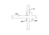
図7は、第1の例示の副行換気バイパストラップシステム700を示している。システム700は、トラップ702、空気運搬導管704及びフィルタ/一方向弁706を有している。空気運搬導管704は、フィルタ/一方向弁706を通って人の肺708とトラップ702を互いに流体連通させる。単一の導管704が示されているが、2以上の高副行換気領域があるかどうかが判定されると、多数の導管を各肺708内に利用することができる。 FIG. 7 illustrates a first exemplary collateral ventilation
トラップ702は、人の片方又は両方の肺708からの吐出物を集める任意適当な装置であってよい。本質的には、トラップ702は単に、肺からの排出物、例えば肺中に堆積する場合のある粘液又は他の流体を一時的に貯蔵する格納容器である。トラップ702は、任意適当な形状のものであってよく、また任意適当な金属又は非金属材料から作られたものであってよい。好ましくは、トラップ702を軽量の非腐食性材料から作るべきである。加うるに、トラップ702は、有効且つ効果的なクリーニングが可能であるような仕方で設計されるべきである。例示の一実施形態では、トラップ702は、トラップ702が一杯になると、除去できる使い捨てライナを有するのがよい。トラップ702は、トラップ702を空にすべきか又は清浄にすべき時期を容易に決定できるよう透明な材料から作られたものであるのがよく、或いは表示窓を有するのがよい。軽量のトラップ702を利用すると、患者の移動性が高くなる。
フィルタ/一方向弁706を任意適当な手段でトラップ702に取り付けるのがよく、かかる手段としては、圧縮機の接続において一般的に利用されているねじ継手又は圧縮型継手が挙げられる。フィルタ/一方向弁706は、多くの機能を果たす。フィルタ/一方向弁706により、トラップ702に流体吐出物及び固形粒状物を維持した状態で人の片方又は両方の肺708からの空気がトラップ702から流出することができる。このフィルタ/一方向弁706は本質的に、トラップ702内の圧力を人の片方又は両方の肺708の内部の圧力よりも低く保って肺708からトラップ702への空気の流れがこの一方向に維持されるようにする。フィルタ/一方向弁706のフィルタ部分は、空気中に浮遊するが、清浄な空気を通過させて周囲環境中へ抜き出すことができるような特定サイズの粒状物を捕捉するよう設計されたものであるのがよい。フィルタ部分は又、呼息空気の水分を減少させるような仕方で設計されたものであるのがよい。 Filter / one-
空気運搬導管704は、トラップ702をフィルタ/一方向弁706を介して患者の片方又は両方の肺708に連結している。空気運搬導管704は、空気中に含まれているガスに対し耐性のある任意適当な生体適合性管類から成るのがよい。空気運搬導管704は、内径が約1/16インチ(1.59mm)〜約1/2インチ(12.7mm)、より好ましくは約1/8インチ(3.18mm)〜約1/4インチ(6.35mm)の管類から成る。フィルタ/一方向弁706は、空気が空気運搬導管704を通って片方又は両方の肺708から流れ出ることができるが、トラップ702から肺708へは戻らないようにする任意適当な弁であってよい。例えば、単一の逆止弁を利用するのがよい。空気運搬導管704を任意適当な手段によりフィルタ/一方向弁706に連結するのがよい。好ましくは、迅速解除機構がトラップを保守のために容易に取り外すことができるよう利用される。図7に示すように、空気運搬導管704は、最も高い度合いの副行換気が存在すると判定された部位で肺708を通過している。2以上の部位を突き止めた場合、多数の空気運搬導管704を利用することができる。フィルタ/一方向弁706への多数の空気運搬導管704の連結は、任意適当な手段によって達成でき、かかる手段としては、スキューバダイビング用調整器で利用されるものと類似したタコ型装置が挙げられる。 An
空気運搬導管704は好ましくは、いったん定位置に配置されると、圧潰に耐えると共に抵抗することができる。空気が導管704を通って移動するので、もし導管が圧潰して回復できないならば、システムの有効性は減少する。したがって、圧潰回復性材料を空気運搬導管704に組み込むのがよい。その目的は、かかる空気運搬導管を圧潰しても回復可能にすることにある。多くの適当な材料を利用することができる。例えば、ニチノールを導管704に組み込むと、導管に圧潰抵抗性及び圧潰回復性が与えられることになる。 The
導管704の端部のところに設けられた拡張可能な特徴部は、導管704と肺胸膜の接触状態を維持すると共に導管704を肺胸膜に密着させるのを助けるために利用できる。導管704に組み込まれたニチノールにより、導管704を圧縮状態で送達し、次にこれを拡張状態に展開させて導管を定位置に固定することができる。導管の端部のところに設けられた肩も又、挿入の機械的停止部となると共に接着剤/シーラントが次に詳細に説明するように接合する領域を提供することができる。 An expandable feature provided at the end of the
例示の副行換気バイパストラップシステム700が機能するようにするために、空気運搬導管704が胸腔及び肺708を通過する場所に好ましくは気密シールが維持される。このシールは、肺の膨張/機能性を持続するために維持される。シールが破られると、空気は胸腔に入って肺が上述したように潰れるようにする場合がある。このシールを形成する例示の一方法は、肺の内臓側胸膜と胸腔の内壁との間に癒着部を形成する段階を有する。これは、化学的方法、外科的方法又は放射線療法を用いて達成でき、化学的方法としては、刺激原、例えばドキシサイクリン及び(又は)ブレオマイシンが挙げられ、外科的方法としては、胸膜切除術又はホロスコープタルク胸膜癒着術が挙げられ、放射線療法としては、放射性金又は外部放射線が挙げられる。これら方法は全て、胸膜癒着術に関する技術分野において知られている。別の例示の変形実施形態では、空気運搬導管704と外側胸膜層との間の密封接合法としては、空気運搬導管704の付着/密着を助ける種々のグルーの使用が挙げられる。現在、フォーカル・インコーポレイテッドは、密着又は密封目的で肺に用いられることが意図された“Focal/Seal-L”という商標名で入手できるシーラントを市場に出している。Focal/Seal-Lは、シーラントを硬化させるために光で活性化される。サージカル・シーランツ・インコーポレイテッドによって製造されている“Thorex”という商標名で市販されている別のシールは、肺密着適応用として臨床試験を現在行っている。Thorexは、二液を混合した後に設定硬化時間を有する二液型シーラントである。 In order for the exemplary collateral ventilation
胸腔中に開口部を形成することは、多くの方法で達成できる。例えば、開放式胸部手技、胸骨切開術又は開胸術を用いて達成できる。変形例として、侵襲性の低い腹腔鏡術を用いて達成してもよい。利用する手技とは無関係に、肺が固体接着剤表面を維持するために少なくとも部分的に鼓張された状態でシールが構成されるべきである。すると、導管コンポーネントと肺胸膜面との間に接合部を適当に形成した後、開口部を作ることができる。開口部は、過膨張肺の十分な除圧をもたらすために断面積が適当なものであることが必要である。この開口部を上述したように多種多様な技術、例えば切断、穿孔、拡張、ブラントジセクション、高周波エネルギ、超音波エネルギ、マイクロ波エネルギ又はクライオブレーティブ(cryoblative )エネルギを用いて形成することができる。 Creating an opening in the thoracic cavity can be accomplished in a number of ways. For example, it can be accomplished using an open chest procedure, sternotomy or thoracotomy. Alternatively, it may be achieved using less invasive laparoscopic surgery. Regardless of the procedure utilized, the seal should be configured with the lungs at least partially taut to maintain a solid adhesive surface. An opening can then be made after the joint is properly formed between the conduit component and the pleural surface of the lung. The openings need to be of a suitable cross-sectional area to provide sufficient decompression of the hyperinflated lung. The opening can be formed using a wide variety of techniques as described above, such as cutting, piercing, dilating, blunt dissection, radio frequency energy, ultrasonic energy, microwave energy or cryoblative energy. .
空気運搬導管704を酸素運搬導管704に関して上述すると共に図2〜図5に示した手段及び方法のうち任意のものにより換気バイパス部位で皮膚に密着させることができる。 The
作用を説明すると、人が呼息した場合、肺内圧力はトラップ702内圧力よりも高い。したがって、肺の副行性の高い領域中の空気は、空気運搬導管704を通ってトラップ702に流れることになる。この作用により、人は、容易且つ完全に呼息することができる。 In operation, when a person exhales, the pressure in the lungs is higher than the pressure in the
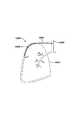
図8は、別の例示の副行換気バイパスシステム800を示している。この例示の実施形態では、生まれつきの気道ではなく気管を利用して取り込み空気を除去する。図示のように、第1の導管802が、患者の気管804又は他の近位気道(気管支を含む)から患者の体外の位置まで延びている。第2の導管806が継手808を介して第1の導管802に連結されており、この第2の導管は、胸壁810を通り、そして最も高い度合いの副行換気を呈すると判定された部位のところで肺812を通過している。2以上の部位が高度の副行換気を呈すると判定された場合、多数の導管を利用することができる。作用を説明すれば、患者が呼息すると、肺内の圧力は気管804内の圧力よりも高く、従って肺の高度に副行された領域中の空気は、第1の導管802及び第2の導管806を通って気管804に移動し、そして正常に呼息された空気の状態で患者の鼻及び口から出る。 FIG. 8 illustrates another exemplary collateral
第1の導管802及び第2の導管806は、吸息空気及び呼息空気中に含まれた種々のガス及び他の成分に対し耐性のある任意適当な生体適合性管類から成るのがよい。先に説明した実施形態の場合と同様、第1の導管802及び第2の導管806は、内径が約1/16インチ(1.59mm)〜約1/2インチ(12.7mm)、より好ましくは約1/8インチ(3.18mm)〜約1/4インチ(6.35mm)の管類から成る。 The
気管804への第1の導管802の連結は、任意適当な気密シールから成るものであってよい。例えば、気管804と第1の導管802との間の流体連通を気管切開術について確立した仕方と同一の仕方で確立するのがよい。加うるに、上述したように、副行換気バイパスシステム800が機能するようにするために、第2の導管806が胸壁810を通って肺812内に入る場所に好ましくは気密シールが維持される。この気密シールを形成する例示の方法は、肺の内臓側胸膜と壁側胸膜との間に癒着部を形成する段階を有する。これは、化学的方法、外科的方法又は放射線療法を用いて達成でき、化学的方法としては、刺激原が挙げられ、外科的方法としては、胸膜切除術又は胸腔鏡タルク胸膜癒着術が挙げられ、放射線療法としては、放射性金又は外部放射線が挙げられる。 The connection of the
胸壁に開口部を形成することは、多くの方法で達成できる。例えば、開放式胸部手技、胸骨切開術又は開胸術を用いて達成できる。変形例として、侵襲性の低い腹腔鏡術を用いて達成してもよい。利用する手技とは無関係に、肺が固体接着剤表面を維持するために少なくとも部分的に鼓張された状態でシールが構成されるべきである。すると、導管コンポーネントと肺胸膜面との間に接合部を適当に形成した後、開口部を作ることができる。開口部は、過膨張肺の十分な除圧をもたらすために断面積が適当なものであることが必要である。この開口部を上述したように多種多様な技術、例えば切断、穿孔、拡張、ブラントジセクション、高周波エネルギ、超音波エネルギ、マイクロ波エネルギ又はクライオブレーティブ(cryoblative )エネルギを用いて形成することができる。 Creating an opening in the chest wall can be accomplished in a number of ways. For example, it can be accomplished using an open chest procedure, sternotomy or thoracotomy. Alternatively, it may be achieved using less invasive laparoscopic surgery. Regardless of the procedure utilized, the seal should be configured with the lungs at least partially taut to maintain a solid adhesive surface. An opening can then be made after the joint is properly formed between the conduit component and the pleural surface of the lung. The openings need to be of a suitable cross-sectional area to provide sufficient decompression of the hyperinflated lung. The opening can be formed using a wide variety of techniques as described above, such as cutting, piercing, dilating, blunt dissection, radio frequency energy, ultrasonic energy, microwave energy or cryoblative energy. .
導管802,806を任意公知の方法により換気バイパス部位のところで皮膚に密着するのがよく、かかる方法としては、図2〜図5を参照して上述した方法が挙げられる。胸外コンポーネント及び導管806の連結は、薬剤、化学物質、作用薬又は感染の恐れを無くし又は実質的に軽減させる他の手段から成るのがよい。 The
第1の導管802と第2の導管806を連結する継手808は、気密シールを形成する任意適当な器具から成るものであってよい。継手808は、任意形式のねじ込み式又は非ねじ込み式ユニオン、圧縮型継手に類似した圧縮継手、又は気密シールを形成し、継手808の2つの端部相互間の迅速な解除を可能にする任意他の適当な器具から成るものであってよい。この種の設計により、システム800の定期的な保守、例えば導管802,806を掃除するための容易な接近が可能になる。継手808は体外に位置しているので、システム800の体内コンポーネントへの接近が容易になる。本質的に、体外からのシステム800への接近により、患者に追加のストレス及び危険を与えることなくシステム800の保守及び診断/観察が可能になる。また、これにより医師にとっての時間の浪費が少なくなる。 The
図9は、上述した例示の副行換気バイパスシステム800の例示の変形実施形態を示している。この例示の実施形態では、システム900は、外部に設けられたアクセスポート908を有している。図示のように、導管902が、患者の気管904又は他の近位気道(気管支を含む)から患者の体内の適当な通路を通り、次に、最も高い度合いの副行換気を呈すると判定された部位のところで肺912を通過している。上述したように、2以上の部位が高度の副行換気を呈すると判定された場合、多数の導管を利用することができる。体内の所望の位置では、アクセスポート908を導管902とインラインに設けてアクセスポート908の少なくとも一部が体外で接近可能であるようにするのがよい。本質的に、アクセスポート908により、患者又は医師は、上述したようにシステム900の保守及び診断/観察のためにポートを開いてシステム900に接近することができることが必要である。 FIG. 9 illustrates an exemplary variation of the exemplary collateral
アクセスポート908は、閉じられると気密シールを形成し、開かれると導管902への容易な接近を可能にする任意適当な器具から成るものであってよい。アクセスポート908は、種々の機能を実行するよう利用できる他のコンポーネントを連結する種々の弁構造及びコネクタから成っていてもよい。例えば、必要ならば酸素を直接患者の肺912に供給するのがよい。この場合、酸素が肺912をバイパスするのを阻止し、真っ直ぐに気管904に流れるようにするために弁が必要な場合がある。
残りのコンポーネントは全て上述したものと同一であるのがよい。加うるに、全てのシールを上述したように達成することができる。 All remaining components should be identical to those described above. In addition, all seals can be achieved as described above.
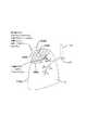
更に別の例示の変形実施形態では、図9に示す胸外アクセスポート908を皮膚のすぐ下に設けてこれが経皮的に接近可能であるようにしてもよい。本質的に、アクセスポートは、本当の意味では胸外に位置するものではなく、皮膚の下に設けられていて、胸外的に接近可能である。この例示の実施形態では、接近は、容易に接近可能であるとは言えないが、アクセスポイントは、上述した例示の実施形態の場合よりも別個独立のままである。図10は、この例示の実施形態を示している。 In yet another exemplary variation, the
図10に示すように、副行換気バイパスシステム1000は、導管1002を有し、この導管1002は、患者の気管1004又は他の近位気道(気管支を含む)から患者の体内の適当な通路を通り、次に、最も高い度合いの副行換気を呈すると判定された部位のところで肺1012を通過している。上述したように、2以上の部位が高度の副行換気を呈すると判定された場合、多数の導管を利用することができる。体内の所望の位置では、アクセスポート1008を導管1002とインラインに設けるのがよい。アクセスポート1008は、経皮的手段による接近を可能にする任意適当な器具から成るものであってよい。残りのコンポーネントは全て上述したものと同一であるのがよい。加うるに、全てのシールを上述したように達成することができる。 As shown in FIG. 10, the collateral
上述の例示の実施形態の各々において、導管の気管側端部から肺への流れを阻止するよう働く追加のコンポーネントを設けるのがよいことに注目することは重要である。例えば、1以上の弁をシステム全体に組み込んで粘液及び他の物質が肺に入り又は再び入るのを阻止するようにするのがよい。システムの主な機能は、呼息を可能にすることにある。理論的には、気腫のある患者は、吸息ではなく呼息に対する抵抗が大きい。任意適当な弁、例えば一方向逆止弁を利用するのがよい。 It is important to note that in each of the above-described exemplary embodiments, additional components that serve to block flow from the tracheal end of the conduit to the lungs may be provided. For example, one or more valves may be incorporated into the entire system to prevent mucus and other substances from entering or reentering the lungs. The main function of the system is to enable exhalation. Theoretically, patients with emphysema have greater resistance to exhalation rather than inspiration. Any suitable valve may be utilized, such as a one-way check valve.
上述したように、肺気腫により肺組織の破壊が生じ、それにより肺が反跳する能力が減少すると共に気道の半径方向支持作用が失われる。その結果、肺組織の弾性反跳が失われることは、気腫のある人が完全には呼息できないという一因となる。また、気道の半径方向支持が失われると、呼吸の呼息相中、潰れ現象が生じる場合がある。この潰れ現象は又、人が完全には呼息できない度合いを強める。呼息しにくさが強まると、肺中の残気量も又増大する。すると、これにより肺は人が短く浅い呼吸しかすることができない過膨張状態になる。本質的に、空気は効果的には排出されず、淀み空気が肺中に溜まる。淀み空気がいったん肺中に溜まると、人から酸素が奪われる。 As mentioned above, emphysema causes destruction of lung tissue, thereby reducing the ability of the lungs to recoil and losing radial support of the airways. As a result, the loss of elastic recoil of the lung tissue contributes to the inability of a person with emphysema to exhale completely. Also, the loss of radial support of the airways may cause a collapse event during the expiratory phase of breathing. This collapsing phenomenon also increases the degree to which a person cannot exhale completely. As the difficulty of exhaling increases, the amount of residual air in the lungs also increases. This then causes the lungs to become hyperinflated, where a person can only breathe short and shallow. In essence, air is not effectively exhausted and stagnant air accumulates in the lungs. Once stagnant air accumulates in the lungs, oxygen is deprived of the person.
気腫肺減量術は、片方又は両方の肺の1又は複数の部分の除去を含む極めて外傷性の高い手技である。過膨張状態にある片方又は両方の肺の部分を除去することにより、肺の機能は、多くの機序により向上する場合があり、かかる機序としては、弾性反跳の向上、換気血流不適合の矯正及び呼吸効率の向上が挙げられる。本質的に、気腫組織容量を減少させると、健常な組織は良好に換気される。しかしながら、気腫肺減量術は、後で詳細に説明するような多くの潜在的な危険を伴っている。 Emphysema pulmonary debulking is a highly traumatic procedure involving the removal of one or more parts of one or both lungs. By removing one or both parts of the lung that are overinflated, lung function may be enhanced by a number of mechanisms, including improved elastic recoil, inadequate ventilation and blood flow. And improving respiratory efficiency. In essence, reducing emphysema tissue volume results in good ventilation of healthy tissue. However, emphysema pulmonary debulking involves a number of potential risks, as will be described in detail below.
図7に示す副行換気バイパストラップシステム700及び図8に示す副行換気バイパスシステム800は、片方又は両方の肺の中に取り込まれた空気が生まれつきの気道をバイパスしてこれを格納容器又は周囲環境に排出できるようにする副行換気現象を利用している。しかしながら、例示の変形実施形態では、副行換気バイパスと同様に働き、気腫肺減量術と整合した結果をもたらす器械を本明細書において開示する。本質的に、この例示の実施形態では、本発明は、肺減圧を助ける器械及び方法に関する。換言すると、本発明は、気腫肺中の取り込み空気の除去及び小さな容積に圧縮される気腫領域の維持を行う肺減圧補助器械及び方法に関し、その結果、健常な肺組織は胸腔中の換気量が多くなる。この器械の効果は、気腫肺減量術の効果とほぼ同じである。 The collateral ventilation
本発明の例示の肺減圧補助器械を患者の体内に巧妙に配置してこれが患者の片方又は両方の肺及び外部環境と流体連通状態をなすようにするのがよい。この器械により、空気を生まれつきの気道を通って片方又は両方の肺から呼出することができ、他方片方又は両方の肺の過膨張部分中の取り込み空気を除去するのを助ける。気腫肺減量術は、相当多くの症例において、この手技を受ける患者が肺移植の候補者であることから排除されるようにする極めて高い浸襲性及び外傷性の手技である。本発明の装置は、肺容積を気腫肺減量術と同様に減少させると共に患者が肺移植の生存候補者のままであるようにすることができる低侵襲手技を可能にする。 The exemplary pulmonary decompression assist device of the present invention may be cleverly positioned within a patient's body so that it is in fluid communication with one or both lungs and the external environment of the patient. This instrument allows air to be exhaled from one or both lungs through the natural airway, while helping to remove entrained air in the hyperinflated portion of one or both lungs. Emphysema pulmonary debulking is a very highly invasive and traumatic procedure that, in quite a number of cases, allows patients undergoing this procedure to be excluded from being candidates for lung transplantation. The device of the present invention allows for a minimally invasive procedure that can reduce lung volume in a manner similar to emphysema pulmonary debulking and leave patients a viable candidate for lung transplantation.
例示の肺減圧器械は、取り込み空気が片方又は両方の肺から出ることができるように片方又は両方の肺の内部と片方又は両方の肺の外部の領域との間に十分な圧力差を生じさせる多くの公知の方法を利用することができる。この器械は、任意適当な装置、例えばポンプ又はファン、或いは圧力差を生じさせる任意他の手段であってよい。気腫の副行空気流及び領域を空気がこの領域を再び膨らますことができるよう位置させる場合、この器械を気腫組織の小さな肺容積部を維持するよう片方又は両方の肺から空気を連続的に引き出すよう構成されたものであるのがよい。この器械は、片方又は両方の肺中の気腫組織の圧縮状態を維持するために患者の体内に無期限に留置されたままであるのがよい。加うるに、この器械の清浄さ及び患者の安全性を維持するために、この器械を使い捨て器械として構成し、種々の時間間隔で交換するのがよい。加うるに、容易に接近可能な器械の部分を使い捨てに作るのがよい。変形例として、かかる器械を容易な取り外し、容易な掃除及び容易な交換ができるよう構成されたものであってよい。 The exemplary pulmonary decompression device creates a sufficient pressure differential between the interior of one or both lungs and the area outside of one or both lungs so that entrained air can exit one or both lungs. Many known methods are available. The instrument may be any suitable device, such as a pump or fan, or any other means for creating a pressure differential. If the collateral airflow and area of emphysema is positioned so that air can re-inflate this area, the instrument may be continuously pumped from one or both lungs to maintain a small lung volume of emphysema tissue. It is good that it is constituted so that it may be pulled out. The device may be left indefinitely in the patient to maintain compression of the emphysema tissue in one or both lungs. In addition, in order to maintain the cleanliness and patient safety of the device, the device may be configured as a disposable device and replaced at various time intervals. In addition, parts of the instrument that are easily accessible may be made disposable. Alternatively, the device may be configured for easy removal, easy cleaning and easy replacement.
図11を参照すると、本発明の例示の肺減圧器械1100が示されている。本明細書において説明するように、一般的に、肺の最も副行的に換気される一又は複数の領域に接近するよう肺の外胸膜を穿通するのに最適な場所があると共にかかる一又は複数の領域の場所を突き止める又は確認する種々の方法がある。所望の場所をいったん突き止めると、減圧器械1100を肺1102中へ挿入するのがよい。減圧器械1100を肺1102中へ挿入して配置すると、壁側胸膜と内臓側胸膜の気密シールを形成するのに特に有利である。適正な気密シールが減圧器械と壁側胸膜と内臓側胸膜との間に形成されなければ、気胸症が生じる場合がある。 Referring to FIG. 11, an exemplary
注目すべき重要なこととして、高度に副行的な領域から取り込み空気を除去するために1以上の器械を各肺に利用するのがよい。変形例として、多数の導管を備えた単一の器械を利用してもよい。図11に示すように、減圧器械1100は肺1102内の最高副行的換気部1104の領域内に配置される。例示の一実施形態では、減圧器械1100の第1の部分1106だけが肺1102内に配置され、減圧器械1100の第2の部分1108は、肺1102の外部に固定される。器械1100の密封を本明細書に記載される器械及び方法のうち任意のものに従って行うことができる。 It is important to note that one or more instruments may be utilized on each lung to remove entrained air from highly collateral areas. Alternatively, a single instrument with multiple conduits may be utilized. As shown in FIG. 11, the
第2の部分1108の少なくとも一部は、患者の体外に位置している。患者の体外に位置する第2の部分1108の部分は、任意適当な場所で体から出るのがよい。例示の一実施形態では、第2の部分1108の部分は、胸を通って体から出て、かくしてこれを本明細書に記載する装置及び方法の任意のものに従って密封するのがよい。 At least a portion of
第1の部分1106は、肺1102からの空気の流れを容易にするよう構成された任意適当な生体適合性材料から作られたものであるのがよい。例えば、第1の部分1106は、寸法、材質及び構造が本明細書に記載する他の導管とほぼ同じ導管であるのがよい。第2の部分1108を任意適当な手段で第1の部分1106に連結するのがよく、かかる手段としては、ねじ込み式ユニオン又は圧縮型継手が挙げられる。第2の部分1108は、肺の過膨張部分1104から第1の部分1106を通って空気を引き出し、これを患者の体外に差し向ける装置のハウジングを構成している。この装置は、空気が肺1102から容易に流れるよう肺1102の内部と外部との間に圧力差を生じさせる任意適当な装置であってよい。この装置は、超小型ポンプ又はファンから成るのがよい。超小型ポンプ又はファンに任意適当な手段で給電することができ、かかる手段としては、電池又は充電可能電池が挙げられる。上述の例示の実施形態では、超小型ポンプ又はファン及びその電源をハウジング内に完全に収納するのがよい。他の例示の変形実施形態では、ポンプ/ファン又は電源のうち1以上を第2の部分1108から見て遠くに配置してもよい。例えば、第2の部分1108は単に、一端が第1の導管に着脱自在に連結され、第2の端部が空気を肺1104の疾患部分から引き出す装置に着脱自在に連結された第2の導管であってもよい。
図11に示す例示の実施形態では、空気を肺1104の疾患部分から引き出す装置及びその関連の電源は第2の部分1108内に収納されている。この設計により、患者にとって最も大きな自由度が得られる。種々の公知の超小型真空ポンプ又はファンを用いると、空気を肺1104の疾患部分から連続的に引き出すことができ、それにより気腫組織容積を減少させると共に健常な組織が良好に換気できるようになる。超小型ファン/ポンプ及び関連電源は、別個の部品又は単一の部品であってもよい。これら超小型装置は、空気を或る1つの場所から引き出し、これを別の場所に逃がす微小電子機械システム、即ちMEMS又は任意他の適当な装置であってよい。減圧器械1100は、容易に保守されるよう設計されたものであることが必要である。例えば、第2の部分1108は、これを取り外すことができ、電源を充電することができ、そして他の部品を掃除して交換できるよう構成されたものであるのがよい。変形例として、第2の部分1108は、単に使い捨てであってもよい。 In the exemplary embodiment shown in FIG. 11, the device for extracting air from the diseased portion of
電源は、電力を長期間にわたって連続的に供給する任意適当な手段であってよい。電源は、電池、充電式電池、電力を機械的な歪みから発生させる発電装置又は任意他の適当な装置であってよい。加うるに、真空を発生させるファン又はポンプ以外に、僅かな圧力差を生じさせるために或る形式の切換え要素を利用してもよい。 The power source may be any suitable means for providing power continuously over an extended period of time. The power source may be a battery, a rechargeable battery, a generator that generates power from mechanical strain, or any other suitable device. In addition, other than a fan or pump that creates a vacuum, some type of switching element may be used to create a small pressure differential.
したがって、肺組織の切除ではなく、減圧器械は、取り込み空気を肺の気腫部分から除去し、気腫部分を圧縮状態又は小さな容積の状態に維持し、それにより胸腔内においてより大きな容積の健常な肺組織が換気できるようにする。図12Aは、空気を肺1200の過膨張部分1202から除去する減圧器械1100を示している。図示のように、この肺では、肺1200の過膨張又は気腫部分1202は、肺1200の健常な部分又は区分1204よりも大きい。器械1100が溜まった又は取り込まれた空気を除去し続けると、肺1200の過膨張部分1202の容積が収縮し、それにより十分に換気する健常な部分1204の余地が広くなり、それにより図12Bに示すように容積が増加する。 Thus, rather than ablation of the lung tissue, the decompression device removes the entrained air from the emphysema portion of the lung and maintains the emphysema portion in a compressed or small volume state, thereby increasing the volume of the healthy volume in the thoracic cavity. Allow for adequate lung tissue ventilation. FIG. 12A shows a
副行換気現象を用いて疾患のある範囲からの呼息流を増大させる上述の例示の器械及び手技では、肺の最も副行的な1又は複数の換気領域に接近するために肺の外側胸膜を穿通するのに最適な場所がある。上述のように、肺の最も副行的に換気される1又は複数の領域の場所を突き止めるのに種々の方法が存在している。肺に取り込まれた空気が生まれつきの気道をバイパスすることができ、それによりかかる空気を体外に排出できるよう器械の装置又はコンポーネントが機能するので、壁側(胸壁)胸膜と内臓(肺)側胸膜の気密シールを提供するのが特に有利である。装置と壁側胸膜と内臓側胸膜との間に適正な気密シールが作られなければ、気胸症(肺の潰れ)が生じる場合がある。本質的には、肺を穿刺し、装置を挿入する環境ではどれにおいても、好ましくは気密シールを維持すべきである。 In the above-described exemplary apparatus and procedure for increasing expiratory flow from a diseased area using collateral ventilation, the outer pleura of the lung to access the most collateral one or more ventilation areas of the lung. There is a perfect place to penetrate. As mentioned above, various methods exist for locating the most collaterally ventilated region or regions of the lung. The parietal (chest wall) pleura and the visceral (lung) pleura, as the devices or components of the instrument function so that the air entrained in the lungs can bypass the natural airways, thereby allowing such air to escape outside the body. It is particularly advantageous to provide a hermetic seal. If a proper hermetic seal is not created between the device and the parietal and visceral pleuras, pneumothorax (collapse of the lungs) may occur. In essence, a seal should be maintained, preferably in any environment in which the lung is punctured and the device inserted.
気密シールを達成する一方法は、胸膜癒着術、即ち胸膜腔の閉塞による方法である。多くの胸膜癒着法があり、かかる癒着法としては、化学的、外科的及び放射線胸膜癒着術が挙げられる。化学的胸膜癒着術では、薬剤、例えばテトラサイクリン、ドキシサイクリン、ブレオマイシン又は窒素マスタードを利用することができる。外科的胸膜癒着術では、胸膜切除術又は胸腔鏡タルク手技を行うのがよい。放射線手技では、放射性金又は外部放射線を利用するのがよい。本発明では、化学的胸膜癒着術が利用される。 One way to achieve a hermetic seal is by pleurodesis, ie, by closing the pleural space. There are a number of pleurodesis methods, including chemical, surgical and radiation pleurodesis. For chemical pleurodesis, drugs such as tetracycline, doxycycline, bleomycin or nitrogen mustard can be utilized. For surgical pleurodesis, a pleurectomy or thoracoscopic talc procedure may be performed. Radiation procedures may utilize radioactive gold or external radiation. The present invention utilizes chemical pleurodesis.
上述した器械の適正な気密シールを確保するために化学物質又は薬剤を局所化された仕方で投与する例示の器械及び方法について以下に説明する。化学物質、薬剤及び(又は)製剤は、壁側胸膜と内臓側胸膜との間に胸膜癒着部を形成するために用いられ、器械の一コンポーネントが特定領域を穿通するが、結果として気胸が生じないようにする。胸膜腔中に胸膜癒着部を形成するために利用できる化学物質、薬剤及び(又は)製剤には多くのものがある。化学物質、薬剤及び(又は)製剤としては、タルク、テトラサイクリン、ドキシサイクリン、ブレオマイシン及びミノサイクリンが挙げられる。 Exemplary devices and methods for administering chemicals or agents in a localized manner to ensure a proper hermetic seal of the devices described above are described below. Chemicals, drugs and / or preparations are used to create a pleurodesis between the parietal and visceral pleuras, where one component of the instrument penetrates a specific area, resulting in pneumothorax Not to be. There are many chemicals, agents and / or formulations available for forming pleurodesis in the pleural cavity. Chemicals, drugs and / or formulations include talc, tetracycline, doxycycline, bleomycin and minocycline.
例示の一実施形態では、化学物質、薬剤及び(又は)製剤を局所領域に投与してその領域中に胸膜癒着部を形成するために改造型薬物投与カテーテルを利用するのがよい。この例示の実施形態では、胸膜癒着部を形成し、次に導管704を図7に示すように胸膜癒着部の領域を通って肺708内に位置決めする。薬物投与カテーテルは、局所胸膜癒着部を形成するための低侵襲手段となる。図13を参照すると、本発明に従って利用できる薬物投与カテーテルの例示の実施形態が示されている。多くの薬物投与カテーテルを利用することができる。加うるに、カテーテルの遠位先端部は、任意適当な寸法、形状又は形態のものであってよく、それにより任意の寸法、形状又は形態の胸膜癒着部を形成することができる。 In one exemplary embodiment, a modified drug delivery catheter may be utilized to administer a chemical, drug and / or formulation to a local area to form a pleurodesis in that area. In this exemplary embodiment, the pleurodesis is formed and then the
図13に示すように、カテーテル1300を遠位端部1302が胸壁1308と肺1306との間の胸膜腔1304内に位置決めされるよう患者の体内に挿入する。図示の例示の実施形態では、カテーテル1300の遠位端部1302は、化学物質、薬剤及び(又は)製剤を矢印1310で示すように実質的に円形の形をした内周部に向かって放出できる実質的に円形の形をしている。カテーテル1300の遠位端部1302は、化学物質、薬剤及び(又は)製剤を放出できるようにする複数の穴又は開口部1312を有している。上述のように、遠位端部1302は、任意適当な寸法、形状又は形態のものであるのがよい。化学物質、薬剤及び(又は)製剤をいったん投与すると、カテーテル1300を抜去して導管704(図7)の植え込みを可能にするのがよい。変形例として、カテーテル1300を利用すると導管704を送り易くすることができる。 As shown in FIG. 13, the
カテーテル1300の遠位端部又は先端部1302は好ましくは、胸膜腔内にいったん配備されると、その所望の寸法、形状及び(又は)形態を維持すべきである。これは、多くの方法で達成できる。例えば、カテーテル1300の遠位端部1302の構成材料を、これがカテーテル1300の挿入のための或る程度の可撓性を有すると共にいったん配備されるとその元の又はプログラムされた形状に戻るよう或る程度の形状記憶性を有するよう選択するのがよい。これら特性を持つ多くの生体適合性ポリマーを利用することができる。変形実施形態では、別の材料を利用してもよい。例えば、形状記憶特性を持つ金属材料をカテーテル1300の遠位端部1302に組み込んでもよい。この金属材料としては、ニチノール又はステンレス鋼が挙げられる。加うるに、金属材料は、放射線不透過性であるのがよく、或いは放射線不透過性マーカを有するのがよい。放射線不透過性材料又は放射線不透過性マーカを設けることにより、カテーテル1300をX線透視法下で視認することができ、かかるカテーテルは、カテーテル1300が最高副行換気の場所に位置する時期を判定するのを助ける。 The distal end or
別の例示の変形実施形態では、局所薬物投与器械を利用して胸膜癒着用化学物質、薬剤及び(又は)製剤を投与することができる。この例示の実施形態では、胸膜癒着部を形成し、次に導管704を図7に示すように胸膜癒着部を通って肺708内に位置決めする。この例示の実施形態では、化学物質、薬剤及び(又は)製剤を植え込み可能な医用器具に付着させることができる。次に、医用器具を特定の部位で胸膜腔内に植え込み、そして化学物質、薬剤及び(又は)製剤をこれから放出して胸膜癒着部を形成し又は構成する。 In another exemplary variation, a pleurodesis chemical, agent and / or formulation may be administered using a local drug delivery device. In this exemplary embodiment, the pleurodesis is formed, and then the
上述の化学物質、薬剤及び(又は)製剤のうち任意のものを医用器具に付着させることができる。化学物質、薬剤及び(又は)製剤を任意適当な仕方で医用器具に付着させることができる。例えば、多くの周知の方法を利用して化学物質、薬剤及び(又は)製剤を器械に塗布することができ、かかる方法としては、スピンコーティング法、吹付け法又は浸漬法が挙げられ、又、別法として、これらを医用器具の表面に被着されたポリマーマトリックス中に混ぜ込むことができ、これらを医用器具の外面中に含浸させることができ、これらを医用器具に設けられた穴又はチャンバ内に入れることができ、これらを医用器具の表面に塗布し、次に化学物質、薬剤及び(又は)製剤の制御された放出のための拡散バリヤとして働くポリマー層で被覆することができ、これらを医用器具を形成する材料中へ直接混ぜ込むことができ、或いは上述の方法の任意の組合せが用いられる。別の変形実施形態では、医用器具が劣化すると化学物質、薬剤及び(又は)製剤を溶出する生分解性材料で医用器具を形成してもよい。 Any of the chemicals, agents and / or formulations described above can be attached to the medical device. The chemical, drug and / or formulation can be attached to the medical device in any suitable manner. For example, chemicals, drugs and / or formulations can be applied to an instrument using a number of well-known methods, including spin coating, spraying or dipping; Alternatively, they can be incorporated into a polymer matrix applied to the surface of the medical device, they can be impregnated into the outer surface of the medical device, and they can be embedded in holes or chambers provided in the medical device. Which can be applied to the surface of a medical device and then coated with a polymer layer that acts as a diffusion barrier for controlled release of chemicals, drugs and / or formulations. Can be incorporated directly into the material forming the medical device, or any combination of the above methods can be used. In another alternative embodiment, the medical device may be formed of a biodegradable material that elutes chemicals, drugs and / or formulations when the device degrades.
植え込み可能な医用器具は、任意適当な寸法、形状及び(又は)形態のものであってよく、任意適当な生体適合性材料を用いて形成できる。図14は、植え込み可能な医用器具1400の例示の一実施形態を示している。この実施形態では、植え込み可能な医用器具1400は、実質的に円筒形のディスク1400から成っている。ディスク1400は、胸壁1404と肺1406との間の胸膜腔1402内に位置決めされている。ディスク1400は、いったん定位置に配置されると、胸膜癒着部を形成する化学物質、薬剤及び(又は)製剤を放出する。放出速度は、上述の種々の方法のうち任意のもの、例えばポリマー拡散バリヤを用いることにより正確に制御できる。また、上述したように、ディスク1400をディスク1400がそれ自体分解し又は溶解すると、化学物質、薬剤及び(又は)製剤を溶出する生分解性材料から作られたものであるのがよい。ディスク1400の構成に利用される材料に応じて、非生分解性ディスク1400は、胸膜癒着部をいったん形成すると、胸膜腔1402からの取り出しを必要とする場合があるが、そうでない場合もある。例えば、ディスク1400は、胸膜癒着部と一体になる永続的インプラントであることが望ましい場合がある。 The implantable medical device can be of any suitable size, shape and / or configuration and can be formed using any suitable biocompatible material. FIG. 14 illustrates one exemplary embodiment of an implantable
先の例示の実施形態で説明したように、ディスク1400は、放射線不透過性マーカから成るのがよく、或いは放射線不透過性材料から作られたものであるのがよい。放射線不透過性マーカ又は材料により、ディスク1400を透視検査下で見ることができ、次に正確に位置決めすることができる。 As described in the previous example embodiment, the
更に別の例示の変形実施形態では、化学物質、薬剤及び(又は)製剤の流体特性を変更することができる。例えば、化学物質、薬剤及び(又は)製剤を粘性の高いものにすることができる。粘性の高い化学物質、薬剤及び(又は)製剤では、化学物質、薬剤及び(又は)製剤が胸膜腔内の所望の場所から動く恐れが低くなる。化学物質、薬剤及び(又は)製剤は、放射線不透過性成分を更に有してもよい。化学物質、薬剤及び(又は)製剤を放射線不透過性にすることにより、副行換気の最適場所に対する化学物質、薬剤及び(又は)製剤の場所の確認が可能になる。 In yet another exemplary variation, the fluid properties of the chemical, drug, and / or formulation can be altered. For example, chemicals, drugs and / or formulations can be made highly viscous. Highly viscous chemicals, drugs and / or formulations reduce the likelihood that the chemicals, drugs and / or formulations will move from a desired location within the pleural cavity. The chemical, drug and / or formulation may further comprise a radiopaque component. Making the chemical, drug and / or formulation radiopaque allows the location of the chemical, drug and / or formulation to be optimal for collateral ventilation.
上記において設計変更したような化学物質、薬剤及び(又は)製剤を標準の化学的胸膜癒着器械及び方法と関連して又は上述した例示の実施形態と関連して利用することができる。 Chemicals, agents and / or formulations as redesigned above may be utilized in connection with standard chemical pleurodesis machines and methods or in connection with the exemplary embodiments described above.
最も実用的で且つ好ましい実施形態と考えられる形態を開示したが、当業者であれば開示した特定の設計及び方法の変形例を想到でき、かかる変形例を本発明の精神及び範囲から逸脱することなく利用できることは明らかである。本発明は、開示した特定の構造には限定されず、特許請求の範囲に記載された本発明の範囲に属する全ての改造例を含むものである。 While the forms that are considered to be the most practical and preferred embodiments have been disclosed, those skilled in the art will appreciate variations of the particular designs and methods disclosed, which would depart from the spirit and scope of the invention. Obviously it can be used without. The invention is not limited to the particular structure disclosed, but includes all modifications that fall within the scope of the invention as set forth in the appended claims.
患者肺の過膨張部分を減圧する本発明の方法は、慢性閉塞性肺疾患、例えば気腫や慢性気管支炎により引き起こされる低酸素症を効果的に治療するために利用される長時間酸素治療システムを有効且つ効果的に実施するための手段として利用できる。 The method of the present invention for decompressing the hyperinflated portion of a patient's lung is a prolonged oxygen therapy system utilized to effectively treat chronic obstructive pulmonary disease, such as hypoxia caused by emphysema and chronic bronchitis. Can be used as a means for effectively and effectively performing the above.
100 長時間酸素治療システム
104 酸素運搬導管
106 一方向弁
108 肺
200,300,400,500,502 フランジ
1100 肺減圧器械
1102 肺
1104 最高の副行換気の領域
1106 肺減圧器械の第1の部分
1108 肺減圧器械の第2の部分100 Long term
Claims (3)
Translated fromJapaneseApplications Claiming Priority (2)
| Application Number | Priority Date | Filing Date | Title |
|---|---|---|---|
| US47399903P | 2003-05-29 | 2003-05-29 | |
| US10/850,022US7533667B2 (en) | 2003-05-29 | 2004-05-20 | Methods and devices to assist pulmonary decompression |
Publications (1)
| Publication Number | Publication Date |
|---|---|
| JP2004358248Atrue JP2004358248A (en) | 2004-12-24 |
Family
ID=33135333
Family Applications (1)
| Application Number | Title | Priority Date | Filing Date |
|---|---|---|---|
| JP2004159778APendingJP2004358248A (en) | 2003-05-29 | 2004-05-28 | Device and method for assisting pulmonary decompression |
Country Status (3)
| Country | Link |
|---|---|
| US (1) | US7533667B2 (en) |
| EP (1) | EP1481701A1 (en) |
| JP (1) | JP2004358248A (en) |
Families Citing this family (33)
| Publication number | Priority date | Publication date | Assignee | Title |
|---|---|---|---|---|
| US7811274B2 (en) | 2003-05-07 | 2010-10-12 | Portaero, Inc. | Method for treating chronic obstructive pulmonary disease |
| US7426929B2 (en) | 2003-05-20 | 2008-09-23 | Portaero, Inc. | Intra/extra-thoracic collateral ventilation bypass system and method |
| US7533667B2 (en) | 2003-05-29 | 2009-05-19 | Portaero, Inc. | Methods and devices to assist pulmonary decompression |
| US7252086B2 (en) | 2003-06-03 | 2007-08-07 | Cordis Corporation | Lung reduction system |
| US7377278B2 (en) | 2003-06-05 | 2008-05-27 | Portaero, Inc. | Intra-thoracic collateral ventilation bypass system and method |
| US7682332B2 (en) | 2003-07-15 | 2010-03-23 | Portaero, Inc. | Methods to accelerate wound healing in thoracic anastomosis applications |
| US7670282B2 (en) | 2004-06-14 | 2010-03-02 | Pneumrx, Inc. | Lung access device |
| EP3542736A1 (en) | 2004-06-16 | 2019-09-25 | PneumRx, Inc. | Intra-bronchial lung volume reduction system |
| CA2570261C (en) | 2004-07-08 | 2014-06-10 | Pneumrx, Inc. | Pleural effusion treatment device, method and material |
| US7766891B2 (en) | 2004-07-08 | 2010-08-03 | Pneumrx, Inc. | Lung device with sealing features |
| US7398782B2 (en) | 2004-11-19 | 2008-07-15 | Portaero, Inc. | Method for pulmonary drug delivery |
| US8220460B2 (en) | 2004-11-19 | 2012-07-17 | Portaero, Inc. | Evacuation device and method for creating a localized pleurodesis |
| WO2006058195A2 (en) | 2004-11-23 | 2006-06-01 | Pneumrx, Inc. | Steerable device for accessing a target site and methods |
| US7824366B2 (en) | 2004-12-10 | 2010-11-02 | Portaero, Inc. | Collateral ventilation device with chest tube/evacuation features and method |
| US8104474B2 (en) | 2005-08-23 | 2012-01-31 | Portaero, Inc. | Collateral ventilation bypass system with retention features |
| US7406963B2 (en) | 2006-01-17 | 2008-08-05 | Portaero, Inc. | Variable resistance pulmonary ventilation bypass valve and method |
| US8157837B2 (en) | 2006-03-13 | 2012-04-17 | Pneumrx, Inc. | Minimally invasive lung volume reduction device and method |
| US8888800B2 (en) | 2006-03-13 | 2014-11-18 | Pneumrx, Inc. | Lung volume reduction devices, methods, and systems |
| US9402633B2 (en) | 2006-03-13 | 2016-08-02 | Pneumrx, Inc. | Torque alleviating intra-airway lung volume reduction compressive implant structures |
| WO2007132449A2 (en)* | 2006-05-11 | 2007-11-22 | Yossi Gross | Implantable respiration therapy device |
| US7985254B2 (en) | 2007-01-08 | 2011-07-26 | David Tolkowsky | Endobronchial fluid exhaler devices and methods for use thereof |
| US7931641B2 (en) | 2007-05-11 | 2011-04-26 | Portaero, Inc. | Visceral pleura ring connector |
| US8163034B2 (en) | 2007-05-11 | 2012-04-24 | Portaero, Inc. | Methods and devices to create a chemically and/or mechanically localized pleurodesis |
| US8062315B2 (en)* | 2007-05-17 | 2011-11-22 | Portaero, Inc. | Variable parietal/visceral pleural coupling |
| US8336540B2 (en) | 2008-02-19 | 2012-12-25 | Portaero, Inc. | Pneumostoma management device and method for treatment of chronic obstructive pulmonary disease |
| WO2009105432A2 (en) | 2008-02-19 | 2009-08-27 | Portaero, Inc. | Devices and methods for delivery of a therapeutic agent through a pneumostoma |
| US8475389B2 (en) | 2008-02-19 | 2013-07-02 | Portaero, Inc. | Methods and devices for assessment of pneumostoma function |
| US9173669B2 (en) | 2008-09-12 | 2015-11-03 | Pneumrx, Inc. | Enhanced efficacy lung volume reduction devices, methods, and systems |
| US8347881B2 (en) | 2009-01-08 | 2013-01-08 | Portaero, Inc. | Pneumostoma management device with integrated patency sensor and method |
| US8518053B2 (en) | 2009-02-11 | 2013-08-27 | Portaero, Inc. | Surgical instruments for creating a pneumostoma and treating chronic obstructive pulmonary disease |
| WO2010135352A1 (en) | 2009-05-18 | 2010-11-25 | Pneumrx, Inc. | Cross-sectional modification during deployment of an elongate lung volume reduction device |
| US10390838B1 (en) | 2014-08-20 | 2019-08-27 | Pneumrx, Inc. | Tuned strength chronic obstructive pulmonary disease treatment |
| AU2016323425B2 (en) | 2015-09-15 | 2020-10-22 | Averto Medical, Inc. | Devices and methods for anchoring a sheath in a tissue cavity |
Citations (1)
| Publication number | Priority date | Publication date | Assignee | Title |
|---|---|---|---|---|
| JP2003503162A (en)* | 1999-07-02 | 2003-01-28 | パルモンクス | Methods, systems and kits for lung volume reduction |
Family Cites Families (263)
| Publication number | Priority date | Publication date | Assignee | Title |
|---|---|---|---|---|
| US733152A (en) | 1902-08-30 | 1903-07-07 | Murdoch Chisholm | Empyema drainage device. |
| US953922A (en)* | 1907-06-17 | 1910-04-05 | John B Rogers | Tracheal cannula or tube. |
| US2206687A (en) | 1937-11-29 | 1940-07-02 | Martha F Mckesson | Pleural diagnosis and treatment |
| US2873742A (en)* | 1954-07-14 | 1959-02-17 | Research Corp | Surgical instruments |
| US2991787A (en) | 1957-04-11 | 1961-07-11 | Sierra Eng Co | Tracheotomy instrument |
| US2867213A (en)* | 1957-06-12 | 1959-01-06 | Jr Paul A Thomas | Flutter valve for drainage of the pleural cavity |
| GB862795A (en) | 1958-06-12 | 1961-03-15 | Bodin Girin & Cie Tissus Ind | Tubular members provided with corrugated walls and method for producing same |
| NL108491C (en) | 1962-11-12 | |||
| US3253594A (en) | 1963-07-30 | 1966-05-31 | Frank E Matthews | Peritoneal cannula |
| US3463159A (en) | 1965-02-16 | 1969-08-26 | Henry J Heimlich | Instrument for drainage of the chest |
| US3511243A (en) | 1967-07-18 | 1970-05-12 | Frederic J Toy | Apparatus for providing a breathing conduit communicating with the trachea at the base of the neck |
| US3556103A (en)* | 1968-03-15 | 1971-01-19 | Edward J Calhoun | Tracheotomy instrument |
| US3638649A (en)* | 1969-07-07 | 1972-02-01 | Univ Minnesota | Implantable prosthetic pass-through device |
| US3688773A (en) | 1970-04-16 | 1972-09-05 | Sol Weiss | Device for performing a tracheostomy and other surgical procedures |
| US3788326A (en)* | 1970-07-29 | 1974-01-29 | H Jacobs | Distally perforated catheter for use in ventilating system |
| US3682166A (en) | 1970-07-29 | 1972-08-08 | Harvey Barry Jacobs | Emergency percutaneous trans-tracheal high flow oxygen catheter-type resuscitator for restoration of breathing in non-breathing patients |
| US3777757A (en) | 1971-01-08 | 1973-12-11 | R Gray | Sucking wound plug and chest aspirator |
| US3817250A (en) | 1972-10-24 | 1974-06-18 | Int Medical Devices Inc | Instrument for performing a tracheostomy and other surgical procedures |
| US3916903A (en) | 1973-07-20 | 1975-11-04 | Reta M H Pozzi | Cricothyroid puncture apparatus |
| US4153058A (en) | 1977-07-05 | 1979-05-08 | Nehme Alexander E | Pleural decompression catheter |
| US4291694A (en) | 1979-10-29 | 1981-09-29 | Chai S | Apparatus and method for performing a thoracic operation |
| US4439189A (en)* | 1981-06-18 | 1984-03-27 | Bentley Laboratories, Inc. | Pleural drainage system |
| US4465062A (en) | 1982-05-14 | 1984-08-14 | Gina Versaggi | Noninvasive seal for a sucking chest wound |
| US4872869A (en) | 1982-06-09 | 1989-10-10 | Smith & Nephew (Latin America), Inc. | Low profile ostomy device |
| US4502482A (en)* | 1983-05-23 | 1985-03-05 | Deluccia Victor C | Endotracheal tube complex |
| US4583977A (en)* | 1984-08-15 | 1986-04-22 | Vsesojuzny Nauchno-Issledovatelsky Institut Meditsiuskikh Polimerov | Device for lengthy fixation of a tube introduced into the patient's body |
| DK151044C (en) | 1984-12-07 | 1988-05-16 | Coloplast As | STOMI EQUIPMENT CONSISTING OF A BANDAGE, A STOMIPOUS AND A CIRCUIT, AND PLATE COUPLING AND POCKET COUPLING FOR USE THEREOF |
| US4664660A (en) | 1985-04-01 | 1987-05-12 | Becton, Dickinson And Company | Chest drainage apparatus with ambient air sealing |
| DK158827C (en) | 1986-09-04 | 1991-01-14 | Coloplast As | REUSABLE CLUTCHING ORGANIZATION FOR STOMPOSE BAGS AND DISPOSAL AND STOMIPOUS SYSTEM FOR USE IN CONNECTION WITH IT |
| EP0323451B1 (en)* | 1986-09-16 | 1991-08-28 | Edward Michael Goldberg | Chest drainage apparatus |
| US4799494A (en)* | 1986-10-22 | 1989-01-24 | Wang Ko P | Percutaneous aspiration lung biopsy needle assembly |
| US4889534A (en) | 1986-12-04 | 1989-12-26 | Hollister Incorporated | Ostomy appliance with three-lement coupling ring assembly |
| GB8629424D0 (en) | 1986-12-09 | 1987-01-21 | Craig Med Prod Ltd | Ostomy bag coupling |
| US4813929A (en)* | 1987-02-19 | 1989-03-21 | Neal Semrad | Chest tube device and method of inserting device |
| US5356386A (en) | 1987-06-05 | 1994-10-18 | Uresil Corporation | Apparatus for locating body cavities |
| US4944724A (en) | 1987-06-05 | 1990-07-31 | Uresil Corporation | Apparatus for locating body cavities having signaling indicator |
| US4857063A (en)* | 1988-01-19 | 1989-08-15 | Usa Medical | Surgical aspirator |
| US4869717A (en) | 1988-04-25 | 1989-09-26 | Adair Edwin Lloyd | Gas insufflation needle with instrument port |
| US4986839A (en)* | 1988-11-10 | 1991-01-22 | Surgical Laser Products, Inc. | Self-contained air enhancement and laser plume evacuation system |
| FI85223C (en) | 1988-11-10 | 1992-03-25 | Biocon Oy | BIODEGRADERANDE SURGICAL IMPLANT OCH MEDEL. |
| US4959054A (en) | 1988-11-23 | 1990-09-25 | Clemson University | Pharmaceutically protected percutaneous devices |
| US4976688A (en) | 1989-02-03 | 1990-12-11 | Rosenblum Jeffrey L | Position-adjustable thoracic catheter |
| US5004456A (en)* | 1989-03-10 | 1991-04-02 | Arrow International Investment Corporation | In-dwelling catheter |
| US5217441A (en) | 1989-08-15 | 1993-06-08 | United States Surgical Corporation | Trocar guide tube positioning device |
| US5336206A (en) | 1989-08-15 | 1994-08-09 | United States Surgical Corporation | Trocar penetration depth indicator and guide tube positioning device |
| US5562608A (en)* | 1989-08-28 | 1996-10-08 | Biopulmonics, Inc. | Apparatus for pulmonary delivery of drugs with simultaneous liquid lavage and ventilation |
| CA2028618C (en) | 1989-11-17 | 2001-12-11 | Peter Leslie Steer | Ostomy coupling |
| US5078689A (en)* | 1990-05-14 | 1992-01-07 | Keller Alan M | Device for removing body fluids |
| US5401262A (en)* | 1990-07-20 | 1995-03-28 | Atrium Medical Corporation | Fluid recovery system |
| US5060645A (en) | 1990-08-14 | 1991-10-29 | Russell David N | Tracheostomy tube assembly |
| US5218957A (en) | 1990-10-19 | 1993-06-15 | Ballard Medical Products | Multi-layered transtracheal catheter |
| US5230332A (en) | 1990-10-22 | 1993-07-27 | Ballard Medical Products | Methods and apparatus for a micro-tracheal catheter hub assembly |
| US5137509A (en) | 1991-04-17 | 1992-08-11 | Dexide, Inc. | Surgical insufflation instrument |
| US5139485A (en) | 1991-05-03 | 1992-08-18 | Ethicon, Inc. | Verress needle with enhanced acoustical means |
| US5230350A (en) | 1991-05-29 | 1993-07-27 | Tabex Industries, Inc. | Moisture barrier for indwelling catheters and the like |
| DK152991A (en)* | 1991-08-30 | 1993-02-28 | Coloplast As | ADAPT TO USE WITH STOMI EQUIPMENT |
| US5376376A (en) | 1992-01-13 | 1994-12-27 | Li; Shu-Tung | Resorbable vascular wound dressings |
| US5318517A (en)* | 1992-03-30 | 1994-06-07 | Reiman James A | Multiple lumen thoracostomy catheter and method for administering anesthesia |
| CA2106236A1 (en)* | 1992-09-23 | 1994-03-24 | Jude S. Sauer | Apparatus and method for anchoring surgical instrumentation |
| US5263939A (en) | 1992-10-09 | 1993-11-23 | Surgin Surgical Instrumentation, Inc. | Retainer for laparoscopic cannula |
| WO1994009838A1 (en)* | 1992-11-04 | 1994-05-11 | Denver Biomaterials, Inc. | Apparatus for removal of pleural effusion fluid |
| NL9300231A (en) | 1993-02-04 | 1994-09-01 | Cordis Europ | Angiography catheter. |
| DK170206B1 (en)* | 1993-02-22 | 1995-06-19 | Coloplast As | An ostomy coupling |
| US5389077A (en)* | 1993-03-03 | 1995-02-14 | Uresil Corporation | Minimally invasive body cavity penetrating instruments |
| US5315992A (en) | 1993-03-10 | 1994-05-31 | Dalton William J | Triple cuff endobronchial tube with selective multiple outlets served by a single airflow passage |
| US5312331A (en) | 1993-04-15 | 1994-05-17 | Knoepfler Dennis J | Method and apparatus for talc pleurodesis |
| US5478333A (en) | 1994-03-04 | 1995-12-26 | Asherman, Jr.; Richard E. | Medical dressing for treating open chest injuries |
| DK75993D0 (en)* | 1993-06-25 | 1993-06-25 | Ole Jensen | A OSTOMY APPLIANCE COMPRISING A FLEXIBLE POUCH AND A FACEPLATE, A FLEXIBLE POUCH OF AN OSTOMY APPLIANCE, AND A FACEPLATE OF AN OSTOMY APPLIANCE |
| US5366478A (en)* | 1993-07-27 | 1994-11-22 | Ethicon, Inc. | Endoscopic surgical sealing device |
| WO1995018642A1 (en) | 1994-01-07 | 1995-07-13 | Omar Omirana | Adhesive surgical retaining device |
| US5354283A (en) | 1994-01-07 | 1994-10-11 | Little Rapids Corporation | Trocar retention apparatus |
| US5431633A (en) | 1994-05-06 | 1995-07-11 | Global Fury, Inc. | Noninvasive device for preventing pressure build-up in pleural space and reducing possibility of development of a tension pneumothorax from an open pneumothorax |
| FI96579C (en)* | 1994-11-14 | 1996-07-25 | Instrumentarium Oy | Method to prevent the formation of dangerous vacuum in the respiratory system |
| GB9507666D0 (en) | 1995-04-13 | 1995-05-31 | Squibb & Sons Inc | Ostomy coupling |
| US5634937A (en) | 1995-05-19 | 1997-06-03 | General Surgical Innovations, Inc. | Skin seal with inflatable membrane |
| US5645565A (en)* | 1995-06-13 | 1997-07-08 | Ethicon Endo-Surgery, Inc. | Surgical plug |
| US5738661A (en)* | 1995-06-16 | 1998-04-14 | Larice; Gennaro | Medical device for holding a feeding tube and use thereof |
| US5588424A (en) | 1995-06-28 | 1996-12-31 | The Cleveland Clinic Foundation | Bronchial blocker endotracheal apparatus |
| US6605063B2 (en)* | 1998-09-21 | 2003-08-12 | Gerald G. Bousquet | Transcutaneous access device |
| US5988164A (en)* | 1995-07-31 | 1999-11-23 | Paluch; Bernard | Breathing circuits with humidity controls |
| US5660175A (en) | 1995-08-21 | 1997-08-26 | Dayal; Bimal | Endotracheal device |
| US5728066A (en)* | 1995-12-13 | 1998-03-17 | Daneshvar; Yousef | Injection systems and methods |
| US6273912B1 (en) | 1996-02-28 | 2001-08-14 | Impra, Inc. | Flanged graft for end-to-side anastomosis |
| US5951588A (en) | 1996-02-29 | 1999-09-14 | Moenning; Stephen P. | Apparatus and method for protecting a port site opening in the wall of a body cavity |
| US5931821A (en) | 1996-03-05 | 1999-08-03 | Tyco Group S.A.R.L. | Chest drainage unit with controlled automatic excess negativity relief feature |
| US5607413A (en)* | 1996-03-12 | 1997-03-04 | Dansac A/S | Convex ostomy faceplate with floating flange and finger recess |
| CA2186656C (en) | 1996-08-20 | 2007-11-06 | Peter Leslie Steer | An ostomy coupling |
| AUPO322396A0 (en) | 1996-10-25 | 1996-11-21 | Robinson, Gavin J.B. Dr | A method of measuring cardiac output by pulmonary exchange of oxygen and an inert gas with the blood utilising a divided airway |
| US5807341A (en) | 1996-12-11 | 1998-09-15 | Team Medical Llc | Medical catheter dressing device |
| JPH10309321A (en) | 1997-03-11 | 1998-11-24 | San Medical Gijutsu Kenkyusho:Kk | Skin button |
| US6411852B1 (en) | 1997-04-07 | 2002-06-25 | Broncus Technologies, Inc. | Modification of airways by application of energy |
| US6273907B1 (en) | 1997-04-07 | 2001-08-14 | Broncus Technologies, Inc. | Bronchial stenter |
| US6488673B1 (en) | 1997-04-07 | 2002-12-03 | Broncus Technologies, Inc. | Method of increasing gas exchange of a lung |
| US6634363B1 (en) | 1997-04-07 | 2003-10-21 | Broncus Technologies, Inc. | Methods of treating lungs having reversible obstructive pulmonary disease |
| US6083255A (en) | 1997-04-07 | 2000-07-04 | Broncus Technologies, Inc. | Bronchial stenter |
| US6200333B1 (en)* | 1997-04-07 | 2001-03-13 | Broncus Technologies, Inc. | Bronchial stenter |
| US5972026A (en) | 1997-04-07 | 1999-10-26 | Broncus Technologies, Inc. | Bronchial stenter having diametrically adjustable electrodes |
| US6283988B1 (en) | 1997-04-07 | 2001-09-04 | Broncus Technologies, Inc. | Bronchial stenter having expandable electrodes |
| GB2324729B (en)* | 1997-04-30 | 2002-01-02 | Bradford Hospitals Nhs Trust | Lung treatment device |
| US5954636A (en) | 1997-07-15 | 1999-09-21 | Schwartz; Roy E. | Pediatric endotracheal tube with bronchial blocker and method for selectively blocking respiratory airflow to a pediatric patient's lung |
| US5954766A (en) | 1997-09-16 | 1999-09-21 | Zadno-Azizi; Gholam-Reza | Body fluid flow control device |
| JP2001516623A (en)* | 1997-09-19 | 2001-10-02 | レスピロニックス・インコーポレイテッド | Medical respirator |
| US5997509A (en) | 1998-03-06 | 1999-12-07 | Cornell Research Foundation, Inc. | Minimally invasive gene therapy delivery device and method |
| US6330882B1 (en) | 1998-03-06 | 2001-12-18 | Ronald French | Emergency apparatus for evacuating air from the body cavity |
| AUPP229498A0 (en) | 1998-03-11 | 1998-04-09 | Oldfield Family Holdings Pty Limited | Endotracheal tube for selective bronchial occlusion |
| US6997189B2 (en)* | 1998-06-05 | 2006-02-14 | Broncus Technologies, Inc. | Method for lung volume reduction |
| US6599311B1 (en) | 1998-06-05 | 2003-07-29 | Broncus Technologies, Inc. | Method and assembly for lung volume reduction |
| US6174323B1 (en)* | 1998-06-05 | 2001-01-16 | Broncus Technologies, Inc. | Method and assembly for lung volume reduction |
| US7198635B2 (en) | 2000-10-17 | 2007-04-03 | Asthmatx, Inc. | Modification of airways by application of energy |
| US6293930B1 (en) | 1998-06-11 | 2001-09-25 | Hollister Incorporated | Low-profile ostomy faceplate with recessed coupling ring |
| US6093276A (en)* | 1998-06-11 | 2000-07-25 | Hollister Incorporated | In-line method of manufacture of ostomy appliance faceplate |
| US6736797B1 (en) | 1998-06-19 | 2004-05-18 | Unomedical A/S | Subcutaneous infusion set |
| WO1999066975A1 (en) | 1998-06-24 | 1999-12-29 | Pacey John A | Ventilation catheter |
| SE512807C2 (en) | 1998-09-02 | 2000-05-15 | Bjoern Flodin | Device for supplying inhalation gas to and removing exhalation gas from a patient |
| US6358269B1 (en)* | 1998-11-02 | 2002-03-19 | Ralph Aye | Method of treating peripheral bronchopleural fistulas |
| DE19852848C1 (en) | 1998-11-11 | 2000-08-24 | Klaus Affeld | Method for forming an infection protection cuff for the passage of a channel through the skin into the interior of the body and device therefor |
| US6334441B1 (en)* | 1998-11-23 | 2002-01-01 | Mallinckrodt Medical, Inc. | Phonation valve for breathing tube |
| FR2787336B1 (en)* | 1998-12-22 | 2001-06-08 | Francis Navarro | DEVICE FOR HOLDING AT LEAST ONE DRAIN OR THE LIKE |
| US9814869B1 (en) | 1999-06-15 | 2017-11-14 | C.R. Bard, Inc. | Graft-catheter vascular access system |
| US7422584B2 (en)* | 2002-07-05 | 2008-09-09 | Broncus Technologies, Inc. | Extrapleural airway device and method |
| US7462162B2 (en)* | 2001-09-04 | 2008-12-09 | Broncus Technologies, Inc. | Antiproliferative devices for maintaining patency of surgically created channels in a body organ |
| US6712812B2 (en)* | 1999-08-05 | 2004-03-30 | Broncus Technologies, Inc. | Devices for creating collateral channels |
| US6749606B2 (en) | 1999-08-05 | 2004-06-15 | Thomas Keast | Devices for creating collateral channels |
| US20030130657A1 (en) | 1999-08-05 | 2003-07-10 | Tom Curtis P. | Devices for applying energy to tissue |
| US7175644B2 (en) | 2001-02-14 | 2007-02-13 | Broncus Technologies, Inc. | Devices and methods for maintaining collateral channels in tissue |
| EP1400204A1 (en) | 1999-08-05 | 2004-03-24 | Broncus Technologies, Inc. | Methods and devices for creating collateral channels in the lungs |
| US20040073155A1 (en) | 2000-01-14 | 2004-04-15 | Broncus Technologies, Inc. | Methods and devices for maintaining patency of surgically created channels in tissue |
| US20050137715A1 (en) | 1999-08-05 | 2005-06-23 | Broncus Technologies, Inc. | Methods and devices for maintaining patency of surgically created channels in a body organ |
| US7815590B2 (en)* | 1999-08-05 | 2010-10-19 | Broncus Technologies, Inc. | Devices for maintaining patency of surgically created channels in tissue |
| US7022088B2 (en) | 1999-08-05 | 2006-04-04 | Broncus Technologies, Inc. | Devices for applying energy to tissue |
| US20050060044A1 (en)* | 1999-08-05 | 2005-03-17 | Ed Roschak | Methods and devices for maintaining patency of surgically created channels in a body organ |
| US20050177144A1 (en) | 1999-08-05 | 2005-08-11 | Broncus Technologies, Inc. | Methods and devices for maintaining patency of surgically created channels in a body organ |
| US6517519B1 (en)* | 1999-08-13 | 2003-02-11 | The Johns Hopkins University | Device and method for rapid chest tube insertion |
| US6328689B1 (en) | 2000-03-23 | 2001-12-11 | Spiration, Inc., | Lung constriction apparatus and method |
| US6416554B1 (en) | 1999-08-24 | 2002-07-09 | Spiration, Inc. | Lung reduction apparatus and method |
| US6293951B1 (en) | 1999-08-24 | 2001-09-25 | Spiration, Inc. | Lung reduction device, system, and method |
| US6402754B1 (en) | 1999-10-20 | 2002-06-11 | Spiration, Inc. | Apparatus for expanding the thorax |
| US6398775B1 (en) | 1999-10-21 | 2002-06-04 | Pulmonx | Apparatus and method for isolated lung access |
| WO2001045568A1 (en) | 1999-12-20 | 2001-06-28 | Dexterity Surgical, Inc. | Adjustable surgical wound protector and retractor |
| US6679264B1 (en)* | 2000-03-04 | 2004-01-20 | Emphasys Medical, Inc. | Methods and devices for use in performing pulmonary procedures |
| US20030070683A1 (en) | 2000-03-04 | 2003-04-17 | Deem Mark E. | Methods and devices for use in performing pulmonary procedures |
| US6770070B1 (en) | 2000-03-17 | 2004-08-03 | Rita Medical Systems, Inc. | Lung treatment apparatus and method |
| US6514290B1 (en)* | 2000-03-31 | 2003-02-04 | Broncus Technologies, Inc. | Lung elastic recoil restoring or tissue compressing device and method |
| US6443156B1 (en) | 2000-08-02 | 2002-09-03 | Laura E. Niklason | Separable double lumen endotracheal tube |
| US6569121B1 (en) | 2000-10-12 | 2003-05-27 | Benjamin Warren Purow | Sheath device with dressing for prevention of pneumothorax |
| US7104987B2 (en)* | 2000-10-17 | 2006-09-12 | Asthmatx, Inc. | Control system and process for application of energy to airway walls and other mediums |
| US6585639B1 (en) | 2000-10-27 | 2003-07-01 | Pulmonx | Sheath and method for reconfiguring lung viewing scope |
| US20060135947A1 (en) | 2000-10-27 | 2006-06-22 | Pulmonx | Occlusal stent and methods for its use |
| US6527761B1 (en) | 2000-10-27 | 2003-03-04 | Pulmonx, Inc. | Methods and devices for obstructing and aspirating lung tissue segments |
| US20030186904A1 (en) | 2001-01-08 | 2003-10-02 | Human Genome Sciences, Inc. | Keratinocyte growth factor-2 |
| AU2002241902A1 (en) | 2001-01-18 | 2002-07-30 | The Brigham And Women's Hospital, Inc. | Prosthetic device for respiratory patients |
| US20020112729A1 (en) | 2001-02-21 | 2002-08-22 | Spiration, Inc. | Intra-bronchial obstructing device that controls biological interaction with the patient |
| US7011094B2 (en)* | 2001-03-02 | 2006-03-14 | Emphasys Medical, Inc. | Bronchial flow control devices and methods of use |
| US7798147B2 (en)* | 2001-03-02 | 2010-09-21 | Pulmonx Corporation | Bronchial flow control devices with membrane seal |
| IL142228A (en) | 2001-03-23 | 2006-12-31 | Hospitec Inc | Method and system for intubation |
| US6609521B1 (en) | 2001-04-09 | 2003-08-26 | Regents Of The University Of Minnesota | Endotracheal tube |
| RU2192185C1 (en) | 2001-05-04 | 2002-11-10 | Фатихов Рашит Габдуллович | Pleural cavity drainage apparatus |
| WO2002096325A1 (en) | 2001-05-27 | 2002-12-05 | Schurr Marc O | Medical implant |
| US6520183B2 (en)* | 2001-06-11 | 2003-02-18 | Memorial Sloan-Kettering Cancer Center | Double endobronchial catheter for one lung isolation anesthesia and surgery |
| US6860847B2 (en)* | 2001-07-10 | 2005-03-01 | Spiration, Inc. | Constriction device viewable under X ray fluoroscopy |
| US6491706B1 (en)* | 2001-07-10 | 2002-12-10 | Spiration, Inc. | Constriction device including fixation structure |
| US6638253B2 (en) | 2001-07-17 | 2003-10-28 | Eugene Michael Breznock | Method and apparatus for chest drainage |
| EP1407715B1 (en) | 2001-07-18 | 2010-09-29 | Sumitomo Bakelite Company Limited | Medical treating instrument |
| JP4602602B2 (en)* | 2001-07-19 | 2010-12-22 | オリンパス株式会社 | Medical instruments |
| US6743259B2 (en)* | 2001-08-03 | 2004-06-01 | Core Medical, Inc. | Lung assist apparatus and methods for use |
| US20050060042A1 (en)* | 2001-09-04 | 2005-03-17 | Broncus Technologies, Inc. | Methods and devices for maintaining surgically created channels in a body organ |
| AU2002324884A1 (en) | 2001-09-04 | 2003-03-18 | Broncus Technologies, Inc. | Conduits having distal cage structure for maintaining collateral channels in tissue and related methods |
| US20050060041A1 (en)* | 2001-09-04 | 2005-03-17 | Broncus Technologies, Inc. | Methods and devices for maintaining surgically created channels in a body organ |
| US20050137611A1 (en) | 2001-09-04 | 2005-06-23 | Broncus Technologies, Inc. | Methods and devices for maintaining surgically created channels in a body organ |
| US7708712B2 (en)* | 2001-09-04 | 2010-05-04 | Broncus Technologies, Inc. | Methods and devices for maintaining patency of surgically created channels in a body organ |
| US20030051733A1 (en)* | 2001-09-10 | 2003-03-20 | Pulmonx | Method and apparatus for endobronchial diagnosis |
| US7883471B2 (en) | 2001-09-10 | 2011-02-08 | Pulmonx Corporation | Minimally invasive determination of collateral ventilation in lungs |
| WO2003022134A2 (en)* | 2001-09-11 | 2003-03-20 | Pulmonx | Methods of endobronchial diagnosis using imaging |
| US20030050648A1 (en) | 2001-09-11 | 2003-03-13 | Spiration, Inc. | Removable lung reduction devices, systems, and methods |
| US7172581B2 (en)* | 2001-09-24 | 2007-02-06 | Coloplast A/S | Ostomy appliance with a removable, washable and reusable sealing member |
| US6632239B2 (en) | 2001-10-02 | 2003-10-14 | Spiration, Inc. | Constriction device including reinforced suture holes |
| CA2458595C (en) | 2001-10-11 | 2007-12-04 | Peter M. Wilson | Bronchial flow control devices and methods of use |
| US6589161B2 (en) | 2001-10-18 | 2003-07-08 | Spiration, Inc. | Constriction device including tear resistant structures |
| WO2003061480A1 (en) | 2001-10-20 | 2003-07-31 | Applied Medical Resources Corporation | Wound retraction apparatus and method |
| US6592594B2 (en) | 2001-10-25 | 2003-07-15 | Spiration, Inc. | Bronchial obstruction device deployment system and method |
| US20030127090A1 (en) | 2001-11-14 | 2003-07-10 | Emphasys Medical, Inc. | Active pump bronchial implant devices and methods of use thereof |
| US6648862B2 (en)* | 2001-11-20 | 2003-11-18 | Spheric Products, Ltd. | Personally portable vacuum desiccator |
| US6695791B2 (en)* | 2002-01-04 | 2004-02-24 | Spiration, Inc. | System and method for capturing body tissue samples |
| US6827086B2 (en) | 2002-02-01 | 2004-12-07 | Spiration, Inc. | Device and method of isolating deleterious body tissue located within healthy body tissue |
| US6846292B2 (en)* | 2002-02-19 | 2005-01-25 | Mohamed Bakry | Pleural biopsy and brushing needle |
| US6929637B2 (en) | 2002-02-21 | 2005-08-16 | Spiration, Inc. | Device and method for intra-bronchial provision of a therapeutic agent |
| US20060235432A1 (en) | 2002-02-21 | 2006-10-19 | Devore Lauri J | Intra-bronchial obstructing device that controls biological interaction with the patient |
| US20030154988A1 (en) | 2002-02-21 | 2003-08-21 | Spiration, Inc. | Intra-bronchial device that provides a medicant intra-bronchially to the patient |
| AU2003220124A1 (en) | 2002-03-08 | 2003-09-22 | Emphasys Medical, Inc. | Methods and devices for inducing collapse in lung regions fed by collateral pathways |
| US20030181356A1 (en) | 2002-03-11 | 2003-09-25 | Edward Ingenito | Compositions and methods for treating emphysema |
| US20030181922A1 (en) | 2002-03-20 | 2003-09-25 | Spiration, Inc. | Removable anchored lung volume reduction devices and methods |
| US20030216769A1 (en) | 2002-05-17 | 2003-11-20 | Dillard David H. | Removable anchored lung volume reduction devices and methods |
| US20030195511A1 (en) | 2002-04-16 | 2003-10-16 | Spiration, Inc. | Device for and method of removing deleterious body tissue from a site within a patient |
| US20030195385A1 (en) | 2002-04-16 | 2003-10-16 | Spiration, Inc. | Removable anchored lung volume reduction devices and methods |
| WO2003088820A2 (en) | 2002-04-19 | 2003-10-30 | Broncus Technologies, Inc. | Devices for maintaining surgically created openings |
| US6770063B2 (en) | 2002-04-23 | 2004-08-03 | Uresil, L.P. | Thoracic vent kit |
| US20030212412A1 (en) | 2002-05-09 | 2003-11-13 | Spiration, Inc. | Intra-bronchial obstructing device that permits mucus transport |
| US7207946B2 (en) | 2002-05-09 | 2007-04-24 | Spiration, Inc. | Automated provision of information related to air evacuation from a chest cavity |
| US6852108B2 (en)* | 2002-05-14 | 2005-02-08 | Spiration, Inc. | Apparatus and method for resecting and removing selected body tissue from a site inside a patient |
| ITMI20021273A1 (en) | 2002-06-11 | 2003-12-11 | Milano Politecnico | SYSTEM AND METHOD FOR THE AUTOMATIC DETECTION OF THE EXPIRATORY FLOW LIMITATION |
| WO2003105676A2 (en)* | 2002-06-17 | 2003-12-24 | Bistech, Inc. | Compositions and methods for reducing lung volume |
| US7819908B2 (en) | 2002-06-17 | 2010-10-26 | Aeris Therapeutics, Inc. | Compositions and methods for reducing lung volume |
| US20040059263A1 (en)* | 2002-09-24 | 2004-03-25 | Spiration, Inc. | Device and method for measuring the diameter of an air passageway |
| US20040010209A1 (en)* | 2002-07-15 | 2004-01-15 | Spiration, Inc. | Device and method for measuring the diameter of an air passageway |
| US7086398B2 (en)* | 2002-07-31 | 2006-08-08 | Cordis Corporation | Long term oxygen therapy system |
| US6886558B2 (en) | 2002-08-28 | 2005-05-03 | Cordis Corporation | Collateral ventilation bypass trap system |
| US20040073241A1 (en) | 2002-10-11 | 2004-04-15 | Spiration, Inc. | Implantable tissue constriction device and method for suppressing leakage of fluid from resectioned body tissue |
| US6849061B2 (en)* | 2002-10-21 | 2005-02-01 | Robert B. Wagner | Method and apparatus for pleural drainage |
| DE10302310A1 (en)* | 2003-01-20 | 2004-07-29 | Freitag, Lutz, Dr. | Patient lung reduction method, e.g. for treating pulmonary emphysema, whereby a bronchial catheter is inserted into an over-swollen lung area and the supplying bronchopulmonary closed in synchronism with patient breathing |
| US20040144387A1 (en) | 2003-01-28 | 2004-07-29 | David Amar | Double-balloon endobronchial catheter for one lung isolation anesthesia and surgery |
| US20040210248A1 (en) | 2003-03-12 | 2004-10-21 | Spiration, Inc. | Apparatus, method and assembly for delivery of intra-bronchial devices |
| US7100616B2 (en) | 2003-04-08 | 2006-09-05 | Spiration, Inc. | Bronchoscopic lung volume reduction method |
| US8082921B2 (en)* | 2003-04-25 | 2011-12-27 | Anthony David Wondka | Methods, systems and devices for desufflating a lung area |
| US7811274B2 (en) | 2003-05-07 | 2010-10-12 | Portaero, Inc. | Method for treating chronic obstructive pulmonary disease |
| US7426929B2 (en) | 2003-05-20 | 2008-09-23 | Portaero, Inc. | Intra/extra-thoracic collateral ventilation bypass system and method |
| US7533667B2 (en) | 2003-05-29 | 2009-05-19 | Portaero, Inc. | Methods and devices to assist pulmonary decompression |
| US6916310B2 (en) | 2003-05-30 | 2005-07-12 | Codman & Shurtleff, Inc. | Percutaneous access device |
| JP2006526432A (en)* | 2003-06-02 | 2006-11-24 | ホリスター・インコーポレイテッド | Sticky face plate for stoma device, stoma device, and method for cleaning face plate |
| US7252086B2 (en) | 2003-06-03 | 2007-08-07 | Cordis Corporation | Lung reduction system |
| US7377278B2 (en) | 2003-06-05 | 2008-05-27 | Portaero, Inc. | Intra-thoracic collateral ventilation bypass system and method |
| US7588033B2 (en)* | 2003-06-18 | 2009-09-15 | Breathe Technologies, Inc. | Methods, systems and devices for improving ventilation in a lung area |
| US7195017B2 (en)* | 2003-07-03 | 2007-03-27 | Cordis Corporation | Collateral ventilation bypass trap system |
| US7682332B2 (en)* | 2003-07-15 | 2010-03-23 | Portaero, Inc. | Methods to accelerate wound healing in thoracic anastomosis applications |
| US8002740B2 (en) | 2003-07-18 | 2011-08-23 | Broncus Technologies, Inc. | Devices for maintaining patency of surgically created channels in tissue |
| US8308682B2 (en) | 2003-07-18 | 2012-11-13 | Broncus Medical Inc. | Devices for maintaining patency of surgically created channels in tissue |
| US7192420B2 (en)* | 2003-08-08 | 2007-03-20 | Whiteford Bruce W | Ostomy adapter with multiple adhesives for reliable sealing |
| CN1905917B (en)* | 2003-08-18 | 2011-08-03 | 门罗生命公司 | Method and device for non-invasive ventilation with nasal interface |
| US20050103340A1 (en) | 2003-08-20 | 2005-05-19 | Wondka Anthony D. | Methods, systems & devices for endobronchial ventilation and drug delivery |
| US7135010B2 (en) | 2003-09-30 | 2006-11-14 | Damage Control Surgical Technologies, Inc. | Method and apparatus for rapid deployment chest drainage |
| US20050171396A1 (en) | 2003-10-20 | 2005-08-04 | Cyberheart, Inc. | Method for non-invasive lung treatment |
| US7036509B2 (en) | 2003-12-04 | 2006-05-02 | Emphasys Medical, Inc. | Multiple seal port anesthesia adapter |
| US7195016B2 (en)* | 2004-01-07 | 2007-03-27 | E. Benson Hood Laboratories | Transtracheal oxygen stent |
| US20050178389A1 (en) | 2004-01-27 | 2005-08-18 | Shaw David P. | Disease indications for selective endobronchial lung region isolation |
| US7121280B2 (en) | 2004-03-17 | 2006-10-17 | Cook Critical Care Incorporated | Medical devices and methods of selectively and alternately isolating bronchi or lungs |
| US7670282B2 (en) | 2004-06-14 | 2010-03-02 | Pneumrx, Inc. | Lung access device |
| US7678767B2 (en) | 2004-06-16 | 2010-03-16 | Pneumrx, Inc. | Glue compositions for lung volume reduction |
| US7553810B2 (en) | 2004-06-16 | 2009-06-30 | Pneumrx, Inc. | Lung volume reduction using glue composition |
| US7608579B2 (en) | 2004-06-16 | 2009-10-27 | Pneumrx, Inc. | Lung volume reduction using glue compositions |
| US20050281800A1 (en) | 2004-06-16 | 2005-12-22 | Glen Gong | Targeting sites of damaged lung tissue |
| EP3542736A1 (en)* | 2004-06-16 | 2019-09-25 | PneumRx, Inc. | Intra-bronchial lung volume reduction system |
| US7766891B2 (en)* | 2004-07-08 | 2010-08-03 | Pneumrx, Inc. | Lung device with sealing features |
| CA2591543A1 (en) | 2004-07-19 | 2006-02-09 | Broncus Technologies, Inc. | Methods and devices for maintaining patency of surgically created channels in a body organ |
| US20060047291A1 (en)* | 2004-08-20 | 2006-03-02 | Uptake Medical Corporation | Non-foreign occlusion of an airway and lung collapse |
| US20060130830A1 (en) | 2004-09-07 | 2006-06-22 | Uptake Medical Corporation | Intra-bronchial implants for improved attachment |
| US20060079838A1 (en) | 2004-10-08 | 2006-04-13 | Walker Steven C | Movable Balloon anchor for medical devices |
| MX2007005937A (en) | 2004-11-16 | 2007-09-11 | Robert L Barry | Device and method for lung treatment. |
| US20060162731A1 (en) | 2004-11-16 | 2006-07-27 | Pulmonx | Pulmonary occlusal stent delivery catheter, loading system and methods of use |
| US8220460B2 (en) | 2004-11-19 | 2012-07-17 | Portaero, Inc. | Evacuation device and method for creating a localized pleurodesis |
| US20060118126A1 (en) | 2004-11-19 | 2006-06-08 | Don Tanaka | Methods and devices for controlling collateral ventilation |
| US7398782B2 (en) | 2004-11-19 | 2008-07-15 | Portaero, Inc. | Method for pulmonary drug delivery |
| US7824366B2 (en) | 2004-12-10 | 2010-11-02 | Portaero, Inc. | Collateral ventilation device with chest tube/evacuation features and method |
| US20070186932A1 (en) | 2006-01-06 | 2007-08-16 | Pulmonx | Collateral pathway treatment using agent entrained by aspiration flow current |
| US7731651B2 (en) | 2005-03-17 | 2010-06-08 | Spiration, Inc. | Device to deploy a resilient sleeve to constrict on body tissue |
| US7189225B2 (en)* | 2005-05-09 | 2007-03-13 | Rosen Robert S | Device for conjunctival/scleral compression to constrict superficial blood flow and method of use |
| US20070055175A1 (en)* | 2005-05-25 | 2007-03-08 | Pulmosonix Pty Ltd | Devices and methods for tissue analysis |
| WO2006130873A2 (en) | 2005-06-01 | 2006-12-07 | Broncus Technologies, Inc. | Methods and devices for maintaining surgically created channels in a body organ |
| US20070142742A1 (en) | 2005-07-13 | 2007-06-21 | Pulmonx | Methods and systems for segmental lung diagnostics |
| US7628789B2 (en)* | 2005-08-17 | 2009-12-08 | Pulmonx Corporation | Selective lung tissue ablation |
| US8104474B2 (en)* | 2005-08-23 | 2012-01-31 | Portaero, Inc. | Collateral ventilation bypass system with retention features |
| KR20130066707A (en) | 2005-09-21 | 2013-06-20 | 다스크 테크날러지, 엘엘씨 | Methods and compositions for organ and tissue functionality |
| JP2007105475A (en) | 2005-10-11 | 2007-04-26 | Bristol Myers Squibb Co | Ostomy coupling |
| US20070186933A1 (en) | 2006-01-17 | 2007-08-16 | Pulmonx | Systems and methods for delivering flow restrictive element to airway in lungs |
| US7406963B2 (en) | 2006-01-17 | 2008-08-05 | Portaero, Inc. | Variable resistance pulmonary ventilation bypass valve and method |
- 2004
- 2004-05-20USUS10/850,022patent/US7533667B2/ennot_activeExpired - Fee Related
- 2004-05-28JPJP2004159778Apatent/JP2004358248A/enactivePending
- 2004-05-28EPEP20040253191patent/EP1481701A1/ennot_activeWithdrawn
Patent Citations (1)
| Publication number | Priority date | Publication date | Assignee | Title |
|---|---|---|---|---|
| JP2003503162A (en)* | 1999-07-02 | 2003-01-28 | パルモンクス | Methods, systems and kits for lung volume reduction |
Also Published As
| Publication number | Publication date |
|---|---|
| US20040237966A1 (en) | 2004-12-02 |
| EP1481701A1 (en) | 2004-12-01 |
| US7533667B2 (en) | 2009-05-19 |
Similar Documents
| Publication | Publication Date | Title |
|---|---|---|
| JP4606778B2 (en) | Emphysema lung weight loss apparatus and method | |
| US7377278B2 (en) | Intra-thoracic collateral ventilation bypass system and method | |
| US7533667B2 (en) | Methods and devices to assist pulmonary decompression | |
| US7426929B2 (en) | Intra/extra-thoracic collateral ventilation bypass system and method | |
| US8323230B2 (en) | Methods and devices to accelerate wound healing in thoracic anastomosis applications | |
| US7828789B2 (en) | Device and method for creating a localized pleurodesis and treating a lung through the localized pleurodesis | |
| EP1757322B1 (en) | Collateral ventilation bypass system with retention features | |
| US8220460B2 (en) | Evacuation device and method for creating a localized pleurodesis | |
| CA2466636A1 (en) | Localized pleurodesis chemical delivery | |
| EP1834596A2 (en) | Methods and devices to accelerate wound healing in thoracic anastomosis applications | |
| CA2469114A1 (en) | Methods and devices to assist pulmonary decompression | |
| CA2469523A1 (en) | Lung reduction system |
Legal Events
| Date | Code | Title | Description |
|---|---|---|---|
| A621 | Written request for application examination | Free format text:JAPANESE INTERMEDIATE CODE: A621 Effective date:20070522 | |
| RD04 | Notification of resignation of power of attorney | Free format text:JAPANESE INTERMEDIATE CODE: A7424 Effective date:20071128 | |
| RD04 | Notification of resignation of power of attorney | Free format text:JAPANESE INTERMEDIATE CODE: A7424 Effective date:20080911 | |
| A711 | Notification of change in applicant | Free format text:JAPANESE INTERMEDIATE CODE: A711 Effective date:20080930 | |
| A131 | Notification of reasons for refusal | Free format text:JAPANESE INTERMEDIATE CODE: A131 Effective date:20100126 | |
| A02 | Decision of refusal | Free format text:JAPANESE INTERMEDIATE CODE: A02 Effective date:20100706 |