JP2004357792A - Apparatus for preventing and treating vascular restenosis by sound pressure wave induced by high intensity pulsed light irradiation - Google Patents
Apparatus for preventing and treating vascular restenosis by sound pressure wave induced by high intensity pulsed light irradiationDownload PDFInfo
- Publication number
- JP2004357792A JP2004357792AJP2003157074AJP2003157074AJP2004357792AJP 2004357792 AJP2004357792 AJP 2004357792AJP 2003157074 AJP2003157074 AJP 2003157074AJP 2003157074 AJP2003157074 AJP 2003157074AJP 2004357792 AJP2004357792 AJP 2004357792A
- Authority
- JP
- Japan
- Prior art keywords
- pulsed light
- preventing
- intensity pulsed
- vascular restenosis
- treating vascular
- Prior art date
- Legal status (The legal status is an assumption and is not a legal conclusion. Google has not performed a legal analysis and makes no representation as to the accuracy of the status listed.)
- Pending
Links
Images


Landscapes
- Laser Surgery Devices (AREA)
- Surgical Instruments (AREA)
Abstract
Translated fromJapaneseDescription
Translated fromJapanese【0001】
【発明の属する技術分野】
本発明は、狭窄化した血管の経皮的冠状動脈形成術後の再狭窄を高強度パルス光照射により誘起される音圧波により予防するための装置に関する。
【0002】
【従来の技術】
従来より、狭心症や心筋梗塞の患者に対してバルーンカテーテルによるバルーン拡張を用いて経皮的冠状動脈形成術(PTCA)が広く行われていた。しかし、バルーンカテーテルを用いた血管拡張術においては、3ヶ月後の再狭窄率が30〜40%と高かった。また、ステント留置による経皮的冠状動脈形成術も行われており、この方法によれば再狭窄率は、15〜35%と低下したものの、ステント内再狭窄の問題があり、またステントが留置してあるとその後の再治療が困難であった。再狭窄は、バルーンによる血管内腔の強制拡張により血管壁が損傷を受け、その後の治癒過程において、血管中膜から内膜の損傷部位へ平滑筋細胞が遊走・増殖し、あるいは造血幹細胞が接着因子を介して傷害血管に接着し、平滑筋細胞へ分化・増殖し内膜が過形成を起こすことにより発生することが報告されている。
【0003】
これに対して、バルーン拡張後に病変部位に適切な線量の放射線を照射し、治癒過程における細胞増殖を抑止するという、血管内放射線照射治療法(ブラキテラピー、特表平9−508038号公報、特開2001−46532号公報)が開発されている。
【0004】
しかし、放射線照射治療方法は、平滑筋細胞の増殖を抑止するという点で再狭窄の予防に適していると考えられるが、血管壁および周囲組織の損傷による副作用ならびに放射線を扱うための設備の必要性という問題があった。
【0005】
また、超音波を利用する方法(ソノテラピー)も試みられていた。例えば、サイトカラシンBまたはコルチシンなどの1以上の抗細胞骨格剤を用いて平滑筋細胞を処置し、超音波エネルギーを有効な量で照射することにより、平滑筋細胞の移行、生存または接着を弱め再狭窄を抑制するための方法も開発されているが(特表平2002−502804号公報)、抗細胞骨格剤の投与が必須であるという難点があった。さらに、新生内膜肥厚を抑制する光力学的治療(Photodynamic Therapy)も試みられていた(WO00/59505号公報)が、PDT薬剤をあらかじめ患者に投与する必要があり、治療にかかる時間も患者の負担も大きかった。さらに、薬剤投与手段を有するディスパッチカテーテルを用いて再狭窄を防止する方法も報告されている。
【0006】
また、これらの再狭窄予防法においては、カテーテルが用いられるが、カテーテル先端に放射線源を設け、カテーテル内に熱発生手段を配設し、あるいはカテーテルに超音波を発生させるための振動源や薬剤を局所投与するための手段を配設する必要があるため、カテーテルが太くなり、取り扱いが困難であった。
【0007】
【特許文献1】
特開平7−289557号公報
【特許文献2】
特表平9−508038号公報
【特許文献3】
特開2001−46532号公報
【特許文献4】
特表平2002−502804号公報
【特許文献5】
WO00/59505号公報
【0008】
【発明が解決しようとする課題】
本発明は、上記従来技術の欠点を克服した、再狭窄予防治療用装置の提供を目的とする。すなわち、本発明は、高強度パルス光照射手段により血管内に高強度パルス光を照射し、血管内で水蒸気泡を発生させ、気泡が収縮・消滅するときに発生する音圧波により、再狭窄の原因となる血管損傷部位で増殖する平滑筋細胞を減少させ、造血幹細胞の接着を抑止し得る装置であり、血流を閉止することなく血流中で用いることができ、血管内に挿入する部分の径が細いこと、等を特徴とする侵襲性が低い装置の提供を目的とする。
【0009】
【課題を解決するための手段】
上述のように、再狭窄はバルーンによる血管内腔の強制拡張により血管壁が損傷を受け、その後の治癒過程において、血管中膜から内膜の損傷部位へ平滑筋細胞が遊走・増殖し、あるいは造血幹細胞が接着因子を介して傷害血管に接着し、平滑筋細胞へ分化・増殖し内膜が過形成を起こすことにより発生する。本発明者等は、平滑筋細胞の増殖を抑止し、さらに造血幹細胞の接着を抑止して、再狭窄を防止できないかについて鋭意検討を行った。本発明者等は、液体中でレーザを照射した場合に、水蒸気泡が発生し、該気泡の収縮および消滅の際に音圧波が発生する現象に着目し、血管カテーテルの先端に高強度パルス光照射部位を設け、血管内でレーザ等の高強度パルス光を照射し、音圧波を発生させ該音圧波により平滑筋細胞の増殖および造血幹細胞の接着を抑止し、再狭窄を予防できることを見出し、本発明を完成するに至った。本発明は、一定の強度および波長を有する高強度パルス光を血管内で照射する手段を必要とする装置であり、基本的には高強度パルス光を発生する装置、高強度パルス光を伝送するためのファイバーおよびファイバーを血管内の治療部位まで運ぶ手段のみがあれば足り、血管内に挿入する最大径部分は極めて小径で足りる。このため、例えば冠状動脈に対して施術する場合、従来のように冠状動脈から離れた大腿動脈血管等の太い血管から挿入する必要はなく、冠状動脈に近い腕の細い血管から挿入することもできる。
【0010】
すなわち、本発明は以下の通りである。
[1] 高強度パルス光照射により誘起される音圧波により血管拡張による血管形成術施術後に施術部において増殖する平滑筋細胞を減少させる血管再狭窄予防治療用装置であって、血管内で音圧波を誘起しうる高強度パルス光照射手段を含む、血管再狭窄予防治療用装置、
[2] 高強度パルス光照射手段をバルーン拡張により経皮的血管形成を行い得るバルーンカテーテルの貫通ルーメンに挿入し得る、[1]の血管再狭窄予防治療用装置、
[3] さらに、カテーテルを含み高強度パルス光伝送用ファイバーがカテーテルの中に配置されている、[1]の血管再狭窄予防治療用装置、
[4] カテーテルがバルーン拡張により経皮的血管形成を行い得るバルーンカテーテルである、[3]の血管再狭窄予防治療用装置、
[5] 高強度パルス光の波長で、水の吸収係数が10〜1000cm−1である範囲にある、[1]から[4]のいずれかの血管再狭窄予防治療用装置、
[6] 高強度パルス光の波長が0.3〜3μmの範囲にある、[1]から[5]のいずれかの血管再狭窄予防治療用装置、
[7] 高強度パルス光の波長が1.5〜2.5μmの範囲にある、[1]から[6]のいずれかの血管再狭窄予防治療用装置、
[8] 高強度パルス光が、パルスレーザである[1]から[7]のいずれかの血管再狭窄予防治療用装置、
[9] 高強度パルス光が、オプティカルパラメトリックオッシレーター(OPO)により発生するパルス光である[1]から[8]のいずれかの血管再狭窄予防治療用装置、
[10] レーザが希土類イオンを用いた固体レーザである[9]の血管再狭窄予防治療用装置、
[11] レーザ媒質がHoまたはTmであり、レーザ母材がYAG、YSGGおよびYVOからなる群から選択される、[10]の血管再狭窄予防治療用装置、
[12] レーザがHo:YAGレーザまたはTm:YAGレーザである[11]の血管再狭窄予防治療用装置、ならびに
[13] 血管内に挿入するカテーテルシース部分の直径が2mm以下である、[2]から[12]のいずれかの血管再狭窄予防治療用装置。
以下、本発明を詳細に説明する。
【0011】
【発明の実施の形態】
本発明は高強度パルス光を利用した再狭窄予防治療用装置である。
本発明の装置は、少なくとも、血管内に高強度パルス光を照射する高強度パルス光照射手段を含み、さらに高強度パルス光照射部を経皮的冠状動脈形成術施術部位まで誘導するためのカテーテルを含んでいてもよい。図1に本発明の装置の該略図を示す。
【0012】
前記高強度パルス光照射手段は、高強度パルス光発生手段(高強度パルス光源)、高強度パルス光を血管中に伝送する手段、高強度パルス光を血管内に照射する手段等を含み、高強度パルス光を伝送する部分は光伝送用ファイバーである。本発明の光伝送用ファイバーはバルーン拡張による経皮的血管形成術(PTCA)に用いるカテーテル中の貫通ルーメンに挿入し高強度パルス光を治療部位に到達させるようにしてもよい。この場合は、バルーン拡張による経皮的血管形成術施行後直ぐに本発明の治療用装置による治療を行うことになる。また、上記経皮的血管形成術に用いるバルーンカテーテル中に高強度パルス光伝送用光ファイバーをあらかじめ配設しておき、経皮的血管形成術施行後にバルーンを収縮させ高強度パルス光を照射して本発明の治療を行ってもよい。従って、本発明は、高強度パルス光照射により誘起される音圧波により血管拡張による血管形成術施行後に施術部において増殖する平滑筋細胞を減少させることにより血管再狭窄を予防し得る血管内で音圧波を誘起しうる高強度パルス光照射手段を含む、血管拡張用バルーンカテーテルをも包含する。さらに、本発明はカテーテル内に高強度パルス光伝送用ファイバーとして配置されている、血管再狭窄予防治療のための専用装置であってもよい。この場合は、血管拡張用バルーンカテーテルにより血管形成術施行後、該血管拡張用バルーンカテーテルを体内から除いた後に血管再狭窄予防治療を行う。また、専用装置の場合は、ステント留置(例えば、セルフエキスパンダブルステント)による血管形成術施行後の再狭窄の予防にも用いることができる。高強度パルス光を血管内に照射する手段は、光伝送用ファイバーの遠位端に高強度パルス光照射部として設けられる。高強度パルス光照射部には、プリズム等のパルス光照射角度を変化させるための部材を配設してもよいが、通常は特別な部材は必要なく光ファイバーの遠位端が高強度パルス光照射部として作用し得る。
【0013】
本発明において、音圧波とは媒質において圧力変動を伴う波をいう。音圧波は音響波ともいうが、本発明においては発生する音響波が媒質の非線形性により衝撃波となる場合もあるのでこれを総称して音圧波と称している。本発明において音圧波は、周波数が可聴周波のものも可聴周波以上の超音波や可聴周波以下の超低周波も含む。
【0014】
本発明の装置が任意に含む血管カテーテルは本発明の装置の一部を血管内に挿入するための筒であり、装置の一部を目的の部位に移動させるときのガイドとして用いられる。カテーテルは、通常用いられているものを使用することができ、その径等は限定されず、治療しようとする血管の太さに応じて適宜設計することができる。本発明の装置は、カテーテル内に高強度パルス光伝送用の光ファイバーが1本あれば足りるのでカテーテルの径も細くでき、例えば、カテーテルシース部分の直径は、2mm以下である。
【0015】
高強度パルス光には、レーザおよびオプティカルパラメトリックオッシレーター(OPO; Optical Parametric Oscillator)により発生するパルス光が含まれる。
【0016】
レーザ発生手段は、通常のレーザ発生装置を用いることができ、レーザ種は水の吸収係数が10〜1000cm−1、好ましくは10〜100cm−1である波長帯のレーザならば限定されず、希土類イオンを用いた固体レーザまたはXeClエキシマーレーザ等を用いることができる。また、レーザの発振波長は、0.3〜3μm、好ましくは1.5〜3μm、さらに好ましくは1.5〜2.5μm、さらに好ましくは水の吸収波長極大(1.9μm)近傍の波長である。レーザは、レーザを発生させる元素のイオンと該イオンを保持する母材の種類で表されるが、元素として希土類に属するHo(ホロニウム)、Tm(ツリウム)、Er(エルビウム)、Nd(ネオジム)等が挙げられ、このうちHoおよびTmが好ましい。母材としてはYAG、YSGG、YVO等が挙げられる。例えば、Ho:YAGレーザ、Tm:YAGレーザ、Ho:YSGGレーザ、Tm:YSGGレーザ、Ho:YVOレーザ、Tm:YVOレーザおよびXeClエキシマーレーザ(発振波長308nm)等を用いることができる。この中でもレーザの発振波長が水の吸収波長極大(1.9μm)近傍に存在するHo:YAGレーザ(発振波長2.1μm)、Tm:YAGレーザ(発振波長2.01μm)等が好ましい。
【0017】
レーザ発生装置として、例えば、LASER1−2−3 SCHWARTZ(ELECTRO−OPTICS社製)等が挙げられる。
【0018】
オプティカルパラメトリックオッシレーター(OPO; Optical Parametric Oscillator)は、連続的にパルス光の波長を変化させることができ、水の吸収係数が10〜1000cm−1である波長帯のパルス光を選択すればよい。例えば0.3〜3μm、好ましくは1.5〜3μm、さらに好ましくは1.5〜2.5μm、さらに好ましくは水の吸収波長極大(1.9μm)近傍の波長を選択すればよい。
【0019】
高強度パルス光を血管内へ伝送する手段には、カテーテルの遠位端部付近に位置する、高強度パルス光を照射する手段(高強度パルス光照射部)および高強度パルス光を高強度パルス光発生装置から該高強度パルス光照射手段に伝送する石英ファイバー(光ファイバー)(高強度パルス光伝送用ファイバー)が含まれる。本明細書において「遠位端部付近」とは、高強度パルス光発生装置と連結された端部(近位端部)の反対側の端部に近い部分を意味し、遠位端部および遠位端部から数十cm程度の部分を指す。
【0020】
石英ファイバーは、その一端で高強度パルス光発生装置と連結し、もう一端で高強度パルス光照射手段(高強度パルス光照射部)と連結している。本発明で用いられる石英ファイバーは、直径0.05〜0.3mm程度のきわめて細いものから、可視的な太さのものまで、そのままで血管中に挿入されるか、あるいはカテーテルの中に収めて血管中に挿入され、高強度パルス光エネルギーを伝送できる限り、広く種々の径のものを用いることができる。
【0021】
高強度パルス光照射手段は、血管内に高強度パルス光を照射するための手段であり、体外の高強度パルス光発生装置(高強度パルス光源)で発生し、石英ファイバー(高強度パルス光伝送用ファイバー)内を血管に沿って伝送されてきた高強度パルス光が血管内に照射され血液中に水蒸気泡が形成されるように照射する。この際、高強度パルス光照射の方向は限定されない。また、上述のように高強度パルス光伝送用ファイバーは複数本分散して存在してもよい。ファイバーの直径は、好ましくは100μm〜1000μmの間である。
【0022】
なお、高強度パルス光伝送用光ファイバーの遠位端部、すなわち光ファイバー先端の高強度パルス光照射部は、先端部による血管壁への傷害を避けるためにカテーテルの先端よりもカテーテル内に引っ込んでいるのが望ましい。
【0023】
高強度パルス光のパルス幅も限定されないが、10ns〜1ms、好ましくは100μs〜400μsである。なお、パルス幅は半値全幅で示される。
高強度パルス光のくり返し周波数は限定されない。
【0024】
高強度パルス光を血管内に照射することにより、高強度パルス光の照射部の前面においてエネルギー密度が高くなり、その領域で水蒸気泡が発生し、該気泡が収縮・消滅するときに音圧波が発生し、発生点から伝播していく。図2にレーザ光照射により発生する水蒸気の発生から消滅までの過程を表す図を示す。図3に本発明の装置による再狭窄予防治療の概念図を示す。
【0025】
音圧波の音圧は、血管壁において0.1〜100MPa、好ましくは1〜50MPa、さらに好ましくは2〜20MPaである。音圧波の音圧は、高強度パルス光の波長、パルス幅、エネルギーを変えることにより、適宜調節することができる。
【0026】
血液に直接高強度パルス光が照射されると、その部分の赤血球破壊などが生じることからその部分の血液を生理食塩水等で置換しておくのが望ましい。このような液体として、生理食塩水の他、透析液などの輸液等が用いられる。この場合、本発明の治療用装置のカテーテル内に送液手段を組込み、該送液手段を用いて生理食塩水等を血管内の高強度パルス光が照射される部分、すなわち高強度パルス光照射部分の照射部近傍に注入すればよい。送液手段は、カテーテル内に設けられた送液流路、送液流路の遠位端に設けられた注入口、流路とつながった液リザーバー、送液用ポンプ等から構成される。送液流路は、例えばカテーテル内にルーメンを設け該ルーメンを送液流路としてもよいし、またカテーテル内に別途流路用チューブを設けてもよい。この場合、血管内に高強度パルス光が照射され水蒸気泡が発生し始める局所的な血液部分を生理食塩水等で置換するため、高強度パルス光照射手段の高強度パルス光を血管内に照射する部分と送液手段の注入口は互いに近接した位置に存在する必要がある。例えば、カテーテル内にルーメンを設けその中に高強度パルス光伝送用ファイバーを通すと共に、ルーメン内を通って生理食塩水等が送液されるようにすればよい。送液する生理食塩水等の量は限定されないが、フラッシュ液を注入して血管内腔を観察する内視鏡を使用するときの送液量の1/10〜1/1000程度の量で足りる。例えば、内視鏡で血管内腔を観察するときにフラッシュ液を注入する方法では、1〜2mL/秒のフラッシュ液を注入する必要があるが、本発明で注入する量は1mL/分程度で足りる。この程度の送液ならば、血液の流れを阻害することもなく末梢への酸素供給は確保できる。
【0027】
なお、高強度パルス光照射は、血流の拍動、すなわち拍動血流に遅延同期するのが望ましい。血流は拍動流であり、血流が流れている、すなわち血流の運動エネルギー(動圧)が大きいときは、水蒸気泡の発生は血圧(静圧)に加えて動圧にも影響をうける。一方、血流が完全に止まってしまうと、血液は非ニュートン性流体であるので、粘性が大きくなりやはり水蒸気泡が発生しにくくなる。従って、拍動血流速が低下してきた時点で(血流が止まる前)に、最適なタイミングがある。これは、心電図からの心拍情報に観察血管に固有の遅延時間を設定することでタイミングを検出できる。この場合、心電図計とレーザ発生装置を電子的に接続し、拍動血流が低下した時点に高強度パルス光が照射されるように、心電図信号を遅延ジェネレータを通して、高強度パルス光発生装置に伝達すればよい。どれくらいの時間遅延をかけるかは、心電図計、遅延ジェネレータおよび高強度パルス光発生装置の組合わせにより適宜決定できる。心電図計から拍動血流が低下した時点に高強度パルス光が照射されるような信号を伝達するタイミングも当業者ならば公知の心周期、大動脈血流速および心電図の関係から容易に決定できる。例えば、冠状動脈の場合大動脈血流速が大きい収縮期には血液はほとんど流れず、大動脈血流速が小さい拡張期に血液が流れる。従って、冠状動脈の血流速が最大になるのは、心電図におけるT波出現後P波出現の間にあり、高強度パルス光の照射タイミングはP波出現からQRS波消失までの間が望ましい。さらに、本発明の治療用装置のカテーテルに圧覚センサ等を配設し、該センサにより血流の拍動をモニタし、拍動血流が低下した時点に高強度パルス光が照射されるようにしてもよい。この場合も、圧覚センサと高強度パルス光発生装置が電子的に接続され圧覚センサからの信号が遅延を設けて高強度パルス光発生装置に伝えられる。
【0028】
本発明の装置の使用方法
本発明の装置は、経皮的血管形成術後の血管の再狭窄を予防するための装置であり、本発明の高強度パルス光照射部を該経皮的血管形成術施行部位に導く。本発明の装置が対象とする血管は限定されず、冠状動脈その他これよりも細い血管いずれに対しても適用することができるが、通常血管形成術が行われるのは、総頸動脈、冠状動脈、腸骨動脈、浅大腿動脈、膝下動脈であり、本発明の装置も血管形成術施行後のこれらの動脈の治療に好適に用いることができる。この際、貫通ルーメンを有するバルーンカテーテルを用いたバルーン拡張により血管形成術が施行されたときは、本発明の装置の高強度パルス光照射部を貫通ルーメンに挿入し、治療部位まで運ぶことにより治療を行うことができる。また、本発明の装置が、専用のカテーテル内に配設された、再狭窄予防用の専用装置である場合は、血管形成術が施行されるバルーンカテーテルが抜かれた後に、本発明の装置のカテーテルを血管内に挿入し、高強度パルス光照射部を治療部位に到達させ治療を行えばよい。また、ステント留置により血管形成術を施行した場合も、再狭窄予防用の専用装置を用いて再狭窄予防治療を行うことができる。本発明の装置中、血管に挿入する部分は、高強度パルス光伝送用光ファイバー1本を中に含む細径カテーテルであれば足りるので、大腿動脈血管等の太い血管からではなく、橈骨動脈等細い血管から挿入することもできる。
【0029】
本発明の装置の高強度パルス光照射部を経皮的血管形成術施術部位に導き、全血中で血流を閉止することなく、高強度パルス光を照射すればよい。高強度パルス光照射により、全血中の照射部端で水蒸気泡が発生し、該泡が収縮・消滅するときに音圧波が発生する。該音圧波は全血中を伝播し、血管壁に伝わり、中膜の平滑筋細胞を減少させる。この際、上述のように必要に応じ生理食塩水等を血管中の高強度パルス光を照射する部分に少量注入してもよい。
【0030】
なお、平滑筋細胞を減少させ血管形成術後の再狭窄を予防するためには、実際に血管形成術を行った後に高強度パルス光を照射し、音圧波を発生させるのが一般的であるが、血管形成術の前に血管形成術を施そうとする部位で、あらかじめ高強度パルス光を照射し、音圧波を発生させてもよい。血管形成術が施される前に音圧波を発生させても、その部分の平滑筋細胞を減少させ、血管形成術後の平滑筋細胞の血管損傷部位における遊走・定着を予防することができる。
【0031】
【実施例】
本発明を以下の実施例によって具体的に説明するが、本発明はこれらの実施例によって限定されるものではない。
【0032】
〔実施例1〕 レーザ照射により誘起される音圧波の音圧測定
Ho:YAGレーザ発生装置(LASER1−2−3SCHWARTZ (ELECTRO−OPTICS社(米国))を用いてHo:YAGレーザ(波長2.1Oμm、パルス幅250μs、周波数2Hz)を水中・血液中で照射し、レーザ出力・光ファイバー端からの距離をパラメータとしてニードル型ハイドロフォン(型番NH7020、東レテクノ株式会社製)により、音圧の測定を行った。用いた光ファイバーは、外径600μmでコア径が400μmであった。
【0033】
この際、0.13J/パルス、0.27J/パルスまたは0.45J/パルスの強度で照射し、発生した水蒸気泡の中心から5mm、10mmおよび15mmの位置での音圧を測定した。
【0034】
図4に照射レーザの強度(J/パルス)、気泡の中心からの距離(mm)とピーク音圧(MPa)との関係を示した。図に示すように、発生する音圧波のピーク音圧は、主に気泡の中心からの距離により決まり、ある点における音圧は気泡の中心からの距離の2乗に反比例すると考えられた。
【0035】
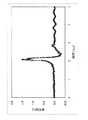
光ファイバー端で0.45J/パルス、気泡の中心からの距離5mmのとき、1.5MPa(
約11000mmHg)以上のピーク音圧が得られた、図5に0.45J/パルス、気泡の中心からの距離5mmのときの音圧波形を示す。血液中での音圧は粘性の影響で水中の3割程度になることが分かった。実施例1から、Ho:YAGレーザ誘起音圧波は平滑筋細胞に制御性のよい傷害を与えることが判明した。
【0036】
〔実施例2〕 レーザ誘起音圧波による平滑筋細胞の傷害
図6に示すようにように、増殖型平滑筋細胞(マウス由来大動脈平滑筋細胞P53LMACO1)を96ウェルプレート培養し、音圧波をピーク音圧(約1.20、1.26、1.46MPa)および回数(1O、20、160回)を変えて印加した。音圧波発生に用いたレーザ光発生装置、レーザ照射条件は実施例1と同じであった。音圧波印加48時間後にMTTアッセイにより、死細胞率を測定した。約1.20Mpa、1O回のとき約4%、1.46Mpa、20回のとき約42%の死細胞率となり、レーザ照射条件によって平滑筋細胞に制御性のよい傷害を与えることができた(図7)。
【0037】
〔実施例3〕 ウサギを用いた再狭窄予防治療
全麻酔下においた日本白色種家兎の大腿動脈より2Fr.バルーンカテーテルを挿入し大動脈を擦過傷害した再狭窄モデルを作成した。光ファイバーを大腿動脈に留置した4Fr.シースより、逆行性に挿入し大動脈でレーザ照射した。図8に、本実施例で用いたシステムを示す。6週間後に犠牲死させ、血管組織標本をHematoxilin−Eosin(HE)染色により作成し、治療効果を評価した。
【0038】
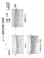
図9に結果を示す。図9は、図上に示すように、血管の一部を切断し展開した血管壁の断面を示し、図上部が内膜側であり下部が外膜側である。また、図中の矢印は内弾性板を示し、平滑筋細胞は該内弾性板より内膜側で増殖する。それぞれの写真は左上から時計回りに、正常(normal)血管、狭窄モデル血管ならびに0.06J/パルスのレーザ光を20回照射したものを示す。
【0039】
図に示すように、何ら処理を施していないNormalに対して、狭窄モデルでは内膜が厚くなっており平滑筋細胞の増殖が認められる。0.06J/パルスのレーザ光を20回照射したものでは、増殖が抑制されていた。この結果は、小さい照射エネルギーで平滑筋細胞の増殖を抑制することができることを示す。
【0040】
【発明の効果】
実施例に示すように、高強度パルス光を液体内で照射することにより水蒸気泡を発生させ、気泡が収縮・消滅するときに発生する音圧波で平滑筋細胞の増殖を阻害することができる。本発明の装置により、血管形成術を行った血管部位で高強度パルス光を照射し、音圧波を発生させることにより該音圧波で、血管形成部に遊走し定着する平滑筋細胞の増殖を阻害し、血管再狭窄を予防することができる。
【図面の簡単な説明】
【図1】本発明の装置を示した図である。
【図2】レーザ光照射により発生する水蒸気の発生から消滅までの過程を表す図を示す。
【図3】本発明の装置による再狭窄予防治療の概念図を示す。
【図4】照射レーザの強度(J/パルス)、気泡の中心からの距離(mm)とピーク音圧(MPa)との関係を示す図である。
【図5】レーザ強度0.45J/パルスを用いた場合の気泡の中心からの距離5mmの点での音圧波形を示す。
【図6】レーザ誘起音圧波による平滑筋細胞の傷害実験の方法を示す図である。
【図7】レーザ誘起音圧波による平滑筋細胞の傷害実験の結果を示す図である。
【図8】ウサギを用いた再狭窄予防治療の方法を示す図である。
【図9】ウサギを用いた再狭窄予防治療の結果を示す図である。[0001]
TECHNICAL FIELD OF THE INVENTION
The present invention relates to an apparatus for preventing restenosis of a stenotic blood vessel after percutaneous coronary angioplasty by a sound pressure wave induced by high-intensity pulsed light irradiation.
[0002]
[Prior art]
2. Description of the Related Art Conventionally, percutaneous coronary angioplasty (PTCA) has been widely performed on patients with angina or myocardial infarction using balloon dilatation with a balloon catheter. However, in vasodilation using a balloon catheter, the restenosis rate after three months was as high as 30 to 40%. In addition, percutaneous coronary angioplasty by stent placement is also performed. According to this method, although the restenosis rate is reduced to 15 to 35%, there is a problem of in-stent restenosis. If so, subsequent retreatment was difficult. In restenosis, the blood vessel wall is damaged by the forced expansion of the blood vessel lumen by a balloon, and during the subsequent healing process, smooth muscle cells migrate and proliferate from the vascular media to the damaged area of the intima, or hematopoietic stem cells adhere. It has been reported that they adhere to injured blood vessels via factors, differentiate and proliferate into smooth muscle cells, and cause hyperplasia of the intima.
[0003]
In contrast, an intravascular irradiation treatment method (Brachytherapy, Japanese Patent Application Laid-Open No. 9-508038, which discloses a method of irradiating a lesion site with an appropriate dose of radiation after balloon inflation to suppress cell proliferation in the healing process). Japanese Unexamined Patent Publication No. 2001-46532) has been developed.
[0004]
However, although radiation therapy is considered to be suitable for preventing restenosis in terms of inhibiting smooth muscle cell proliferation, it requires the use of equipment to deal with the side effects of damage to the blood vessel wall and surrounding tissues and radiation. There was a problem of sex.
[0005]
Also, a method using ultrasonic waves (sonotherapy) has been attempted. For example, treating smooth muscle cells with one or more anti-cytoskeletal agents, such as cytochalasin B or cortisin, and irradiating an effective amount of ultrasonic energy to reduce migration, survival or adhesion of the smooth muscle cells. Although a method for suppressing restenosis has been developed (Japanese Patent Application Laid-Open No. 2002-502804), there is a drawback that administration of an anticytoskeleton agent is essential. Furthermore, a photodynamic therapy for suppressing neointimal hyperplasia has also been attempted (WO 00/59505), but it is necessary to administer a PDT drug to a patient in advance, and the time required for the treatment is also shorter for the patient. The burden was heavy. Further, a method of preventing restenosis using a dispatch catheter having a drug administration means has been reported.
[0006]
In these restenosis prevention methods, catheters are used, but a radiation source is provided at the tip of the catheter, heat generating means is provided in the catheter, or a vibration source or a drug for generating ultrasonic waves in the catheter is used. It is necessary to provide a means for local administration of, so that the catheter becomes thick and difficult to handle.
[0007]
[Patent Document 1]
JP-A-7-289557
[Patent Document 2]
Japanese Patent Publication No. 9-508038
[Patent Document 3]
JP 2001-46532 A
[Patent Document 4]
Japanese Unexamined Patent Publication No. 2002-502804
[Patent Document 5]
WO00 / 59505
[0008]
[Problems to be solved by the invention]
An object of the present invention is to provide a device for preventing and treating restenosis, which overcomes the above-mentioned disadvantages of the prior art. That is, the present invention irradiates the blood vessel with high-intensity pulsed light by the high-intensity pulsed light irradiating means, generates steam bubbles in the blood vessels, and generates a sound pressure wave generated when the bubbles contract and disappear, thereby causing restenosis. A device that reduces smooth muscle cells that proliferate at the site of vascular injury and can inhibit the adhesion of hematopoietic stem cells.It can be used in the bloodstream without closing the bloodstream, and can be inserted into blood vessels. It is an object of the present invention to provide a device with low invasiveness characterized by having a small diameter.
[0009]
[Means for Solving the Problems]
As described above, restenosis damages the blood vessel wall due to forced expansion of the blood vessel lumen by the balloon, and in the subsequent healing process, smooth muscle cells migrate and proliferate from the vascular media to the damaged site of the intima, or Hematopoietic stem cells adhere to injured blood vessels via adhesion factors, differentiate and proliferate into smooth muscle cells, and cause intimal hyperplasia. The present inventors have intensively studied whether it is possible to suppress the proliferation of smooth muscle cells and further inhibit the adhesion of hematopoietic stem cells to prevent restenosis. The present inventors have focused on the phenomenon that when a laser beam is irradiated in a liquid, a steam bubble is generated, and a sound pressure wave is generated when the bubble is contracted and disappeared. Providing an irradiation site, irradiating high-intensity pulsed light such as laser in a blood vessel, generating a sound pressure wave, suppressing the proliferation of smooth muscle cells and adhesion of hematopoietic stem cells by the sound pressure wave, and finding that restenosis can be prevented, The present invention has been completed. The present invention is a device that requires a means for irradiating high-intensity pulsed light having a constant intensity and wavelength in a blood vessel, and basically generates a high-intensity pulsed light, and transmits the high-intensity pulsed light. Only the fiber for the transfer and the means for transporting the fiber to the treatment site in the blood vessel are sufficient, and the maximum diameter portion to be inserted into the blood vessel needs to be extremely small. For this reason, for example, when performing an operation on the coronary artery, it is not necessary to insert the blood vessel from a large blood vessel such as a femoral artery remote from the coronary artery as in the related art, and it is also possible to insert the blood vessel from a blood vessel with a thin arm close to the coronary artery. .
[0010]
That is, the present invention is as follows.
[1] A device for preventing and treating vascular restenosis, which reduces smooth muscle cells proliferating in a treated part after performing angioplasty by vasodilation by a sound pressure wave induced by high intensity pulsed light irradiation, wherein the sound pressure wave is generated in a blood vessel. Including a high-intensity pulsed light irradiation means capable of inducing a blood vessel restenosis prevention / treatment device,
[2] The apparatus for preventing or treating vascular restenosis according to [1], wherein the high-intensity pulsed light irradiating means can be inserted into a penetration lumen of a balloon catheter capable of performing percutaneous blood vessel formation by balloon expansion.
[3] The apparatus for preventing and treating vascular restenosis according to [1], further comprising a catheter, and a fiber for transmitting high-intensity pulsed light, disposed in the catheter.
[4] The device for preventing or treating vascular restenosis according to [3], wherein the catheter is a balloon catheter capable of performing percutaneous angioplasty by balloon dilation.
[5] At the wavelength of the high intensity pulsed light, the water absorption coefficient is 10 to 1000 cm-1 The device for preventing or treating vascular restenosis according to any one of [1] to [4], wherein
[6] The apparatus for preventing or treating vascular restenosis according to any one of [1] to [5], wherein the wavelength of the high-intensity pulsed light is in a range of 0.3 to 3 μm.
[7] The apparatus for preventing or treating vascular restenosis according to any one of [1] to [6], wherein the wavelength of the high-intensity pulsed light is in the range of 1.5 to 2.5 μm.
[8] The apparatus for preventing or treating vascular restenosis according to any one of [1] to [7], wherein the high-intensity pulsed light is a pulsed laser.
[9] The apparatus for preventing or treating vascular restenosis according to any one of [1] to [8], wherein the high-intensity pulsed light is pulsed light generated by an optical parametric oscillator (OPO).
[10] The apparatus for preventing and treating vascular restenosis according to [9], wherein the laser is a solid-state laser using rare earth ions,
[11] The apparatus for preventing or treating vascular restenosis according to [10], wherein the laser medium is Ho or Tm, and the laser base material is selected from the group consisting of YAG, YSGG and YVO.
[12] The apparatus for preventing or treating vascular restenosis according to [11], wherein the laser is a Ho: YAG laser or a Tm: YAG laser, and
[13] The device for preventing or treating vascular restenosis according to any one of [2] to [12], wherein the diameter of the catheter sheath portion inserted into the blood vessel is 2 mm or less.
Hereinafter, the present invention will be described in detail.
[0011]
BEST MODE FOR CARRYING OUT THE INVENTION
The present invention is an apparatus for preventing and treating restenosis using high-intensity pulsed light.
The device of the present invention includes at least high-intensity pulsed light irradiating means for irradiating high-intensity pulsed light into a blood vessel, and further includes a catheter for guiding the high-intensity pulsed light irradiation portion to a percutaneous coronary angioplasty site. May be included. FIG. 1 shows the schematic diagram of the device of the present invention.
[0012]
The high-intensity pulsed light irradiating means includes a high-intensity pulsed light generating means (high-intensity pulsed light source), a means for transmitting the high-intensity pulsed light into the blood vessel, a means for irradiating the high-intensity pulsed light into the blood vessel, and the like. The portion transmitting the intensity pulse light is an optical transmission fiber. The optical transmission fiber of the present invention may be inserted into a penetrating lumen in a catheter used for percutaneous angioplasty (PTCA) by balloon dilation so that high-intensity pulsed light reaches a treatment site. In this case, the treatment by the treatment device of the present invention is performed immediately after percutaneous angioplasty by balloon dilatation. In addition, a high intensity pulsed light transmitting optical fiber is arranged in advance in the balloon catheter used for the percutaneous angioplasty, and the balloon is deflated after the percutaneous angioplasty is performed and the high intensity pulsed light is irradiated. The treatment of the present invention may be performed. Accordingly, the present invention provides a sound pressure wave induced by high-intensity pulsed light irradiation to reduce the number of smooth muscle cells proliferating in a surgical site after performing angioplasty by vasodilation, thereby preventing sound restenosis in a blood vessel. The present invention also includes a vascular dilatation balloon catheter including high-intensity pulsed light irradiation means capable of inducing a pressure wave. Further, the present invention may be a dedicated device for preventing and treating vascular restenosis, which is disposed as a fiber for transmitting high-intensity pulsed light in a catheter. In this case, after angioplasty is performed using a vascular dilatation balloon catheter, the vascular dilation balloon catheter is removed from the body, and then vascular restenosis prevention treatment is performed. In the case of a dedicated device, it can also be used for prevention of restenosis after angioplasty by performing stent placement (for example, self-expandable stent). The means for irradiating the blood vessel with the high-intensity pulsed light is provided as a high-intensity pulsed light irradiator at the distal end of the optical transmission fiber. The high-intensity pulsed light irradiator may be provided with a member such as a prism for changing the pulsed light irradiating angle, but usually no special member is required and the distal end of the optical fiber is irradiated with the high-intensity pulsed light. Can act as a part.
[0013]
In the present invention, a sound pressure wave refers to a wave accompanied by pressure fluctuation in a medium. The sound pressure wave is also referred to as an acoustic wave, but in the present invention, the generated acoustic wave may be a shock wave due to the nonlinearity of the medium, and thus is generally referred to as a sound pressure wave. In the present invention, the sound pressure wave includes a sound wave having an audio frequency, an ultrasonic wave higher than the audio frequency, and an extremely low frequency lower than the audio frequency.
[0014]
The vascular catheter optionally included in the device of the present invention is a tube for inserting a part of the device of the present invention into a blood vessel, and is used as a guide when moving a part of the device to a target site. As the catheter, those commonly used can be used, and the diameter and the like are not limited, and can be appropriately designed according to the thickness of the blood vessel to be treated. The device of the present invention requires only one optical fiber for transmitting high-intensity pulsed light in the catheter, so that the diameter of the catheter can be reduced. For example, the diameter of the catheter sheath portion is 2 mm or less.
[0015]
The high-intensity pulsed light includes a pulsed light generated by a laser and an optical parametric oscillator (OPO: Optical Parametric Oscillator).
[0016]
As the laser generating means, a normal laser generating device can be used, and the laser type has an absorption coefficient of water of 10 to 1000 cm.-1 , Preferably 10-100 cm-1 The laser is not limited as long as it has a certain wavelength band, and a solid-state laser using rare earth ions, a XeCl excimer laser, or the like can be used. The oscillation wavelength of the laser is 0.3 to 3 μm, preferably 1.5 to 3 μm, more preferably 1.5 to 2.5 μm, and more preferably a wavelength near the absorption maximum of water (1.9 μm). is there. The laser is represented by ions of an element generating the laser and a type of a base material holding the ions. Ho (holonium), Tm (thulium), Er (erbium), and Nd (neodymium) belonging to rare earths as elements. And Ho and Tm are preferred. Examples of the base material include YAG, YSGG, YVO, and the like. For example, Ho: YAG laser, Tm: YAG laser, Ho: YSGG laser, Tm: YSGG laser, Ho: YVO laser, Tm: YVO laser, and XeCl excimer laser (oscillation wavelength: 308 nm) can be used. Among these, Ho: YAG laser (oscillation wavelength 2.1 μm), Tm: YAG laser (oscillation wavelength 2.01 μm), and the like, in which the oscillation wavelength of the laser is near the absorption maximum of water (1.9 μm), are preferable.
[0017]
As the laser generator, for example, LASER1-2-3 SCHWARTZ (manufactured by ELECTRO-OPTICS) and the like can be mentioned.
[0018]
An optical parametric oscillator (OPO; Optical Parametric Oscillator) is capable of continuously changing the wavelength of pulsed light and has an absorption coefficient of water of 10 to 1000 cm.-1 What is necessary is just to select the pulsed light of the wavelength band. For example, a wavelength around 0.3 to 3 μm, preferably 1.5 to 3 μm, more preferably 1.5 to 2.5 μm, and even more preferably near the absorption maximum of water (1.9 μm) may be selected.
[0019]
Means for transmitting high-intensity pulsed light into a blood vessel include means for irradiating high-intensity pulsed light (high-intensity pulsed light irradiator) located near the distal end of the catheter and high-intensity pulsed light for high-intensity pulsed light. A quartz fiber (optical fiber) (fiber for transmitting high intensity pulsed light) transmitted from the light generating device to the high intensity pulsed light irradiation means is included. As used herein, “near the distal end” means a portion near the end opposite to the end (proximal end) connected to the high-intensity pulsed light generator, and includes the distal end and the distal end. Refers to a portion of about several tens cm from the distal end.
[0020]
The quartz fiber is connected at one end to a high intensity pulsed light generator and at the other end to a high intensity pulsed light irradiator (high intensity pulsed light irradiator). The quartz fiber used in the present invention, from a very thin one having a diameter of about 0.05 to 0.3 mm to one having a visible thickness, can be directly inserted into a blood vessel or housed in a catheter. As long as it can be inserted into a blood vessel and transmit high-intensity pulsed light energy, a wide variety of diameters can be used.
[0021]
The high-intensity pulsed light irradiating means is a means for irradiating the blood vessel with the high-intensity pulsed light. The high-intensity pulsed light is generated by an extracorporeal high-intensity pulsed light generator (high-intensity pulsed light source). High-intensity pulsed light transmitted along the blood vessel in the blood vessel is irradiated into the blood vessel so that water vapor bubbles are formed in the blood. At this time, the direction of high-intensity pulsed light irradiation is not limited. Further, as described above, a plurality of high-intensity pulsed light transmission fibers may be dispersedly present. The diameter of the fibers is preferably between 100 μm and 1000 μm.
[0022]
The distal end of the optical fiber for transmitting high-intensity pulsed light, that is, the high-intensity pulsed light irradiating section at the tip of the optical fiber is retracted into the catheter rather than the tip of the catheter in order to avoid injury to the blood vessel wall due to the tip. It is desirable.
[0023]
The pulse width of the high-intensity pulsed light is not limited, but is 10 ns to 1 ms, preferably 100 μs to 400 μs. Note that the pulse width is indicated by the full width at half maximum.
The repetition frequency of the high intensity pulsed light is not limited.
[0024]
By irradiating the blood vessel with the high-intensity pulsed light, the energy density increases in front of the irradiated portion of the high-intensity pulsed light, a steam bubble is generated in that region, and a sound pressure wave is generated when the bubble contracts and disappears. It occurs and propagates from the point of occurrence. FIG. 2 is a diagram showing a process from generation to disappearance of water vapor generated by laser beam irradiation. FIG. 3 shows a conceptual diagram of restenosis prevention treatment using the device of the present invention.
[0025]
The sound pressure of the sound pressure wave is 0.1 to 100 MPa, preferably 1 to 50 MPa, more preferably 2 to 20 MPa at the blood vessel wall. The sound pressure of the sound pressure wave can be appropriately adjusted by changing the wavelength, pulse width, and energy of the high intensity pulse light.
[0026]
If high-intensity pulsed light is directly applied to the blood, red blood cell destruction occurs in that part. Therefore, it is desirable to replace the blood in that part with physiological saline or the like. As such a liquid, an infusion such as a dialysate is used in addition to physiological saline. In this case, a liquid sending means is incorporated in the catheter of the treatment apparatus of the present invention, and a portion of the blood vessel irradiated with high-intensity pulsed light, such as a saline solution, using the liquid sending means, ie, high-intensity pulsed light irradiation What is necessary is just to inject | pour in the vicinity of the irradiation part of a part. The liquid feeding means includes a liquid feeding channel provided in the catheter, an inlet provided at a distal end of the liquid feeding channel, a liquid reservoir connected to the channel, a pump for liquid feeding, and the like. As the liquid sending flow path, for example, a lumen may be provided in the catheter, and the lumen may be used as the liquid sending flow path, or a separate flow tube may be provided in the catheter. In this case, high-intensity pulsed light of the high-intensity pulsed light irradiating means is applied to the inside of the blood vessel in order to replace a local blood portion where a high-intensity pulsed light is irradiated into the blood vessel and a vapor bubble starts to be generated with physiological saline or the like. The part to be filled and the injection port of the liquid sending means must be located at positions close to each other. For example, a lumen may be provided in the catheter, a high-intensity pulsed light transmitting fiber may be passed through the lumen, and a physiological saline solution or the like may be sent through the lumen. The amount of physiological saline or the like to be sent is not limited, but an amount of about 1/10 to 1/1000 of the amount of liquid sent when using an endoscope for injecting a flush liquid and observing the lumen of a blood vessel is sufficient. . For example, in the method of injecting a flush liquid when observing the lumen of a blood vessel with an endoscope, it is necessary to inject a flush liquid of 1 to 2 mL / sec, but the injection amount in the present invention is about 1 mL / min. Is enough. With this level of liquid transfer, peripheral oxygen supply can be ensured without obstructing blood flow.
[0027]
The high-intensity pulsed light irradiation is desirably synchronized with the pulsation of the blood flow, that is, the pulsating blood flow. The blood flow is a pulsatile flow. When the blood flow is flowing, that is, when the kinetic energy (dynamic pressure) of the blood flow is large, the generation of water vapor bubbles affects the dynamic pressure in addition to the blood pressure (static pressure). box office. On the other hand, when the blood flow is completely stopped, since blood is a non-Newtonian fluid, the viscosity increases, and the generation of water vapor bubbles also becomes difficult. Therefore, there is an optimal timing when the pulsatile blood flow velocity has decreased (before the blood flow stops). In this case, the timing can be detected by setting a delay time unique to the observed blood vessel in the heartbeat information from the electrocardiogram. In this case, the electrocardiograph and the laser generator are electronically connected, and the electrocardiogram signal is passed through the delay generator to the high-intensity pulse light generator so that the high-intensity pulse light is emitted when the pulsatile blood flow decreases. You just have to communicate. The amount of time delay can be determined as appropriate by a combination of an electrocardiograph, a delay generator, and a high-intensity pulsed light generator. A person skilled in the art can also easily determine the timing of transmitting a signal such that high intensity pulsed light is emitted when the pulsatile blood flow is reduced from the electrocardiograph, from the relationship among the known cardiac cycle, aortic blood flow velocity, and electrocardiogram. For example, in the case of the coronary artery, almost no blood flows during systole when the aortic blood flow rate is large, and blood flows during diastole when the aortic blood flow rate is small. Therefore, the blood flow velocity in the coronary artery becomes maximum between the appearance of the P wave after the appearance of the T wave in the electrocardiogram, and the irradiation timing of the high intensity pulsed light is desirably from the appearance of the P wave to the disappearance of the QRS wave. Further, a pressure sensor or the like is provided on the catheter of the treatment device of the present invention, and the pulsation of blood flow is monitored by the sensor, so that high-intensity pulsed light is emitted when the pulsatile blood flow decreases. You may. Also in this case, the pressure sensor and the high intensity pulsed light generator are electronically connected, and a signal from the pressure sensor is provided to the high intensity pulsed light generator with a delay.
[0028]
Method of using the device of the present invention
The device of the present invention is a device for preventing restenosis of blood vessels after percutaneous angioplasty, and guides the high-intensity pulsed light irradiating part of the present invention to the percutaneous angioplasty site. The blood vessel targeted by the device of the present invention is not limited, and can be applied to any coronary artery and other blood vessels smaller than the coronary artery. The iliac artery, the superficial femoral artery, and the infra-knee artery, and the device of the present invention can also be suitably used for treatment of these arteries after angioplasty. At this time, when angioplasty is performed by balloon dilation using a balloon catheter having a penetrating lumen, the treatment is performed by inserting the high-intensity pulsed light irradiation part of the device of the present invention into the penetrating lumen and transporting it to the treatment site. It can be performed. Further, when the device of the present invention is disposed in a dedicated catheter and is a dedicated device for preventing restenosis, the catheter of the device of the present invention is removed after the balloon catheter for performing angioplasty is removed. May be inserted into a blood vessel, and the high-intensity pulsed light irradiating section may reach the treatment site to perform treatment. Also, when angioplasty is performed by placing a stent, restenosis prevention treatment can be performed using a dedicated device for restenosis prevention. In the device of the present invention, the portion to be inserted into a blood vessel is sufficient if it is a small-diameter catheter including one optical fiber for transmitting high-intensity pulsed light, and is not a thin blood vessel such as a femoral artery but a thin artery such as a radial artery. It can also be inserted from a blood vessel.
[0029]
The high-intensity pulsed light irradiation section of the apparatus of the present invention may be guided to a percutaneous angioplasty treatment site, and the high-intensity pulsed light may be irradiated in whole blood without closing the blood flow. The high-intensity pulsed light irradiation generates water vapor bubbles at the irradiation end of whole blood, and generates sound pressure waves when the bubbles contract and disappear. The sound pressure wave propagates in whole blood, propagates to the blood vessel wall, and reduces smooth muscle cells in the media. At this time, a small amount of physiological saline or the like may be injected into the portion of the blood vessel to be irradiated with the high-intensity pulsed light, if necessary, as described above.
[0030]
In addition, in order to reduce smooth muscle cells and prevent restenosis after angioplasty, it is common to irradiate high-intensity pulsed light after actually performing angioplasty to generate a sound pressure wave. However, high-intensity pulsed light may be irradiated in advance at a site where angioplasty is to be performed before angioplasty, and a sound pressure wave may be generated. Even if a sound pressure wave is generated before angioplasty is performed, smooth muscle cells in that portion can be reduced, and migration and fixation of smooth muscle cells at the vascular injury site after angioplasty can be prevented.
[0031]
【Example】
The present invention will be specifically described by the following examples, but the present invention is not limited by these examples.
[0032]
[Example 1] Sound pressure measurement of sound pressure wave induced by laser irradiation
Using a Ho: YAG laser generator (LASER1-2-3SCHWARTZ (ELECTRO-OPTICS, USA)), irradiate a Ho: YAG laser (wavelength: 2.1 μm, pulse width: 250 μs, frequency: 2 Hz) in water or blood, The sound pressure was measured using a needle type hydrophone (Model No. NH7020, manufactured by Toray Techno Co., Ltd.) using the laser output and the distance from the end of the optical fiber as parameters.The optical fiber used had an outer diameter of 600 μm and a core diameter of 400 μm. Was.
[0033]
At this time, irradiation was performed at an intensity of 0.13 J / pulse, 0.27 J / pulse or 0.45 J / pulse, and the sound pressure was measured at 5 mm, 10 mm, and 15 mm from the center of the generated steam bubbles.
[0034]
FIG. 4 shows the relationship between the intensity (J / pulse) of the irradiation laser, the distance (mm) from the center of the bubble, and the peak sound pressure (MPa). As shown in the figure, the peak sound pressure of the generated sound pressure wave was determined mainly by the distance from the center of the bubble, and the sound pressure at a certain point was considered to be inversely proportional to the square of the distance from the center of the bubble.
[0035]
When the end of the optical fiber is 0.45 J / pulse and the distance from the center of the bubble is 5 mm, 1.5 MPa (
FIG. 5 shows a sound pressure waveform at 0.45 J / pulse and a distance of 5 mm from the center of the bubble at which a peak sound pressure of about 11000 mmHg or more was obtained. The sound pressure in blood was found to be about 30% in water due to the effect of viscosity. From Example 1, it was found that the Ho: YAG laser-induced sound pressure wave caused a well-controlled injury to smooth muscle cells.
[0036]
[Example 2] Injury of smooth muscle cells by laser-induced sound pressure wave
As shown in FIG. 6, proliferating smooth muscle cells (mouse-derived aortic smooth muscle cells P53LMACO1) were cultured in a 96-well plate, and the sound pressure waves were peaked at sound pressures (about 1.20, 1.26, 1.46 MPa). And the number of times (10, 20, 160 times) was applied. The laser light generator and laser irradiation conditions used for generating the sound pressure wave were the same as those in Example 1. 48 hours after application of the sound pressure wave, the dead cell rate was measured by the MTT assay. The cell death rate was about 1.20 Mpa, 10 times, about 4%, 1.46 Mpa, 20 times, about 42%, and it was possible to injure the smooth muscle cells with good control by laser irradiation conditions ( (FIG. 7).
[0037]
[Example 3] Preventive treatment for restenosis using rabbits
2 Fr. from the femoral artery of a Japanese white rabbit under total anesthesia. A restenosis model was created in which a balloon catheter was inserted and the aorta was abraded. An optical fiber was placed in the femoral artery. It was inserted retrograde from the sheath and irradiated with laser in the aorta. FIG. 8 shows a system used in this embodiment. After 6 weeks, the animals were sacrificed and vascular tissue specimens were prepared by Hematoxylin-Eosin (HE) staining to evaluate the therapeutic effect.
[0038]
FIG. 9 shows the results. FIG. 9 shows a cross section of a blood vessel wall obtained by cutting and expanding a part of a blood vessel as shown in the figure. The upper part of the figure is the intima side and the lower part is the adventitia side. The arrow in the figure indicates the inner elastic plate, and smooth muscle cells proliferate on the intimal side of the inner elastic plate. Each photograph shows a normal blood vessel, a stenosis model blood vessel, and a laser beam of 0.06 J / pulse irradiated 20 times clockwise from the upper left.
[0039]
As shown in the figure, in the stenosis model, the intima was thicker and the proliferation of smooth muscle cells was observed with respect to Normal without any treatment. In the case where the laser beam of 0.06 J / pulse was irradiated 20 times, the proliferation was suppressed. This result indicates that the proliferation of smooth muscle cells can be suppressed with a small irradiation energy.
[0040]
【The invention's effect】
As shown in the embodiment, by irradiating high-intensity pulsed light in the liquid, a steam bubble is generated, and the sound pressure wave generated when the bubble contracts and disappears can inhibit the proliferation of smooth muscle cells. The device of the present invention irradiates high-intensity pulsed light to a vascular site where angioplasty has been performed, and generates a sound pressure wave, thereby inhibiting the proliferation of smooth muscle cells which migrate and fix in the angioplasty by the sound pressure wave. In addition, vascular restenosis can be prevented.
[Brief description of the drawings]
FIG. 1 is a diagram showing an apparatus of the present invention.
FIG. 2 is a diagram illustrating a process from generation to disappearance of water vapor generated by laser light irradiation.
FIG. 3 shows a conceptual diagram of restenosis prevention treatment by the device of the present invention.
FIG. 4 is a diagram showing the relationship between the intensity (J / pulse) of the irradiation laser, the distance (mm) from the center of the bubble, and the peak sound pressure (MPa).
FIG. 5 shows a sound pressure waveform at a point at a distance of 5 mm from the center of a bubble when a laser intensity of 0.45 J / pulse is used.
FIG. 6 is a diagram showing a method of an experiment for damaging smooth muscle cells by a laser-induced sound pressure wave.
FIG. 7 is a diagram showing the results of an experiment on smooth muscle cell damage caused by laser-induced sound pressure waves.
FIG. 8 is a view showing a method for preventing and treating restenosis using rabbits.
FIG. 9 is a diagram showing the results of restenosis preventive treatment using rabbits.
Claims (13)
Translated fromJapanesePriority Applications (1)
| Application Number | Priority Date | Filing Date | Title |
|---|---|---|---|
| JP2003157074AJP2004357792A (en) | 2003-06-02 | 2003-06-02 | Apparatus for preventing and treating vascular restenosis by sound pressure wave induced by high intensity pulsed light irradiation |
Applications Claiming Priority (1)
| Application Number | Priority Date | Filing Date | Title |
|---|---|---|---|
| JP2003157074AJP2004357792A (en) | 2003-06-02 | 2003-06-02 | Apparatus for preventing and treating vascular restenosis by sound pressure wave induced by high intensity pulsed light irradiation |
Publications (1)
| Publication Number | Publication Date |
|---|---|
| JP2004357792Atrue JP2004357792A (en) | 2004-12-24 |
Family
ID=34050964
Family Applications (1)
| Application Number | Title | Priority Date | Filing Date |
|---|---|---|---|
| JP2003157074APendingJP2004357792A (en) | 2003-06-02 | 2003-06-02 | Apparatus for preventing and treating vascular restenosis by sound pressure wave induced by high intensity pulsed light irradiation |
Country Status (1)
| Country | Link |
|---|---|
| JP (1) | JP2004357792A (en) |
Cited By (36)
| Publication number | Priority date | Publication date | Assignee | Title |
|---|---|---|---|---|
| WO2008088062A1 (en)* | 2007-01-17 | 2008-07-24 | Keio University | Vasodilator |
| JP2012508042A (en)* | 2008-11-05 | 2012-04-05 | ダニエル ホーキンス、 | Shock wave valve forming catheter system |
| KR101136906B1 (en) | 2009-09-29 | 2012-04-20 | 한국과학기술원 | Controller for smooth muscle contraction using pulsed laser and method for smooth muscle contraction using the same |
| JP2012085812A (en)* | 2010-10-19 | 2012-05-10 | Tohoku Univ | Optical fiber, and underwater shock wave generator using the same |
| US8709075B2 (en) | 2011-11-08 | 2014-04-29 | Shockwave Medical, Inc. | Shock wave valvuloplasty device with moveable shock wave generator |
| US9220521B2 (en) | 2012-08-06 | 2015-12-29 | Shockwave Medical, Inc. | Shockwave catheter |
| US9554815B2 (en) | 2012-08-08 | 2017-01-31 | Shockwave Medical, Inc. | Shockwave valvuloplasty with multiple balloons |
| US9579114B2 (en) | 2008-05-07 | 2017-02-28 | Northgate Technologies Inc. | Radially-firing electrohydraulic lithotripsy probe |
| US10039561B2 (en) | 2008-06-13 | 2018-08-07 | Shockwave Medical, Inc. | Shockwave balloon catheter system |
| US10357264B2 (en) | 2016-12-06 | 2019-07-23 | Shockwave Medical, Inc. | Shock wave balloon catheter with insertable electrodes |
| US10603058B2 (en) | 2013-03-11 | 2020-03-31 | Northgate Technologies, Inc. | Unfocused electrohydraulic lithotripter |
| US10646240B2 (en) | 2016-10-06 | 2020-05-12 | Shockwave Medical, Inc. | Aortic leaflet repair using shock wave applicators |
| US10702293B2 (en) | 2008-06-13 | 2020-07-07 | Shockwave Medical, Inc. | Two-stage method for treating calcified lesions within the wall of a blood vessel |
| US10966737B2 (en) | 2017-06-19 | 2021-04-06 | Shockwave Medical, Inc. | Device and method for generating forward directed shock waves |
| US11478261B2 (en) | 2019-09-24 | 2022-10-25 | Shockwave Medical, Inc. | System for treating thrombus in body lumens |
| US11596423B2 (en) | 2018-06-21 | 2023-03-07 | Shockwave Medical, Inc. | System for treating occlusions in body lumens |
| US11992232B2 (en) | 2020-10-27 | 2024-05-28 | Shockwave Medical, Inc. | System for treating thrombus in body lumens |
| US12011185B2 (en) | 2021-10-19 | 2024-06-18 | Shockwave Medical, Inc. | Intravascular lithotripsy catheter with interfering shock waves |
| US12023098B2 (en) | 2021-10-05 | 2024-07-02 | Shockwave Medical, Inc. | Lesion crossing shock wave catheter |
| US12035932B1 (en) | 2023-04-21 | 2024-07-16 | Shockwave Medical, Inc. | Intravascular lithotripsy catheter with slotted emitter bands |
| US12064129B2 (en) | 2015-11-18 | 2024-08-20 | Shockwave Medical, Inc. | Shock wave electrodes |
| US12089861B2 (en) | 2021-08-05 | 2024-09-17 | Nextern Innovation, Llc | Intravascular lithotripsy system and device |
| US12096950B2 (en) | 2012-09-13 | 2024-09-24 | Shockwave Medical, Inc. | Shockwave catheter system with energy control |
| US12114923B2 (en) | 2012-06-27 | 2024-10-15 | Shockwave Medical, Inc. | Shock wave balloon catheter with multiple shock wave sources |
| US12178458B1 (en) | 2024-05-16 | 2024-12-31 | Shockwave Medical, Inc. | Guidewireless shock wave catheters |
| US12193691B2 (en) | 2012-09-13 | 2025-01-14 | Shockwave Medical, Inc. | Shock wave catheter system with energy control |
| US12220141B2 (en) | 2023-06-29 | 2025-02-11 | Shockwave Medical, Inc. | Catheter system with independently controllable bubble and arc generation |
| US12226111B2 (en) | 2012-08-06 | 2025-02-18 | Shockwave Medical, Inc. | Low profile electrodes for an angioplasty shock wave catheter |
| US12232755B2 (en) | 2020-12-11 | 2025-02-25 | Shockwave Medical, Inc. | Lesion crossing shock wave catheter |
| US12232752B2 (en) | 2017-11-17 | 2025-02-25 | Shockwave Medical, Inc. | Low profile electrodes for a shock wave catheter |
| US12274460B2 (en) | 2019-09-24 | 2025-04-15 | Shockwave Medical, Inc. | Lesion crossing shock wave catheter |
| US12290268B2 (en) | 2023-03-31 | 2025-05-06 | Shockwave Medical, Inc. | Shockwave catheters for treating rhinosinusitis |
| US12402899B2 (en) | 2023-11-30 | 2025-09-02 | Shockwave Medical, Inc. | Systems, devices, and methods for generating shock waves in a forward direction |
| US12426938B2 (en) | 2019-09-24 | 2025-09-30 | Shockwave Medical, Inc. | Low profile electrodes for a shock wave catheter |
| US12426904B2 (en) | 2023-11-17 | 2025-09-30 | Shockwave Medical, Inc. | Intravascular lithotripsy catheter with oscillating impactor |
| US12433620B2 (en) | 2024-02-23 | 2025-10-07 | Shockwave Medical, Inc. | Locus emitter shock wave catheter devices with increased longevity and higher sonic output |
- 2003
- 2003-06-02JPJP2003157074Apatent/JP2004357792A/enactivePending
Cited By (62)
| Publication number | Priority date | Publication date | Assignee | Title |
|---|---|---|---|---|
| JP2008194455A (en)* | 2007-01-17 | 2008-08-28 | Keio Gijuku | Vasodilator |
| WO2008088062A1 (en)* | 2007-01-17 | 2008-07-24 | Keio University | Vasodilator |
| US11559318B2 (en) | 2008-05-07 | 2023-01-24 | Northgate Technologies Inc. | Radially-firing electrohydraulic lithotripsy probe |
| US9579114B2 (en) | 2008-05-07 | 2017-02-28 | Northgate Technologies Inc. | Radially-firing electrohydraulic lithotripsy probe |
| US11771449B2 (en) | 2008-06-13 | 2023-10-03 | Shockwave Medical, Inc. | Shockwave balloon catheter system |
| US10702293B2 (en) | 2008-06-13 | 2020-07-07 | Shockwave Medical, Inc. | Two-stage method for treating calcified lesions within the wall of a blood vessel |
| US10959743B2 (en) | 2008-06-13 | 2021-03-30 | Shockwave Medical, Inc. | Shockwave balloon catheter system |
| US10039561B2 (en) | 2008-06-13 | 2018-08-07 | Shockwave Medical, Inc. | Shockwave balloon catheter system |
| US10149690B2 (en) | 2008-11-05 | 2018-12-11 | Shockwave Medical, Inc. | Shockwave valvuloplasty catheter system |
| US9421025B2 (en) | 2008-11-05 | 2016-08-23 | Shockwave Medical, Inc. | Shockwave valvuloplasty catheter system |
| US12102342B2 (en) | 2008-11-05 | 2024-10-01 | Shockwave Medical, Inc. | Shockwave valvuloplasty catheter system |
| US9044619B2 (en) | 2008-11-05 | 2015-06-02 | Shockwave Medical, Inc. | Shockwave valvuloplasty catheter system |
| US11000299B2 (en) | 2008-11-05 | 2021-05-11 | Shockwave Medical, Inc. | Shockwave valvuloplasty catheter system |
| US9044618B2 (en) | 2008-11-05 | 2015-06-02 | Shockwave Medical, Inc. | Shockwave valvuloplasty catheter system |
| JP2012508042A (en)* | 2008-11-05 | 2012-04-05 | ダニエル ホーキンス、 | Shock wave valve forming catheter system |
| KR101136906B1 (en) | 2009-09-29 | 2012-04-20 | 한국과학기술원 | Controller for smooth muscle contraction using pulsed laser and method for smooth muscle contraction using the same |
| JP2012085812A (en)* | 2010-10-19 | 2012-05-10 | Tohoku Univ | Optical fiber, and underwater shock wave generator using the same |
| US10478202B2 (en) | 2011-11-08 | 2019-11-19 | Shockwave Medical, Inc. | Shock wave valvuloplasty device with moveable shock wave generator |
| US9289224B2 (en) | 2011-11-08 | 2016-03-22 | Shockwave Medical, Inc. | Shock wave valvuloplasty device with moveable shock wave generator |
| US8709075B2 (en) | 2011-11-08 | 2014-04-29 | Shockwave Medical, Inc. | Shock wave valvuloplasty device with moveable shock wave generator |
| US9814476B2 (en) | 2011-11-08 | 2017-11-14 | Shockwave Medical, Inc. | Shock wave valvuloplasty device with moveable shock wave generator |
| US12114923B2 (en) | 2012-06-27 | 2024-10-15 | Shockwave Medical, Inc. | Shock wave balloon catheter with multiple shock wave sources |
| US9220521B2 (en) | 2012-08-06 | 2015-12-29 | Shockwave Medical, Inc. | Shockwave catheter |
| US12226111B2 (en) | 2012-08-06 | 2025-02-18 | Shockwave Medical, Inc. | Low profile electrodes for an angioplasty shock wave catheter |
| US10758255B2 (en) | 2012-08-08 | 2020-09-01 | Shockwave Medical, Inc. | Shock wave valvuloplasty with multiple balloons |
| US12310605B2 (en) | 2012-08-08 | 2025-05-27 | Shockwave Medical, Inc. | Shock wave valvuloplasty with multiple balloons |
| US9554815B2 (en) | 2012-08-08 | 2017-01-31 | Shockwave Medical, Inc. | Shockwave valvuloplasty with multiple balloons |
| US11766271B2 (en) | 2012-08-08 | 2023-09-26 | Shockwave Medical, Inc. | Shock wave valvuloplasty with multiple balloons |
| US12193691B2 (en) | 2012-09-13 | 2025-01-14 | Shockwave Medical, Inc. | Shock wave catheter system with energy control |
| US12096950B2 (en) | 2012-09-13 | 2024-09-24 | Shockwave Medical, Inc. | Shockwave catheter system with energy control |
| US11559319B2 (en) | 2013-03-11 | 2023-01-24 | Northgate Technologies Inc. | Unfocused electrohydraulic lithotripter |
| US10603058B2 (en) | 2013-03-11 | 2020-03-31 | Northgate Technologies, Inc. | Unfocused electrohydraulic lithotripter |
| US12048445B2 (en) | 2013-03-11 | 2024-07-30 | Northgate Technologies, Inc. | Unfocused electrohydraulic lithotripter |
| US12245782B2 (en) | 2015-11-18 | 2025-03-11 | Shockwave Medical, Inc. | Shock wave electrodes |
| US12064129B2 (en) | 2015-11-18 | 2024-08-20 | Shockwave Medical, Inc. | Shock wave electrodes |
| US12144516B2 (en) | 2016-10-06 | 2024-11-19 | Shockwave Medical, Inc. | Aortic leaflet repair using shock wave applicators |
| US10646240B2 (en) | 2016-10-06 | 2020-05-12 | Shockwave Medical, Inc. | Aortic leaflet repair using shock wave applicators |
| US11517337B2 (en) | 2016-10-06 | 2022-12-06 | Shockwave Medical, Inc. | Aortic leaflet repair using shock wave applicators |
| US10357264B2 (en) | 2016-12-06 | 2019-07-23 | Shockwave Medical, Inc. | Shock wave balloon catheter with insertable electrodes |
| US10966737B2 (en) | 2017-06-19 | 2021-04-06 | Shockwave Medical, Inc. | Device and method for generating forward directed shock waves |
| US12232754B2 (en) | 2017-06-19 | 2025-02-25 | Shockwave Medical, Inc. | Device and method for generating forward directed shock waves |
| US11950793B2 (en) | 2017-06-19 | 2024-04-09 | Shockwave Medical, Inc. | Device and method for generating forward directed shock waves |
| US11602363B2 (en) | 2017-06-19 | 2023-03-14 | Shockwave Medical, Inc. | Device and method for generating forward directed shock waves |
| US12232752B2 (en) | 2017-11-17 | 2025-02-25 | Shockwave Medical, Inc. | Low profile electrodes for a shock wave catheter |
| US12114874B2 (en) | 2018-06-21 | 2024-10-15 | Shockwave Medical, Inc. | System for treating occlusions in body lumens |
| US11596423B2 (en) | 2018-06-21 | 2023-03-07 | Shockwave Medical, Inc. | System for treating occlusions in body lumens |
| US12274460B2 (en) | 2019-09-24 | 2025-04-15 | Shockwave Medical, Inc. | Lesion crossing shock wave catheter |
| US12426938B2 (en) | 2019-09-24 | 2025-09-30 | Shockwave Medical, Inc. | Low profile electrodes for a shock wave catheter |
| US12402897B2 (en) | 2019-09-24 | 2025-09-02 | Shockwave Medical, Inc. | System for treating thrombus in body lumens |
| US11478261B2 (en) | 2019-09-24 | 2022-10-25 | Shockwave Medical, Inc. | System for treating thrombus in body lumens |
| US11992232B2 (en) | 2020-10-27 | 2024-05-28 | Shockwave Medical, Inc. | System for treating thrombus in body lumens |
| US12232755B2 (en) | 2020-12-11 | 2025-02-25 | Shockwave Medical, Inc. | Lesion crossing shock wave catheter |
| US12089861B2 (en) | 2021-08-05 | 2024-09-17 | Nextern Innovation, Llc | Intravascular lithotripsy system and device |
| US12023098B2 (en) | 2021-10-05 | 2024-07-02 | Shockwave Medical, Inc. | Lesion crossing shock wave catheter |
| US12011185B2 (en) | 2021-10-19 | 2024-06-18 | Shockwave Medical, Inc. | Intravascular lithotripsy catheter with interfering shock waves |
| US12290268B2 (en) | 2023-03-31 | 2025-05-06 | Shockwave Medical, Inc. | Shockwave catheters for treating rhinosinusitis |
| US12035932B1 (en) | 2023-04-21 | 2024-07-16 | Shockwave Medical, Inc. | Intravascular lithotripsy catheter with slotted emitter bands |
| US12220141B2 (en) | 2023-06-29 | 2025-02-11 | Shockwave Medical, Inc. | Catheter system with independently controllable bubble and arc generation |
| US12426904B2 (en) | 2023-11-17 | 2025-09-30 | Shockwave Medical, Inc. | Intravascular lithotripsy catheter with oscillating impactor |
| US12402899B2 (en) | 2023-11-30 | 2025-09-02 | Shockwave Medical, Inc. | Systems, devices, and methods for generating shock waves in a forward direction |
| US12433620B2 (en) | 2024-02-23 | 2025-10-07 | Shockwave Medical, Inc. | Locus emitter shock wave catheter devices with increased longevity and higher sonic output |
| US12178458B1 (en) | 2024-05-16 | 2024-12-31 | Shockwave Medical, Inc. | Guidewireless shock wave catheters |
Similar Documents
| Publication | Publication Date | Title |
|---|---|---|
| JP2004357792A (en) | Apparatus for preventing and treating vascular restenosis by sound pressure wave induced by high intensity pulsed light irradiation | |
| US6210393B1 (en) | Methods and systems for the inhibition of vascular hyperplasia | |
| JP3955897B2 (en) | Ultrasonic therapy device | |
| US20070239082A1 (en) | Shock Wave Treatment Device | |
| US8162859B2 (en) | Shock wave treatment device and method of use | |
| JP4966640B2 (en) | Photodynamic therapy device and method of using the same | |
| EP4199849B1 (en) | Faster rise time pulse shaping of plasma generated pressure waves for disruption of vascular calcium | |
| US8097028B2 (en) | Photoreactive system and methods for prophylactic treatment of atherosclerosis | |
| CA2092537A1 (en) | Inhibition of restenosis of ultraviolet radiation | |
| Atar et al. | Perspectives on the role of ultrasonic devices in thrombolysis | |
| US6106546A (en) | Inducing vasodilation | |
| JP5265206B2 (en) | Vasodilator | |
| Isner et al. | Laser-induced dissections: pathogenesis and implications for therapy | |
| Zharov et al. | Laser combined medical technologies from Russia | |
| US20040158317A1 (en) | Coated stent with ultrasound therapy | |
| JP2006149974A (en) | Device for preventing and treating vascular restenosis by controlled sound pressure wave induced by high-intensity pulsed light irradiation | |
| Takekawa et al. | Laser Angioplasty-Fundamental Studies and Initial Clinical Experience | |
| Tachibana et al. | Ultrasound energy for enhancement of fibrinolysis and drug delivery: special emphasis on the use of a transducer-tipped ultrasound system | |
| JP4791616B2 (en) | Drug carrier and method of using the same | |
| Pai | Therapeutic Applications: Lasers in Vascular Surgery | |
| WO2004075977A2 (en) | Methods using diffuse field ultrasound-induced hyperthermia | |
| Suga et al. | Study for prevention of proliferation of smooth muscle cells after balloon angioplasty using Ho: YAG laser-induced acoustic wave | |
| WO2000059505A1 (en) | Inhibitors for vascular reconstriction after angioplasty | |
| JPH08245420A (en) | Treating tool using ultrasonic wave | |
| Visuri et al. | Optically generated ultrasound for enhanced drug delivery |
Legal Events
| Date | Code | Title | Description |
|---|---|---|---|
| A621 | Written request for application examination | Free format text:JAPANESE INTERMEDIATE CODE: A621 Effective date:20060511 | |
| A977 | Report on retrieval | Free format text:JAPANESE INTERMEDIATE CODE: A971007 Effective date:20080528 | |
| A131 | Notification of reasons for refusal | Free format text:JAPANESE INTERMEDIATE CODE: A131 Effective date:20080610 | |
| A521 | Written amendment | Free format text:JAPANESE INTERMEDIATE CODE: A523 Effective date:20080811 | |
| A131 | Notification of reasons for refusal | Free format text:JAPANESE INTERMEDIATE CODE: A131 Effective date:20080924 | |
| A02 | Decision of refusal | Free format text:JAPANESE INTERMEDIATE CODE: A02 Effective date:20090106 |