JP2004354792A - Display device for vehicle - Google Patents
Display device for vehicleDownload PDFInfo
- Publication number
- JP2004354792A JP2004354792AJP2003153646AJP2003153646AJP2004354792AJP 2004354792 AJP2004354792 AJP 2004354792AJP 2003153646 AJP2003153646 AJP 2003153646AJP 2003153646 AJP2003153646 AJP 2003153646AJP 2004354792 AJP2004354792 AJP 2004354792A
- Authority
- JP
- Japan
- Prior art keywords
- vehicle
- display device
- light
- display
- display screen
- Prior art date
- Legal status (The legal status is an assumption and is not a legal conclusion. Google has not performed a legal analysis and makes no representation as to the accuracy of the status listed.)
- Granted
Links
Images


Landscapes
- Instrument Panels (AREA)
- Liquid Crystal Display Device Control (AREA)
- Control Of Indicators Other Than Cathode Ray Tubes (AREA)
- Control Of El Displays (AREA)
- Liquid Crystal (AREA)
- Fittings On The Vehicle Exterior For Carrying Loads, And Devices For Holding Or Mounting Articles (AREA)
- Vehicle Waterproofing, Decoration, And Sanitation Devices (AREA)
- Devices For Indicating Variable Information By Combining Individual Elements (AREA)
Abstract
Description
Translated fromJapanese【0001】
【発明の属する技術分野】
本発明は、車両に用いる車両用表示装置に関する。
【0002】
【従来の技術】
車両の窓ガラスにレーザビームを照射することにより、この窓ガラスをスクリーンとして画像を表示する表示手段を備えた車両用表示装置がある(例えば特許文献1参照。)。
【0003】
【特許文献1】
特開2000−168352号公報
【0004】
【発明が解決しようとする課題】
本発明は、表示機能の高機能化、高付加価値化を実現した車両用表示装置を提供することを課題とする。
【0005】
【課題を解決するための手段】
本発明の車両用表示装置は、表示画面の前面から、窓ガラスを通して、車両外部を視認可能とした車両用表示装置であって、前記表示画面は透光性物質と、前記透光性物質に形成された一対の透光性電極とから形成され、前記表示画面は、一部または全面を表示面とすることができ、前記車両の外部環境に応じて、前記表示画面が変化し情報を表示することを特徴とする。
【0006】
本発明の車両用表示装置は、表示画面の前面から、窓ガラスを通して、車両外部を視認可能とした車両用表示装置であって、前記表示画面は透光性物質と、前記透光性物質に形成された一対の透光性電極とから形成され、前記表示画面は、一部または全面を表示面とすることができ、前記車両の外部環境を検出する外部環境検出手段を有し、前記外部環境検出手段により得られた情報を、前記表示画面が変化し表示することを特徴とする。
【0007】
本発明の車両用表示装置は、表示画面の前面から、窓ガラスを通して、車両外部を視認可能とした車両用表示装置であって、前記表示画面は透光性物質と、前記透光性物質に形成された一対の透光性電極とから形成され、前記表示画面は、一部または全面を表示面とすることができ、前記車両の位置情報、及び前記位置情報から得られる車両外部環境を検出する検出手段と、前記検出手段によって得られる情報を記憶する記憶手段とを有し、前記情報を前記表示画面に表示することを特徴とする。
【0008】
前記構造において、表示装置の前記表示画面は、非点灯時にその非点灯の表示部分から窓ガラスを通して、車両外部を視認可能としている。
【0009】
また、前記構造において、前記表示画面に入射する光の波長を変化させる手段を有してもよい。前記手段によって光のある波長を遮断または吸収し、光の一定の波長のみを透過させる。入射時と射出時において光の色は変えられ、車両用表示装置に入射する。具体的には透光性を有する色つきのセロハン紙やガラス、プラスチックなどに、光を通過させ、光の色を変化させる。また、透光性や半透光性を有する不活性ガスや液体、または樹脂材料などを用いてもよい。
【0010】
色を調節された光を車両用表示装置に入射することによって、画像は多種多様に変化する。様々な表示をすることが可能となるので、表示に対する利用者の選択の幅は広がる。よって、利用者は、自身の心理状態や体調に合った画像を選択することができる。利用者は画像からリラクゼーション効果などを得ることができ、快適な運転を楽しめる。また、天候や、照明などの変化によって光の強度や色は変化するので、車両用表示装置に入射する光の色や強度を調節することによって、画像の鮮明さ等を調節できる。
【0011】
表示素子は、一対の透光性物質の間に液晶物質などの光の透過率を変化させる物質を有するものでもよいし、自発光する発光物質を有するものでもよい。
【0012】
発光物質としては、有機化合物材料、無機化合物材料、またはそれらを組み合わせた物質などを広く用いることができる。発光物質のルミネッセンスには、一重項励起状態から基底状態に戻る際の発光(蛍光)と三重項励起状態から基底状態に戻る際の発光(リン光)がある。本発明に用いることのできる発光物質は、一重項励起もしくは三重項励起、もしくは両者の励起を経由して発光するすべての発光物質を含む。
【0013】
また、透光性物質としては、石英、ガラス(例えば、無アルカリガラス、強化ガラスもしくは耐熱ガラスなど)、プラスチック(例えば、PES(ポリエーテルサルフォン)、PET(ポリエチレンテレフタレート)PEN(ポリエチレンナフタレート)、もしくはPI(ポリイミド)など)などであり、その他可撓性を有するプラスチック基板を用いてもよい。可撓性を有する基板を用いた場合には、車両のフロントガラスのわん曲面にそって固着させることもできる。
【0014】
本発明の車両用表示装置では、画像を表示する表示機能を有し、かつ透光性であるという機能を有している。よって、利用者の視野を妨げることなく利用することができる。
【0015】
また、上記構造をもつ本発明の車両用表示装置を一対の偏光板で挟んだ構造でもよい。一対の偏光板の偏光の向きがそろっている場合、透光性を有する車両用表示装置として用いることができ、偏光板の偏光の向きを90度異ならせた場合は、車両用表示装置を光が通過することはできなくなり、表示画面は点灯時、非点灯時に関わらず、非透光性となる。透光性の度合いは偏光板同士の向きの異なりによる。
【0016】
また上記構成において、表示画面は、複数あってもよく、その大きさや形状はどのようなものでもよい。従って、設計の自由度が高くなる。なお、一般的に、表示素子が封止された状態をパネル、該パネルにコントローラ等のICを実装した状態をモジュールとよぶが、ここで表示装置はパネルやモジュールを総称した名称である。
【0017】
本発明の車両用表示装置は透光性を有するので、運転手の視界を妨げないため、車両の窓ガラス(フロントガラスやサイドの窓ガラス、リアウインドウガラス)部分に、重ねて設置することができる。また、運転者や同乗者が、外の風景を見ながら、必要な情報を得ることができるため、有益である。また車両にカメラやセンサを設置しておき、速度や周囲の情報を表示することが出来るので、運転者はより安全かつ快適に運転することができる。このように、本発明により、高機能、高付加価値を付与された車両用表示装置を提供することができる。
【0018】
【発明の実施の形態】
本発明の実施の形態を、図面を用いて詳細に説明する。
【0019】
(実施の形態1)
本発明の車両用表示装置を具備した車両の例を図1(a)及び(b)に示す。図1(a)に示すように車両用表示装置100は、一対の透光性電極104、105の間に発光媒体である発光性物質103が備えられ、それが透光性基板101、102に挟まれて構成されている。そして、透光性基板101と102のいずれか一方は、車両のフロントガラスなど透光性の構造体106に固着可能としている。透光性基板101、102としては、市販されている強化ガラスや、無アルカリガラス(例えば、アルミノシリケートガラス、バリウムホウケイガラス酸ガラスなど)、またはPET、PENなどのプラスチックなどを適用することができる。構造体106への固定の方法は、特に限定されず、接着剤を用いて固着してもよいし、粘着テープなどを用いて脱着可能としてもよい。また固定するための治具を用いて機械的に固定してもよい。
【0020】
この車両用表示装置100は、発光性物質103から放射される光が、矢印で示すように透光性基板101、102の両面から取り出すことができる構成となっている。放射される光は、車両用表示装置100の画面において文字、記号、図形などの画像を表示して利用者に情報を提供する。よって、車両の内部にいる利用者に向けて情報を提供したり、車両外部に向けて情報を表示したりすることができる。
【0021】
図1(b)は、本発明の車両用表示装置を乗用車などの車両のフロントガラスに設置した例を示す図面である。図1(a)において示す構成により、車両用表示装置100は透光性を有しているので、車両のフロントガラス106の任意の箇所に固定しても視界を妨げることなく利用することができる。
【0022】
車両用表示装置100の大きさは、透光性であることからフロントガラス106の全面を覆って配置することもできるが、典型的にはフロントガラス106の下方に帯状に配置してもよいし、車両の助手席側に適宜配置してもよい。また、車両用表示装置において、文字、記号、図形などを表示する領域は、表示画面の全面でもよいし、一部を表示領域としてその他の領域は非表示領域としておいてもよい。
【0023】
図1では、車両用表示装置100を車両のフロントガラスに設置する場合を示しているが、勿論、本発明はこれに限定されず、車両の側面の窓ガラスや後方の窓ガラス(リアウインドウガラス)あるいはサンルーフと呼ばれる車両の上方(天井)に設置される窓ガラスに適用してもよい。また、車両の種類も特に限定されず、さまざまな交通手段の車両に適用することができる。
【0024】
よって、本発明の車両用表示装置を用いると、利用者は、画像と車両の外部を同時に見ることが出来るので、表示される画像から情報を得ながら、車両外部を視認し、安全に運転をすることが可能であり便利である。
【0025】
(実施の形態2)
本発明の車両用表示装置を具備した車両の例を図2(a)、(b)、図11、図12(a)、(b)に示す。図2(a)に示すように車両用表示装置200は、一対の透光性電極の間に発光媒体である発光性物質が備えられ、それが透光性基板に挟まれて構成されている。車両用表示装置200は、間に空間222を有するように、フロントガラス207と一部固定されている。固定の方法は、特に限定されず、接着剤を用いて固着してもよいし、粘着テープなどを用いて脱着可能としてもよい。また固定するための治具を用いて機械的に固定してもよい。
【0026】
車両用表示装置200とフロントガラス207の間には空間222がある。空間222の下方には、ポンプ220を有している。ポンプ220は、排気管と吸気管で空間222に不活性ガスを送り込むことができる。また、ポンプ220は排気管221も有している。図示していないが、排気管221は車両外部へ通じており、排気を行う。不活性ガスを、半透光性の着色されたガスにすることによって、車外から入射した外光をある一定の波長の光に変えることができる。光の波長を制御することによって、車両用表示装置に入射する光の色や明るさを調整することができるので、表示画像を多種多様に変化させることができる。
【0027】
よって利用者は、表示画像を利用者の心理状態や体調に合うように調整することができる。利用者は表示画像からリラクゼーション効果などを得ることができ、快適な運転を楽しめる。
【0028】
この車両用表示装置200は、発光性物質から放射される光が、矢印で示すように透光性基板の両面から取り出すことができる構成となっている。放射される光は、車両用表示装置200の画面において文字、記号、図形などの画像を表示して利用者に情報を提供する。よって、車両の内部にいる利用者に向けて情報を提供したり、車両外部に向けて情報を表示したりすることができる。
【0029】
図2(b)は、本発明の車両用表示装置を乗用車などの車両のフロントガラスに設置した例を示す図面である。図2(a)において示す構成により、車両用表示装置200は透光性を有しているので、車両のフロントガラス207の任意の箇所に固定しても視界を妨げることなく利用することができる。よって利用者は、表示される画像から情報を得ながら、車両外部を視認し、安全に運転をすることが可能であり便利である。
【0030】
また、図12(a)に、表示素子として、透光性基板211と212の間に、光の透過率を変化させる物質215を挟んだ透光性電極213及び212を有する車両用表示装置210を用いた場合を示す。本実施の形態では、光の透過率を変更させる機能を有する物質として液晶を用いる。また、図12(a)の車両用表示装置を具備した車両を図12(b)に示す。
【0031】
液晶素子は、光の透過率を変化させ、画像を表示する素子であるから、光源が必要である。本実施の形態では、車両外部からの光(太陽光など)を、反射板217を用いて反射し、表示装置210に照射している。そうすることで、外部から入射光218を有効に表示装置210に照射させることができ、鮮明な画像を表示できる。反射板217は、光を反射できるものなら何でもよい。本実施の形態では、反射板217に鏡を用いる。
【0032】
よって運転者は、フロントガラスに表示される画像から情報を得ながらも、安全に運転をすることが可能であり便利である。また、本発明の車両用表示装置は薄型、軽量であり、車内のような狭いスペースでも十分に活用できる。
【0033】
次に、図2のように表示画像を多様に調整し、かつ図12のように反射板を用いる例を図11に示す。図11は入射光503をフィルター505を通過させた後、反射板504を用いて反射させる。反射光は再びフィルター505を通過し、車両用表示装置502に照射される。フィルター505は光の可視光領域のある波長を遮断もしくは吸収し、光の波長を変化させ、光の色を変える機能を有する透光性、または半透光性の物質を用いる。よってフィルター505を介すと、光は入射時と射出時で色が変化する。フィルター505は、円上の支持板507に備えられており、モーター506によって矢印の方向に回転する。支持板507にそれぞれ異なった波長を吸収するフィルターを備えていれば、反射板を回転させ多様な色の光を自由に車両用表示装置に照射することができる。
【0034】
反射板507を回転させるモーター506は利用者が操作することができるので、車両用表示装置に照射する光の色も自由に操作することができる。フィルター507にはガラスフィルター、干渉フィルターなどの光学フィルターや廉価版としては着色された有機樹脂フィルムなどを用いてもよい。また、図2のように透光性や半透光性を有する不活性ガスや液体、または樹脂物質などでもよい。
【0035】
一定の波長に調整された光を車両用表示装置に入射することによって、表示画像が多様化し、利用者の心理状態や体調に合った表示画像を選択することができる。利用者は画像からリラクゼーション効果などを得ることができ、快適な運転を楽しめる。また、天候や、照明などの変化によって光の強度や色は変化するので、車両用表示装置に入射する光を調整することによって、画像の鮮明さ等を調節できる。
【0036】
(実施の形態3)
本実施の形態では、本発明の車両用表示装置の詳しい構造について図3を用いて説明する。
【0037】
図3(a)に、トランジスタを用いたアクティブマトリクス型の車両用表示装置を示す。透光性基板920上にトランジスタ916を含み、トランジスタ916に接続して、第1の透光性電極911、発光物質を含む層913、第2の透光性電極914、透光性基板918からなる車両用表示装置915が構成される。車両用表示装置915に接して透光性を有する構造体917が設けられる。透光性を有する構造体917は車両の窓ガラスなどに相当する。
【0038】
図3(b)に、パッシブ型の車両用表示装置を示す。透光性基板922上に、第1の透光性電極923、発光物質を含む層926、第2の透光性電極927が設けられる。また、バンクとして機能する絶縁膜924、樹脂層925が設けられ、透光性基板929を設けて、車両用表示装置928が構成される。そして車両用表示装置928に接して、透光性を有する構造体921が設けられる。発光物質としては、有機材料、無機材料どちらを含んでいてもよい。なお、透光性電極の材料は、ITO等の透明導電膜や、光を透過できる厚さで形成されたアルミニウム等の導電膜を用いればよい。透光性を有する構造体921は車両の窓ガラスなどに相当する。
【0039】
図3(c)に、表示素子として、発光素子でなく、液晶素子を用いた車両用表示装置を示す。第1の透光性電極933、配向膜934を設けた透光性基板932と、第2の透光性電極、配向膜936を設けた透光性基板938とをシール等で張り合わせ、真空注入により液晶層935を設けて、車両用表示装置939が構成される。そして車両用表示装置939に接して透光性を有する構造体931が設けられる。透光性を有する構造体931は車両の窓ガラスなどに相当する。
【0040】
本発明の車両用表示装置は透光性を有しているので、車両の窓ガラス等の任意の箇所に固定しても視界を妨げることなく利用することができる。よって利用者は、表示される画像から情報を得ながら、車両外部を視認し、安全に運転をすることが可能であり便利である。
【0041】
続いて、上記とは異なり、イメージセンサ機能も有する場合の車両用表示装置について図9を用いて説明する。
【0042】
図9において、透光性を有する構造体917、透光性基板920上にトランジスタ917、第1の透光性電極911、発光物質を含む層913及び第2の透光性電極914が設けられており、ここまでは図3(A)の示す構成と同じである。本構成では、第2の透光性電極914上に形成された絶縁膜958上に、P型層952、I型(真性)層953及びN型層954の積層体からなる光電変換素子956と、P型層952に接続された電極951、N型層954に接続された電極955が設けられる。
【0043】
上記構成を有する車両用表示装置は、光源として第1の透光性電極911、発光物質を含む層913及び第2の透光性電極914からなる発光素子960、イメージセンサ素子として光電変換素子956を用いる。発光素子960及び光電変換素子956は同一の基板920上に配置されており、発光素子960から発せられる光は、被写体957において反射し、その反射した光は光電変換素子960に入射する。そうすると、光電変換素子960の両電極間の電位差は変化し、その変化した電位差に応じて両電極間に電流が流れ、その流れた電流量を検知することで、被写体957の情報を得ることができる。そして、その得られた情報は、発光素子960を用いて表示することができる。
【0044】
つまり、発光素子960は、被写体の情報を読み取る際の光源としての役割と、画像を表示する役割の2つの役割を果たす。そして、本実施の形態における車両用表示装置は、透光性を有する物体としての機能と画像を表示する表示機能に加えて、被写体の情報を読み取るイメージセンサ機能の合わせて3つの機能を有する。このように、3つの機能を有しているにも関わらず、イメージセンサ機能を用いる際には通常必要である光源や光散乱板を別個に設ける必要がないため、本実施の形態における車両用表示装置を用いると、大幅な薄型化及び軽量化が実現する。
【0045】
なお、図9では、発光素子と光電変換素子とを同一基板上に形成する場合を図示したが、図3(B)に図示したパッシブ型の発光素子と光電変換素子とを同一基板上に形成してもよい。また、一画素に発光素子960及び光電変換素子956を有する場合を図示したが、画素毎に光電変換素子956を設ける必要はなく、読み取る被写体やその用途に従って、複数の画素毎に光電変換素子956を設けてもよい。そうすると、発光素子960の開口率が拡大し、表示機能を用いる場合に明るい画像を提供することができる。
【0046】
なお、図3を用いて説明した車両用表示装置では、透光性基板上に表示素子が積層された構成を有しているが、本発明はこれに限定されず、剥離法を用いて転写することで形成してもよい。その方法について以下に説明する。
【0047】
まず、石英やガラス基板からなる第1の基板上に、絶縁膜940の上層の断面構造と同じになるように、トランジスタ916及び第1の透光性電極911、発光物質を含む層913、第2の透光性電極914を形成する。形成された上に絶縁膜を形成し、絶縁膜上に接着剤を形成し、接着剤上に両面テープを貼り付け、両面テープ上に第2の基板を貼り付ける。その後、物理的手段により、第1の基板を剥離すると、表示素子下部に形成された下地膜が露出する。続いて、露出した下地膜に接着剤を形成し、この接着剤を第3の基板に貼り付ける。そして最後に、第2の基板を剥離すると、第3の基板にトランジスタ916及び第1の透光性電極911、発光物質を含む層913、第2の透光性電極914を形成することができる。この場合、第3の基板として、例えばプラスチック基板などの温度に脆弱な基板を用いてもよい。可撓性を有するプラスチック基板を用いたパネルを用いると、用途が格段に広がる。また、プラスチック基板は軽量であるため、携帯型の電子機器や車両等に用いる場合に大変有効である。
【0048】
また、図3の車両用表示装置において、車両用表示装置915を形成した後、透光性基板920に透光性の接着剤を形成し、透光性を有する構造体917に貼り付けてもよい。もちろん、あらかじめ透光性を有する構造体917上に透光性基板920を積層した後、車両用表示装置915を形成してもよい。
【0049】
また、本実施の形態においては、スイッチ素子や駆動素子として、結晶質半導体の薄膜トランジスタ(TFT)を用いた例を挙げるが、本発明はこれに特に限定されない。例えば、非晶質半導体の薄膜トランジスタ、MOSトランジスタ、有機トランジスタ等も同様に用いることができる。
【0050】
【実施例】
[実施例1]
本実施例を図5、図6及び図7を用いて説明する。
【0051】
図5は、車両の運転席の内部図であり、2000はハンドル、2001はフロントガラス、2007はガラス支持体、2008は操作ボタンである。フロントガラス2001とガラスのインテリア2007に本発明の車両用表示装置が設置されており、表示部A2002、表示部B2003、表示部C2004、表示部D2005及び表示部Eが表示されている。
【0052】
本実施例は、フロントガラス2001とガラスのインテリア2007に本発明の車両用表示装置を設置する場合の例である。本発明の車両用表示装置は透光性を有しているので表示画面全面からフロントガラス2007を通して外部を視認することができる。同様に、表示画面全面からガラスのインテリア2007を通して外部を視認することもできる。本発明の車両用表示装置は表示部A〜Eに画像を表示し、車両外部と車両内部の乗車者に情報を与える。
【0053】
表示部A2002〜E2006としては、運転者に道案内をするカーナビゲーションの画像や、スピードメータ、時計などの情報を表示することができる。利用者は操作ボタン2008によってその表示画面の操作を行う。
【0054】
図6の(a)は車両の上面図、(b)は前方の側面図、(c)は後方の側面図である。図6(a)〜(c)において、2102はフロントガラス、2103a、2103b、2103c、2103dはカメラ、2104a及び2104bはセンサ、2105a及び2105bはライト、2106はバンパー、2107は車輪、2109はCPU、2110は運転者、2111はバックガラスである。なお図示してないが、車両は、電気やガソリンなどのエネルギー源と、エンジンなどの動力を供給する原動機や、動力伝達装置、ブレーキ装置、ステアリング装置、懸架装置、補器類、装備品等を具備する。なお、カメラ、センサ及びマイクロフォンの個数や設置箇所は図示した場合に限定されず、任意に決定することができる。
【0055】
フロントガラス2102及び後方側の窓であるリアウィンドウガラス2111に車両用表示装置を設置している。本発明の車両用表示装置は、透光性の機能と画像を表示する機能を有しているため、視界を妨げず乗車者を保護しながら、必要に応じて画像を表示することができる。つまり、さらなる高機能性、高付加価値を備えた車両を提供することができる。
【0056】
本発明の車両用表示装置は、透光性を有しているので、運転者2110の視界を妨げない。よって表示A2101のように、フロントガラス上に時計表示画像やスピードメータの表示画像などを表示させることができる。表示する内容や、表示、非表示の切り替えは、ボタン操作で、運転者が必要に応じて操作することができる。
【0057】
また、図6のように車両にセンサ2104a、2104b、カメラ2103a〜2103dを設置し得られる情報を表示してもよい。これらの車両の外部情報を検出する検出手段によって、検出された情報は、メモリ等の記憶媒体によって記憶され、情報表示手段によって表示される。車両の内部のスピーカを用いて、表示機能と音声の両方で車両の危険などを運転者に警告できるようにしてもよい。上記のシステムのため、車両の内部にCPUを配置することが好適であり、該CPUに全ての要素が接続した状態になるようにする。
【0058】
本実施例においては、障害物センサが反応し、CPU2109により表示部B2108が連動して作動している。本実施例では、警告が表示されるが、カメラ2103dが障害物と車両の状態を画像で表示し、運転者、また車両外の人にも知らせてもよい。このように、本発明の車両用表示装置を具備した車両は、運転者にも他の歩行者などにとっても安全で快適な運転ができる高付加価値を付与された車両である。
【0059】
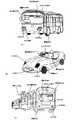
また、本発明を適用して作製される車両の一例としては、図6、図7に図示した乗用車の他、スポーツカー、トラック、バス、ステーションワゴン、特用車(救急車等)、特殊車(トラクター等)及び特装車(タンクローリー車等)等の自動車、電車、自動二輪車などが挙げられる。それらの一例を図7に示す。
【0060】
図7(A)は、カメラ2002、センサ2003、ライト2004、車輪2005及びフロントガラス2006等を含むバスであり、2005は運転手である。フロントガラス2006に車両用表示装置を設置しており、表示部A2000、表示部B2001を表示している。図7(B)は、カメラ2012、センサ2013、ライト2014及び車輪2015を含むスポーツカーであり、2016は運転者である。フロントガラス2017に車両用表示装置を設置しており、表示部A2010を表示している。図7(C)は、カメラ2024、センサ2023、ライト2026及び車輪2025を含む電車であり、2027は運転手である。フロントガラス2028と乗客等を運ぶ車両の窓ガラス2029に車両用表示装置を設置しており、表示部A2021、表示部B2022を表示している。
【0061】
上述のように本発明の車両用表示装置は、透光性体としての機能と画像を表示する機能を兼ね備えているので、実施例のようにフロントガラスや車両側面の窓ガラスに接して設置されても、表示画面の前面からフロントガラスを通して外部を視認することができる。つまり、乗車者は、より多くの情報を得ることができる。
【0062】
また、本実施例のようにフロントガラスに表示部を設けるように本発明を適用し、カーナビゲーションシステムとして用いるのは有益である。カーナビゲーションシステムとは走行中の車両の現在位置・進行方向などの情報を人工衛星・地磁気計・走行距離計などを利用して測定し、車内の画面上に表示して運転者に知らせる装置である。よって、運転者は運転しながらカーナビゲーションシステムを利用することが多い。しかし、従来のナビゲーションシステムでは表示する画面がフロントガラスより下側にあることが多く、運転者は前方から視線を離してしまう危険がある。本発明を用い、前述の車両と車両の外部環境とを検出する検出手段と、その情報を記憶する記憶手段、その情報を表示する表示手段を有し、表示手段により、車両のフロントガラス部分に表示画面を表示する。運転手は車外前方進行方向の人や道の様子を見ながら、カーナビゲーションシステムからの画像による情報を得ることができる。よって、安全かつ便利で快適な運転をすることができる。
【0063】
フロントガラス、リアウインドウガラスに限らず、本発明の車両用表示装置は、車両の車両の側面の窓ガラスやあるいはサンルーフと呼ばれる車両の上方(天井)に設置される窓ガラスどこにでも自由に設置することができる。また本実施例は、上記実施の形態と自由に組み合わせることができる。
【0064】
[実施例2]
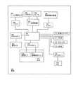
本実施例では、本発明の車両用表示装置を具備した車両の構成要素とそれらの関係について、図4に示すブロック図を用いて説明する。
【0065】
まず、基幹となる構成要素として、表示装置308、車両300の内部に具備されるスピーカ309、車体に取り付けられるマイクロフォン306、外部環境を検出する手段として車間距離や衝撃を検出するセンサ318、撮影する機能をもつカメラ315等が挙げられる。
【0066】
図4に示したように、車両用表示装置308はコントローラ320により制御され、センサ318は衝撃センサ316及び距離測定センサ317を有しており、センサコントローラにより制御される。また操作ボタン302はボタンコントローラ303により制御され、カメラ315はカメラコントローラ314により制御される。これらのコントローラは、CPU301により集中して管理される。そして、CPU301は、フラッシュメモリ312、DRAM311及びVRAM313などの記憶媒体、外部インターフェース310等に接続される。また、キー入力検出センサ305がコントローラ304によって制御され、車両の構成要素がオン状態になる。
【0067】
使用者が操作ボタン302を操作すると、ボタンコントローラ303、CPU301及びコントローラ320を介して車両用表示装置308に情報が表示される。また、使用者が衝撃センサ316、距離測定センサ317を有するセンサ318を操作するときも同じような経路をたどり、はセンサコントローラ319、CPU301及びコントローラ320を介して車両用表示装置308に情報が表示される。
【0068】
使用者が周囲の音を聞く拡声器となるスピーカ309は、マイクロフォン306により周囲の情報を受け取り、その後、CPU301を介してデータ処理回路307に当該情報が供給される。そして、図示しないがD/A変換回路において、アナログの信号に変換され、変換されたアナログ信号がアンプにおいて増幅されて、最終的にスピーカ309に供給される。
【0069】
衝撃を検出する衝撃センサ316や、車間距離を検出する距離測定センサ317から得られた情報は、記憶手段に保存され、CPU301とコントローラ320を介して車両用表示装置308に該情報が表示される。なお、これらのセンサは公知のものを用いればよい。また、撮影する機能を有するカメラ315はカメラコントローラ314により制御され、該カメラコントローラはCPU301により管理される。カメラ315により撮影された画像は、フラッシュメモリ312などの記憶媒体に保存され、CPU301を介して、使用者による操作ボタン302の操作に従って、車両用表示装置308に表示される。
【0070】
このセンサ318及びカメラ315は、より快適で安全な運転のため、アラーム機能として、音声機能と表示機能を連動させて用いることが好適であり、例えば、センサ318から得られた情報を車両用表示装置308に表示し、さらにスピーカ309により運転者に危険を警告してもよい。
【0071】
なお、図示した車両の構成要素はあくまで一例であり、その他の構成要素を具備してもよい。また本実施例は、上記の実施の形態及び実施例と自由に組み合わせることが可能である。
【0072】
[実施例3]
本実施例を図8を用いて説明する。
【0073】
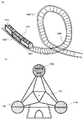
本発明は、車両の他、ゲームセンターや遊園地、テーマパークなどの施設で用いられる遊技器具にも適用することができる。もちろん家庭用のテレビゲーム機やパチンコ用やスロットマシン用の表示装置などにも適用でき、その大きさや形状に限定されない。本発明を適用して作製した遊技器具の例を図8に示す。
【0074】
図8(a)は、遊園地やテーマパークなどに設置されるジェットコースター1001であり、ジェットコースター壁面の透光性の窓ガラス部分に本発明の車両用表示装置を設けている。窓ガラス1003、1004、1005には、その面に沿って表示装置が設けられており、利用者の利便性を高める情報を表示することができる。よって内部にいる乗客は表示された画像からの情報と、車両外部の風景などを同時に見ることができる。
【0075】
図8(b)は、観覧車1101であり、観覧車の乗客が乗る箱型の乗り物に設置された透光性の窓ガラス部分に、本発明の車両用表示装置を設けている。窓ガラス1102、1104、1105には、その面に沿って表示装置が設けられており、利用者の利便性を高める情報を表示することができる。よって内部にいる乗客は表示された画像からの情報と、車両外部の風景などを同時に見ることができる。
【0076】
上述のように、遊技器具を使用する遊技者は、遊技を楽しみながら必要な情報を得ることができる。また、画像と外の風景や景色を同時に見られることにより、一層の臨場感を体験することができる。また、遊技器具として演出に自由さがでて、演出効果も高まる。
【0077】
[実施例4]
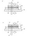
本発明の車両用表示装置を図10に示す。
【0078】
本発明の車両用表示装置の例を図10(a)(b)に示す。透光性基板401及び402は、間に第1の透光性電極405、発光性物質403、第2の透光性電極404を有している。また、第1の透光性電極と第2の透光性電極は、第1の偏光板409と第2の偏光板410に挟まれている。
【0079】
図10(a)においては、第1の偏光板409と第2の偏光板410は光を偏光する向きが同じである。表示素子から射出した光は透光性基板401、402両面から射出する。また矢印411が示すように、フロントガラス406に入射した光も第2の透光性基板401を通過して、射出する。つまり透光性を有する車両用表示装置としての機能を有し、用いることができる。
【0080】
一方、図10(b)においては、第1の偏光板409と第2の偏光板410は光を偏光する向きが異なっている。表示素子から射出した光は透光性基板401、402両面から射出する。しかし矢印412で示すように、フロントガラス406に入射した光は、第1の偏光板409と第2の偏光板410に遮断され、第2の透光性基板401から射出できない。よって非透光性を有する車両用表示装置となる。
【0081】
このように乗車者は偏光板の偏光の向きの組み合わせを、操作することによって、表示部を透光性にも非透光性にもすることができる。これにより、車両表示装置としての利用の自由度が向上し、状況やニーズに合わせた表示を楽しむことができる。
【0082】
【発明の効果】
本発明の車両用表示装置は、画像を表示する表示機能を有し、かつ透光性であるという機能を有している。
【0083】
よって、車両用表示装置をフロントガラスやバックガラスなどに有した車両は、表示された画像を見ながら、同時に車両用表示装置を透して反対側の様子も見ることが出来る。本発明により高機能、高付加価値を付与された車両用表示装置を提供することができる。
【0084】
また、本発明の車両用表示装置は、遊技器具にも用いることが出来る。本発明の車両用表示装置は、画像と画像を透した反対側の風景や景色を同時に見ることができるため、遊技者は、より臨場感のある体験をすることができ、さらに必要な情報をアトラクションを楽しみながら得ることが出来る。
【図面の簡単な説明】
【図1】本発明の構成を示す図。
【図2】本発明の構成を示す図。
【図3】本発明を示す断面図。
【図4】本発明の車両のシステムを示す図。
【図5】本発明の車両用表示装置を示す図。
【図6】本発明の車両用表示装置を示す図。
【図7】本発明の車両用表示装置を示す図。
【図8】本発明の遊技器具を示す図。
【図9】本発明の車両用表示装置を示す図。
【図10】本発明の車両用表示装置を示す図。
【図11】本発明の車両用表示装置を示す図。
【図12】本発明の車両用表示装置を示す図。[0001]
BACKGROUND OF THE INVENTION
The present invention relates to a vehicle display device used in a vehicle.
[0002]
[Prior art]
2. Description of the Related Art There is a vehicle display device provided with display means for displaying an image using a window glass as a screen by irradiating a window glass of the vehicle with a laser beam (see, for example, Patent Document 1).
[0003]
[Patent Document 1]
JP 2000-168352 A
[0004]
[Problems to be solved by the invention]
It is an object of the present invention to provide a display device for a vehicle that realizes higher display function and higher added value.
[0005]
[Means for Solving the Problems]
The vehicular display device of the present invention is a vehicular display device in which the outside of the vehicle can be visually recognized from the front surface of the display screen through the window glass, and the display screen is formed of a translucent substance and the translucent substance. The display screen can be a part or all of the display surface, and the display screen changes according to the external environment of the vehicle to display information. It is characterized by doing.
[0006]
The vehicular display device of the present invention is a vehicular display device in which the outside of the vehicle can be visually recognized from the front surface of the display screen through the window glass, and the display screen is formed of a translucent substance and the translucent substance. The display screen is formed of a pair of translucent electrodes formed, and the display screen can have a part or the whole as a display surface, and has external environment detection means for detecting an external environment of the vehicle, The information obtained by the environment detecting means is displayed by changing the display screen.
[0007]
The vehicular display device of the present invention is a vehicular display device in which the outside of the vehicle can be visually recognized from the front surface of the display screen through the window glass, and the display screen is formed of a translucent substance and the translucent substance. It is formed from a pair of formed translucent electrodes, and the display screen can be partly or entirely the display surface, and detects the vehicle position information and the vehicle external environment obtained from the position information. And detecting means for storing the information obtained by the detecting means, and displaying the information on the display screen.
[0008]
The said structure WHEREIN: The said display screen of a display apparatus can visually recognize the exterior of a vehicle through a window glass from the non-lighting display part at the time of non-lighting.
[0009]
The structure may further include means for changing a wavelength of light incident on the display screen. By the means, a certain wavelength of light is blocked or absorbed, and only a certain wavelength of light is transmitted. The color of light is changed at the time of incidence and at the time of emission, and enters the vehicle display device. Specifically, light is allowed to pass through colored cellophane paper, glass, plastic, or the like having translucency to change the color of the light. Alternatively, a light-transmitting or semi-light-transmitting inert gas or liquid, or a resin material may be used.
[0010]
When the light whose color is adjusted is incident on the vehicular display device, the image changes in various ways. Since various displays are possible, the range of selection of the user for the display is expanded. Therefore, the user can select an image suitable for his / her psychological state and physical condition. Users can get relaxation effects from images and enjoy comfortable driving. In addition, since the intensity and color of light change due to changes in weather, lighting, and the like, the sharpness of an image can be adjusted by adjusting the color and intensity of light incident on the vehicle display device.
[0011]
The display element may include a substance that changes light transmittance such as a liquid crystal substance between a pair of light-transmitting substances, or may include a light-emitting substance that emits light.
[0012]
As the light-emitting substance, an organic compound material, an inorganic compound material, or a combination thereof can be widely used. Luminescence of a light-emitting substance includes light emission (fluorescence) when returning from the singlet excited state to the ground state and light emission (phosphorescence) when returning from the triplet excited state to the ground state. The luminescent materials that can be used in the present invention include all luminescent materials that emit light through singlet excitation, triplet excitation, or both.
[0013]
Moreover, as a translucent substance, quartz, glass (for example, alkali-free glass, tempered glass, or heat-resistant glass), plastic (for example, PES (polyethersulfone), PET (polyethylene terephthalate), PEN (polyethylene naphthalate)) Or PI (polyimide), etc., and other flexible plastic substrates may be used. When a flexible substrate is used, it can be fixed along a curved surface of a vehicle windshield.
[0014]
The vehicle display device of the present invention has a display function of displaying an image and a function of being translucent. Therefore, it can be used without disturbing the visual field of the user.
[0015]
Moreover, the structure which pinched | interposed the vehicle display apparatus of this invention which has the said structure between a pair of polarizing plates may be sufficient. When the polarization directions of the pair of polarizing plates are aligned, it can be used as a translucent vehicle display device. When the polarization directions of the polarizing plates are varied by 90 degrees, the vehicle display device is Cannot pass through, and the display screen becomes non-translucent regardless of whether it is lit or not. The degree of translucency depends on the direction of the polarizing plates.
[0016]
In the above configuration, there may be a plurality of display screens, and any size or shape may be used. Therefore, the degree of freedom in design increases. In general, a state in which the display element is sealed is referred to as a panel, and a state in which an IC such as a controller is mounted on the panel is referred to as a module. Here, the display device is a generic name for the panel and the module.
[0017]
Since the vehicle display device of the present invention has translucency, it does not hinder the driver's field of view, so it can be installed over the vehicle window glass (front glass, side window glass, rear window glass). it can. In addition, it is useful because the driver and passengers can obtain necessary information while looking at the outside scenery. In addition, since a camera and a sensor are installed in the vehicle and speed and surrounding information can be displayed, the driver can drive more safely and comfortably. As described above, according to the present invention, it is possible to provide a display device for a vehicle provided with a high function and a high added value.
[0018]
DETAILED DESCRIPTION OF THE INVENTION
Embodiments of the present invention will be described in detail with reference to the drawings.
[0019]
(Embodiment 1)
An example of a vehicle equipped with the vehicle display device of the present invention is shown in FIGS. As shown in FIG. 1A, the
[0020]
The
[0021]
FIG. 1B is a diagram showing an example in which the vehicle display device of the present invention is installed on a windshield of a vehicle such as a passenger car. With the configuration shown in FIG. 1A, the
[0022]
The size of the
[0023]
Although FIG. 1 shows the case where the
[0024]
Therefore, when the vehicle display device of the present invention is used, the user can view the image and the outside of the vehicle at the same time, and while viewing the outside of the vehicle while obtaining information from the displayed image, the user can drive safely. It is possible and convenient.
[0025]
(Embodiment 2)
Examples of vehicles equipped with the vehicle display device of the present invention are shown in FIGS. 2 (a), (b), FIG. 11, FIG. 12 (a), and (b). As shown in FIG. 2A, the
[0026]
There is a
[0027]
Therefore, the user can adjust the display image to match the user's psychological state and physical condition. The user can obtain a relaxation effect from the displayed image and enjoy a comfortable driving.
[0028]
This
[0029]
FIG. 2B is a view showing an example in which the vehicle display device of the present invention is installed on a windshield of a vehicle such as a passenger car. With the configuration shown in FIG. 2A, the
[0030]
12A shows a
[0031]
Since the liquid crystal element is an element that changes the light transmittance and displays an image, a light source is required. In the present embodiment, light (sunlight or the like) from the outside of the vehicle is reflected using the reflecting
[0032]
Therefore, the driver can safely drive while obtaining information from the image displayed on the windshield, which is convenient. Further, the display device for a vehicle of the present invention is thin and light, and can be sufficiently used even in a narrow space such as the inside of a vehicle.
[0033]
Next, FIG. 11 shows an example in which the display image is variously adjusted as shown in FIG. 2 and a reflector is used as shown in FIG. In FIG. 11, after the incident light 503 passes through the filter 505, the
[0034]
Since the user can operate the
[0035]
By making light adjusted to a certain wavelength incident on the vehicle display device, the display image is diversified, and a display image that matches the psychological state and physical condition of the user can be selected. Users can get relaxation effects from images and enjoy comfortable driving. In addition, since the intensity and color of light change due to changes in weather, lighting, and the like, the sharpness of an image can be adjusted by adjusting the light incident on the vehicle display device.
[0036]
(Embodiment 3)
In this embodiment, the detailed structure of the vehicle display device of the present invention will be described with reference to FIG.
[0037]
FIG. 3A shows an active matrix type vehicle display device using a transistor. A
[0038]
FIG. 3B shows a passive vehicle display device. A first light-transmitting
[0039]
FIG. 3C illustrates a vehicle display device using a liquid crystal element instead of a light emitting element as a display element. The light-transmitting
[0040]
Since the vehicle display device of the present invention has translucency, it can be used without hindering the field of view even if it is fixed to an arbitrary place such as a window glass of a vehicle. Therefore, it is convenient for the user to view the outside of the vehicle while obtaining information from the displayed image and to drive safely.
[0041]
Subsequently, a vehicle display device having an image sensor function different from the above will be described with reference to FIG.
[0042]
In FIG. 9, a
[0043]
The vehicle display device having the above structure includes a first light-transmitting
[0044]
That is, the
[0045]
9 illustrates the case where the light-emitting element and the photoelectric conversion element are formed over the same substrate, the passive light-emitting element and the photoelectric conversion element illustrated in FIG. 3B are formed over the same substrate. May be. Further, although the case where the
[0046]
Note that the display device for a vehicle described with reference to FIG. 3 has a structure in which a display element is stacked on a light-transmitting substrate. However, the present invention is not limited to this, and transfer is performed using a peeling method. You may form by doing. The method will be described below.
[0047]
First, a
[0048]
Further, in the vehicle display device in FIG. 3, after the
[0049]
In this embodiment, an example in which a thin film transistor (TFT) of a crystalline semiconductor is used as a switch element or a drive element is given, but the present invention is not particularly limited to this. For example, amorphous semiconductor thin film transistors, MOS transistors, organic transistors, and the like can be used in the same manner.
[0050]
【Example】
[Example 1]
This embodiment will be described with reference to FIGS.
[0051]
FIG. 5 is an internal view of the driver's seat of the vehicle, in which 2000 is a handle, 2001 is a windshield, 2007 is a glass support, and 2008 is an operation button. The vehicle display device of the present invention is installed in a
[0052]
In this embodiment, the vehicle display device of the present invention is installed in the
[0053]
As the display units A2002 to E2006, it is possible to display information such as a car navigation image for guiding the driver to the driver, a speedometer, a clock, and the like. The user operates the display screen with the
[0054]
6A is a top view of the vehicle, FIG. 6B is a front side view, and FIG. 6C is a rear side view. 6A to 6C, 2102 is a windshield, 2103a, 2103b, 2103c and 2103d are cameras, 2104a and 2104b are sensors, 2105a and 2105b are lights, 2106 is a bumper, 2107 is a wheel, 2109 is a CPU, 2110 is a driver and 2111 is a back glass. Although not shown, the vehicle has an energy source such as electricity and gasoline, and a prime mover that supplies power such as an engine, a power transmission device, a brake device, a steering device, a suspension device, auxiliary equipment, and accessories. It has. In addition, the number of cameras, sensors, and microphones and the installation location are not limited to the illustrated case, and can be arbitrarily determined.
[0055]
A vehicle display device is installed on the windshield 2102 and the rear window glass 2111 which is a rear window. Since the vehicular display device of the present invention has a translucent function and a function of displaying an image, it can display an image as needed while protecting a passenger without disturbing the field of view. That is, it is possible to provide a vehicle with further high functionality and high added value.
[0056]
Since the vehicle display device of the present invention has translucency, it does not hinder the driver's 2110 field of view. Therefore, like display A2101, a clock display image, a speedometer display image, or the like can be displayed on the windshield. The content to be displayed and switching between display and non-display can be operated as needed by the driver by button operation.
[0057]
Moreover, you may display the information which can install
[0058]
In this embodiment, the obstacle sensor reacts, and the display unit B2108 is operated in conjunction with the CPU 2109. In this embodiment, a warning is displayed, but the camera 2103d may display obstacles and the state of the vehicle as images to notify the driver and people outside the vehicle. Thus, the vehicle provided with the vehicle display device of the present invention is a vehicle with high added value that can be driven safely and comfortably for the driver and other pedestrians.
[0059]
Examples of vehicles manufactured by applying the present invention include sports cars, trucks, buses, station wagons, special vehicles (ambulances, etc.), special vehicles (in addition to the passenger cars shown in FIGS. 6 and 7). Vehicles such as tractors) and specially equipped vehicles (such as tank trucks), trains, and motorcycles. An example of them is shown in FIG.
[0060]
FIG. 7A illustrates a bus including a
[0061]
As described above, the display device for a vehicle of the present invention has a function as a translucent body and a function of displaying an image, so that it is installed in contact with a windshield or a window glass on the side of the vehicle as in the embodiment. Even from the front of the display screen, the outside can be seen through the windshield. That is, the passenger can obtain more information.
[0062]
Moreover, it is beneficial to apply the present invention so as to provide a display portion on the windshield as in this embodiment and to use it as a car navigation system. A car navigation system is a device that measures information such as the current position and traveling direction of a running vehicle using an artificial satellite, geomagnetic meter, odometer, etc., and displays it on the screen inside the vehicle to inform the driver. is there. Therefore, the driver often uses the car navigation system while driving. However, in the conventional navigation system, the screen to be displayed is often located below the windshield, and there is a risk that the driver will take his gaze away from the front. Using the present invention, the vehicle has a detection means for detecting the vehicle and the external environment of the vehicle, a storage means for storing the information, and a display means for displaying the information. Display the display screen. The driver can obtain information by an image from the car navigation system while observing the person in the forward traveling direction and the state of the road. Therefore, safe, convenient and comfortable driving can be performed.
[0063]
The vehicle display device of the present invention is not limited to the windshield and the rear window glass, and can be freely installed anywhere on the window glass on the side of the vehicle of the vehicle or on the upper side (ceiling) of the vehicle called a sunroof. be able to. Further, this embodiment can be freely combined with the above embodiment mode.
[0064]
[Example 2]
In the present embodiment, components of a vehicle equipped with the vehicle display device of the present invention and their relationship will be described with reference to the block diagram shown in FIG.
[0065]
First, a
[0066]
As shown in FIG. 4, the
[0067]
When the user operates the
[0068]
A speaker 309, which serves as a loudspeaker for the user to listen to surrounding sounds, receives surrounding information by the microphone 306, and then the information is supplied to the
[0069]
Information obtained from an
[0070]
The
[0071]
Note that the components of the illustrated vehicle are merely examples, and other components may be included. Further, this embodiment can be freely combined with the above embodiment modes and embodiments.
[0072]
[Example 3]
This embodiment will be described with reference to FIG.
[0073]
The present invention can also be applied to game machines used in facilities such as game centers, amusement parks, and theme parks in addition to vehicles. Of course, the present invention can be applied to a home video game machine, a display device for a pachinko machine, a slot machine, and the like, and the size and shape are not limited. An example of a game machine manufactured by applying the present invention is shown in FIG.
[0074]
FIG. 8A shows a
[0075]
FIG. 8B shows a
[0076]
As described above, a player who uses a gaming machine can obtain necessary information while enjoying a game. In addition, by seeing the image and the scenery and scenery at the same time, you can experience a greater sense of realism. In addition, as a gaming machine, the freedom of production is increased, and the production effect is enhanced.
[0077]
[Example 4]
The vehicle display device of the present invention is shown in FIG.
[0078]
An example of the vehicle display device of the present invention is shown in FIGS. The light-transmitting
[0079]
In FIG. 10A, the first
[0080]
On the other hand, in FIG. 10B, the first
[0081]
In this way, the rider can make the display unit translucent or non-translucent by manipulating the combination of the polarization directions of the polarizing plates. Thereby, the freedom degree of utilization as a vehicle display apparatus improves, and it can enjoy the display according to the condition and needs.
[0082]
【The invention's effect】
The vehicle display device of the present invention has a display function of displaying an image and a function of being translucent.
[0083]
Therefore, a vehicle having a vehicle display device on a windshield, a back glass, etc. can see the opposite side through the vehicle display device at the same time while viewing the displayed image. According to the present invention, it is possible to provide a display device for a vehicle provided with high functions and high added value.
[0084]
The vehicle display device of the present invention can also be used for a game machine. The vehicular display device of the present invention allows the player to have a more realistic experience because he / she can see the image and the scenery and scenery on the opposite side through the image at the same time. You can get it while enjoying the attractions.
[Brief description of the drawings]
FIG. 1 is a diagram showing a configuration of the present invention.
FIG. 2 is a diagram showing a configuration of the present invention.
FIG. 3 is a cross-sectional view showing the present invention.
FIG. 4 is a diagram showing a vehicle system of the present invention.
FIG. 5 is a diagram showing a display device for a vehicle according to the present invention.
FIG. 6 is a diagram showing a vehicle display device of the present invention.
FIG. 7 is a diagram showing a vehicle display device of the present invention.
FIG. 8 is a view showing a gaming machine of the present invention.
FIG. 9 is a diagram showing a vehicle display device of the present invention.
FIG. 10 is a diagram showing a vehicle display device of the present invention.
FIG. 11 is a diagram showing a vehicle display device of the present invention.
FIG. 12 is a diagram showing a vehicle display device of the present invention.
Claims (11)
Translated fromJapanese前記表示画面は透光性物質と、前記透光性物質に形成された一対の透光性電極とから形成され、
前記表示画面は、一部または全面を表示面とすることができ、
前記車両の外部環境に応じて、前記表示画面が変化し情報を表示することを特徴とする車両用表示装置。From the front of the display screen, through the window glass, a vehicle display device that can visually recognize the outside of the vehicle,
The display screen is formed of a translucent substance and a pair of translucent electrodes formed on the translucent substance,
The display screen may be partly or entirely the display surface.
The vehicle display device, wherein the display screen changes according to an external environment of the vehicle to display information.
前記表示画面は透光性物質と、前記透光性物質に形成された一対の透光性電極とから形成され、
前記表示画面は、一部または全面を表示面とすることができ、
前記車両の外部環境を検出する外部環境検出手段を有し、
前記外部環境検出手段により得られた情報を、前記表示画面が変化し表示することを特徴とする車両用表示装置。From the front of the display screen, through the window glass, a vehicle display device that can visually recognize the outside of the vehicle,
The display screen is formed of a translucent substance and a pair of translucent electrodes formed on the translucent substance,
The display screen may be partly or entirely the display surface.
An external environment detection means for detecting an external environment of the vehicle;
A display device for vehicles, wherein the display screen changes and displays information obtained by the external environment detection means.
前記表示画面は透光性物質と、前記透光性物質に形成された一対の透光性電極とから形成され、
前記表示画面は、一部または全面を表示面とすることができ、
前記車両の位置情報、及び前記位置情報から得られる車両外部環境を検出する検出手段と、前記検出手段によって得られる情報を記憶する記憶手段とを有し、
前記情報を前記表示画面に表示することを特徴とする車両用表示装置。From the front of the display screen, through the window glass, a vehicle display device that can visually recognize the outside of the vehicle,
The display screen is formed of a translucent substance and a pair of translucent electrodes formed on the translucent substance,
The display screen may be partly or entirely the display surface.
Detecting means for detecting the position information of the vehicle and a vehicle external environment obtained from the position information; and storing means for storing information obtained by the detecting means;
A vehicle display device that displays the information on the display screen.
Priority Applications (1)
| Application Number | Priority Date | Filing Date | Title |
|---|---|---|---|
| JP2003153646AJP4472272B2 (en) | 2003-05-30 | 2003-05-30 | Display system |
Applications Claiming Priority (1)
| Application Number | Priority Date | Filing Date | Title |
|---|---|---|---|
| JP2003153646AJP4472272B2 (en) | 2003-05-30 | 2003-05-30 | Display system |
Publications (3)
| Publication Number | Publication Date |
|---|---|
| JP2004354792Atrue JP2004354792A (en) | 2004-12-16 |
| JP2004354792A5 JP2004354792A5 (en) | 2006-07-13 |
| JP4472272B2 JP4472272B2 (en) | 2010-06-02 |
Family
ID=34048504
Family Applications (1)
| Application Number | Title | Priority Date | Filing Date |
|---|---|---|---|
| JP2003153646AExpired - Fee RelatedJP4472272B2 (en) | 2003-05-30 | 2003-05-30 | Display system |
Country Status (1)
| Country | Link |
|---|---|
| JP (1) | JP4472272B2 (en) |
Cited By (18)
| Publication number | Priority date | Publication date | Assignee | Title |
|---|---|---|---|---|
| JP2006239197A (en)* | 2005-03-04 | 2006-09-14 | Mitsubishi Electric System & Service Co Ltd | Mobile communication terminal machine |
| KR100659709B1 (en) | 2005-08-30 | 2006-12-21 | 한국철도기술연구원 | Lightweight Trainer Operating Panel with Operation Switch |
| WO2007020840A1 (en)* | 2005-08-19 | 2007-02-22 | Adc Technology Inc. | In-car image display device |
| JP2009223023A (en)* | 2008-03-17 | 2009-10-01 | Lintec Corp | See-through type light emitting sheet and method of manufacturing the same |
| JP2012510394A (en)* | 2008-11-28 | 2012-05-10 | ディーア・アンド・カンパニー | Power vehicle control system |
| WO2013088511A1 (en)* | 2011-12-13 | 2013-06-20 | パイオニア株式会社 | Display device, display method, head-up display, and detection device |
| JP2016095331A (en)* | 2014-11-12 | 2016-05-26 | 旭硝子株式会社 | Device and method for peeling substrate |
| CN107089191A (en)* | 2016-02-18 | 2017-08-25 | 索尼公司 | Active window for information of vehicles He virtual reality |
| JP2017189998A (en)* | 2016-04-11 | 2017-10-19 | トヨタ自動車株式会社 | Vehicle display device |
| KR20180070732A (en)* | 2016-12-16 | 2018-06-27 | 현대자동차주식회사 | Display device and Vehicle having the same and method for controlling the same |
| JP2018149988A (en)* | 2017-03-14 | 2018-09-27 | 森尾電機株式会社 | On-vehicle marker device |
| CN108732753A (en)* | 2017-04-18 | 2018-11-02 | 通用汽车环球科技运作有限责任公司 | Selective viewpoint imaging display system |
| JP6433629B1 (en)* | 2017-12-22 | 2018-12-05 | 堺ディスプレイプロダクト株式会社 | Display device and manufacturing method of display device |
| JP2018198071A (en)* | 2018-07-24 | 2018-12-13 | エイディシーテクノロジー株式会社 | On-vehicle image display device |
| JP2020023293A (en)* | 2018-08-08 | 2020-02-13 | 豊 川口 | vehicle |
| JPWO2020194722A1 (en)* | 2019-03-28 | 2020-10-01 | ||
| WO2020220528A1 (en)* | 2019-04-30 | 2020-11-05 | 深圳市华星光电技术有限公司 | Head-up display system for automobile, and automobile |
| US10976617B2 (en) | 2017-12-22 | 2021-04-13 | Sakai Display Products Corporation | Display apparatus and method for manufacturing display apparatus |
Families Citing this family (1)
| Publication number | Priority date | Publication date | Assignee | Title |
|---|---|---|---|---|
| FR3003196B1 (en)* | 2013-03-15 | 2018-01-19 | Saint-Gobain Glass France | GLAZING COMPRISING A TRANSPARENT SCREEN. |
- 2003
- 2003-05-30JPJP2003153646Apatent/JP4472272B2/ennot_activeExpired - Fee Related
Cited By (36)
| Publication number | Priority date | Publication date | Assignee | Title |
|---|---|---|---|---|
| JP2006239197A (en)* | 2005-03-04 | 2006-09-14 | Mitsubishi Electric System & Service Co Ltd | Mobile communication terminal machine |
| US7847705B2 (en) | 2005-08-19 | 2010-12-07 | Adc Technology Inc. | In-vehicle image display apparatus |
| JP2011076631A (en)* | 2005-08-19 | 2011-04-14 | Adc Technology Inc | On-board image display device |
| JP2007052719A (en)* | 2005-08-19 | 2007-03-01 | Adc Technology Kk | In-vehicle image display device |
| US8264367B2 (en) | 2005-08-19 | 2012-09-11 | Adc Technology, Inc. | In-vehicle image display apparatus |
| JP2010225165A (en)* | 2005-08-19 | 2010-10-07 | Adc Technology Inc | In-vehicle image display device |
| US8446289B2 (en) | 2005-08-19 | 2013-05-21 | Adc Technology, Inc. | In-vehicle image display apparatus |
| JP2011076630A (en)* | 2005-08-19 | 2011-04-14 | Adc Technology Inc | On-board image display device |
| WO2007020840A1 (en)* | 2005-08-19 | 2007-02-22 | Adc Technology Inc. | In-car image display device |
| JP2011181110A (en)* | 2005-08-19 | 2011-09-15 | Adc Technology Inc | On-board image display device |
| US8022836B2 (en) | 2005-08-19 | 2011-09-20 | Adc Technology Inc. | In-vehicle image display apparatus |
| JP2011233173A (en)* | 2005-08-19 | 2011-11-17 | Adc Technology Inc | On-vehicle image display device |
| US8456290B2 (en) | 2005-08-19 | 2013-06-04 | Adc Technology Inc. | In-vehicle image display apparatus |
| US8237580B2 (en) | 2005-08-19 | 2012-08-07 | Adc Technology Inc. | In-vehicle image display apparatus |
| KR100659709B1 (en) | 2005-08-30 | 2006-12-21 | 한국철도기술연구원 | Lightweight Trainer Operating Panel with Operation Switch |
| JP2009223023A (en)* | 2008-03-17 | 2009-10-01 | Lintec Corp | See-through type light emitting sheet and method of manufacturing the same |
| JP2012510394A (en)* | 2008-11-28 | 2012-05-10 | ディーア・アンド・カンパニー | Power vehicle control system |
| WO2013088511A1 (en)* | 2011-12-13 | 2013-06-20 | パイオニア株式会社 | Display device, display method, head-up display, and detection device |
| JP2016095331A (en)* | 2014-11-12 | 2016-05-26 | 旭硝子株式会社 | Device and method for peeling substrate |
| US10682911B2 (en) | 2016-02-18 | 2020-06-16 | Sony Corporation | Active window for vehicle infomatics and virtual reality |
| KR20170097560A (en)* | 2016-02-18 | 2017-08-28 | 소니 주식회사 | Active window for vehicle infomatics and virtual reality |
| JP2017151981A (en)* | 2016-02-18 | 2017-08-31 | ソニー株式会社 | Active windows for vehicle informatics and virtual reality |
| KR101906711B1 (en)* | 2016-02-18 | 2018-12-05 | 소니 주식회사 | Active window for vehicle infomatics and virtual reality |
| CN107089191A (en)* | 2016-02-18 | 2017-08-25 | 索尼公司 | Active window for information of vehicles He virtual reality |
| JP2017189998A (en)* | 2016-04-11 | 2017-10-19 | トヨタ自動車株式会社 | Vehicle display device |
| KR20180070732A (en)* | 2016-12-16 | 2018-06-27 | 현대자동차주식회사 | Display device and Vehicle having the same and method for controlling the same |
| KR102586614B1 (en)* | 2016-12-16 | 2023-10-12 | 현대자동차주식회사 | Display device and Vehicle having the same and method for controlling the same |
| JP2018149988A (en)* | 2017-03-14 | 2018-09-27 | 森尾電機株式会社 | On-vehicle marker device |
| CN108732753A (en)* | 2017-04-18 | 2018-11-02 | 通用汽车环球科技运作有限责任公司 | Selective viewpoint imaging display system |
| CN108732753B (en)* | 2017-04-18 | 2022-03-11 | 通用汽车环球科技运作有限责任公司 | Selective viewpoint imaging display system |
| JP6433629B1 (en)* | 2017-12-22 | 2018-12-05 | 堺ディスプレイプロダクト株式会社 | Display device and manufacturing method of display device |
| US10976617B2 (en) | 2017-12-22 | 2021-04-13 | Sakai Display Products Corporation | Display apparatus and method for manufacturing display apparatus |
| JP2018198071A (en)* | 2018-07-24 | 2018-12-13 | エイディシーテクノロジー株式会社 | On-vehicle image display device |
| JP2020023293A (en)* | 2018-08-08 | 2020-02-13 | 豊 川口 | vehicle |
| JPWO2020194722A1 (en)* | 2019-03-28 | 2020-10-01 | ||
| WO2020220528A1 (en)* | 2019-04-30 | 2020-11-05 | 深圳市华星光电技术有限公司 | Head-up display system for automobile, and automobile |
Also Published As
| Publication number | Publication date |
|---|---|
| JP4472272B2 (en) | 2010-06-02 |
Similar Documents
| Publication | Publication Date | Title |
|---|---|---|
| JP4472272B2 (en) | Display system | |
| KR102553434B1 (en) | Lamp for vehicle | |
| US11267313B2 (en) | Vehicular vision system with enhanced functionality | |
| KR102130800B1 (en) | Vehicle control device and vehicle comprising the same | |
| KR102387613B1 (en) | Interface system for vehicle | |
| KR101916725B1 (en) | Lamp for vehicle and method for controlling the same | |
| EP3571084B1 (en) | User interface apparatus for vehicle and vehicle | |
| ES2690394T3 (en) | Information provision procedure and corresponding information provider vehicle | |
| US20070146481A1 (en) | Rear view mirror for a motor vehicle | |
| EP3422081B1 (en) | Head-up display device for vehicle | |
| CN109895788A (en) | The controller of vehicle and method for controlling a vehicle being installed on vehicle | |
| US20070279756A1 (en) | Rearview Mirror For A Motor Vehicle | |
| JP2002200936A (en) | Display device and vehicle | |
| CN109835257A (en) | Display device and vehicle with the display device | |
| JP2010532287A (en) | Display device for automobile and display method using the same | |
| JP2019124930A (en) | Through-material illumination | |
| US11460626B2 (en) | Autonomous vehicle console | |
| CN109398223A (en) | Vehicle lamp and vehicle | |
| JP2016040159A (en) | Vehicle panel module | |
| KR20180070732A (en) | Display device and Vehicle having the same and method for controlling the same | |
| CN112918250A (en) | Intelligent display system and automobile | |
| JP6310826B2 (en) | In-vehicle display device and instrument panel | |
| JP2016060255A (en) | On-vehicle display device and instrument panel | |
| JP2020117123A (en) | Head-up display device | |
| KR20090034109A (en) | Organic electroluminescent device and manufacturing method thereof |
Legal Events
| Date | Code | Title | Description |
|---|---|---|---|
| A521 | Request for written amendment filed | Free format text:JAPANESE INTERMEDIATE CODE: A523 Effective date:20060530 | |
| A621 | Written request for application examination | Free format text:JAPANESE INTERMEDIATE CODE: A621 Effective date:20060530 | |
| A131 | Notification of reasons for refusal | Free format text:JAPANESE INTERMEDIATE CODE: A131 Effective date:20090630 | |
| A521 | Request for written amendment filed | Free format text:JAPANESE INTERMEDIATE CODE: A523 Effective date:20090824 | |
| A131 | Notification of reasons for refusal | Free format text:JAPANESE INTERMEDIATE CODE: A131 Effective date:20091027 | |
| A521 | Request for written amendment filed | Free format text:JAPANESE INTERMEDIATE CODE: A523 Effective date:20091216 | |
| TRDD | Decision of grant or rejection written | ||
| A01 | Written decision to grant a patent or to grant a registration (utility model) | Free format text:JAPANESE INTERMEDIATE CODE: A01 Effective date:20100302 | |
| A01 | Written decision to grant a patent or to grant a registration (utility model) | Free format text:JAPANESE INTERMEDIATE CODE: A01 | |
| A61 | First payment of annual fees (during grant procedure) | Free format text:JAPANESE INTERMEDIATE CODE: A61 Effective date:20100303 | |
| FPAY | Renewal fee payment (event date is renewal date of database) | Free format text:PAYMENT UNTIL: 20130312 Year of fee payment:3 | |
| R150 | Certificate of patent or registration of utility model | Ref document number:4472272 Country of ref document:JP Free format text:JAPANESE INTERMEDIATE CODE: R150 Free format text:JAPANESE INTERMEDIATE CODE: R150 | |
| FPAY | Renewal fee payment (event date is renewal date of database) | Free format text:PAYMENT UNTIL: 20130312 Year of fee payment:3 | |
| FPAY | Renewal fee payment (event date is renewal date of database) | Free format text:PAYMENT UNTIL: 20130312 Year of fee payment:3 | |
| FPAY | Renewal fee payment (event date is renewal date of database) | Free format text:PAYMENT UNTIL: 20140312 Year of fee payment:4 | |
| R250 | Receipt of annual fees | Free format text:JAPANESE INTERMEDIATE CODE: R250 | |
| R250 | Receipt of annual fees | Free format text:JAPANESE INTERMEDIATE CODE: R250 | |
| R250 | Receipt of annual fees | Free format text:JAPANESE INTERMEDIATE CODE: R250 | |
| R250 | Receipt of annual fees | Free format text:JAPANESE INTERMEDIATE CODE: R250 | |
| R250 | Receipt of annual fees | Free format text:JAPANESE INTERMEDIATE CODE: R250 | |
| R250 | Receipt of annual fees | Free format text:JAPANESE INTERMEDIATE CODE: R250 | |
| LAPS | Cancellation because of no payment of annual fees |