JP2004353750A - Neutral control device for automatic transmission for vehicles - Google Patents
Neutral control device for automatic transmission for vehiclesDownload PDFInfo
- Publication number
- JP2004353750A JP2004353750AJP2003151479AJP2003151479AJP2004353750AJP 2004353750 AJP2004353750 AJP 2004353750AJP 2003151479 AJP2003151479 AJP 2003151479AJP 2003151479 AJP2003151479 AJP 2003151479AJP 2004353750 AJP2004353750 AJP 2004353750A
- Authority
- JP
- Japan
- Prior art keywords
- neutral control
- neutral
- gear
- automatic transmission
- engagement
- Prior art date
- Legal status (The legal status is an assumption and is not a legal conclusion. Google has not performed a legal analysis and makes no representation as to the accuracy of the status listed.)
- Granted
Links
Images


Classifications
- F—MECHANICAL ENGINEERING; LIGHTING; HEATING; WEAPONS; BLASTING
- F16—ENGINEERING ELEMENTS AND UNITS; GENERAL MEASURES FOR PRODUCING AND MAINTAINING EFFECTIVE FUNCTIONING OF MACHINES OR INSTALLATIONS; THERMAL INSULATION IN GENERAL
- F16H—GEARING
- F16H61/00—Control functions within control units of change-speed- or reversing-gearings for conveying rotary motion ; Control of exclusively fluid gearing, friction gearing, gearings with endless flexible members or other particular types of gearing
- F16H61/20—Preventing gear creeping ; Transmission control during standstill, e.g. hill hold control
- F—MECHANICAL ENGINEERING; LIGHTING; HEATING; WEAPONS; BLASTING
- F16—ENGINEERING ELEMENTS AND UNITS; GENERAL MEASURES FOR PRODUCING AND MAINTAINING EFFECTIVE FUNCTIONING OF MACHINES OR INSTALLATIONS; THERMAL INSULATION IN GENERAL
- F16H—GEARING
- F16H59/00—Control inputs to control units of change-speed- or reversing-gearings for conveying rotary motion
- F16H59/68—Inputs being a function of gearing status
- F16H59/72—Inputs being a function of gearing status dependent on oil characteristics, e.g. temperature, viscosity
- F16H2059/725—Sensing or calculating temperature of oil in friction devices, e.g. wet clutches, to prevent overheating of friction linings
- F—MECHANICAL ENGINEERING; LIGHTING; HEATING; WEAPONS; BLASTING
- F16—ENGINEERING ELEMENTS AND UNITS; GENERAL MEASURES FOR PRODUCING AND MAINTAINING EFFECTIVE FUNCTIONING OF MACHINES OR INSTALLATIONS; THERMAL INSULATION IN GENERAL
- F16H—GEARING
- F16H61/00—Control functions within control units of change-speed- or reversing-gearings for conveying rotary motion ; Control of exclusively fluid gearing, friction gearing, gearings with endless flexible members or other particular types of gearing
- F16H61/20—Preventing gear creeping ; Transmission control during standstill, e.g. hill hold control
- F16H2061/202—Active creep control for slow driving, e.g. by controlling clutch slip
- F—MECHANICAL ENGINEERING; LIGHTING; HEATING; WEAPONS; BLASTING
- F16—ENGINEERING ELEMENTS AND UNITS; GENERAL MEASURES FOR PRODUCING AND MAINTAINING EFFECTIVE FUNCTIONING OF MACHINES OR INSTALLATIONS; THERMAL INSULATION IN GENERAL
- F16H—GEARING
- F16H2200/00—Transmissions for multiple ratios
- F16H2200/003—Transmissions for multiple ratios characterised by the number of forward speeds
- F16H2200/0052—Transmissions for multiple ratios characterised by the number of forward speeds the gear ratios comprising six forward speeds
- F—MECHANICAL ENGINEERING; LIGHTING; HEATING; WEAPONS; BLASTING
- F16—ENGINEERING ELEMENTS AND UNITS; GENERAL MEASURES FOR PRODUCING AND MAINTAINING EFFECTIVE FUNCTIONING OF MACHINES OR INSTALLATIONS; THERMAL INSULATION IN GENERAL
- F16H—GEARING
- F16H2200/00—Transmissions for multiple ratios
- F16H2200/20—Transmissions using gears with orbital motion
- F16H2200/2002—Transmissions using gears with orbital motion characterised by the number of sets of orbital gears
- F16H2200/2007—Transmissions using gears with orbital motion characterised by the number of sets of orbital gears with two sets of orbital gears
- F—MECHANICAL ENGINEERING; LIGHTING; HEATING; WEAPONS; BLASTING
- F16—ENGINEERING ELEMENTS AND UNITS; GENERAL MEASURES FOR PRODUCING AND MAINTAINING EFFECTIVE FUNCTIONING OF MACHINES OR INSTALLATIONS; THERMAL INSULATION IN GENERAL
- F16H—GEARING
- F16H2200/00—Transmissions for multiple ratios
- F16H2200/20—Transmissions using gears with orbital motion
- F16H2200/202—Transmissions using gears with orbital motion characterised by the type of Ravigneaux set
- F16H2200/2023—Transmissions using gears with orbital motion characterised by the type of Ravigneaux set using a Ravigneaux set with 4 connections
Landscapes
- Engineering & Computer Science (AREA)
- General Engineering & Computer Science (AREA)
- Mechanical Engineering (AREA)
- Control Of Transmission Device (AREA)
Abstract
Translated fromJapaneseDescription
Translated fromJapanese【0001】
【発明の属する技術分野】
本発明は車両用自動変速機に係り、特に、走行用変速段での運転時に動力伝達を遮断するニュートラル制御の改良に関するものである。
【0002】
【従来の技術】
(a) 所定の係合要素が係合させられることによって走行用変速段が成立させられる自動変速機と、(b) 前記走行用変速段での運転時に、予め定められたニュートラル実行条件を満足する場合に前記係合要素を解放乃至はスリップ状態として動力伝達を遮断するニュートラル制御を実行するニュートラル手段と、を有する車両用自動変速機のニュートラル制御装置が知られている。特許文献1に記載の装置はその一例で、クリープトルクの発生を防止するとともにエンジン負荷を低減して燃費を向上させることを目的として、車両停止時にニュートラル制御を実行するが、ポンプの容積効率が悪化する高油温時には復帰の際の応答性を考慮してニュートラル制御を中止するようになっている。
【0003】
【特許文献1】
特開平4−77828号公報
【特許文献2】
特開平9−112673号公報
【特許文献3】
特開2000−220703号公報
【0004】
【発明が解決しようとする課題】
ところで、上記係合要素としては一般に摩擦によって係合力を発生する摩擦係合装置が用いられるとともに、ニュートラル制御時には、復帰時の応答性やショックなどを考慮してスリップ制御(所謂半クラッチ状態)する場合が多いが、このようにスリップ制御を行うと、熱負荷により摩擦係合装置の耐久性が損なわれる可能性がある。このため、摩擦材の枚数を多くしたり摩擦材の耐熱性を強化したり或いは冷却用オイルの供給量を増加したりして摩擦係合装置の耐久性を向上させることが考えられるが、装置が複雑になったりコストが高くなったりして好ましくない。また、熱負荷が高い時には、摩擦係合装置を保護するためにニュートラル制御を一時的に中止することが考えられるが、燃費向上効果が損なわれる。
【0005】
本発明は以上の事情を背景として為されたもので、その目的とするところは、ニュートラル制御による燃費向上効果を維持しつつ摩擦係合装置の耐久性を向上させることにある。
【0006】
【課題を解決するための手段】
かかる目的を達成するために、第1発明は、(a) 所定の係合要素が係合させられることによって走行用変速段が成立させられる自動変速機と、(b) 前記走行用変速段での運転時に、予め定められたニュートラル実行条件を満足する場合に前記係合要素を解放乃至はスリップ状態として動力伝達を遮断するニュートラル制御を実行するニュートラル手段と、を有する車両用自動変速機のニュートラル制御装置において、(c) 前記自動変速機は、複数の係合要素が係合させられることによって前記走行用変速段が成立させられるもので、(d) 前記ニュートラル手段は、前記複数の係合要素のうち前記ニュートラル制御を実行する際に解放乃至はスリップ状態とする係合要素を切り換える選択手段を備えていることを特徴とする。
【0007】
第2発明は、第1発明の車両用自動変速機のニュートラル制御装置において、(a) 前記複数の係合要素は、何れも摩擦によって係合させられる摩擦係合装置で、(b) 前記選択手段は、前記複数の摩擦係合装置の各々の熱負荷状態に基づいて解放乃至はスリップ状態とする摩擦係合装置を選択することを特徴とする。
【0008】
第3発明は、第2発明の車両用自動変速機のニュートラル制御装置において、前記ニュートラル手段は、前記複数の摩擦係合装置の熱負荷が何れも高い場合には前記ニュートラル制御を中止することを特徴とする。
【0009】
第4発明は、第1発明〜第3発明の何れかの車両用自動変速機のニュートラル制御装置において、(a) 前記自動変速機は、変速比が異なる複数の前進変速段を備えており、(b) 前記ニュートラル手段は、前記変速比が最も大きい第1変速段だけでなく、その変速比が2番目に大きい第2変速段以上の前進変速段でも、車両の走行中を含めて前記ニュートラル制御を実行することを特徴とする。
【0010】
【発明の効果】
このような車両用自動変速機のニュートラル制御装置においては、走行用変速段を成立させる際に係合させられる複数の係合要素のうち、ニュートラル制御を実行する際に解放乃至はスリップ状態とする係合要素が選択手段によって切り換えられるため、熱負荷に起因する係合要素の耐久性低下等を回避しつつニュートラル制御を継続して実行することが可能で、ニュートラル制御による燃費向上等の効果が向上する。
【0011】
第3発明では、複数の摩擦係合装置の熱負荷が何れも高い場合にはニュートラル制御を中止するようになっているため、ニュートラル制御に伴う熱負荷により摩擦係合装置の耐久性が損なわれることが防止される。
【0012】
第4発明では、変速比が最も大きい第1変速段だけでなく、変速比が2番目に大きい第2変速段以上の前進変速段でも、車両の走行中を含めてニュートラル制御が実行されるため、車両の停止時や第1変速段のみでニュートラル制御を実行する場合に比較して、ニュートラル制御による燃費向上等の効果が更に向上する。
【0013】
【発明の実施の形態】
本発明は、複数の前進変速段を有する遊星歯車式等の有段変速機のニュートラル制御に好適に適用されるが、前進または後進走行できる走行用変速段が複数の係合要素の係合によって成立させられる種々の自動変速機に適用可能で、単一の前進変速段と動力伝達を遮断するニュートラルとを切り換えるだけのものでも良いし、変速比を連続的に変化させる無段変速機が別個に設けられている場合であっても良い。
【0014】
走行用変速段を成立させる複数の係合要素、言い換えればニュートラル制御で使用できる係合要素は、少なくとも2つで、その何れが解放乃至はスリップ状態とされても動力伝達を遮断できるものである。所定の走行用変速段を成立させる係合要素が3つ以上の場合、単一の係合要素の解放乃至はスリップ状態で動力伝達を遮断するだけでなく、2つの係合要素を同時に解放乃至はスリップ状態とすることにより動力伝達を遮断できる場合であっても良く、動力伝達を遮断できる組合せが2つ以上あれば本発明を適用できる。
【0015】
走行用変速段を成立させる複数の係合要素は、例えば油圧アクチュエータによって摩擦係合させられるクラッチやブレーキ等の油圧式摩擦係合装置が好適に用いられるが、電磁クラッチや噛合いクラッチ等の他の係合要素を採用することも可能で、係合トルクを制御可能な摩擦係合装置等の係合要素についてはスリップ状態によるニュートラル制御が可能である。複数の係合要素は、エンジン等の駆動力源から動力が伝達される入力クラッチなどであるが、反力を受け止める反力ブレーキなどを含んでいても良いなど、種々の態様が可能である。
【0016】
動力伝達を遮断するニュートラル制御は、基本的にエンジン等の駆動力源の負荷を低減して燃費等のエネルギー効率を上昇させるためのもので、係合要素を完全に解放することが望ましいが、係合要素のスリップに伴って多少の動力伝達が行われても差し支えない。なお、車両停止時にニュートラル制御を行えば、クリープトルクの発生を抑制する効果も得られる。
【0017】
ニュートラル制御で使用する係合要素を選択する選択手段は、例えば基本的には複数の係合要素のうち予め定められた何れか1つを選択するが、その係合要素の熱負荷が高くなるなどして使用不可、或いは使用することが適当でなくなった場合には、他の係合要素を用いるように構成されるが、ニュートラル制御を所定回数行う毎、或いは所定時間行う毎に、機械的に係合要素を交互に或いは順番に切り換えるようにしても良いなど、種々の態様が可能である。複数の前進変速段でニュートラル制御を実行する場合、その複数の前進変速段で係合させられる共通の係合要素を基本的に選択するようにすれば、アクセルOFFに伴う車速低下などでダウンシフトが行われる場合でも、他の係合要素の解放や係合によりダウンシフトを行いながらニュートラル制御を継続して行うことができる。
【0018】
第2発明では熱負荷状態に基づいて摩擦係合装置を選択するようになっているが、この場合も熱負荷によって使用不可、或いは使用することが適当でなくなった場合に、他の摩擦係合装置を用いるようにしても良い。熱負荷状態は、例えば摩擦係合装置の表面近傍温度を検出して所定温度以上か否か等によって判断できるが、ニュートラル制御に伴うスリップ状態の継続時間や、スリップ回転速度、入力トルク、ニュートラル制御の実行頻度、スリップ制御を行うべき摩擦係合装置の係合、解放(変速)の履歴や頻度、などから間接的に判断することもできる。
【0019】
第4発明では第2変速段以上の前進変速段や車両走行中にもニュートラル制御が実行され、クラッチツークラッチ変速で且つリニアソレノイド弁などにより摩擦係合装置の係合トルク(油圧)が直接制御される場合に好適に適用されるが、他の発明の実施に際しては、第1変速段のみでニュートラル制御を行ったり、車両停止時のみニュートラル制御を行ったり、後進変速段でニュートラル制御を行ったりするなど、種々の態様が可能である。
【0020】
【実施例】
以下、本発明の実施例を図面を参照しつつ詳細に説明する。
図1の(a) は、本発明が適用された車両用自動変速機10の骨子図で、(b) は複数の変速段を成立させる際の係合要素を説明する作動表である。この車両用自動変速機10は、FF車両などの横置き用のもので、シングルピニオン型の第1遊星歯車装置12を主体として構成されている第1変速部14と、シングルピニオン型の第2遊星歯車装置16およびダブルピニオン型の第3遊星歯車装置18を主体として構成されている第2変速部20とを同軸線上に有し、入力軸22の回転を変速して出力歯車24から出力する。入力軸22は入力部材に相当するもので、走行用駆動力源としてのエンジン40によって回転駆動されるトルクコンバータ42のタービン軸であり、出力歯車24は出力部材に相当するもので、図示しない差動歯車装置を介して左右の駆動輪を回転駆動する。なお、この車両用自動変速機10は中心線に対して略対称的に構成されており、図1(a) では中心線の下半分が省略されている。
【0021】
上記第1変速部14を構成している第1遊星歯車装置12は、サンギヤS1、プラネタリキャリアCA1、およびリングギヤR1の3つの回転要素を備えており、サンギヤS1が入力軸22に連結されて回転駆動されるとともに、リングギヤR1が第3ブレーキB3を介して回転不能にケース26に固定されることにより、プラネタリキャリアCA1が中間出力部材として入力軸22に対して減速回転させられて出力する。また、第2変速部20を構成している第2遊星歯車装置16および第3遊星歯車装置18は、一部が互いに連結されることによって4つの回転要素RM1〜RM4が構成されており、具体的には、第3遊星歯車装置18のサンギヤS3によって第1回転要素RM1が構成され、第2遊星歯車装置16のリングギヤR2および第3遊星歯車装置18のリングギヤR3が互いに連結されて第2回転要素RM2が構成され、第2遊星歯車装置16のプラネタリキャリアCA2および第3遊星歯車装置18のプラネタリキャリアCA3が互いに連結されて第3回転要素RM3が構成され、第2遊星歯車装置16のサンギヤS2によって第4回転要素RM4が構成されている。上記第2遊星歯車装置16および第3遊星歯車装置18は、キャリアCA2およびCA3が共通の部材にて構成されているとともに、リングギヤR2およびR3が共通の部材にて構成されており、且つ第2遊星歯車装置16のピニオンギヤが第3遊星歯車装置18の第2ピニオンギヤを兼ねているラビニヨ型の遊星歯車列とされている。
【0022】
上記第1回転要素RM1(サンギヤS3)は第1ブレーキB1によって選択的にケース26に連結されて回転停止させられ、第2回転要素RM2(リングギヤR2、R3)は第2ブレーキB2によって選択的にケース26に連結されて回転停止させられ、第4回9要素RM4(サンギヤS2)は第1クラッチC1を介して選択的に前記入力軸22に連結され、第2回転要素RM2(リングギヤR2、R3)は第2クラッチC2を介して選択的に入力軸22に連結され、第1回転要素RM1(サンギヤS3)は中間出力部材である前記第1遊星歯車装置12のプラネタリキャリアCA1に一体的に連結され、第3回転要素RM3(プラネタリキャリアCA2、CA3)は前記出力歯車24に一体的に連結されて回転を出力するようになっている。上記第1ブレーキB1〜第3ブレーキB3、第1クラッチC1、第2クラッチC2(以下、特に区別しない場合は単にブレーキB、クラッチCという)は、何れも油圧アクチュエータによって摩擦係合させられる多板式の油圧式摩擦係合装置で、油圧制御回路98(図3参照)のソレノイド弁Sol1〜Sol5、およびリニアソレノイド弁SL1、SL2の励磁、非励磁や図示しないマニュアルバルブによって油圧回路が切り換えられることにより係合、解放状態が切り換えられる。
【0023】
図2は、上記第1変速部14および第2変速部20の各回転要素の回転速度を直線で表すことができる共線図であり、下の横線が回転速度「0」で、上の横線が回転速度「1.0」すなわち入力軸22と同じ回転速度である。また、第1変速部14の各縦線は、左側から順番にサンギヤS1、キャリアCA1、リングギヤR1を表しており、それ等の間隔は第1遊星歯車装置12のギヤ比(=サンギヤの歯数/リングギヤの歯数)ρ1に応じて定められる。第2変速部20の4本の縦線は、左端から右端へ向かって順番に第1回転要素RM1(サンギヤS3)、第2回転要素RM2(リングギヤR2、R3)、第3回転要素RM3(キャリアCA2、CA3)、第4回転要素RM4(サンギヤS2)を表しており、それ等の間隔は第2遊星歯車装置16のギヤ比ρ2および第3遊星歯車装置18のギヤ比ρ3に応じて定められる。
【0024】
そして、上記共線図から明らかなように、第1クラッチC1および第2ブレーキB2が係合させられて、第4回転要素RM4が入力軸22と一体回転させられるとともに第2回転要素RM2が回転停止させられると、出力歯車24に連結された第3回転要素RM3は「1st」で示す回転速度で回転させられ、変速比(=入力軸22の回転速度Nin/出力歯車24の回転速度Nout )が最も大きい第1変速段「1st」が成立させられる。第1クラッチC1および第1ブレーキB1が係合させられて、第4回転要素RM4が入力軸22と一体回転させられるとともに第1回転要素RM1が回転停止させられると、第3回転要素RM3は「2nd」で示す回転速度で回転させられ、第1変速段「1st」よりも変速比が小さい第2変速段「2nd」が成立させられる。第1クラッチC1および第3ブレーキB3が係合させられて、第4回転要素RM4が入力軸22と一体回転させられるとともに第1回転要素RM1が第1変速部14を介して減速回転させられると、第3回転要素RM3は「3rd」で示す回転速度で回転させられ、第2変速段「2nd」よりも変速比が小さい第3変速段「3rd」が成立させられる。第1クラッチC1および第2クラッチC2が係合させられて、第2変速部20が入力軸22と一体回転させられると、第3回転要素RM3は「4th」で示す回転速度すなわち入力軸22と同じ回転速度で回転させられ、第3変速段「3rd」よりも変速比が小さい第4変速段「4th」が成立させられる。この第4変速段「4th」の変速比は1である。第2クラッチC2および第3ブレーキB3が係合させられて、第2回転要素RM2が入力軸22と一体回転させられるとともに第1回転要素RM1が第1変速部14を介して減速回転させられると、第3回転要素RM3は「5th」で示す回転速度で回転させられ、第4変速段「4th」よりも変速比が小さい第5変速段「5th」が成立させられる。第2クラッチC2および第1ブレーキB1が係合させられて、第2回転要素RM2が入力軸22と一体回転させられるとともに第1回転要素RM1が回転停止させられると、第3回転要素RM3は「6th」で示す回転速度で回転させられ、第5変速段「5th」よりも変速比が小さい第6変速段「6th」が成立させられる。また、第2ブレーキB2および第3ブレーキB3が係合させられると、第2回転要素RM2が回転停止させられるとともに第1回転要素RM1が第1変速部14を介して減速回転させられることにより、第3回転要素RM3は「Rev」で示す回転速度で逆回転させられ、後進変速段「Rev」が成立させられる。
【0025】
図1の(b) の作動表は、上記各変速段とクラッチC1、C2、ブレーキB1〜B3の作動状態との関係をまとめたもので、「○」は係合、「×」は解放を表しており、本実施例では総ての前進変速段の切換えに際して、何れか1つの摩擦係合装置を解放するとともに他の1つの摩擦係合装置を係合させるクラッチツークラッチ変速が行われる。また、第1変速段「1st」〜第6変速段「6th」の各前進変速段は走行用変速段で、何れも2つのクラッチCおよび3つのブレーキBのうちの所定の2つが係合させられることによって成立させられ、その2つの摩擦係合装置の何れか1つが解放或いはスリップ状態とされることにより、動力伝達が遮断されてニュートラルになる。本実施例では、摩擦係合装置であるクラッチCおよびブレーキBが複数の係合要素に相当する。なお、各変速段の変速比は、第1遊星歯車装置12、第2遊星歯車装置16、および第3遊星歯車装置18の各ギヤ比ρ1、ρ2、ρ3によって適宜定められる。
【0026】
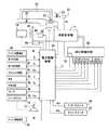
図3は、図1の自動変速機10やエンジン40などを制御するために車両に設けられた制御系統を説明するブロック線図で、アクセルペダル50の操作量Accがアクセル操作量センサ51により検出されるようになっている。アクセルペダル50は、運転者の出力要求量に応じて大きく踏み込み操作されるもので、アクセル操作部材に相当し、アクセル操作量Accは出力要求量に相当する。エンジン40の吸気配管には、スロットルアクチュエータ54によってアクセル操作量Accに応じた開き角(開度)θTHとされる電子スロットル弁56が設けられている。また、アイドル回転速度制御のために上記電子スロットル弁56をバイパスさせるバイパス通路52には、エンジン40のアイドル回転速度NEIDLを制御するために電子スロットル弁56の全閉時の吸気量を制御するISC(アイドル回転速度制御)バルブ53が設けられている。この他、エンジン40の回転速度NEを検出するためのエンジン回転速度センサ58、エンジン40の吸入空気量Qを検出するための吸入空気量センサ60、吸入空気の温度TAを検出するための吸入空気温度センサ62、上記電子スロットル弁56の全閉状態(アイドル状態)およびその開度θTHを検出するためのアイドルスイッチ付スロットルセンサ64、車速V(出力歯車24の回転速度Nout に対応)を検出するための車速センサ66、エンジン40の冷却水温TWを検出するための冷却水温センサ68、常用ブレーキであるフットブレーキの操作の有無を検出するためのブレーキスイッチ70、シフトレバー72のレバーポジション(操作位置)PSHを検出するためのレバーポジションセンサ74、タービン回転速度NT(=入力軸22の回転速度Nin)を検出するためのタービン回転速度センサ76、油圧制御回路98内の作動油の温度であるAT油温TOILを検出するためのAT油温センサ78、アップシフトスイッチ80、ダウンシフトスイッチ82などが設けられており、それらのセンサやスイッチから、エンジン回転速度NE、吸入空気量Q、吸入空気温度TA、スロットル弁開度θTH、車速V、エンジン冷却水温TW、ブレーキ操作の有無、シフトレバー72のレバーポジションPSH、タービン回転速度NT、AT油温TOIL、変速レンジのアップ指令RUP、ダウン指令RDN、などを表す信号が電子制御装置90に供給されるようになっている。
【0027】
上記シフトレバー72は運転席の近傍に配設され、例えば「R(リバース)」、「N(ニュートラル)」、「D(ドライブ)」、および「S(シーケンシャル)」の4つのポジションへ選択的に手動操作されるようになっている。「R」ポジションは後進走行位置で、「N」ポジションは動力伝達遮断位置で、「D」ポジションは自動変速による前進走行位置で、「S」ポジションは変速可能な高速側の変速段が異なる複数の変速レンジを切り換えることにより手動変速が可能な前進走行位置であり、シフトレバー72がどのレバーポジションへ操作されているかが前記レバーポジションセンサ74によって検出される。そして、「D」ポジションの自動変速では、例えば車速Vおよびスロットル弁開度θTH等の運転状態をパメラータとして予め定められた変速マップ(変速条件)に従って、第1変速段「1st」〜第6変速段「6th」の総ての変速段を用いて自動的に変速が行われる一方、「S」ポジションでは、前記アップシフトスイッチ80、ダウンシフトスイッチ82から供給されるアップ指令RUPやダウン指令RDNに従って、最高速段すなわち変速比が小さい高速側の変速範囲が異なる複数の変速レンジが電気的に成立させられる。
【0028】
前記電子制御装置90は、CPU、RAM、ROM、入出力インターフェース等を備えた所謂マイクロコンピュータを含んで構成されており、CPUはRAMの一時記憶機能を利用しつつ予めROMに記憶されたプログラムに従って信号処理を行うことにより、エンジン40の出力制御や自動変速機10の変速制御などを実行するようになっており、必要に応じてエンジン制御用と変速制御用とに分けて構成される。
【0029】
電子制御装置90はまた、シフトレバー72がDポジションへ操作された前進走行の自動変速モード時に、図4のフローチャートに従ってアクセルOFF時等に所定のクラッチCまたはブレーキBをスリップ制御して動力伝達を遮断するニュートラル制御を実行する機能を備えている。電子制御装置90による一連の信号処理のうち図4の各ステップS1〜S6を実行する部分はニュートラル手段に相当し、そのうちのステップS3〜S6を実行する部分は選択手段に相当する。
【0030】
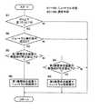
図4のステップS1では、自動変速機10の変速段が第4変速段「4th」以下で且つ車速Vが予め定められた所定車速V1以下であるか否かを判断し、満足する場合はステップS2を実行する。第4変速段「4th」以下に限定したのは、走行中のニュートラル制御時には車速Vの低下に伴ってダウンシフトが行われる可能性があるが、第4変速段「4th」以下では第1クラッチC1が共通の係合要素として係合させられ、他の係合要素(C2、B1〜B3)を切り換えて変速が行われるため、基本的に第1クラッチC1をニュートラル制御の制御対象として用いることにより、ダウンシフトに拘らずスリップ制御を継続して行うことができるからである。また、所定車速V1は、アクセルOFF時にエンジン40の燃料供給を停止するフューエルカット制御を実行する車速よりも低車速か否かを判断するためのもので、変速段毎に設定されている。これは、フューエルカット制御が実行されれば、ニュートラル制御を行ってエンジン負荷を軽減する必要が無いため、フューエルカット制御が実行される所定車速V1より高車速ではニュートラル制御を行わないようにしたのであり、エンジン回転速度NEが所定値以下か否か、或いはフューエルカット制御のON、OFFなどで判断することもできる。
【0031】
ステップS2では、予め定められたニュートラル実行条件を満足するか否かを判断する。ニュートラル実行条件は、例えば(a) アクセル操作量θTHが略0或いはアイドルスイッチがONのアクセルOFF、(b) 道路勾配が略0°の平坦路、(c) AT油温TOILが所定範囲内、(d) シフトレバー72がDポジションの自動変速モードなどで、それ等の総てを満足する場合にステップS3以下を実行する。
【0032】
ステップS3では、第1摩擦係合装置すなわちニュートラル制御の基本的な制御対象である第1クラッチC1の熱負荷が所定値以下か否かを判断し、所定値以下であればステップS5で、その第1クラッチC1をスリップ状態としてニュートラル制御を実行する。しかし、第1クラッチC1の熱負荷が所定値より高い場合にはステップS4を実行し、第2摩擦係合装置すなわち第1変速段「1st」〜第4変速段「4th」で摩擦係合させられる一対の摩擦係合装置のうち第1摩擦係合装置(第1クラッチC1)以外の摩擦係合装置で、第1変速段「1st」では第2ブレーキB2、第2変速段「2nd」では第1ブレーキB1、第3変速段「3rd」では第3ブレーキB3、第4変速段「4th」では第2クラッチC2、の熱負荷が所定値以下か否かを判断し、所定値以下であればステップS6で、その第2摩擦係合装置をスリップ状態としてニュートラル制御を実行するが、所定値より高い場合はニュートラル制御を中止する。ニュートラル制御は、解除時の応答性を考慮して、例えばエンジン回転速度NEとタービン回転速度NTとの比が所定値(例えば1.0程度)となるように、第1クラッチC1または第2摩擦係合装置の係合トルク具体的には油圧をリニアソレノイド弁などで制御して所定のスリップ状態、或いはスリップ直前の解放状態とする。
【0033】
上記ステップS3、S4は、第1クラッチC1等の摩擦係合装置をスリップ制御した場合に熱負荷で摩擦材等の耐久性が著しく損なわれる可能性があるなど、スリップ制御の制御対象として使用することが適当でないか否かを判断するためのもので、例えば各摩擦係合装置(クラッチCおよびブレーキB)の表面近傍温度を検出して所定温度以上か否か等によって判断できるが、本実施例では、その摩擦係合装置に対するニュートラル制御(スリップ制御)の継続時間や、スリップ回転速度、入力トルク、ニュートラル制御の実行頻度、スリップ制御を行う摩擦係合装置の係合、解放(変速)の履歴や頻度、などから熱負荷を間接的に判断するようになっている。
【0034】
このように、本実施例の車両用自動変速機10のニュートラル制御では、第1変速段「1st」〜第4変速段「4th」を成立させる際に係合させられるそれぞれ一対ずつの摩擦係合装置(クラッチCおよびブレーキB)のうち、ニュートラル制御を実行する際にスリップ状態とする摩擦係合装置が熱負荷に応じて切り換えられるため、熱負荷に起因する摩擦係合装置の耐久性低下等を回避しつつニュートラル制御を継続して実行することが可能で、ニュートラル制御による燃費向上等の効果が向上する。
【0035】
また、一対の摩擦係合装置の熱負荷が何れも高く、ステップS3およびS4の判断が何れもNOの場合には、ニュートラル制御を中止するようになっているため、ニュートラル制御に伴う熱負荷により摩擦係合装置の耐久性が損なわれることが防止される。
【0036】
また、変速比が最も大きい第1変速段「1st」だけでなく、第4変速段「4th」以下の各変速段において、車両の走行中を含めてニュートラル制御が実行されるため、車両の停止時や第1変速段「1st」のみでニュートラル制御を実行する場合に比較して、ニュートラル制御による燃費向上等の効果が更に向上する。
【0037】
また、第1クラッチC1が共通の係合要素として係合させられる第1変速段「1st」〜第4変速段「4th」でニュートラル制御が行われるとともに、その第1クラッチC1が第1摩擦係合装置として基本的にニュートラル制御の制御対象とされるため、他の係合要素(C2、B1〜B3)を切り換えてダウンシフトしながらスリップ制御を継続して行うことができる。
【0038】
また、エンジン40の燃料供給を停止するフューエルカット制御が行われる所定車速V1よりも高車速か否かを判断し、所定車速V1よりも高車速のフューエルカット領域ではニュートラル制御が行われないため、燃費向上に寄与しない無駄なニュートラル制御が防止される。
【0039】
以上、本発明の実施例を図面に基づいて詳細に説明したが、これはあくまでも一実施形態であり、本発明は当業者の知識に基づいて種々の変更,改良を加えた態様で実施することができる。
【図面の簡単な説明】
【図1】本発明が適用された車両用自動変速機を説明する図で、(a) は骨子図、(b) は各変速段を成立させるための作動表である。
【図2】図1の自動変速機の共線図である。
【図3】図1の車両用自動変速機が備えている制御系統の要部を説明するブロック線図である。
【図4】図1の自動変速機のニュートラル制御に関して図3の電子制御装置が備えている機能を具体的に説明するフローチャートである。
【符号の説明】
10:車両用自動変速機 90:電子制御装置 C1、C2:クラッチ(係合要素、摩擦係合装置) B1、B2、B3:ブレーキ(係合要素、摩擦係合装置)
ステップS1〜S6:ニュートラル手段
ステップS3〜S6:選択手段[0001]
TECHNICAL FIELD OF THE INVENTION
The present invention relates to an automatic transmission for a vehicle, and more particularly to an improvement in a neutral control that cuts off power transmission during operation at a traveling speed.
[0002]
[Prior art]
(A) an automatic transmission in which a traveling gear is established by engaging a predetermined engagement element; and (b) a predetermined neutral execution condition is satisfied during operation at the traveling gear. In such a case, a neutral control device for an automatic transmission for a vehicle having a neutral means for executing a neutral control for interrupting the power transmission by disengaging the engagement element or turning off the slipping state is known. The device described in
[0003]
[Patent Document 1]
JP-A-4-77828 [Patent Document 2]
Japanese Patent Application Laid-Open No. 9-112673 [Patent Document 3]
JP-A-2000-220703
[Problems to be solved by the invention]
By the way, a frictional engagement device that generates an engagement force by friction is generally used as the engagement element, and a slip control (a so-called half-clutch state) is performed in neutral control in consideration of a response at the time of return, a shock, and the like. In many cases, when the slip control is performed in this manner, the durability of the friction engagement device may be impaired due to a thermal load. Therefore, it is conceivable to improve the durability of the friction engagement device by increasing the number of friction materials, enhancing the heat resistance of the friction materials, or increasing the supply amount of the cooling oil. However, it is not preferable because it complicates and costs increase. When the heat load is high, the neutral control may be temporarily stopped in order to protect the friction engagement device, but the fuel efficiency improvement effect is impaired.
[0005]
The present invention has been made in view of the above circumstances, and an object of the present invention is to improve the durability of the friction engagement device while maintaining the fuel efficiency improving effect of the neutral control.
[0006]
[Means for Solving the Problems]
In order to achieve the above object, the first invention provides (a) an automatic transmission in which a traveling gear is established by engaging a predetermined engagement element; and (b) an automatic transmission in which the traveling gear is established. A neutral means for performing a neutral control for releasing the engagement element or turning off the slipping state to interrupt power transmission when a predetermined neutral execution condition is satisfied during the operation of the automatic transmission for a vehicle. In the control device, (c) the automatic transmission establishes the traveling shift speed by engaging a plurality of engagement elements, and (d) the neutral means controls the plurality of engagements. When executing the neutral control among the elements, there is provided a selection means for switching an engagement element to be in a release or slip state.
[0007]
According to a second aspect, in the neutral control device for a vehicle automatic transmission according to the first aspect, (a) the plurality of engagement elements are friction engagement devices each of which is engaged by friction; The means selects a friction engagement device to be in a release or slip state based on a thermal load state of each of the plurality of friction engagement devices.
[0008]
A third aspect of the present invention is the neutral control device for a vehicle automatic transmission according to the second aspect, wherein the neutral means stops the neutral control when the thermal loads of the plurality of friction engagement devices are all high. Features.
[0009]
A fourth invention is the neutral control device for an automatic transmission for a vehicle according to any one of the first invention to the third invention, wherein: (a) the automatic transmission includes a plurality of forward gears having different gear ratios; (B) The neutral means includes not only the first gear having the largest gear ratio but also the second gear having the second largest gear ratio, and the neutral gear including the traveling gear. The control is performed.
[0010]
【The invention's effect】
In such a neutral control device for an automatic transmission for a vehicle, among a plurality of engagement elements that are engaged when establishing a gear position for traveling, a release or slip state is set when the neutral control is executed. Since the engagement element is switched by the selection means, it is possible to continuously execute the neutral control while avoiding a decrease in the durability of the engagement element due to a thermal load, and the effect of improving the fuel efficiency by the neutral control can be obtained. improves.
[0011]
In the third aspect, when the thermal loads of the plurality of friction engagement devices are all high, the neutral control is stopped, so that the durability of the friction engagement devices is impaired by the thermal load associated with the neutral control. Is prevented.
[0012]
According to the fourth aspect, the neutral control is performed not only at the first speed stage having the highest speed ratio but also at the forward speed stages equal to or higher than the second speed stage having the second highest speed ratio, including during traveling of the vehicle. As compared with the case where the vehicle is stopped or the neutral control is executed only at the first shift speed, the effect of the neutral control such as improvement in fuel efficiency is further improved.
[0013]
BEST MODE FOR CARRYING OUT THE INVENTION
The present invention is suitably applied to neutral control of a stepped transmission such as a planetary gear type having a plurality of forward gears. The present invention is applicable to various automatic transmissions that can be established, and may be one that simply switches between a single forward gear and a neutral state that shuts off power transmission, or a continuously variable transmission that continuously changes the gear ratio. May be provided.
[0014]
There are at least two engaging elements that establish the traveling speed, that is, at least two engaging elements that can be used in the neutral control, and can interrupt power transmission even when any of the engaging elements is released or slipped. . When there are three or more engagement elements for establishing a predetermined traveling gear, not only is the release of a single engagement element or the power transmission interrupted in a slip state, but also the simultaneous release or release of two engagement elements May be a case in which power transmission can be interrupted by setting a slip state, and the present invention can be applied as long as there are two or more combinations capable of interrupting power transmission.
[0015]
As the plurality of engagement elements for establishing the traveling gear, for example, a hydraulic friction engagement device such as a clutch or a brake frictionally engaged by a hydraulic actuator is preferably used. The engagement element such as a friction engagement device capable of controlling the engagement torque can be neutrally controlled by the slip state. The plurality of engagement elements are input clutches or the like to which power is transmitted from a driving force source such as an engine, but may have various modes such as a reaction force brake for receiving a reaction force.
[0016]
Neutral control for interrupting power transmission is basically for reducing the load on a driving force source such as an engine to increase energy efficiency such as fuel efficiency, and it is desirable to completely release the engagement element. Some power transmission may be performed with the slippage of the engagement element. If the neutral control is performed when the vehicle is stopped, the effect of suppressing the generation of creep torque can be obtained.
[0017]
The selection means for selecting the engagement element used in the neutral control, for example, basically selects any one of a plurality of engagement elements in advance, but the heat load of the engagement element increases. When it becomes impossible to use or becomes unsuitable for use, other engagement elements are used. However, every time the neutral control is performed a predetermined number of times or every predetermined time, a mechanical control is performed. Various modes are possible, for example, the engagement elements may be switched alternately or sequentially. When the neutral control is executed at a plurality of forward gears, if a common engagement element to be engaged at the plurality of forward gears is basically selected, a downshift occurs due to a decrease in vehicle speed due to an accelerator OFF or the like. Is performed, the neutral control can be continuously performed while performing the downshift by releasing or engaging the other engagement elements.
[0018]
In the second invention, the frictional engagement device is selected based on the thermal load state. In this case, however, if the thermal load makes the device unusable or unsuitable for use, another frictional engagement device is selected. An apparatus may be used. The thermal load state can be determined, for example, by detecting the temperature near the surface of the friction engagement device and determining whether the temperature is equal to or higher than a predetermined temperature. However, the duration of the slip state associated with the neutral control, the slip rotation speed, the input torque, the neutral control Can be indirectly determined from the execution frequency, the history and frequency of engagement and disengagement (shift) of the friction engagement device for which slip control is to be performed, and the like.
[0019]
In the fourth aspect of the invention, the neutral control is also executed during the forward speed beyond the second speed and during the traveling of the vehicle, and the engagement torque (oil pressure) of the friction engagement device is directly controlled by the clutch-to-clutch speed change and the linear solenoid valve. In other embodiments, the present invention is preferably applied to the case where the neutral control is performed only at the first shift speed, the neutral control is performed only when the vehicle is stopped, or the neutral control is performed at the reverse shift speed. Various modes are possible.
[0020]
【Example】
Hereinafter, embodiments of the present invention will be described in detail with reference to the drawings.
FIG. 1A is a skeleton diagram of an
[0021]
The first
[0022]
The first rotary element RM1 (sun gear S3) is selectively connected to the
[0023]
FIG. 2 is a collinear diagram that can represent the rotation speed of each rotating element of the
[0024]
Then, as is clear from the alignment chart, the first clutch C1 and the second brake B2 are engaged, the fourth rotating element RM4 is integrally rotated with the
[0025]
The operation table of FIG. 1 (b) summarizes the relationship between the above-mentioned gears and the operating states of the clutches C1, C2 and the brakes B1 to B3, where "○" indicates engagement and "x" indicates release. In this embodiment, at the time of switching of all forward gears, a clutch-to-clutch shift is performed in which any one friction engagement device is released and another friction engagement device is engaged. Each of the forward gears from the first gear “1st” to the sixth gear “6th” is a traveling gear, and all two of the two clutches C and the three brakes B are engaged. When one of the two frictional engagement devices is released or slipped, the power transmission is cut off and the transmission becomes neutral. In the present embodiment, the clutch C and the brake B, which are friction engagement devices, correspond to a plurality of engagement elements. The gear ratio of each gear is appropriately determined by the gear ratios ρ1, ρ2, and ρ3 of the first
[0026]
FIG. 3 is a block diagram illustrating a control system provided in the vehicle for controlling the
[0027]
The
[0028]
The
[0029]
The
[0030]
In step S1 of FIG. 4, it is determined whether or not the shift speed of the
[0031]
In step S2, it is determined whether or not a predetermined neutral execution condition is satisfied. Neutral execution conditions include, for example, (a) accelerator operation amount θTH is approximately 0 or an accelerator is OFF when an idle switch is ON, (b) a flat road with a road gradient of approximately 0 °, and (c) AT oil temperature TOIL is within a predetermined range. Among them, (d) when the
[0032]
In step S3, it is determined whether the heat load of the first clutch C1, which is a basic control target of the first frictional engagement device, that is, the neutral control, is equal to or less than a predetermined value. The neutral control is executed with the first clutch C1 in the slip state. However, if the heat load of the first clutch C1 is higher than the predetermined value, step S4 is executed to frictionally engage the second frictional engagement device, that is, the first gear "1st" to the fourth gear "4th". A friction engagement device other than the first friction engagement device (first clutch C1) among the pair of friction engagement devices to be used, the second brake B2 at the first shift speed "1st", and the second brake B2 at the second shift speed "2nd" It is determined whether the thermal load of the third brake B3 at the first brake B1 and the third shift stage "3rd" and the thermal load of the second clutch C2 at the fourth shift stage "4th" is below a predetermined value. For example, in step S6, the second frictional engagement device is set in the slip state to execute the neutral control. If the second frictional engagement device is higher than the predetermined value, the neutral control is stopped. In the neutral control, the first clutch C1 or the second friction is set such that the ratio between the engine rotation speed NE and the turbine rotation speed NT becomes a predetermined value (for example, about 1.0) in consideration of the response at the time of release. The engagement torque of the engagement device, specifically, the hydraulic pressure is controlled by a linear solenoid valve or the like to set a predetermined slip state or a release state immediately before the slip.
[0033]
Steps S3 and S4 are used as control objects of the slip control, for example, when the frictional engagement device such as the first clutch C1 is slip-controlled, the durability of the friction material or the like may be significantly impaired by a thermal load. This is for determining whether or not the temperature is not appropriate. For example, the temperature near the surface of each friction engagement device (clutch C and brake B) can be detected to determine whether the temperature is equal to or higher than a predetermined temperature. In the example, the duration of the neutral control (slip control) for the friction engagement device, the slip rotation speed, the input torque, the execution frequency of the neutral control, the engagement and disengagement (shift) of the friction engagement device performing the slip control. The heat load is indirectly determined from the history and frequency.
[0034]
As described above, in the neutral control of the
[0035]
Further, when the thermal loads of the pair of frictional engagement devices are both high and the determinations in steps S3 and S4 are both NO, the neutral control is stopped, so that the thermal load associated with the neutral control causes The durability of the friction engagement device is prevented from being impaired.
[0036]
In addition, the neutral control is performed not only at the first gear "1st" having the largest gear ratio but also at each gear lower than the fourth gear "4th". Compared with the case where the neutral control is executed only at the time or the first shift speed "1st", the effect such as improvement of fuel efficiency by the neutral control is further improved.
[0037]
Further, the neutral control is performed in the first shift speed "1st" to the fourth shift speed "4th" in which the first clutch C1 is engaged as a common engagement element, and the first clutch C1 is engaged with the first frictional engagement. Since the joint device is basically controlled by the neutral control, the slip control can be continuously performed while downshifting by switching the other engagement elements (C2, B1 to B3).
[0038]
Further, it is determined whether or not the vehicle speed is higher than a predetermined vehicle speed V1 at which the fuel cut control for stopping the fuel supply to the
[0039]
Although the embodiment of the present invention has been described in detail with reference to the drawings, this is merely an embodiment, and the present invention is embodied in various modified and improved forms based on the knowledge of those skilled in the art. Can be.
[Brief description of the drawings]
FIGS. 1A and 1B are diagrams illustrating an automatic transmission for a vehicle to which the present invention is applied, wherein FIG. 1A is a skeleton diagram, and FIG. 1B is an operation table for establishing each shift speed.
FIG. 2 is an alignment chart of the automatic transmission of FIG. 1;
FIG. 3 is a block diagram for explaining a main part of a control system provided in the vehicle automatic transmission shown in FIG. 1;
FIG. 4 is a flowchart specifically illustrating functions of the electronic control device of FIG. 3 regarding neutral control of the automatic transmission of FIG. 1;
[Explanation of symbols]
10: Automatic transmission for vehicle 90: Electronic control device C1, C2: Clutch (engagement element, friction engagement device) B1, B2, B3: Brake (engagement element, friction engagement device)
Steps S1 to S6: neutral means Steps S3 to S6: selection means
Claims (4)
Translated fromJapanese前記走行用変速段での運転時に、予め定められたニュートラル実行条件を満足する場合に前記係合要素を解放乃至はスリップ状態として動力伝達を遮断するニュートラル制御を実行するニュートラル手段と、
を有する車両用自動変速機のニュートラル制御装置において、
前記自動変速機は、複数の係合要素が係合させられることによって前記走行用変速段が成立させられるもので、
前記ニュートラル手段は、前記複数の係合要素のうち前記ニュートラル制御を実行する際に解放乃至はスリップ状態とする係合要素を切り換える選択手段を備えている
ことを特徴とする車両用自動変速機のニュートラル制御装置。An automatic transmission in which a traveling gear is established by engagement of a predetermined engagement element;
During operation at the traveling speed, neutral means for executing neutral control for releasing the engagement element or slipping to shut off power transmission when a predetermined neutral execution condition is satisfied,
In a neutral control device for an automatic transmission for a vehicle having
In the automatic transmission, the traveling speed is established by engaging a plurality of engagement elements.
The automatic transmission for a vehicle according to claim 1, wherein the neutral unit includes a selection unit that switches an engagement element to be released or slipped when executing the neutral control among the plurality of engagement elements. Neutral control device.
前記選択手段は、前記複数の摩擦係合装置の各々の熱負荷状態に基づいて解放乃至はスリップ状態とする摩擦係合装置を選択する
ことを特徴とする請求項1に記載の車両用自動変速機のニュートラル制御装置。The plurality of engagement elements are friction engagement devices that are all engaged by friction,
2. The automatic transmission for a vehicle according to claim 1, wherein the selection unit selects a friction engagement device to be in a disengaged or slip state based on a thermal load state of each of the plurality of friction engagement devices. Neutral control of the machine.
ことを特徴とする請求項2に記載の車両用自動変速機のニュートラル制御装置。The neutral control device for an automatic transmission for a vehicle according to claim 2, wherein the neutral means stops the neutral control when the thermal loads of the plurality of friction engagement devices are all high.
前記ニュートラル手段は、前記変速比が最も大きい第1変速段だけでなく、該変速比が2番目に大きい第2変速段以上の前進変速段でも、車両の走行中を含めて前記ニュートラル制御を実行する
ことを特徴とする請求項1〜3の何れか1項に記載の車両用自動変速機のニュートラル制御装置。The automatic transmission includes a plurality of forward gears having different gear ratios,
The neutral means executes the neutral control not only at the first gear stage having the largest gear ratio but also at a forward gear stage greater than or equal to the second gear stage having the second largest gear ratio, including during traveling of the vehicle. The neutral control device for an automatic transmission for a vehicle according to any one of claims 1 to 3, wherein:
Priority Applications (5)
| Application Number | Priority Date | Filing Date | Title |
|---|---|---|---|
| JP2003151479AJP3855966B2 (en) | 2003-05-28 | 2003-05-28 | Neutral control device for automatic transmission for vehicles |
| US10/834,077US7029413B2 (en) | 2003-05-28 | 2004-04-29 | Neutral control for vehicular automatic transmission |
| CN200410042370.8ACN1573174B (en) | 2003-05-28 | 2004-05-20 | Automatic shift system and neutral gear control method for vehicle automatic transmission |
| DE102004025733.7ADE102004025733B8 (en) | 2003-05-28 | 2004-05-26 | Neutral control device for an automatic vehicle transmission |
| FR0405730AFR2855583B1 (en) | 2003-05-28 | 2004-05-27 | CONTROL OF NEUTRAL FOR AUTOMATIC TRANSMISSION OF VEHICLE |
Applications Claiming Priority (1)
| Application Number | Priority Date | Filing Date | Title |
|---|---|---|---|
| JP2003151479AJP3855966B2 (en) | 2003-05-28 | 2003-05-28 | Neutral control device for automatic transmission for vehicles |
Publications (2)
| Publication Number | Publication Date |
|---|---|
| JP2004353750Atrue JP2004353750A (en) | 2004-12-16 |
| JP3855966B2 JP3855966B2 (en) | 2006-12-13 |
Family
ID=33432214
Family Applications (1)
| Application Number | Title | Priority Date | Filing Date |
|---|---|---|---|
| JP2003151479AExpired - Fee RelatedJP3855966B2 (en) | 2003-05-28 | 2003-05-28 | Neutral control device for automatic transmission for vehicles |
Country Status (5)
| Country | Link |
|---|---|
| US (1) | US7029413B2 (en) |
| JP (1) | JP3855966B2 (en) |
| CN (1) | CN1573174B (en) |
| DE (1) | DE102004025733B8 (en) |
| FR (1) | FR2855583B1 (en) |
Cited By (7)
| Publication number | Priority date | Publication date | Assignee | Title |
|---|---|---|---|---|
| WO2009028222A1 (en)* | 2007-08-31 | 2009-03-05 | Aisin Aw Co., Ltd. | Controller for automatic transmission and method for controlling automatic transmission |
| JP2009137329A (en)* | 2007-12-04 | 2009-06-25 | Nissan Motor Co Ltd | Control device for hybrid vehicle |
| JP2010149629A (en)* | 2008-12-24 | 2010-07-08 | Nissan Motor Co Ltd | Drive controller and start control method for vehicle |
| JP2013204684A (en)* | 2012-03-28 | 2013-10-07 | Aisin Aw Co Ltd | Control device and control method for automatic transmission |
| JP2014001834A (en)* | 2012-06-20 | 2014-01-09 | Nissan Motor Co Ltd | Neutral control device for vehicle |
| US8924112B2 (en) | 2010-02-05 | 2014-12-30 | Toyota Jidosha Kabushiki Kaisha | Start control device of power transmission system for vehicle and start control method |
| JPWO2014017356A1 (en)* | 2012-07-27 | 2016-07-11 | ジヤトコ株式会社 | Control device and control method for automatic transmission |
Families Citing this family (20)
| Publication number | Priority date | Publication date | Assignee | Title |
|---|---|---|---|---|
| JP4506286B2 (en)* | 2003-08-19 | 2010-07-21 | 株式会社小松製作所 | Construction machinery |
| DE102006014947A1 (en) | 2006-03-31 | 2007-10-04 | Zf Friedrichshafen Ag | Automatic transmission e.g. step automatic transmission, operating method for motor vehicle, involves closing three switching elements of step automatic transmission for moment and/or power transmission into forward gear and reverse gear |
| DE102006014941A1 (en)* | 2006-03-31 | 2007-05-24 | Zf Friedrichshafen Ag | Operating method e.g. for automatic transmission, involves having automatic transmission having five logic elements, and in moment transmission and or power transmission in forward or reverse gear, three logic elements are closed |
| DE102006014946A1 (en)* | 2006-03-31 | 2007-03-29 | Zf Friedrichshafen Ag | Motor vehicle`s automatic transmission e.g. step-automatic transmission, operating method, involves completely opening one of switching units during gear releasing to transfer transmission from forward or reverse gear into neutral position |
| JP5103992B2 (en)* | 2006-05-29 | 2012-12-19 | 日産自動車株式会社 | Hybrid vehicle control device and hybrid vehicle control method. |
| US7585249B2 (en)* | 2006-06-30 | 2009-09-08 | Gm Global Technology Operations, Inc. | Apparatus and method to control transmission torque output during a gear-to-gear shift |
| KR20080053150A (en)* | 2006-12-09 | 2008-06-12 | 현대자동차주식회사 | Method for controlling shifting during shifting and system thereof |
| JP5056635B2 (en)* | 2007-11-22 | 2012-10-24 | 日産自動車株式会社 | Automatic transmission control device for abnormalities in automatic manual transmission |
| JP5151543B2 (en)* | 2008-02-26 | 2013-02-27 | 日産自動車株式会社 | Automatic transmission starting hydraulic control device |
| CN103492766B (en)* | 2011-03-31 | 2015-12-23 | 爱信艾达株式会社 | The control gear of speed changer and the controlling method of speed changer |
| JP5472227B2 (en)* | 2011-08-08 | 2014-04-16 | アイシン・エィ・ダブリュ株式会社 | Control device |
| WO2013076827A1 (en)* | 2011-11-22 | 2013-05-30 | トヨタ自動車株式会社 | Automatic transmission for vehicle |
| JP5958094B2 (en)* | 2012-05-31 | 2016-07-27 | アイシン・エィ・ダブリュ株式会社 | Control device for vehicle drive device |
| WO2014141368A1 (en)* | 2013-03-11 | 2014-09-18 | トヨタ自動車株式会社 | Control device for automatic transmission |
| US9182036B2 (en)* | 2013-12-24 | 2015-11-10 | GM Global Technology Operations LLC | Binary clutch disengagement control in a neutral shift |
| WO2015129542A1 (en)* | 2014-02-28 | 2015-09-03 | アイシン・エィ・ダブリュ株式会社 | Control device for vehicle drive device |
| DE102014205550A1 (en)* | 2014-03-25 | 2015-10-01 | Siemens Aktiengesellschaft | Transmission system with Ravigneaux set and vehicle |
| CN104455383B (en)* | 2014-09-30 | 2017-03-29 | 浙江吉利汽车研究院有限公司 | A kind of automatic gearbox neutral control method |
| US11105421B2 (en)* | 2016-10-26 | 2021-08-31 | Jatco Ltd | Control device for vehicle and control method for vehicle |
| CN116771817A (en)* | 2023-08-24 | 2023-09-19 | 盛瑞传动股份有限公司 | Control method, device and equipment for gearbox and storage medium |
Family Cites Families (12)
| Publication number | Priority date | Publication date | Assignee | Title |
|---|---|---|---|---|
| JPH0454374A (en) | 1990-06-25 | 1992-02-21 | Honda Motor Co Ltd | Control method for automatic transmission for vehicles |
| JPH0477828A (en) | 1990-07-13 | 1992-03-11 | A T R Koudenpa Tsushin Kenkyusho:Kk | fuzzy inference method |
| JP3417505B2 (en) | 1995-05-12 | 2003-06-16 | アイシン・エィ・ダブリュ株式会社 | Control device for automatic transmission |
| JP2917875B2 (en) | 1995-10-17 | 1999-07-12 | アイシン・エィ・ダブリュ株式会社 | Control device for automatic transmission |
| DE19600739A1 (en)* | 1996-01-11 | 1997-07-17 | Zahnradfabrik Friedrichshafen | Transmission control to reduce the thermal load on switching elements |
| JP3837787B2 (en) | 1996-09-12 | 2006-10-25 | アイシン・エィ・ダブリュ株式会社 | Slip control device |
| JP3634947B2 (en)* | 1997-08-08 | 2005-03-30 | ジヤトコ株式会社 | Neutral control device for automatic transmission |
| JP3601276B2 (en)* | 1997-12-08 | 2004-12-15 | アイシン・エィ・ダブリュ株式会社 | Control device for automatic transmission |
| JP3490277B2 (en) | 1998-01-22 | 2004-01-26 | ジヤトコ株式会社 | Neutral control device for automatic transmission |
| JP4206551B2 (en) | 1998-06-05 | 2009-01-14 | アイシン・エィ・ダブリュ株式会社 | Automatic transmission for vehicles |
| JP3938839B2 (en)* | 2000-09-18 | 2007-06-27 | ジヤトコ株式会社 | Piston stroke end determination device for automatic transmission |
| JP4968494B2 (en) | 2001-03-05 | 2012-07-04 | アイシン・エィ・ダブリュ株式会社 | Vehicle transmission |
- 2003
- 2003-05-28JPJP2003151479Apatent/JP3855966B2/ennot_activeExpired - Fee Related
- 2004
- 2004-04-29USUS10/834,077patent/US7029413B2/ennot_activeExpired - Fee Related
- 2004-05-20CNCN200410042370.8Apatent/CN1573174B/ennot_activeExpired - Fee Related
- 2004-05-26DEDE102004025733.7Apatent/DE102004025733B8/ennot_activeExpired - Fee Related
- 2004-05-27FRFR0405730Apatent/FR2855583B1/ennot_activeExpired - Fee Related
Cited By (11)
| Publication number | Priority date | Publication date | Assignee | Title |
|---|---|---|---|---|
| WO2009028222A1 (en)* | 2007-08-31 | 2009-03-05 | Aisin Aw Co., Ltd. | Controller for automatic transmission and method for controlling automatic transmission |
| JP2009058064A (en)* | 2007-08-31 | 2009-03-19 | Aisin Aw Co Ltd | Control device for automatic transmission and control method for automatic transmission |
| US8185284B2 (en) | 2007-08-31 | 2012-05-22 | Aisin Aw Co. Ltd. | Control device of automatic transmission, and control method of automatic transmission |
| JP2009137329A (en)* | 2007-12-04 | 2009-06-25 | Nissan Motor Co Ltd | Control device for hybrid vehicle |
| JP2010149629A (en)* | 2008-12-24 | 2010-07-08 | Nissan Motor Co Ltd | Drive controller and start control method for vehicle |
| US8924112B2 (en) | 2010-02-05 | 2014-12-30 | Toyota Jidosha Kabushiki Kaisha | Start control device of power transmission system for vehicle and start control method |
| JP2013204684A (en)* | 2012-03-28 | 2013-10-07 | Aisin Aw Co Ltd | Control device and control method for automatic transmission |
| JP2014001834A (en)* | 2012-06-20 | 2014-01-09 | Nissan Motor Co Ltd | Neutral control device for vehicle |
| JPWO2014017356A1 (en)* | 2012-07-27 | 2016-07-11 | ジヤトコ株式会社 | Control device and control method for automatic transmission |
| KR20160139055A (en)* | 2012-07-27 | 2016-12-06 | 쟈트코 가부시키가이샤 | Control device and control method for automatic transmission |
| KR101929107B1 (en) | 2012-07-27 | 2018-12-13 | 쟈트코 가부시키가이샤 | Control device and control method for automatic transmission |
Also Published As
| Publication number | Publication date |
|---|---|
| US20040242359A1 (en) | 2004-12-02 |
| DE102004025733A1 (en) | 2005-01-05 |
| JP3855966B2 (en) | 2006-12-13 |
| FR2855583B1 (en) | 2006-11-24 |
| FR2855583A1 (en) | 2004-12-03 |
| CN1573174B (en) | 2010-04-28 |
| DE102004025733B8 (en) | 2015-02-12 |
| CN1573174A (en) | 2005-02-02 |
| US7029413B2 (en) | 2006-04-18 |
| DE102004025733B4 (en) | 2014-12-11 |
Similar Documents
| Publication | Publication Date | Title |
|---|---|---|
| JP3855966B2 (en) | Neutral control device for automatic transmission for vehicles | |
| CN100494742C (en) | Control device and control method for automatic transmission | |
| CN100414148C (en) | Control equipment for automatic transmissions for vehicles | |
| CN101755150B (en) | Shift control device for automatic transmission for vehicle | |
| JP4162024B2 (en) | Control device for automatic transmission for vehicle | |
| JP2008169874A (en) | Control device for vehicle drive device | |
| JP4690278B2 (en) | Shift control device for automatic transmission | |
| JP4301235B2 (en) | Shift control device for automatic transmission | |
| JP2005273805A (en) | Automatic transmission abnormality detection device | |
| JP4289059B2 (en) | Hydraulic control device for automatic transmission for vehicle | |
| JP4297018B2 (en) | Shift control device for automatic transmission for vehicle | |
| JP2007205431A (en) | Control device for automatic transmission | |
| JP2007224745A (en) | Vehicle control device | |
| JP4736708B2 (en) | Shift control device for automatic transmission | |
| JP2010196766A (en) | Shift control device for automatic transmission for vehicle | |
| JP4696875B2 (en) | Hydraulic control device for automatic transmission for vehicle | |
| JP2008151190A (en) | Control device for automatic transmission for vehicle | |
| JP4821525B2 (en) | Shift control device for automatic transmission | |
| JP5790535B2 (en) | Shift control device for automatic transmission for vehicle | |
| JP4613683B2 (en) | Hydraulic control device for automatic transmission for vehicle | |
| JP4114432B2 (en) | Hydraulic control device for automatic transmission for vehicle | |
| JP5124944B2 (en) | Control device for automatic transmission | |
| JP4539375B2 (en) | Vehicle driving force control device | |
| JP4760308B2 (en) | Hydraulic control device for automatic transmission | |
| JP4984492B2 (en) | Shift control device for automatic transmission |
Legal Events
| Date | Code | Title | Description |
|---|---|---|---|
| A977 | Report on retrieval | Free format text:JAPANESE INTERMEDIATE CODE: A971007 Effective date:20060224 | |
| TRDD | Decision of grant or rejection written | ||
| A01 | Written decision to grant a patent or to grant a registration (utility model) | Free format text:JAPANESE INTERMEDIATE CODE: A01 Effective date:20060822 | |
| A61 | First payment of annual fees (during grant procedure) | Free format text:JAPANESE INTERMEDIATE CODE: A61 Effective date:20060904 | |
| FPAY | Renewal fee payment (event date is renewal date of database) | Free format text:PAYMENT UNTIL: 20100922 Year of fee payment:4 | |
| FPAY | Renewal fee payment (event date is renewal date of database) | Free format text:PAYMENT UNTIL: 20100922 Year of fee payment:4 | |
| FPAY | Renewal fee payment (event date is renewal date of database) | Free format text:PAYMENT UNTIL: 20110922 Year of fee payment:5 | |
| FPAY | Renewal fee payment (event date is renewal date of database) | Free format text:PAYMENT UNTIL: 20110922 Year of fee payment:5 | |
| FPAY | Renewal fee payment (event date is renewal date of database) | Free format text:PAYMENT UNTIL: 20120922 Year of fee payment:6 | |
| FPAY | Renewal fee payment (event date is renewal date of database) | Free format text:PAYMENT UNTIL: 20120922 Year of fee payment:6 | |
| FPAY | Renewal fee payment (event date is renewal date of database) | Free format text:PAYMENT UNTIL: 20130922 Year of fee payment:7 | |
| LAPS | Cancellation because of no payment of annual fees |