JP2004353473A - Control device for internal combustion engine - Google Patents
Control device for internal combustion engineDownload PDFInfo
- Publication number
- JP2004353473A JP2004353473AJP2003149180AJP2003149180AJP2004353473AJP 2004353473 AJP2004353473 AJP 2004353473AJP 2003149180 AJP2003149180 AJP 2003149180AJP 2003149180 AJP2003149180 AJP 2003149180AJP 2004353473 AJP2004353473 AJP 2004353473A
- Authority
- JP
- Japan
- Prior art keywords
- cylinder operation
- value
- ignition timing
- engine
- coefficient
- Prior art date
- Legal status (The legal status is an assumption and is not a legal conclusion. Google has not performed a legal analysis and makes no representation as to the accuracy of the status listed.)
- Pending
Links
Images


Classifications
- Y—GENERAL TAGGING OF NEW TECHNOLOGICAL DEVELOPMENTS; GENERAL TAGGING OF CROSS-SECTIONAL TECHNOLOGIES SPANNING OVER SEVERAL SECTIONS OF THE IPC; TECHNICAL SUBJECTS COVERED BY FORMER USPC CROSS-REFERENCE ART COLLECTIONS [XRACs] AND DIGESTS
- Y02—TECHNOLOGIES OR APPLICATIONS FOR MITIGATION OR ADAPTATION AGAINST CLIMATE CHANGE
- Y02T—CLIMATE CHANGE MITIGATION TECHNOLOGIES RELATED TO TRANSPORTATION
- Y02T10/00—Road transport of goods or passengers
- Y02T10/10—Internal combustion engine [ICE] based vehicles
- Y02T10/12—Improving ICE efficiencies
- Y—GENERAL TAGGING OF NEW TECHNOLOGICAL DEVELOPMENTS; GENERAL TAGGING OF CROSS-SECTIONAL TECHNOLOGIES SPANNING OVER SEVERAL SECTIONS OF THE IPC; TECHNICAL SUBJECTS COVERED BY FORMER USPC CROSS-REFERENCE ART COLLECTIONS [XRACs] AND DIGESTS
- Y02—TECHNOLOGIES OR APPLICATIONS FOR MITIGATION OR ADAPTATION AGAINST CLIMATE CHANGE
- Y02T—CLIMATE CHANGE MITIGATION TECHNOLOGIES RELATED TO TRANSPORTATION
- Y02T10/00—Road transport of goods or passengers
- Y02T10/10—Internal combustion engine [ICE] based vehicles
- Y02T10/40—Engine management systems
Landscapes
- Electrical Control Of Ignition Timing (AREA)
- Output Control And Ontrol Of Special Type Engine (AREA)
Abstract
Translated fromJapaneseDescription
Translated fromJapanese【0001】
【発明の属する技術分野】
本発明は、内燃機関の制御装置に関し、特に複数気筒を有する内燃機関の一部気筒の作動を休止させる気筒休止機構を備えた内燃機関の制御装置に関する。
【0002】
【従来の技術】
気筒休止機構を備えた内燃機関において、一部気筒運転から全筒運転への移行、またはその逆の移行を行うと、トルクショックが発生するため、特許文献1には、このようなトルクショックが発生しないように、スロットル弁の開度を制御する制御装置が示されている。この装置によれば、アクセルペダルの操作量に対応するスロットル弁開度を算出するために、全筒運転用のスロットル弁開度演算テーブルと、一部気筒運転用のスロットル弁開度演算テーブルとを使用し、一部気筒運転から全筒運転への移行、またはその逆の移行時に使用するテーブルを切り換えることが行われる。
【0003】
【特許文献1】
特開昭62−103430号公報
【0004】
【発明が解決しようとする課題】
上記従来の制御装置では、トルクショックを防止するためスロットル弁開度制御において、点火時期の変更によるトルク変動を考慮していないため、以下のような課題があった。
【0005】
機関のノッキングを検出し、その検出結果に応じて点火時期が補正される場合において、例えば低オクタン価の燃料を使用しているときには、点火時期がノッキングの発生状態に応じて、遅角されたり、進角されたりする。また一部気筒運転中においては、全筒運転時に比べて一気筒当たりの負荷が大きくなるため、ノッキングが発生し易く、また点火時期の変化に起因するトルク変化が大きい。そのため、上記従来の制御装置では、点火時期の補正に伴うトルク変動が発生し、トルクショックを十分に低減できない場合があった。
【0006】
本発明はこの点に着目してなされたものであり、点火時期の補正と、作動気筒数の制御(一部気筒運転とするか、全筒運転とするかの選択)とを適切に行い、トルクショックを抑制することができる内燃機関の制御装置を提供することを目的とする。
【0007】
【課題を解決するための手段】
上記目的を達成するため請求項1に記載の発明は、複数気筒を有し、前記複数気筒の全てを作動させる全筒運転と、前記複数気筒のうち一部気筒の作動を休止させる一部気筒運転とを切換える切換手段(30)を備えた内燃機関の制御装置において、前記機関の運転パラメータを含む、前記機関により駆動される車両の運転パラメータ(TW,VP,GP,TH,TA,NE,PBA)を検出する運転パラメータ検出手段と、前記運転パラメータ検出手段により検出される運転パラメータに応じて前記全筒運転または一部気筒運転を前記切換手段(30)に指令する指令手段と、前記機関のノッキングを検出するノッキング検出手段(11,51,52,53)と、前記機関の運転パラメータに応じて前記機関の点火時期(IGCMD)を制御する点火時期制御手段と、前記ノッキング検出手段の検出結果に応じて前記点火時期の補正量(KIGKN)を算出し、該補正量(KIGKN)により前記点火時期を補正する補正する補正手段と、前記点火時期の補正量(KIGKN)に応じて前記一部気筒運転を禁止する禁止手段とを備えることを特徴とする。
【0008】
この構成によれば、ノッキング検出手段の検出結果に応じて点火時期が補正され、その点火時期の補正量に応じて一部気筒運転が禁止される。したがって、点火時期の補正量が大きくなったときに一部気筒運転を禁止することにより、作動気筒数の変更に伴うトルクショックと、点火時期の補正に伴うトルク変化とが重なることがなく、トルクショックを抑制することができる。
【0009】
請求項2に記載の発明は、複数気筒を有し、前記複数気筒の全てを作動させる全筒運転と、前記複数気筒のうち一部気筒の作動を休止させる一部気筒運転とを切換える切換手段(30)を備えた内燃機関の制御装置において、前記機関の運転パラメータを含む、前記機関により駆動される車両の運転パラメータ(TW,VP,GP,TH,TA,NE,PBA)を検出する運転パラメータ検出手段と、前記運転パラメータ検出手段により検出される運転パラメータに応じて前記全筒運転または一部気筒運転を前記切換手段(30)に指令する指令手段と、前記機関のノッキングを検出するノッキング検出手段(11,51,52,53)と、前記機関の運転パラメータに応じて前記機関の点火時期(IGCMD)を制御する点火時期制御手段と、前記ノッキング検出手段の検出結果に応じて前記点火時期の補正量(KIGKN)を算出し、該補正量(KIGKN)により前記点火時期を補正する補正手段と、前記一部気筒運転中は、前記補正手段による点火時期の補正を制限する制限手段とを備えることを特徴とする。
【0010】
この構成によれば、一部気筒運転中は、ノッキング検出手段の検出結果に応じた点火時期の補正が制限されるので、点火時期の補正に伴うトルク変化が抑制される。したがって、作動気筒数の変更に伴うトルクショックを抑制する制御を行うことにより、トルクショックを抑制することができる。
【0011】
前記禁止手段は、前記補正量(KIGKN)が所定補正量(KIGKNCSX)より遅角側の値であるとき、前記一部気筒運転を禁止することが望ましい。また、前記制限手段は、前記補正量(KIGKN)を所定上限値(KIGKNLMH)及び所定下限値(KIGKNLML)で決まる範囲内に制限し、前記所定上限値(KIGKNLMH)は、レギュラーガソリンのオクタン価より低いオクタン価(例えば85程度)の燃料に対応する値とし、前記所定下限値(KIGKNLML)は、レギュラーガソリンのオクタン価(例えば90程度)に対応する値とすることが望ましい。また、前記制限手段は、前記補正量(KIGKN)を一部気筒運転用設定値(KIGKNCS0)に設定してもよい。
【0012】
さらに前記全筒運転中に、前記補正量の学習値(KIGKREFE,KIGKREF)を算出する学習値算出手段(図23,図24の処理))を備え、前記制限手段は、前記学習値(KIGKREFE,KIGKREF)に応じて、前記一部気筒運転用設定値(KIGKNCS0)を算出するようにしてもよい。
【0013】
また、前記切換手段による切換時における前記機関の出力トルクの変動を抑制するように前記機関の吸入空気量を制御する吸入空気量制御手段(図8,図9の処理)をさらに備えることが望ましい。
【0014】
【発明の実施の形態】
以下本発明の実施の形態を図面を参照して説明する。
(第1の実施形態)
図1は本発明の第1の実施形態にかかる内燃機関及びその制御装置の構成を示す図である。V型6気筒の内燃機関(以下単に「エンジン」という)1は、#1,#2及び#3気筒が設けられた右バンクと、#4,#5及び#6気筒が設けられた左バンクとを備え、右バンクには#1〜#3気筒を一時的に休止させるための気筒休止機構30が設けられている。図2は、気筒休止機構30を油圧駆動するための油圧回路とその制御系を示す図であり、この図も図1と合わせて参照する。
【0015】
エンジン1の吸気管2の途中にはスロットル弁3が配されている。スロットル弁3には、スロットル弁3の開度THを検出するスロットル弁開度センサ4が設けられており、その検出信号が電子制御ユニット(以下「ECU」という)5に供給される。スロットル弁3には、スロットル弁3を駆動するアクチュエータ24が接続されており、アクチュエータ24は、ECU5によりその作動が制御される。
【0016】
燃料噴射弁6は図示しない吸気弁の少し上流側に各気筒毎に設けられており、各噴射弁は図示しない燃料ポンプに接続されていると共にECU5に電気的に接続されて当該ECU5からの信号により燃料噴射弁6の開弁時間が制御される。
【0017】
スロットル弁3の直ぐ下流には吸気管内絶対圧(PBA)センサ7が設けられており、この絶対圧センサ7により電気信号に変換された絶対圧信号はECU5に供給される。また、吸気管内絶対圧センサ7の下流には吸気温(TA)センサ8が取付けられており、吸気温TAを検出して対応する電気信号をECU5に供給する。
【0018】
エンジン1の本体に装着されたエンジン水温(TW)センサ9はサーミスタ等から成り、エンジン水温(冷却水温)TWを検出して対応する温度信号を出力してECU5に供給する。
ECU5には、エンジン1のクランク軸(図示せず)の回転角度を検出するクランク角度位置センサ10が接続されており、クランク軸の回転角度に応じた信号がECU5に供給される。クランク角度位置センサ10は、エンジン1の特定の気筒の所定クランク角度位置でパルス(以下「CYLパルス」という)を出力する気筒判別センサ、各気筒の吸入行程開始時の上死点(TDC)に関し所定クランク角度前のクランク角度位置で(6気筒エンジンではクランク角120度毎に)TDCパルスを出力するTDCセンサ及びTDCパルスより短い一定クランク角周期(例えば30度周期)でCRKパルスを発生するCRKセンサから成り、CYLパルス、TDCパルス及びCRKパルスがECU5に供給される。これらの信号パルスは、燃料噴射時期、点火時期等の各種タイミング制御及びエンジン回転数(エンジン回転速度)NEの検出に使用される。
【0019】
気筒休止機構30は、エンジン1の潤滑油を作動油として使用し、油圧駆動される。オイルポンプ31により加圧された作動油は、油路32及び吸気側油路33i,排気側油路33eを介して、気筒休止機構30に供給される。油路32と、油路33i及び33eとの間に、吸気側電磁弁35i及び排気側電磁弁35eが設けられており、これらの電磁弁35i,35eはECU5に接続されてその作動がECU5により制御される。
【0020】
油路33i,33eには、作動油圧が所定閾値より低下するとオンする油圧スイッチ34i,34eが設けられており、その検出信号は、ECU5に供給される。また、油路32の途中には、作動油温TOILを検出する作動油温センサ33が設けられており、その検出信号がECU5に供給される。
【0021】
気筒休止機構30の具体的な構成例は、例えば特開平10−103097号公報に示されており、本実施形態でも同様の機構を用いている。この機構によれば、電磁弁35i,35eが閉弁され、油路33i,33e内の作動油圧が低いときは、各気筒(#1〜#3)の吸気弁及び排気弁が通常の開閉作動を行う一方、電磁弁35i,35eが開弁され、油路33i,33e内の作動油圧が高くなると、各気筒(#1〜#3)の吸気弁及び排気弁が閉弁状態を維持する。すなわち、電磁弁35i,35eの閉弁中は、全ての気筒を作動させる全気筒運転が行われ、電磁弁35i,35eを開弁させると、#1〜#3気筒を休止させ、#4〜#6気筒のみ作動させる一部気筒運転が行われる。
【0022】
吸気管2のスロットル弁3の下流側と、排気管13との間には、排気還流通路21が設けられており、排気還流通路21の途中には排気還流量を制御する排気還流弁(以下「EGR弁」という)22が設けられている。EGR弁22は、ソレノイドを有する電磁弁であり、その弁開度はECU5により制御される。EGR弁22には、その弁開度(弁リフト量)LACTを検出するリフトセンサ23が設けられており、その検出信号はECU5に供給される。排気還流通路21及びEGR弁22より、排気還流機構が構成される。
【0023】
エンジン1の各気筒毎に設けられた点火プラグ12は、ECU5に接続されており、点火プラグ12の駆動信号、すなわち点火信号がECU5から供給される。
エンジン1の適宜の位置に、高周波振動を検出するノックセンサ11が装着されており、その検出信号がECU5に供給される。また、ECU5には、大気圧PAを検出する大気圧センサ14、エンジン1により駆動される車両の走行速度(車速)VPを検出する車速センサ15、当該車両の変速機のギヤ位置GPを検出するギヤ位置センサ16、及び当該車両のアクセルペダルの踏み込み量(以下「アクセルペダル操作量」という)APを検出するアクセルセンサ17が接続されており、これらのセンサの検出信号がECU5に供給される。
【0024】
ECU5は、各種センサからの入力信号波形を整形し、電圧レベルを所定レベルに修正し、アナログ信号値をデジタル信号値に変換する等の機能を有する入力回路、中央演算処理回路(以下「CPU」という)、CPUで実行される各種演算プログラム及び演算結果等を記憶する記憶回路、前記燃料噴射弁6に駆動信号を供給する出力回路等から構成される。ECU5は、各種センサの検出信号に基づいて、燃料噴射弁6の開弁時間、点火時期、及びEGR弁22の開度を制御するとともに、電磁弁35i,35eの開閉を行って、エンジン1の全筒運転と、休筒運転との切り換え制御を行う。さらにECU5は、アクセルペダル操作量APに応じてスロットル弁3の目標開度THCMDを算出し、検出したスロットル弁開度THが目標開度THCMDに一致するようにアクチュエータ24の駆動制御を行う。スロットル弁開度THを補正することにより、全筒運転と一部気筒運転の切換に伴うトルクショックを抑制する制御が行われる。
【0025】
さらにECU5は、ノックセンサ11の出力信号に基づいてノッキングの判定を行い、その判定結果に応じて点火時期の補正を行う。
【0026】
図3は、本実施形態における、ノッキング判定のための回路構成を示すブロック図である。また図4は、本実施形態におけるノッキング判定手法を説明するための信号波形図であり、図4も合わせて参照する。
【0027】
図3のノッキング判定回路は、アナログ回路部51と、サブマイクロコンピュータ(以下「サブマイコン」という)52と、メインマイクロコンピュータ(以下「メインマイコン」という)53とからなる。本実施形態では、ノックセンサ11として、共振型ノックセンサが用いられる。
【0028】
アナログ回路部51は、バンドパスフィルタ61と、ゲイン切換回路62と、整流検波回路63及び64とを備えている。ノックセンサ11の出力(図4のノックセンサ出力波形参照)は、バンドパスフィルタ61を介してゲイン切換回路62及び整流検波回路64に入力される。ゲイン切換回路62は、エンジン1の高回転領域でゲインが1/2倍となり、低回転領域でゲインが4倍となるように、メインマイコン53からの制御信号によりに切換られる。ゲイン切換回路62の出力信号は、整流検波回路63に入力される。
【0029】
整流検波回路63は、ノックレベル(ノッキング判定のための信号レベル)を検出するための信号KNSをサブマイコン52に入力し、整流検波回路64は、ノイズレベルを検出するための信号NOSをサブマイコン52に入力する(図4、整流検波波形参照)。サブマイコン52は、A/D変換機能を有し、図4に示すノックゲート期間TGK中における、信号KNSの最大値を、ノックレベルKSMAXとして検出する。さらにサブマイコン52は、ノイズゲート期間TGN1及びTGN2におけるノイズレベルの最大値NZMAX及び最小値NZMINを検出する。ノックゲート期間TGKを示すノックゲート信号SGK及びノイズゲート期間TGN1及びTGN2を示すノイズゲート信号SGNは、メインマイコン53からサブマイコン52に供給される。
【0030】
メインマイコン53は、TDCパルス及びCRKパルスに応じてノックゲート信号SGK及びノイズゲート信号SGNを生成するとともに、図11に示すノッキング判定処理を実行する。
【0031】
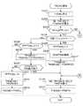
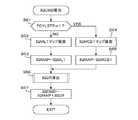
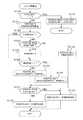
図5は、一部の気筒を休止させる気筒休止(一部気筒運転)の実行条件を判定する処理のフローチャートである。この処理はECU5のメインマイコン53で所定時間(例えば10ミリ秒)毎に実行される。
ステップS211では、始動モードフラグFSTMODが「1」であるか否かを判別し、FSTMOD=1であってエンジン1の始動(クランキング)中であるときは、検出したエンジン水温TWを始動モード水温TWSTMODとして記憶する(ステップS213)。次いで、始動モード水温TWSTMODに応じて図6に示すTMTWCSDLYテーブルを検索し、遅延時間TMTWCSDLYを算出する。TMTWCSDLYテーブルは、始動モード水温TWSTMODが第1所定水温TW1(例えば40℃)以下の範囲では、遅延時間TMTWCSDLYが所定遅延時間TDLY1(例えば250秒)に設定され、始動モード水温TWSTMODが第1所定水温TW1(例えば40℃)より高く第2所定水温TW2(例えば60℃)以下の範囲では、始動モード水温TWSTMODが高くなるほど遅延時間TMTWCSDLYが減少するように設定され、始動モード水温TWSTMODが第2所定水温TW2より高い範囲では、遅延時間TMTWCSDLYは「0」に設定されている。
【0032】
続くステップS215では、ダウンカウントタイマTCSWAITを遅延時間TMTWCSDLYに設定してスタートさせ、気筒休止フラグFCYLSTPを「0」に設定する(ステップS225)。これは気筒休止の実行条件が不成立であることを示す。
【0033】
ステップS211でFSTMOD=0であって通常運転モードであるときは、エンジン水温TWが気筒休止判定温度TWCSTP(例えば75℃)より高いか否かを判別する(ステップS212)。TW≦TWCSTPであるときは、実行条件不成立と判定し、前記ステップS214に進む。エンジン水温TWが気筒休止判定温度TWCSTPより高いときは、ステップS212からステップS216に進み、ステップS215でスタートしたタイマTCSWAITの値が「0」であるか否かを判別する。TCSWAIT>0である間は、前記ステップS24に進み、TCSWAIT=0となると、ステップS217に進む。
【0034】
ステップS217では、後述する図19及び図20の処理により算出される遅角係数KIGKNが所定係数値KIGKNCSX(例えば「1.0」であって、オクタン価90程度の燃料に対応する値)以下か否かを判別する。遅角係数KIGKNは、ノッキング判定結果に応じて設定される。より具体的には、ノッキングが発生するときは、遅角係数KIGKNは、増加する方向(遅角方向)に更新され、ノッキングが発生しないときは、遅角係数KIGKNは、減少する方向(進角方向)に更新される。ステップS217の答が否定(NO)であって、ノッキングの発生頻度が高く、点火時期の遅角補正量が大きいときは、一部気筒運転を禁止すべく前記ステップS225に進む。
これにより、作動気筒数の変更に伴うトルクショックと、点火時期の補正に伴うトルク変化とが重なることがなく、トルクショックを効果的に抑制することができる。
【0035】
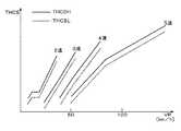
ステップS218では、車速VP及びギヤ位置GPに応じて図7に示すTHCSテーブルを検索し、ステップS219の判別に使用する上側閾値THCSH及び下側閾値THCSLを算出する。図7において、実線が上側閾値THCSHに対応し、破線が下側閾値THCSLに対応する。THCSテーブルは、ギヤ位置GP毎に設定されており、各ギヤ位置(2速〜5速)において、大まかには車速VPが増加するほど、上側閾値THCSH及び下側閾値THCSLが増加するように設定されている。ただし、ギヤ位置GPが2速のときは、車速VPが変化しても上側閾値THCSH及び下側閾値THCSLは一定に維持される領域が設けられている。またギヤ位置GPが1速のときは、常に全筒運転を行うので、上側閾値THCSH及び下側閾値THCSLは例えば「0」に設定される。また車速VPが同一であれば、低速側ギヤ位置GPに対応する閾値(THCSH,THCSL)の方が、高速側ギヤ位置GPに対応する閾値(THCSH,THCSL)より大きな値に設定されている。
【0036】
ステップS219では、スロットル弁開度THが閾値THCSより小さいか否かの判別をヒステリシスを伴って行う。具体的には、気筒休止フラグFCYLSTPが「1」であるときは、スロットル弁開度THが増加して上側閾値THCSHに達すると、ステップS219の答が否定(NO)となり、気筒休止フラグFCYLSTPが「0」であるときは、スロットル弁開度THが減少して下側閾値THCSLを下回ると、ステップS219の答が肯定(YES)となる。
【0037】
ステップS219の答が肯定(YES)であるときは、大気圧PAが所定圧PACS(例えば86.6kPa(650mmHg))以上であるか否かを判別し(ステップS220)、その答が肯定(YES)であるとき、吸気温TAが所定下限温度TACSL(例えば−10℃)以上であるか否かを判別し(ステップS221)、その答が肯定(YES)であるときは、吸気温TAが所定上限温度TACSH(例えば45℃)より低いか否かを判別し(ステップS222)、その答が肯定(YES)であるときは、エンジン回転数NEが所定回転数NECSより低いか否かを判別する(ステップS223)。ステップS223の判別は、ステップS219と同様にヒステリシスを伴って行われる。すなわち、気筒休止フラグFCYLSTPが「1」であるときは、エンジン回転数NEが増加して上側回転数NECSH(例えば3500rpm)に達すると、ステップS223の答が否定(NO)となり、気筒休止フラグFCYLSTPが「0」であるときは、エンジン回転数NEが減少して下側回転数NECSL(例えば3300rpm)を下回ると、ステップS223の答が肯定(YES)となる。
【0038】
ステップS219〜S223の何れかの答が否定(NO)であるときは、気筒休止の実行条件が不成立と判定し、前記ステップS225に進む。一方ステップS219〜S223の答がすべて肯定(YES)であるときは、気筒休止の実行条件が成立していると判定し、気筒休止フラグFCYLSTPを「1」に設定する(ステップS224)。
【0039】
気筒休止フラグFCYLSTPが「1」に設定されているときは、#1〜#3気筒を休止させ、#4〜#6気筒を作動させる一部気筒運転が実行され、気筒休止フラグFCYLSTPが「0」に設定されているときは、全気筒#1〜#6を作動させる全筒運転が実行される。
【0040】
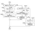
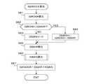
図8及び図9は、スロットル弁の目標開度THCMDを算出する処理のフローチャートである。この処理は、ECU5のメインマイコン53で所定時間(例えば10ミリ秒)毎に実行される。
ステップS231では、アクセルペダル操作量APに応じて基本目標開度THONLを算出する。基本目標開度THONLは、アクセルペダル操作量APにほぼ比例するように設定される。ステップS232では、エンジン回転数NE及びスロットル弁開度THに応じてTRQBASEマップ(図示せず)を検索し、エンジン1の基本目標トルクTRQASEを算出する。TRQBASEマップは、エンジン回転数NE及びスロットル弁開度THを変化させて、全筒運転時のエンジン1の出力トルクを測定することにより、予め設定されている。
【0041】
ステップS233では、気筒休止フラグFCYLSTPが「0」であるか否かを判別する。FCYLSTP=0であって全筒運転中であるときは、気筒休止フラグFCYLSTPが前回「1」であったか否かを判別する(ステップS234)。この答が肯定(YES)、すなわち一部気筒運転から全筒運転への移行直後であるときは、第1移行フラグFPTTOALを「1」に設定する(ステップS235)。次いでエンジン回転数NE及び吸気管内絶対圧PBAに応じてDCSTRQDマップを検索し、減算補正項DCSTRQDを算出する(ステップS236)。DCSTRQDマップは、エンジン回転数NEが高くなるほど、また吸気管内絶対圧PBAが高くなるほど、減算補正項DCSTRQDが大きくなるように設定されている。
【0042】
ステップS237では、下記式に基本目標トルクTRQBASE及び減算補正項DCSTRQDを適用して、目標トルクTRQENGを算出する。
TRQENG=TRQBASE−DCSTRQD
続くステップS260では、エンジン回転数NE及び目標トルクTRQENGに応じて全筒運転用のTRQTHマップ(図示せず)を検索し、目標トルクTRQENGを出力するのに必要な要求スロットル弁開度TRQTHを算出する。全筒運転用のTRQTHマップは、ステップS232で検索されるTRQBASEマップと実質的の同一内容のマップである。すなわち、TRQBASEマップは、エンジン回転数NE及びスロットル弁開度THから基本目標トルクTRQBASEを算出するように設定されており、全筒運転用のTRQTHマップは、エンジン回転数NE及び目標トルクTRQENGから、要求スロットル弁開度TRQTHを算出するように設定されている。
ステップS261では、目標開度THCMDを、ステップS260で算出した要求スロットル弁開度TRQTHに設定する。
【0043】
ステップS234の答が否定(NO)、すなわち前回以前から全筒運転が行われているときは、第1移行フラグFPTTOALが「1」であるか否かを判別する(ステップS238)。最初はFPTTOAL=1であるので、ステップS239に進み、下記式により目標トルクTRQENGを漸増させる。
TRQENG=TRQENG+DTRQENGD
ここで、DTRQENGDは、所定加算値である。
【0044】
ステップS240では、目標トルクTRQENGが基本目標トルクTRQBASEより小さいか否かを判別し、TRQENG<TRQBASEであるときは、前記ステップS260に進む。ステップS260では、全筒運転用のTRQTHマップを用いて要求スロットル弁開度TRQTHが算出される。目標トルクTRQENGが基本目標トルクTRQBASE以上であるときは、ステップS241に進み、第1移行フラグFPTTOALを「0」に設定する。次いで、目標トルクTRQENGを基本目標トルクTRQBASEに設定する(ステップS242)とともに、目標開度THCMDを基本目標開度THONLに設定する(ステップS243)。
ステップS241で第1移行フラグFPTTOALが「0」に設定されると、その後は、ステップS238から直ちにステップS241に進む。
【0045】
ステップS233でFCYLSTP=1であって一部気筒運転中であるときは、気筒休止フラグFCYLSTPが前回「0」であったか否かを判別する(ステップS251)。この答が肯定(YES)、すなわち全気筒運転から一部気筒運転への移行直後であるときは、第2移行フラグFALTOPTを「1」に設定する(ステップS252)。次いでエンジン回転数NE及び吸気管内絶対圧PBAに応じてDCSTRQUマップを検索し、加算補正項DCSTRQUを算出する(ステップS253)。DCSTRQUマップは、エンジン回転数NEが高くなるほど、また吸気管内絶対圧PBAが高くなるほど、加算補正項DCSTRQUが大きくなるように設定されている。
【0046】
ステップS254では、下記式に基本目標トルクTRQBASE及び加算補正項DCSTRQUを適用して、目標トルクTRQENGを算出する。
TRQENG=TRQBASE+DCSTRQU
ステップS254実行後は、前記ステップS260に進む。ステップS260では、エンジン回転数NE及び要求トルクTRQENGに応じて、一部気筒運転用のTRQTHマップ(図示せず)を検索し、要求スロットル弁開度TRQTHが算出される。一部気筒運転用のTRQTHマップは、エンジン回転数NE及び目標トルクTRQENGに対応する、一部気筒運転時の要求スロットル弁開度TRQTHが設定されている。
【0047】
ステップS251の答が否定(NO)、すなわち前回以前から一部気筒運転が行われているときは、第2移行フラグFALTOPTが「1」であるか否かを判別する(ステップS255)。最初はFALTOPT=1であるので、ステップS256に進み、下記式により目標トルクTRQENGを漸減させる。
TRQENG=TRQENG−DTRQENGD
【0048】
ステップS257では、目標トルクTRQENGが基本目標トルクTRQBASEより大きいか否かを判別し、TRQENG>TRQBASEであるときは、前記ステップS260に進む。目標トルクTRQENGが基本目標トルクTRQBASE以下であるときは、ステップS258に進み、第2移行フラグFALTOPTを「0」に設定する。次いで、目標トルクTRQENGを基本目標トルクTRQBASEに設定し(ステップS259)、前記ステップS260に進む。ステップS260では、一部気筒運転用のTRQTHマップを検索することにより、要求スロットル弁開度TRQTHが算出される。
【0049】
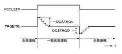
図8及び図9の処理によれば、図10に示すように、全筒運転から一部気筒運転への移行(FCYLSTP=0→1)直後は、目標トルクTRQENGはステップ状に増加し、その後基本目標トルクTRQBASEまで漸減する。また一部気筒運転から全筒運転への移行(FCYLSTP=1→0)直後は、目標トルクTRQENGはステップ状に減少し、その後基本目標トルクTRQBASEまで漸増する。そして、スロットル弁の目標開度THCMDが、この目標トルクTRQENGに応じて設定され、実際のエンジン1の出力トルクが目標トルクTRQENGとなるようにスロットル弁開度が制御される。これにより、作動気筒数の変更に伴うトルクショックを抑制することができる。
【0050】
なお、基本目標開度THONLは、図示しない変速制御処理あるいはトラクション制御処理においても用いられる。トラクション制御においては、当該車両の駆動輪の過剰スリップ状態が検出され、過剰スリップを抑制するように、エンジン1の出力トルクが制限される。
【0051】
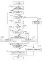
図11は、メインマイコン53で実行されるノッキング判定処理のフローチャートである。この処理は、TDCパルスの発生に同期して実行される。
ステップS11では、下記式(1)によりノイズレベルNZMINAA(n)を算出する。
NZMINAA(n)=(NZMINAA(n−3)+NZMINAA(n−2)+NZMINAA(n−1)+NZMIN(n))/4 (1)
【0052】
ここで、右辺のNZMINAA(n−3)〜NZMINAA(n−1)は、ノイズレベルの過去値であり、NZMIN(n)は、サブマイコン52から送信される最新の検出最小値である。
【0053】
ステップS12では、図12に示すGAMP算出処理を実行し、ゲイン係数GAMPを算出する。
【0054】
図12のステップS31では、気筒休止フラグFCYLSTPが「1」であるか否かを判別する。ステップS31の答が否定(NO)であって、全筒運転中であるときは、エンジン回転数NE及び吸気管内絶対圧PBAに応じてAMPGL1マップ(図示せず)を検索し、第1マップ値AMPGL1を算出する(ステップS34)。AMPGL1マップは、エンジン回転数NEが増加するほど、また吸気管内絶対圧PBAが増加するほど、第1マップ値AMPGL1が増加するように設定されている。続くステップS35では、ゲイン係数GAMPを第1マップ値AMPGL1に設定して、本処理を終了する。
【0055】
一方、ステップS31の答が肯定(YES)であって、一部気筒運転中であるときは、エンジン回転数NE及び吸気管内絶対圧PBAに応じてAMPGCSマップ(図示せず)を検索し、第2マップ値AMPGCSを算出する(ステップS32)。AMPGCSマップは、エンジン回転数NEが増加するほど、また吸気管内絶対圧PBAが増加するほど、第2マップ値AMPGCSが増加するように設定されている。また同一のエンジン回転数NE及び吸気管内絶対圧PBAにおいては、第2マップ値AMPGCSは、第1マップ値AMPGL1より小さな値に設定されている。
【0056】
続くステップS33では、ゲイン係数GAMPを第2マップ値AMPGCSに設定して、本処理を終了する。
【0057】
図11に戻り、ステップS13では、図13に示すKAGTW算出処理を実行し、補正係数KAGTWを算出する。
【0058】
図13のステップS41では、エンジン水温TWが第3所定水温TWKAG2(例えば70℃)以下か否かを判別し、TW>TWKAG2であるときは、補正係数KAGTWを「1.0」(無補正値)に設定する(ステップS50)。
ステップS41でTW≦TWKAG2であるときは、エンジン水温TWが第3所定水温TWKAG2より低い第2所定水温TWKAG1(例えば60℃)以下か否かを判別する(ステップS42)。ステップS42の答が否定(NO)、すなわちTWKAG1<TW≦TWKAG2であるときは、エンジン回転数NEに応じて図14に示すKAGTW2テーブル(実線L13)を検索し、第3係数値KAGTW2を算出する(ステップS48)。KAGTW2テーブルは、エンジン回転数NEが増加するほど、第3係数値KAGTW2が増加するように設定されている。次いで、補正係数KAGTWをその第3係数値KAGTW2に設定する(ステップS49)。
【0059】
ステップS42で、TW≦TWKAG1であるときは、エンジン水温TWが第2所定水温TWKAG1より低い第1所定水温TWKAG0(例えば40℃)以下か否かを判別する(ステップS43)。ステップS43の答が否定(NO)、すなわちTWKAG0<TW≦TWKAG1であるときは、エンジン回転数NEに応じて図14に示すKAGTW1テーブル(破線L12)を検索し、第2係数値KAGTW1を算出する(ステップS46)。KAGTW1テーブルは、エンジン回転数NEが増加するほど、第2係数値KAGTW2が増加するように設定されている。次いで、補正係数KAGTWをその第2係数値KAGTW1に設定する(ステップS47)。
【0060】
ステップS43でTW≦TWKAG0であるときは、エンジン回転数NEに応じて図14に示すKAGTW0テーブル(実線L11)を検索し、第1係数値KAGTW0を算出する(ステップS44)。KAGTW0テーブルは、エンジン回転数NEが増加するほど、第1係数値KAGTW0が増加するように設定されている。次いで、補正係数KAGTWをその第1係数値KAGTW0に設定する(ステップS45)。
【0061】
図13の処理によれば、補正係数KAGTWは、エンジン水温TWが低下するほど増加するように、またエンジン回転数NEが増加するほど増加するように設定される。
【0062】
図11に戻り、ステップS14では、エンジン回転数NEがゲイン切換回転数NEKIRI(例えば2500rpm)より高いか否かを判別する。NE>NEKIRIであってエンジン1が高回転で運転されているときは、ゲイン切換回路62のゲインを低ゲインとする制御信号を出力する(ステップS15)とともに、ゲイン切換係数KAGKIRIを高回転用所定値KAGKIRIHに設定する(ステップS16)。一方、ステップS14でNE≦NEKIRIであるときは、ゲイン切換回路62のゲインを高ゲインとする制御信号を出力する(ステップS17)とともに、ゲイン切換係数KAGKIRIを低回転用所定値KAGKIRILに設定する(ステップS16)。低回転用所定値KAGKIRILは、高回転用所定値KAGKIRIHより大きな値に設定されている。
ステップS19では、ノイズレベルNZMINAA、ゲイン係数GAMP、補正係数KAGTW及びゲイン切換係数KAGKIRIを下記式(2)に適用し、判定閾値KLVLを算出する。
KLVL=NZMINAA×GAMP×KAGTW×KAGKIRI (2)
【0063】
ステップS20では、ノックレベルの最大値KSMAXが判定閾値KLVLを超えたか否かを判別し、KSMAX>KLVLであるときは、ノッキング発生と判定して、ノッキングフラグFKNOCKを「1」に設定する(ステップS21)。一方、KSMAX≦KLVLであるときは、ノッキングは発生していないと判定し、ノッキングフラグFKNOCKを「0」に設定する(ステップS22)。
【0064】
次に本実施形態における点火時期制御の概要を、図15を参照して説明する。図15のラインL21は、エンジン1の出力トルクを最大とするMBT(Minimum Spark Advance for Best Torque)を示し、ラインL22は、高オクタン価(例えばオクタン価100)燃料のノック限界点火時期IGRONHを示し、ラインL23は、低オクタン価(例えばオクタン価90)燃料のノック限界点火時期IGRONLを示す。なお、点火時期は、上死点からの進角量で示される。
【0065】
本実施形態では、高オクタン価燃料を基準とした基本点火時期IGMAPが、エンジン回転数NE及び吸気管内絶対圧PBAに応じたマップに設定されている。
より具体的には、基本点火時期IGMAPは、図15に破線で示すように、吸気管内絶対圧PBAが図15の点PXに対応する所定吸気圧PBPXより低い低負荷運転状態では、ラインL21に対応するMBTが設定され、吸気管内絶対圧PBAが所定吸気圧PBPXより高い高負荷運転状態では、ラインL22に対応するノック限界点火時期IGRONHが設定されている。
【0066】
そして点火時期IGCMDは、下記式(3)により算出される。
IGCMD=IGMAP+IGCR (3)
ここで、IGCRは、下記式(4)により算出される補正項である。
IGCR=DIGRSV+IGTW+IGPA−IGTA−IGKNOCK(4)
DIGRSVは、図15に示すように、点PXより低負荷側で(IGRONH−MBT)に設定され、点PXより高負荷側では「0」に設定される低負荷進角補正項である。IGTWはエンジン水温TWに応じて設定される水温補正項であり、IGPAは大気圧に応じて設定される大気圧補正項であり、IGTAは、吸気温TAに応じて設定される吸気温補正項である。また、IGKNOCKは、下記式(5)により算出されるノック補正項である。
IGKNOCK=DIGKR×KIGKN (5)
【0067】
ここでDIGKRは、図15に示すように、高オクタン価燃料のノック限界点火時期IGRONHと、低オクタン価燃料のノック限界点火時期IGRONLとの差(以下「オクタン価差分項」という)であり、KIGKNは、ノッキング判定結果に応じて設定される遅角係数である。ノッキングが発生するときは、遅角係数KIGKNは、増加する方向(遅角方向)に更新され、ノッキングが発生しないときは、遅角係数KIGKNは、減少する方向(進角方向)に更新される。
【0068】
図16は、点火時期IGCMDを算出する処理のフローチャートである。この処理は、メインマイコン53により、TDCパルスの発生に同期して実行される。
ステップS61では、気筒休止フラグFCYLSTPが「1」であるか否かを判別する。ステップS61の答が否定(NO)であって、全筒運転中であるときは、エンジン回転数NE及び吸気管内絶対圧PBAに応じてIGML1マップ(図示せず)を検索し、第1マップ値IGML1を算出する(ステップS62)。IGML1マップは、全筒運転用の基本点火時期マップであり、上述したよに、吸気管内絶対圧PBAが図15の点PXに対応する所定吸気圧PBPXより低い低負荷運転状態では、ラインL21に対応するMBTが設定され、吸気管内絶対圧PBAが所定吸気圧PBPXより高い高負荷運転状態では、ラインL22に対応するノック限界点火時期IGRONHが設定されている。続くステップS63では、基本点火時期IGMAPを第1マップ値IGML1に設定して、ステップS66に進む。
【0069】
一方、ステップS61の答が肯定(YES)であって、一部気筒運転中であるときは、エンジン回転数NE及び吸気管内絶対圧PBAに応じてIGMCS1マップ(図示せず)を検索し、第2マップ値IGMCS1を算出する(ステップS64)。IGMCS1マップは、一部気筒運転用の基本点火時期マップであり、上述したように、吸気管内絶対圧PBAが図15の点PXに対応する所定吸気圧PBPXより低い低負荷運転状態では、ラインL21に対応するMBTが設定され、吸気管内絶対圧PBAが所定吸気圧PBPXより高い高負荷運転状態では、ラインL22に対応するノック限界点火時期IGRONHが設定されている。
【0070】
基本点火時期マップとして、全筒運転用マップと一部気筒運転用マップとを設けるのは、全筒運転におけるエンジンの体積効率(吸入効率)ηVと、一部気筒運転における体積効率ηVとが異なるからである。
続くステップS65では、基本点火時期IGMAPを、第2マップ値IGMCS1に設定して、ステップS66に進む。
【0071】
ステップS66では、図17に示すIGCR算出処理を実行し、補正項IGCRを算出する。ステップS67では、前記式(3)により、点火時期IGCMDを算出する。
【0072】
図17は、図16のステップS66で実行されるIGCR算出処理のフローチャートである。
ステップS71では、図18に示すIGKNOCK算出処理を実行し、ノック補正項IGKNOCKを算出する。ステップS72では、エンジン水温TWに応じて水温補正項IGTWを算出し、ステップS73では、吸気温TAに応じて吸気温補正項IGTAを算出する。さらにステップS74では、大気圧PAに応じて大気圧補正項IGPAを算出する。
ステップS75では、前記式(4)により、補正項IGCRを算出する。
【0073】
図18は、図17のステップS71で実行されるIGKNOCK算出処理のフローチャートである。
ステップS81では、エンジン回転数NE及び吸気管内絶対圧PBAに応じてIGRONHマップ(図示せず)を検索し、高オクタン価燃料のノック限界点火時期IGRONHを算出する。そして、ノック限界点火時期IGRONHが基本点火時期IGMAPより大きいか否かを判別し(ステップS82)、IGRONH≦IGMAPであるときは、低負荷進角補正項DIGRSVを「0」に設定する(ステップS83)。一方、IGRONH>IGMAPであるときは、下記式(6)により、低負荷進角補正項DIGRSVを算出する(ステップS84)。
DIGRSV=IGRONH−IGMAP (6)
【0074】
ステップS85では、エンジン回転数NE及び吸気管内絶対圧PBAに応じてDIGKRマップ(図示せず)を検索し、オクタン価差分項DIGKRを算出する。DIGKRマップは、図15に示すように、高オクタン価燃料のノック限界点火時期IGRONHと、低オクタン価燃料のノック限界点火時期IGRONLとの差分が、エンジン回転数NE及び吸気管内絶対圧PBAに対応して設定されている。
【0075】
ステップS86では、図19及び図20に示すKIGKN算出処理を実行し、遅角係数KIGKNを算出する。ステップS87では、前記式(5)により、ノック補正項IGKNOCKを算出する。
【0076】
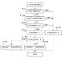
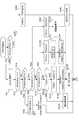
図19及び図20は、図18のステップS86で実行されるKIGKN算出処理のフローチャートである。
ステップS91では、図21に示すリミット値算出処理を実行し、遅角係数KIGKNの上限値KIGKNLMH及び下限値KIGKNLMLを算出する。ステップS92では、異常検出フラグFFSPKSが「1」であるか否かを判別する。異常検出フラグFFSPKSは、吸気管内絶対圧センサ7,吸気温センサ8などのエンジン運転状態を検出する各種センサのいずれかの故障が検出されたとき「1」に設定される。FFSPKS=1であって、フェールセーフ動作が必要であるときは、遅角係数KIGKNをフェールセーフ用所定値FSKIGKNに設定し(ステップS93)、第2リミット処理を実行する(ステップS94)。第2リミット処理では、遅角係数KIGKNが上限値KIGKNLMHを超えているときは、その上限値IGKNLMHに再設定される。ステップS94を実行した後、ステップS110に進む。
【0077】
ステップS92でFFSPKS=0であってフェールセーフ動作が不要であるときは、初期フラグFKIGKNINIが「1」であるか否かを判別する(ステップS95)。最初は、FKIGKNINI=0であるので、ステップS96に進み、初期フラグFKIGKNINIを「1」に設定する。次いで、下記式(7)により、遅角係数KIGKNを算出する(ステップS97)。
KIGKN=KIGKREF+DKNINI (7)
【0078】
ここで、KIGKREFは、後述する学習値算出処理で算出される、遅角係数KIGKNの第1学習値であり、DKNINIは、所定の初期設定加算値である。
ステップS97の実行後は、ステップS109に進む。
【0079】
ステップS96で初期フラグFKIGKNINIが「1」に設定されると、ステップS95からステップS98に進み、ノック判定禁止フラグFKNOCKPが「1」であるか否かを判別する。ノック判定禁止フラグFKNOCKPは、エンジン回転数NEが低い(例えば1000rpm未満の)ときやエンジンへの燃料供給を停止するフュエルカット中などにおいて「1」に設定される。ステップS98の答が肯定(YES)であるときは、ダウンカウントタイマTADVを第1所定時間TMADVS(例えば0.2秒)に設定してスタートさせる(ステップS99)。次いで、遅角係数KIGKNを前回値と同一の設定として(ステップS100)、ステップS109に進む。
【0080】
ステップS98でFKNOCKP=0であるときは、ノッキングフラグFKNOCKが「1」であるか否かを判別する(ステップS101)。FKNOCK=1であってノッキングが発生したときは、ダウンカウントタイマTADVを第2所定時間TMADVL(例えば0.5秒)に設定してスタートさせる(ステップS102)。次いで、加算項DKIGKNUを所定値DKIGKNUSに設定し(ステップS103)、その加算項DKIGKNUを下記式(8)に適用して、遅角係数KIGKNを増加方向に更新する(ステップS104)。これにより、点火時期の遅角補正量が増加する。
KIGKN=KIGKN+DKIGKNU (8)
ステップS104実行後は、ステップS109に進む。
【0081】
ステップS101でFKNOCK=0であるときは、ステップS99またはステップS102でスタートされるダウンカウントタイマTADVの値が「0」であるか否かを判別する(ステップS105)。この答が否定(NO)である間は、遅角係数KIGKNを前回値と同一の設定として(ステップS106)、ステップS109に進む。タイマTADVの値が「0」となると、ステップS105からステップS107に進み、該タイマTADVを第1所定時間TMADVSに設定してスタートさせる。次いで、下記式(9)により、遅角係数KIGKNを減少方向に更新し(ステップS108)、ステップS109に進む。式(9)による更新によって、点火時期の遅角補正量が減少する(点火時期は進角方向に変化する)。
KIGKN=KIGKN−DKIGKND (9)
ここで、DKIGKNDは、所定減算値である。
【0082】
ステップS109では、算出された遅角係数KIGKNの第1リミット処理を実行する。すなわち、遅角係数KIGKNが、ステップS91で算出される上限値KIGKNLMHを超えるときは、その上限値KIGKNLMHに再設定され、遅角係数KIGKNがステップS91で算出される下限値KIGKNLMLより小さいときは、その下限値KIGKNLMLに再設定される。
【0083】
ステップS110では、学習値算出用遅角係数KIGKMを、算出された遅角係数KIGKNに設定し、次いで図23及び図24に示す学習値算出処理を実行する(ステップS111)。この学習値算出処理により、全筒運転に対応して第1学習値KIGKREF及び第2学習値KIGKREFEが算出され、一部気筒運転に対応して第3学習値KIGKRFCSが算出される。第1学習値KIGKREFは、排気還流を行わない運転状態に対応して算出される学習値であり、第2学習値KIGKREFEは、排気還流を行う運転状態に対応して算出される学習値である。
【0084】
ステップS112では、学習値算出処理で設定される進角学習フラグFKIGKNADVが「1」であるか否かを判別する。進角学習フラグFKIGKNADVは、学習値が進角方向に更新されたとき「1」に設定される。
ステップS112の答が否定(NO)であるときは、遅角係数KIGKNを、学習値算出用遅角係数KIGKMに設定する(ステップS113)。ステップS112でFKIGKNADV=1であって学習値が進角方向に更新されたときは、気筒休止フラグFCYLSTPが「1」であるか否かを判別する(ステップS114)。そしてFCYLSTP=1であって一部気筒運転中であるときは、遅角係数KIGKNを第3学習値KIGKRFCSに設定する(ステップS115)。
【0085】
ステップS114でFCYLSTP=0であって全筒運転中であるときは、EGRフラグFEGRMが「1」であるか否かを判別する(ステップS116)。EGRフラグFEGRMは、排気還流を実行しているとき「1」に設定される。FEGRM=1であるときは、遅角係数KIGKNを第2学習値KIGKREFEに設定し(ステップS117)、FEGRM=0であるときは、遅角係数KIGKNを第1学習値KIGKREFに設定する(ステップS118)。
【0086】
図21は、図19のステップS91で実行されるリミット値算出処理のフローチャートである。
ステップS121では、エンジン水温TWに応じて図22に示すKIGKNLMXテーブルを検索し、リミット値KIGLNLMXを算出する。KIGKNLMXテーブルは、エンジン水温TWが増加するほど、リミット値KIGKNLMXが増加するように設定されている。エンジン水温TWが低いときは、ノッキングは発生せず、エンジン水温TWが高くなるほど発生しやすくなることを考慮したものである。
【0087】
ステップS122では、制御モードフラグFKNFBが「1」であるか否かを判別する。制御モードフラグFKNFBは、初期値は「0」であり、ステップS123の答が肯定(YES)となると、ステップS125で「1」に設定される。最初は、FKNFB=0であるので、ステップS123に進み、ステップS121で算出されたリミット値KIGKNLMXが第1学習値KIGKREF以上であるか否かを判別する。エンジンの始動直後は、ステップS123の答は否定(NO)となるので、ステップS124に進み、下限値KIGKNLMLをリミット値KIGKNLMXに設定する。次いで、上限値KIGKNLMHもリミット値KIGKNLMXに設定する(ステップS133)。
【0088】
ステップS123の答が肯定(YES)となると、制御モードフラグFKNFBを「1」に設定し(ステップS125)、ステップS126に進む。制御モードフラグFKNFBが「1」に設定された後は、ステップS122から直ちにステップS126に進む。
【0089】
ステップS126では、気筒休止フラグFCYLSTPが「1」であるか否かを判別し、FCYLSTP=1であるときは、下限値KIGKNLMLを、第3学習値KIGKRFCS及び所定下限値KIGKNLのうち、いずれか大きい方に設定する(ステップS127)。FCYLSTP=0であるときは、EGRフラグFEGRMが「1」であるか否かを判別し(ステップS128)、FEGRM=1であるときは、下限値KIGKNLMLを、第2学習値KIGKREFE及び所定下限値KIGKNLのうち、いずれか大きい方に設定する(ステップS130)。また、FEGRM=0であるときは、下限値KIGKNLMLを、第1学習値KIGKREF及び所定下限値KIGKNLのうち、いずれか大きい方に設定する(ステップS129)。
【0090】
ステップS131では、ステップS121で算出されたリミット値KIGKNLMXが下限値KIGKNLML以上であるか否かを判別し、その答が肯定(YES)であるときは、前記ステップS133に進んで、上限値KIGKNLMHをリミット値KIGKNLMXに設定する。ステップS131の答が否定(NO)であるときは、上限値KIGKNLMHを下限値KIGKNLMLと等しくする(ステップS132)。
【0091】
図23及び図24は、図20のステップS111で実行される学習値算出処理のフローチャートである。
ステップS140では、初期化フラグFKNREFMODが「1」であるか否かを判別する。最初はFKNREFMOD=0であるので、ステップS141に進み、異常検出フラグFFSPKSが「1」であるか否かを判別する。この答が否定(NO)であってセンサの異常が検出されていないときは、直ちにステップS143に進む。一方、FFSPKS=1であって何れかのセンサの異常が検出されているときは、学習値算出用の中間パラメータKIGKNREF、第1学習値KIGKREF、第2学習値KIGKREFE及び第3学習値KIGKRFCSをいずれも初期化所定値KIGRINIに設定する(ステップS142)。
【0092】
ステップS143では、初期化フラグFKNREFMODを「1」に設定する。次いで、進角補正項DRREFを「0」に設定し(ステップS144)、ダウンカウントタイマTDRREFを所定時間TDREF0(例えば1.0秒)に設定してスタートさせる(ステップS145)。さらにステップS173に進んで、進角学習フラグFKIGKNADVを「0」に設定する。
【0093】
初期化フラグFKNREFMODが「1」に設定されると、ステップS141からステップS146に進み、気筒休止フラグFCYLSTPが「1」であるか否かを判別する。FCYLSTP=1であって一部気筒運転中であるときは、中間パラメータKIGKNREFを第3学習値KIGKRFCSに設定する(ステップS147)。FCYLSTP=0であって全筒運転中であるときは、EGRフラグFEGRMが「1」であるか否かを判別する(ステップS148)。FEGRM=1であって排気還流実行中であるときは、中間パラメータKIGKNREFを第2学習値KIGKREFEに設定する(ステップS149)。FEGRM=0であって排気還流を実行していないときは、中間パラメータKIGKNREFを第1学習値KIGKREFに設定する(ステップS150)。
【0094】
続くステップS151では、ノッキングフラグFKNOCKが「1」であるか否かを判別し、FKNOCK=1であってノッキングが発生したときは、下記式(10)により、進角補正項DRREFを所定値DDRREFだけデクリメントする(ステップS152)。
DRREF=DRREF−DDRREF (10)
【0095】
ステップS153では、進角補正項DRREFのリミット処理を行う。すなわち、進角補正項DRREFが所定下限値DRREFLより小さいときは、進角補正項DRREFは、その所定下限値DRREFLに再設定される。その後ステップS154に進む。
【0096】
ステップS151でFKNOCK=0であってノッキングが発生していない時は、直ちにステップS154に進む。
ステップS154では、学習値算出用遅角係数KIGKMが中間パラメータKIGKNREF以下であるか否かを判別し、KIGKM>KIGKNREFであって、遅角係数KIGKMが中間パラメータKIGKNREFより遅角側の値であるときは、ステップS155〜S159により、学習値算出用遅角係数KIGKMをなまし処理することにより、各学習値が算出されるとともに、算出された学習値の上限リミット処理が行われる。学習値算出用遅角係数KIGKMは図19のステップS109でリミット処理がなされているが、学習値の上限値は別に設定される場合があるため、再度リミット処理が行われる。
【0097】
ステップS155では、気筒休止フラグFCYLSTPが「1」であるか否かを判別する。FCYLSTP=1であって一部気筒運転中であるときは、下記式(11)に、学習値算出用遅角係数KIGKMを適用して、第3学習値KIGKRFCSを算出する(ステップS156)。この演算の結果、第3学習値KIGKRFCSが所定上限値KIGREFHを超えたときは、第3学習値KIGKRFCSはこの所定上限値KIGREFHに再設定される。
KIGKRFCS=CKIGREF×KIGKM+(1−CKIGREF)×KIGKRFCS (11)
ここでCKIGREFは0から1の間の値に設定されるなまし係数であり、右辺のKIGKRFCSは、第3学習値の最新の過去値である。
【0098】
ステップS155でFCYLSTP=0であって全筒運転中であるときは、EGRフラグFEGRMが「1」であるか否かを判別する(ステップS157)。FEGRM=1であって排気還流実行中であるときは、下記式(12)により第2学習値KIGKREFEを算出する(ステップS158)。この演算の結果、第2学習値KIGKREFEが所定上限値KIGREFHを超えたときは、第2学習値KIGKREFEはこの所定上限値KIGREFHに再設定される。
KIGKREFE=CKIGREF×KIGKM+(1−CKIGREF)×KIGKREFE (12)
ここで右辺のKIGKREFEは、第2学習値の最新の過去値である。
【0099】
またFEGRM=0であって排気還流を実行していないときは、下記式(13)により、第1学習値KIGKREFを算出する(ステップS159)。この演算の結果、第2学習値KIGKREFEが所定上限値KIGREFHを超えたときは、第2学習値KIGKREFEはこの所定上限値KIGREFHに再設定される。
KIGKREF=CKIGREF×KIGKM+(1−CKIGREF)×KIGKREF (13)
ここで右辺のKIGKREFは、第1学習値の最新の過去値である。
続くステップS160では、進角学習フラグFKIGKNADVを「0」に設定し、本処理を終了する。
【0100】
ステップS154でKIGKM≦KIGKNREFであって、学習値算出用遅角係数KIGKMが中間パラメータKIGKNREFより進角側の値であるときは、ステップS145でスタートされたダウンカウントタイマTDRREFの値が「0」であるか否かを判別する(ステップS161)。そしてTDRREF>0である間は前記ステップS173に進み、TDRREF=0となると、図25に示すFADVREF設定処理を実行する(ステップS162)。
【0101】
図25のステップS181では、エンジン水温TWが所定水温TWRMH(例えば120℃)より高いか否かを判別し、TW≦TWRMHであるときは、燃料噴射量の高負荷補正係数KWOTが所定計数値KWOTKN(例えば1.438)より大きいか否かを判別する。高負荷補正係数KWOTは、スロットル弁がほぼ全開とされるスロットル全開運転状態において「1.0」より大きな値に設定され、それ以外のエンジン運転状態では「1.0」に設定される。
【0102】
ステップS182の答が否定(NO)、すなわちスロットル全開運転状態でないときは、ダウンカウントタイマTKAGNGUの値が「0」であるか否かを判別する(ステップS183)。ダウンカウントタイマTKAGNGUは、エンジンへの燃料供給を遮断するフュエルカット運転を終了した時点(燃料供給を再開した時点)において所定時間TFCD(例えば0.5秒)に設定される。TKAGNGU=0であってフュエルカット運転終了後所定時間TFCDが経過しているときは、ステップS184に進み、進角学習許可フラグFADVREFを「1」に設定する。
【0103】
次いで気筒休止フラグFCYLSTPが「1」であるか否かを判別し(ステップS186)、FCYLSTP=1であって一部気筒運転中であるときは、ダウンカウントタイマTDRREFを一部気筒運転用所定時間TMDRRFCS(例えば1.0秒)に設定してスタートさせる(ステップS187)。またFCYLSTP=0であって全筒運転中であるときは、ダウンカウントタイマTDRREFを全筒運転用所定時間TMDRREFL(例えば0.4〜1.0秒)に設定してスタートさせる(ステップS188)。
【0104】
ステップS181若しくはS182の答が肯定(YES)、またはステップS183の答が否定(NO)であるときは、ステップS185に進み、進角学習許可フラグFADVREFを「0」に設定する。これにより、進角方向への学習値の更新が禁止される。平均的なエンジン運転状態から大きく外れたエンジン運転状態においては、学習値を進角方向へ更新することは好ましくないからである。
【0105】
図24に戻り、ステップS163では、進角学習許可フラグFADVREFが「1」であるか否かを判別し、FADVREF=0であって進角学習が許可されていないときは、学習値を更新することなく前記ステップS173に進む。
一方FADVREF=1であって進角学習が許可されているときは、下記式(14)により、中間パラメータKIGKNREFを進角補正項DRREFだけデクリメントする(ステップS164)。これにより、中間パラメータKIGKNREFは、進角方向に更新される。
KIGKNREF=KIGKNREF−DRREF (14)
【0106】
ステップS165では、気筒休止フラグFCYLSTPが「1」であるか否かを判別し、FCYLSTP=0であって全筒運転中であるときは、中間パラメータの第1のリミット処理を実行する(ステップS168)。具体的には、中間パラメータKIGKNREFが所定下限値KIGREFLより小さいときは、中間パラメータKIGKNREFは、その所定下限値KIGREFLに再設定される。
【0107】
次いでEGRフラグFEGRMが「1」であるか否かを判別し(ステップS169)、FEGRM=1であって排気還流を実行しているときは、第2学習値KIGKREFEを中間パラメータKIGKNREFに設定して(ステップS170)、ステップS172に進む。またFEGRM=0であって排気還流を実行していないときは、第1学習値KIGKREFを中間パラメータKIGKNREFに設定して(ステップS171)、ステップS172に進む。
【0108】
またステップS165でFCYLSTP=1であって一部気筒運転中であるときは、中間パラメータKIGKNREFの第2のリミット処理を実行する(ステップS166)。具体的には、中間パラメータKIGKNREFが所定下限値KIGRFCLより小さいときは、中間パラメータKIGKNREFは、その所定下限値KIGRFCLに再設定される。
【0109】
続くステップS167では、第3学習値KIGKRFCSを中間パラメータKIGKNREFに設定し、ステップS172に進む。
ステップS172では、進角学習フラグFKIGKNADVを「1」に設定する。
【0110】
図23及び図24の処理によれば、全筒運転においては、第1学習値KIGKREFまたは第2学習値KIGKREFEが算出され、一部気筒運転においては、第3学習値KIGKRFCSが算出されるたので、それぞれの運転状態に適した遅角係数の学習値が得られる。例えば一部気筒運転から全筒運転に、またはその逆に運転状態が移行し、かつ学習値KIGKREF,KIGKREFE、またはKIGKRFCSが進角方向に更新されたときには、移行後の運転状態に適した学習値が、遅角係数KIGKNとして適用される(図20,ステップS114〜S118)。その結果、そのような運転状態の変化直後であってもノッキングの抑制しつつ、十分なエンジン出力を得ることができる。
【0111】
以上のように本実施形態では、図19及び図20の処理により、ノッキングの検出結果に応じて設定される遅角係数KIGKNが、所定係数値KIGKNCSXより大きいとき、すなわちノッキングの発生頻度が高く、点火時期の遅角補正量が大きいときは、一部気筒運転が禁止される(図5,ステップS217参照)。したがって、作動気筒数の変更に伴うトルクショックと、ノッキングの発生による点火時期の補正に伴うトルク変化とが重なることがなく、トルクショックを抑制することができる。
【0112】
本実施形態においては、気筒休止機構30が切換手段に相当し、スロットル弁開度センサ4、吸気温センサ8、エンジン水温センサ9、クランク角度位置センサ10、車速センサ15,及びギヤ位置センサ16が運転パラメータ検出手段を構成する。また、ECU5のアナログ回路部51,サブマイコン52及びメインマイコン53がノッキング検出手段を構成し、メインマイコン53が指令手段、点火時期制御手段、補正手段、及び禁止手段を構成する。より具体的には、図11の処理がノッキング検出手段の一部に相当し、図5の処理が指令手段に相当する。また図16の処理が点火時期制御手段に相当し、図18の処理が補正手段に相当し、図5のステップS217が禁止手段に相当する。
【0113】
(第2の実施形態)
本実施形態は、ノッキングの検出結果に応じて設定される遅角係数KIGKNにに応じて一部気筒運転を禁止することに代えて、一部気筒運転中は、点火時期の補正を制限し、点火時期の補正によるトルク変動を抑制するようにしたものである。以下に説明する点以外は、第1の実施形態と同一である。
【0114】
図26は、本実施形態における気筒休止実行条件判定処理のフローチャートである。この処理は、第1の実施形態における図5の処理に対応するものであり、図5の処理のステップS217が削除されている。それ以外は、図5の処理と同一である。
【0115】
図27は、本実施形態におけるリミット値算出処理のフローチャートである。この処理は、図21のステップS126及びS127を削除し、ステップS120及びS134を追加したものである。
ステップS120では、気筒休止フラグFCYLSTPが「1」であるか否かを判別し、FCYLSTP=0であって全筒運転中であるときは、ステップS121に進む。一方、FCYLSTP=1であって一部気筒運転中であるときは、上限値KIGKNLMH及び下限値KIGKNLMLを、それぞれ所定上限値KIGLCSH(例えば「1.5」であって、オクタン価85程度の燃料に対応する値)及び所定下限値KIGLCSL(例えば「1.0」であって、オクタン価90程度の燃料に対応する値)に設定する(ステップS134)。
また制御モードフラグFKNFBが「1」に設定されたとき、ステップS122またはステップS125からステップS128に進む。
【0116】
本実施形態では、一部気筒運転中は、遅角係数KIGKNの設定範囲が、所定上限値KIGLCSHと所定下限値値KIGLCSLで決まる範囲に制限される。すなわち、点火時期の遅角補正が、オクタン価90程度のレギュラーガソリンか、それよりオクタン価の低いガソリンを使用したときの範囲に制限される。したがって、オクタン価の低いガソリンが使用されていたとしても、ノッキングは抑制され、且つ点火時期の補正によるトルク変動が抑制される。その結果、作動気筒数の変更に伴うトルクショックを抑制する制御(図8及び図9の処理)を行うことにより、トルクショックを効果的に抑制することができる。
【0117】
本実施形態では、図26の処理が指令手段に相当し、図27の処理が制限手段に相当する。
【0118】
(第3の実施形態)
本実施形態は、一部気筒運転中に遅角係数KIGKNの設定範囲を制限することに代えて、一部気筒運転中は、遅角係数KIGKNを所定係数値KIGKNCS0(例えば、「1.5」であって、オクタン価85程度の燃料に対応する値)に固定するようにしたものである。以下に説明する点以外は、第1の実施形態と同一である。
【0119】
本実施形態では、第2の実施形態と同様に、図26に示す処理により、気筒休止条件が判定される。
【0120】
図28及び図29は、本実施形態におけるKIGKN算出処理のフローチャートである。この処理は、図19の処理にステップS90を追加し、図20の処理のステップS114及びS115を削除するとともに、ステップS119を追加したものである。
【0121】
ステップS90では、気筒休止フラグFCYLSTPが「1」であるか否かを判別し、FCYLSTP=0であって全筒運転中であるときは、ステップS91に進む。一方、FCYLSTP=1であって一部気筒運転中であるときは、ステップS119に進み、遅角係数KIGKNを所定係数値KIGKNCS0に設定する。
またステップS112で、進角学習フラグFKIGKNADVが「1」であるときは、ステップS116に進む。
【0122】
このように本実施形態では、一部気筒運転中は、遅角係数KIGKNを、オクタン価85程度の燃料に対応する所定係数値KIGKNCS0に固定するようにしたので、オクタン価の低いガソリンが使用されていたとしても、ノッキングは抑制され、且つ点火時期補正量の変化に起因するトルク変化が発生しない。その結果、作動気筒数の変更に伴うトルクショックを抑制する制御(図8及び図9の処理)を行うことにより、トルクショックを効果的に抑制することができる。
【0123】
本実施形態では、図26の処理が指令手段に相当し、図28及び図29が補正手段及び制限手段に相当する。
【0124】
(変形例1)
所定係数値KIGKNCS0は、「1.0」(オクタン価90程度の燃料に対応する値)から「1.5」(オクタン価85程度の燃料に対応する値)の間の値に設定するようにしてもよい。通常使用されるガソリンのオクタン価は、90程度あるいはそれより高いので、このような設定であっても、ノッキングはほとんど発生しない。
【0125】
(変形例2)
所定係数値KIGKNCS0は、全筒運転時に算出される遅角係数KIGKNの学習値KIGKREFEまたはKIGKREFに所定加算値DKIGKCS(例えば「0.3」)を加算した値に設定するようにしてもよい。ただし、その場合でも「1.5」(オクタン価85程度の燃料に対応する値)を上限とすることが望ましい。学習値KIGKREFEまたはKIGKREFは、使用している燃料のオクタン価に応じた値となるので、このように設定することにより、一部気筒運転中においてもノッキングの発生を確実に抑制することができる。
【0126】
また上述した実施形態では、DBW(Drive By Wire)型のスロットル弁を使用し、スロットル弁3を制御弁とし、アクチュエータ24及びECU5により、作動気筒数の切換に伴うトルク変動を抑制する吸入空気量制御手段を構成したが、アクセルペダルと機械的にリンクしたスロットル弁を使用し、このスロットル弁をバイパスするバイパス通路、及び該バイパス通路を介して吸入される空気量を制御するバイパス空気量制御弁を設け、バイパス空気量制御弁をECU5により、吸入空気量制御手段を構成するようにしてもよい。
【0127】
また本発明は、クランク軸を鉛直方向とした船外機などのような船舶推進機用エンジンなどの点火時期制御にも適用が可能である。
【0128】
【発明の効果】
以上詳述したように請求項1に記載の発明によれば、ノッキング検出手段の検出結果に応じて点火時期が補正され、その点火時期の補正量に応じて一部気筒運転が禁止される。したがって、点火時期の補正量が大きくなったときに一部気筒運転を禁止することにより、作動気筒数の変更に伴うトルクショックと、点火時期の補正に伴うトルク変化とが重なることがなく、トルクショックを抑制することができる。
【0129】
請求項2に記載の発明によれば、一部気筒運転中は、ノッキング検出手段の検出結果に応じた点火時期の補正が制限されるので、点火時期の補正に伴うトルク変化が抑制される。したがって、作動気筒数の変更に伴うトルクショックを抑制する制御を行うことにより、トルクショックを抑制することができる。
【図面の簡単な説明】
【図1】本発明の一実施形態にかかる内燃機関及びその制御装置の構成を示す図である。
【図2】気筒休止機構の油圧制御系の構成を示すブロック図である。
【図3】ノッキング判定用回路の構成を示すブロック図である。
【図4】ノッキング判定の手法を説明するためのタイムチャートである。
【図5】気筒休止条件を判定する処理のフローチャートである。
【図6】図5の処理で使用されるTMTWCSDLYテーブルを示す図である。
【図7】図5の処理で使用されるTHCSテーブルを示す図である。
【図8】スロットル弁の目標開度(THCMD)を算出する処理のフローチャートである。
【図9】スロットル弁の目標開度(THCMD)を算出する処理のフローチャートである。
【図10】エンジンの目標トルク(TRQENG)の推移を示すタイムチャートである。
【図11】ノッキング判定処理のフローチャートである。
【図12】ノッキング判定に使用するゲイン係数(GAMP)を算出する処理のフローチャートである。
【図13】ノッキング判定に使用する判定閾値の補正係数(KAGTW)を算出する処理のフローチャートである。
【図14】図13の処理で使用されるテーブルを示す図である。
【図15】点火時期制御の概要を説明するための図である。
【図16】点火時期(IGCMD)を算出する処理のフローチャートである。
【図17】点火時期の補正項(IGCR)を算出する処理のフローチャートである。
【図18】点火時期のノック補正項(IGKNOCK)を算出する処理のフローチャートである。
【図19】遅角係数(KIGKN)を算出する処理のフローチャートである。
【図20】遅角係数(KIGKN)を算出する処理のフローチャートである。
【図21】遅角係数(KIGKN)のリミット値を算出する処理のフローチャートである。
【図22】図21の処理で使用されるテーブルを示す図である。
【図23】遅角係数(KIGKN)の学習値を算出する処理のフローチャートである。
【図24】遅角係数(KIGKN)の学習値を算出する処理のフローチャートである。
【図25】学習値の進角方向への更新を許可するフラグ(FADVREF)の設定を行う処理のフローチャートである。
【図26】本発明の第2の実施形態にかかる気筒休止条件判定処理のフローチャートである。
【図27】リミット値算出処理(第2の実施形態)のフローチャートである。
【図28】本発明の第3の実施形態にかかるKIGKN算出処理のフローチャートである。
【図29】本発明の第3の実施形態にかかるKIGKN算出処理のフローチャートである。
【符号の説明】
1 内燃機関
4 スロットル弁開度センサ(運転パラメータ検出手段)
5 電子制御ユニット
8 吸気温センサ(運転パラメータ検出手段)
9 エンジン水温センサ(運転パラメータ検出手段)
10 クランク角度位置センサ(運転パラメータ検出手段)
15 車速センサ(運転パラメータ検出手段)
16 ギヤ位置センサ(運転パラメータ検出手段)
11 ノックセンサ(ノッキング検出手段)
12 点火プラグ
30 気筒休止機構(切換手段)
51 アナログ回路部(ノッキング検出手段)
52 サブマイクロコンピュータ(ノッキング検出手段)
53 メインマイクロコンピュータ(ノッキング検出手段、指令手段、点火時期制御手段、補正手段、禁止手段、制限手段)[0001]
TECHNICAL FIELD OF THE INVENTION
The present invention relates to a control device for an internal combustion engine, and more particularly to a control device for an internal combustion engine having a cylinder deactivation mechanism that deactivates a part of a cylinder of an internal combustion engine having a plurality of cylinders.
[0002]
[Prior art]
In an internal combustion engine equipped with a cylinder deactivation mechanism, when a transition from partial cylinder operation to full cylinder operation or vice versa occurs, a torque shock occurs. A control device for controlling the opening of the throttle valve so as not to cause the occurrence is shown. According to this device, in order to calculate the throttle valve opening corresponding to the operation amount of the accelerator pedal, a throttle valve opening calculation table for all cylinder operation, a throttle valve opening calculation table for partial cylinder operation, and Is used to switch the table to be used at the time of transition from partial cylinder operation to all cylinder operation, or vice versa.
[0003]
[Patent Document 1]
JP-A-62-103430
[0004]
[Problems to be solved by the invention]
In the above-described conventional control device, since the throttle valve opening control does not take into account the torque fluctuation due to the change of the ignition timing in order to prevent the torque shock, the following problems have been encountered.
[0005]
In the case where knocking of the engine is detected and the ignition timing is corrected according to the detection result, for example, when using a low octane number fuel, the ignition timing is retarded according to the knocking occurrence state, It is advanced. Further, during partial cylinder operation, the load per cylinder is larger than during full cylinder operation, so that knocking is likely to occur, and torque change due to a change in ignition timing is large. For this reason, in the above-described conventional control device, there is a case where torque fluctuation occurs due to correction of the ignition timing, and the torque shock cannot be sufficiently reduced.
[0006]
The present invention has been made in view of this point, and appropriately performs ignition timing correction and control of the number of working cylinders (selection of partial cylinder operation or all cylinder operation), An object of the present invention is to provide a control device for an internal combustion engine that can suppress torque shock.
[0007]
[Means for Solving the Problems]
In order to achieve the above object, the invention according to
[0008]
According to this configuration, the ignition timing is corrected according to the detection result of the knocking detection means, and the partial cylinder operation is prohibited according to the correction amount of the ignition timing. Therefore, by prohibiting the partial cylinder operation when the correction amount of the ignition timing becomes large, the torque shock accompanying the change in the number of working cylinders and the torque change due to the correction of the ignition timing do not overlap, and the torque Shock can be suppressed.
[0009]
According to a second aspect of the present invention, there is provided switching means for switching between an all-cylinder operation having a plurality of cylinders and operating all of the plurality of cylinders and a partial cylinder operation for suspending the operation of some of the plurality of cylinders. (30) In the control device for an internal combustion engine provided with (30), an operation for detecting an operation parameter (TW, VP, GP, TH, TA, NE, PBA) of a vehicle driven by the engine, including an operation parameter of the engine. Parameter detecting means, commanding means for instructing the switching means (30) to perform the all-cylinder operation or partial cylinder operation in accordance with the operating parameter detected by the operating parameter detecting means, and knocking for detecting knocking of the engine Detecting means (11, 51, 52, 53) and ignition timing control means for controlling the ignition timing (IGCMD) of the engine according to the operating parameters of the engine A correction means for calculating a correction amount (KIGKN) of the ignition timing according to a detection result of the knocking detection means, and correcting the ignition timing by the correction amount (KIGKN); Limiting means for limiting the correction of the ignition timing by the correction means.
[0010]
According to this configuration, during the partial cylinder operation, the correction of the ignition timing according to the detection result of the knocking detection unit is limited, so that the torque change accompanying the correction of the ignition timing is suppressed. Therefore, torque shock can be suppressed by performing control to suppress torque shock accompanying a change in the number of working cylinders.
[0011]
It is preferable that the prohibiting means prohibits the partial cylinder operation when the correction amount (KIGKN) is a value on the more retarded side than a predetermined correction amount (KIGKNCSX). Further, the limiting means limits the correction amount (KIGKN) to a range determined by a predetermined upper limit (KIGKNLMH) and a predetermined lower limit (KIGKNLML), and the predetermined upper limit (KIGKNLMH) is lower than an octane number of regular gasoline. It is desirable that the predetermined lower limit (KIGKNLML) be a value corresponding to the octane number of regular gasoline (for example, about 90). Further, the limiting means may set the correction amount (KIGKN) to a set value for partial cylinder operation (KIGKNCS0).
[0012]
Further, during the all-cylinder operation, there is provided a learning value calculating means (processing of FIGS. 23 and 24) for calculating a learning value (KIGKREFE, KIGKREF) of the correction amount, and the limiting means is provided with the learning value (KIGKREFE, The set value (KIGKNCS0) for the partial cylinder operation may be calculated according to (KIGKREF).
[0013]
In addition, it is preferable to further include intake air amount control means (the processing in FIGS. 8 and 9) for controlling the intake air amount of the engine so as to suppress fluctuations in the output torque of the engine at the time of switching by the switching means. .
[0014]
BEST MODE FOR CARRYING OUT THE INVENTION
Hereinafter, embodiments of the present invention will be described with reference to the drawings.
(1st Embodiment)
FIG. 1 is a diagram showing a configuration of an internal combustion engine and a control device thereof according to a first embodiment of the present invention. A V-type six-cylinder internal combustion engine (hereinafter simply referred to as “engine”) 1 includes a right bank provided with # 1, # 2 and # 3 cylinders, and a left bank provided with # 4, # 5 and # 6 cylinders. The right bank is provided with a
[0015]
A
[0016]
The fuel injection valve 6 is provided for each cylinder slightly upstream of an intake valve (not shown), and each injection valve is connected to a fuel pump (not shown) and electrically connected to the ECU 5 to output a signal from the ECU 5. Thus, the valve opening time of the fuel injection valve 6 is controlled.
[0017]
Immediately downstream of the
[0018]
The engine water temperature (TW)
The ECU 5 is connected to a crank
[0019]
The
[0020]
The
[0021]
A specific configuration example of the
[0022]
An exhaust
[0023]
The ignition plug 12 provided for each cylinder of the
A
[0024]
The ECU 5 has an input circuit having a function of shaping input signal waveforms from various sensors, correcting a voltage level to a predetermined level, and converting an analog signal value to a digital signal value, a central processing circuit (hereinafter, “CPU”). ), A storage circuit for storing various calculation programs executed by the CPU, calculation results and the like, an output circuit for supplying a drive signal to the fuel injection valve 6, and the like. The ECU 5 controls the opening time, the ignition timing, and the opening degree of the
[0025]
Further, the ECU 5 determines knocking based on the output signal of the
[0026]
FIG. 3 is a block diagram illustrating a circuit configuration for knocking determination in the present embodiment. FIG. 4 is a signal waveform diagram for describing a knocking determination method according to the present embodiment, and FIG. 4 is also referred to.
[0027]
The knocking determination circuit in FIG. 3 includes an
[0028]
The
[0029]
The
[0030]
The
[0031]
FIG. 5 is a flowchart of a process for determining an execution condition of cylinder deactivation (partial cylinder operation) for deactivating some cylinders. This process is executed by the
In step S211, it is determined whether or not the start mode flag FSTMOD is "1". If FSTMOD = 1 and the
[0032]
In the following step S215, the countdown timer TCSWAIT is set to the delay time TMTWCSDLY and started, and the cylinder deactivation flag FCYLSTP is set to "0" (step S225). This indicates that the execution condition of the cylinder deactivation is not satisfied.
[0033]
If FSTMOD = 0 and the normal operation mode is set in step S211, it is determined whether or not the engine coolant temperature TW is higher than the cylinder deactivation determination temperature TWCSTP (for example, 75 ° C.) (step S212). When TW ≦ TWCSTP, it is determined that the execution condition is not satisfied, and the process proceeds to step S214. When the engine coolant temperature TW is higher than the cylinder deactivation determination temperature TWCSTP, the process proceeds from step S212 to step S216, and it is determined whether or not the value of the timer TCSWAIT started in step S215 is “0”. While TCSWAIT> 0, the process proceeds to step S24. When TCSWAIT = 0, the process proceeds to step S217.
[0034]
In step S217, it is determined whether or not the retardation coefficient KIGKN calculated by the processing of FIGS. 19 and 20 described below is a predetermined coefficient value KIGKNCSX (for example, “1.0”, a value corresponding to a fuel having an octane number of about 90). Is determined. The retard coefficient KIGKN is set according to the knocking determination result. More specifically, when knocking occurs, the retard coefficient KIGKN is updated in an increasing direction (retard direction), and when knocking does not occur, the retard coefficient KIGKN decreases in a decreasing direction (advance angle). Direction). If the answer to step S217 is negative (NO) and the knocking frequency is high and the ignition timing retard correction amount is large, the process proceeds to step S225 to prohibit partial cylinder operation.
As a result, the torque shock caused by the change in the number of working cylinders and the torque change caused by the correction of the ignition timing do not overlap, and the torque shock can be effectively suppressed.
[0035]
In step S218, the THCS table shown in FIG. 7 is searched according to the vehicle speed VP and the gear position GP, and the upper threshold value THSHSH and the lower threshold value THCSL used for the determination in step S219 are calculated. In FIG. 7, the solid line corresponds to the upper threshold value THCSH, and the dashed line corresponds to the lower threshold value THCSL. The THCS table is set for each gear position GP. At each gear position (second to fifth speeds), the upper threshold value THSHSH and the lower threshold value THCSL increase as the vehicle speed VP increases. Have been. However, when the gear position GP is the second speed, an area is provided in which the upper threshold value THSHSH and the lower threshold value THCSL are kept constant even when the vehicle speed VP changes. When the gear position GP is in the first speed, the all-cylinder operation is always performed, so the upper threshold value THSHSH and the lower threshold value THCSL are set to, for example, “0”. If the vehicle speeds VP are the same, the thresholds (THSHSH, THCSL) corresponding to the low-speed gear position GP are set to values larger than the thresholds (THCSH, THCSL) corresponding to the high-speed gear position GP.
[0036]
In step S219, it is determined with a hysteresis whether the throttle valve opening TH is smaller than the threshold value THCS. Specifically, when the cylinder deactivation flag FCYLSTP is "1", when the throttle valve opening TH increases and reaches the upper threshold THSHSH, the answer to step S219 is negative (NO), and the cylinder deactivation flag FCYLSTP is When it is “0”, when the throttle valve opening TH decreases and falls below the lower threshold value THCSL, the answer to step S219 becomes affirmative (YES).
[0037]
When the answer to step S219 is affirmative (YES), it is determined whether or not the atmospheric pressure PA is equal to or higher than a predetermined pressure PACS (for example, 86.6 kPa (650 mmHg)) (step S220), and the answer is affirmative (YES). ), It is determined whether or not the intake air temperature TA is equal to or higher than a predetermined lower limit temperature TACSL (for example, −10 ° C.) (step S221), and if the answer is affirmative (YES), the intake air temperature TA It is determined whether or not the temperature is lower than an upper limit temperature TACSH (for example, 45 ° C.) (step S222). If the answer is affirmative (YES), it is determined whether or not the engine speed NE is lower than a predetermined speed NECS. (Step S223). The determination in step S223 is performed with hysteresis as in step S219. That is, when the cylinder deactivation flag FCYLSTP is “1”, when the engine speed NE increases and reaches the upper rotation speed NECSH (for example, 3500 rpm), the answer to step S223 is negative (NO), and the cylinder deactivation flag FCYLSTP is set. Is "0", if the engine speed NE decreases below the lower engine speed NECSL (for example, 3300 rpm), the answer to step S223 becomes affirmative (YES).
[0038]
When the answer to any of steps S219 to S223 is negative (NO), it is determined that the execution condition of the cylinder deactivation is not satisfied, and the process proceeds to step S225. On the other hand, when all the answers in steps S219 to S223 are affirmative (YES), it is determined that the execution condition of the cylinder deactivation is satisfied, and the cylinder deactivation flag FCYLSTP is set to "1" (step S224).
[0039]
When the cylinder deactivation flag FCYLSTP is set to “1”, the
[0040]
8 and 9 are flowcharts of a process for calculating the target opening THCMD of the throttle valve. This process is executed by the
In step S231, the basic target opening THONL is calculated according to the accelerator pedal operation amount AP. The basic target opening THONL is set to be substantially proportional to the accelerator pedal operation amount AP. In step S232, a TRQBASE map (not shown) is searched according to the engine speed NE and the throttle valve opening TH to calculate a basic target torque TRQASE of the
[0041]
In step S233, it is determined whether or not the cylinder deactivation flag FCYLSTP is “0”. If FCYLSTP = 0 and the all-cylinder operation is in progress, it is determined whether or not the cylinder deactivation flag FCYLSTP was "1" last time (step S234). If the answer is affirmative (YES), that is, immediately after the transition from the partial cylinder operation to the all cylinder operation, the first transition flag FPTTOAL is set to "1" (step S235). Next, a DCSTRQD map is searched according to the engine speed NE and the intake pipe absolute pressure PBA, and a subtraction correction term DCSTRQD is calculated (step S236). The DCSTRQD map is set such that the subtraction correction term DCSTRQD increases as the engine speed NE increases and the intake pipe absolute pressure PBA increases.
[0042]
In step S237, the target torque TRQENG is calculated by applying the basic target torque TRQBASE and the subtraction correction term DCSTRQD to the following equation.
TRQENG = TRQBASE-DCSTRQD
In the following step S260, a TRQTH map (not shown) for all-cylinder operation is searched according to the engine speed NE and the target torque TRQENG, and a required throttle valve opening TRQTH required to output the target torque TRQENG is calculated. I do. The TRQTH map for all-cylinder operation is a map having substantially the same contents as the TRQBASE map searched in step S232. That is, the TRQBASE map is set so as to calculate the basic target torque TRQBASE from the engine speed NE and the throttle valve opening TH. The TRQTH map for all-cylinder operation is based on the engine speed NE and the target torque TRQENG. The required throttle valve opening TRQTH is set to be calculated.
In step S261, the target opening THCMD is set to the required throttle valve opening TRQTH calculated in step S260.
[0043]
If the answer to step S234 is negative (NO), that is, if the all-cylinder operation has been performed before the previous time, it is determined whether or not the first shift flag FPTOTAL is "1" (step S238). Initially, FPTTOAL = 1, so the process proceeds to step S239, and the target torque TRQENG is gradually increased by the following equation.
TRQENG = TRQENG + DTRQENGD
Here, DTRQENGD is a predetermined addition value.
[0044]
In step S240, it is determined whether or not the target torque TRQENG is smaller than the basic target torque TRQBASE. If TRQENG <TRQBASE, the process proceeds to step S260. In step S260, the required throttle valve opening TRQTH is calculated using the TRQTH map for all-cylinder operation. When the target torque TRQENG is equal to or larger than the basic target torque TRQBASE, the process proceeds to step S241, and the first shift flag FPTOAL is set to “0”. Next, the target torque TRQENG is set to the basic target torque TRQBASE (step S242), and the target opening THCMD is set to the basic target opening THONL (step S243).
If the first shift flag FPTOTAL is set to “0” in step S241, then the process immediately proceeds from step S238 to step S241.
[0045]
If FCYLSTP = 1 in step S233 and partial cylinder operation is in progress, it is determined whether or not the cylinder deactivation flag FCYLSTP was previously "0" (step S251). If the answer is affirmative (YES), that is, immediately after the transition from all-cylinder operation to partial-cylinder operation, the second transition flag FALTOPT is set to "1" (step S252). Next, a DCSTRQU map is searched according to the engine speed NE and the intake pipe absolute pressure PBA to calculate an addition correction term DCSTRQU (step S253). The DCSTRQU map is set such that the higher the engine speed NE and the higher the intake pipe absolute pressure PBA, the larger the addition correction term DCSTRQU.
[0046]
In step S254, the target torque TRQENG is calculated by applying the basic target torque TRQBASE and the addition correction term DCSTRQU to the following equation.
TRQENG = TRQBASE + DCSTRQU
After execution of step S254, the process proceeds to step S260. In step S260, a TRQTH map (not shown) for partial cylinder operation is searched according to the engine speed NE and the required torque TRQENG, and the required throttle valve opening TRQTH is calculated. In the TRQTH map for partial cylinder operation, a required throttle valve opening TRQTH during partial cylinder operation corresponding to the engine speed NE and the target torque TRQENG is set.
[0047]
If the answer to step S251 is negative (NO), that is, if partial cylinder operation has been performed before the previous time, it is determined whether or not the second shift flag FALTOPT is "1" (step S255). Since FALTOPT = 1 at first, the process proceeds to step S256, and the target torque TRQENG is gradually reduced by the following equation.
TRQENG = TRQENG-DTRQENGD
[0048]
In step S257, it is determined whether the target torque TRQENG is larger than the basic target torque TRQBASE. If TRQENG> TRQBASE, the process proceeds to step S260. When the target torque TRQENG is equal to or smaller than the basic target torque TRQBASE, the process proceeds to step S258, and the second shift flag FALTOPT is set to "0". Next, the target torque TRQENG is set to the basic target torque TRQBASE (step S259), and the process proceeds to step S260. In step S260, the required throttle valve opening TRQTH is calculated by searching a TRQTH map for partial cylinder operation.
[0049]
According to the processing of FIGS. 8 and 9, as shown in FIG. 10, immediately after the transition from all-cylinder operation to partial-cylinder operation (FCYLSTP = 0 → 1), the target torque TRQENG increases in a stepwise manner. It gradually decreases to the basic target torque TRQBASE. Immediately after the transition from the partial cylinder operation to the all-cylinder operation (FCYLSTP = 1 → 0), the target torque TRQENG decreases stepwise, and then gradually increases to the basic target torque TRQBASE. Then, the target opening THCMD of the throttle valve is set according to the target torque TRQENG, and the throttle valve opening is controlled so that the actual output torque of the
[0050]
The basic target opening THONL is also used in a shift control process or a traction control process (not shown). In the traction control, the excessive slip state of the drive wheels of the vehicle is detected, and the output torque of the
[0051]
FIG. 11 is a flowchart of the knocking determination process executed by the
In step S11, the noise level NZMINAA (n) is calculated by the following equation (1).
NZMINAA (n) = (NZMINAA (n-3) + NZMINAA (n-2) + NZMINAA (n-1) + NZMIN (n)) / 4 (1)
[0052]
Here, NZMINAA (n-3) to NZMINAA (n-1) on the right side are past noise level values, and NZMIN (n) is the latest detection minimum value transmitted from the sub-microcomputer 52.
[0053]
In step S12, a GAMP calculation process shown in FIG. 12 is executed to calculate a gain coefficient GAMP.
[0054]
In step S31 of FIG. 12, it is determined whether or not the cylinder deactivation flag FCYLSTP is “1”. If the answer to step S31 is negative (NO) and the all-cylinder operation is being performed, an AMPGL1 map (not shown) is searched according to the engine speed NE and the intake pipe absolute pressure PBA, and the first map value is obtained. AMPGL1 is calculated (step S34). The AMPGL1 map is set so that the first map value AMPGL1 increases as the engine speed NE increases and the intake pipe absolute pressure PBA increases. In a succeeding step S35, the gain coefficient GAMP is set to the first map value AMPGL1, and the process ends.
[0055]
On the other hand, if the answer to step S31 is affirmative (YES) and partial cylinder operation is in progress, an AMPGCS map (not shown) is searched according to the engine speed NE and the intake pipe absolute pressure PBA. A two-map value AMPGCS is calculated (step S32). The AMPGCS map is set such that the second map value AMPGCS increases as the engine speed NE increases and the intake pipe absolute pressure PBA increases. At the same engine speed NE and the same absolute pressure PBA in the intake pipe, the second map value AMPGLCS is set to a value smaller than the first map value AMPGL1.
[0056]
In a succeeding step S33, the gain coefficient GAMP is set to the second map value AMPGCS, and the process ends.
[0057]
Returning to FIG. 11, in step S13, the KAGTW calculation process shown in FIG. 13 is executed to calculate the correction coefficient KAGTW.
[0058]
In step S41 of FIG. 13, it is determined whether the engine coolant temperature TW is equal to or lower than a third predetermined coolant temperature TWKAG2 (for example, 70 ° C.). When TW> TWKAG2, the correction coefficient KAGTW is set to “1.0” (no correction value) ) (Step S50).
If TW ≦ TWKAG2 in step S41, it is determined whether or not the engine coolant temperature TW is equal to or lower than a second predetermined coolant temperature TWKAG1 (for example, 60 ° C.) lower than the third predetermined coolant temperature TWKAG2 (step S42). If the answer to step S42 is negative (NO), that is, TWKAG1 <TW ≦ TWKAG2, a KAGTW2 table (solid line L13) shown in FIG. 14 is searched according to the engine speed NE to calculate a third coefficient value KAGTW2. (Step S48). The KAGTW2 table is set so that the third coefficient value KAGTW2 increases as the engine speed NE increases. Next, the correction coefficient KAGTW is set to the third coefficient value KAGTW2 (step S49).
[0059]
If TW ≦ TWKAG1 in step S42, it is determined whether the engine coolant temperature TW is equal to or lower than a first predetermined coolant temperature TWKAG0 (for example, 40 ° C.) lower than the second predetermined coolant temperature TWKAG1 (step S43). If the answer to step S43 is negative (NO), that is, if TWKAG0 <TW ≦ TWKAG1, the KAGTW1 table (dashed line L12) shown in FIG. 14 is searched according to the engine speed NE to calculate the second coefficient value KAGTW1. (Step S46). The KAGTW1 table is set so that the second coefficient value KAGTW2 increases as the engine speed NE increases. Next, the correction coefficient KAGTW is set to the second coefficient value KAGTW1 (step S47).
[0060]
If TW ≦ TWKAG0 in step S43, the KAGTW0 table (solid line L11) shown in FIG. 14 is searched according to the engine speed NE to calculate the first coefficient value KAGTW0 (step S44). The KAGTW0 table is set so that the first coefficient value KAGTW0 increases as the engine speed NE increases. Next, the correction coefficient KAGTW is set to the first coefficient value KAGTW0 (step S45).
[0061]
According to the processing of FIG. 13, the correction coefficient KAGTW is set so as to increase as the engine coolant temperature TW decreases and to increase as the engine speed NE increases.
[0062]
Returning to FIG. 11, in step S14, it is determined whether or not the engine speed NE is higher than the gain switching speed NEKIRI (for example, 2500 rpm). When NE> NEKIRI and the
In step S19, the noise level NZMINAA, the gain coefficient GAMP, the correction coefficient KAGTW, and the gain switching coefficient KAGKIRI are applied to the following equation (2) to calculate the determination threshold KLVL.
KLVL = NZMINAA × GAMP × KAGTW × KAGKIRI (2)
[0063]
In step S20, it is determined whether or not the maximum knock level KSMAX has exceeded a determination threshold KLVL. If KSMAX> KLVL, it is determined that knocking has occurred, and the knocking flag FKNOCK is set to "1" (step S20). S21). On the other hand, when KSMAX ≦ KLVL, it is determined that knocking has not occurred, and the knocking flag FKNOCK is set to “0” (step S22).
[0064]
Next, the outline of the ignition timing control in the present embodiment will be described with reference to FIG. A line L21 in FIG. 15 indicates a minimum spark advance for best torque (MBT) that maximizes the output torque of the
[0065]
In the present embodiment, the basic ignition timing IGMAP based on the high octane fuel is set in a map corresponding to the engine speed NE and the intake pipe absolute pressure PBA.
More specifically, as shown by the broken line in FIG. 15, the basic ignition timing IGMAP is set to the line L21 in the low load operation state in which the intake pipe absolute pressure PBA is lower than the predetermined intake pressure PBPX corresponding to the point PX in FIG. In a high-load operation state in which the corresponding MBT is set and the intake pipe absolute pressure PBA is higher than the predetermined intake pressure PBPX, the knock limit ignition timing IGRONH corresponding to line L22 is set.
[0066]
Then, the ignition timing IGCMD is calculated by the following equation (3).
IGCMD = IGMAP + IGCR (3)
Here, IGCR is a correction term calculated by the following equation (4).
IGCR = DIGRSV + IGTW + IGPA-IGTA-IGKNOCK (4)
DIGRSV is a low-load advancement correction term that is set to (IGRONH-MBT) on the load side lower than the point PX and is set to “0” on the load side higher than the point PX, as shown in FIG. IGTW is a water temperature correction term set according to the engine water temperature TW, IGPA is an atmospheric pressure correction term set according to the atmospheric pressure, and IGTA is an intake temperature correction term set according to the intake air temperature TA. It is. IGKNOCK is a knock correction term calculated by the following equation (5).
IGKNOCK = DIGKR × KIGKN (5)
[0067]
Here, as shown in FIG. 15, DIGKR is the difference between the knock limit ignition timing IGRONH of the high octane fuel and the knock limit ignition timing IGRONL of the low octane fuel (hereinafter, referred to as “octane difference term”), and KIGKN is This is a retard coefficient set according to the knocking determination result. When knocking occurs, the retard coefficient KIGKN is updated in an increasing direction (retard direction). When knocking does not occur, the retard coefficient KIGKN is updated in a decreasing direction (advance direction). .
[0068]
FIG. 16 is a flowchart of a process for calculating the ignition timing IGCMD. This process is executed by the
In step S61, it is determined whether or not the cylinder deactivation flag FCYLSTP is “1”. If the answer to step S61 is negative (NO) and all cylinders are operating, an IGML1 map (not shown) is searched according to the engine speed NE and the intake pipe absolute pressure PBA, and the first map value IGML1 is calculated (step S62). The IGML1 map is a basic ignition timing map for all-cylinder operation. As described above, in the low-load operation state in which the intake pipe absolute pressure PBA is lower than the predetermined intake pressure PBPX corresponding to the point PX in FIG. In a high-load operation state in which the corresponding MBT is set and the intake pipe absolute pressure PBA is higher than the predetermined intake pressure PBPX, the knock limit ignition timing IGRONH corresponding to line L22 is set. In a succeeding step S63, the basic ignition timing IGMAP is set to the first map value IGML1, and the process proceeds to a step S66.
[0069]
On the other hand, if the answer to step S61 is affirmative (YES) and partial cylinder operation is in progress, an IGMCS1 map (not shown) is searched according to the engine speed NE and the intake pipe absolute pressure PBA. The two map values IGMCS1 are calculated (step S64). The IGMCS1 map is a basic ignition timing map for partial cylinder operation. As described above, in the low load operation state where the intake pipe absolute pressure PBA is lower than the predetermined intake pressure PBPX corresponding to the point PX in FIG. In the high load operation state in which the intake pipe absolute pressure PBA is higher than the predetermined intake pressure PBPX, the knock limit ignition timing IGRONH corresponding to the line L22 is set.
[0070]
The provision of the all-cylinder operation map and the partial-cylinder operation map as the basic ignition timing map is different from the volumetric efficiency (intake efficiency) ηV of the engine in the full-cylinder operation and the volumetric efficiency ηV in the partial-cylinder operation. Because.
In a succeeding step S65, the basic ignition timing IGMAP is set to the second map value IGMCS1, and the process proceeds to a step S66.
[0071]
In step S66, an IGCR calculation process shown in FIG. 17 is executed to calculate a correction term IGCR. In step S67, the ignition timing IGCMD is calculated by the equation (3).
[0072]
FIG. 17 is a flowchart of the IGCR calculation process executed in step S66 of FIG.
In step S71, an IGKNOCK calculation process shown in FIG. 18 is executed to calculate a knock correction term IGKNOCK. In step S72, a water temperature correction term IGTW is calculated according to the engine water temperature TW, and in step S73, an intake temperature correction term IGTA is calculated according to the intake temperature TA. Further, in step S74, an atmospheric pressure correction term IGPA is calculated according to the atmospheric pressure PA.
In step S75, the correction term IGCR is calculated by the equation (4).
[0073]
FIG. 18 is a flowchart of the IGKNOCK calculation process executed in step S71 of FIG.
In step S81, an IGRONH map (not shown) is searched according to the engine speed NE and the intake pipe absolute pressure PBA, and a knock limit ignition timing IGRONH of the high octane fuel is calculated. Then, it is determined whether or not knock limit ignition timing IGRONH is greater than basic ignition timing IGMAP (step S82). If IGRONH ≦ IGMAP, low load advance correction term DIGRSV is set to “0” (step S83). ). On the other hand, if IGRONH> IGMAP, the low load advance correction term DIGRSV is calculated by the following equation (6) (step S84).
DIGRSV = IGRONH-IGMAP (6)
[0074]
In step S85, a DIGKR map (not shown) is searched according to the engine speed NE and the intake pipe absolute pressure PBA, and an octane difference term DIGKR is calculated. As shown in FIG. 15, the DIGKR map indicates that the difference between the knock limit ignition timing IGRONH of the high octane fuel and the knock limit ignition timing IGRONL of the low octane fuel corresponds to the engine speed NE and the intake pipe absolute pressure PBA. Is set.
[0075]
In step S86, a KIGKN calculation process shown in FIGS. 19 and 20 is executed to calculate a retardation coefficient KIGKN. In step S87, a knock correction term IGKNOCK is calculated by the equation (5).
[0076]
FIGS. 19 and 20 are flowcharts of the KIGKN calculation process executed in step S86 in FIG.
In step S91, a limit value calculation process shown in FIG. 21 is executed to calculate an upper limit value KIGKNLMH and a lower limit value KIGKNLML of the retardation coefficient KIGKN. In the step S92, it is determined whether or not the abnormality detection flag FFSPKS is “1”. The abnormality detection flag FFSPKS is set to “1” when any of the various sensors that detect the engine operating state, such as the intake pipe
[0077]
If FFSPKS = 0 in step S92 and the fail-safe operation is not necessary, it is determined whether or not the initial flag FKIGKNINI is “1” (step S95). At first, since FKICKNINI = 0, the process proceeds to step S96, and the initial flag FKICKNINI is set to “1”. Next, the retardation coefficient KIGKN is calculated by the following equation (7) (step S97).
KIGKN = KIGKREF + DKNINI (7)
[0078]
Here, KIGKREF is a first learning value of the retardation coefficient KIGKN calculated in a learning value calculation process described later, and DKNINI is a predetermined initial setting addition value.
After the execution of step S97, the process proceeds to step S109.
[0079]
When the initial flag FKIGKNINI is set to "1" in step S96, the process proceeds from step S95 to step S98, and it is determined whether or not the knock determination prohibition flag FKNOCKP is "1". Knock determination prohibition flag FKNOCKP is set to “1” when engine speed NE is low (for example, less than 1000 rpm) or during fuel cut for stopping fuel supply to the engine. When the answer to step S98 is affirmative (YES), the down count timer TADV is set to a first predetermined time TMADVS (for example, 0.2 seconds) and started (step S99). Next, the retard coefficient KIGKN is set to the same value as the previous value (step S100), and the process proceeds to step S109.
[0080]
If FKNOCKP = 0 in step S98, it is determined whether or not knocking flag FKNOCK is “1” (step S101). When FKNOCK = 1 and knocking has occurred, the down count timer TADV is set to a second predetermined time TMADVL (for example, 0.5 seconds) and started (step S102). Next, the addition term DKIGKNU is set to a predetermined value DKIGKNUS (step S103), and the retardation coefficient KIGKN is updated in the increasing direction by applying the addition term DKIGKNU to the following equation (8) (step S104). Thus, the ignition timing retard correction amount increases.
KIGKN = KIGKN + DKIGKNU (8)
After executing step S104, the process proceeds to step S109.
[0081]
If FKNOCK = 0 in step S101, it is determined whether or not the value of the down count timer TADV started in step S99 or step S102 is "0" (step S105). While this answer is negative (NO), the retard coefficient KIGKN is set to the same value as the previous value (step S106), and the process proceeds to step S109. When the value of the timer TADV becomes “0”, the process proceeds from step S105 to step S107, where the timer TADV is set to a first predetermined time TMADVS and started. Next, the retard coefficient KIGKN is updated in the decreasing direction by the following equation (9) (step S108), and the process proceeds to step S109. By the update according to equation (9), the retard correction amount of the ignition timing decreases (the ignition timing changes in the advance direction).
KIGKN = KIGKN-DKIGKND (9)
Here, DKIGKND is a predetermined subtraction value.
[0082]
In step S109, a first limit process of the calculated retard coefficient KIGKN is executed. That is, when the retard coefficient KIGKN exceeds the upper limit value KIGKNLMH calculated in step S91, the upper limit value KIGKNLMH is reset, and when the retard coefficient KIGKN is smaller than the lower limit value KIGKNLML calculated in step S91, The lower limit value is reset to KIGKNLML.
[0083]
In step S110, the learning value calculation retardation coefficient KIGKM is set to the calculated retardation coefficient KIGKN, and then the learning value calculation processing shown in FIGS. 23 and 24 is executed (step S111). By this learning value calculation processing, the first learning value KIGKREF and the second learning value KIGKREFE are calculated corresponding to the all-cylinder operation, and the third learning value KIGKRFCS is calculated corresponding to the partial cylinder operation. The first learning value KIGKREF is a learning value calculated corresponding to an operating state where exhaust gas recirculation is not performed, and the second learning value KIGKREFE is a learning value calculated corresponding to an operating state where exhaust gas recirculation is performed. .
[0084]
In step S112, it is determined whether or not the advance angle learning flag FKIGKNADV set in the learning value calculation process is "1". The advance angle learning flag FKIGKNADV is set to “1” when the learning value is updated in the advance direction.
If the answer to step S112 is negative (NO), the retard coefficient KIGKN is set to the learning value calculating retard coefficient KIGKM (step S113). When FKIGKNADV = 1 in step S112 and the learning value is updated in the advance direction, it is determined whether or not the cylinder deactivation flag FCYLSTP is "1" (step S114). If FCYLSTP = 1 and partial cylinder operation is in progress, the retard coefficient KIGKN is set to the third learning value KIGKRFCS (step S115).
[0085]
If FCYLSTP = 0 and all cylinders are operating in step S114, it is determined whether or not the EGR flag FEGRM is "1" (step S116). The EGR flag FEGRM is set to “1” when performing exhaust gas recirculation. When FEGRM = 1, the retard coefficient KIGKN is set to the second learning value KIGKREFE (step S117), and when FEGRM = 0, the retard coefficient KIGKN is set to the first learning value KIGKREF (step S118). ).
[0086]
FIG. 21 is a flowchart of the limit value calculation process executed in step S91 of FIG.
In step S121, a KICKNLMX table shown in FIG. 22 is searched according to the engine coolant temperature TW, and a limit value KIGLNLMX is calculated. The KIGKNLMX table is set so that the limit value KIGKNLMX increases as the engine coolant temperature TW increases. This is because knocking does not occur when the engine water temperature TW is low, and the knocking is more likely to occur as the engine water temperature TW increases.
[0087]
In step S122, it is determined whether the control mode flag FKNFB is "1". The control mode flag FKNFB has an initial value of "0", and is set to "1" in step S125 when the answer to step S123 is affirmative (YES). Since FKNFB is initially 0, the process proceeds to step S123, and it is determined whether or not the limit value KIGKNLMX calculated in step S121 is equal to or greater than the first learning value KIGKREF. Immediately after the start of the engine, since the answer to step S123 is negative (NO), the process proceeds to step S124, and the lower limit value KIGKNLML is set to the limit value KIGKNLMX. Next, the upper limit value KIGKNLMH is also set to the limit value KIGKNLMX (step S133).
[0088]
If the answer to step S123 is affirmative (YES), the control mode flag FKNFB is set to "1" (step S125), and the process proceeds to step S126. After the control mode flag FKNFB is set to “1”, the process immediately proceeds from step S122 to step S126.
[0089]
In step S126, it is determined whether or not the cylinder deactivation flag FCYLSTP is “1”. (Step S127). When FCYLSTP = 0, it is determined whether or not the EGR flag FEGRM is “1” (step S128). When FEGRM = 1, the lower limit value KIGKNLML is set to the second learning value KIGKREFE and the predetermined lower limit value. KIGKNL is set to the larger one (step S130). When FEGRM = 0, the lower limit value KIGKNLML is set to the larger one of the first learning value KIGKREF and the predetermined lower limit value KIGKNL (step S129).
[0090]
In step S131, it is determined whether or not the limit value KIGKNLMX calculated in step S121 is equal to or greater than the lower limit value KIGKNLML. If the answer is affirmative (YES), the flow proceeds to step S133 to increase the upper limit value KIGKNLMH. Set the limit value to KIGKNLMX. If the answer to step S131 is negative (NO), the upper limit KIGKNLMH is made equal to the lower limit KIGKNLML (step S132).
[0091]
FIGS. 23 and 24 are flowcharts of the learning value calculation process executed in step S111 in FIG.
In step S140, it is determined whether or not the initialization flag FKNREFMOD is “1”. Since FKNREFMOD = 0 at first, the process proceeds to step S141, and it is determined whether or not the abnormality detection flag FFSPKS is “1”. If the answer is negative (NO) and no abnormality of the sensor is detected, the process immediately proceeds to step S143. On the other hand, when FFSPKS = 1 and an abnormality in any of the sensors is detected, the intermediate parameter KIGKNREF for learning value calculation, the first learning value KIGKREF, the second learning value KIGKREFE, and the third learning value KIGKRFCS are determined. Is also set to the initialization predetermined value KIGRINI (step S142).
[0092]
In step S143, the initialization flag FKNREFMOD is set to “1”. Next, the advance angle correction term DRREF is set to "0" (step S144), and the down count timer TDRREF is set to a predetermined time TDREF0 (for example, 1.0 second) and started (step S145). The process further proceeds to step S173, and the advance angle learning flag FKIGKNADV is set to "0".
[0093]
When the initialization flag FKNREFMOD is set to “1”, the process proceeds from step S141 to step S146, and it is determined whether or not the cylinder deactivation flag FCYLSTP is “1”. If FCYLSTP = 1 and partial cylinder operation is in progress, the intermediate parameter KIGKNREF is set to the third learning value KIGKRFCS (step S147). If FCYLSTP = 0 and all cylinders are being operated, it is determined whether or not the EGR flag FEGRM is "1" (step S148). When FEGRM = 1 and the exhaust gas recirculation is being executed, the intermediate parameter KIGKNREF is set to the second learning value KIGKREFE (step S149). When FEGRM = 0 and exhaust gas recirculation is not being performed, the intermediate parameter KIGKNREF is set to the first learning value KIGKREF (step S150).
[0094]
In the following step S151, it is determined whether or not the knocking flag FKNOCK is "1". Is decremented (step S152).
DRREF = DRREF−DDRREF (10)
[0095]
In step S153, limit processing of the lead angle correction term DRREF is performed. That is, when the lead angle correction term DRREF is smaller than the predetermined lower limit value DRREFL, the lead angle correction term DRREF is reset to the predetermined lower limit value DRREFL. Thereafter, the process proceeds to step S154.
[0096]
If FKNOCK = 0 and knocking has not occurred in step S151, the process immediately proceeds to step S154.
In step S154, it is determined whether or not the learning value calculating retardation coefficient KIGKM is equal to or less than the intermediate parameter KIGKNREF, and when KIGKM> KIGKNREF and the retarding coefficient KIGKM is a value on the retard side of the intermediate parameter KIGKNREF In steps S155 to S159, the learning value calculating retardation coefficient KIGKM is smoothed to calculate each learning value, and the upper limit processing of the calculated learning value is performed. The limit value of the learning value calculating retardation coefficient KIGKM has been subjected to the limit process in step S109 in FIG. 19, but since the upper limit value of the learned value may be set separately, the limit process is performed again.
[0097]
In step S155, it is determined whether or not the cylinder deactivation flag FCYLSTP is “1”. If FCYLSTP = 1 and partial cylinder operation is in progress, a third learning value KIGKRFCS is calculated by applying the learning value calculating retardation coefficient KIGKM to the following equation (11) (step S156). As a result of this calculation, when the third learning value KIGKRFCS exceeds a predetermined upper limit KIGREFH, the third learning value KIGKRFCS is reset to the predetermined upper limit KIGREFH.
KIGKRFCS = CKIGREF × KIGKM + (1-CKIGREF) × KIGKRFCS (11)
Here, CKIGREF is a smoothing coefficient set to a value between 0 and 1, and KIGKRFCS on the right side is the latest past value of the third learning value.
[0098]
If FCYLSTP = 0 in step S155 and all cylinders are being operated, it is determined whether or not the EGR flag FEGRM is "1" (step S157). If FEGRM = 1 and the exhaust gas recirculation is being executed, a second learning value KIGKREFE is calculated by the following equation (12) (step S158). As a result of this calculation, when the second learning value KIGKREFE exceeds a predetermined upper limit value KIGREFH, the second learning value KIGKREFE is reset to the predetermined upper limit value KIGREFH.
KIGKREFE = CKIGREF × KIGKM + (1-CKIGREF) × KIGKREFE (12)
Here, KIGKREFE on the right side is the latest past value of the second learning value.
[0099]
If FEGRM = 0 and exhaust gas recirculation is not performed, a first learning value KIGKREF is calculated by the following equation (13) (step S159). As a result of this calculation, when the second learning value KIGKREFE exceeds a predetermined upper limit value KIGREFH, the second learning value KIGKREFE is reset to the predetermined upper limit value KIGREFH.
KIGKREF = CKIGREF × KIGKM + (1-CKIGREF) × KIGKREF (13)
Here, KIGKREF on the right side is the latest past value of the first learning value.
In a succeeding step S160, the advance angle learning flag FKIGKNADV is set to "0", and the process is terminated.
[0100]
If KIGKM ≦ KIGKNREF in step S154 and the learning value calculating retardation coefficient KIGKM is a value on the more advanced side than the intermediate parameter KIGKNREF, the value of the down count timer TDRREF started in step S145 becomes “0”. It is determined whether or not there is (step S161). Then, while TDRREF> 0, the process proceeds to step S173, and when TDRREF = 0, the FADVREF setting process shown in FIG. 25 is executed (step S162).
[0101]
In step S181 in FIG. 25, it is determined whether or not the engine coolant temperature TW is higher than a predetermined coolant temperature TWRMH (for example, 120 ° C.). When TW ≦ TWRMH, the high load correction coefficient KWOT of the fuel injection amount is determined by a predetermined count value KWOTKN. (For example, 1.438). The high load correction coefficient KWOT is set to a value larger than "1.0" in a throttle fully open operation state in which the throttle valve is almost fully opened, and is set to "1.0" in other engine operation states.
[0102]
If the answer to step S182 is negative (NO), that is, if the throttle is not fully opened, it is determined whether the value of the down count timer TKAGNGU is "0" (step S183). The down count timer TKAGNGU is set to a predetermined time TFCD (for example, 0.5 seconds) at the time when the fuel cut operation for shutting off the fuel supply to the engine is completed (when the fuel supply is restarted). When TKAGNGGU = 0 and the predetermined time TFCD has elapsed after the end of the fuel cut operation, the process proceeds to step S184, and the advance angle learning permission flag FADVREF is set to "1".
[0103]
Next, it is determined whether or not the cylinder deactivation flag FCYLSTP is "1" (step S186). If FCYLSTP = 1 and partial cylinder operation is in progress, the down count timer TDRREF is set to a predetermined time for partial cylinder operation. It is set to TMDRRFCS (for example, 1.0 second) and started (step S187). If FCYLSTP = 0 and all-cylinder operation is in progress, the down-count timer TDRREF is set to a predetermined time for all-cylinder operation TMDRREFL (for example, 0.4 to 1.0 second) and started (step S188).
[0104]
When the answer to step S181 or S182 is affirmative (YES) or when the answer to step S183 is negative (NO), the process proceeds to step S185, and the advance angle learning permission flag FADVREF is set to “0”. As a result, updating of the learning value in the advance angle direction is prohibited. This is because it is not preferable to update the learning value in the advance direction in an engine operating state that largely deviates from the average engine operating state.
[0105]
Returning to FIG. 24, in step S163, it is determined whether or not the advance angle learning permission flag FADVREF is “1”. If FADVREF = 0 and the advance angle learning is not permitted, the learning value is updated. The process proceeds to step S173 without any processing.
On the other hand, if FADVREF = 1 and the advance angle learning is permitted, the intermediate parameter KIKKNREF is decremented by the advance angle correction term DRREF by the following equation (14) (step S164). Thereby, the intermediate parameter KIGKNREF is updated in the advance direction.
KIGKNREF = KIGKNREF-DRREF (14)
[0106]
In step S165, it is determined whether or not the cylinder deactivation flag FCYLSTP is "1". If FCYLSTP = 0 and all cylinders are operating, a first limit process of intermediate parameters is executed (step S168). ). Specifically, when the intermediate parameter KIGKNREF is smaller than the predetermined lower limit value KIGREFL, the intermediate parameter KIGKNREF is reset to the predetermined lower limit value KIGREFL.
[0107]
Next, it is determined whether or not the EGR flag FEGRM is “1” (step S169). If FEGRM = 1 and the exhaust gas recirculation is being performed, the second learning value KIGKREFE is set to the intermediate parameter KIGKNREF. (Step S170), the process proceeds to step S172. If FEGRM = 0 and exhaust gas recirculation is not performed, the first learning value KIGKREF is set to the intermediate parameter KIGKNREF (step S171), and the process proceeds to step S172.
[0108]
If FCYLSTP = 1 in step S165 and partial cylinder operation is in progress, a second limit process for the intermediate parameter KIGKNREF is executed (step S166). Specifically, when the intermediate parameter KIGKNREF is smaller than the predetermined lower limit KIGRFCL, the intermediate parameter KIGKNREF is reset to the predetermined lower limit KIGRFCL.
[0109]
In a succeeding step S167, the third learning value KIGKRFCS is set to an intermediate parameter KIGKNREF, and the process proceeds to a step S172.
In the step S172, the advance angle learning flag FKIGKNADV is set to “1”.
[0110]
According to the processing of FIGS. 23 and 24, the first learning value KIGKREF or the second learning value KIGKREFE is calculated in the all-cylinder operation, and the third learning value KIGKRFCS is calculated in the partial cylinder operation. Thus, a learning value of the retardation coefficient suitable for each driving state can be obtained. For example, when the operating state shifts from partial cylinder operation to all-cylinder operation or vice versa and the learning value KIGKREF, KIGKREFE, or KIGKRFCS is updated in the advance direction, the learning value suitable for the operating state after the shift Is applied as the retardation coefficient KIGKN (FIG. 20, steps S114 to S118). As a result, a sufficient engine output can be obtained while suppressing knocking even immediately after such a change in the operating state.
[0111]
As described above, in the present embodiment, when the retardation coefficient KIGKN set in accordance with the knocking detection result is larger than the predetermined coefficient value KIGKNCSX, the knocking occurrence frequency is high, When the retard correction amount of the ignition timing is large, the partial cylinder operation is prohibited (see FIG. 5, step S217). Therefore, the torque shock due to the change in the number of working cylinders does not overlap with the torque change due to the correction of the ignition timing due to the occurrence of knocking, and the torque shock can be suppressed.
[0112]
In the present embodiment, the
[0113]
(Second embodiment)
In the present embodiment, instead of prohibiting the partial cylinder operation according to the retardation coefficient KIGKN set according to the knocking detection result, the correction of the ignition timing is limited during the partial cylinder operation, The torque fluctuation due to the correction of the ignition timing is suppressed. Except for the points described below, the configuration is the same as that of the first embodiment.
[0114]
FIG. 26 is a flowchart of the cylinder deactivation execution condition determination process in the present embodiment. This processing corresponds to the processing in FIG. 5 in the first embodiment, and step S217 of the processing in FIG. 5 is deleted. Otherwise, the process is the same as the process in FIG.
[0115]
FIG. 27 is a flowchart of the limit value calculation processing in the present embodiment. This processing is obtained by deleting steps S126 and S127 in FIG. 21 and adding steps S120 and S134.
In step S120, it is determined whether or not the cylinder deactivation flag FCYLSTP is "1". If FCYLSTP = 0 and all cylinders are operating, the process proceeds to step S121. On the other hand, when FCYLSTP = 1 and partial cylinder operation is in progress, the upper limit value KIGKNLMH and the lower limit value KIGKNLML are each set to a predetermined upper limit value KIGLCSH (for example, “1.5” corresponding to a fuel having an octane number of about 85). ) And a predetermined lower limit value KIGLCSL (for example, “1.0”, a value corresponding to a fuel having an octane number of about 90) (step S134).
When the control mode flag FKNFB is set to “1”, the process proceeds from step S122 or S125 to step S128.
[0116]
In the present embodiment, during partial cylinder operation, the setting range of the retardation coefficient KIGKN is limited to a range determined by the predetermined upper limit value KILCSH and the predetermined lower limit value KILCSL. That is, the retard correction of the ignition timing is limited to the range when regular gasoline having an octane number of about 90 or gasoline having a lower octane number is used. Therefore, even if gasoline with a low octane number is used, knocking is suppressed and torque fluctuation due to correction of ignition timing is suppressed. As a result, the torque shock can be effectively suppressed by performing the control for suppressing the torque shock accompanying the change in the number of working cylinders (the processing in FIGS. 8 and 9).
[0117]
In the present embodiment, the processing in FIG. 26 corresponds to the command means, and the processing in FIG. 27 corresponds to the limiting means.
[0118]
(Third embodiment)
In the present embodiment, instead of limiting the setting range of the retardation coefficient KIGKN during the partial cylinder operation, the retardation coefficient KIGKN is set to the predetermined coefficient value KIGKNCS0 (for example, “1.5”) during the partial cylinder operation. , Which is a value corresponding to a fuel having an octane number of about 85). Except for the points described below, the configuration is the same as that of the first embodiment.
[0119]
In the present embodiment, as in the second embodiment, the cylinder stop condition is determined by the processing shown in FIG.
[0120]
FIG. 28 and FIG. 29 are flowcharts of the KIGKN calculation process in the present embodiment. This processing is obtained by adding step S90 to the processing of FIG. 19, deleting steps S114 and S115 of the processing of FIG. 20, and adding step S119.
[0121]
In step S90, it is determined whether or not the cylinder deactivation flag FCYLSTP is "1". If FCYLSTP = 0 and all cylinders are operating, the process proceeds to step S91. On the other hand, when FCYLSTP = 1 and partial cylinder operation is in progress, the process proceeds to step S119, and the retard coefficient KIGKN is set to a predetermined coefficient value KIGKNCS0.
When the advance angle learning flag FKIGKNADV is “1” in step S112, the process proceeds to step S116.
[0122]
As described above, in the present embodiment, during the partial cylinder operation, the retardation coefficient KIGKN is fixed to the predetermined coefficient value KIGKNCS0 corresponding to the fuel having an octane number of about 85, so that gasoline with a low octane number is used. However, knocking is suppressed, and a torque change due to a change in the ignition timing correction amount does not occur. As a result, the torque shock can be effectively suppressed by performing the control for suppressing the torque shock accompanying the change in the number of working cylinders (the processing in FIGS. 8 and 9).
[0123]
In the present embodiment, the processing in FIG. 26 corresponds to the command means, and FIGS. 28 and 29 correspond to the correction means and the restriction means.
[0124]
(Modification 1)
The predetermined coefficient value KIGKNCS0 may be set to a value between "1.0" (a value corresponding to a fuel having an octane number of about 90) and "1.5" (a value corresponding to a fuel having an octane number of about 85). Good. Since the octane number of gasoline that is usually used is about 90 or higher, knocking hardly occurs even in such a setting.
[0125]
(Modification 2)
The predetermined coefficient value KIGKNCS0 may be set to a value obtained by adding a predetermined addition value DKIGKCS (for example, “0.3”) to a learning value KIGKREFE or KIGKREF of the retardation coefficient KIGKN calculated during all-cylinder operation. However, even in that case, it is desirable that the upper limit be "1.5" (a value corresponding to a fuel having an octane number of about 85). Since the learning value KIGKREFE or KIGKREF is a value corresponding to the octane number of the fuel being used, knocking can be reliably suppressed even during partial cylinder operation by setting in this way.
[0126]
In the above-described embodiment, a DBW (Drive By Wire) type throttle valve is used, the
[0127]
Further, the present invention is also applicable to ignition timing control of a marine propulsion engine such as an outboard motor having a vertical crankshaft.
[0128]
【The invention's effect】
As described in detail above, according to the first aspect of the invention, the ignition timing is corrected according to the detection result of the knocking detection means, and the partial cylinder operation is prohibited according to the correction amount of the ignition timing. Therefore, by prohibiting the partial cylinder operation when the correction amount of the ignition timing becomes large, the torque shock accompanying the change in the number of working cylinders and the torque change due to the correction of the ignition timing do not overlap, and the torque Shock can be suppressed.
[0129]
According to the second aspect of the present invention, during partial cylinder operation, the correction of the ignition timing according to the detection result of the knocking detection means is limited, so that the torque change accompanying the correction of the ignition timing is suppressed. Therefore, torque shock can be suppressed by performing control to suppress torque shock accompanying a change in the number of working cylinders.
[Brief description of the drawings]
FIG. 1 is a diagram showing a configuration of an internal combustion engine and a control device thereof according to an embodiment of the present invention.
FIG. 2 is a block diagram illustrating a configuration of a hydraulic control system of the cylinder deactivation mechanism.
FIG. 3 is a block diagram illustrating a configuration of a knocking determination circuit.
FIG. 4 is a time chart for explaining a method of knocking determination.
FIG. 5 is a flowchart of a process for determining a cylinder deactivation condition.
FIG. 6 is a diagram showing a TMTWCSDLY table used in the processing of FIG. 5;
FIG. 7 is a diagram showing a THCS table used in the processing of FIG. 5;
FIG. 8 is a flowchart of a process for calculating a target opening (THCMD) of a throttle valve.
FIG. 9 is a flowchart of a process for calculating a target opening (THCMD) of a throttle valve.
FIG. 10 is a time chart showing transition of an engine target torque (TRQENG).
FIG. 11 is a flowchart of a knocking determination process.
FIG. 12 is a flowchart of a process for calculating a gain coefficient (GAMP) used for knocking determination.
FIG. 13 is a flowchart of a process for calculating a correction coefficient (KAGTW) of a determination threshold used for knocking determination.
FIG. 14 is a diagram showing a table used in the processing of FIG. 13;
FIG. 15 is a diagram for illustrating an outline of ignition timing control.
FIG. 16 is a flowchart of a process for calculating an ignition timing (IGCMD).
FIG. 17 is a flowchart of a process for calculating a correction term (IGCR) for ignition timing.
FIG. 18 is a flowchart of a process for calculating a knock correction term (IGKNOCK) of the ignition timing.
FIG. 19 is a flowchart of a process for calculating a retardation coefficient (KIGKN).
FIG. 20 is a flowchart of a process for calculating a retardation coefficient (KIGKN).
FIG. 21 is a flowchart of a process for calculating a limit value of a retard coefficient (KIGKN).
FIG. 22 is a diagram showing a table used in the processing of FIG. 21;
FIG. 23 is a flowchart of a process for calculating a learning value of a retard coefficient (KIGKN).
FIG. 24 is a flowchart of a process for calculating a learning value of a retard coefficient (KIGKN).
FIG. 25 is a flowchart of a process for setting a flag (FADVREF) that permits updating of a learning value in the advance direction.
FIG. 26 is a flowchart of a cylinder deactivation condition determination process according to the second embodiment of the present invention.
FIG. 27 is a flowchart of a limit value calculation process (second embodiment).
FIG. 28 is a flowchart of a KIGKN calculation process according to the third embodiment of the present invention.
FIG. 29 is a flowchart of a KIGKN calculation process according to the third embodiment of the present invention.
[Explanation of symbols]
1 internal combustion engine
4 Throttle valve opening sensor (operation parameter detecting means)
5 Electronic control unit
8. Intake air temperature sensor (operation parameter detection means)
9 Engine water temperature sensor (operation parameter detection means)
10 Crank angle position sensor (operation parameter detection means)
15 Vehicle speed sensor (driving parameter detection means)
16 gear position sensor (operation parameter detection means)
11 Knock sensor (knock detection means)
12 Spark plug
30 cylinder deactivation mechanism (switching means)
51 Analog circuit section (knock detection means)
52 Sub microcomputer (knock detection means)
53 Main microcomputer (knock detection means, command means, ignition timing control means, correction means, prohibition means, restriction means)
Claims (2)
Translated fromJapanese前記機関の運転パラメータを含む、前記機関により駆動される車両の運転パラメータを検出する運転パラメータ検出手段と、
前記運転パラメータ検出手段により検出される運転パラメータに応じて前記全筒運転または一部気筒運転を前記切換手段に指令する指令手段と、
前記機関のノッキングを検出するノッキング検出手段と、
前記機関の運転パラメータに応じて前記機関の点火時期を制御する点火時期制御手段と、
前記ノッキング検出手段の検出結果に応じて前記点火時期の補正量を算出し、該補正量により前記点火時期を補正する補正手段と、
前記点火時期の補正量に応じて前記一部気筒運転を禁止する禁止手段とを備えることを特徴とする内燃機関の制御装置。A control device for an internal combustion engine having a plurality of cylinders and having a switching means for switching between an all-cylinder operation for operating all of the plurality of cylinders and a partial-cylinder operation for suspending the operation of some of the plurality of cylinders. ,
Operating parameter detecting means for detecting an operating parameter of a vehicle driven by the engine, including an operating parameter of the engine,
Command means for commanding the switching means to perform the all-cylinder operation or the partial-cylinder operation in accordance with the operation parameter detected by the operation parameter detection means,
Knocking detection means for detecting knocking of the engine;
Ignition timing control means for controlling the ignition timing of the engine according to the operating parameters of the engine,
Correction means for calculating a correction amount of the ignition timing according to the detection result of the knocking detection means, and correcting the ignition timing with the correction amount;
A control device for an internal combustion engine, comprising: prohibition means for prohibiting the partial cylinder operation in accordance with the correction amount of the ignition timing.
前記機関の運転パラメータを含む、前記機関により駆動される車両の運転パラメータを検出する運転パラメータ検出手段と、
前記運転パラメータ検出手段により検出される運転パラメータに応じて前記全筒運転または一部気筒運転を前記切換手段に指令する指令手段と、
前記機関のノッキングを検出するノッキング検出手段と、
前記機関の運転パラメータに応じて前記機関の点火時期を制御する点火時期制御手段と、
前記ノッキング検出手段の検出結果に応じて前記点火時期の補正量を算出し、該補正量により前記点火時期を補正する補正手段と、
前記一部気筒運転中は、前記補正手段による点火時期の補正を制限する制限手段とを備えることを特徴とする内燃機関の制御装置。A control device for an internal combustion engine having a plurality of cylinders and having a switching means for switching between an all-cylinder operation for operating all of the plurality of cylinders and a partial-cylinder operation for suspending the operation of some of the plurality of cylinders. ,
Operating parameter detecting means for detecting an operating parameter of a vehicle driven by the engine, including an operating parameter of the engine,
Command means for commanding the switching means to perform the all-cylinder operation or the partial-cylinder operation in accordance with the operation parameter detected by the operation parameter detection means,
Knocking detection means for detecting knocking of the engine;
Ignition timing control means for controlling the ignition timing of the engine according to the operating parameters of the engine,
Correction means for calculating a correction amount of the ignition timing according to the detection result of the knocking detection means, and correcting the ignition timing with the correction amount;
A control device for controlling the correction of the ignition timing by the correction device during the partial cylinder operation.
Priority Applications (1)
| Application Number | Priority Date | Filing Date | Title |
|---|---|---|---|
| JP2003149180AJP2004353473A (en) | 2003-05-27 | 2003-05-27 | Control device for internal combustion engine |
Applications Claiming Priority (1)
| Application Number | Priority Date | Filing Date | Title |
|---|---|---|---|
| JP2003149180AJP2004353473A (en) | 2003-05-27 | 2003-05-27 | Control device for internal combustion engine |
Related Child Applications (1)
| Application Number | Title | Priority Date | Filing Date |
|---|---|---|---|
| JP2008120889ADivisionJP4510114B2 (en) | 2008-05-07 | 2008-05-07 | Control device for internal combustion engine |
Publications (1)
| Publication Number | Publication Date |
|---|---|
| JP2004353473Atrue JP2004353473A (en) | 2004-12-16 |
Family
ID=34045363
Family Applications (1)
| Application Number | Title | Priority Date | Filing Date |
|---|---|---|---|
| JP2003149180APendingJP2004353473A (en) | 2003-05-27 | 2003-05-27 | Control device for internal combustion engine |
Country Status (1)
| Country | Link |
|---|---|
| JP (1) | JP2004353473A (en) |
Cited By (6)
| Publication number | Priority date | Publication date | Assignee | Title |
|---|---|---|---|---|
| WO2006070459A1 (en)* | 2004-12-28 | 2006-07-06 | Yamaha Marine Kabushiki Kaisha | Knock controller of marine engine |
| WO2010092876A1 (en) | 2009-02-12 | 2010-08-19 | 本田技研工業株式会社 | Ignition timing controller of internal combustion engine |
| EP2423490A2 (en) | 2010-08-27 | 2012-02-29 | Honda Motor Co., Ltd. | Control system for internal combustion engine |
| JP2018071379A (en)* | 2016-10-26 | 2018-05-10 | マツダ株式会社 | Engine control device |
| KR102163783B1 (en)* | 2019-12-09 | 2020-10-08 | 현대오트론 주식회사 | Control method for variable cylinder deactivation engine using knock sensor |
| CN116357490A (en)* | 2023-05-26 | 2023-06-30 | 潍柴动力股份有限公司 | Knock suppression method and related device |
- 2003
- 2003-05-27JPJP2003149180Apatent/JP2004353473A/enactivePending
Cited By (10)
| Publication number | Priority date | Publication date | Assignee | Title |
|---|---|---|---|---|
| WO2006070459A1 (en)* | 2004-12-28 | 2006-07-06 | Yamaha Marine Kabushiki Kaisha | Knock controller of marine engine |
| US7263971B2 (en) | 2004-12-28 | 2007-09-04 | Yamaha Marine Kabushiki Kaisha | Knocking control device for watercraft engine |
| WO2010092876A1 (en) | 2009-02-12 | 2010-08-19 | 本田技研工業株式会社 | Ignition timing controller of internal combustion engine |
| EP2423490A2 (en) | 2010-08-27 | 2012-02-29 | Honda Motor Co., Ltd. | Control system for internal combustion engine |
| EP2522837A2 (en) | 2010-08-27 | 2012-11-14 | Honda Motor Co., Ltd. | Control system for internal combustion engine |
| EP2522835A2 (en) | 2010-08-27 | 2012-11-14 | Honda Motor Co., Ltd. | Control system for internal combustion engine |
| JP2018071379A (en)* | 2016-10-26 | 2018-05-10 | マツダ株式会社 | Engine control device |
| KR102163783B1 (en)* | 2019-12-09 | 2020-10-08 | 현대오트론 주식회사 | Control method for variable cylinder deactivation engine using knock sensor |
| CN116357490A (en)* | 2023-05-26 | 2023-06-30 | 潍柴动力股份有限公司 | Knock suppression method and related device |
| CN116357490B (en)* | 2023-05-26 | 2023-09-15 | 潍柴动力股份有限公司 | Knock suppression method and related device |
Similar Documents
| Publication | Publication Date | Title |
|---|---|---|
| JP5564543B2 (en) | Control device for internal combustion engine | |
| US9322346B2 (en) | Ignition control device for internal combustion engine | |
| JP4326844B2 (en) | Control device for internal combustion engine | |
| JP5536160B2 (en) | Intake control device for internal combustion engine | |
| JP4080372B2 (en) | Control device for internal combustion engine | |
| US7438665B2 (en) | Control system for internal combustion engine | |
| JP4087265B2 (en) | Ignition timing control device for internal combustion engine | |
| JP2004353473A (en) | Control device for internal combustion engine | |
| JP4510114B2 (en) | Control device for internal combustion engine | |
| JP5925641B2 (en) | Intake control device for internal combustion engine | |
| JP2011236846A (en) | Control device of internal combustion engine | |
| JP4284972B2 (en) | Control device for internal combustion engine | |
| JP4204894B2 (en) | Control device for internal combustion engine | |
| JP2004339940A (en) | Control device for internal combustion engine | |
| JP5333195B2 (en) | Internal combustion engine knock determination device and internal combustion engine knock control device | |
| JP4884337B2 (en) | Control device for internal combustion engine | |
| JP4105041B2 (en) | Control device for internal combustion engine | |
| JP4255754B2 (en) | Control device for internal combustion engine | |
| JP4454969B2 (en) | Control device for internal combustion engine | |
| JP4141903B2 (en) | Control device for internal combustion engine | |
| JP5402579B2 (en) | Internal combustion engine control system | |
| JP2004316595A (en) | Control device for internal combustion engine | |
| JP2009019514A (en) | Control device for internal combustion engine |
Legal Events
| Date | Code | Title | Description |
|---|---|---|---|
| A621 | Written request for application examination | Free format text:JAPANESE INTERMEDIATE CODE: A621 Effective date:20051202 | |
| A131 | Notification of reasons for refusal | Free format text:JAPANESE INTERMEDIATE CODE: A131 Effective date:20071106 | |
| A521 | Written amendment | Free format text:JAPANESE INTERMEDIATE CODE: A523 Effective date:20071205 | |
| A131 | Notification of reasons for refusal | Free format text:JAPANESE INTERMEDIATE CODE: A131 Effective date:20080311 | |
| A02 | Decision of refusal | Free format text:JAPANESE INTERMEDIATE CODE: A02 Effective date:20080701 |