JP2004344588A - Energy-saving heat retention method and electric hot water storage container using it - Google Patents
Energy-saving heat retention method and electric hot water storage container using itDownload PDFInfo
- Publication number
- JP2004344588A JP2004344588AJP2003148161AJP2003148161AJP2004344588AJP 2004344588 AJP2004344588 AJP 2004344588AJP 2003148161 AJP2003148161 AJP 2003148161AJP 2003148161 AJP2003148161 AJP 2003148161AJP 2004344588 AJP2004344588 AJP 2004344588A
- Authority
- JP
- Japan
- Prior art keywords
- temperature
- energy
- time
- energy saving
- saving
- Prior art date
- Legal status (The legal status is an assumption and is not a legal conclusion. Google has not performed a legal analysis and makes no representation as to the accuracy of the status listed.)
- Granted
Links
Images


Landscapes
- Cookers (AREA)
Abstract
Translated fromJapaneseDescription
Translated fromJapanese【0001】
【発明の属する技術分野】
本発明は省エネ保温方法とそれを適用した電気貯湯容器に関するものであり、例えば家庭用の電気ポットなどに利用される。
【0002】
【従来の技術】
電気ポットは家庭や職場、飲食店などで広く使用されているが、家庭での依存度は特に高く、内容液の入れ替えなどを除いて電源が投入されっ放しで、使用時の再沸騰操作による途中立ち上げ時や内容液の補給による初期沸騰時を除いて保温を継続していることが多くなっている。しかし、容量の大きなものの消費電力は大型冷蔵庫に匹敵するほどのもので、省エネ上問題になっている。
【0003】
そこで、就寝時やお出かけ時の不使用時間帯に対し、タイマの時間設定により通電停止を含む保温温度の低減といった節電や省エネを図ることが行えるようになった。また、消費電力が気になるユーザは電源をまめに落したり、省エネ保温モードを設定するなどしてきめ細かく対応することも行われている。しかし、それにはユーザの頻繁な操作が必須となるので面倒である。
【0004】
これを解消するのに、制御系への通電とは別の、本体側への通電時の電力情報を検出してメモリに蓄積し、蓄積した電力情報から使用実績を分析して、この分析の結果、通電の必要のない時間帯は通電遮断器をオフにすることが知られている(例えば、特許文献1参照。)。特許文献1に記載のものは、省エネを図る時間帯を自動的に判断して対応するのに、本体への通電時の電力情報、つまり、単位時間当りの平均電力、タイマの設定による所定タイミングでの瞬時電力、電圧と電流の位相差、ダイナミックインピーダンスなどの情報を蓄積し、蓄積したデータから通電をしなくてもよい時間帯かどうかを判定するようにしている。また、判定した通電をしなくてもよい時間帯は全て省エネ保温を行っている。
【0005】
特に、省エネ保温では加熱を一旦停止するが、所定の下限温度、例えば60℃にまで降温すると、以降、加熱を再開してこの下限温度を保つように省エネ保温を続行している。
【0006】
【発明が解決しようとする課題】
ところで、省エネ保温は実使用がないか実使用の頻度が低い時間帯に行うが、電源をオフした使用停止状態にしておくよりは、不測な実使用にも不便がないようにする意図がある。しかし、特許文献1に記載のもののように、省エネ保温時の下限温度を1通りに設定してしまうのでは、不都合が生じる。
【0007】
通常保温での実使用においても再沸騰を図って後に実使用することがあることから、通常保温よりも低い省エネ保温温度での省エネ保温状態にて実使用にあっては、再沸騰の後に実使用することが大半であると考えられるにもかかわらず、保温温度が低い分沸騰に要する時間が長くかかる上、同じ保温温度でも液量によって沸騰に要する時間がまちまちで、これを管理できないまま使用に供するのはユーザを困惑させる。
【0008】
例えば、下限温度が低過ぎると液量が多い場合に沸騰までの待ち時間が思いがけない長さになってユーザに不満や不便を与えやすい。そこで、下限温度を高く設定すると省エネ効果が低下する。
【0009】
本発明の目的は、省エネ保温モードでの液量による再沸騰時間のばらつきを所定の範囲に抑えられるようにした電気貯湯容器を提供することにある。
【0010】
【課題を解決するための手段】
上記の目的を達成するために、本発明の省エネ保温方法は、電気貯湯容器にて内容液を通常保温や通常保温温度よりも低い省エネ保温温度での省エネ保温をしながら使用状態を継続して吐出操作による実使用に供するのに、設定した省エネ時間帯になる都度、内容液を所定の時間で沸騰させられるように現在の液量に応じ省エネ保温温度を変えて省エネ保温を行うことを1つの特徴としている。
【0011】
このような構成では、電気貯湯容器の使用継続状態にて設定した省エネ時間帯になる都度、通常保温温度よりも低い省エネ保温温度での省エネ保温を行うのに、内容液を所定の時間で沸騰させられるよう現在の液量に応じ省エネ保温温度を変えるので、省エネ保温の時間帯によって液量に違いがあっても、省エネ保温中の沸騰操作にて湯沸しを行う場合、湯沸しモードに設定している加熱容量で所定の所要時間にて沸騰させることができ、湯沸し時間が不定であったり、湯沸し時間が長すぎたり、省エネ保温温度が一律に高くて省エネ効果を損なったりすることが解消される。
【0012】
このような方法を達成する電気貯湯容器としては、内容液をヒータにより加熱して通常保温や通常保温温度よりも低い省エネ保温温度での省エネ保温をしながら使用状態を継続して吐出操作による実使用に供するようにした電気貯湯容器において、省エネ保温に関する時間帯を記憶した記憶手段と、設定した省エネ時間帯になる都度、内容液を所定の時間で沸騰させられるように現在の液量に応じ省エネ保温温度を設定する省エネ保温温度設定手段と、設定された省エネ保温温度にて対応する省エネ時間帯での省エネ保温を行う省エネ保温制御手段とを備えたことを特徴とするもので足りる。
【0013】
本発明の省エネ保温方法は、また、電気貯湯容器にて内容液を通常保温や通常保温温度よりも低い省エネ保温温度での省エネ保温をしながら使用状態を継続して吐出操作による実使用に供するのに、設定した省エネ時間帯になる都度、一旦加熱を停止して以降、内容液を所定の時間で沸騰させられるように現在の液量に応じて変えた保温温度にて省エネ保温を行うことを他の特徴としている。
【0014】
このような構成では、電気貯湯容器の使用継続状態にて設定した省エネ時間帯になる都度、加熱を停止して省エネを図りながら、加熱の停止によって内容液が通常保温温度よりも低く自然降温していくのに対しては、内容液を所定の時間で沸騰させられるよう現在の液量に応じ省エネ保温温度を変えて通常保温温度よりも低温での省エネ保温を行うので、省エネ保温の時間帯によって液量に違いがあっても、省エネ保温中の沸騰操作にて湯沸しを行う場合、湯沸しモードに設定している加熱容量で所定の所要時間にて沸騰させることができ、湯沸し時間が不定であったり、湯沸し時間が長すぎたり、省エネ保温温度が一律に高くて省エネ効果を損なったりすることが解消される。
【0015】
液量は、加熱を停止して省エネ保温モードに入ってからの内容液の温度変化によって判定する、さらなる構成では、
加熱を停止して省エネ保温モードに入ると内容液は自然に降温するが、その降温速度は液量によって違うので、そのときの温度変化、具体的には降温勾配ないしは降温特性や所定温度幅変化する時間などから液量を判定して省エネ保温温度の設定に供することができ、液量検出のためのセンサ類が不要となる。また、自然降温には室温も関係しているので、室温の違いによる沸騰時間のばらつきも特別なモニタなしに併せ解消することができる。
【0016】
液量は、通常保温時の加熱またはおよび加熱停止によって判定する、さらなる構成では、
通常保温時でも所定の通常保温温度を保つために、加熱をしたり停止したりするので、昇温または降温の速度が液量によって違うし、加熱のオン、オフ繰り返しサイクルに影響するのを利用して、液量を判定し省エネ保温温度の設定に供することができ、液量検出のためのセンサ類が不要となる。また、加熱昇温、自然降温には室温も関係しているので、室温の違いによる沸騰時間のばらつきも、室温の特別なモニタなしに併せ解消することができる。また、省エネ保温モードになる前に次の省エネ時間帯のための省エネ保温温度を設定しておくことができる。
【0017】
省エネ保温中に吐出または沸騰操作があると、その後所定の時間だけ通常保温を行う、さらなる構成では、
省エネ保温中に吐出や、沸騰操作があると、実使用が繰り返される確率が高いといえるが、その後所定時間の間は通常保温を行うので、省エネ保温モードにて実使用が繰り返されて、その都度省エネ保温温度からの立ち上げが必要になるといったことによるユーザの不便が解消する。
【0018】
液量と省エネ保温温度との関係は、ユーザによる所定の時間の設定に基づき変える、さらなる構成では、
液量に応じて設定する省エネ保温温度を、ユーザが限度とする待ち時間に対応して設定する所定の時間によって変更し、省エネ効果を優先するか、待ち時間の短縮を優先するかの選択ができ、便利となる。
【0019】
本発明の省エネ保温方法は、また、電気貯湯容器にて内容液を通常保温や通常保温温度よりも低い省エネ保温温度での省エネ保温をしながら使用状態を継続して吐出操作による実使用に供するのに、設定した省エネ時間帯になる都度、加熱を停止し、沸騰操作があると、その時刻の液量および内容液温度に応じ所定の時間にて沸騰させられるように変えた加熱容量にて湯沸しを行うことを別の特徴としている。
【0020】
このような構成では、電気貯湯容器の使用継続状態にて設定した省エネ時間帯になる都度、加熱を停止して省エネを図りながら、加熱の停止によって内容液が通常保温温度よりも低く自然降温していくのに対しては、沸騰操作がある都度、内容液を所定の時間で沸騰させられるよう現在の液量と内容液温度とに応じ加熱容量を変えて湯沸しを行うので、省エネ保温の時間帯による液量の違いや、省エネモード途中での沸騰操作時刻による内容液温度の違いがあっても、所定の所要時間にて沸騰させることができ、湯沸し時間が不定であったり、湯沸し時間が長すぎたり、省エネ保温温度が一律に高くて省エネ効果を損なったりすることが解消される。
【0021】
本発明のそれ以上の目的および特徴は、以下の詳細な説明で明らかになる。本発明の各特徴は、それ単独で、あるいは可能な限り種々な組合せで複合して採用することができる。
【0022】
【実施例】
以下、本発明の実施例について図を参照しながら詳細に説明し、本発明の理解に供する。以下の説明は、本発明の具体例であって、特許請求の範囲を限定するものではない。
【0023】
本実施例は、家庭用の電気ポットの場合の一例であり断熱容器を内容器に用いている。図1に示す例の断熱容器はステンレス鋼製の真空二重容器3を外装ケース2に内容器として収容した器体1を持ち、ヒータ11によって内容液を加熱して貯湯し、内容液を電動ポンプ26および手動ベローズポンプなどの手動ポンプ10のいずれかによって、管路タイプの吐出系25を通じ外部に吐出して給湯し使用に供する構成を有している。しかし、本発明はこれに限定されることはなく、内容液をヒータ11により加熱して湯沸しや通常保温、省エネ保温をしながら貯湯し、使用に供するものであれば足り、吐出は必ずしも電動や手動のポンプによらなくても器体1を傾けて行うことも含め本発明は有効であるし、湯沸しを行わないものでも対象として有効である。もっとも、ステンレス鋼は金属の中で熱伝導性が低く、かつ曲げ剛性、強度が十分であり、しかも防錆効果を持ち、Cuを含有するなどで抗菌性をも発揮させやすいので、飲食用の電気貯湯容器には好適であり、真空二重容器3を提供するのに適している。また、真空二重容器3は必ずしも外装ケース2に収容する必要はなく外装体に共用することができる。また、電源回路基板27と操作部Dや初期設定にて設定された動作モードに従った動作制御を行うのにマイクロコンピュータ33aを搭載した制御基板33を用いているが、これもハード回路を含めた種々な機器を採用した制御手段とすることができる。操作部Dは器体1の上端部前方へ例えば嘴状に突出した突出部31の上面に設けた操作パネル32で構成してあり、その内側に設けられる制御基板33上の各種スイッチ類48を、操作パネル32に一体形成した樹脂ばねや別体に設けられたキー部材による操作手段によって個々に押動してオン操作できるようにしているが、これも、本発明の本質的なものではなく具体的な構成は特に問うものではない。マイクロコンピュータ33aは湯沸しや通常保温、省エネ保温のために内容液の温度を検知する内容液温度検知手段29からの温度情報を用いるようにしている。内容液温度検知手段29は内容器としての真空二重容器3におけるヒータ11を当てがっている一重底部の中央に、個別に当てがった内容器センサとしてある。
【0024】
なお、操作パネル32は図3に示すように、中央部に設定保温温度や現在温度、現在動作モード、あるいは危険報知や必要操作の促しなどを画面表示する液晶表示部81、そのまわりに貯湯内容液71を吐出して給湯を行う吐出キー82、吐出キー82による吐出操作をロックまたはロック解除するロック・解除キー83、省エネモードを手動設定する省エネキー84、通常保温、省エネ保温中に再沸騰を行う再沸騰キー85、98度保温や90度保温の別、タイマ設定時間の別などを選択する選択キー86、吐出操作があったときの吐出量を設定する計量カップキー87、および設定数値をアップダウンするアップキー88、ダウンキー89を有している。また、ランプ表示としてはロック解除ランプ91、給湯報知ランプ92、省エネランプ93などがLEDなどを利用して設けてある。
【0025】
本実施例の電気貯湯容器としての電気ポットは、特に、省エネ保温方法として、貯湯内容液71を通常保温や通常保温温度T0よりも低い省エネ保温温度T1での省エネ保温をしながら使用状態を継続して吐出操作による実使用に供するのに、例えば1日24時間中に設定した図8(b)に示すような省エネ時間帯Z1〜Z4になる都度、貯湯内容液71を図14に例示する所定の時間tで沸騰させられるように現在の液量Qに応じ省エネ保温温度T1を変えて省エネ保温を行う。図14での例では流量Q1に対して省エネ保温温度T11を設定し、流量Q2に対して省エネ保温温度T12を設定し、流量Q3に対して省エネ保温温度T13を設定してある。ここに、Q1>Q2>Q3である。
【0026】
このように電気ポットの電源がオンした使用継続状態にて、設定した省エネ時間帯Z1〜Z4になる都度、通常保温温度T0よりも低い省エネ保温温度T1での省エネ保温を行うのに、貯湯内容液71を所定の時間tで沸騰させられるよう現在の液量に応じ省エネ保温温度T1を上記のように変える。これによって、省エネ保温の時間帯Z1〜Z4によって液量Qに違いがあっても、省エネ保温中の沸騰操作にて湯沸しを行う場合、湯沸しモードに設定している図14に示す加熱容量WH0で所定の所要時間tにて沸騰させることができる。従って、湯沸し時間が不定であったり、湯沸し時間が長すぎたり、省エネ保温温度が一律に高くて省エネ効果を損なったりすることが解消される。
【0027】
なお、通常保温は設定された選択保温温度に合った図14に示す加熱容量WH1にて加熱するが、それよりも低い省エネ保温温度T1での省エネ保温時の加熱容量WH2は図14に示すように通常保温時の加熱容量WH1よりも低くなる。ここに、WH0>WH1>WH2であり、加熱容量WH1は選択された保温温度によって複数設定されるし、加熱容量WH2もその時々で検出される液量Qに応じて複数に設定される。もっとも、加熱容量WHはデューティ比、消費電力量などにて種々に設定することができる。
【0028】
以上のような方法を達成するのに、貯湯内容液71をヒータ11により加熱して通常保温や通常保温温度T0よりも低い省エネ保温温度T1での省エネ保温をしながら使用状態を継続して吐出操作による使用に供するようにした本実施例の電気ポットは、図2に示すように省エネ保温に関する時間帯Z1〜Z4を記憶した記憶手段75と、設定した省エネ時間帯Z1〜Z4になる都度、貯湯内容液71を所定の時間tで沸騰させられるように現在の液量Qに応じ省エネ保温温度T1を設定する省エネ保温温度設定手段78と、設定された省エネ保温温度T1にて対応する省エネ時間帯Z1〜Z4での省エネ保温を行う省エネ保温制御手段74とを備えたもので足り、記憶手段75は内容液の交換や洗浄などで電源がオフされても、設定された省エネ時間帯Z1〜Z4を記憶し続けるのにバックアップ電源76を持つなどした不揮発メモリを採用するのが好適である。
【0029】
なお、省エネ時間帯Z1〜Z4は、ユーザなど人手によって設定することもできるが、所定期間における時刻変化や経過時間の変化に伴うユーザの実使用の実績を記憶手段75に記憶し、記憶した実使用の実績経過から実使用がないか頻度の低い時間帯を省エネ保温制御手段74によって省エネ時間帯Z1〜Znとして自動設定することができ、それ以外は通常保温時間帯R1〜Rnとして設定することができる。ここで、省エネ時間帯Z1〜Znを設定してそれ以外を通常保温時間帯R1〜Rnとして取り扱い、あるいは通常保温時間帯R1〜Rnを設定してそれ以外を省エネ時間帯Z1〜Znとして取り扱うことができる。従って、記憶手段75には通常保温時間帯R1〜Rnおよび省エネ時間帯Z1〜Znのいずれを設定して記憶しておいても実質的な変わりはない。これを達成するには実使用の実績経過を判定する図2に示すような実使用の実績判定手段73を設けておけばよい。また、実使用の実績を時刻管理するには時計手段77も設けておけばよい。経過時間で見るタイマ機能を用いるだけでよい。しかし、週間での実使用パターン、期間、時期、季節などでの実使用パターンに適合した省エネ時間帯を設定するにはカレンダ機能が好適となる。図2では実績判定手段73、省エネ保温制御手段74、時計手段77、省エネ保温温度設定手段78のいずれもマイクロコンピュータ33aの内部機能としている。しかし、必要に応じ個々の機器と代替することもできる。
【0030】
省エネ保温温度T1は通常保温温度T0よりも十分に低いので、通常保温モードから省エネ保温モードに移行するのに、どんな場合も加熱を停止してよく、これによって省エネの開始と、そのときの内容液の降温変化による省エネ保温温度T1の自動設定操作の開始とが確実に図れる。そこで、上記の省エネ保温方法とは別に、電気貯湯容器にて貯湯内容液71を通常保温や通常保温よりも低い省エネ保温温度での省エネ保温をしながら使用状態を継続して吐出操作による実使用に供するのに、設定した省エネ時間帯Z1〜Znになる都度、一旦加熱を停止して以降、内容液を所定の時間tで沸騰させられるように現在の液量Qに応じて変えた省エネ保温温度T1にて省エネ保温を行うようにするのが好適である。
【0031】
これにより、電気貯湯容器の使用継続状態にて設定した省エネ時間帯Z1〜Znになる都度、加熱を停止して省エネを図りながら、加熱の停止によって貯湯内容液71が通常保温温度T0よりも低く自然降温していくのに対しては、貯湯内容液71を所定の時間tで沸騰させられるよう現在の液量Qに応じ省エネ保温温度T1を変えて通常保温温度T0よりも低温での省エネ保温を行って対応する。従って、省エネ保温の時間帯Z1〜Znによって液量Qに違いがあっても、省エネ保温中の沸騰操作にて湯沸しを行う場合、湯沸しモードに設定している加熱容量WHで所定の所要時間tにて沸騰させることができる。このため、湯沸し時間が不定であったり、湯沸し時間が長すぎたり、省エネ保温温度が一律に高くて省エネ効果を損なったりすることが解消される。
【0032】
なお、液量Qは、加熱を停止して省エネ保温モードに入ってからの内容液の温度変化によって判定することができる。このようにすると、加熱を停止して省エネ保温モードに入ると貯湯内容液71は自然に降温するが、その降温速度は液量Qによって違うので、そのときの温度変化、具体的には降温勾配ないしは降温特性や所定温度幅変化する時間などから液量を判定して省エネ保温温度T1の設定に供することができる。従って、液量検出のためのセンサ類が不要となる。また、自然降温には室温も関係しているので、室温の違いによる沸騰時間のばらつきも特別なモニタなしに併せ解消することができる。
【0033】
また、液量Qは、通常保温時の加熱またはおよび加熱停止によって判定することもできる。このようにすると、通常保温時でも所定の通常保温温度T0を保つために、加熱をしたり停止したりするので、昇温または降温の速度が液量によって違うし、加熱のオン、オフ繰り返しサイクルが違うので、これらを利用して液量Qを判定し、省エネ保温温度T1の設定に供することができる。従って、液量検出のためのセンサ類が不要となる。また、加熱昇温、自然降温には室温も関係しているので、室温の違いによる沸騰時間のばらつきも、室温の特別なモニタなしに併せ解消することができる。また、省エネ保温モードになる前に次の省エネ時間帯Z1〜Znのための省エネ保温温度を設定しておくことができる。
【0034】
また、省エネ保温モード中、従って省エネ時間帯Z1〜Znの途中に、図14に示すような吐出または沸騰操作があると、その後所定の時間t1だけ、通常保温を行うようにする。このように省エネ保温モード中に吐出や、沸騰操作があると、実使用が繰り返される確率が高いといえる。しかし、その後所定時間t1の間は通常保温を行うので、省エネ保温モードにて実使用が繰り返されて、その都度省エネ保温温度T1からの立ち上げが必要になるといったことによるユーザの不便が解消する。
【0035】
ここで、液量と液温とによる沸騰までに要する待ち時間の違いは、本発明者の実験例によると容量3Lの電気ポットで図7に示す通りであり、種々に変化する。ユーザの待ち時間を例えば7分を限度とすると、7/7の液量Q1では省エネ保温温度T1は80℃、6/7の液量Q2では省エネ保温温度T1は75℃、5/7の液量Q3では省エネ保温温度T1は70〜75℃の間、4/7の液量Q4では省エネ保温温度T1は65℃、3/7の液量Q5では省エネ保温温度T1は55℃、2/7の液量Q6では省エネ保温温度T1は35〜30℃と設定してよいし、1/7の液量Q2では省エネ保温温度T1は20℃と設定しても待ち時間は5分と短縮することができ、一律に保温温度を60℃に設定する場合に比し、液量Q1〜Q3においてユーザに対する待ち時間が少なくて済み、液量Q4、Q5において大差なく、液量Q6、Q7において待ち時間が少なく、かつ高い省エネ効果が得られる。しかし、待ち時間は5分前後が標準的と思われる。
【0036】
しかし、液量Qと省エネ保温温度T1との関係は、ユーザによる所定の時間t1の設定に基づき変えることができる。これにより、液量Qに応じて設定する省エネ保温温度T1を、ユーザが限度とする待ち時間に対応して設定する所定の時間t1によって変更し、省エネ効果を優先するか、待ち時間の短縮を優先するかの選択ができ、便利となる。
【0037】
ここで、図8(a)に示す省エネ時間帯Z1〜Z4の設定は、図8(b)に示す食事時の時間ブロックB1、B3、B5と、そうでない時間ブロックB2、B4、B6とで、実使用Pによる使用実績としての異なった取り扱いのもとに設定、つまり、食事時での実使用Pの重みを大きくして、非食事時の実使用Pの重みを小さくして取り扱うことで、一般に実使用されやすい食事時の時間帯を通常保温時間帯R1〜R4に優先して設定し、実情に合わせやすくしている。
【0038】
具体的には、時計手段77が計時している時間における1日単位での食事時の時間ブロックB1、B3、B5に対応する時刻間t1〜t2、t3〜t4、t5〜t6および、非食事時の時間ブロックB2、B4、B6に対応する時刻間t2〜t3、t4〜t5、t6〜t1ごとに実使用Pの実績を実績判定手段73により判定し、省エネ保温制御手段74が、食事時の時間ブロックB1、B3、B5では実使用Pが1回でもあれば通常保温時間帯R1〜R3に設定するのに対し、非食事時の時間ブロックB2、B4、B6では、実使用Pが2回以下では通常保温時間帯Rとはせず、省エネ時間帯Zとする。しかし、非食事時の時間ブロックB2、B4、B6は就寝時を含むなど長時間に及ぶことが多いので、その間での実使用Pの回数だけで見ると実情にあわないことが多い。そこで、図8の例では非食事時の時間ブロックB2、B4、B6では、所定の時間t2の間に2回以上の実使用があると、実使用の頻度が高いと見て通常保温R3を設定するようにしている。
【0039】
このような実績の判定は24時間の実使用データを数日分累積した結果から判定するほど、通常保温時間Rを設定しなくてもよいイレギュラーな実使用かどうかをより正確に判定することができる。また、数日間サイクル以外にも、1週間サイクル、数週間サイクル、1ケ月間サイクル、数ケ月間サイクル、四季サイクルを通じた長期の記憶データからユーザの実使用の実績経過、ないしは使用パターン、生活パターンを容易かつ的確に判定し対応することができる。曜日ごと以上のパターンサイクルに対応するには時計手段77としてカレンダ機能を採用するのが好適である。
【0040】
ところで、既述した操作パネル32によると、貯湯内容液71を吐出するには必ず吐出キー82が操作されるし、ロック・解除キー83の操作もこれがあると次に吐出操作を行う意思表示となるので、ほぼ100%の確率で吐出操作が行われる筈であり、いずれによっても吐出操作に関係する電気信号が得られる。また、手動ポンプ10による吐出であってもこれをスイッチやセンサにて検出すれば吐出操作の電気信号が得られる。
【0041】
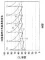
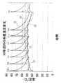
また、電気ポットでの吐出系25内の吐出系内容液71aは通常、図1に示すように湯沸し後や保温中の貯湯内容液71と同じ液量を保っている。しかし、吐出系内容液71aはヒータ11によって加熱されないので貯湯内容液71よりも温度が低い。このため、貯湯内容液71の吐出によってそれが吐出系25に吐出されてくる都度、吐出系25およびそのまわりの温度が上昇する。図5に98度保温の場合の吐出系25各部における温度変化、図6に90度保温の場合の吐出系25各部における温度変化の実験例を示している。図5、図6のいずれも▲1▼は制御基板33の裏面、▲2▼は突出部31の制御基板33を収容したボックス101の内側、▲3▼は吐出口部25cの表面、▲4▼は電源・駆動系基板27の裏面、▲5▼は電動ポンプ26の表面である。98度保温では保温温度が高い分だけ吐出の影響が大きく、▲1▼〜▲5▼のどの個所でも貯湯内容液71の吐出によってはっきりした1つの温度ピークが得られ、90°保温では▲4▼を除いてはっきりした1つの温度ピークが得られ、▲4▼の場合でもその数やタイミングは不定であるが、保温時にはなかった温度ピークが得られている。
【0042】
したがって、吐出系25またはその近傍の温度を吐出系センサ72などによって貯湯内容液71が吐出された実使用の有無を、吐出が電動ポンプ26によって行なわれるか、手動ポンプ10によって行われるか、あるいは器体1を傾けて行われるかといった別なく、吐出に関した1つの電気信号によって実使用Pの信号が確実に得られ、上記のような省エネ時間帯の自動設定が単純なデータによる簡単なデータ処理によって容易に行える。
【0043】
なお、吐出系センサ72はサーミスタなどを用いたもので、吐出系25またはその近傍の温度を検出できる、例えば図1に示すような位置に設けた吐出系センサ72としてあり、実績判定手段73、省エネ保温制御手段74、時計手段77はそれぞれ単独の回路ないしは機器によって、あるいは複数の回路ないしは機器の組合せによって構成することはできる。しかし、本実施例では図2に示すように前記動作制御用のマイクロコンピュータ33aの内部機能として設けてある。
【0044】
また、吐出系温度検知手段としての吐出系センサ72は、図1に示すように吐出系25の近傍にある既設の回路基板としての制御基板33に搭載してある。このように、吐出系センサ72を用いるのに、既設の制御基板33に搭載することによって、特別な取付け部材や配線部材なしに設けられるので、特にコスト上昇の原因にはならない。
【0045】
さらに、前記制御基板33は、前記器体1の肩部6前部へ突出し吐出系25の吐出口部25cを内蔵した突出部31の上面の内側に位置している。これにより制御基板33は、前記器体1の突出部31に内蔵した吐出系25の吐出口部25cの直ぐ上にあって、それに搭載している吐出系センサ72を前記吐出口部25cの近傍に位置させられるので、吐出系25の近傍の温度を検出しやすい。
【0046】
しかも、吐出系センサ72は、図に示すように制御基板33の裏面に設けられるなどして、吐出系25の上方、より具体的には吐出口部25cの上方に位置しているので、吐出系25からの熱を受けやく、吐出系25の温度をより検出しやすい。
【0047】
ここで、制御基板33の上に向いた表面は前記スイッチ類48や図示しない表示ランプなどのハード部品を搭載しているのに対し、制御基板33の裏面はチップ型のマイクロコンピュータ33aなどのチップ部品を面実装してあり、吐出系センサ72をチップ型のサーミスタなどによるものとすることで、部品コストおよび搭載コスト共に低減することができる。
【0048】
図4に示す例では、制御基板33を収容している操作部ボックス101と吐出口部25cとの間に熱伝導部材102を挟みこんである。これによって、吐出系25の吐出口部25cの貯湯内容液71の吐出による温度上昇に対する吐出系センサ72の応答性能を高めることができる。熱伝導部材102は例えば熱伝導用のシリコンシートを利用するのが好適で、少し厚めのものを弾性を利用して挟み込むと特別な成形を必要とすることなく操作部ボックス101と吐出口部25cとの双方に密着させられる。
【0049】
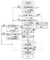
ここで、本実施例のマイクロコンピュータ33aによる制御例について説明すると、図9に主な制御のメインルーチンを示しているように、電源オンによって初期設定が行われた後、各種センサや操作による入出力の処理が行われる。次いで、入出力およびそれに伴う動作制御に関した表示処理が行われる。続いて、初期沸騰や再沸騰を図る沸騰処理、98度や90度での通常保温や、それよりも低く、加熱停止をも含む手動設定および設定での省エネ保温を行う保温処理が行われる。さらに、吐出操作による吐出処理、および前記自動省エネ設定のための省エネ設定処理、その他の処理が行われる。そこで、何らかの異常による異常信号がなく、電源がオフされない限り、それ以降、入出力処理以下の処理が繰り返される。
【0050】
上記省エネ設定処理を行うサブルーチンは図10に示すように、専用キーの操作ないしは省エネキー84など他のキーの長押し操作などの省エネ設定操作があると省エネ設定フラグを0とし、これが次に判定されることによって時計手段77が計時している時刻の取り込みを開始し省エネ設定操作を自動的に行う。ここで、省エネフラグを初期設定によって0にしておくと、人による省エネ設定操作なしに電気ポットの使用初期に自動的に行うことができる。省エネ設定後は省エネ設定フラグが1とされ、これが省エネ設定操作による手動解除や特別な理由による自動解除があるまで、その省エネ設定状態のままリターンする。
【0051】
省エネ設定処理は計時時刻読み込み開始に併せ、吐出に関する実使用Pの電気信号がある都度、貯湯内容液の吐出を伴う実使用Pがある都度、現在時刻を記憶手段に記憶することを繰り返す。この繰り返しに伴い省エネ判定の日時、周、月、季節など所定の日時が経過したかどうかを判定し、経過した時刻でそれまで記憶手段に記憶された実使用Pの実績から、初期設定され、あるいは手動設定などされた食事時の時間ブロックと非食事時の時間ブロックとで異なった基準での実使用の実績経過が判定され、それ以降に適用する省エネ時間帯Zや通常保温時間帯Rを図11に示す省エネ時間帯設定サブルーチンに示すような処理によって設定し、省エネ設定フラグを1にする。
【0052】
図11に示す処理では、まず、現在時間ブロックBが判別され、時間ブロックB1〜Bnのうちの該当する時間ブロックの制御フローに移行する。食事時につき時間ブロックB1で代表して説明すると、開始時刻から終了時刻までの実使用Pの回数がカウントされ、終了時刻までに時間ブロックB1に対応する実使用の回数基準値N1に達したかどうかを判定し、達していない場合は当該時間ブロックB1を省エネ時間帯Zに設定する。達していると通常保温時間帯Rの設定ないしは保温制御にて通常保温時間帯Rの取り扱いとする。このときのカウントは所定の日時が複数日である場合はそれが終了するまで、該当時刻になると繰り返されるので、日単位を越えた累積結果をもって判断できることになる。しかし、具体的な設定操作はどのようにもできる。
【0053】
次に、非食事時につき時間ブロックB4で代表して示すと、開始時刻から終了時刻までに実使用Pがある都度、その時刻の読み込みとともに回数がカウントされ、終了時刻までに時間ブロックB1に対応する実使用の回数が基準値N4に達したかどうかを判定し、達していると省エネ時間帯の設定を行わず、通常保温時間帯を設定するかそのような取り扱いを行う。達していない場合、さらにそれよりも低いサブ基準値N4′以上であるかどうかを判定し、そうであると時間ブロックB4における実使用Pのあった時間帯以外、例えば図8の例の通常保温時間帯R3以外を省エネ時間帯、図8の例の省エネ時間帯Z2、Z3とする。この場合の通常保温時間帯R3は、時間ブロックB4における所定時間内での実使用時間帯よりも前後に適当な時間幅を持った余裕を見て設定するのが実使用の実態から外れないために好適である。このときのカウントも所定の日時が複数日である場合はそれが終了するまで、該当時刻になると繰り返されるので、日単位を越えた累積結果をもって判断できることになる。しかし、具体的な設定操作はどのようにもできる。
【0054】
上記保温処理サブルーチンは図12に示しているように、1つあるいは複数設定された省エネ時間帯Z1・・Znにおける省エネ開始時刻かどうかを、前記計時を基に判定し、そうでなければ、省エネ保温の手動操作があったかどうかを判定し、これもなければ通常保温時間帯Rとして選択された温度での通常保温を行う。省エネ保温の手動操作があると設定された省エネ保温を行うが、省エネ保温中に吐出があると省エネ保温を解除し、通常保温に戻る。設定された省エネ時間帯Z1・・Znにおける省エネ開始時刻になると、省エネ保温に移行してヒータ11をオフし断熱容器としての真空二重容器3によるいわゆる魔法瓶保温を行って省エネ保温を開始し、時間経過とともに保温温度は通常保温の場合よりも低下していく。しかし、魔法瓶保温であることによって急激な温度低下はなく、貯湯内容液71の量や直前での湯温の違いなどによって異なるが8時間程度では60〜70℃程度の温度を保持することができる。
【0055】
省エネ終了時刻になると省エネ保温中に通常保温温度よりも低くなっているので、湯沸しモードなどによる通常保温への立ち上げ処理を行って後通常保温に復帰する。もっとも、この立ち上げ処理は内容液温度を判定した結果行うようにすることができる。
【0056】
省エネ開始時刻から省エネ終了時刻までの間に吐出または再沸騰操作があると、省エネ設定処理でのやり直し制御とは別に、前記同様湯沸しモードなどによる立ち上げ処理をして通常保温への復帰、または沸騰処理による湯沸しをさせ、とりあえず吐出による実使用、または再沸騰による実使用の可能性に対応する。図14にこのような制御例とその場合の内容液の温度変化を示している。通常保温の加熱モードによる設定温度を保っている通常保温時間帯R1から省エネ時間帯Z1が設定された不使用時間帯R1に移行すると、次の通常保温時間帯R2まで加熱が停止されて魔法瓶保温による完全な省エネ保温状態となる。
【0057】
ここで、内容液温度は通常、次の通常保温時間帯R2に移行して通常保温の加熱モードによる立ち上げ時刻まで低下し続ける。このため、図14に示すように省エネ時間帯Z1の途中でユーザを行うと、通常保温での設定温度よりも低い温度の内容液が吐出され、ユーザに不満を与えたり、不満度によっては温度立ち上げのための再沸騰操作を行うといった措置を行わせるなどユーザに不便を与える。そこで、このような省エネ時間帯Z1中に吐出操作や再沸騰操作があった場合、湯沸しモードによる設定保温温度への早期立ち上げ、あるいは湯沸しを行い、かつ、所定の時間tの間通常保温での加熱モードで設定保温温度に保ち、飲料用などで複数回繰り返し使用されるようなことに自動的に対応するようにしている。所定の時間tはそのときの吐出回数や吐出量によって吐出操作が外れないように変更するのが好適である。
【0058】
なお、省エネ保温の場合、手動設定、自動設定にかかわらず、省エネランプ93やまほうびん保温表示110を点灯させておくのがよい。また前記のような立ち上げにおいても、手動設定、自動設定にかかわらず省エネランプ93またはおよび設定保温温度表示111、あるいは現時刻の温度表示112を点滅させておくと特別なモードでの昇温中であることを告知でき好都合である。
【0059】
以上のように省エネ時間帯Z1・・Znの途中に吐出操作があって、立ち上げ処理する場合、液晶表示している現在湯温を数秒間点滅させて告知したり、設定保温温度表示111の点滅と省エネランプ93とを点滅させて告知をしたり、また、それらとともに、あるいは単独でブザーにより100msを3回働かせるといった告知をしたりすることでユーザに制御を特別な立ち上げ処理であることを認知させることができる。
【0060】
また、省エネ時間帯Z1・・Znの途中における吐出操作に代えて、吐出のロック解除操作があったときに立ち上げ処理をしてもよい。吐出ロックは一定時間吐出がないことによって自動設定され、ロック解除は吐出操作に先立って行われるので、吐出に対する温度の立ち上げを早期に開始することができる。
【0061】
また、最初の途中吐出には温度の立ち上げが間にあいにくい場合、最初の吐出があって後に立ち上げ処理して所定時間tの間通常保温するようにもできる。
【0062】
これら、途中吐出や吐出ロックの解除によって立ち上げ処理し、あるいは再沸騰操作によって湯沸しをした後、所定時間tだけ通常保温した後は、再度省エネ保温に戻すのが省エネ上望ましい。省エネ保温に戻すには途中吐出などがある時間の間途絶えることで行うと、途中の使用実態に対応したものとすることができる。
【0063】
また、図12の制御において、省エネ時間帯Z1・・Zn中の吐出操作があったときは、省エネ設定カウンタを+1し、カウントが1回、あるいはそれ以上の所定回数に達したとき、省エネフラグを0にする。これによって、実情に合わなくなった省エネ設定を図10に示す制御にて再度やり直すことになる。この再設定は、設定済の省エネ時間帯の全体について行ってもよいが、そのような省エネ保温中の実使用に関連する特定の省エネ時間帯についてだけ補正するように行い、これが複数、ないしは所定数の省エネ時間帯について行うときは設定済の省エネ時間帯の全体について再設定するようにしてもよい。
【0064】
具体的には、途中吐出が省エネ時間帯Z1・・Znにおけるどのタイミング時刻かによって該当する時間帯を補正することが考えられる。例えば、前記タイミング時刻が該当する省エネ時間帯における通常保温時間帯と隣接する境目近くであるときは、そのタイミング時刻が通常保温時間帯に含まれるように隣接する通常保温時間帯を隣接側に増加し、該当する省エネ時間帯を前記隣接側で短くする。また、省エネ時間帯Z1・・Znにおける吐出タイミングが該当する省エネ時間帯のほぼ中間時刻であると、該当する省エネ時間帯の全体または途中所定時間の間、下限温度を設定した省エネ保温を設定して、設定保温温度への立上がりが早まるようにして以降の使用に対応することもできる。
【0065】
さらに、図12に示す省エネ保温のサブルーチンの具体例を図13に示している。この例では、省エネ保温の開始に際しまず、保温ヒータをオフして省エネ保温、つまり魔法瓶保温状態を開始する。続いて、現在の液量Qと現在の室温TRの取り込みを行う。これは現在の内容液が沸騰するまでに要する時間を判定する要素であって、既述したように内容液の加熱、加熱停止に伴う温度変化であってもよい。次に、図14に示す初期設定され、あるいはユーザが設定した所定時間tにて内容液を沸騰させられる省エネ保温温度T0を判定し、設定する。以降、内容液が設定した省エネ保温温度T0を下回る都度、保温ヒータをオンして省エネ保温温度T0を保つようにする。
【0066】
なお、省エネ保温温度T1は、最低温度を設定しておきどのような場合もこれを下回らないようにし、貯湯内容液71が極端に低温になってしまうのを防止することもできる。
【0067】
以下、本実施例の電気ポットの具体的な構成について、さらに詳述すると、真空二重容器3はステンレス鋼製の内筒4と外筒5により構成され、ヒータ11は既述したように真空二重容器3の一重底部3cに当てがって加熱効率が低下しないようにしている。ヒータ11は容量の違う湯沸しヒータと保温ヒータに分けて併用したり、個別使用したりすることができるが、1つのものを湯沸しモードと保温モードとでデューティー比を変えるなど既に知られた方法で発熱容量を違えて使用するようにもできる。真空二重容器3を収容した外装ケース2は合成樹脂製であって、底部および胴部が一体形成され、胴部の上端に別体の肩部6を嵌め合わせ一体にすることで、真空二重容器3を収容し保持している。真空二重容器3の一重底部には吐出系25が接続され、この吐出系25は真空二重容器3と外装ケース2との間を立ち上がり、器体1の前部に吐出口25dが臨んでいる。吐出系25の途中には遠心ポンプなどである電動ポンプ26が設けられ、吐出系25に流入する内容液を吐出口25dに向け送り出し、吐出するようにしている。しかし、電動ポンプの方式はくみ上げ式、加圧式などを問わず自由に選択することができる。併せ、真空二重容器3の口部に通じる器体1の器体開口12を開閉できるように覆う蓋13に手動ポンプ10が設けられ、押圧板61による押圧操作で真空二重容器3内に加圧空気を吹き込み貯湯内容液71を加圧して吐出系25を通じ押し出し外部に吐出させられるようにしている。手動ポンプ10は電源なしのところで貯湯内容液71を手動吐出して給湯できる利点がある。
【0068】
吐出系25の立上がり部25aは透明管としてそこでの液量が器体1の透明な液量表示窓62から透視できるようにしている。しかし、内容液の液量は立上がり部25aの液量をフォトカプラなどによって段階的に検出して表示し、また各種の制御のための液量データとして用いることもできる。また液量の自動検出は静電容量方式によってもよいし、貯湯内容液71をヒータ11で加熱するときの昇温特性や、ヒータ11の加熱を停止したときの降温特性によっても液量を自動検出することができる。
【0069】
蓋13は真空二重容器3からの蒸気を外部に逃がす蒸気通路17が形成され、蓋13の真空二重容器3内に面する位置の内側開口17aと、外部に露出する外面に形成された外側開口17bとの間で通じている。蒸気通路17の途中には、器体1が横転して貯湯内容液71が進入してきた場合にそれを一時溜め込み、あるいは迂回させて、外側開口17bに至るのを遅らせる安全経路17cを設けてある。これにより、器体1が横転して内容液が蒸気通路17を通じて外部に流出するまでに器体1を起こすなどの処置ができるようになる。また、蒸気通路17には器体1の横転時に、蒸気通路17に進入しようとし、あるいは進入した内容液が先に進むのを阻止するように自重などで働く転倒時止水弁18が適所に設けられている。図示する実施例では内側開口17aの直ぐ内側の一か所に設けてある。
【0070】
蓋13の前部には閉じ位置で肩部6側の係止部19に係合して蓋13を閉じ位置にロックするロック部材21が設けられ、蓋13が閉じられたときに係止部19に自動的に係合するようにばね22の付勢によってロック位置に常時突出するようにしている。これに対応して蓋13にはロック部材21を後退操作して前記ロックを解除するロック解除部材23が設けられている。ロック解除部材23は図1に示すように軸24によって蓋13に枢支されたレバータイプのものとされ、前端23aを親指などで押し下げて反時計回りに回動させることでロック部材21をばね22に抗して後退させてロックを解除し、続いてロック解除操作で起き上がった後端23bを他の指で引き上げることによりロックを解除された蓋13を持ち上げこれを開くことができる。
【0071】
外装ケース2の底と真空二重容器3の底部との間の空間には、前記電動ポンプ26とともに、電源・駆動系基板27を収容する回路ボックス28が設置されている。図示する実施例では回路ボックス28は外装ケース2の底の開口部に一体形成して設けてある。また、回路ボックス28は下向きに開口しこれを閉じる蓋60を設けてある。
【0072】
吐出系25の上部は器体1の突出部31と外装ケース2側のパイプカバー部2dとの間に入った部分で逆U字状のユニットである吐出口部25cを構成し、この吐出口部25cに転倒時止水弁34aおよび前傾時止水弁34bと吐出口25dを設けている。吐出口25dはパイプカバー部2dを通じて下向きに外部に開口している。
【0073】
外装ケース2の底部にある開口には下方から蓋板36を当てがってねじ止めや部分的な係合により取付け、蓋板36の外周部には回転座環37が回転できるように支持して設けられ、器体1がテーブル面などに定置されたときに回転座環37の上で軽く回転して向きを変えられるようにしてある。
【0074】
また、制御基板33に設けた吐出系センサ72は、吐出温度を検出していない間の検出温度を室温としてモニタし、貯湯内容液の湯沸し制御や保温制御、液量判定など各種の制御に用いることができる。
【0075】
なお、上記とは別の省エネ保温方法として、電気ポットにて貯湯内容液71を通常保温や通常保温よりも低い省エネ保温温度T1での省エネ保温をしながら使用状態を継続して吐出操作による実使用に供するのに、設定した省エネ時間帯Zになる都度、加熱を停止し、沸騰操作があると、その時刻の液量Qおよび内容液温度に応じ所定の時間tにて沸騰させられるように変えた加熱容量WHにて湯沸しを行うこともできる。このようにすると、電気ポットの使用継続状態にて設定した省エネ時間帯Zになる都度、加熱を停止して省エネを図りながら、加熱の停止によって貯湯内容液71が通常の保温温度よりも低く自然降温していくのに対しては、沸騰操作がある都度、貯湯内容液71を所定の時間で沸騰させられるよう現在の液量Qと内容液温度とに応じ加熱容量WHを変えて湯沸しを行うので、省エネ保温の時間帯による液量Qの違いや、省エネモード途中での沸騰操作時刻による内容液温度の違いがあっても、所定の所要時間tにて沸騰させることができ、湯沸し時間が不定であったり、湯沸し時間が長すぎたり、省エネ保温温度が一律に高くて省エネ効果を損なったりすることが解消される。
【0076】
もっとも、湯沸しモードは電気ポットの最大加熱容量で極力短時間にて行われるようにするのが普通であるが、以上のように液量Qに対して加熱容量を変えて沸騰までの時間を一定にする場合は、最大加熱容量にて常に湯沸しを行うようにはならない。そこで、一定以上の液量Qの場合に、一律な最大加熱容量としながら先の制御例のように液量Qに対応した省エネ保温温度T1を変更し、一定以下の液量の場合に、省エネ保温温度T1を変更しない加熱を停止した自然降温のままで、最大加熱容量以下の加熱容量の変化で対応するようにもできる。これにより、通常の最大加熱容量を上回るような設定を避けることができる。
【0077】
また、液量Qの判定は、貯湯内容液71が持つ静電容量の大小によって判定してもよいし、フォトセンサなどの水位センサによっても、また、所定水位からの流量や吐出量に基づく減算方式によっても判定することができる。
【0078】
また、過去の実使用Pの実績から省エネ時間帯が繰り返される頻度に対するランク付けを行い、具体的には、省エネ保温時間帯の繰り返しが1日であるのを最低ランク、1ヶ月であるのを最高ランクとし、最高ランクの場合には設定した省エネ時間帯の途中に実使用されることの確率が低いのを利用して、液量Qによる省エネ保温温度T1の変化は行わず、最低温度での省エネ保温制御または加熱停止を行うようにすると、不測な実使に対し不便となることを回避しながら省エネ効率を高めることができる。
【0079】
【発明の効果】
本発明の1つの特徴の省エネ保温方法とそれを適用した電気貯湯容器によれば、電気貯湯容器の使用継続状態にて設定した省エネ時間帯になる都度、通常保温温度よりも低い省エネ保温温度での省エネ保温を行うのに、内容液を所定の時間で沸騰させられるよう現在の液量に応じ省エネ保温温度を変えるので、省エネ保温の時間帯によって液量に違いがあっても、省エネ保温中の沸騰操作にて湯沸しを行う場合、湯沸しモードに設定している加熱容量で所定の所要時間にて沸騰させることができ、湯沸し時間が不定であったり、湯沸し時間が長すぎたり、省エネ保温温度が一律に高くて省エネ効果を損なったりすることが解消される。
【0080】
本発明の他の特徴の省エネ保温方法によれば、電気貯湯容器の使用継続状態にて設定した省エネ時間帯になる都度、加熱を停止して省エネを図りながら、加熱の停止によって内容液が通常保温温度よりも低く自然降温していくのに対しては、内容液を所定の時間で沸騰させられるよう現在の液量に応じ省エネ保温温度を変えて通常保温温度よりも低温での省エネ保温を行うので、省エネ保温の時間帯によって液量に違いがあっても、省エネ保温中の沸騰操作にて湯沸しを行う場合、湯沸しモードに設定している加熱容量で所定の所要時間にて沸騰させることができ、湯沸し時間が不定であったり、湯沸し時間が長すぎたり、省エネ保温温度が一律に高くて省エネ効果を損なったりすることが解消される。
【0081】
液量は、加熱を停止して省エネ保温モードに入ってからの内容液の温度変化によって判定する、さらなる構成によれば、加熱を停止して省エネ保温モードに入ると内容液は自然に降温するが、その降温速度は液量によって違うので、そのときの温度変化、具体的には降温勾配ないしは降温特性や所定温度幅変化する時間などから液量を判定して省エネ保温温度の設定に供することができ、液量検出のためのセンサ類が不要となる。また、自然降温には室温も関係しているので、室温の違いによる沸騰時間のばらつきも特別なモニタなしに併せ解消することができる。
【0082】
液量は、通常保温時の加熱またはおよび加熱停止によって判定する、さらなる構成によれば、通常保温時でも所定の通常保温温度を保つために、加熱をしたり停止したりするので、昇温または降温の速度が液量によって違うし、加熱のオン、オフ繰り返しサイクルに影響するのを利用して、液量を判定し省エネ保温温度の設定に供することができ、液量検出のためのセンサ類が不要となる。また、加熱昇温、自然降温には室温も関係しているので、室温の違いによる沸騰時間のばらつきも、室温の特別なモニタなしに併せ解消することができる。また、省エネ保温モードになる前に次の省エネ時間帯のための省エネ保温温度を設定しておくことができる。
【0083】
省エネ保温中に吐出または沸騰操作があると、その後所定の時間だけ通常保温を行う、さらなる構成によれば、省エネ保温中に吐出や、沸騰操作があると、実使用が繰り返される確率が高いといえるが、その後所定時間の間は通常保温を行うので、省エネ保温モードにて実使用が繰り返されて、その都度省エネ保温温度からの立ち上げが必要になるといったことによるユーザの不便が解消する。
【0084】
液量と省エネ保温温度との関係は、ユーザによる所定の時間の設定に基づき変える、さらなる構成によれば、
液量に応じて設定する省エネ保温温度を、ユーザが限度とする待ち時間に対応して設定する所定の時間によって変更し、省エネ効果を優先するか、待ち時間の短縮を優先するかの選択ができ、便利となる。
【0085】
本発明の別の省エネ保温方法によれば、電気貯湯容器の使用継続状態にて設定した省エネ時間帯になる都度、加熱を停止して省エネを図りながら、加熱の停止によって内容液が通常保温温度よりも低く自然降温していくのに対しては、沸騰操作がある都度、内容液を所定の時間で沸騰させられるよう現在の液量と内容液温度とに応じ加熱容量を変えて湯沸しを行うので、省エネ保温の時間帯による液量の違いや、省エネモード途中での沸騰操作時刻による内容液温度の違いがあっても、所定の所要時間にて沸騰させることができ、湯沸し時間が不定であったり、湯沸し時間が長すぎたり、省エネ保温温度が一律に高くて省エネ効果を損なったりすることが解消される。
【図面の簡単な説明】
【図1】本発明の電気貯湯容器の実施例に係る電気ポットの1つの例を示す断面図である。
【図2】図1の電気ポットの制御回路図である。
【図3】図1の電気ポットの操作部の平面図である。
【図4】図1の電気ポットの別の例を示す一部の断面図である。
【図5】図1の電気ポットの98度保温時の、貯湯内容液の吐出による吐出系各部の温度変化を示すグラフである。
【図6】図1の電気ポットの90度保温時の、貯湯内容液の吐出による吐出系各部の温度変化を示すグラフである。
【図7】液量および液温の違いによる内容液を沸騰させるのに要する時間を示す表である。
【図8】24時間単位での、食事時と非食事時との時間ブロックごとの実使用に関する1日分の実績経過から省エネ時間帯を設定する操作の手順を示す説明図である。
【図9】図2の制御回路の主な制御例を示すメインルーチンのフローチャートである。
【図10】図9における省エネ設定処理サブルーチンのフローチャートである。
【図11】図10における省エネ時間帯設定処理サブルーチンのフローチャートである。
【図12】図9における保温処理サブルーチンのフローチャートである。
【図13】図12の保温処理における省エネ保温処理サブルーチンのフローチャートである。
【図14】省エネ時間帯における途中吐出や再沸騰操作があったときの制御例と、それによる内容液の温度変化を示すタイムチャートである。
【符号の説明】
D 操作部
1 器体
10 手動ポンプ
11 ヒータ
25 吐出系
26 電動ポンプ
32 操作パネル
33 制御基板
33a マイクロコンピュータ
71 貯湯内容液
72 吐出系センサ
73 実績判定手段
74 省エネ保温制御手段
75 記憶手段
76 バックアップ電源
77 時計手段
78 省エネ保温温度設定手段
82 吐出キー
85 再沸騰キー[0001]
TECHNICAL FIELD OF THE INVENTION
The present invention relates to an energy-saving heat retention method and an electric hot water storage container to which the method is applied, and is used for, for example, a household electric pot.
[0002]
[Prior art]
Electric pots are widely used in homes, workplaces, restaurants, etc., but the dependence on them at home is particularly high, with the power being left on except for replacement of the contents, etc. In many cases, the heat retention is continued except during startup and during initial boiling due to replenishment of the content liquid. However, the power consumption of a large refrigerator is comparable to that of a large refrigerator, which is a problem in terms of energy saving.
[0003]
Therefore, it has become possible to save power and save energy by setting the timer for the non-use time zone when going to bed or going out, such as reducing the heat retention temperature, including stopping power supply. In addition, users who are worried about power consumption frequently take measures such as turning off the power supply or setting an energy saving / heating mode. However, this requires frequent operations by the user, which is troublesome.
[0004]
In order to solve this problem, power information when power is supplied to the main unit, which is different from power supply to the control system, is detected and stored in the memory, and the actual use is analyzed from the stored power information. As a result, it is known that the power supply circuit breaker is turned off during a time period when power supply is not necessary (for example, see Patent Document 1). In the device described in
[0005]
In particular, in the energy-saving heat keeping, the heating is temporarily stopped, but after the temperature is lowered to a predetermined lower limit temperature, for example, 60 ° C., the heating is restarted and the energy saving heat keeping is continued so as to maintain the lower limit temperature.
[0006]
[Problems to be solved by the invention]
By the way, energy-saving warming is performed during the period when there is no actual use or the frequency of actual use is low, but there is an intention that there is no inconvenience even in unexpected actual use, rather than turning off the power and turning it off. . However, if the lower limit temperature at the time of energy saving and heat retention is set to one as in the case of
[0007]
Even in actual use with normal heat retention, there is a case where actual use is performed after trying to reboil. Despite the fact that it is considered to be mostly used, it takes a long time to boil because of the low heat retention temperature, and the time required for boiling varies depending on the liquid volume even at the same heat retention temperature. Serving users is confusing to users.
[0008]
For example, if the lower limit temperature is too low, the waiting time until boiling becomes unexpectedly long when the amount of liquid is large, and the user is likely to be dissatisfied or inconvenient. Therefore, if the lower limit temperature is set higher, the energy saving effect is reduced.
[0009]
An object of the present invention is to provide an electric hot water storage container capable of suppressing variation in reboil time due to a liquid amount in an energy saving and heat retaining mode within a predetermined range.
[0010]
[Means for Solving the Problems]
In order to achieve the above object, the energy saving and heat retaining method of the present invention is to continuously use the liquid while keeping the content liquid in the electric hot water storage container at a normal energy saving temperature or an energy saving temperature lower than the normal temperature. In order to provide the actual use by the discharge operation, every time the set energy saving time zone is reached, it is necessary to change the energy saving heat retention temperature according to the current amount of the liquid so that the content liquid can be boiled for a predetermined time. It has two features.
[0011]
In such a configuration, every time the energy saving time period set in the continuous use state of the electric hot water storage container is reached, the content liquid is boiled for a predetermined time to perform the energy saving warming at the energy saving warming temperature lower than the normal warming temperature. The energy saving temperature is changed according to the current amount of liquid so that even if there is a difference in the amount of liquid depending on the energy saving time, if the water is heated by the boiling operation during energy saving, set the water heating mode. It is possible to boil for a predetermined required time with a heating capacity that is present, and it is possible to eliminate indefinite boiling water time, too long boiling water time, and a constant increase in energy-saving heat-retaining temperature to impair the energy-saving effect. .
[0012]
As an electric hot water storage container that achieves such a method, a content liquid is heated by a heater to perform normal operation or energy-saving operation at an energy-saving operation temperature lower than the normal operation temperature while maintaining the use state and realizing the discharge operation. In the electric hot water storage container to be used, a storage means for storing a time zone related to energy saving and heat retention, and according to the current liquid amount so that the content liquid can be boiled for a predetermined time every time the set energy saving time zone is reached. It suffices to have an energy-saving heat-retention temperature setting means for setting the energy-saving heat-retention temperature, and energy-saving heat-retention control means for energy-saving heat retention in the energy-saving time zone corresponding to the set energy-saving heat retention temperature.
[0013]
The energy-saving heat retention method of the present invention also provides the actual use by the discharge operation by continuing the use state while keeping the content liquid in the electric hot water storage container at the normal temperature or at the energy-saving temperature lower than the normal temperature. Nevertheless, every time the set energy saving time zone is reached, once the heating is stopped, the energy saving heat insulation temperature must be changed according to the current liquid volume so that the content liquid can be boiled for a predetermined time. Has other features.
[0014]
In such a configuration, every time the energy saving time period set in the continuous use state of the electric hot water storage container is reached, while heating is stopped to save energy, the heating is stopped and the content liquid naturally lowers below the normal heat retaining temperature. The energy-saving heat retention temperature is changed according to the current liquid volume so that the content liquid can be boiled in a predetermined time, and the energy saving heat retention is performed at a temperature lower than the normal heat retention temperature. Even if there is a difference in the liquid volume, when boiling water by the boiling operation during energy saving warming, it can be boiled for a predetermined required time with the heating capacity set to the boiling water mode, and the boiling time is undefined. It is possible to prevent the water from being heated, the boiling time being too long, and the energy saving heat retaining temperature being uniformly high, thereby impairing the energy saving effect.
[0015]
In a further configuration, the liquid amount is determined based on a change in the temperature of the content liquid after stopping the heating and entering the energy saving heat retaining mode.
When the heating is stopped and the energy saving mode is entered, the temperature of the content liquid drops naturally.However, the rate of temperature drop depends on the amount of liquid, so the temperature change at that time, specifically, the temperature drop gradient or the temperature drop characteristic or the predetermined temperature range change The amount of liquid can be determined from the time to be performed and used for setting the energy-saving heat retaining temperature, and sensors for detecting the amount of liquid are not required. Further, since the room temperature is related to the natural temperature drop, the variation in the boiling time due to the difference in the room temperature can also be eliminated without a special monitor.
[0016]
In a further configuration, the liquid volume is usually determined by heating during heating or by stopping heating.
Heating or stopping is performed to maintain the specified normal heat retention temperature even during normal heat retention, so take advantage of the fact that the rate of temperature increase or decrease depends on the liquid volume and affects the heating on / off cycle. As a result, the liquid amount can be determined and used for setting the energy-saving heat retaining temperature, and sensors for detecting the liquid amount are not required. In addition, since the room temperature is related to the heating temperature rise and the natural temperature decrease, the variation in the boiling time due to the difference in the room temperature can also be eliminated without special monitoring of the room temperature. In addition, before entering the energy saving heat retaining mode, an energy saving heat retaining temperature for the next energy saving time zone can be set.
[0017]
If there is a discharge or boiling operation during the energy-saving warming, the normal warming is performed only for a predetermined time after that.
If there is a discharge or a boiling operation during energy saving heat retention, it can be said that there is a high probability that actual use will be repeated.However, since normal heat retention is performed for a predetermined time thereafter, actual use will be repeated in the energy saving heat retention mode. The inconvenience of the user due to the necessity of starting from the energy-saving warming temperature every time is eliminated.
[0018]
In a further configuration, the relationship between the liquid amount and the energy-saving warming temperature is changed based on the setting of a predetermined time by the user.
The energy-saving warming temperature set according to the liquid volume is changed by a predetermined time set according to the waiting time that the user limits, and the choice of giving priority to the energy-saving effect or shortening the waiting time can be made. Can be convenient.
[0019]
The energy-saving heat retention method of the present invention also provides the actual use by the discharge operation by continuing the use state while keeping the content liquid in the electric hot water storage container at the normal temperature or at the energy-saving temperature lower than the normal temperature. However, every time the set energy saving time period is reached, heating is stopped, and if there is a boiling operation, with a heating capacity changed so that it can be boiled for a predetermined time according to the liquid volume and the content liquid temperature at that time Another feature is to perform a water heater.
[0020]
In such a configuration, every time the energy saving time period set in the continuous use state of the electric hot water storage container is reached, while heating is stopped to save energy, the heating is stopped and the content liquid naturally lowers below the normal heat retaining temperature. Each time there is a boiling operation, the heating capacity is changed according to the current liquid volume and the content liquid temperature so that the content liquid can be boiled for a predetermined time. Even if there is a difference in the liquid volume depending on the band or a difference in the content liquid temperature due to the boiling operation time during the energy saving mode, it is possible to boil for a predetermined required time, and the boiling time is undefined or the boiling time is It is eliminated that the energy saving effect is too long or the energy saving heat retaining temperature is uniformly high and the energy saving effect is lost.
[0021]
Further objects and features of the present invention will become apparent in the following detailed written description. The features of the present invention can be employed alone or in combination as variously as possible.
[0022]
【Example】
Hereinafter, embodiments of the present invention will be described in detail with reference to the drawings to provide an understanding of the present invention. The following description is a specific example of the present invention and does not limit the scope of the claims.
[0023]
The present embodiment is an example of a household electric pot, and uses an insulated container as an inner container. The insulated container of the example shown in FIG. 1 has a
[0024]
As shown in FIG. 3, the
[0025]
The electric pot serving as the electric hot water storage container of the present embodiment is, particularly, an energy-saving heat retaining method, in which the hot
[0026]
In the continuous use state in which the power of the electric pot is turned on in this way, the set energy saving time zone Z1 ~ Z4 Each time it becomes0 Energy saving heat retention temperature T lower than1 In order to perform the energy-saving heat-retention at the temperature, the energy-saving heat-retention temperature T according to the current liquid amount so that the hot-
[0027]
Note that the normal heat retention is the heating capacity WH shown in FIG. 14 that matches the set selected heat retention temperature.1 , But lower energy saving temperature T1 Heating capacity WH for energy conservation and heat retention in Japan2 Is the heating capacity WH during normal heat retention as shown in FIG.1 Lower than. Here, WH0 > WH1 > WH2 And the heating capacity WH1 Are set depending on the selected heat retention temperature, and the heating capacity WH2 Are also set to a plurality according to the liquid amount Q detected at each time. However, the heating capacity WH can be variously set by the duty ratio, the power consumption, and the like.
[0028]
In order to achieve the above-described method, the hot
[0029]
In addition, energy saving time zone Z1 ~ Z4 Can be set manually by a user or the like, but the actual use results of the user in accordance with a change in time or a change in elapsed time in a predetermined period are stored in the
[0030]
Energy saving warming temperature T1 Is the normal warming temperature T0 In this case, the heating may be stopped in any case to shift from the normal warming mode to the energy saving warming mode, thereby starting the energy saving and the energy saving warming temperature T due to the temperature change of the content liquid at that time.1 The automatic setting operation can be reliably started. Therefore, apart from the above-described energy-saving heat retention method, the actual use of the hot
[0031]
As a result, the energy saving time zone Z set in the continuous use state of the electric hot water storage container is set.1 ~ Zn, the heating is stopped to save energy while the heating is stopped so that the stored hot
[0032]
In addition, the liquid amount Q can be determined based on a change in the temperature of the content liquid after the heating is stopped and the apparatus enters the energy saving and heat retaining mode. In this way, when the heating is stopped and the operation enters the energy-saving warming mode, the hot
[0033]
Further, the liquid amount Q can also be determined by heating during normal warming or by stopping heating. In this way, even at the time of normal warming, the predetermined normal warming temperature T0 In order to maintain the temperature, heating is performed or stopped, so the rate of temperature rise or fall differs depending on the amount of liquid, and the heating ON / OFF repetition cycle is different. , Energy saving heat retention temperature T1 Can be provided. Therefore, sensors for detecting the liquid amount are not required. In addition, since the room temperature is related to the heating temperature rise and the natural temperature decrease, the variation in the boiling time due to the difference in the room temperature can also be eliminated without special monitoring of the room temperature. Also, before the energy saving mode is set, the next energy saving time zone Z1 Energy saving heat-retention temperature for Zn can be set.
[0034]
Also, during the energy-saving warm mode, the energy-saving time zone Z1 If there is a discharge or boiling operation as shown in FIG. 14 in the middle of Zn, the normal temperature is kept for a predetermined time t1 thereafter. Thus, if there is a discharge or a boiling operation during the energy saving and heat retaining mode, it can be said that the probability of actual use being repeated is high. However, after that, the normal heat retention is performed for a predetermined time t1, so that the actual use is repeated in the energy saving heat retention mode, and the energy saving temperature T every time is used.1 The inconvenience of the user due to the necessity of startup from the server is eliminated.
[0035]
Here, the difference in the waiting time required for boiling depending on the liquid amount and the liquid temperature is as shown in FIG. 7 in the electric pot having a capacity of 3 L according to the experimental example of the present inventor, and varies in various ways. Assuming that the user's waiting time is limited to, for example, 7 minutes, the energy saving heat-retention temperature T is obtained at the liquid amount Q1 of 7/71 Is 80 ° C, energy saving heat retention temperature T at 6/7 liquid volume Q21 Energy saving temperature T at 75 ° C and 5/7 liquid volume Q31 Is between 70-75 ° C and energy saving heat retention temperature T at 4/7 liquid volume Q4.1 Is energy saving heat retention temperature T at 65 ° C and 3/7 liquid volume Q5.1 Is 55 ° C, energy saving warming temperature T at 2/7 liquid volume Q61 May be set at 35 to 30 ° C., and at 1/7 of the liquid volume Q2, the energy-saving warming temperature T1 The waiting time can be reduced to 5 minutes even when the temperature is set to 20 ° C., and the waiting time for the user in the liquid volumes Q1 to Q3 can be reduced as compared with the case where the heat retaining temperature is uniformly set to 60 ° C. There is no great difference between the liquid amounts Q4 and Q5, and the waiting time is short at the liquid amounts Q6 and Q7, and a high energy saving effect can be obtained. However, the waiting time seems to be around 5 minutes as standard.
[0036]
However, the liquid amount Q and the energy-saving warming temperature T1 Can be changed based on the setting of the predetermined time t1 by the user. As a result, the energy saving temperature T set according to the liquid amount Q1 Is changed according to a predetermined time t1 set in accordance with the waiting time set by the user, and it is convenient to select between giving priority to the energy saving effect and giving priority to shortening the waiting time.
[0037]
Here, the energy saving time zone Z shown in FIG.1 ~ Z4 Is set in the time block B at the time of meal shown in FIG.1 , B3 , B5 And the other time block B2 , B4 , B6 Thus, the setting is made based on the different handling as the actual use result by the actual use P, that is, the weight of the actual use P at the time of meal is increased, and the weight of the actual use P at the time of non-meal is reduced. In general, a meal time zone that is easily used in actual meals is set to a normal warming time zone R.1 ~ R4 Priority to make it easier to match the actual situation.
[0038]
More specifically, a time block B at the time of meal in units of one day during the time measured by the clock means 771 , B3 , B5 Time interval t corresponding to1 ~ T2 , T3 ~ T4 , T5 ~ T6 And time block B when not eating2 , B4 , B6 Time interval t corresponding to2 ~ T3 , T4 ~ T5 , T6 ~ T1 The actual use P performance is determined by the performance determination means 73 for each time, and the energy-saving heat retention control1 , B3 , B5 If the actual use P is at least once, the normal warming time zone R1 ~ R3 , While non-meal time block B2 , B4 , B6 Then, when the actual use P is less than twice, the normal heat retention time zone R is not set, but the energy saving time zone Z is set. However, time block B when not eating2 , B4 , B6 Because it often lasts a long time, including at bedtime, it often does not meet the actual situation when viewed only by the number of actual uses P during that time. Therefore, in the example of FIG.2 , B4 , B6 Then, a predetermined time t2 If there is more than one actual use during this period, it is considered that the frequency of actual use is high,3 Is set.
[0039]
As the determination of such a result is made based on the result of accumulating 24 hours of actual use data for several days, it is necessary to more accurately determine whether or not the regular actual use does not require setting the normal heat retention time R. Can be. In addition to the several-day cycle, one-week cycle, several-week cycle, one-month cycle, several-month cycle, actual progress of user's actual use from long-term stored data through the four-season cycle, or usage pattern, life pattern Can be easily and accurately determined and responded to. In order to cope with the pattern cycle for each day of the week or more, it is preferable to employ a calendar function as the clock means 77.
[0040]
By the way, according to the above-described
[0041]
Also, as shown in FIG. 1, the discharge system contents liquid 71a in the
[0042]
Therefore, the temperature of the
[0043]
Note that the
[0044]
Further, the
[0045]
Further, the
[0046]
Moreover, since the
[0047]
Here, the upper surface of the
[0048]
In the example shown in FIG. 4, the
[0049]
Here, an example of control by the
[0050]
As shown in FIG. 10, in the subroutine for performing the energy saving setting process, when there is an energy saving setting operation such as an operation of a dedicated key or a long press operation of another key such as the energy saving key 84, the energy saving setting flag is set to 0, and this is determined next. Then, the
[0051]
The energy saving setting process repeats storing the current time in the storage unit whenever there is an electric signal of the actual use P relating to the discharge and whenever there is the actual use P accompanied by the discharge of the hot-water content liquid, simultaneously with the start of reading of the timekeeping time. With this repetition, it is determined whether or not a predetermined date and time, such as the date and time of energy saving determination, week, month, and season, has elapsed. Alternatively, the elapsed time of actual use is determined based on different standards in the time block at the time of meal and the time block at the time of non-meal, which are set manually, and the energy saving time zone Z and the normal warming time zone R applied thereafter are determined. This is set by the processing shown in the energy saving time zone setting subroutine shown in FIG. 11, and the energy saving setting flag is set to 1.
[0052]
In the processing shown in FIG. 11, first, the current time block B is determined,1 To the control flow of the corresponding time block of Bn. Time block B per meal1 The number of times of actual use P from the start time to the end time is counted, and the time block B1 Reference number N of actual use corresponding to1 It is determined whether or not the time block B has been reached.1 Is set to the energy saving time zone Z. If it has reached, the normal heat retention time zone R is set or the normal heat retention time zone R is handled by the heat retention control. If the predetermined date and time is a plurality of days, the count is repeated at the corresponding time until the end of the count, so that the judgment can be made based on the cumulative result exceeding the day unit. However, the specific setting operation can be performed in any manner.
[0053]
Next, time block B for non-meal time4 Each time there is an actual use P from the start time to the end time, the number of times is read and the number is counted, and the time block B is read by the end time.1 Is the reference value N4 It is determined whether or not the time has been reached. If the time has been reached, the energy saving time zone is not set, and the normal heat insulation time zone is set or such handling is performed. If not, then a lower sub-reference value N4 'Is greater than or equal to, and if so, the time block B4 Other than the time zone where the actual use P was performed, for example, the normal warming time zone R in the example of FIG.3 Other than energy saving time zone, energy saving time zone Z in the example of FIG.2 , Z3 And Normal heat retention time zone R in this case3 Is the time block B4 It is preferable to set with a margin having an appropriate time width before and after the actual use time zone within the predetermined time in, because it does not deviate from the actual use situation. If the predetermined date and time is a plurality of days, the count at this time is repeated at the corresponding time until the end of the predetermined date and time. Therefore, the count can be determined based on the cumulative result exceeding the day unit. However, the specific setting operation can be performed in any manner.
[0054]
As shown in FIG. 12, one or more energy saving time zones Z1 It is determined whether or not it is the energy saving start time in Zn based on the time measurement, otherwise, it is determined whether or not a manual operation of energy saving heat retention has been performed, and otherwise, the temperature selected as the normal heat retention time zone R Perform normal warming in When the energy-saving warming is manually operated, the set energy-saving warming is performed, but if there is a discharge during the energy-saving warming, the energy-saving warming is canceled, and the normal warming is returned. Set energy saving time zone Z1 When the energy-saving start time in Zn is reached, the operation shifts to energy-saving heat retention, the
[0055]
When the energy saving end time is reached, the temperature is lower than the normal warming temperature during the energy saving warming. Therefore, a startup process to the normal warming by a water heater mode or the like is performed, and then the normal warming is restored. However, this start-up process can be performed as a result of determining the content liquid temperature.
[0056]
If there is a discharge or re-boiling operation between the energy-saving start time and the energy-saving end time, apart from the redo control in the energy-saving setting process, a start-up process such as the water heater mode as described above is performed, and a return to normal heat retention, or The water is heated by boiling, and the possibility of actual use by discharge or re-boiling is met. FIG. 14 shows such a control example and the temperature change of the content liquid in that case. Normal heat retention time zone R in which the set temperature in the normal heat retention heating mode is maintained1 Energy saving time zone Z1 Unused time zone R with1 To the next normal warming time zone R2 Heating is stopped until the thermos is completely insulated.
[0057]
Here, the temperature of the content liquid is usually set in the next normal heat retention time zone R.2 And continues to decrease until the startup time in the heating mode for normal heat retention. For this reason, as shown in FIG.1 If the user performs the process in the middle of the process, the content liquid at a temperature lower than the set temperature in the normal heat retention is discharged, giving a user dissatisfaction, and depending on the degree of dissatisfaction, taking measures such as performing a re-boiling operation for starting up the temperature. Cause inconvenience to the user. Therefore, such energy saving time zone Z1 If there is a discharge operation or a re-boiling operation during the operation, the temperature is raised to the set warming temperature in the water heating mode at an early stage, or the water is heated, and the heating temperature is set to the set warming temperature in the normal warming mode for a predetermined time t. It is designed to automatically cope with repeated use for beverages and the like a plurality of times. The predetermined time t is preferably changed according to the number of ejections and the ejection amount at that time so that the ejection operation is not deviated.
[0058]
In addition, in the case of energy saving heat retention, it is preferable to light the
[0059]
As mentioned above, energy saving time zone Z1 If there is a discharge operation in the middle of Zn and the start-up process is performed, the current hot water temperature displayed on the liquid crystal will be blinked for a few seconds to notify, or the set temperature display 111 and the
[0060]
In addition, energy saving time zone Z1 ···························································································································································· The discharge lock is automatically set when there is no discharge for a certain period of time, and the lock release is performed prior to the discharge operation, so that the temperature rise for discharge can be started early.
[0061]
Further, when it is difficult to raise the temperature during the first halfway discharge, it is also possible to perform the start-up processing after the first discharge and keep the normal temperature for a predetermined time t.
[0062]
It is desirable from the standpoint of energy saving to return to the energy-saving heat retention after normal startup for a predetermined time t after the start-up process is performed by releasing these discharges or the release lock, or after the water is boiled by the re-boiling operation. When returning to the energy-saving heat retention by stopping the discharge for a certain period of time or the like for a certain period of time, it is possible to correspond to the actual use during the process.
[0063]
In the control shown in FIG.1 ··············································· Sets the energy saving setting counter to +1 when there is a discharge operation in Zn, and sets the energy saving flag to 0 when the count reaches one or more predetermined times. As a result, the energy saving setting that no longer matches the actual situation is redone by the control shown in FIG. This resetting may be performed for the entire set energy saving time zone.However, the resetting is performed only for the specific energy saving time zone related to the actual use during such energy saving and warming. When the operation is performed for a number of energy saving time zones, the entire energy saving time zone that has already been set may be reset.
[0064]
Specifically, the discharge in the middle is in the energy saving time zone Z.1 It is conceivable to correct the corresponding time zone depending on which timing time in Zn. For example, when the timing time is near a boundary adjacent to the normal warming time zone in the corresponding energy saving time zone, the adjacent normal warming time zone is increased to the adjacent side so that the timing time is included in the normal warming time zone. Then, the corresponding energy saving time zone is shortened on the adjacent side. In addition, energy saving time zone Z1 ..If the discharge timing in Zn is almost the middle of the energy saving time zone, the energy saving heat insulation temperature with the lower limit temperature set is set for the entire energy saving time zone or for a predetermined time in the middle, and the temperature is set to the set heat insulation temperature. It is also possible to cope with the subsequent use by making the rise of the battery quicker.
[0065]
FIG. 13 shows a specific example of the subroutine for energy saving and heat retention shown in FIG. In this example, when the energy-saving heat retention is started, first, the heat retention heater is turned off to start the energy-saving heat retention, that is, the thermos thermal insulation state. Subsequently, the current liquid amount Q and the current room temperature TR Import This is an element for determining the time required for the current content liquid to boil, and may be a temperature change accompanying heating or stopping the heating of the content liquid as described above. Next, the energy-saving heat-retaining temperature T at which the content liquid is boiled at a predetermined time t which is initially set or set by the user shown in FIG.0 Is determined and set. After that, the energy saving temperature T set by the content liquid0 Every time the temperature falls below, the heat insulation heater is turned on and the energy saving heat insulation temperature T0 To keep
[0066]
In addition, the energy-saving heat retention temperature T1 In this case, the minimum temperature is set so that it does not fall below this value in any case, and it is possible to prevent the temperature of the hot
[0067]
Hereinafter, the specific configuration of the electric pot of the present embodiment will be described in more detail. The vacuum
[0068]
The rising
[0069]
The
[0070]
A locking
[0071]
In the space between the bottom of the
[0072]
The upper part of the
[0073]
A
[0074]
Further, the
[0075]
In addition, as another energy-saving heat-retaining method, energy-saving heat-retaining temperature T lower than the normal heat or the normal temperature of the hot-
[0076]
However, it is normal that the water heating mode is performed with the maximum heating capacity of the electric pot as short as possible, but as described above, the heating capacity is changed with respect to the liquid amount Q to keep the time until boiling constant. In such a case, it is not always possible to perform water heating at the maximum heating capacity. Therefore, when the liquid amount Q is equal to or more than a certain value, the energy-saving warming temperature T corresponding to the liquid amount Q as in the previous control example while maintaining the uniform maximum heating capacity.1 Is changed, and when the liquid volume is below a certain level, the energy saving heat retaining temperature T1 It is also possible to cope with a change in the heating capacity that is equal to or less than the maximum heating capacity while the heating is stopped and the natural cooling is stopped. As a result, a setting that exceeds the normal maximum heating capacity can be avoided.
[0077]
Further, the determination of the liquid amount Q may be made based on the magnitude of the capacitance of the hot
[0078]
In addition, the frequency of repetition of the energy-saving time zone is ranked based on the results of actual use P in the past, and specifically, the repetition of the energy-saving and heat-retention time zone is one day, and the minimum rank is one month. The highest rank is used. In the case of the highest rank, using the fact that the probability of actual use during the set energy saving time zone is low, the energy saving warming temperature T1 is not changed by the liquid amount Q. When the energy saving heat retention control or the heating stop is performed, the energy saving efficiency can be enhanced while avoiding inconvenience to unexpected actual use.
[0079]
【The invention's effect】
According to the energy-saving heat retention method of one aspect of the present invention and the electric water storage container to which the method is applied, every time the energy-saving time period set in the continuous use state of the electric water storage container is reached, the energy-saving heat retention temperature lower than the normal heat retention temperature is used. The energy-saving warming temperature is changed according to the current amount of liquid so that the content liquid can be boiled in a predetermined time when performing energy-saving warming. When the water is heated by the boiling operation, the water can be boiled for a predetermined required time with the heating capacity set in the water heating mode. Can be prevented from being uniformly high and impairing the energy saving effect.
[0080]
According to the energy-saving heat retention method according to another feature of the present invention, the content liquid is usually reduced by stopping the heating while stopping the heating every time the energy saving time period set in the continuous use state of the electric hot water storage container is used to save energy. In contrast to the natural temperature lowering than the warming temperature, the energy saving warming temperature is changed at a lower temperature than the normal warming temperature by changing the energy saving warming temperature according to the current liquid volume so that the content liquid can be boiled in a predetermined time. Therefore, even if there is a difference in the amount of liquid depending on the time of energy conservation and heat retention, if water is to be boiled by the boiling operation during energy conservation and heat retention, it should be boiled for a predetermined time with the heating capacity set in the water heating mode. It is possible to solve the problem that the water heating time is not fixed, the water heating time is too long, and the energy saving / heating temperature is uniformly high and the energy saving effect is lost.
[0081]
The liquid volume is determined by the temperature change of the content liquid after stopping the heating and entering the energy saving heat retaining mode. According to a further configuration, when the heating is stopped and the energy saving heat retaining mode is entered, the content liquid naturally cools down. However, the rate of temperature decrease depends on the amount of liquid, so determine the amount of liquid from the temperature change at that time, specifically, the temperature drop gradient or the temperature drop characteristic or the time for changing the predetermined temperature range, and use it to set the energy-saving warming temperature. This eliminates the need for sensors for detecting the liquid amount. Further, since the room temperature is related to the natural temperature drop, the variation in the boiling time due to the difference in the room temperature can also be eliminated without a special monitor.
[0082]
The liquid amount is determined by heating or stopping the heating during the normal warming.According to a further configuration, the heating or stopping is performed to maintain the predetermined normal warming temperature even during the normal warming, so that the temperature is raised or Utilizing the fact that the rate of temperature drop depends on the liquid amount and affects the cycle of heating on and off, it is possible to determine the liquid amount and use it to set the energy saving and warming temperature, and sensors for detecting the liquid amount Becomes unnecessary. In addition, since the room temperature is related to the heating temperature rise and the natural temperature decrease, the variation in the boiling time due to the difference in the room temperature can also be eliminated without special monitoring of the room temperature. In addition, before entering the energy saving heat retaining mode, an energy saving heat retaining temperature for the next energy saving time zone can be set.
[0083]
If there is a discharge or boiling operation during energy-saving heat retention, the normal temperature is kept for a predetermined time thereafter. According to a further configuration, if there is a discharge or boiling operation during energy-saving heat retention, there is a high probability that actual use will be repeated. However, since the normal warming is performed for a predetermined time thereafter, actual use is repeated in the energy saving warming mode, and the inconvenience of the user due to the need to start up from the energy saving warming temperature each time is solved.
[0084]
According to a further configuration, the relationship between the liquid amount and the energy-saving warming temperature is changed based on a predetermined time set by the user.
The energy-saving warming temperature set according to the liquid volume is changed by a predetermined time set according to the waiting time that the user limits, and the choice of giving priority to the energy-saving effect or shortening the waiting time can be made. Can be convenient.
[0085]
According to another energy-saving heat retention method of the present invention, every time the energy-saving time period set in the continuous use state of the electric hot water storage container is reached, heating is stopped to save energy, and the content liquid is heated to a normal temperature by stopping the heating. When the temperature drops naturally, the boiling water is changed by changing the heating capacity according to the current liquid amount and the content liquid temperature so that the content liquid can be boiled for a predetermined time every time there is a boiling operation. Therefore, even if there is a difference in the amount of liquid depending on the time of energy saving and heat retention, or a difference in the content liquid temperature depending on the boiling operation time during the energy saving mode, it is possible to boil for a predetermined required time, and the boiling time is undefined. It is possible to eliminate the problem that the energy saving time is too long, or the energy saving heat retaining temperature is uniformly high and the energy saving effect is lost.
[Brief description of the drawings]
FIG. 1 is a sectional view showing one example of an electric pot according to an embodiment of the electric hot water storage container of the present invention.
FIG. 2 is a control circuit diagram of the electric pot of FIG.
FIG. 3 is a plan view of an operation unit of the electric pot of FIG. 1;
FIG. 4 is a partial cross-sectional view showing another example of the electric pot of FIG. 1;
FIG. 5 is a graph showing a change in temperature of each part of the discharge system due to discharge of the hot water content liquid when the electric pot of FIG. 1 is kept at a temperature of 98 degrees.
FIG. 6 is a graph showing a temperature change of each part of a discharge system due to discharge of a hot water content liquid when the electric pot of FIG. 1 is kept at a temperature of 90 degrees.
FIG. 7 is a table showing the time required for boiling the content liquid depending on the difference in the liquid amount and the liquid temperature.
FIG. 8 is an explanatory diagram showing a procedure of an operation for setting an energy saving time zone based on a lapse of one day of actual use in actual use for each time block between a meal and a non-meal in a 24-hour unit.
FIG. 9 is a flowchart of a main routine showing a main control example of the control circuit of FIG. 2;
FIG. 10 is a flowchart of an energy saving setting processing subroutine in FIG. 9;
11 is a flowchart of an energy saving time zone setting processing subroutine in FIG.
FIG. 12 is a flowchart of a heat retention processing subroutine in FIG. 9;
FIG. 13 is a flowchart of an energy-saving heat retention processing subroutine in the heat retention processing of FIG. 12;
FIG. 14 is a time chart showing a control example when there is a halfway discharge or re-boiling operation in the energy saving time zone, and a temperature change of the content liquid due to the control.
[Explanation of symbols]
D Operation unit
1 body
10 Manual pump
11 heater
25 Discharge system
26 Electric pump
32 Operation panel
33 control board
33a microcomputer
71 Hot water storage liquid
72 Discharge system sensor
73 Achievement judgment means
74 Energy saving and heat control means
75 Storage means
76 Backup power supply
77 Clock Means
78 Energy saving temperature setting means
82 Discharge key
85 Reboil Key
Claims (8)
Translated fromJapanese省エネ保温に関する時間帯を記憶した記憶手段と、設定した省エネ時間帯になる都度、内容液を所定の時間で沸騰させられるように現在の液量に応じ省エネ保温温度を設定する省エネ保温温度設定手段と、設定された省エネ保温温度にて対応する省エネ時間帯での省エネ保温を行う省エネ保温制御手段とを備えたことを特徴とする電気貯湯容器。In an electric hot water storage container, the use liquid is heated by a heater to maintain a normal state of use or an energy-saving heat-retention temperature lower than the normal heat-retention temperature while continuing to be used for actual use by a discharge operation.
Storage means for storing a time zone related to energy saving and heat retention, and energy saving heat retention temperature setting means for setting an energy saving heat retention temperature according to the current liquid amount so that the content liquid can be boiled for a predetermined time every time the set energy saving time zone is reached. An electric hot water storage container comprising: an energy-saving thermal insulation control unit that performs energy-saving thermal insulation in an energy-saving time zone corresponding to a set energy-saving thermal insulation temperature.
Priority Applications (1)
| Application Number | Priority Date | Filing Date | Title |
|---|---|---|---|
| JP2003148161AJP3903958B2 (en) | 2003-05-26 | 2003-05-26 | Energy-saving warming method |
Applications Claiming Priority (1)
| Application Number | Priority Date | Filing Date | Title |
|---|---|---|---|
| JP2003148161AJP3903958B2 (en) | 2003-05-26 | 2003-05-26 | Energy-saving warming method |
Publications (2)
| Publication Number | Publication Date |
|---|---|
| JP2004344588Atrue JP2004344588A (en) | 2004-12-09 |
| JP3903958B2 JP3903958B2 (en) | 2007-04-11 |
Family
ID=33534480
Family Applications (1)
| Application Number | Title | Priority Date | Filing Date |
|---|---|---|---|
| JP2003148161AExpired - Fee RelatedJP3903958B2 (en) | 2003-05-26 | 2003-05-26 | Energy-saving warming method |
Country Status (1)
| Country | Link |
|---|---|
| JP (1) | JP3903958B2 (en) |
Cited By (1)
| Publication number | Priority date | Publication date | Assignee | Title |
|---|---|---|---|---|
| JP2006341269A (en)* | 2005-06-08 | 2006-12-21 | Taiyo Denki Sangyo Kk | Solder melting device |
Families Citing this family (1)
| Publication number | Priority date | Publication date | Assignee | Title |
|---|---|---|---|---|
| WO2012007260A1 (en)* | 2010-07-16 | 2012-01-19 | Nestec S.A. | Advanced heating device |
- 2003
- 2003-05-26JPJP2003148161Apatent/JP3903958B2/ennot_activeExpired - Fee Related
Cited By (1)
| Publication number | Priority date | Publication date | Assignee | Title |
|---|---|---|---|---|
| JP2006341269A (en)* | 2005-06-08 | 2006-12-21 | Taiyo Denki Sangyo Kk | Solder melting device |
Also Published As
| Publication number | Publication date |
|---|---|
| JP3903958B2 (en) | 2007-04-11 |
Similar Documents
| Publication | Publication Date | Title |
|---|---|---|
| JP3903958B2 (en) | Energy-saving warming method | |
| JP3903950B2 (en) | Energy-saving warming method | |
| JP3864926B2 (en) | Energy-saving warming method and electric hot water storage container using it | |
| JP3801150B2 (en) | Energy-saving warming method | |
| JP4052328B2 (en) | Energy-saving warming method and electric hot water storage container using it | |
| JP3801149B2 (en) | Energy-saving warming method and electric hot water storage container using it | |
| JP3912392B2 (en) | Energy-saving warming method and electric hot water storage container using it | |
| JP3156656B2 (en) | Electric hot water storage container | |
| JP4096970B2 (en) | Energy-saving warming method | |
| JP3788451B2 (en) | Energy-saving warming method and electric hot water storage container to which this is applied | |
| JP2004313343A (en) | Energy-saving heat retention method and electric hot water storage container using it | |
| JP4026658B2 (en) | Energy-saving warming method | |
| JP3690306B2 (en) | Electric hot water storage container | |
| JP2004065997A (en) | Electric hot water storage container | |
| JP3876859B2 (en) | Electric hot water storage container | |
| JP3538153B2 (en) | an electronic pot | |
| JP4434087B2 (en) | Electric hot water storage container | |
| JP3613252B2 (en) | an electronic pot | |
| JPH0718335Y2 (en) | Electric hot water storage container | |
| JP2003125931A (en) | an electronic pot | |
| JP2936212B2 (en) | Rice cooker | |
| JP2002272614A (en) | Electric hot water storage container | |
| JP2005296054A (en) | Electric kettle with tea function | |
| JPH0298325A (en) | Electric hot water storage receptacle | |
| JP2004337465A (en) | Steamer |
Legal Events
| Date | Code | Title | Description |
|---|---|---|---|
| A621 | Written request for application examination | Free format text:JAPANESE INTERMEDIATE CODE: A621 Effective date:20050506 | |
| A977 | Report on retrieval | Free format text:JAPANESE INTERMEDIATE CODE: A971007 Effective date:20060803 | |
| A131 | Notification of reasons for refusal | Effective date:20060926 Free format text:JAPANESE INTERMEDIATE CODE: A131 | |
| A521 | Written amendment | Free format text:JAPANESE INTERMEDIATE CODE: A523 Effective date:20061116 | |
| TRDD | Decision of grant or rejection written | ||
| A01 | Written decision to grant a patent or to grant a registration (utility model) | Effective date:20061219 Free format text:JAPANESE INTERMEDIATE CODE: A01 | |
| A61 | First payment of annual fees (during grant procedure) | Free format text:JAPANESE INTERMEDIATE CODE: A61 Effective date:20070101 | |
| R150 | Certificate of patent (=grant) or registration of utility model | Free format text:JAPANESE INTERMEDIATE CODE: R150 | |
| FPAY | Renewal fee payment (prs date is renewal date of database) | Year of fee payment:4 Free format text:PAYMENT UNTIL: 20110119 | |
| S531 | Written request for registration of change of domicile | Free format text:JAPANESE INTERMEDIATE CODE: R313531 | |
| FPAY | Renewal fee payment (prs date is renewal date of database) | Free format text:PAYMENT UNTIL: 20110119 Year of fee payment:4 | |
| R371 | Transfer withdrawn | Free format text:JAPANESE INTERMEDIATE CODE: R371 | |
| FPAY | Renewal fee payment (prs date is renewal date of database) | Free format text:PAYMENT UNTIL: 20110119 Year of fee payment:4 | |
| FPAY | Renewal fee payment (prs date is renewal date of database) | Free format text:PAYMENT UNTIL: 20120119 Year of fee payment:5 | |
| FPAY | Renewal fee payment (prs date is renewal date of database) | Free format text:PAYMENT UNTIL: 20120119 Year of fee payment:5 | |
| FPAY | Renewal fee payment (prs date is renewal date of database) | Free format text:PAYMENT UNTIL: 20130119 Year of fee payment:6 | |
| LAPS | Cancellation because of no payment of annual fees |