JP2004344427A - Magnetic anchor guidance system for endoscope and treatment method by endoscope using magnetic anchor guidance system - Google Patents
Magnetic anchor guidance system for endoscope and treatment method by endoscope using magnetic anchor guidance systemDownload PDFInfo
- Publication number
- JP2004344427A JP2004344427AJP2003145333AJP2003145333AJP2004344427AJP 2004344427 AJP2004344427 AJP 2004344427AJP 2003145333 AJP2003145333 AJP 2003145333AJP 2003145333 AJP2003145333 AJP 2003145333AJP 2004344427 AJP2004344427 AJP 2004344427A
- Authority
- JP
- Japan
- Prior art keywords
- magnetic
- magnetic anchor
- endoscope
- anchor
- guidance system
- Prior art date
- Legal status (The legal status is an assumption and is not a legal conclusion. Google has not performed a legal analysis and makes no representation as to the accuracy of the status listed.)
- Granted
Links
Images


Landscapes
- Surgical Instruments (AREA)
- Endoscopes (AREA)
Abstract
Translated fromJapaneseDescription
Translated fromJapanese【0001】
【技術分野】
本発明は、内視鏡観察下で病変部を切除する際に用いる、内視鏡用磁気アンカー誘導システム及び磁気アンカー誘導システムを用いた内視鏡による処置方法に関する。
【0002】
【従来技術及びその問題点】
従来、通常の手術において人体内部の病変部を切除する場合においては、把持鉗子を用いて病変部を持ち上げることにより、病変部と隣接する正常組織との間隔を広げ、その状態で病変部と正常組織との間を切除している。しかし、例えば内視鏡的粘膜切除術(EMR)では、体内には内視鏡を一台しか挿入できないため、病変部を持ち上げることができず、注射針で病変部の周囲の正常粘膜に生理食塩水を注入して病変部を浮き上がらせ、その状態で高周波ナイフやスネアなどを用いて病変部と正常粘膜の間の切除を行っていた。
【0003】
しかし、このような従来の方法では、病変部を十分な位置まで持ち上げることができなかったため、病変部と正常組織との境界の切除部分を十分確保することができなかった。
また、病変部が扁平な形状である場合は、切除部分を作りだすことができないこともあった。
【0004】
さらに、切除作業中において、すでに切除した病変部が正常組織上に落ち込むことにより内視鏡による視界を妨げることがあり、特に病変部が大きい場合に顕著であった。そのため、切除部分を見ることができず、盲目的に切除するために正常部分を損傷して穿孔などの合併症が発生したり、血管を損傷して大出血をきたし、また出血時も出血部位の確認ができず止血できないことから重篤な合併症を来すことも考えられ、より安全な装置や処置方法が求められていた。
【0005】
そこで本出願人は、これらの問題点を解決すべく、人体内部の臓器内の病変部を把持するクリップと、該クリップと連結される磁性体からなる磁気アンカーと、人体の外部に配置され、磁界を発生して磁気アンカーに動力を与える磁気アンカー誘導装置と、を備え、磁気アンカー誘導装置が発生する磁界によって磁気アンカーに動力を与えて、クリップによって把持された対象部位(病変部等)を持ち上げることを特徴とする磁気アンカー誘導システムを提案し、特許出願している(特願2002−268239号)。
【0006】
この磁気アンカー誘導システムを用いれば、病変部の周囲の粘膜に切り込みを入れて舌状粘膜を形成し、この舌状粘膜を複数のクリップで把持し、各クリップに連結ひもを介して磁気アンカーを連結し、これら複数の磁気アンカーを、磁気アンカー誘導装置が発生する磁界によって移動させることが可能である。このように、複数の磁気アンカーを用いて、各磁気アンカーをそれぞれ所望の方向に移動させれば、舌状粘膜を所望の方向に持ち上げることができる。
【0007】
しかし、上述のように、磁気アンカーには磁界に引き寄せられる性質があるため、磁界中の磁束の内蔵壁と交わる位置での断面積が小さいと、全ての磁気アンカーが内蔵壁の狭い範囲に集中してしまう。そのため、各磁気アンカーをそれぞれ所望の方向に移動させるのが難しく、その結果、舌状粘膜を所望の方向に持ち上げるのが難しかった。
【0008】
また、この特許出願で用いられているクリップによる把持力はそれほど大きくないので、磁気アンカーに付与された動力が大きい場合には、クリップが舌状粘膜から外れてしまうおそれがあった。このようにクリップが病変部から外れてしまうと、再度クリップで病変部を把持する作業が必要になるため、病変部の処置作業に長時間を要し、術者及び患者の負担が増大してしまう。
【0009】
【発明の目的】
本発明の目的は、磁気アンカーを所望の方向に精度よく移動させることができるとともに、磁気アンカーと連結された抜止取付部材を、対象物内部の対象部位にスムーズに貫通させることができ、しかも貫通後には確実に抜け止めすることが可能な、内視鏡用磁気アンカー誘導システム、及び磁気アンカー誘導システムを用いた内視鏡による処置方法を提供することにある。
【0010】
【発明の概要】
本発明の内視鏡用磁気アンカー誘導システムは、対象物内部の対象部位に取り付けられる抜止取付部材と、該抜止取付部材に接続された磁性体からなる磁気アンカーと、上記対象物内に配置される磁性体からなる磁気シートと、上記対象物外部に配置され、磁界を発生させる磁気アンカー誘導装置と、を備え、上記磁気アンカー誘導装置から発生する磁界により上記磁気シートを上記対象物内部で移動させ、該磁気シート全面から生じる磁界により該磁気シートに上記磁気アンカーを吸引保持させて、上記対象部位を所定方向に移動させることを特徴としている。
【0011】
上記磁気アンカー誘導装置から発生する磁束の、上記対象物と交わる位置での断面積より、上記磁気シートの面積を大きくするのが好ましい。
【0012】
上記磁気アンカーは、上記対象部位に貫通可能な針状をなし、該磁気アンカーと抜止取付部材とは、該磁気アンカーとともに対象部位を貫通する柔軟な連結ひもで接続されており、抜止取付部材は該連結ひもが対象部位から抜けるのを防ぐストッパ部材からなっているのが実際的である。
【0013】
さらに、上記抜止取付部材と上記磁気アンカーとの接続体を、複数備えているのが好ましい。
【0014】
上記磁気アンカー誘導装置は、発生する磁界によって磁力を生じさせて、該磁力によって、上記磁気アンカーを所定方向に移動させる磁気誘導部材と、該磁気誘導部材を特定の一平面内に配置したU字状のフレーム部材に沿って移動させる一平面内移動機構と、上記U字状のフレーム部材を上記一平面と直交する方向に相対移動させる一方向移動機構と、を有するのが実際的である。
【0015】
さらに、内視鏡の鉗子チャンネルに挿脱可能であるとともに、上記磁気アンカーを把持しながら、該磁気アンカーを上記対象部位に貫通させ、かつ、該磁気アンカーを上記磁気シートの所定位置に誘導することができる把持鉗子を具備するのが好ましい。
【0016】
本発明の磁気アンカー誘導システムを用いた内視鏡による処置方法は、磁性体からなる磁気シートを、上記対象物内部に配設するステップ、上記対象物内部の対象部位に、磁性体からなる磁気アンカーに接続されている抜止取付部材を抜け止めされた状態で取り付ける取付ステップ、対象物外部に配置された磁気アンカー誘導装置により磁界を発生させ、上記磁気シートを移動させるステップ、及び上記磁気シート全面から発生する磁力により、上記磁気アンカーを、該磁気シート側に移動させて、上記対象部位を移動させるステップ、を有することを特徴としている。
【0017】
上記磁気アンカー誘導装置から発生する磁束の、上記対象物と交わる位置での断面積より、上記磁気シートの面積を大きくするのが好ましい。
【0018】
さらに、上記磁気アンカーを上記磁気シートの所定位置に誘導する誘導ステップを有するのが好ましい。
【0019】
さらに、上記磁気アンカーは、上記対象部位に貫通可能な針状をなし、該磁気アンカーと抜止取付部材とは、該磁気アンカーとともに上記対象部位を貫通する柔軟な連結ひもで接続されており、該抜止取付部材は該連結ひもが対象部位から抜けるのを防ぐストッパ部材からなっているのが好ましい。
【0020】
さらに、上記取付ステップでは、複数の上記抜止取付部材を上記対象物内部の対象部位に取り付けるが実際的である。
【0021】
さらに、上記取付ステップは、上記針状の磁気アンカーを対象部位に貫通させ、上記抜止取付部材を上記対象部位に当接させるステップであるのが実際的である。
【0022】
上記取付ステップの前に、内視鏡の鉗子チャンネルに、先端に開閉自在な把持爪を有する把持鉗子を挿入するステップ、該把持爪により、上記針状の磁気アンカーを把持するステップ、及び上記内視鏡を移動させることによって、上記針状の磁気アンカーを対象物内部に挿入する挿入ステップ、を有し、さらに、上記取付ステップが、上記把持鉗子により上記針状の磁気アンカーを上記対象部位に貫通させるステップである、のが実際的である。
【0023】
さらに、上記誘導ステップが、上記把持鉗子により上記針状の磁気アンカーを上記磁気シートの所定位置に誘導するステップである、のが実際的である。
【0024】
【発明の実施の形態】
以下、本発明の第1の実施形態を、図1から図16を参照しながら説明する。
本実施形態の磁気アンカー誘導システムは、磁気アンカー装置10(磁気アンカー11、ストッパ部材12、及び連結ひも13)と、内視鏡20と、磁気アンカー11の舌状粘膜Yへの貫通操作等を行う把持鉗子30と、磁気シートSと、磁気アンカー装置10を体外において吸引制御する(磁気アンカー11に磁力を及ぼす)磁気アンカー誘導装置40とからなるものである。
【0025】
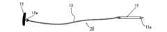
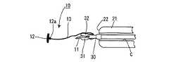
まず、図1を参照して、磁気アンカー装置10の構成について説明する。
磁気アンカー11は、その先端が尖鋭な針部11aとして形成された針状部材であり、全体が強磁性体によって成形されている。磁性体の具体例としては、純鉄、鉄合金のほか、プラチナマグネット、希土類磁石、テルビウム・ディスプロシウム・鉄合金などの磁石がある。
【0026】
ストッパ部材(抜止取付部材)12は、円盤状の部材であり、その一方の面(裏面)には取付金具12aが突設されている。この取付金具12aには、柔軟性を有する連結ひも13の一端が固く結ばれており、連結ひも13の他端は、磁気アンカー11の基端に固く結ばれており、この連結ひも13を介して、ストッパ部材12と磁気アンカー11が連結されている。連結ひも13としては、例えば、手術用縫合糸、釣糸、金属製ワイヤを使用することができる。
【0027】
図2は、磁気アンカー誘導システムを用いた切除術の実施に用いる内視鏡20を示している。
内視鏡20の構造は公知なので詳しい説明は省略するが、体内に挿入される挿入部21の先端面22には、エア及び洗浄水を送るための送気送水ノズル(図示略)、切除部及びその周辺を照らすための照明窓(図示略)、切除部及びその周辺を観察するとともに、直後に対物レンズが配置された観察窓(いずれも図示略)、並びに、鉗子チャネルCの出口23(図10、図11等参照)が設けられている。鉗子チャンネルCは挿入部21内に形成されており、その入口24aは鉗子挿入口突起24の端面に形成されている。この鉗子チャンネルCの出口23の直径は、ストッパ部材12の直径より小さい。
【0028】
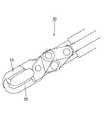
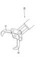
図3及び図4等に示す把持鉗子30は、内視鏡20の鉗子チャンネルC内に挿脱されるものである。
把持鉗子30は、その先端に開閉可能な一対の把持爪31、32を具備しており、その基端に設けられた操作部(図示略)を操作することにより、把持爪31、32は、図3に示す全閉状態と図4に示す全開状態との間を開閉移動する。
【0029】
次に、図5及び図6を用いて、患者Aの体外において磁気アンカー11を吸引制御する磁気アンカー誘導装置40の構成について説明する。
患者Aを載せる床板41aを具備するベッド41の両側部には、一対のXYステージ(一方向移動機構)42、42が配設されている。この一対のXYステージ42は、ベッド41の長手方向に沿って、両者42、42の該長手方向位置が常時同じになるように、直線的に往復移動するものである。さらに、ベッド41の上方には、ベッド41の長手方向と直交する平面内において互いに平行をなす、正面視略逆U字形の二つのレール44、45からなるフレーム/レール(一平面内移動機構)43が配設されており、このフレーム/レール43の両端部は、左右のXYステージ42にそれぞれ固定されている。内側のレール44には、磁気アンカー装置10の磁気アンカー11を体外において吸引制御する(磁気アンカー11に磁力を及ぼす)磁気誘導部材46が摺動自在に装着されており、磁気誘導部材46は左右のXYステージ42の間を、レール45に沿って移動することができる。磁気誘導部材46は、鉄心にコイルを巻いた構造の電磁石47を基体48上に固定したものであり、その電磁石47は常時、患者A側を向いている(図5参照)。なお、磁気誘導部材46は、永久磁石と電磁石の組み合わせでもよく、また、永久磁石と電磁石を2個以上組み合わせたものでも良い。
【0030】
フレーム/レール43の外側のレール45には、フレーム/レール43全体の重量バランスを保つためのカウンターウエイト49がレール45に摺動自在に装着されている。カウンターウエイト49は、磁気誘導部材46の位置に応じて、その位置を変更する。例えば、磁気誘導部材46が患者Aの正面側に位置するときは、カウンターウエイト49は患者Aの背面側に位置し、磁気誘導部材46が患者Aの背面側にあるときは、カウンターウエイト49は患者Aの正面側に位置して、フレーム/レール43全体の重量バランスをとっている。
そして、以上説明した磁気誘導部材46、XYステージ42、フレーム/レール43により磁気アンカー誘導装置40が構成されている。
【0031】
次に、磁気アンカー誘導システムを用いた病変部Xの切除要領について説明する。
磁気アンカー誘導システムを用いた切除術の実施に先立っては、まず、図5及び図6に示すように、局所麻酔を施した患者Aをベッド41の床板41a上に横たわらせる。このとき、XYステージ42を操作して、フレーム/レール43のベッド41の長手方向位置を、患者Aの頭部A1とほぼ同じ位置にしておき、さらに、磁気誘導部材46及びカウンターウエイト49を所定の場所に位置させておく。
次に、XYステージ42を操作してフレーム/レール43を患者Aの正面側に配置させ、さらに、磁気誘導装置46をフレーム/レール43に沿って移動させて、磁気誘導部材46を切除術開始時位置に位置させる(図6参照)。
【0032】
次いで、図示を省略した可撓性を有するオーバーチューブを、患者Aの口から体内に挿入し、このオーバーチューブの先端部を、臓器B(図11、図15及び図16参照)(対象物)内の病変部Xに近接させる。そして、内視鏡20をオーバーチューブ内に挿入し、挿入部21の先端部をオーバーチューブの先端から突出させ、病変部Xに近接させる(図示略)。このように、内視鏡20の挿入部21の先端を臓器B内に挿入すると、内視鏡20の観察窓から得られた臓器B内の観察像が、図示を省略したテレビモニタに写し出される。
【0033】
次いで、鉗子挿入口突起24の入口24aから、先端部に注射針を具備するチューブ状の処置具(図示略)を挿入し、その注射針を挿入部21の出口23から突出させて、注射針を病変部Xの周辺から臓器壁の粘膜下層B1に挿入して生理食塩水を注入し、病変部Xを固有筋層B2から浮き上がらせておく。
次いで、内視鏡20の鉗子チャンネルCに、図12に示すような高周波メス50(図12では内視鏡20の図示は省略)を挿入し、その先端50aにより、病変部X近傍の粘膜に切り込みを入れ、病変部X近傍に舌状粘膜(対象部位)Yを形成する(図12、図15及び図16参照)。
【0034】
次に、内視鏡20を患者Aの体内から取り出すとともに、鉗子チャンネルCから高周波メス50を取り出し、鉗子チャンネルCに把持鉗子30を挿入し、その先端を内視鏡20の先端面22から突出させる。
続いて、図7に示す磁性体からなる磁気シートSを、図8に示すように丸めた状態にする。そして、図9に示すように、内視鏡20(図9では図示略)の先端から突出した把持鉗子30の把持爪31、32で把持し、鉗子挿入口突起24から後方に突出している把持鉗子30の基端部(図示略)を後方に牽引して、図10に示すように、磁気シートSを鉗子チャンネルC内に完全に収納する。全開状態における磁気シートS(図7の状態)の面積は、磁気誘導部材46から発生する磁界中の磁束の臓器Bと交わる位置での断面積より大きく設定されている。
【0035】
次いで、図11に示すように、内視鏡20の挿入部21を再び臓器B内に挿入し、把持鉗子30の先端を内視鏡20から突出させ、患者Aの体外に配設されている磁気誘導部材46(図11では図示略)の発生磁界を強める。そして、把持爪31、32を開いて、把持爪31、32から磁気シートSを解放すると、、磁気誘導装置46から発生する磁力によって、磁気シートSが図11及び図12の上方に移動して臓器Bの内壁に吸引され(図12参照)るとともに磁化され、磁気シートSの全面から磁界が発生する。この結果、臓器B内に、磁気誘導装置46から発生する磁界よりも大きい磁界を、発生させることができる。
【0036】
次に、図13に示すように、再び内視鏡20を患者Aの体内から取り出し、把持鉗子30の把持爪31、32により、磁気アンカー装置10の磁気アンカー11を把持する。さらに、把持鉗子30の基端部を後方に牽引して、図14に示すように、把持爪31、32と磁気アンカー11と連結ひも13を鉗子チャンネルC内に収納し、ストッパ部材12の裏面を、挿入部21の先端面22に当接させる。
【0037】
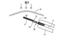
そして、図15に示すように、再び内視鏡20の挿入部21を臓器B内に挿入し、把持鉗子30を内視鏡20に対して相対移動させることにより、把持爪31、32と連結ひも13とストッパ部材12を、臓器B内に押し出す。さらに、把持鉗子30を操作して、磁気アンカー11の針部11aを舌状粘膜Yに突き刺し、舌状粘膜Yを貫通させる。磁気アンカー11の針部11aが舌状粘膜Yの反対側(図15の上側)に突出したら、把持爪31、32から磁気アンカー11を一旦解放し、舌状粘膜Yの反対側に突出している磁気アンカー11の先端側を把持爪31、32で再び把持し、把持鉗子30を移動させて、磁気アンカー11を舌状粘膜Yの磁気シートS側に完全に貫通させる。すると、磁気シートSから発生する磁力によって、磁気アンカー11は磁気シートS側に引き寄せられるので、連結ひも13が緊張して、舌状粘膜Yが磁気アンカー側に移動させられる。そしてこの際、把持鉗子30を操作して、磁気アンカー11を磁気シートSの所定の位置に誘導して接触させると、磁気シートSから発生する磁力によって、磁気アンカー11はその位置に保持される。
【0038】
さらに、内視鏡20を患者Aの体外に取り出し、上記と同じ要領により、別に用意してある磁気アンカー装置10を内視鏡20に装着して、上記と同じ要領により、この磁気アンカー11を舌状粘膜Yに貫通させ、さらに磁気シートSの所定の位置に接触させる。図16に示すように、本実施形態では、計3個の磁気アンカー装置10を用いている。
【0039】
このように、3個の磁気アンカー装置10の各磁気アンカー11を、磁気シートSの異なる箇所にそれぞれ接触保持させると、舌状粘膜Yには、各磁気アンカー装置10の連結ひも13に生じる張力の合力が掛かる。そのため、各磁気アンカー11の磁気シートSとの接触位置を、把持鉗子30を用いて変更して、上記合力を変化させることにより、舌状粘膜Yを所定の方向に所定の距離だけ移動させることができる。
【0040】
そして、舌状粘膜Yを所定の方向に所定の距離だけ移動させると、病変部Xが所望方向に所望距離だけ確実に移動するので、病変部Xと正常組織との境界部には、十分な大きさの切除部分が形成される。このため、高周波メス50(図16では図示略)により、病変部Xを粘膜とともに一方の端部側から切除することができ、高周波メス50が反対側の端部に達すると、病変部Xは粘膜から完全に切除される(図示略)。
なお、高周波メス50による切除作業時においては、切除領域が拡がるにつれて、高周波メス50の先端50aの位置の確認は、より容易となる。
【0041】
以上のように切除作業を終えると、正常組織から切り離された病変部Xは磁気アンカー装置10との一体状態を維持するので、病変部Xが紛失することが防止される。切除した病変部Xを回収するには、内視鏡20の鉗子チャンネルCから高周波メス50を引き抜いた後、把持鉗子30を再び鉗子チャンネルCに挿入し、把持鉗子30により、いずれかの磁気アンカー11を把持し、そのままの状態で内視鏡20を体内から抜き去り、病変部Xを磁気アンカー装置10とともに体外に取り出す。その後に、切除した部分の縫合、消毒などの処置を行う。
【0042】
このように本実施形態では、磁気シートSを用いて、この磁気シートS全面から磁界を発生させ、各磁気アンカー11を磁気シートSの所定位置に接触させることにより、病変部Xの移動方向や移動距離を、精度よく調整することできる。
なお、磁気シートSの面積をさらに広くすれば、病変部Xの移動方向や移動距離を、さらに精度よく調整することが可能となる。
【0043】
また、病変部Xを所望方向に十分な距離だけ移動させることができるため、病変部Xと正常組織との境界の切除部分を、容易かつ確実に十分な大きさで確保することができ、また、病変部Xが扁平な形状であっても、十分な大きさの切除部分を作りだすことができるので、病変部Xを容易に切除することが可能となる。
【0044】
さらに、病変部Xは貫通取付部材12により持ち上げられるため、切除部分を十分確保することができ、すでに切除した病変部Xが固有筋層B2上に落ち込むことを防止できる。
また、任意の位置にストッパ部材12と連結ひも13を配置できるため、切除した病変部Xにより内視鏡20の視界が妨げられることがない。
【0045】
また、磁気アンカー11は針状部材なので舌状粘膜Yをスムーズに貫通することができ、しかも、磁気アンカー11と連結ひも13が舌状粘膜Yを貫通すると、ストッパ部材12により、磁気アンカー11及び連結ひも13が舌状粘膜Yから確実に抜け止めされるので、磁気シートSから発生する磁界を強めても、磁気アンカー装置10が舌状粘膜Yから抜け出すことを確実に防止できる。
【0046】
なお、磁気誘導部材46を移動させると、磁気シートSの位置も変化するので、このようにしても、舌状粘膜Yの移動方向や移動距離を調整することができる。
【0047】
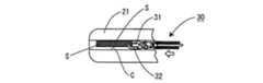
次に、本発明の第2の実施形態について、図17を参照しながら説明する。
なお、第1の実施形態と同じ部材には同じ符号を付すに止めて、その詳細な説明は省略する。
【0048】
本実施形態の磁気アンカー装置60の強磁性体からなる磁気アンカー61は、その先端が尖鋭な針部61aとなっており、かつ、把持鉗子30の把持爪31、32で把持しやすくするための把持用孔61bを有している。
また、ストッパ部材(抜止取付部材)62は、第1の実施形態のストッパ部材12が具備していた取付金具12aを具備しておらず、ストッパ部材62に連結ひも13の一端が直接固着されている。
【0049】
この磁気アンカー装置60は、第1の実施形態と同じ要領により、内視鏡20を用いて臓器B内に挿入されるとともに、磁気アンカー61が把持鉗子30によって舌状粘膜Yを貫通し、磁気シートSの所定の位置に接触保持される。
【0050】
このように本実施形態の磁気アンカー誘導システムによっても、第1の実施形態と同様の効果を奏するとともに、磁気アンカー61が把持鉗子30によって把持し易くなっているので、磁気アンカー61の舌状粘膜Yへの貫通操作や磁気シートSへの誘導操作を、第1の実施形態に比べて容易に行うことができる。
【0051】
以上、本発明について上記実施形態を参照しつつ説明したが、本発明は上記実施形態に限定されるものではなく、改良の目的または本発明の思想の範囲内において改良または変更が可能である。例えば、図18に示すように、ストッパ部材(抜止取付部材)72をリング状のものとし、把持鉗子30の把持爪31、32により把持し易くしてもよい。また、磁気シートSを永久磁石からなるなるものとしてもよい。
【0052】
【発明の効果】
以上説明したように、本発明によると、磁気アンカーを所望の方向に精度よく移動させることができるとともに、磁気アンカーと連結された抜止取付部材を、対象物内部の対象部位にスムーズに貫通させることができ、しかも貫通後には確実に抜け止めすることが可能となる。
【図面の簡単な説明】
【図1】本発明の第1の実施形態の磁気アンカー装置の全体図である。
【図2】内視鏡の全体図である。
【図3】把持爪が閉じた状態の把持鉗子の先端部を示す図である。
【図4】把持爪が開いた状態の把持鉗子の先端部を示す図である。
【図5】病変部の切除が行われる患者を載せたベッドと、磁気アンカー誘導装置を、患者の頭部側から見た図である。
【図6】患者を載せたベッドと、磁気アンカー誘導装置の側面図である。
【図7】磁気シート全体を示す斜視図である。
【図8】磁気シートを巻回した状態を示す図である。
【図9】内視鏡の鉗子チャンネルに挿入された把持鉗子が、内視鏡の外部において、磁気シートを把持している状態を示す図である。
【図10】内視鏡の鉗子チャンネルに挿入された把持鉗子が、磁気シートを把持したまま、鉗子チャンネル内に引き込まれている状態を、内視鏡を断面視して示す図である。
【図11】内視鏡により、巻回された状態の磁気シートを臓器内に挿入した状態を示す図である。
【図12】臓器の壁に磁気シートが吸引されるとともに、高周波メスにより臓器内の粘膜に舌状粘膜を形成する様子を示す図である。
【図13】内視鏡の鉗子チャンネルに挿入された把持鉗子が、磁気アンカー装置を把持した状態を、内視鏡を断面視して示す図である。
【図14】内視鏡の鉗子チャンネルに挿入された把持鉗子を基端側に牽引することにより、磁気アンカーと連結ひもを鉗子チャンネル内に引き込んだ状態を、内視鏡を断面視して示す図である。
【図15】把持鉗子に把持された磁気アンカーが、臓器の患部近傍に形成された舌状粘膜に接近した状態を示す図である。
【図16】3個の磁気アンカー装置の磁気アンカーを舌状粘膜に貫通させて、磁気シートに接触させた後に、磁気アンカー誘導装置を用いて、磁気アンカーを磁気シートに接触保持し、舌状粘膜を牽引している状態を示す図である。
【図17】本発明の第2の実施形態の磁気アンカー装置の全体図である。
【図18】ストッパ部材の変形例を示す正面図である。
【符号の説明】
10 磁気アンカー装置
11 磁気アンカー
11a 針部
12 ストッパ部材(抜止取付部材)
12a 取付金具
13 連結ひも
20 内視鏡
21 挿入部
22 先端面
23 鉗子チャンネルの出口
24 鉗子挿入口突起
24a 入口
30 把持鉗子
31 把持爪
32 把持爪
40 磁気アンカー誘導装置
41 ベッド
41a 床板
42 XYステージ(一方向移動機構)
43 フレーム/レール(一平面内移動機構)
44 レール
45 レール
46 磁気誘導部材
47 電磁石
48 基体
49 カウンターウェイト
50 高周波メス
50a 先端
60 磁気アンカー装置
61 磁気アンカー
61a 針部
61b 把持用孔
62 ストッパ部材(抜止取付部材)
72 ストッパ部材(抜止取付部材)
A 患者
A1 頭部
B 臓器(対象物)
B1 粘膜下層
B2 固有筋層
C 鉗子チャンネル
S 磁気シート
X 病変部
Y 舌状粘膜(対象部位)[0001]
【Technical field】
The present invention relates to a magnetic anchor guidance system for an endoscope and a treatment method using an endoscope using the magnetic anchor guidance system, which are used when a lesion is resected under endoscopic observation.
[0002]
[Prior art and its problems]
Conventionally, when removing a lesion inside the human body during normal surgery, the distance between the lesion and the adjacent normal tissue is increased by lifting the lesion using grasping forceps, and in that state, the lesion and the normal Resection between tissue. However, for example, in endoscopic mucosal resection (EMR), only one endoscope can be inserted into the body, so that the lesion cannot be lifted. The lesion was lifted by injecting saline, and in that state, resection between the lesion and the normal mucosa was performed using a high-frequency knife or snare.
[0003]
However, in such a conventional method, the lesion cannot be lifted to a sufficient position, so that a resection at the boundary between the lesion and normal tissue cannot be sufficiently secured.
Also, when the lesion has a flat shape, it may not be possible to create a resected portion.
[0004]
Furthermore, during the resection operation, the already resected lesion may fall on the normal tissue, thereby obstructing the endoscope's field of view, particularly when the lesion is large. Because of this, the resected part cannot be seen, and the normal part is damaged to perform a blind resection, resulting in complications such as perforation, damage to blood vessels, and major bleeding. Serious complications may occur due to inability to confirm and prevent hemostasis, and safer devices and treatment methods have been required.
[0005]
Therefore, the present applicant, in order to solve these problems, a clip for grasping a lesion in an organ inside a human body, a magnetic anchor made of a magnetic body connected to the clip, and placed outside the human body, And a magnetic anchor guide device that generates a magnetic field to power the magnetic anchor. The magnetic anchor generates power to the magnetic anchor by a magnetic field generated by the magnetic anchor guide device, so that a target portion (lesion portion or the like) gripped by the clip is removed. A magnetic anchor guidance system characterized by lifting is proposed and patent application is filed (Japanese Patent Application No. 2002-268239).
[0006]
With this magnetic anchor guidance system, a cut is made in the mucous membrane around the lesion to form a tongue mucosa, the tongue mucosa is gripped by a plurality of clips, and a magnetic anchor is attached to each clip via a connecting string. The plurality of magnetic anchors can be connected and moved by a magnetic field generated by the magnetic anchor guiding device. As described above, by moving each magnetic anchor in a desired direction by using a plurality of magnetic anchors, the tongue-shaped mucous membrane can be lifted in a desired direction.
[0007]
However, as described above, since the magnetic anchor has the property of being attracted to the magnetic field, if the cross-sectional area at the position where the magnetic flux in the magnetic field intersects the built-in wall is small, all the magnetic anchors concentrate in a narrow area of the built-in wall. Resulting in. Therefore, it is difficult to move each magnetic anchor in a desired direction, and as a result, it is difficult to lift the tongue-shaped mucous membrane in a desired direction.
[0008]
Further, since the gripping force of the clip used in this patent application is not so large, when the power applied to the magnetic anchor is large, the clip may come off the tongue-shaped mucous membrane. When the clip comes off from the lesion as described above, it is necessary to grip the lesion again with the clip, so that it takes a long time to work on the lesion, and the burden on the operator and the patient increases. I will.
[0009]
[Object of the invention]
An object of the present invention is to allow a magnetic anchor to be accurately moved in a desired direction, and to allow a retaining attachment member connected to a magnetic anchor to smoothly penetrate into a target portion inside a target object, and furthermore, to penetrate. An object of the present invention is to provide a magnetic anchor guiding system for an endoscope, which can be surely retained later, and a treatment method using an endoscope using the magnetic anchor guiding system.
[0010]
Summary of the Invention
A magnetic anchor guidance system for an endoscope according to the present invention includes a retaining attachment member attached to a target portion inside an object, a magnetic anchor made of a magnetic material connected to the retaining attachment member, and a magnetic anchor disposed in the object. A magnetic sheet made of a magnetic material, and a magnetic anchor guide device arranged outside the object to generate a magnetic field, wherein the magnetic sheet is moved inside the object by the magnetic field generated from the magnetic anchor guide device. The magnetic anchor is attracted and held by the magnetic sheet by a magnetic field generated from the entire surface of the magnetic sheet, and the target portion is moved in a predetermined direction.
[0011]
It is preferable to make the area of the magnetic sheet larger than a cross-sectional area of a magnetic flux generated from the magnetic anchor guiding device at a position where the magnetic sheet intersects the object.
[0012]
The magnetic anchor is in the form of a needle that can penetrate the target site, the magnetic anchor and the retaining attachment member are connected together with the magnetic anchor by a flexible connecting string that penetrates the target site, and the retaining attachment member is It is practical to comprise a stopper member for preventing the connecting string from coming off the target portion.
[0013]
Further, it is preferable that a plurality of connecting bodies between the retaining attachment member and the magnetic anchor are provided.
[0014]
The magnetic anchor guiding device generates a magnetic force by a generated magnetic field, and moves the magnetic anchor in a predetermined direction by the magnetic force; and a U-shaped member in which the magnetic guiding member is arranged in a specific plane. It is practical to have an in-plane moving mechanism for moving along the frame member, and a one-way moving mechanism for relatively moving the U-shaped frame member in a direction perpendicular to the one plane.
[0015]
Further, the magnetic anchor can be inserted into and removed from a forceps channel of an endoscope, and while grasping the magnetic anchor, penetrate the magnetic anchor through the target site, and guide the magnetic anchor to a predetermined position of the magnetic sheet. It is preferred to have a grasping forceps that can be used.
[0016]
A treatment method using an endoscope using the magnetic anchor guidance system of the present invention includes the steps of: disposing a magnetic sheet made of a magnetic material inside the object; An attaching step of attaching the retaining attachment member connected to the anchor in a state where it is prevented from being removed, a step of generating a magnetic field by a magnetic anchor guiding device arranged outside the object and moving the magnetic sheet, and an entire surface of the magnetic sheet Moving the magnetic anchor to the magnetic sheet side by the magnetic force generated from the magnetic sheet and moving the target portion.
[0017]
It is preferable to make the area of the magnetic sheet larger than a cross-sectional area of a magnetic flux generated from the magnetic anchor guiding device at a position where the magnetic sheet intersects the object.
[0018]
Preferably, the method further includes a guiding step of guiding the magnetic anchor to a predetermined position on the magnetic sheet.
[0019]
Further, the magnetic anchor has a needle shape that can penetrate the target site, and the magnetic anchor and the retaining attachment member are connected together with the magnetic anchor by a flexible connecting string that penetrates the target site. It is preferable that the retaining attachment member comprises a stopper member for preventing the connecting cord from coming off the target portion.
[0020]
Further, in the attaching step, it is practical to attach the plurality of retaining attachment members to a target portion inside the target object.
[0021]
Further, it is practical that the attaching step is a step in which the needle-shaped magnetic anchor penetrates the target portion and the retaining member is brought into contact with the target portion.
[0022]
Before the attaching step, a step of inserting a grasping forceps having a grasping claw that can be freely opened and closed at a distal end into a forceps channel of the endoscope, a step of grasping the needle-shaped magnetic anchor with the grasping claws, and By moving the endoscope, the insertion step of inserting the needle-shaped magnetic anchor into the object, and further, the mounting step, the needle-shaped magnetic anchor to the target site by the gripping forceps It is practical to be the step of penetrating.
[0023]
Further, it is practical that the guiding step is a step of guiding the needle-shaped magnetic anchor to a predetermined position on the magnetic sheet by the gripping forceps.
[0024]
BEST MODE FOR CARRYING OUT THE INVENTION
Hereinafter, a first embodiment of the present invention will be described with reference to FIGS.
The magnetic anchor guiding system according to the present embodiment controls the magnetic anchor device 10 (the
[0025]
First, the configuration of the
The
[0026]
The stopper member (prevention mounting member) 12 is a disk-shaped member, and a mounting
[0027]
FIG. 2 shows an
Since the structure of the
[0028]
The grasping
The grasping
[0029]
Next, the configuration of the magnetic
A pair of XY stages (one-way moving mechanisms) 42, 42 are arranged on both sides of a
[0030]
A
The
[0031]
Next, a procedure for excision of the lesion X using the magnetic anchor guiding system will be described.
Prior to performing the resection using the magnetic anchor guiding system, first, as shown in FIGS. 5 and 6, the patient A who has been subjected to local anesthesia is laid on the
Next, the
[0032]
Next, a flexible overtube (not shown) is inserted into the body through the mouth of the patient A, and the distal end of the overtube is inserted into the organ B (see FIGS. 11, 15 and 16) (object). Close to the lesion X in the inside. Then, the
[0033]
Next, a tubular treatment tool (not shown) having an injection needle at the distal end is inserted from the
Next, a high-frequency scalpel 50 (illustration of the
[0034]
Next, the
Subsequently, the magnetic sheet S made of a magnetic material shown in FIG. 7 is rolled as shown in FIG. Then, as shown in FIG. 9, the
[0035]
Next, as shown in FIG. 11, the
[0036]
Next, as shown in FIG. 13, the
[0037]
Then, as shown in FIG. 15, the
[0038]
Further, the
[0039]
As described above, when the
[0040]
When the tongue-shaped mucous membrane Y is moved by a predetermined distance in a predetermined direction, the lesion X is surely moved by a desired distance in a desired direction. A cut-out of size is formed. For this reason, the lesion X can be resected together with the mucous membrane from one end by the high-frequency knife 50 (not shown in FIG. 16), and when the high-
During the cutting operation using the high-
[0041]
When the resection operation is completed as described above, the lesion X separated from the normal tissue maintains an integrated state with the
[0042]
As described above, in the present embodiment, the magnetic sheet S is used to generate a magnetic field from the entire surface of the magnetic sheet S, and each
If the area of the magnetic sheet S is further increased, the moving direction and the moving distance of the lesion X can be adjusted with higher accuracy.
[0043]
In addition, since the lesion X can be moved in the desired direction by a sufficient distance, a cut portion at the boundary between the lesion X and normal tissue can be easily and reliably secured in a sufficient size. Even if the lesion X has a flat shape, a sufficiently large resection can be made, so that the lesion X can be easily resected.
[0044]
Furthermore, since the lesion X is lifted by the penetrating
In addition, since the
[0045]
Further, since the
[0046]
When the magnetic guiding
[0047]
Next, a second embodiment of the present invention will be described with reference to FIG.
The same members as those in the first embodiment are denoted by the same reference numerals, and detailed description thereof is omitted.
[0048]
The
In addition, the stopper member (prevention mounting member) 62 does not include the mounting
[0049]
The
[0050]
As described above, according to the magnetic anchor guiding system of the present embodiment, the same effects as those of the first embodiment can be obtained, and the
[0051]
As described above, the present invention has been described with reference to the above embodiments. However, the present invention is not limited to the above embodiments, and can be improved or changed within the scope of the purpose of improvement or the concept of the present invention. For example, as shown in FIG. 18, the stopper member (removal attachment member) 72 may be formed in a ring shape, and may be easily grasped by the grasping
[0052]
【The invention's effect】
As described above, according to the present invention, the magnetic anchor can be accurately moved in a desired direction, and the retaining attachment member connected to the magnetic anchor can be smoothly penetrated into the target portion inside the target object. And it is possible to reliably prevent it from coming off after penetration.
[Brief description of the drawings]
FIG. 1 is an overall view of a magnetic anchor device according to a first embodiment of the present invention.
FIG. 2 is an overall view of an endoscope.
FIG. 3 is a diagram illustrating a distal end portion of a grasping forceps in a state where a grasping claw is closed.
FIG. 4 is a diagram showing a distal end portion of the grasping forceps with the grasping claws open.
FIG. 5 is a view of a bed on which a patient from which a lesion is to be resected is placed and a magnetic anchor guiding device as viewed from the patient's head side.
FIG. 6 is a side view of a bed on which a patient is placed and a magnetic anchor guiding device.
FIG. 7 is a perspective view showing the entire magnetic sheet.
FIG. 8 is a diagram showing a state in which a magnetic sheet is wound.
FIG. 9 is a diagram showing a state in which a grasping forceps inserted into a forceps channel of the endoscope is gripping a magnetic sheet outside the endoscope.
FIG. 10 is a cross-sectional view of the endoscope, showing a state in which the grasping forceps inserted into the forceps channel of the endoscope is drawn into the forceps channel while holding the magnetic sheet.
FIG. 11 is a diagram showing a state where a wound magnetic sheet is inserted into an organ by an endoscope.
FIG. 12 is a diagram showing a state in which a magnetic sheet is attracted to a wall of an organ and a tongue-shaped mucous membrane is formed on a mucous membrane in the organ by a high-frequency scalpel.
FIG. 13 is a cross-sectional view of the endoscope, showing a state in which the gripping forceps inserted into the forceps channel of the endoscope grips the magnetic anchor device.
FIG. 14 is a cross-sectional view of the endoscope, showing a state in which the magnetic anchor and the connecting string are pulled into the forceps channel by pulling the grasping forceps inserted into the forceps channel of the endoscope to the proximal end side. FIG.
FIG. 15 is a view showing a state where the magnetic anchor gripped by the gripping forceps approaches a tongue-shaped mucous membrane formed near the affected part of the organ.
FIG. 16 shows a state in which the magnetic anchors of the three magnetic anchor devices penetrate the tongue-shaped mucous membrane and come into contact with the magnetic sheet. It is a figure which shows the state which is pulling a mucous membrane.
FIG. 17 is an overall view of a magnetic anchor device according to a second embodiment of the present invention.
FIG. 18 is a front view showing a modification of the stopper member.
[Explanation of symbols]
43 frame / rail (moving mechanism within one plane)
44
72 Stopper member (prevention attachment member)
A patient A1 head B organ (object)
B1 submucosal layer B2 proper muscle layer C forceps channel S magnetic sheet X lesion Y tongue mucosa (target site)
Claims (14)
Translated fromJapanese該抜止取付部材に接続された磁性体からなる磁気アンカーと、
上記対象物内に配置される磁性体からなる磁気シートと、
上記対象物外部に配置され、磁界を発生させる磁気アンカー誘導装置と、
を備え、
上記磁気アンカー誘導装置から発生する磁界により上記磁気シートを上記対象物内部で移動させ、該磁気シート全面から生じる磁界により該磁気シートに上記磁気アンカーを吸引保持させて、上記対象部位を所定方向に移動させることを特徴とする内視鏡用磁気アンカー誘導システム。A retaining attachment member attached to a target portion inside the target object,
A magnetic anchor made of a magnetic material connected to the retaining member,
A magnetic sheet made of a magnetic material disposed in the object,
A magnetic anchor guidance device arranged outside the object to generate a magnetic field,
With
The magnetic sheet is moved inside the object by a magnetic field generated from the magnetic anchor guiding device, and the magnetic sheet is sucked and held by the magnetic sheet by a magnetic field generated from the entire surface of the magnetic sheet. A magnetic anchor guidance system for an endoscope, which is moved.
上記抜止取付部材と上記磁気アンカーとの接続体を、複数備えている内視鏡用磁気アンカー誘導システム。The magnetic anchor guidance system for an endoscope according to any one of claims 1 to 3,
A magnetic anchor guiding system for an endoscope, comprising a plurality of connectors of the retaining attachment member and the magnetic anchor.
上記磁気アンカー誘導装置は、
発生する磁界によって磁力を生じさせて、該磁力によって、上記磁気アンカーを所定方向に移動させる磁気誘導部材と、
該磁気誘導部材を特定の一平面内に配置したU字状のフレーム部材に沿って移動させる一平面内移動機構と、
上記U字状のフレーム部材を上記一平面と直交する方向に相対移動させる一方向移動機構と、
を有する内視鏡用磁気アンカー誘導システム。The magnetic anchor guidance system for an endoscope according to any one of claims 1 to 4,
The magnetic anchor guiding device,
A magnetic induction member that generates a magnetic force by the generated magnetic field and moves the magnetic anchor in a predetermined direction by the magnetic force;
An in-plane moving mechanism for moving the magnetic guide member along a U-shaped frame member arranged in a specific plane;
A one-way moving mechanism for relatively moving the U-shaped frame member in a direction perpendicular to the one plane,
A magnetic anchor guidance system for an endoscope having a.
さらに、
内視鏡の鉗子チャンネルに挿脱可能であるとともに、
上記磁気アンカーを把持しながら、該磁気アンカーを上記対象部位に貫通させ、かつ、該磁気アンカーを上記磁気シートの所定位置に誘導することができる把持鉗子を具備する内視鏡用磁気アンカー誘導システム。The magnetic anchor guidance system for an endoscope according to claim 5,
further,
It can be inserted into and removed from the forceps channel of the endoscope,
A magnetic anchor guiding system for an endoscope including gripping forceps capable of penetrating the magnetic anchor through the target site while gripping the magnetic anchor, and guiding the magnetic anchor to a predetermined position on the magnetic sheet. .
上記対象物内部の対象部位に、磁性体からなる磁気アンカーに接続されている抜止取付部材を抜け止めされた状態で取り付ける取付ステップ、
対象物外部に配置された磁気アンカー誘導装置により磁界を発生させ、上記磁気シートを移動させるステップ、及び
上記磁気シート全面から発生する磁力により、上記磁気アンカーを、該磁気シート側に移動させて、上記対象部位を移動させるステップ、
を有することを特徴とする磁気アンカー誘導システムを用いた内視鏡による処置方法。Disposing a magnetic sheet made of a magnetic material inside the object;
Attachment step of attaching the retaining attachment member connected to the magnetic anchor made of a magnetic body to the target portion inside the target object in a state where it is retained,
A magnetic field is generated by a magnetic anchor guiding device disposed outside the object, the step of moving the magnetic sheet, and the magnetic force generated from the entire magnetic sheet, the magnetic anchor is moved to the magnetic sheet side, Moving the target site,
A treatment method using an endoscope using a magnetic anchor guidance system, comprising:
上記磁気アンカーを上記磁気シートの所定位置に誘導する誘導ステップを有する、磁気アンカー誘導システムを用いた内視鏡による処置方法。An endoscopic treatment method using the magnetic anchor guidance system according to claim 7 or 8, further comprising:
A treatment method by an endoscope using a magnetic anchor guiding system, the method including a guiding step of guiding the magnetic anchor to a predetermined position of the magnetic sheet.
上記取付ステップでは、複数の上記抜止取付部材を上記対象物内部の対象部位に取り付ける磁気アンカー誘導システムを用いた内視鏡による処置方法。An endoscopic treatment method using the magnetic anchor guidance system according to any one of claims 7 to 10,
In the attaching step, a treatment method using an endoscope using a magnetic anchor guiding system for attaching the plurality of retaining attachment members to a target site inside the target object.
上記取付ステップは、上記針状の磁気アンカーを対象部位に貫通させ、上記抜止取付部材を上記対象部位に当接させるステップである、磁気アンカー誘導システムを用いた内視鏡による処置方法。A treatment method using an endoscope using the magnetic anchor guidance system according to any one of claims 7 to 11,
The attachment method is a treatment method using an endoscope using a magnetic anchor guidance system, wherein the needle-shaped magnetic anchor penetrates a target portion and the retaining attachment member contacts the target portion.
上記取付ステップの前に、
内視鏡の鉗子チャンネルに、先端に開閉自在な把持爪を有する把持鉗子を挿入するステップ、
該把持爪により、上記針状の磁気アンカーを把持するステップ、及び
上記内視鏡を移動させることによって、上記針状の磁気アンカーを対象物内部に挿入する挿入ステップ、
を有し、さらに、
上記取付ステップが、
上記把持鉗子により上記針状の磁気アンカーを上記対象部位に貫通させるステップである、磁気アンカー誘導システムを用いた内視鏡による処置方法。An endoscopic treatment method using the magnetic anchor guidance system according to claim 12, further comprising:
Before the above mounting steps,
Inserting a grasping forceps having a grasping claw that can be freely opened and closed at the tip into a forceps channel of an endoscope,
A step of gripping the needle-shaped magnetic anchor by the gripping claws, and an inserting step of inserting the needle-shaped magnetic anchor into an object by moving the endoscope;
And further,
The above mounting step is
A treatment method using an endoscope using a magnetic anchor guidance system, which is a step of causing the needle-shaped magnetic anchor to penetrate the target site by the grasping forceps.
上記誘導ステップが、上記把持鉗子により上記針状の磁気アンカーを上記磁気シートの所定位置に誘導するステップである、磁気アンカー誘導システムを用いた内視鏡による処置方法。A treatment method using an endoscope using the magnetic anchor guidance system according to claim 13,
A treatment method using an endoscope using a magnetic anchor guiding system, wherein the guiding step is a step of guiding the needle-shaped magnetic anchor to a predetermined position on the magnetic sheet by the gripping forceps.
Priority Applications (1)
| Application Number | Priority Date | Filing Date | Title |
|---|---|---|---|
| JP2003145333AJP4338440B2 (en) | 2003-05-22 | 2003-05-22 | Magnetic guidance means guidance system for endoscope |
Applications Claiming Priority (1)
| Application Number | Priority Date | Filing Date | Title |
|---|---|---|---|
| JP2003145333AJP4338440B2 (en) | 2003-05-22 | 2003-05-22 | Magnetic guidance means guidance system for endoscope |
Publications (2)
| Publication Number | Publication Date |
|---|---|
| JP2004344427Atrue JP2004344427A (en) | 2004-12-09 |
| JP4338440B2 JP4338440B2 (en) | 2009-10-07 |
Family
ID=33532548
Family Applications (1)
| Application Number | Title | Priority Date | Filing Date |
|---|---|---|---|
| JP2003145333AExpired - Fee RelatedJP4338440B2 (en) | 2003-05-22 | 2003-05-22 | Magnetic guidance means guidance system for endoscope |
Country Status (1)
| Country | Link |
|---|---|
| JP (1) | JP4338440B2 (en) |
Cited By (29)
| Publication number | Priority date | Publication date | Assignee | Title |
|---|---|---|---|---|
| US7758594B2 (en) | 2005-05-20 | 2010-07-20 | Neotract, Inc. | Devices, systems and methods for treating benign prostatic hyperplasia and other conditions |
| US7766923B2 (en) | 2005-05-20 | 2010-08-03 | Neotract, Inc. | Integrated handle assembly for anchor delivery system |
| US7780682B2 (en) | 2005-05-20 | 2010-08-24 | Neotract, Inc. | Apparatus and method for manipulating or retracting tissue and anatomical structure |
| US7815655B2 (en) | 2005-05-20 | 2010-10-19 | Neotract, Inc. | Devices, systems and methods for retracting, lifting, compressing, supporting or repositioning tissues or anatomical structures |
| US7909836B2 (en) | 2005-05-20 | 2011-03-22 | Neotract, Inc. | Multi-actuating trigger anchor delivery system |
| JP2011528606A (en)* | 2008-07-21 | 2011-11-24 | アルスタシス,インコーポレイテッド | Apparatus and method for forming a tract in tissue |
| US8216254B2 (en) | 2005-05-20 | 2012-07-10 | Neotract, Inc. | Anchor delivery system with replaceable cartridge |
| US8333776B2 (en) | 2005-05-20 | 2012-12-18 | Neotract, Inc. | Anchor delivery system |
| US8394113B2 (en) | 2005-05-20 | 2013-03-12 | Neotract, Inc. | Coiled anchor device |
| US8425535B2 (en) | 2005-05-20 | 2013-04-23 | Neotract, Inc. | Multi-actuating trigger anchor delivery system |
| US8454655B2 (en) | 2002-03-14 | 2013-06-04 | Neotract, Inc. | Method for anchoring suture and approximating tissue |
| US8603106B2 (en) | 2005-05-20 | 2013-12-10 | Neotract, Inc. | Integrated handle assembly for anchor delivery system |
| US8668705B2 (en) | 2005-05-20 | 2014-03-11 | Neotract, Inc. | Latching anchor device |
| US8758366B2 (en) | 2007-07-09 | 2014-06-24 | Neotract, Inc. | Multi-actuating trigger anchor delivery system |
| US8945152B2 (en) | 2005-05-20 | 2015-02-03 | Neotract, Inc. | Multi-actuating trigger anchor delivery system |
| US9034001B2 (en) | 2005-05-20 | 2015-05-19 | Neotract, Inc. | Slotted anchor device |
| US9149266B2 (en) | 2005-05-20 | 2015-10-06 | Neotract, Inc. | Deforming anchor device |
| US9161749B2 (en) | 2011-04-14 | 2015-10-20 | Neotract, Inc. | Method and apparatus for treating sexual dysfunction |
| US9364212B2 (en) | 2005-05-20 | 2016-06-14 | Neotract, Inc. | Suture anchoring devices and methods for use |
| US9504461B2 (en) | 2005-05-20 | 2016-11-29 | Neotract, Inc. | Anchor delivery system |
| US9549739B2 (en) | 2005-05-20 | 2017-01-24 | Neotract, Inc. | Devices, systems and methods for treating benign prostatic hyperplasia and other conditions |
| US10130353B2 (en) | 2012-06-29 | 2018-11-20 | Neotract, Inc. | Flexible system for delivering an anchor |
| US10195014B2 (en) | 2005-05-20 | 2019-02-05 | Neotract, Inc. | Devices, systems and methods for treating benign prostatic hyperplasia and other conditions |
| US10292801B2 (en) | 2012-03-29 | 2019-05-21 | Neotract, Inc. | System for delivering anchors for treating incontinence |
| US10426509B2 (en) | 2005-05-20 | 2019-10-01 | Neotract, Inc. | Median lobe destruction apparatus and method |
| US10925587B2 (en) | 2005-05-20 | 2021-02-23 | Neotract, Inc. | Anchor delivery system |
| US11298115B2 (en) | 2020-08-03 | 2022-04-12 | Teleflex Life Sciences Limited | Handle and cartridge system for medical interventions |
| US11672520B2 (en) | 2017-12-23 | 2023-06-13 | Teleflex Life Sciences Limited | Expandable tissue engagement apparatus and method |
| US12440301B2 (en) | 2019-10-30 | 2025-10-14 | Teleflex Life Sciences Llc | System for delivery of a fiducial marker |
- 2003
- 2003-05-22JPJP2003145333Apatent/JP4338440B2/ennot_activeExpired - Fee Related
Cited By (66)
| Publication number | Priority date | Publication date | Assignee | Title |
|---|---|---|---|---|
| US8454655B2 (en) | 2002-03-14 | 2013-06-04 | Neotract, Inc. | Method for anchoring suture and approximating tissue |
| US8777992B2 (en) | 2002-03-14 | 2014-07-15 | Neotract, Inc. | Methods for anchoring suture and approximating tissue |
| US9320511B2 (en) | 2005-05-20 | 2016-04-26 | Neotract, Inc. | Multi-actuating trigger anchor delivery system |
| US9486203B2 (en) | 2005-05-20 | 2016-11-08 | Neotract, Inc. | Latching anchor device |
| US7896891B2 (en) | 2005-05-20 | 2011-03-01 | Neotract, Inc. | Apparatus and method for manipulating or retracting tissue and anatomical structure |
| US7905889B2 (en) | 2005-05-20 | 2011-03-15 | Neotract, Inc. | Integrated handle assembly for anchor delivery system |
| US7909836B2 (en) | 2005-05-20 | 2011-03-22 | Neotract, Inc. | Multi-actuating trigger anchor delivery system |
| US7914542B2 (en) | 2005-05-20 | 2011-03-29 | Neotract, Inc. | Devices, systems and methods for treating benign prostatic hyperplasia and other conditions |
| US7951158B2 (en) | 2005-05-20 | 2011-05-31 | Neotract, Inc. | Devices, systems and methods for retracting, lifting, compressing, supporting or repositioning tissues or anatomical structures |
| US8007503B2 (en) | 2005-05-20 | 2011-08-30 | Neotract, Inc. | Apparatus and method for manipulating or retracting tissue and anatomical structure |
| US8043309B2 (en) | 2005-05-20 | 2011-10-25 | Neotract, Inc. | Devices, systems and methods for retracting, lifting, compressing, supporting or repositioning tissues or anatomical structures |
| US12201283B2 (en) | 2005-05-20 | 2025-01-21 | Teleflex Life Sciences Llc | Devices, systems and methods for treating benign prostatic hyperplasia and other conditions |
| US8157815B2 (en) | 2005-05-20 | 2012-04-17 | Neotract, Inc. | Integrated handle assembly for anchor delivery system |
| US8216254B2 (en) | 2005-05-20 | 2012-07-10 | Neotract, Inc. | Anchor delivery system with replaceable cartridge |
| US8333776B2 (en) | 2005-05-20 | 2012-12-18 | Neotract, Inc. | Anchor delivery system |
| US8343187B2 (en) | 2005-05-20 | 2013-01-01 | Neotract, Inc. | Devices, systems and methods for treating benign prostatic hyperplasia and other conditions |
| US8394113B2 (en) | 2005-05-20 | 2013-03-12 | Neotract, Inc. | Coiled anchor device |
| US8425535B2 (en) | 2005-05-20 | 2013-04-23 | Neotract, Inc. | Multi-actuating trigger anchor delivery system |
| US7780682B2 (en) | 2005-05-20 | 2010-08-24 | Neotract, Inc. | Apparatus and method for manipulating or retracting tissue and anatomical structure |
| US8603106B2 (en) | 2005-05-20 | 2013-12-10 | Neotract, Inc. | Integrated handle assembly for anchor delivery system |
| US8663243B2 (en) | 2005-05-20 | 2014-03-04 | Neotract, Inc. | Devices, systems and methods for treating benign prostatic hyperplasia and other conditions |
| US8668705B2 (en) | 2005-05-20 | 2014-03-11 | Neotract, Inc. | Latching anchor device |
| US8715239B2 (en) | 2005-05-20 | 2014-05-06 | Neotract, Inc. | Devices, systems and methods for treating benign prostatic hyperplasia and other conditions |
| US11504149B2 (en) | 2005-05-20 | 2022-11-22 | Teleflex Life Sciences Limited | Median lobe destruction apparatus and method |
| US7766923B2 (en) | 2005-05-20 | 2010-08-03 | Neotract, Inc. | Integrated handle assembly for anchor delivery system |
| US8888799B2 (en) | 2005-05-20 | 2014-11-18 | Neotract, Inc. | Coiled anchor device |
| US8900252B2 (en) | 2005-05-20 | 2014-12-02 | Neotract, Inc. | Devices, systems and methods for treating benign prostatic hyperplasia and other conditions |
| US8939996B2 (en) | 2005-05-20 | 2015-01-27 | Neotract, Inc. | Anchor delivery System |
| US8940001B2 (en) | 2005-05-20 | 2015-01-27 | Neotract, Inc. | Devices, systems and methods for retracting, lifting, compressing, supporting or repositioning tissues or anatomical structures |
| US8945152B2 (en) | 2005-05-20 | 2015-02-03 | Neotract, Inc. | Multi-actuating trigger anchor delivery system |
| US9034001B2 (en) | 2005-05-20 | 2015-05-19 | Neotract, Inc. | Slotted anchor device |
| US9149266B2 (en) | 2005-05-20 | 2015-10-06 | Neotract, Inc. | Deforming anchor device |
| US7815655B2 (en) | 2005-05-20 | 2010-10-19 | Neotract, Inc. | Devices, systems and methods for retracting, lifting, compressing, supporting or repositioning tissues or anatomical structures |
| US11471148B2 (en) | 2005-05-20 | 2022-10-18 | Teleflex Life Sciences Limited | Devices, systems and methods for treating benign prostatic hyperplasia and other conditions |
| US10265061B2 (en) | 2005-05-20 | 2019-04-23 | Neotract, Inc. | Latching anchor device |
| US7758594B2 (en) | 2005-05-20 | 2010-07-20 | Neotract, Inc. | Devices, systems and methods for treating benign prostatic hyperplasia and other conditions |
| US9504461B2 (en) | 2005-05-20 | 2016-11-29 | Neotract, Inc. | Anchor delivery system |
| US9549739B2 (en) | 2005-05-20 | 2017-01-24 | Neotract, Inc. | Devices, systems and methods for treating benign prostatic hyperplasia and other conditions |
| US10105132B2 (en) | 2005-05-20 | 2018-10-23 | Neotract, Inc. | Devices, systems and methods for treating benign prostatic hyperplasia and other conditions |
| US10945719B2 (en) | 2005-05-20 | 2021-03-16 | Neotract, Inc. | Devices, systems and methods for retracting, lifting, compressing, supporting or repositioning tissues or anatomical structures |
| US10143461B2 (en) | 2005-05-20 | 2018-12-04 | Neotract, Inc. | Devices, systems and methods for retracting, lifting, compressing, supporting or repositioning tissues or anatomical structures |
| US10195014B2 (en) | 2005-05-20 | 2019-02-05 | Neotract, Inc. | Devices, systems and methods for treating benign prostatic hyperplasia and other conditions |
| US9364212B2 (en) | 2005-05-20 | 2016-06-14 | Neotract, Inc. | Suture anchoring devices and methods for use |
| US10925587B2 (en) | 2005-05-20 | 2021-02-23 | Neotract, Inc. | Anchor delivery system |
| US10299780B2 (en) | 2005-05-20 | 2019-05-28 | Neotract, Inc. | Apparatus and method for manipulating or retracting tissue and anatomical structure |
| US10575844B2 (en) | 2005-05-20 | 2020-03-03 | Neotract, Inc. | Devices, systems and methods for treating benign prostatic hyperplasia and other conditions |
| US10426509B2 (en) | 2005-05-20 | 2019-10-01 | Neotract, Inc. | Median lobe destruction apparatus and method |
| US10492792B2 (en) | 2005-05-20 | 2019-12-03 | Neotract, Inc. | Devices, systems and methods for treating benign prostatic hyperplasia and other conditions |
| US8758366B2 (en) | 2007-07-09 | 2014-06-24 | Neotract, Inc. | Multi-actuating trigger anchor delivery system |
| JP2011528606A (en)* | 2008-07-21 | 2011-11-24 | アルスタシス,インコーポレイテッド | Apparatus and method for forming a tract in tissue |
| US9161749B2 (en) | 2011-04-14 | 2015-10-20 | Neotract, Inc. | Method and apparatus for treating sexual dysfunction |
| US10292801B2 (en) | 2012-03-29 | 2019-05-21 | Neotract, Inc. | System for delivering anchors for treating incontinence |
| US10130353B2 (en) | 2012-06-29 | 2018-11-20 | Neotract, Inc. | Flexible system for delivering an anchor |
| US11331093B2 (en) | 2012-06-29 | 2022-05-17 | Teleflex Life Sciences Limited | Flexible system for delivering an anchor |
| US12324576B2 (en) | 2012-06-29 | 2025-06-10 | Teleflex Life Sciences Llc | Flexible system for delivering an anchor |
| US12376842B2 (en) | 2012-06-29 | 2025-08-05 | Teleflex Life Sciences Llc | Flexible system for delivering an anchor |
| US11850140B2 (en) | 2013-03-14 | 2023-12-26 | Teleflex Life Sciences Limited | Devices, systems and methods for treating benign prostatic hyperplasia and other conditions |
| US12042372B2 (en) | 2013-03-14 | 2024-07-23 | Teleflex Life Sciences Llc | Devices, systems and methods for treating benign prostatic hyperplasia and other conditions |
| US10912637B2 (en) | 2013-03-14 | 2021-02-09 | Neotract, Inc. | Devices, systems and methods for treating benign prostatic hyperplasia and other conditions |
| US10349932B2 (en) | 2013-03-15 | 2019-07-16 | Neotract, Inc. | Anchor delivery system |
| US11672520B2 (en) | 2017-12-23 | 2023-06-13 | Teleflex Life Sciences Limited | Expandable tissue engagement apparatus and method |
| US12121228B2 (en) | 2017-12-23 | 2024-10-22 | Teleflex Life Sciences Llc | Expandable tissue engagement apparatus and method |
| US12440301B2 (en) | 2019-10-30 | 2025-10-14 | Teleflex Life Sciences Llc | System for delivery of a fiducial marker |
| US11298115B2 (en) | 2020-08-03 | 2022-04-12 | Teleflex Life Sciences Limited | Handle and cartridge system for medical interventions |
| US12167842B2 (en) | 2020-08-03 | 2024-12-17 | Teleflex Life Sciences Llc | Handle and cartridge system for medical interventions |
| US11801041B2 (en) | 2020-08-03 | 2023-10-31 | Teleflex Life Sciences Limited | Handle and cartridge system for medical interventions |
Also Published As
| Publication number | Publication date |
|---|---|
| JP4338440B2 (en) | 2009-10-07 |
Similar Documents
| Publication | Publication Date | Title |
|---|---|---|
| JP4338440B2 (en) | Magnetic guidance means guidance system for endoscope | |
| JP4147315B2 (en) | Magnetic anchor remote guidance system | |
| JP2005021576A (en) | Endoscopic magnetic anchor remote guidance system and endoscopic treatment method using magnetic anchor remote guidance system | |
| JP2004321482A (en) | Endoscope resection assistance device and endoscope treatment method using resection assistance device | |
| JP4320214B2 (en) | Endoscopic grasping device and magnetic anchor remote guidance system | |
| JP4338441B2 (en) | Endoscope guidance means guidance system and endoscope guidance device | |
| JP4320202B2 (en) | Endoscope anchor remote guidance system and endoscope guidance device | |
| JP4373720B2 (en) | Endoscope anchor remote guidance system | |
| JP4349850B2 (en) | Endoscope anchor remote guidance system | |
| JP4338437B2 (en) | Endoscope guidance means remote guidance system | |
| JP4360838B2 (en) | Endoscope anchor remote guidance system | |
| JP4320205B2 (en) | Endoscope guidance means guidance system and endoscope guidance device | |
| JP4349847B2 (en) | Endoscopic magnetic anchor remote guidance system | |
| JP4320208B2 (en) | Magnetic guidance means remote guidance system with gravity direction visual recognition device and endoscope magnetic guidance device with gravity direction visual recognition device | |
| JP4243977B2 (en) | Endoscope anchor guidance system | |
| JP4320201B2 (en) | Endoscope gravity guidance device | |
| JP4341739B2 (en) | Endoscope guidance means guidance system and endoscope guidance device | |
| JP4341740B2 (en) | Endoscope guidance means guidance system and endoscope guidance device | |
| JP2004358024A (en) | Endoscope anchor remote guidance system and endoscope treatment method using anchor remote guidance system | |
| JP4360835B2 (en) | Endoscopic grasping device and magnetic anchor remote guidance system | |
| JP4338443B2 (en) | Endoscope gripping device | |
| JP2004358136A (en) | Endoscope anchor remote guidance system and endoscope treatment method using anchor remote guidance system | |
| JP4349859B2 (en) | Endoscope anchor remote guidance system | |
| JP4373714B2 (en) | Endoscope gripping device | |
| JP4338438B2 (en) | Endoscope gripping device |
Legal Events
| Date | Code | Title | Description |
|---|---|---|---|
| A621 | Written request for application examination | Free format text:JAPANESE INTERMEDIATE CODE: A621 Effective date:20060327 | |
| RD04 | Notification of resignation of power of attorney | Free format text:JAPANESE INTERMEDIATE CODE: A7424 Effective date:20070625 | |
| A711 | Notification of change in applicant | Free format text:JAPANESE INTERMEDIATE CODE: A712 Effective date:20080501 | |
| A131 | Notification of reasons for refusal | Free format text:JAPANESE INTERMEDIATE CODE: A131 Effective date:20090407 | |
| A521 | Written amendment | Free format text:JAPANESE INTERMEDIATE CODE: A523 Effective date:20090521 | |
| TRDD | Decision of grant or rejection written | ||
| A01 | Written decision to grant a patent or to grant a registration (utility model) | Free format text:JAPANESE INTERMEDIATE CODE: A01 Effective date:20090616 | |
| A01 | Written decision to grant a patent or to grant a registration (utility model) | Free format text:JAPANESE INTERMEDIATE CODE: A01 | |
| A61 | First payment of annual fees (during grant procedure) | Free format text:JAPANESE INTERMEDIATE CODE: A61 Effective date:20090630 | |
| R150 | Certificate of patent or registration of utility model | Free format text:JAPANESE INTERMEDIATE CODE: R150 | |
| FPAY | Renewal fee payment (event date is renewal date of database) | Free format text:PAYMENT UNTIL: 20120710 Year of fee payment:3 | |
| FPAY | Renewal fee payment (event date is renewal date of database) | Free format text:PAYMENT UNTIL: 20120710 Year of fee payment:3 | |
| S111 | Request for change of ownership or part of ownership | Free format text:JAPANESE INTERMEDIATE CODE: R313115 | |
| FPAY | Renewal fee payment (event date is renewal date of database) | Free format text:PAYMENT UNTIL: 20120710 Year of fee payment:3 | |
| R350 | Written notification of registration of transfer | Free format text:JAPANESE INTERMEDIATE CODE: R350 | |
| LAPS | Cancellation because of no payment of annual fees |