JP2004343275A - Image processing system and scanner - Google Patents
Image processing system and scannerDownload PDFInfo
- Publication number
- JP2004343275A JP2004343275AJP2003135319AJP2003135319AJP2004343275AJP 2004343275 AJP2004343275 AJP 2004343275AJP 2003135319 AJP2003135319 AJP 2003135319AJP 2003135319 AJP2003135319 AJP 2003135319AJP 2004343275 AJP2004343275 AJP 2004343275A
- Authority
- JP
- Japan
- Prior art keywords
- scanner
- data
- printer
- host
- function
- Prior art date
- Legal status (The legal status is an assumption and is not a legal conclusion. Google has not performed a legal analysis and makes no representation as to the accuracy of the status listed.)
- Pending
Links
- 238000000034methodMethods0.000claimsdescription35
- 230000005540biological transmissionEffects0.000claimsdescription4
- 238000006243chemical reactionMethods0.000claimsdescription3
- 230000004044responseEffects0.000claimsdescription2
- 230000006870functionEffects0.000description20
- 238000010586diagramMethods0.000description3
Images


Classifications
- H—ELECTRICITY
- H04—ELECTRIC COMMUNICATION TECHNIQUE
- H04N—PICTORIAL COMMUNICATION, e.g. TELEVISION
- H04N1/00—Scanning, transmission or reproduction of documents or the like, e.g. facsimile transmission; Details thereof
- H04N1/00127—Connection or combination of a still picture apparatus with another apparatus, e.g. for storage, processing or transmission of still picture signals or of information associated with a still picture
- H04N1/00347—Connection or combination of a still picture apparatus with another apparatus, e.g. for storage, processing or transmission of still picture signals or of information associated with a still picture with another still picture apparatus, e.g. hybrid still picture apparatus
- H—ELECTRICITY
- H04—ELECTRIC COMMUNICATION TECHNIQUE
- H04N—PICTORIAL COMMUNICATION, e.g. TELEVISION
- H04N1/00—Scanning, transmission or reproduction of documents or the like, e.g. facsimile transmission; Details thereof
- H04N1/00127—Connection or combination of a still picture apparatus with another apparatus, e.g. for storage, processing or transmission of still picture signals or of information associated with a still picture
- H04N1/00204—Connection or combination of a still picture apparatus with another apparatus, e.g. for storage, processing or transmission of still picture signals or of information associated with a still picture with a digital computer or a digital computer system, e.g. an internet server
- H—ELECTRICITY
- H04—ELECTRIC COMMUNICATION TECHNIQUE
- H04N—PICTORIAL COMMUNICATION, e.g. TELEVISION
- H04N1/00—Scanning, transmission or reproduction of documents or the like, e.g. facsimile transmission; Details thereof
- H04N1/00127—Connection or combination of a still picture apparatus with another apparatus, e.g. for storage, processing or transmission of still picture signals or of information associated with a still picture
- H04N1/00278—Connection or combination of a still picture apparatus with another apparatus, e.g. for storage, processing or transmission of still picture signals or of information associated with a still picture with a printing apparatus, e.g. a laser beam printer
- H—ELECTRICITY
- H04—ELECTRIC COMMUNICATION TECHNIQUE
- H04N—PICTORIAL COMMUNICATION, e.g. TELEVISION
- H04N2201/00—Indexing scheme relating to scanning, transmission or reproduction of documents or the like, and to details thereof
- H04N2201/0008—Connection or combination of a still picture apparatus with another apparatus
- H04N2201/0034—Details of the connection, e.g. connector, interface
- H04N2201/0037—Topological details of the connection
- H04N2201/0039—Connection via a network
- H—ELECTRICITY
- H04—ELECTRIC COMMUNICATION TECHNIQUE
- H04N—PICTORIAL COMMUNICATION, e.g. TELEVISION
- H04N2201/00—Indexing scheme relating to scanning, transmission or reproduction of documents or the like, and to details thereof
- H04N2201/0008—Connection or combination of a still picture apparatus with another apparatus
- H04N2201/0034—Details of the connection, e.g. connector, interface
- H04N2201/0037—Topological details of the connection
- H04N2201/0041—Point to point
- H—ELECTRICITY
- H04—ELECTRIC COMMUNICATION TECHNIQUE
- H04N—PICTORIAL COMMUNICATION, e.g. TELEVISION
- H04N2201/00—Indexing scheme relating to scanning, transmission or reproduction of documents or the like, and to details thereof
- H04N2201/0008—Connection or combination of a still picture apparatus with another apparatus
- H04N2201/0034—Details of the connection, e.g. connector, interface
- H04N2201/0037—Topological details of the connection
- H04N2201/0043—Point to multipoint
- H—ELECTRICITY
- H04—ELECTRIC COMMUNICATION TECHNIQUE
- H04N—PICTORIAL COMMUNICATION, e.g. TELEVISION
- H04N2201/00—Indexing scheme relating to scanning, transmission or reproduction of documents or the like, and to details thereof
- H04N2201/0008—Connection or combination of a still picture apparatus with another apparatus
- H04N2201/0034—Details of the connection, e.g. connector, interface
- H04N2201/0044—Connecting to a plurality of different apparatus; Using a plurality of different connectors
- H—ELECTRICITY
- H04—ELECTRIC COMMUNICATION TECHNIQUE
- H04N—PICTORIAL COMMUNICATION, e.g. TELEVISION
- H04N2201/00—Indexing scheme relating to scanning, transmission or reproduction of documents or the like, and to details thereof
- H04N2201/0008—Connection or combination of a still picture apparatus with another apparatus
- H04N2201/0034—Details of the connection, e.g. connector, interface
- H04N2201/0048—Type of connection
- H04N2201/0049—By wire, cable or the like
- H—ELECTRICITY
- H04—ELECTRIC COMMUNICATION TECHNIQUE
- H04N—PICTORIAL COMMUNICATION, e.g. TELEVISION
- H04N2201/00—Indexing scheme relating to scanning, transmission or reproduction of documents or the like, and to details thereof
- H04N2201/0077—Types of the still picture apparatus
- H04N2201/0081—Image reader
- H—ELECTRICITY
- H04—ELECTRIC COMMUNICATION TECHNIQUE
- H04N—PICTORIAL COMMUNICATION, e.g. TELEVISION
- H04N2201/00—Indexing scheme relating to scanning, transmission or reproduction of documents or the like, and to details thereof
- H04N2201/0077—Types of the still picture apparatus
- H04N2201/0082—Image hardcopy reproducer
Landscapes
- Engineering & Computer Science (AREA)
- Multimedia (AREA)
- Signal Processing (AREA)
- Facsimiles In General (AREA)
- Accessory Devices And Overall Control Thereof (AREA)
Abstract
Description
Translated fromJapanese【0001】
【発明の属する技術分野】
この発明は、スキャナと、プリンタと、パーソナルコンピュータ(PC)とからなる画像処理システムに関する。
【0002】
【従来の技術】
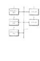
一般に、図5に示すように、スキャナ1やプリンタ2、あるいはスキャン機能、プリント機能を備えたファクシミリ装置とクライアントPC3、4、……、をLAN6で接続し、クライアントPCからプリントデータを送り、PCプリントし、あるいはスキャナ1でスキャンしたデータを読み出す画像処理システムが知られている(例えば、特許文献1参照)。
【0003】
【特許文献1】
特開2002−278736号公報
【0004】
【発明が解決しようとする課題】
カラープリンタと、カラースキャナ機能を持つプリンタベースのMFPを接続したい場合がある。この場合、高速のインターフェースが必要である。上記接続を行う時、USBのようにホストインターフェースとファクションモードを持つ場合には、スキャナとプリンタの接続、及びPC−スキャナ又はPC−プリンタを接続するのに、プリンタにはPC及びスキャナとの接続用に個別のインターフェースを持たせる必要がある。そのため、システム構成のための接続が複雑になるという問題がある。
【0005】
この発明は上記問題点に着目してなされたものであって、接続が簡単で容易にシステムを構成し得る画像処理システムを提供することを目的としている。
【0006】
【課題を解決するための手段】
この発明の請求項1に係る画像処理システムは、原稿を読み取るスキャナと、画像データをプリントするプリンタと、パーソナルコンピュータとからなる画像処理システムであって、前記パーソナルコンピュータと前記スキャナ間は、パーソナルコンピュータをホスト側、前記スキャナ側をデバイス側として接続し、前記スキャナと前記プリンタ間は、スキャナ側をホスト側とし、前記プリンタ側をデバイス側として接続する。
【0007】
この発明の画像処理システムでは、プリンタをスキャナ、PCに接続するのに、プリンタ側は1つのインターフェースで接続するようにしている。
【0008】
この発明の請求項4に係る画像処理システムは、原稿画像を読み取り、読取画像データを出力するスキャナ装置と、受信した画像データを記録媒体上に記録するプリンタ装置と、外部装置とを備える画像処理システムであって、一方の装置をホスト側、他方の装置をデバイス側とし、一方の装置のホスト機能と他方の装置のデバイス機能との協働によりデータ送受信を行うインターフェースで各装置間を接続し、外部装置とスキャナ装置との間は、外部装置をホスト側、スキャナ装置をデバイス側として接続し、スキャナ装置とプリンタ装置との間は、スキャナ装置をホスト側、プリンタ装置をデバイス側として接続している。
【0009】
また、この発明の請求項5に係るスキャナ装置は、原稿画像を読み取り、読取画像データを出力するスキャナ装置であって、
一方の装置をホスト側、他方の装置をデバイス側(スレーブ側)とし、一方の装置のホスト機能と他方の装置のデバイス機能との協働によりデータ送受信を行うインターフェース用の入出力ポートを少なくとも2つ有し、1つの入出力ポートを介して、自身がデバイス側として、ホスト側である外部装置と接続可能であり、他の入出力ポートを介して、自身がホスト側として、デバイス側であるプリンタ装置と接続可能にしている。
【0010】
この発明のスキャナ装置において、自身のデバイス機能により外部装置から受信したデータをプリンタ装置に転送すべきか否かを判断する第1判断手段と、第1判断手段により転送すべきと判断した場合、自身のホスト機能によりプリンタ装置にデータ転送を行うように制御する制御手段とを備えることができる。
【0011】
またこの発明のスキャナ装置において、自身のデバイス機能により外部装置から受信したデータが画像読取指示(TWEINの場合)又は画像読出要求(ボックス方式の場合)であるか否かを判断する第2判断手段と、第2判断手段により画像読取指示又は画像読出要求であると判断した場合、自身のデバイス機能により外部装置に読取画像データを送信するように制御する制御手段とを備えることができる。
【0012】
また、この発明のスキャナ装置において、コピー開始指示の入力を検出する検出手段と、コピー開始指示の入力に応じて、原稿の読み取りを行うとともに、それによって得た読取画像データを、自身のホスト機能によりプリンタ装置に送信するよう制御する制御手段とを備えることができる。
【0013】
また、この発明スキャナ装置において、コピー処理を実行する場合に、読取画像データのデータ形式を外部装置からプリンタ装置に転送すべきデータ(プリントデータ)として受信するデータ形式と同じ形式(例えば、Postseript)に変換する変換手段を備え、制御手段は、読取画像データをプリンタ装置に送信する際、変換手段による変換後のデータ形式で送信するように制御することができる。
【0014】
また、この発明のスキャナ装置において、自身のホスト機能によりプリンタ装置のステータス情報を読み出す読出手段と、読出手段により読み出したステータス情報を記憶する記憶手段と、自身のデバイス機能により外部装置から受信したデータがステータス情報要求であるか否かを判断する第3判断手段と、第3判断手段によりステータス情報要求であると判断した場合、記憶手段に記憶てしいるステータス情報を、自身のデバイス機能により外部装置に送信するように制御する制御手段とを備えることができる。
【0015】
【発明の実施の形態】
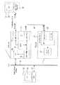
以下、実施の形態により、この発明をさらに詳細に説明する。図1は、この発明の一実施形態である画像処理システムの構成を示すブロック図である。この実施形態画像処理システムは、スキャナ11と、プリンタ21と、PC31とから構成されている。
【0016】
スキャナ11は、デバイス側のインターフェースであるUSB(デバイス)12と、ホスト側のインターフェースUSB(ホスト)13と、処理制御用のMPU14と、原稿画像を読み取るためのスキャナ機能部15と、NIC(Net work Interface Card)16とを備えている。この他、図示は省略しているが、スキャナ11には、操作部、表示部等を備えている。プリンタ21は、プリンタエンジン22の他、パラレルボード仕様IEEE1284採用のプリンタコントローラ23、デバイス側のインターフェースであるUSB(デバイス)24を備えている。
【0017】
スキャナ11は、USB(デバイス)12より、PC31のホスト側インターフェースであるUSB(ホスト)33に接続されている。また、スキャナ11のUSB(ホスト)13は、プリンタ21のUSB(デバイス)24に接続されている。スキャナ11は、更にNIC16より、LAN41を介して、PC51のNIC52に接続される。
【0018】
この実施形態画像処理システムにおいて、スキャナ11で、スキャン処理を行う場合について、図2のフロー図を参照して説明する。図2では、スキャン処理につき、TWAIN方式に対応する処理を示している。TWAIN方式とは、PCからの読み取り開始指示に基づいてスキャンを実行し、スキャンデータをPCに送信する方式である。 PC31から、USB(ホスト)32、USB(デバイス)12を経て、データを受信すると、ステップST1において、受信データがプリントデータか否か判定する。プリントデータの場合は、ステップST2へ移行する。一方、プリントデータでない場合は、ステップST3へ移行する。ステップST2においては、プリントデータをUSB(ホスト)13、USB(デバイス)24を経て、プリンタ21に転送する。ステップST3においては、受信したデータが読み取り開始指示を含むものであるか否かを判定する。読み取り開始指示の場合には、ステップST4へ移行する。一方、読み取り開始指示でない場合は、ステップST5へ移行する。
【0019】
ステップST4においては、スキャンを実行する。そして、スキャンデータをUSB(デバイス)12、USB(ホスト)32を経て、PC31に送信する。ステップST5においては、受信データがステータス情報の読出要求か否か判定する。ステータス情報の読出要求の場合は、ステップST6へ移行する。一方、読出要求でない場合は、ステップST7へ移行する。ステップST6においては、ステータス情報を読み出して、USB(デバイス)12、USB(ホスト)32を経て、PC31に送信する。ステップST7においては、他の処理を実行する。
【0020】
スキャナ11で、ボックス方式に対応するスキャン処理を行う場合を図3に示すフロー図を参照して説明する。ボックス方式は、スキャンして得たデータをスキャナ内に蓄積しておき、PCからスキャンデータの読出要求をスキャナに送ることにより、スキャナ内に蓄積していたスキャンデータを取り出せる方式である。ユーザは、スキャナ11内に原稿をセットした後、スキャナ11の操作部を介して読み取り開始指示を行うことにより、スキャンを実行し、スキャンデータをボックス(メモリ)に蓄積しておく。図3は、予めスキャンデータをスキャナ11内に蓄積した状態での処理を示すものである。
【0021】
この場合も、データを受信すると、ステップST11において、受信データがプリントデータか否か判定する。プリントデータの場合は、ステップST12へ移行する。一方、プリントデータでない場合は、ステップST13へ移行する。ステップST12においては、図2のステップST2と同様に、プリントデータをUSB(ホスト)13、USB(デバイス)24を経て、プリンタ21に転送する。ステップST3においては、受信したデータがスキャンデータの読出要求か否かを判定する。スキャンデータの読出要求の場合には、ステップST14へ移行する。一方、スキャンデータの読出要求でない場合は、ステップST15へ移行する。
【0022】
ステップST14においては、蓄積してあるスキャンデータを読み出す。そして、スキャンデータをUSB(デバイス)12、USB(ホスト)32を経て、PC31に送信する。ステップST15以降の処理は、図2のステップST5以降の処理と同様である。
【0023】
また、スキャナ11において、プリンタ21のUSB(デバイス)24を経て、USB(ホスト)13からデータを受信すると、図4に示すフロー図のステップST21において、受信データがステータス情報か否か判定する。プリンタ21より、紙無し、エラー発生などのステータス情報を受信した場合は、ステップST22へ移行する。一方、ステータス情報でない場合は、ステップST23へ移行する。ステップST22においては、紙無し、エラー発生などのステータス情報を、一旦メモリに格納する。ステップST23において、受信内容に応じた他の処理を実行する。
【0024】
次に、スキャナ11において、スキャン処理を実行する場合の処理を図5に示すフロー図を参照して説明する。この処理ルーチンに入ると、ステップST31においては、スキャンを実行する。そして、ステップST32へ移行する。ステップST32においては、コピー指示有りか否か判定する。操作部でコピーキーが操作されたなどにより、コピー指示有りの場合は、ステップST33へ移行する。一方、コピー指示なしの場合には、ステップST35へ移行する。
【0025】
ステップST33においては、読み取ったデータをPCから通常のプリンタに送られる形式にエミュレーションする。例えば、Postscript形式とする。そして、ステップST34へ移行する。ステップST34においては、エミュレーションしたデータをUSB(ホスト)13、USB(デバイス)24を経て、プリンタコントローラ23へ転送する。この転送を受けたプリンタ21では、プリンタエンジン22でプリントし、コピーを完了する。
【0026】
ステップST35においては、PC31からのスキャン指令有りか否か判定する。PCスキャン指令による場合には、ステップST36へ移行する。一方、PCスキャン指令でない場合には、ステップST37へ移行する。ステップST36においては、スキャンデータを所定のボックスに格納する。ステップST37においては、他の処理を実行する。
【0027】
この実施形態では、スキャナからスキャンデータを出力する際にデータをエミュレーションしているので、PCのドライバソフトとプリンタのコントローラは変更することなく、スキャナの追加だけでコピーシステムを実現できる。
【0028】
なお、上記実施形態において、USB12とUSB32、USB13とUSB24は、一方の装置のホスト機能と、他方の装置のデバイス機能(スレーブ機能)との共働によりデータ送受信を行うインターフェースの一例である。
【0029】
【発明の効果】
この発明によれば、パーソナルコンピュータと前記スキャナ間は、パーソナルコンピュータをホスト側、前記スキャナ側をデバイス側として接続し、前記スキャナと前記プリンタ間は、スキャナ側をホスト側とし、前記プリンタ側をデバイス側として接続するので、プリンタのインターフェースを1個とでき、接続が簡単で容易にシステムを構成することができる。
【0030】
プリンタ装置は、スキャナ装置からコピー用データを受信する場合も、PCプリント用データを受信する場合も、同じデータ形式でデータう受信できるため、既存のプリンタコントローラを有するプリンタ装置を使用でき、画像処理システムの構築が簡単に行える。
【図面の簡単な説明】
【図1】この発明の一実施形態である画像処理システムの構成を示すブロック図である。
【図2】同画像処理システムのスキャナにおけるPCプリントを行う場合の処理を説明するフロー図である。
【図3】同画像処理システムのスキャナにおけるPCデータ受信時の他の処理例を説明するフロー図である。
【図4】同スキャナにおけるプリンタからデータ受信時の処理を説明するフロー図である。
【図5】同スキャナにおけるスキャン時の処理を説明するフロー図である。
【図6】従来の画像処理システムの概略構成を示すブロック図である。
【符号の説明】
11 スキャナ
12 USB(デバイス)
13 USB(ホスト)
14 MPU
15 スキャナ機構部
16 NIC
21 プリンタ
22 プリンタエンジン
23 プリンタコントローラ
24 USB(デバイス)
31 PC
32 USB(ホスト)
33 PC本体[0001]
TECHNICAL FIELD OF THE INVENTION
The present invention relates to an image processing system including a scanner, a printer, and a personal computer (PC).
[0002]
[Prior art]
In general, as shown in FIG. 5, a
[0003]
[Patent Document 1]
JP 2002-278736 A
[Problems to be solved by the invention]
In some cases, it is desired to connect a color printer and a printer-based MFP having a color scanner function. In this case, a high-speed interface is required. When the above connection is made, if the host interface and the function mode are used like USB, the connection between the scanner and the printer, and the connection between the PC-scanner or the PC-printer, the printer must be connected to the PC and the scanner. You need to have a separate interface for the connection. Therefore, there is a problem that connection for the system configuration becomes complicated.
[0005]
SUMMARY OF THE INVENTION The present invention has been made in view of the above problems, and has as its object to provide an image processing system that can be easily connected and can easily configure a system.
[0006]
[Means for Solving the Problems]
An image processing system according to
[0007]
In the image processing system of the present invention, the printer is connected to the scanner and the PC by one interface.
[0008]
An image processing system according to a fourth aspect of the present invention includes: a scanner device that reads a document image and outputs read image data; a printer device that records received image data on a recording medium; and an external device. A system in which one device is a host and the other device is a device, and each device is connected by an interface that transmits and receives data in cooperation with a host function of one device and a device function of the other device. Between the external device and the scanner device, the external device is connected on the host side and the scanner device is connected on the device side. Between the scanner device and the printer device, the scanner device is connected on the host side and the printer device is connected on the device side. ing.
[0009]
A scanner device according to a fifth aspect of the present invention is a scanner device that reads a document image and outputs read image data,
One device is a host side and the other device is a device side (slave side), and at least two input / output ports for an interface for transmitting and receiving data in cooperation with a host function of one device and a device function of the other device. It is connectable to an external device which is a host through one input / output port as a device, and is a device as a host through another input / output port. It can be connected to a printer device.
[0010]
In the scanner device of the present invention, first determining means for determining whether or not data received from an external device should be transferred to the printer device by its own device function; And control means for controlling data transfer to the printer by the host function of the printer.
[0011]
Further, in the scanner device of the present invention, the second determining means for determining whether or not the data received from the external device by its own device function is an image reading instruction (in the case of TWEIN) or an image reading request (in the case of the box system). And a control unit for controlling the transmission of the read image data to the external device by its own device function when it is determined by the second determination unit that the instruction is an image reading instruction or an image reading request.
[0012]
Further, in the scanner device of the present invention, the detecting means for detecting the input of the copy start instruction, the original is read in response to the input of the copy start instruction, and the read image data obtained thereby is read by its own host function. And control means for controlling transmission to the printer device.
[0013]
Further, in the scanner device of the present invention, when executing a copy process, the data format of the read image data is the same as the data format (for example, Postscript) received as data (print data) to be transferred from the external device to the printer device. The control means can control the read image data to be transmitted in the data format converted by the conversion means when transmitting the read image data to the printer device.
[0014]
Further, in the scanner device of the present invention, reading means for reading status information of the printer device by its own host function, storage means for storing the status information read by the reading means, and data received from an external device by its own device function. Is a status information request, and if the third determination means determines that the request is a status information request, the status information stored in the storage means is externally transmitted by its own device function. Control means for controlling transmission to the device.
[0015]
BEST MODE FOR CARRYING OUT THE INVENTION
Hereinafter, the present invention will be described in more detail with reference to embodiments. FIG. 1 is a block diagram showing a configuration of an image processing system according to an embodiment of the present invention. The image processing system according to this embodiment includes a
[0016]
The
[0017]
The
[0018]
In the image processing system according to the present embodiment, a case where the
[0019]
In step ST4, a scan is performed. Then, the scan data is transmitted to the
[0020]
A case where the
[0021]
Also in this case, when data is received, it is determined in step ST11 whether the received data is print data. If it is print data, the process proceeds to step ST12. On the other hand, if it is not print data, the process proceeds to step ST13. In step ST12, similarly to step ST2 in FIG. 2, the print data is transferred to the
[0022]
In step ST14, the stored scan data is read. Then, the scan data is transmitted to the
[0023]
When the
[0024]
Next, a process when the
[0025]
In step ST33, the read data is emulated into a format sent from the PC to a normal printer. For example, the Postscript format is used. Then, the process proceeds to step ST34. In step ST34, the emulated data is transferred to the
[0026]
In step ST35, it is determined whether there is a scan command from the
[0027]
In this embodiment, since the data is emulated when the scan data is output from the scanner, the copy system can be realized only by adding the scanner without changing the driver software of the PC and the controller of the printer.
[0028]
In the above embodiment, the
[0029]
【The invention's effect】
According to the present invention, the personal computer and the scanner are connected to each other by connecting the personal computer to the host and the scanner to the device. The scanner and the printer are connected to the scanner and the printer, respectively. Since the connection is made on the side, only one printer interface is required, and the connection is simple and the system can be easily configured.
[0030]
The printer device can receive data in the same data format when receiving copy data from the scanner device or when receiving PC print data. Therefore, a printer device having an existing printer controller can be used, and image processing can be performed. The system can be easily constructed.
[Brief description of the drawings]
FIG. 1 is a block diagram illustrating a configuration of an image processing system according to an embodiment of the present invention.
FIG. 2 is a flowchart illustrating a process when PC printing is performed by a scanner of the image processing system.
FIG. 3 is a flowchart illustrating another example of processing when the scanner of the image processing system receives PC data.
FIG. 4 is a flowchart illustrating a process when the scanner receives data from a printer.
FIG. 5 is a flowchart illustrating processing during scanning by the scanner.
FIG. 6 is a block diagram illustrating a schematic configuration of a conventional image processing system.
[Explanation of symbols]
11
13 USB (host)
14 MPU
15
21
31 PC
32 USB (host)
33 PC body
Claims (10)
Translated fromJapanese前記パーソナルコンピュータと前記スキャナ間は、パーソナルコンピュータをホスト側、前記スキャナ側をデバイス側として接続し、前記スキャナと前記プリンタ間は、スキャナ側をホスト側とし、前記プリンタ側をデバイス側として接続することを特徴とする画像処理システム。An image processing system comprising a scanner for reading an original, a printer for printing image data, and a personal computer,
Between the personal computer and the scanner, the personal computer is connected as a host and the scanner is connected as a device, and between the scanner and the printer, the scanner is connected as a host and the printer is connected as a device. An image processing system characterized by the following.
一方の装置をホスト側、他方の装置をデバイス側とし、一方の装置のホスト機能と他方の装置のデバイス機能との協働によりデータ送受信を行うインターフェースで各装置間を接続し、外部装置とスキャナ装置との間は、外部装置をホスト側、スキャナ装置をデバイス側として接続し、スキャナ装置とプリンタ装置との間は、スキャナ装置をホスト側、プリンタ装置をデバイス側として接続したことを特徴とする画像処理システム。An image processing system comprising: a scanner device that reads a document image and outputs read image data; a printer device that records received image data on a recording medium; and an external device.
One device is the host side, the other device is the device side, and each device is connected by an interface that transmits and receives data in cooperation with the host function of one device and the device function of the other device. An external device is connected to the apparatus as a host and a scanner is connected to a device. A scanner is connected to the printer as a host and a printer is connected to the device as a device. Image processing system.
一方の装置をホスト側、他方の装置をデバイス側とし、一方の装置のホスト機能と他方の装置のデバイス機能との協働によりデータ送受信を行うインターフェース用の入出力ポートを少なくとも2つ有し、1つの入出力ポートを介して、自身がデバイス側として、ホスト側である外部装置と接続可能であり、他の入出力ポートを介して、自身がホスト側として、デバイス側であるプリンタ装置と接続可能であることを特徴とするスキャナ装置。A scanner device that reads a document image and outputs read image data,
One device is a host side, the other device is a device side, and has at least two input / output ports for an interface for transmitting and receiving data in cooperation with a host function of one device and a device function of the other device, Through one input / output port, the device itself can be connected as a device to an external device as a host, and the other device can be connected as a host to a printer as a device through another input / output port. A scanner device characterized in that it is possible.
制御手段は、読取画像データをプリンタ装置に送信する際、変換手段による変換後のデータ形式で送信するように制御することを特徴とする請求項8記載のスキャナ装置。When performing a copy process, a conversion unit that converts the data format of the read image data into the same format as the data format received as data to be transferred from the external device to the printer device,
9. The scanner device according to claim 8, wherein the control unit controls the transmission of the read image data to the printer device so that the read image data is transmitted in a data format converted by the conversion unit.
Priority Applications (3)
| Application Number | Priority Date | Filing Date | Title |
|---|---|---|---|
| JP2003135319AJP2004343275A (en) | 2003-05-14 | 2003-05-14 | Image processing system and scanner |
| US10/772,074US20040227974A1 (en) | 2003-05-14 | 2004-02-04 | Image processing system, scanner device and image processing method |
| CNB2004100431973ACN100409210C (en) | 2003-05-14 | 2004-05-14 | Scanning device and image processing method |
Applications Claiming Priority (1)
| Application Number | Priority Date | Filing Date | Title |
|---|---|---|---|
| JP2003135319AJP2004343275A (en) | 2003-05-14 | 2003-05-14 | Image processing system and scanner |
Publications (1)
| Publication Number | Publication Date |
|---|---|
| JP2004343275Atrue JP2004343275A (en) | 2004-12-02 |
Family
ID=33410702
Family Applications (1)
| Application Number | Title | Priority Date | Filing Date |
|---|---|---|---|
| JP2003135319APendingJP2004343275A (en) | 2003-05-14 | 2003-05-14 | Image processing system and scanner |
Country Status (3)
| Country | Link |
|---|---|
| US (1) | US20040227974A1 (en) |
| JP (1) | JP2004343275A (en) |
| CN (1) | CN100409210C (en) |
Cited By (2)
| Publication number | Priority date | Publication date | Assignee | Title |
|---|---|---|---|---|
| JP2006018734A (en)* | 2004-07-05 | 2006-01-19 | Oki Data Corp | Image processing apparatus and image processing system |
| JP2008211761A (en)* | 2006-12-05 | 2008-09-11 | Ricoh Co Ltd | Image forming apparatus and connection notification method |
Families Citing this family (7)
| Publication number | Priority date | Publication date | Assignee | Title |
|---|---|---|---|---|
| CN100514315C (en)* | 2004-04-27 | 2009-07-15 | 日本冲信息株式会社 | Peripherals of computer |
| US8022816B2 (en)* | 2005-03-21 | 2011-09-20 | Vela Systems, Inc. | System and method for field management using radio frequency tags |
| JP4618021B2 (en)* | 2005-07-06 | 2011-01-26 | 富士ゼロックス株式会社 | Image reading apparatus, image forming apparatus, image processing system, storage area sharing method of image reading apparatus, and storage area sharing method of image processing system |
| WO2008064240A2 (en)* | 2006-11-22 | 2008-05-29 | Vela Systems, Inc. | A method and system for inspecting and managing information |
| CN101672634B (en)* | 2009-10-16 | 2012-10-17 | 中国电子科技集团公司第四十五研究所 | Construction method of C-scan peak image of ultrasonic scanning microscope |
| JP5763615B2 (en)* | 2012-12-28 | 2015-08-12 | 京セラドキュメントソリューションズ株式会社 | Image forming system and image forming apparatus and information processing apparatus constituting the same |
| JP6111782B2 (en)* | 2013-03-27 | 2017-04-12 | セイコーエプソン株式会社 | Printing device |
Family Cites Families (92)
| Publication number | Priority date | Publication date | Assignee | Title |
|---|---|---|---|---|
| US4254083A (en)* | 1979-07-23 | 1981-03-03 | Eastman Kodak Company | Structural configuration for transport of a liquid drop through an ingress aperture |
| US4258001A (en)* | 1978-12-27 | 1981-03-24 | Eastman Kodak Company | Element, structure and method for the analysis or transport of liquids |
| US4321397A (en)* | 1979-01-31 | 1982-03-23 | Millipore Corporation | 4-Aminoantipyrine dye for the analytic determination of hydrogen peroxide |
| IT1130252B (en)* | 1980-02-04 | 1986-06-11 | Elvi Spa | METHOD FOR THE ELIMINATION OF BILIRIBUNA INTERFERENCE IN THE DOSAGE OF HYDROGEN PEROXIDE THROUGH A MODIFIED TRINDER REACTION |
| US4394512A (en)* | 1980-02-05 | 1983-07-19 | Boehringer Mannheim Gmbh | 1-(Substituted phenyl) aminoantipyrin compounds |
| US5183741A (en)* | 1983-10-13 | 1993-02-02 | Fuji Photo Film Co., Ltd. | Integral multilayer element for glucose analysis |
| US5141868A (en)* | 1984-06-13 | 1992-08-25 | Internationale Octrooi Maatschappij "Octropa" Bv | Device for use in chemical test procedures |
| DE3422732A1 (en)* | 1984-06-19 | 1985-12-19 | Boehringer Mannheim Gmbh, 6800 Mannheim | NEW AMINOPYRAZOLINONES, THEIR PRODUCTION AND USE |
| DE3446637A1 (en)* | 1984-12-20 | 1986-07-03 | Boehringer Mannheim Gmbh, 6800 Mannheim | MEANS TO IMPROVE THE DETECTION H (DOWN ARROW) 2 (DOWN ARROW) 0 (DOWN ARROW) 2 (DOWN ARROW) - SUPPLYING OXIDASE REACTIONS AND ITS USE |
| US4935346A (en)* | 1986-08-13 | 1990-06-19 | Lifescan, Inc. | Minimum procedure system for the determination of analytes |
| US5308767A (en)* | 1986-10-31 | 1994-05-03 | Fuji Photo Film Co., Ltd. | Method for control or calibration in a chemical analytical determination |
| US4794926A (en)* | 1986-11-24 | 1989-01-03 | Invictus, Inc. | Lancet cartridge |
| US4774192A (en)* | 1987-01-28 | 1988-09-27 | Technimed Corporation | A dry reagent delivery system with membrane having porosity gradient |
| DK163194C (en)* | 1988-12-22 | 1992-06-22 | Radiometer As | METHOD OF PHOTOMETRIC IN VITRO DETERMINING A BLOOD GAS PARAMETER IN A BLOOD TEST |
| US5302513A (en)* | 1988-06-29 | 1994-04-12 | Kyowa Medex Co., Ltd. | Method for determination of components |
| FI81120C (en)* | 1988-09-26 | 1990-09-10 | Kone Oy | FOERFARANDE FOER BESTAEMNING AV GLUKOS UR BIOLOGISKA VAETSKA SAMT REAGENSBLANDNING FOER TILLAEMPNING AV FOERFARANDET. |
| US4953552A (en)* | 1989-04-21 | 1990-09-04 | Demarzo Arthur P | Blood glucose monitoring system |
| IT1231916B (en)* | 1989-05-29 | 1992-01-15 | Ampliscientifica S R L | WEARABLE ARTIFICIAL PANCREAS |
| US5306623A (en)* | 1989-08-28 | 1994-04-26 | Lifescan, Inc. | Visual blood glucose concentration test strip |
| US6090790A (en)* | 1989-12-14 | 2000-07-18 | Eriksson; Elof | Gene delivery by microneedle injection |
| DE3942357A1 (en)* | 1989-12-21 | 1991-06-27 | Boehringer Mannheim Gmbh | 3-AMINOPYRAZOLO-HETEROCYCLES, THEIR USES FOR THE DETERMINATION OF HYDROGEN PEROXIDE, HYDROGEN PEROXIDE-FORMING SYSTEMS, PEROXIDASE, PEROXIDATIALLY ACTIVE SUBSTANCES OR OF ELECTRONIC AROMATIC COMPOUNDS, CORRESPONDING PROCEDURES AND COMPOUNDS THEREOF |
| US5115805A (en)* | 1990-02-23 | 1992-05-26 | Cygnus Therapeutic Systems | Ultrasound-enhanced delivery of materials into and through the skin |
| US5116759A (en)* | 1990-06-27 | 1992-05-26 | Fiberchem Inc. | Reservoir chemical sensors |
| US5208163A (en)* | 1990-08-06 | 1993-05-04 | Miles Inc. | Self-metering fluid analysis device |
| US5196302A (en)* | 1990-08-29 | 1993-03-23 | The United States Of America As Represented By The Sectetary Of The Navy | Enzymatic assays using superabsorbent materials |
| DE4217733A1 (en)* | 1992-05-29 | 1993-12-02 | Boehringer Mannheim Gmbh | Test carrier for analyte determination and method for its production |
| US5278079A (en)* | 1992-09-02 | 1994-01-11 | Enzymatics, Inc. | Sealing device and method for inhibition of flow in capillary measuring devices |
| US5383512A (en)* | 1993-01-27 | 1995-01-24 | Midwest Research Institute | Method for fabricating a substrate having spaced apart microcapillaries thereon |
| US5582184A (en)* | 1993-10-13 | 1996-12-10 | Integ Incorporated | Interstitial fluid collection and constituent measurement |
| WO1995011621A1 (en)* | 1993-10-28 | 1995-05-04 | I-Stat Corporation | Fluid sample collection and introduction device |
| US5536249A (en)* | 1994-03-09 | 1996-07-16 | Visionary Medical Products, Inc. | Pen-type injector with a microprocessor and blood characteristic monitor |
| DE4415896A1 (en)* | 1994-05-05 | 1995-11-09 | Boehringer Mannheim Gmbh | Analysis system for monitoring the concentration of an analyte in the blood of a patient |
| US5591139A (en)* | 1994-06-06 | 1997-01-07 | The Regents Of The University Of California | IC-processed microneedles |
| US5771890A (en)* | 1994-06-24 | 1998-06-30 | Cygnus, Inc. | Device and method for sampling of substances using alternating polarity |
| CA2170560C (en)* | 1995-04-17 | 2005-10-25 | Joseph L. Moulton | Means of handling multiple sensors in a glucose monitoring instrument system |
| WO1996037155A1 (en)* | 1995-05-22 | 1996-11-28 | Silicon Microdevices, Inc. | Micromechanical device and method for enhancing delivery of compounds through the skin |
| US6041253A (en)* | 1995-12-18 | 2000-03-21 | Massachusetts Institute Of Technology | Effect of electric field and ultrasound for transdermal drug delivery |
| US5879367A (en)* | 1995-09-08 | 1999-03-09 | Integ, Inc. | Enhanced interstitial fluid collection |
| WO1997010745A1 (en)* | 1995-09-08 | 1997-03-27 | Integ, Inc. | Body fluid sampler |
| US5735273A (en)* | 1995-09-12 | 1998-04-07 | Cygnus, Inc. | Chemical signal-impermeable mask |
| US5658515A (en)* | 1995-09-25 | 1997-08-19 | Lee; Abraham P. | Polymer micromold and fabrication process |
| US5741211A (en)* | 1995-10-26 | 1998-04-21 | Medtronic, Inc. | System and method for continuous monitoring of diabetes-related blood constituents |
| US5705018A (en)* | 1995-12-13 | 1998-01-06 | Hartley; Frank T. | Micromachined peristaltic pump |
| EP0868144B1 (en)* | 1995-12-19 | 2005-01-26 | Abbott Laboratories | Device for the detection of analyte and administration of a therapeutic substance |
| US5989845A (en)* | 1996-04-05 | 1999-11-23 | Mercury Diagnostics, Inc. | Diagnostic compositions and devices utilizing same |
| EP1862116A3 (en)* | 1996-05-17 | 2009-02-25 | Roche Diagnostics Operations, Inc. | Disposable element for use in a body fluid sampling device |
| EP1579814A3 (en)* | 1996-05-17 | 2006-06-14 | Roche Diagnostics Operations, Inc. | Methods and apparatus for sampling and analyzing body fluid |
| US6230051B1 (en)* | 1996-06-18 | 2001-05-08 | Alza Corporation | Device for enhancing transdermal agent delivery or sampling |
| DK0921840T3 (en)* | 1996-07-03 | 2003-09-22 | Altea Therapeutics Corp | Multiple mechanical microperforation of skin or mucosa |
| AT404513B (en)* | 1996-07-12 | 1998-12-28 | Avl Verbrennungskraft Messtech | METHOD AND MEASURING ARRANGEMENT FOR THE OPTICAL DETERMINATION OF TOTAL HEMOGLOBIN CONCENTRATION |
| US5858194A (en)* | 1996-07-18 | 1999-01-12 | Beckman Instruments, Inc. | Capillary, interface and holder |
| JPH1033196A (en)* | 1996-07-23 | 1998-02-10 | Unitika Ltd | Test piece |
| US6146361A (en)* | 1996-09-26 | 2000-11-14 | Becton Dickinson And Company | Medication delivery pen having a 31 gauge needle |
| US5866281A (en)* | 1996-11-27 | 1999-02-02 | Wisconsin Alumni Research Foundation | Alignment method for multi-level deep x-ray lithography utilizing alignment holes and posts |
| DE19652784A1 (en)* | 1996-12-19 | 1998-06-25 | Dade Behring Marburg Gmbh | Device (cuvette) for holding and storing liquids and for carrying out optical measurements |
| US6056734A (en)* | 1997-02-07 | 2000-05-02 | Sarcos Lc | Method for automatic dosing of drugs |
| US5911737A (en)* | 1997-02-28 | 1999-06-15 | The Regents Of The University Of California | Microfabricated therapeutic actuators |
| US5928207A (en)* | 1997-06-30 | 1999-07-27 | The Regents Of The University Of California | Microneedle with isotropically etched tip, and method of fabricating such a device |
| US5893870A (en)* | 1997-07-21 | 1999-04-13 | Actilife L.L.C. | Device and method for restricting venous flow for improved blood sampling |
| WO1999017117A1 (en)* | 1997-09-30 | 1999-04-08 | Amira Medical | Analytical device with capillary reagent carrier |
| US6001239A (en)* | 1998-09-30 | 1999-12-14 | Mercury Diagnostics, Inc. | Membrane based electrochemical test device and related methods |
| CA2313458C (en)* | 1997-12-11 | 2007-04-17 | Alza Corporation | Device for enhancing transdermal agent flux |
| ATE302041T1 (en)* | 1997-12-11 | 2005-09-15 | Alza Corp | DEVICE FOR INCREASE THE TRANSDERMAL FLOW OF ACTIVE INGREDIENTS |
| US6030827A (en)* | 1998-01-23 | 2000-02-29 | I-Stat Corporation | Microfabricated aperture-based sensor |
| US6103033A (en)* | 1998-03-04 | 2000-08-15 | Therasense, Inc. | Process for producing an electrochemical biosensor |
| JP3109470B2 (en)* | 1998-03-11 | 2000-11-13 | 日本電気株式会社 | Stratum corneum puncture needle and stratum corneum puncture member |
| US6106751A (en)* | 1998-03-18 | 2000-08-22 | The Regents Of The University Of California | Method for fabricating needles via conformal deposition in two-piece molds |
| US6091975A (en)* | 1998-04-01 | 2000-07-18 | Alza Corporation | Minimally invasive detecting device |
| US6175752B1 (en)* | 1998-04-30 | 2001-01-16 | Therasense, Inc. | Analyte monitoring device and methods of use |
| US6272364B1 (en)* | 1998-05-13 | 2001-08-07 | Cygnus, Inc. | Method and device for predicting physiological values |
| CA2329411C (en)* | 1998-05-13 | 2004-01-27 | Cygnus, Inc. | Collection assemblies for transdermal sampling system |
| DE69910003T2 (en)* | 1998-05-13 | 2004-04-22 | Cygnus, Inc., Redwood City | MONITORING PHYSIOLOGICAL ANALYSIS |
| US6077660A (en)* | 1998-06-10 | 2000-06-20 | Abbott Laboratories | Diagnostic assay requiring a small sample of biological fluid |
| US6503231B1 (en)* | 1998-06-10 | 2003-01-07 | Georgia Tech Research Corporation | Microneedle device for transport of molecules across tissue |
| US6206641B1 (en)* | 1998-06-29 | 2001-03-27 | Samsung Electro-Mechanics Co., Ltd. | Micro fan |
| US6100107A (en)* | 1998-08-06 | 2000-08-08 | Industrial Technology Research Institute | Microchannel-element assembly and preparation method thereof |
| US6558320B1 (en)* | 2000-01-20 | 2003-05-06 | Medtronic Minimed, Inc. | Handheld personal data assistant (PDA) with a medical device and method of using the same |
| US6251260B1 (en)* | 1998-08-24 | 2001-06-26 | Therasense, Inc. | Potentiometric sensors for analytic determination |
| JP2000175699A (en)* | 1998-12-15 | 2000-06-27 | Fuji Photo Film Co Ltd | Integration type multilayer chemical analytical element and measuring |
| JP2000231458A (en)* | 1999-02-10 | 2000-08-22 | Seiko Epson Corp | Composite device apparatus, composite device system, composite device control method, and medium recording composite device control program |
| CN1218273C (en)* | 1999-04-02 | 2005-09-07 | 虹光精密工业股份有限公司 | scanning photocopying device |
| US6192891B1 (en)* | 1999-04-26 | 2001-02-27 | Becton Dickinson And Company | Integrated system including medication delivery pen, blood monitoring device, and lancer |
| CN2371600Y (en)* | 1999-05-04 | 2000-03-29 | 仇书鸾 | Printing scanning controller |
| US6256533B1 (en)* | 1999-06-09 | 2001-07-03 | The Procter & Gamble Company | Apparatus and method for using an intracutaneous microneedle array |
| US6251083B1 (en)* | 1999-09-07 | 2001-06-26 | Amira Medical | Interstitial fluid methods and devices for determination of an analyte in the body |
| US6577899B2 (en)* | 2000-01-21 | 2003-06-10 | Medtronic Minimed, Inc. | Microprocessor controlled ambulatory medical apparatus with hand held communication device |
| TW563327B (en)* | 2000-03-10 | 2003-11-21 | Avision Inc | Scanning device having output port connected with a printing device or a storage device |
| US6540675B2 (en)* | 2000-06-27 | 2003-04-01 | Rosedale Medical, Inc. | Analyte monitor |
| US6603987B2 (en)* | 2000-07-11 | 2003-08-05 | Bayer Corporation | Hollow microneedle patch |
| US7224484B1 (en)* | 2000-10-04 | 2007-05-29 | Reeves Gerald J | Scanner calibration with dead pixel compensation |
| TWI222001B (en)* | 2000-11-10 | 2004-10-11 | Sanyo Electric Co | Microcomputer |
| US6530892B1 (en)* | 2001-03-07 | 2003-03-11 | Helen V. Kelly | Automatic skin puncturing system |
- 2003
- 2003-05-14JPJP2003135319Apatent/JP2004343275A/enactivePending
- 2004
- 2004-02-04USUS10/772,074patent/US20040227974A1/ennot_activeAbandoned
- 2004-05-14CNCNB2004100431973Apatent/CN100409210C/ennot_activeExpired - Fee Related
Cited By (2)
| Publication number | Priority date | Publication date | Assignee | Title |
|---|---|---|---|---|
| JP2006018734A (en)* | 2004-07-05 | 2006-01-19 | Oki Data Corp | Image processing apparatus and image processing system |
| JP2008211761A (en)* | 2006-12-05 | 2008-09-11 | Ricoh Co Ltd | Image forming apparatus and connection notification method |
Also Published As
| Publication number | Publication date |
|---|---|
| US20040227974A1 (en) | 2004-11-18 |
| CN100409210C (en) | 2008-08-06 |
| CN1550999A (en) | 2004-12-01 |
Similar Documents
| Publication | Publication Date | Title |
|---|---|---|
| US7200685B2 (en) | Communication apparatus for communicating data between separate toplogies, and related method, storage medium, and program | |
| JP2003127472A (en) | Recording apparatus, control method thereof, and program | |
| JP2008030287A (en) | Printing apparatus, printing system and program | |
| JP3817494B2 (en) | Image processing apparatus and control method thereof | |
| JP2004343275A (en) | Image processing system and scanner | |
| US9894243B2 (en) | Non-transitory computer-readable medium storing instructions and image forming apparatus, to perform monitoring of status information | |
| KR20060056997A (en) | Image supply apparatus and recording apparatus, recording system including these apparatuses, and communication control method in the recording system | |
| JP5679644B2 (en) | Information processing apparatus, control method thereof, and program | |
| JP5338538B2 (en) | Image processing apparatus, control method thereof, and control program | |
| JPH09238209A (en) | Image input / output system, image reading apparatus and control method thereof | |
| JP2002314736A (en) | Scanner device and control method thereof | |
| JP2005184360A (en) | Usb-compatible composite copy machine, host computer, and usb-compatible copy machine control system | |
| JP5361248B2 (en) | Image forming apparatus, image forming method, storage medium, and program | |
| JP2019137068A (en) | Printing system, printing device, control method, and program | |
| JP3444282B2 (en) | Printer / scanner multifunction peripheral, control method therefor, and storage medium storing computer readable program | |
| JP5058023B2 (en) | Image processing apparatus, image processing system, and image processing method | |
| JP2007081893A (en) | Image input device and printing system | |
| JP2002032323A (en) | Communication aggregation device, control method therefor, and storage medium | |
| JP3544021B2 (en) | Image processing apparatus and method | |
| JP4047147B2 (en) | Recording apparatus and control method thereof | |
| JP2000156760A (en) | Image processing apparatus, image processing system, and storage medium | |
| JP2000032248A (en) | Data processing apparatus, control method thereof, and recording medium | |
| JPS6348046A (en) | Image reading device | |
| JP5056470B2 (en) | Printer controller for multifunction devices | |
| JP3571787B2 (en) | Image processing apparatus and control method thereof |
Legal Events
| Date | Code | Title | Description |
|---|---|---|---|
| A977 | Report on retrieval | Free format text:JAPANESE INTERMEDIATE CODE: A971007 Effective date:20051110 | |
| A131 | Notification of reasons for refusal | Free format text:JAPANESE INTERMEDIATE CODE: A131 Effective date:20051115 | |
| A521 | Written amendment | Free format text:JAPANESE INTERMEDIATE CODE: A523 Effective date:20060111 | |
| A02 | Decision of refusal | Free format text:JAPANESE INTERMEDIATE CODE: A02 Effective date:20060207 |