JP2004339575A - Method of manufacturing rolling device parts - Google Patents
Method of manufacturing rolling device partsDownload PDFInfo
- Publication number
- JP2004339575A JP2004339575AJP2003138272AJP2003138272AJP2004339575AJP 2004339575 AJP2004339575 AJP 2004339575AJP 2003138272 AJP2003138272 AJP 2003138272AJP 2003138272 AJP2003138272 AJP 2003138272AJP 2004339575 AJP2004339575 AJP 2004339575A
- Authority
- JP
- Japan
- Prior art keywords
- tempering
- bearing
- component material
- rolling
- peening
- Prior art date
- Legal status (The legal status is an assumption and is not a legal conclusion. Google has not performed a legal analysis and makes no representation as to the accuracy of the status listed.)
- Pending
Links
Images


Classifications
- F—MECHANICAL ENGINEERING; LIGHTING; HEATING; WEAPONS; BLASTING
- F16—ENGINEERING ELEMENTS AND UNITS; GENERAL MEASURES FOR PRODUCING AND MAINTAINING EFFECTIVE FUNCTIONING OF MACHINES OR INSTALLATIONS; THERMAL INSULATION IN GENERAL
- F16C—SHAFTS; FLEXIBLE SHAFTS; ELEMENTS OR CRANKSHAFT MECHANISMS; ROTARY BODIES OTHER THAN GEARING ELEMENTS; BEARINGS
- F16C33/00—Parts of bearings; Special methods for making bearings or parts thereof
- F16C33/30—Parts of ball or roller bearings
- F16C33/58—Raceways; Race rings
- F16C33/64—Special methods of manufacture
- F—MECHANICAL ENGINEERING; LIGHTING; HEATING; WEAPONS; BLASTING
- F16—ENGINEERING ELEMENTS AND UNITS; GENERAL MEASURES FOR PRODUCING AND MAINTAINING EFFECTIVE FUNCTIONING OF MACHINES OR INSTALLATIONS; THERMAL INSULATION IN GENERAL
- F16C—SHAFTS; FLEXIBLE SHAFTS; ELEMENTS OR CRANKSHAFT MECHANISMS; ROTARY BODIES OTHER THAN GEARING ELEMENTS; BEARINGS
- F16C33/00—Parts of bearings; Special methods for making bearings or parts thereof
- F16C33/30—Parts of ball or roller bearings
- F16C33/58—Raceways; Race rings
- F16C33/583—Details of specific parts of races
- F16C33/585—Details of specific parts of races of raceways, e.g. ribs to guide the rollers
Landscapes
- Engineering & Computer Science (AREA)
- General Engineering & Computer Science (AREA)
- Mechanical Engineering (AREA)
- Manufacturing & Machinery (AREA)
- Heat Treatment Of Articles (AREA)
Abstract
Translated fromJapaneseDescription
Translated fromJapanese【0001】
【発明の属する技術分野】
本発明は、転がり軸受、ボールねじ、リニアガイド等の転動装置の部品を製造する方法に関する。
【0002】
【従来の技術】
自動車、農業機械、建設機械、鉄鋼機械などのトランスミッションやエンジン等で使用される玉軸受等の転がり軸受は、図12に示されるように、内周面に転動体軌道溝1aを有する外側軌道輪1と、この外側軌道輪1の転動体軌道溝1aと対向する転動体軌道溝2aを外周面に有する内側軌道輪2と、これら軌道輪1,2の転動体軌道溝1a,2a間に転動自在に配設された複数の転動体3とからなり、このような転がり軸受を例えば自動車のトランスミッション用軸受のように潤滑油中で使用する場合には、潤滑油中に摩耗粉等の異物が混入している場合でも軌道輪の表面、特に軌道溝表面に剥離(フレーキング)が早期に生じないようにする必要がある。
【0003】
摩耗粉等の異物が混入していない清浄な潤滑油中で転がり軸受を使用した場合の軸受寿命は、通常、軌道溝表面の剪断応力位置からの内部起点による剥離に支配される。しかし、潤滑油中に異物が混入している場合には、軌道溝表面の圧痕を起点とした剥離や軌道溝表面の表面摩耗などに支配され、清浄な潤滑油中で使用した場合に比べ、軌道輪の疲労寿命が大きく低下する。従って、潤滑油中に異物が混入している場合の軸受寿命を延ばすためには、軌道溝表面の耐圧痕性や耐摩耗性に優れた軌道輪を得る必要がある。
【0004】
上記のような異物混入潤滑下で使用される転がり軸受の軌道輪に関しては、靭性が高く且つ異物による圧痕や摩耗が生じ難いことが要求される。しかし、靭性を高くすることと硬さを高くすることは一般的には相反することであり、両方の性能が優れている軌道輪等の軸受部品を得ることは非常に困難である。そこで、靭性が高く且つ表面の耐圧痕性や耐摩耗性に優れた軌道輪等の軸受部品を得る方法として、高炭素クロム軸受鋼からなる軸受部品素材に焼入れを施し、次いで軸受部品素材の所望部分にショットピーニングを施して残留応力を付与し、残留オーステナイトをマルテンサイトに変態させて硬さを高めた後、軸受部品素材に焼戻しを施す方法が特許文献1に開示されている。
【0005】
自動車、農業機械、建設機械、鉄鋼機械などのトランスミッションやエンジン等に使用される転がり軸受の軸受材料としては、軸受鋼2種(SUJ2)等の各種の合金鋼が知られている。前記のような転がり軸受は、近年の機械の性能向上に伴う荷重の増大や軸受のサイズダウンにより軸受の負荷面圧が増大する傾向にあり、耐久寿命の改善が要求されている。また、転がり軸受は高面圧下で繰り返し剪断応力を受けるため、その剪断力に耐えられる転がり疲労寿命を確保する必要がある。転がり軸受の寿命を延ばすためには、転動体の表面硬さを所望の値にすると同時に、転動体の表面硬さと軌道輪の表面硬さに高低関係を付与することが重要である。何故なら、転がり軸受の使用条件が例えば高面圧であったり、油膜形成が不十分であったり、ラジアル荷重及びスラスト荷重の両方が作用したり、あるいは異物混入潤滑である場合には、軌道輪よりも先に転動体の表面にフレーキングが発生してしまうことからである。しかし、転動体の表面硬さが軌道輪の表面硬さより低い場合や両者の表面硬さが同等である場合には、早期剥離が転動体に集中的に生じ、軸受寿命を大きく低下させる。
【0006】
そこで、軸受材料として高炭素クロム軸受鋼を用い、これを焼入れして焼戻す際に転動体の焼戻温度を140℃〜145℃、軌道輪の焼戻温度を160℃〜180℃に設定して焼戻すことで、転動体の表面硬さを軌道輪の表面硬さに比べてHRCで1〜2程度高くし、転動体の表面硬さと軌道輪の表面硬さに高低関係を付与することで転がり軸受の寿命を向上させる従来例が知られている。
【0007】
しかし、前述した従来例は、転動体の焼戻温度を軌道輪の焼戻温度より20〜40℃程度低い温度に抑えて焼戻しを行うことで、転がり軸受の長寿命化に必要な転動体と軌道輪との表面硬さの差を得ているため、転動体の表面硬さが向上する反面、焼戻し過程で付与すべき衝撃強度や繰り返し荷重に対する強度等に必要な粘靭性の向上が十分に行われない。このため、潤滑油中に存在する異物によって引き起こされる損傷箇所からクラックが発生し、それが起点となって早期フレーキングが生じ、転がり軸受の寿命を大きく低下させるなどの問題がある。また、転動体の焼戻温度を140℃〜145℃に抑えて焼戻しを行うと、転がり軸受を準高温または高温の条件で使用した際に残留オーステナイトがマルテンサイトに変態し、その結果、寸法変化や内部歪み等が生じ易くなり、軸受の寸法安定性を低下させるという問題がある。
【0008】
このような問題を解決するために、高炭素クロム鋼、浸炭鋼、高温軸受用高速鋼、マルテンサイト系ステンレス鋼等からなる転動体素材の焼戻しを180℃〜220℃の温度で行って転動体を製造する方法が特許文献2に開示されている。また、特許文献3及び4には、軸受として必要な靭性を確保するために、残留オーステナイトを残しつつショットピーニングにより硬さを硬くして残留応力を発生される軸受部品の製造方法が記載されている。
【0009】
【特許文献1】
特開平5−195069号公報
【特許文献2】
特開平9−170624号公報
【特許文献3】
特開平5−195070号公報
【特許文献4】
特開平5−163526号公報
【0010】
【発明が解決しようとする課題】
特許文献1に開示された軸受部品の製造方法は、焼入れ後の軸受部品素材にショットピーニングを施してから焼戻しを施す方法であるため、ショットピーニング時に割れ等が軸受部品素材に発生したり、靭性が不足したりするなどの問題があった。また、特許文献1には軸受部品素材にショットピーニングを施す前に焼戻しを行う方法も開示されているが、この場合には十分に硬さが向上しないという問題があった。
【0011】
特許文献2に開示された方法は、より厳しい条件下で使用される場合の耐久性が十分でないという問題があった。
特許文献3に開示された方法では、ショットピーニング処理時に割れが発生したり、靭性が足りずに使用時に破損したりする虞がある。
また、特許文献4に開示された方法も上記と同様の問題が起こる可能性があり、さらに条件を整えないと所望の硬さを十分に得られない場合があった。
【0012】
本発明は、このような問題点に鑑みてなされたものであり、靭性が高く、しかも表面の耐圧痕性及び耐摩耗性に優れ、高面圧で異物が混入した潤滑油中での軸受寿命を向上させることが可能な転動装置部品を得ることのできる転動装置部品の製造方法を提供することを目的とする。また、本発明は靭性が高く、しかも表面の耐圧痕性及び耐摩耗性に優れ、高面圧で異物が混入した潤滑油中での軸受寿命を向上させることのできる転動装置を提供することを目的とする。
【0013】
【課題を解決するための手段】
上記の目的を達成するために、請求項1の発明に係る転動装置部品の製造方法は、高炭素クロム軸受鋼からなる転動装置用部品素材に焼入れを施して前記部品素材を硬化処理する焼入れ工程と、この焼入れ工程の後に前記部品素材に焼戻しを施す第一次焼戻し工程と、この第一次焼戻し工程の後に前記部品素材の所望部分に機械的表面硬化処理を施す機械的表面硬化処理工程と、この機械的表面硬化処理工程の後に前記部品素材に焼戻しを施す第二次焼戻し工程とを含むことを特徴とする。
【0014】
請求項2の発明は、請求項1記載の転動装置部品の製造方法において、前記部品素材が前記第一次焼戻し工程において80℃〜130℃の焼戻温度で焼戻されることを特徴とする。
請求項3の発明は、請求項1または2記載の転動装置部品の製造方法において、前記部品素材が前記第二次焼戻し工程において180℃〜220℃の焼戻温度で焼戻されることを特徴とする。
【0015】
請求項4の発明は、請求項1乃至3のいずれかに記載の転動装置部品の製造方法において、前記機械的表面硬化処理工程が前記部品素材をショットピーニング加工する工程を含むことを特徴とする。
請求項5の発明は、請求項1乃至3のいずれかに記載の転動装置部品の製造方法において、前記機械的表面硬化処理工程が前記転動装置の転動体素材にバレルピーニング処理を施す工程であることを特徴とする。
【0016】
請求項6の発明は、請求項5記載の転動装置部品の製造方法において、前記転動体素材にバレルピーニング処理を施す工程が、前記転動装置の転動体径の150〜250%の直径を有する多数の鋼球で前記転動体素材をバレルピーニング処理する工程を含むことを特徴とする。
請求項7の発明は、請求項4記載の転動装置部品の製造方法において、前記ショットピーニング加工により前記部品素材の残留オーステナイトをショットピーニング加工前の80%以下に低下させると共に硬さをショットピーニング加工前よりHv50以上に向上させることを特徴とする。
【0017】
請求項8の発明に係る転動装置部品の製造方法は、鋼からなる転動装置部品素材に浸炭または浸炭窒化処理を施した後、前記転動装置部品素材に焼入れを施す焼入れ工程と、この焼入れ工程の後に前記部品素材に焼戻しを施す第一次焼戻し工程と、この第一次焼戻し工程の後に前記部品素材を機械的に表面硬化処理する機械的表面硬化処理工程と、この機械的表面硬化処理工程の後に前記部品素材に焼戻しを施す第二次焼戻し工程とを含むことを特徴とする。
【0018】
請求項9の発明は、請求項8記載の転動装置部品の製造方法において、前記機械的表面硬化処理工程は、前記転動装置の部品素材をバレルピーニング処理するバレルピーニング処理工程を含むことを特徴とする。
請求項10の発明は、請求項8または9記載の転動装置部品の製造方法において、前記部品素材の残留オーステナイト量を3〜30vol%とし、かつ前記部品素材の最大圧縮応力を−500〜−1300MPaとしたことを特徴とする。
【0019】
請求項11の発明は、請求項9記載の転動装置部品の製造方法において、前記部品素材の残留オーステナイト量を、前記バレルピーニング処理工程前の残留オーステナイト量に対して40〜80%としたことを特徴とする。
請求項12の発明は、請求項8乃至11のいずれか1項記載の転動装置部品の製造方法において、前記部品素材の表面硬さをHv800以上としたことを特徴とする。
【0020】
請求項13の発明に係る転動装置は、請求項1乃至12のいずれか1項記載の製造方法によって製造された転動装置部品を備えて構成されることを特徴とする。
本発明者らは、ショットピーニング処理の作用及び効果について詳細に研究を行った結果、転がり疲労寿命の向上に最も効果がある方法を見出した。
【0021】
ショットピーニング工程によって軸受部品素材の表層部に存在する残留オーステナイトをマルテンサイトに加工誘起変態させて軸受部品素材の表面硬さを向上させる。このとき得られるマルテンサイト組織は、熱処理時すなわち焼入れ時に得られるマルテンサイト組織に比べ非常に微細であるばかりでなく、高密度の転位が導入される。このような組織は非常に硬いだけでなく、疲労強度や転がり疲れ寿命にとって非常に有用な組織である。そして、異物による圧痕や摩耗が生じ難い。しかも、ショットピーニング工程によって軸受部品素材の表層部に残留圧縮応力が付与されるため、軸受部品素材の表面に圧痕が生じた場合でも圧痕を起点とする亀裂の進展を抑えられる。また、ショットピーニングによって軸受部品素材の表層部に存在する残留オーステナイトだけをマルテンサイトに変態させるため、軸受部品素材の表層部より内方の部分には残留オーステナイトが存在し、軸受として必要な靭性を確保できる。
【0022】
ショットピーニング工程の前後には、軸受部品素材の焼戻しを行う。ショットピーニング工程の前に焼戻しを行う理由は、焼入れによる靭性の減少を回復させるためであり、これにより軸受部品素材に割れ等がショットピーニング時に発生することを防ぐことができる。ただし、ショットピーニング加工時の割れ等を防ぐための焼戻しなので、仕上げ前の焼戻温度より低い温度で焼戻しを行う。
【0023】
ショットピーニング工程の後に焼戻しを行う理由は、ショットピーニングで低下した軸受部品素材の靭性を向上させ、残留応力のむらを除くためである。この焼戻しにより軸受部品素材の組織が均一となり、転がり軸受の寿命を向上させることができる。ショットピーニング工程において軸受部品素材の表層部に付与された残留圧縮応力が、その後の焼戻し工程により一部緩和されて安定する。このため、ショットピーニング工程において付与する残留圧縮応力は、最終的な目標値より少し高くしておくことが望ましい。また、ショットピーニング加工によって硬化処理された表層部の硬さも、その後の焼戻し工程によって少し低下するので、ショットピーニング工程において硬さを最終的な目標値より少し高くしておくことが望ましい。
【0024】
軸受部品の表層部に存在する残留オーステナイトが20体積%を越えると、十分な表面硬さや残留圧縮応力を得られなくなる。従って、軸受部品素材をショットピーニングする際には、軸受部品素材の表層部に存在する残留オーステナイトが実質的に20体積%以下となるように、ショットピーニングを行うことが望ましい。
【0025】
軸受部品表層部の最大残留圧縮応力が−500MPaを下回ると、軸受寿命を十分に延ばすことができなくなる。また、最大残留圧縮応力が−1300MPaを上回ると、ショットピーニングの際に軸受部品素材の消耗が激しく、処理時間も長くなり、コストアップにつながることがある。従って、軸受部品素材をショットピーニングする際には、素材表層部の最大残留圧縮応力が−500〜−1300MPaとなるように、ショットピーニングを行うことが望ましい。
【0026】
軸受部品の表面硬さがHv800を下回ると、異物による圧痕が発生しやすくなり、軸受の寿命向上を期待できなくなる。また、軸受部品の表面硬さがHv1000を上回ると、軸受部品の靭性が低下する。従って、軸受部品素材をショットピーニングする際には、軸受部品素材の表面硬さがHv800〜Hv1000となるように、ショットピーニングを行うことが望ましい。
【0027】
本発明者らは、バレルピーニングの作用、効果について詳細に研究を行なった結果、転がり疲れ寿命の向上に最も効果がある方法を見出した。すなわち、従来、バレルピーニングは焼入焼戻しの後に行なっていたが、これを焼入れ後に行なうことにより得られる効果が増大する。これはバレルピーニング処理は転動体の表層部に存在する残留オーステナイトを加工誘起変態によりマルテンサイト組織に変態させるが、そのとき得られるマルテンサイト組織は熱処理時すなわち焼入れ時に得られるマルテンサイト組織に比べ、非常に微細であるばかりでなく、高密度の転位が導入される。このような組織は、非常に硬いだけでなく、疲労強度、すなわち転がり疲れにとって非常に有用な組織である。このような加工誘起変態によるマルテンサイト組織が多いほど疲労強度に有利になってくる。そのためには、ショットピーニング処理前の残留オーステナイト量は多いほどよい。焼戻し前にショットピーニングを行なったものは、焼戻し後にショットピーニングを行なったものよりも加工硬化により生成されるマルテンサイト組織の割合が多く、疲労強度向上効果が得られる。
【0028】
転動体素材にバレル法ピーニングを施す際、製造しようとする転動体径の150〜250%の直径を有する多数の鋼球を研磨材として鋼製バレル容器内に入れてバレルピーニング処理を行うと、ピーニングの効果がより有効に作用する。すなわち、異なる径の鋼球がバレル容器内でぶつかり合うことで、ピーニングの効果が大きな径の鋼球側にはより表面側に、小さな径の鋼球側にはより内面側に現われる。また、大きな径の鋼球とぶつかり合うことで、より大きな残留応力を得ることができる。軸受の鋼球においては、より表面近傍の鋼のミクロ組織を微細で、高転位密度にすることにより長寿命効果を得ることができる。
【0029】
なお、焼入れ後にピーニングを行なうと、割れが発生する可能性が高い。そのため、焼入れ後に低温焼戻し、すなわち130℃以下で焼戻しを行なうことによりピーニング割れを防ぐことができる。この場合、低温焼戻しによる残留オーステナイトの変態はほとんど見られず、本発明の効果を十分に得ることが出来る。ここで従来の方法との違いについて詳述する。軸受用転動体表面を硬化する方法としては、特公平1−12813号公報に代表的な方法が開示されている。すなわち、この方法は焼入鋼からなる鋼球に対して焼入焼戻を行った後、バレル処理を行い、鋼球表面を硬化する方法である。
【0030】
また、本発明者らは、熱処理とショットピーニング処理の作用及び効果について詳細に研究を行った結果、転がり疲労寿命の向上に最も効果がある方法を見出した。特に、少なくとも軌道面に浸炭または浸炭窒化を施し、軌道面の炭素含有率と窒素含有率を上げることで、軌道面に炭素及び窒素の固溶強化作用と窒素の焼戻し軟化抵抗性を付与することができ、表面硬さを向上させることができる。このため、軌道輪をショットピーニング後に通常焼戻し温度(180〜220℃)で焼戻しても、軌道輪に必要な表面硬さと靭性の向上を付与することができる。
【0031】
また、浸炭窒化は、被浸炭窒化材に炭素と窒素が固溶するため、例えば、浸炭等に比べて、固溶強化作用の効果が大きい。さらに、窒素は焼戻し軟化抵抗性を有するものであり、被浸炭窒化材の表面をより硬くすることができる。また、例えば高温で軸受を焼戻しでき、常温での使用は勿論のこと、準高温〜高温(100〜200℃)下で前記軸受を使用しても、寸法安定性、長寿命化が損なわれることがない。
なお、浸炭窒化に際しては、表面硬化層の固溶窒化量が上記の範囲に収まるとともに、表面炭素固溶量が1.2〜1.6重量%となるように、炭素及び窒素を固溶させることが好ましい。
【0032】
ショットピーニング工程によって軸受部品素材の表層部の残留オーステナイトをマルテンサイトに加工誘起変態させて硬さを高める。このとき得られるマルテンサイト組織は、熱処理時、すなわち焼入れ時に得られるマルテンサイト組織に比べ、非常に微細であるばかりでなく、高密度の転移が導入されるのである。このような組織は非常に硬いだけでなく、疲労強度、転がり疲労にとって非常に有用な組織なのである。そして、異物による圧痕や摩耗が生じにくい。しかも、ショットピーニング工程によって表層部に残留圧縮応力を付与するので、圧痕が生じた場合でも、これを起点とする亀裂の進展が抑えられる。また、ショットピーニングによって表層部の残留オーステナイトだけをマルテンサイトに変態させるので、表層部より内側の部分には残留オーステナイトが存在し、軸受として必要な靭性が得られる。これらのことから、ショットピーニング時にはできるだけ多くの残留オーステナイトをマルテンサイトに変態させることが望ましい。
【0033】
充分な硬さと残留圧縮応力を得るために、本発明者らは鋭意研究を重ねた。その結果、ショットピーニングにより残留オーステナイトを加工前の80%以下に下げ、硬さを加工前よりHv50以上上げると、軸受性能が特に良くなることが分かった。ここで、残留オーステナイトを加工前の80%以下に下げる理由は、80%を越える場合、充分な硬さや残留圧縮応力の発生を得られないからある。また、過度の残留オーステナイトは使用時の変形の恐れがある。硬さを加工前よりHv50以上上げる理由は、充分な硬さを得るためである。硬さを上げないと、圧痕の発生を抑制することが難しい。
【0034】
ショットピーニング工程の前後には焼戻しを行う。焼入れ後、ショットピーニング前に焼戻しを行うのは、焼入れによる靭性の減少を回復させるためである。この焼戻しにより、ショットピーニング加工時の割れを防ぐことができる。ただし、ショットピーニング加工のための焼戻しなので、仕上げ前の焼戻しほど温度を上げずに行う。これは、焼戻しによる残留オーステナイトの減少を防ぐためである。SUJ2では80〜130℃が適当である。
【0035】
同様に、ショットピーニング後、仕上げ工程前に焼戻しを行う理由は、靭性を向上させ、残留応力のむらを除くためである。この焼戻しにより、仕上げた製品の組織が均一となり、長寿命になる。ショットピーニング工程において軸受部品表層部に付与された残留圧縮応力が、その後の焼戻し工程により一部緩和されて安定する。このため、ショットピーニング工程において付与する残留圧縮応力は、最終的な目標値より少し高くしておく。また、ショットピーニング工程において高められた表層部の硬さも、その後の焼戻し工程によって少し低下するので、ショットピーニング工程において硬さを最終的な目標値より少し高くしておく。
【0036】
なお、残留オーステナイトは実質的に3vol%以上30vol%以下が望ましい。3%に満たないと耐圧痕性に劣るからである。30vol%を越えると十分な表面硬さや残留圧縮応力が得られないからである。
最大残留圧縮応力を−500〜−1300MPaにする理由は、−500MPaを下回ると十分な軸受寿命向上が得られないためであり、また、−1300MPaを上回ると、ショットピーニング工程の際にショット粒の消耗が激しく、処理時間も長くなりコストアップとなるからである。また、高負荷が作用した場合、鋼にさらなる大きな圧縮が加わり、変形、破損を起こす可能性があるからである。
さらに、硬さをビッカース硬さでHv800〜1000の範囲内にする理由は、Hv800を下回ると、表層部での圧痕の発生抑止効果が十分でなく、軸受寿命の向上がみられないからであり、また、Hv1000を上回ると靭性が低下するためである。
【0037】
【発明の実施の形態】
以下、図面を参照して本発明の実施形態について説明する。
図1は本発明を軸受軌道輪の製造方法に適用した一実施形態を示す図であり、同図に示すように、本実施形態では、SUJ2等の高炭素クロム軸受鋼を鍛造および旋削加工して得られた軌道輪素材を820℃〜900℃の温度で焼入れした後(焼入れ工程S1)、軌道輪素材に対して80℃〜130℃の温度で焼戻しを行う(第一次焼戻し工程S2)。次に、軌道輪素材の表層部(転動体の直径をammとしたとき軌道輪素材の表面から0.05ammの深さを持つ層)に−500〜−1300MPaの残留圧縮応力が付与され且つ表層部の残留オーステナイトが実質的に20vol%以下となるように、軌道輪素材を図3に示す装置でショットピーニング加工した後(ショットピーニング工程S3)、軌道輪素材に対して180℃〜220℃の温度で高温焼戻しを行う(第二次焼戻し工程S4)。なお、軌道輪素材に高温焼戻しを施した後は、研磨仕上げ加工を軌道輪素材に施す。
【0038】
ここで、焼入された軌道輪素材の焼戻しをショットピーニングの前に行う理由は、焼入れによる靭性の低下を回復させて軌道輪素材に割れ等がショットピーニング時に発生することを防ぐためである。また、軌道輪素材の第一次焼戻温度を80〜130℃とした理由は、第一次焼戻温度が80℃を下回ると焼入れによって低下した靭性を十分に回復させることができなくなり、また第一次焼戻温度が130℃を越えると残留オーステナイトの分解が進んでしまうためである。従って、ショットピーニング前の焼戻しは、図2に示されるように、80℃〜130℃の範囲内で行うことが望ましい。
【0039】
ショットピーニング後の軌道輪素材に焼戻しを行う理由は、軌道輪素材の靭性を向上させて残留応力のむらを除くためである。このとき、軌道輪素材の焼戻温度が180℃を下回ると軸受の寸法安定性が低下し、また焼戻温度が220℃を越えると硬さが低下してしまい、寿命が短くなってしまう。従って、ショットピーニング後の焼戻しは、図2に示されるように、180℃〜220℃の範囲内で行うことが望ましい。
【0040】
図3は、軌道輪素材のショットピーニング加工に使用されるショットピーニング加工装置の一例を示す図である。同図に示されるショットピーニング加工装置は、ショット粒31が充填された加圧タンク32と、この加圧タンク32に加圧空気を供給する加圧空気供給管33と、加圧タンク32内に供給された空気を排気する排気管34と、加圧タンク32の下部に配設され、加圧空気供給管33の分岐管35からの圧縮空気とショット粒31とを混合するミキサ36と、ショット37を先端のノズル38から被処理物表面に投射するホース39と、加圧タンク32内にシャッタ40を介してショット粒31を供給するホッバ41と、分岐管35の途中に設けられ、ショット粒31の投射速度を調整するための空気圧を調整可能なバルブ42とから構成されており、本実施例では、ショット粒として平均粒径:0.72mm、平均硬さ:HRC61の鋼球を使用した。そして、ショット粒31のショット投射速度が32〜120m/sec.(平均投射速度:80m/sec.)となるように、軌道輪素材に対してショットピーニング処理を行った。
上述した方法で製造された軌道輪の仕上り硬さ、最大残留応力、及び残留オーステナイト量(γR)を表1に示す。
【0041】
【表1】
表1において、実施例1〜5は軌道輪素材に対して焼戻しをショットピーニング前とショットピーニング後に1回ずつ行って製造された軌道輪を示している。また、比較例1は軌道輪素材に対してショットピーニングを行わずに製造された軌道輪、比較例2は軌道輪素材に対して焼戻しをショットピーニング前に行って製造された軌道輪、比較例3は軌道輪素材に対して焼戻しをショットピーニング後に行って製造された軌道輪をそれぞれ示している。
【0043】
図4は図1に示した方法で製造された軌道輪(例えば表1の実施例2)の表層部の硬さ特性を示す線図であり、同図に示されるように、軌道輪素材に対してショットピーニング処理を行うと軌道輪表面の硬さが非常に硬くなる。従って、異物が混入した潤滑油中で使用しても軌道輪の転動体軌道溝に圧痕等が発生し難くなり、軌道輪表面の傷や圧痕を起点とする亀裂の発生を防止することができる。
【0044】
図5は図1に示した方法で製造された軌道輪(例えば表1の実施例2)の表層部における残留圧縮応力特性を示す線図であり、同図に示されるように、軌道輪素材に対してショットピーニング処理を行うと軌道輪の表層部に残留圧縮応力が付与され、この残留圧縮応力によって亀裂の進展が抑制される。従って、軌道輪の表面に発生した圧痕を起点とする亀裂が軌道輪に発生しても亀裂の進展を抑制することができ、異物が混入した潤滑油中での転がり軸受の寿命を延ばすことができる。また、ショットピーニングによって軌道輪表層部の残留オーステナイトだけがマルテンサイトに変態する。従って、軌道輪の表層部よりも内方の部分には残留オーステナイトが存在するので、軸受として必要な靭性を確保することができる。
【0045】
本発明者らは、表1に示した軌道輪(実施例1〜5及び比較例1〜3)を使用して玉軸受(型番6206、外径62mm、内径30mm、幅16mm)を作成し、使用試験機名:日本精工(株)製回転試験機、回転数:4000min−1、負荷荷重:7000N、潤滑:異物入り潤滑の試験条件にて各玉軸受の寿命転試験を行った。そして、各玉軸受の軌道輪に剥離が生じるまでの時間を軸受寿命として測定し、比較例1の軸受寿命を1として各玉軸受の軸受寿命を比較評価した。その評価結果を表2に示す。
【0046】
【表2】
表2に示されるように、実施例1〜3の軌道輪は表層部の硬さおよび最大残留圧縮応力が高く、寿命比が比較例1の軌道輪に比べて8〜11倍以上になっている。比較例2については、寿命比が比較例1の3倍になっているが、実施例1〜5に比べて靭性が低いため、軸受寿命の向上度合も小さい。比較例3は軌道輪の表面にクラックがショットピーニング時に生じたため、使用不可能であった。
【0048】
以上の説明から明らかなように、転がり軸受の軌道輪を製造する際に軌道輪素材に対して焼戻しをショットピーニング前とショットピーニング後に行うことにより、軌道輪素材に割れ等がショットピーニング時に発生したり、転がり軸受として必要な靭性が不足したりすることを抑制できる。従って、異物が混入した潤滑油中でも圧痕等の生じ難い耐久性に優れた軌道輪を得ることができる。
【0049】
次に図6乃至図11を参照して、本発明の第2の実施形態について説明する。
図6は本発明を軸受用転動体の製造方法に適用した一実施形態を示す図であり、同図に示すように、本実施形態では、SUJ2等の高炭素クロム軸受鋼からなるコイル状の線材を打出し機で一定の長さに切断し、切断された線材を常温で圧縮成形加工して得られた転動体素材を820℃〜900℃の温度で焼入れした後(焼入れ工程S11)、転動体素材に対して80〜130℃の温度で焼戻しを行う(第一次焼戻し工程S12)。次に、転動体素材を図9に示す装置でバレルピーニングした後(バレルピーニング工程S13)、転動体素材に対して180℃〜220℃の温度で高温焼戻しを行う(第二次焼戻し工程S14)。なお、転動体素材に高温焼戻しを施した後は、転動体素材に対して研磨仕上げを行う。
【0050】
このような方法で転がり軸受の転動体を製造すると、表面硬さがHv800〜Hv1000、表層部の残留オーステナイトが30体積%以下、表層部の残留圧縮応力が−500MPa以上−1000MPa未満の転動体を得ることができる。
ここで、転動体の表面硬さをHv800以上とする理由は、転動体の表面硬さがHv800を下回ると圧痕の発生を抑制する効果が十分でなくなり、軸受寿命の向上に寄与しないためである。また、転動体の表面硬さをHv1000以下とする理由は、表面硬さがHv1000を上回ると靭性が低下するためである。さらに、転動体表層部の残留オーステナイトを30体積%以下とする理由は、転動体表層部の残留オーステナイトが30体積%を越えると十分な硬さが得られないためである。さらにまた、転動体表層部の残留圧縮応力を−1300MPa以上−500MPa以下とする理由は、転動体表層部の残留圧縮応力が−1300MPa未満であると表層部より深い深層部に発生する引張応力が大きくなって軸受寿命が短くなり、−500MPaを越えると十分な寿命延長効果を得られないためである。
【0051】
また、転動体素材の第一次焼戻温度を80〜130℃とした理由は、第一次焼戻温度が80℃を下回ると焼入れによって低下した靭性を十分に回復させることができなくなり、また第一次焼戻温度が130℃を越えると焼戻し時に残留オーステナイトが分解してしまうためである。従って、バレルピーニング処理前の焼戻しは、図7に示されるように、80℃〜130℃の範囲内で行うことが望ましい。
さらに、第二次焼戻し工程において転動体素材の焼戻温度が180℃を下回ると寸法安定性が低下し、また焼戻温度が220℃を越えると硬さが低下して寿命が短くなってしまう。従って、バレルピーニング処理後の焼戻しは、図8に示されるように、180℃〜220℃の範囲内で行うことが望ましい。
【0052】
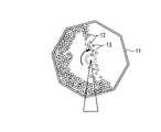
図9は転動体素材をバレル処理するときに用いる回転バレル装置の一例を示す図であり、同図に示される回転バレル装置を用いて転動体素材をバレル処理するときには、先ず、焼入焼戻しが施された多数の転動体素材13を正多角形状の鋼製バレル容器11内に投入すると共に、製造する転動体の直径(例えば直径:9.525mm)に対して150〜250%の直径(例えば直径:19.050mm)を有する多数の鋼球12を供材として鋼製バレル容器11内に投入した後、鋼製バレル容器11を回転させる。このとき、バレル容器11内に投入された転動体素材13のうちバレル容器11内の上部に位置する転動体素材13は重力落下し、バレル容器11内の下部に位置する転動体素材13や鋼球12に衝突することによってボールピーニングされる。
【0053】
上述した方法で製造された転動体の表面硬さ、残留オーステナイト、残留圧縮応力の各測定値を表3に示す。なお、残留オーステナイトの測定は転動体の表面を30μmまで電解研磨した後に行った。また、残留応力の測定は転動体の表面を30μmづつ電解研磨した後に行い、転動体の表面から480μmまでを測定した。
【0054】
【表3】
表3において、実施例11〜16は焼入温度:820℃〜900℃、第一次焼戻温度:80℃〜130℃、第二次焼戻温度:180℃〜220℃の熱処理条件で製造された転動体(表面硬さ:Hv850〜Hv1000、残留オーステナイト:20体積%以下、残留圧縮応力:−500〜−1300MPa)を示している。また、比較例11は焼入温度:860℃、第一次焼戻温度:200℃の熱処理条件で製造された転動体(表面硬さ:Hv840〜Hv860、残留オーステナイト:6〜9体積%以下、残留圧縮応力:−600〜−800MPa)、比較例12は焼入温度:860℃、第二次焼戻温度:200℃の熱処理条件で製造された転動体(表面硬さ:Hv880〜Hv930、残留オーステナイト:4〜7体積%以下、残留圧縮応力:−710〜−910MPa)、比較例13〜16は焼入温度:860℃、第一次焼戻温度:150〜180℃、第二次焼戻温度:200℃の熱処理条件で製造された転動体(表面硬さ:Hv850〜Hv980、残留オーステナイト:5〜10体積%以下、残留圧縮応力:−650〜−900MPa)をそれぞれ示している。
【0056】
本発明者らは、表3に示した転動体(実施例11〜16及び比較例11〜16)を使用して玉軸受(型番6206、外径62mm、内径30mm、幅16mm)を作成し、回転数:4000min−1、ラジアル負荷荷重:7000N、潤滑油:タービン油(VG68)の試験条件にて各玉軸受の回転試験を行った。そして、各玉軸受の転動体に剥離が生じるまでの時間を測定し、ワイブルチャート図を用いて各玉軸受の90%残存寿命(L10)を求めた。その結果を表3に併記する。なお、軌道輪にはSCr420を使用し、浸炭窒化処理を行なったものを使用した。また、潤滑油には予めステンレス鋼からなる鉄粉(35μm以下の大きさ)を混入させ、潤滑油中の鉄粉をパーティクルカウンタで測定した。
【0057】
表3に示されるように、実施例11〜16のL10は、比較例11〜13のL10に比べて3〜9倍の高い数値を示している。また、各玉軸受のL10は表3に示される表面硬さ、残留オーステナイト、残留応力の値から得られる差だけでは推定できないものであり、この寿命差は加工誘起変態による非常に微細なマルテンサイト組織の存在と高密度の転位の導入によるものである。
【0058】
比較例12の転動体は、仕上げ検査の際に発見できなかった非常に小さいクラックが転動体表面に存在し、このクラックが進展して剥離に至ったため、寿命値が短いものとなった。比較例14の転動体はピーニングの際に直径19.050mmの鋼球の代わりに直径11.112mmの鋼球をバレル容器内に入れて製造されたものであり、この場合、製造対象の転動体(直径9.525mm)に対して相手の鋼球(直径11.112mm)が十分に大きくなくピーニングの効果が得られなかった。比較例15の転動体は直径19.050mmの鋼球の代わりに直径25.003mmの鋼球をバレル容器内に入れて製造されたものであり、この場合、製造対象の転動体(直径9.525mm)に対して相手の転動体(直径25.003mm)との差が大きいため、ピーニングの効果が得られなかった。比較例16の転動体は、ピーニングの際に異なるサイズの鋼球を入れなかったものである。
【0059】
転動体素材を回転バレル法でピーニング処理する際に径の異なる鋼球をバレル容器内に投入しないでバレル処理を行って得られた転動体(表3の比較例16)の残留圧縮応力特性を図10に、また転動体素材を回転バレル法でピーニング処理する際に製造しようとする転動体径の150〜250%の直径を有する鋼球をバレル容器内に投入してバレル処理を行って得られた転動体(表3の実施例4)の残留圧縮応力特性を図11にそれぞれ示す。
【0060】
図10に示されるように、転動体素材を回転バレル法でピーニング処理する際に径の異なる鋼球をバレル容器内に投入しないでバレルピーニング処理を行うと、残留圧縮応力のピーク値が存在する位置(転動体表面から280μmの深さ位置)よりも表面側では残留圧縮応力の値が小さくなっていることがわかる。これに対し、転動体素材を回転バレル法でピーニング処理する際に製造しようとする転動体径の150〜250%の直径を有する鋼球を研磨材としてバレル容器内に投入してバレルピーニング処理を行うと、図11に示されるように、残留圧縮応力のピーク位置より表面側の浅い位置であっても−800MPa程度の残留圧縮応力が得られることがわかる。
【0061】
以上の説明から明らかなように、高炭素クロム軸受鋼からなる転動体素材に焼入焼戻しを施し、次いで転動体素材をバレル処理した後、180℃〜220℃の温度で焼戻しを施すと、バレルピーニング処理で低下した転動体素材の靭性を向上させることができる。従って、軌道輪素材に割れ等がショットピーニング時に発生したり、転がり軸受として必要な靭性が不足したりすることを抑制でき、異物が混入した潤滑油中でも圧痕等の生じ難い耐久性に優れた転動体を得ることができる。
【0062】
次に図13乃至図15を参照して、本発明の第3の実施形態について説明する。
図13は本発明を軸受軌道輪の製造方法に適用した一実施形態を示す図であり、同図に示すように、本実施形態では、SUJ2等の高炭素クロム軸受鋼やSCr440などの軌道輪材料を鍛造および旋削して得られた軌道輪素材に浸炭窒化または浸炭焼入れを行い(硬化工程S21)、さらに焼入れによって生じた残留オーステナイトの分解を抑制するために、80℃〜130℃の温度で焼戻しを行った後(焼戻し工程S22)、図3に示すショットピーニング装置を用いて軌道輪素材にショットピーニングを行う(ショットピーニング工程S23)。ここで、軌道輪素材にショットピーニングを行う理由は、軌道輪素材に残留圧縮応力を付与し、残留オーステナイトをマルテンサイトに変態させて表面硬さを向上させるためであり、ショットピーニングを行った後は、軌道輪素材に対して180℃〜220℃の温度で高温焼戻しを行う(第二次焼戻し工程S24)。なお、軌道輪に高温焼戻しを施した後は、軌道輪素材に対して仕上げ加工を施す。
【0063】
このような方法で軸受軌道輪を製造すると、軌道輪の転動体軌道面から深さ0.05a(a:転動体の直径)mm程度の範囲の表層部に−500〜−1300MPaの残留圧縮応力が付与されると共に表層部の残留オーステナイトが実質的に3〜30vol%になり、また表層部の硬さがHv800〜1000になるので、異物が混入した潤滑油中でも耐圧痕性および耐摩耗性に優れた軸受軌道輪を得ることができる。
図13に示した方法で製造された軌道輪の表層部における仕上り硬さ、最大残留応力、残留オーステナイト量を表4に示す。
【0064】
【表4】
表4において、実施例21〜26および比較例21〜26の各軌道輪は、いずれもSUJ2またはSCr440からなるものである。また、実施例21〜26の各軌道輪は図12に示した方法で製造されたものであるが、比較例21はショットピーニングを行わずに通常の焼入れ焼戻しで製造された軌道輪、比較例22は浸炭窒化または浸炭焼入れを行わずに製造された軌道輪、比較例23はショットピーニング後に第二次焼戻しを行わずに製造された軌道輪、比較例24はショットピーニングの前に焼戻しを行わずに製造された軌道輪、比較例25及び26はショットピーニング後に第二次焼戻しを行わずに製造された軌道輪である。
【0066】
図14及び図15に、実施例21の表層部における残留圧縮応力とビッカース硬さを測定した結果を示す。表4及び図15から明らかなように、実施例21の軌道輪は、比較例21のものと比較して、表層部の硬さがHv850〜Hv870と非常に硬いので、異物が混入した潤滑油中で使用しても異物による表面圧痕の発生を抑制することができる。また、表4及び図14から明らかなように、実施例21の軌道輪は、比較例21のものと比較して、表層部の残留圧縮応力が−1150〜−1200MPaと非常に高いので、潤滑油中の異物によって表面に圧痕が発生した場合でも圧痕を起点とする亀裂の発生を防止することができる。また、ショットピーニングによって表層部の残留オーステナイトだけをマルテンサイトに変態させるので、表層部より内側の部分には残留オーステナイトが存在し、軸受として必要な靭性を確保することができる。
【0067】
本発明者らは、表4に示した軌道輪(実施例21〜26および比較例21〜26)を使用して深溝玉軸受(型番6206、外径62mm、内径30mm、幅16mm)を作成し、使用試験機名:日本精工(株)製回転試験機、回転数:2000min−1、ラジアル負荷荷重:6240N、潤滑:異物入り潤滑の試験条件にて各玉軸受の寿命転試験を行った。そして、各玉軸受の軌道輪に剥離が生じるまでの時間を軸受寿命として測定し、ワイブルチャート図を用いて各玉軸受の90%残存寿命(L10)を求めた。その結果を表5に示す。なお、潤滑油には予めステンレス鋼からなる鉄粉(35μm以下の大きさ)を混入させ、潤滑油中の鉄粉をパーティクルカウンタで測定した。
【0068】
【表5】
表5から明らかなように、実施例21〜26の各軌道輪は、表層部硬さおよび最大残留圧縮応力が高く、適当な残留応力があり、寿命比が比較例21の7〜11倍以上になっている。比較例22〜26については、寿命比が比較例21の2〜3倍になっているが、実施例21〜26に比べて靭性が低いため、寿命の向上の度合も小さい。なお、比較例24は、ショットピーニングで表面にクラックが生じていて使用不可能であった。
【0070】
したがって、浸炭窒化または浸炭焼入れされた軌道輪素材に80℃〜130℃の温度で焼戻しを施し、次いでショットピーニングを行った後、軌道輪素材に180℃〜220℃の温度で焼戻しを施すことで、耐圧痕性および耐摩耗性に優れた軌道輪を得ることができる。
図16は本発明を軸受転動体の製造方法に適用した一実施形態を示す図であり、本実施形態では、SUJ2等の高炭素クロム軸受鋼からなるコイル状の線材を打出し機で一定長さに切断し、切断された線材を常温で圧縮成形して得られた転動体素材に対して820℃〜900℃の温度で浸炭または浸炭窒化を行った後、焼入れを行なう(焼入工程S31)。次に、焼入れされた転動体素材に130℃以下の温度で低温焼戻しを行った後(焼戻し工程S32)、転動体素材にバレルピーニングを施す(バレルピーニング工程S33)。
【0071】
具体的には、図9に示す正多角形状の鋼製バレル容器11内に焼入れ後の転動体素材(鋼球)13を投入するとともに、製造する転動体の直径(例えば直径:9.525mm)に対して150〜250%の直径(例えば直径:19.050mm)を有する多数の鋼球12を供材として鋼製バレル容器11内に投入する。そして、鋼製バレル容器11を回転させ、バレル容器11内に投入された転動体素材13の表面に鋼球12を衝突させて転動体素材13の表面を表面硬化処理する。そして、転動体素材の表面をバレルピーニング法で表面硬化処理したならば、次に転動体素材に対して180℃〜220℃の温度で高温焼戻しを行い(焼戻し工程S34)。なお、転動体素材に高温焼戻しを施した後は、転動体素材に対して研削および研磨仕上げを行なう。
このような方法で製造された転動体の仕上り硬さ、最大残留応力、残留オーステナイトを表6及び表7に示す。
【0072】
【表6】
【表7】
表6及び表7において、実施例31〜42は浸炭焼入温度:820℃〜960℃、第一次焼戻温度:110℃〜120℃、第二次焼戻温度:180℃〜220℃の熱処理条件で製造された転動体(表面硬さ:Hv830〜Hv1000、残留オーステナイト:20体積%以下、残留圧縮応力:−500〜−1000MPa)を示している。また、比較例31は浸炭焼入温度:950℃、第一次焼戻温度:200℃の熱処理条件で製造された転動体(表面硬さ:Hv820〜Hv860、残留オーステナイト:15〜20体積%、残留圧縮応力:−620〜−780MPa)、比較例32は浸炭焼入温度:950℃、第二次焼戻温度:200℃の熱処理条件で製造された転動体(表面硬さ:Hv970〜Hv1010、残留オーステナイト:21〜26体積%、残留圧縮応力:−900〜−980MPa)、比較例33〜36は浸炭焼入温度:950℃、第一次焼戻温度:110〜180℃、第二次焼戻温度:200℃の熱処理条件で製造された転動体(表面硬さ:Hv920〜Hv980、残留オーステナイト:15〜28体積%以下、残留圧縮応力:−570〜−850MPa)、比較例37は浸炭焼入温度:860℃、第一次焼戻温度:200℃の熱処理条件で製造された転動体(表面硬さ:Hv780〜Hv830、残留オーステナイト:16〜22体積%、残留圧縮応力:−480〜−530MPa)、比較例38は浸炭焼入温度:860℃、第二次焼戻温度:200℃の熱処理条件で製造された転動体(表面硬さ:Hv910〜Hv970、残留オーステナイト:16〜21体積%、残留圧縮応力:−800〜−880MPa)、比較例39〜42は浸炭焼入温度:860℃、第一次焼戻温度:110〜180℃、第二次焼戻温度:200℃の熱処理条件で製造された転動体(表面硬さ:Hv790〜Hv960、残留オーステナイト:17〜27体積%、残留圧縮応力:−380〜−890MPa)である。なお、比較例32の転動体は、ショットピーニング時に表面にクランクが生じているものがあり、作製した転動体のうち60%のものは使用不可能であった。
【0075】
本発明者らは、表6及び表7に示した転動体(実施例31〜42及び比較例31〜42)を使用して玉軸受(型番6206、外径62mm、内径30mm、幅16mm)を作成し、回転数:2000min−1、ラジアル負荷荷重:6240N、潤滑油:タービン油(VG68)の試験条件にて各玉軸受の回転試験を行った。そして、各玉軸受の転動体に剥離が生じるまでの時間を測定し、ワイブルチャート図を用いて各玉軸受の90%残存寿命(L10)を求めた。その結果を表6および表7に併記する。なお、軌道輪にはSCr420を使用し、浸炭窒化処理を行なったものを使用した。また、潤滑油には予めステンレス鋼からなる鉄粉(35μm以下の大きさ)を混入させ、潤滑油中の鉄粉をパーティクルカウンタで測定した。
【0076】
実施例31〜42の転動体は、比較例31〜42に対して2倍から8倍の寿命値が得られている。この結果は表6に示される転動体の硬さ、残留オーステナイト、残留応力の値から得られる差だけでは推定できないものである。この寿命差は、加工誘起変態による非常に微細なマルテンサイト組織の存在と高密度の転位の導入によるものだからである。
【0077】
比較例32及び38については、仕上げ検査の際に発見できなかった非常に小さいクラックが転動体表面に存在し、このクラックが進展して剥離に至ったため、寿命値が短いものとなった。
比較例34及び40はバレルピーニングの際に直径12.700mmの鋼球を使用して製造されたものであり(通常は直径19.050mmの鋼球を使用)、この場合、製造対象の転動体(9.525mm径)に対して鋼球の径が大きくないため、ピーニングの効果が得られなかった。
【0078】
比較例35及び41はバレルピーニングの際に直径25.400mmの鋼球を使用して製造されたものであり、この場合、製造対象の転動体(9.525mm径)に対して鋼球の径が大き過ぎるため、ピーニングの効果が得られなかった。
比較例36及び42はバレルピーニングの際にサイズの異なる鋼球を使用しないで製造されたものであり、この例では表面近傍の残留応力が小さかったために寿命が短かった。
【0079】
したがって、浸炭窒化または浸炭焼入れされた転動体素材に80℃〜130℃の温度で焼戻しを施し、次いでショットピーニングを行った後、転動体素材に180℃〜220℃の温度で焼戻しを施すことで、耐圧痕性および耐摩耗性に優れた転動体を得ることができる。
なお、上述した各実施形態では本発明を軸受部品の製造方法に適用した場合を説明したが、本発明はこれに限定されるものではなく、たとえばボールねじ部品或いはリニアガイド部品の製造方法にも適用できることは勿論である。
【0080】
【発明の効果】
以上説明したように、本発明によれば、必要な表面硬さを有し、靭性が高く、しかも表面の耐圧痕性、耐摩耗性に優れ、亀裂の進展に対して強く、高面圧下で異物が混入した潤滑油中でも転がり疲労寿命を向上させることのできる転動装置部品を製造することができる。
【図面の簡単な説明】
【図1】本発明の第1の実施形態に係る軸受軌道輪の製造方法を説明するための図である。
【図2】図1の焼入工程、第一次焼戻し工程および第二次次焼戻し工程における熱処理温度を示す図である。
【図3】軌道輪素材のショットピーニング加工に使用されるショットピーニング加工装置の一例を示す図である。
【図4】図1に示した方法で製造された軌道輪の表層部における硬さの測定値を示す図である。
【図5】図1に示した方法で製造された軌道輪の表層部における残留圧縮応力の測定値を示す図である。
【図6】本発明の第2の実施形態に係る軸受転動体の製造方法を説明するための図である。
【図7】図9の焼入工程および第一次焼戻し工程における熱処理温度を示す図である。
【図8】図9の第二次焼戻し工程における焼戻温度を示す図である。
【図9】転動体素材をバレル処理するときに用いる回転バレル装置の一例を示す図である。
【図10】転動体素材を回転バレル法でピーニング処理する際に径の異なる転動体素材をバレル容器内に投入しないでバレル処理を行って得られた転動体の残留圧縮応力特性を示す線図である。
【図11】転動体素材を回転バレル法でピーニング処理する際に製造しようとする転動体径の50〜80%の直径を有する転動体素材をバレル容器内に投入してバレル処理を行って得られた転動体の残留圧縮応力特性を示す線図である。
【図12】転がり軸受の概略構成を示す図である。
【図13】本発明の第3の実施形態に係る軸受軌道輪の製造方法を説明するための図である。
【図14】本発明の第3の実施形態に係る方法で製造された軸受軌道輪の表層部における残留圧縮応力の測定値を示す図である。
【図15】本発明の第3の実施形態に係る方法で製造された軸受軌道輪の表層部における硬さの測定値を示す図である。
【図16】本発明の第4の実施形態に係る軸受転動体の製造方法を説明するための図である。
【符号の説明】
1 外側軌道輪
1a 転動体軌道溝
2 内側軌道輪
2a 転動体軌道溝
3 転動体
11 バレル容器
12 供材(鋼球)
13 転動体素材[0001]
TECHNICAL FIELD OF THE INVENTION
The present invention relates to a method for manufacturing a rolling device component such as a rolling bearing, a ball screw, and a linear guide.
[0002]
[Prior art]
Rolling bearings such as ball bearings used in transmissions and engines of automobiles, agricultural machines, construction machines, steel machines, etc., as shown in FIG. 12, have outer races having rolling
[0003]
When a rolling bearing is used in clean lubricating oil in which foreign matter such as abrasion powder is not mixed, the bearing life is usually governed by separation from the position of the shear stress on the surface of the raceway groove due to the internal starting point. However, when foreign matter is mixed in the lubricating oil, it is governed by peeling and the surface wear of the raceway groove surface starting from the indentation on the raceway groove surface. The fatigue life of the bearing ring is greatly reduced. Therefore, in order to prolong the life of the bearing when foreign matter is mixed in the lubricating oil, it is necessary to obtain a bearing ring having excellent indentation resistance and wear resistance on the surface of the raceway groove.
[0004]
A raceway of a rolling bearing used under lubrication mixed with foreign matter as described above is required to have high toughness and to prevent indentation and wear by foreign matter. However, increasing the toughness and increasing the hardness are generally contradictory, and it is very difficult to obtain a bearing component such as a bearing ring having both excellent performances. Therefore, as a method for obtaining bearing parts such as race rings having high toughness and excellent surface indentation resistance and abrasion resistance, quenching is performed on a bearing part material made of high carbon chromium bearing steel, and then a desired bearing part material is obtained. Patent Document 1 discloses a method in which shot peening is applied to a part to impart residual stress, transforms residual austenite into martensite, increases hardness, and then tempers the bearing component material.
[0005]
Various alloy steels such as bearing steel type 2 (SUJ2) are known as bearing materials for rolling bearings used in transmissions, engines, and the like of automobiles, agricultural machines, construction machines, steel machines, and the like. Rolling bearings such as those described above tend to increase the load surface pressure of the bearing due to an increase in the load accompanying a recent improvement in the performance of the machine and a reduction in the size of the bearing, and there is a demand for an improvement in the durability life. Further, since rolling bearings are repeatedly subjected to shear stress under a high surface pressure, it is necessary to ensure a rolling fatigue life that can withstand the shearing force. In order to extend the life of the rolling bearing, it is important to make the surface hardness of the rolling element a desired value, and at the same time, to give a height relationship between the surface hardness of the rolling element and the surface hardness of the bearing ring. If the rolling bearing is used under conditions such as high contact pressure, insufficient oil film formation, both radial load and thrust load, or lubrication with foreign matter, This is because flaking occurs on the surface of the rolling element earlier than before. However, if the surface hardness of the rolling elements is lower than the surface hardness of the race, or if the surface hardnesses of the two are the same, early peeling occurs intensively on the rolling elements, greatly reducing the bearing life.
[0006]
Therefore, high carbon chromium bearing steel is used as a bearing material, and when it is quenched and tempered, the tempering temperature of the rolling elements is set to 140 ° C to 145 ° C, and the tempering temperature of the raceway is set to 160 ° C to 180 ° C. By tempering, the surface hardness of the rolling elements is increased by about 1 to 2 in terms of HRC compared to the surface hardness of the bearing rings, and a height relationship is given to the surface hardness of the rolling elements and the surface hardness of the bearing rings. There is known a conventional example in which the life of a rolling bearing is improved.
[0007]
However, in the conventional example described above, the tempering temperature of the rolling element is suppressed to about 20 to 40 ° C. lower than the tempering temperature of the bearing ring, and the tempering is performed. Since the surface hardness difference between the bearing ring and the bearing ring is obtained, the surface hardness of the rolling elements is improved, but the improvement in the toughness required for the impact strength to be imparted in the tempering process and the strength against repeated loads is sufficient. Not done. For this reason, there is a problem that a crack is generated from a damaged portion caused by a foreign substance existing in the lubricating oil, and that the starting point causes early flaking, thereby greatly reducing the life of the rolling bearing. Further, when the tempering temperature of the rolling element is suppressed to 140 ° C. to 145 ° C., when the rolling bearing is used at a quasi-high temperature or a high temperature condition, the retained austenite is transformed into martensite, and as a result, the dimensional change is caused. And internal distortion are liable to occur, and the dimensional stability of the bearing is reduced.
[0008]
In order to solve such problems, rolling elements made of high-carbon chromium steel, carburized steel, high-speed steel for high-temperature bearings, martensitic stainless steel, etc. are tempered at a temperature of 180 to 220 ° C. Is disclosed in
[0009]
[Patent Document 1]
JP-A-5-195069
[Patent Document 2]
JP-A-9-170624
[Patent Document 3]
JP-A-5-195070
[Patent Document 4]
JP-A-5-163526
[0010]
[Problems to be solved by the invention]
The method for manufacturing a bearing component disclosed in Patent Document 1 is a method in which shot peening is performed on a quenched bearing component material and then tempering. Therefore, cracks and the like occur in the bearing component material during shot peening, and toughness is reduced. There were problems such as running short. Patent Document 1 discloses a method of performing tempering before performing shot peening on a bearing component material, but in this case, there is a problem that the hardness is not sufficiently improved.
[0011]
The method disclosed in
In the method disclosed in
In addition, the method disclosed in
[0012]
The present invention has been made in view of such problems, and has a high toughness, excellent surface dent resistance and abrasion resistance, and a bearing life in a lubricating oil mixed with foreign matter at a high surface pressure. It is an object of the present invention to provide a method of manufacturing a rolling device component capable of obtaining a rolling device component capable of improving the performance. Further, the present invention provides a rolling device having high toughness, excellent surface indentation resistance and abrasion resistance, and capable of improving bearing life in lubricating oil mixed with foreign matter at a high surface pressure. With the goal.
[0013]
[Means for Solving the Problems]
In order to achieve the above object, a method of manufacturing a rolling device component according to the first aspect of the present invention hardens a rolling device component material made of high-carbon chromium bearing steel by hardening the component material. A quenching step, a primary tempering step of tempering the component material after the quenching step, and a mechanical surface hardening process of mechanically hardening a desired portion of the component material after the primary tempering step And a second tempering step of tempering the component material after the mechanical surface hardening step.
[0014]
According to a second aspect of the present invention, in the method for manufacturing a rolling device component according to the first aspect, the component material is tempered at a tempering temperature of 80 ° C to 130 ° C in the first tempering step. .
According to a third aspect of the present invention, in the method for manufacturing a rolling device component according to the first or second aspect, the component material is tempered at a tempering temperature of 180 ° C to 220 ° C in the second tempering step. And
[0015]
According to a fourth aspect of the present invention, in the method for manufacturing a rolling device part according to any one of the first to third aspects, the mechanical surface hardening step includes a step of shot peening the component material. I do.
According to a fifth aspect of the present invention, in the method for manufacturing a rolling device component according to any one of the first to third aspects, the mechanical surface hardening process includes a step of performing barrel peening on a rolling element material of the rolling device. It is characterized by being.
[0016]
According to a sixth aspect of the present invention, in the method of manufacturing a rolling device component according to the fifth aspect, the step of performing barrel peening on the rolling element material comprises a step of reducing a diameter of 150 to 250% of a rolling element diameter of the rolling element. A step of subjecting the rolling element material to barrel peening with a large number of steel balls.
According to a seventh aspect of the present invention, in the method for manufacturing a rolling device component according to the fourth aspect, the shot peening reduces the residual austenite of the component material to 80% or less of that before the shot peening and reduces the hardness by shot peening. It is characterized by being improved to Hv50 or more than before processing.
[0017]
The method of manufacturing a rolling device part according to the invention of claim 8 includes a step of quenching the rolling device component material after carburizing or carbonitriding the rolling device component material made of steel; A primary tempering step of tempering the component material after the quenching step, a mechanical surface hardening step of mechanically surface hardening the component material after the primary tempering step, and the mechanical surface hardening And a second tempering step of tempering the component material after the processing step.
[0018]
According to a ninth aspect of the present invention, in the method of manufacturing a rolling device component according to the eighth aspect, the mechanical surface hardening process includes a barrel peening process of barrel peening a component material of the rolling device. Features.
According to a tenth aspect of the present invention, in the method for manufacturing a rolling device part according to the eighth or ninth aspect, the residual austenite amount of the component material is set to 3 to 30 vol%, and the maximum compressive stress of the component material is set to -500 to-. It is characterized by being 1300 MPa.
[0019]
According to an eleventh aspect of the present invention, in the method for manufacturing a rolling device part according to the ninth aspect, the residual austenite amount of the component material is set to 40 to 80% of the residual austenite amount before the barrel peening process. It is characterized by.
According to a twelfth aspect of the present invention, in the method for manufacturing a rolling device part according to any one of the eighth to eleventh aspects, the surface hardness of the component material is Hv800 or more.
[0020]
According to a thirteenth aspect of the present invention, there is provided a rolling device including a rolling device part manufactured by the manufacturing method according to any one of the first to twelfth aspects.
The present inventors have conducted detailed studies on the effects and effects of the shot peening treatment, and as a result, have found a method that is most effective in improving the rolling fatigue life.
[0021]
In the shot peening process, the retained austenite present in the surface layer of the bearing component material is transformed into martensite by work-induced transformation to improve the surface hardness of the bearing component material. The martensite structure obtained at this time is not only very fine compared to the martensite structure obtained at the time of heat treatment, ie, quenching, but also introduces high-density dislocations. Such a structure is not only very hard, but also very useful for fatigue strength and rolling fatigue life. In addition, indentations and abrasion due to foreign matter are unlikely to occur. In addition, since the residual compressive stress is applied to the surface layer of the bearing component material by the shot peening process, even if an indentation is generated on the surface of the bearing component material, the growth of a crack originating from the indentation can be suppressed. In addition, since only the retained austenite present in the surface layer of the bearing component material is transformed into martensite by shot peening, residual austenite exists in the portion inside the surface layer of the bearing component material, and the required toughness for the bearing is reduced. Can be secured.
[0022]
Before and after the shot peening step, the bearing component material is tempered. The reason for performing the tempering before the shot peening step is to recover the decrease in toughness due to quenching, and thereby it is possible to prevent cracks and the like from occurring in the bearing component material during shot peening. However, tempering is performed at a temperature lower than the tempering temperature before finishing because it is tempering to prevent cracks and the like during shot peening.
[0023]
The reason for performing the tempering after the shot peening step is to improve the toughness of the bearing component material reduced by the shot peening and to remove the unevenness of the residual stress. By this tempering, the structure of the bearing component material becomes uniform, and the life of the rolling bearing can be improved. The residual compressive stress applied to the surface layer portion of the bearing component material in the shot peening step is partially relaxed and stabilized by the subsequent tempering step. For this reason, it is desirable that the residual compressive stress applied in the shot peening step be slightly higher than the final target value. Further, the hardness of the surface layer portion hardened by the shot peening process is slightly reduced by the subsequent tempering process. Therefore, it is desirable that the hardness is slightly higher than the final target value in the shot peening process.
[0024]
If the residual austenite present in the surface layer of the bearing component exceeds 20% by volume, sufficient surface hardness and residual compressive stress cannot be obtained. Therefore, when shot peening the bearing component material, it is desirable to perform the shot peening so that the residual austenite present in the surface layer of the bearing component material is substantially 20% by volume or less.
[0025]
If the maximum residual compressive stress of the surface layer of the bearing component is less than -500 MPa, the bearing life cannot be sufficiently extended. On the other hand, when the maximum residual compressive stress exceeds -1300 MPa, the material of the bearing component is greatly consumed at the time of shot peening, the processing time becomes longer, and the cost may be increased. Therefore, when performing shot peening of the bearing component material, it is desirable to perform shot peening so that the maximum residual compressive stress at the surface layer of the material is -500 to -1300 MPa.
[0026]
If the surface hardness of the bearing component is lower than Hv800, indentations due to foreign matter are likely to occur, and it is not possible to expect a longer life of the bearing. When the surface hardness of the bearing component exceeds Hv1000, the toughness of the bearing component decreases. Therefore, when shot peening the bearing component material, it is desirable to perform the shot peening so that the surface hardness of the bearing component material is Hv800 to Hv1000.
[0027]
The present inventors have conducted detailed studies on the effects and effects of barrel peening, and have found a method that is most effective in improving the rolling fatigue life. That is, conventionally, barrel peening has been performed after quenching and tempering, but the effect obtained by performing this after quenching increases. This is because the barrel peening process transforms the retained austenite present in the surface layer of the rolling element into a martensite structure by work-induced transformation, but the martensite structure obtained at that time is different from the martensite structure obtained at the time of heat treatment, that is, at the time of quenching. In addition to being very fine, a high density of dislocations is introduced. Such a structure is not only very hard but also very useful for fatigue strength, that is, rolling fatigue. The greater the martensite structure due to such processing-induced transformation, the more advantageous the fatigue strength. For that purpose, the larger the amount of retained austenite before the shot peening treatment, the better. In the case where shot peening was performed before tempering, the ratio of the martensite structure generated by work hardening was larger than in the case where shot peening was performed after tempering, and the effect of improving fatigue strength was obtained.
[0028]
When performing barrel peening on the rolling element material, when a number of steel balls having a diameter of 150 to 250% of the diameter of the rolling element to be manufactured are put in a steel barrel container as an abrasive, and barrel peening is performed, The peening effect works more effectively. That is, since steel balls having different diameters collide in the barrel container, the effect of peening appears on the surface side on the steel ball side with a larger diameter and on the inner surface side on the steel ball side with a smaller diameter. Further, by colliding with a steel ball having a large diameter, a larger residual stress can be obtained. In the steel ball of the bearing, a long life effect can be obtained by making the microstructure of the steel closer to the surface finer and having a higher dislocation density.
[0029]
In addition, when peening is performed after quenching, cracks are likely to occur. Therefore, peening cracks can be prevented by performing low-temperature tempering after quenching, that is, tempering at 130 ° C. or lower. In this case, transformation of retained austenite due to low-temperature tempering is hardly observed, and the effect of the present invention can be sufficiently obtained. Here, the difference from the conventional method will be described in detail. As a method of hardening the surface of the rolling element for bearing, a typical method is disclosed in Japanese Patent Publication No. 1-12813. That is, this method is a method in which after hardening and tempering a steel ball made of hardened steel, a barrel treatment is performed to harden the steel ball surface.
[0030]
In addition, the present inventors have conducted detailed studies on the effects and effects of the heat treatment and the shot peening treatment, and as a result, have found a method that is most effective in improving the rolling fatigue life. In particular, by giving carburizing or carbonitriding to at least the raceway surface to increase the carbon content and the nitrogen content of the raceway surface, to impart a solid solution strengthening effect of carbon and nitrogen and a tempering softening resistance of nitrogen to the raceway surface. And the surface hardness can be improved. For this reason, even if the bearing ring is tempered at a normal tempering temperature (180 to 220 ° C.) after shot peening, the required surface hardness and toughness improvement of the bearing ring can be imparted.
[0031]
Further, in carbonitriding, since carbon and nitrogen form a solid solution in the carbonitrided material, the effect of solid solution strengthening is greater than, for example, carburizing. Furthermore, nitrogen has tempering softening resistance, and can make the surface of the carbonitrided material harder. In addition, for example, the bearing can be tempered at a high temperature, and the dimensional stability and long life are impaired even when the bearing is used at a temperature from a quasi-high temperature to a high temperature (100 to 200 ° C.) as well as at a normal temperature. There is no.
In carbonitriding, carbon and nitrogen are dissolved so that the amount of solid solution nitriding of the surface hardened layer falls within the above range and the amount of surface carbon solid solution becomes 1.2 to 1.6% by weight. Is preferred.
[0032]
By the shot peening process, the retained austenite in the surface layer of the bearing component material is subjected to work-induced transformation into martensite to increase the hardness. The martensite structure obtained at this time is not only very fine compared to the martensite structure obtained at the time of heat treatment, that is, quenching, but also a high-density transition is introduced. Such a structure is not only very hard but also very useful for fatigue strength and rolling fatigue. In addition, indentations and abrasion due to foreign matter are less likely to occur. Moreover, since a residual compressive stress is applied to the surface layer by the shot peening step, even when an indentation is generated, the growth of a crack originating from the indentation can be suppressed. Further, since only the retained austenite in the surface layer is transformed into martensite by shot peening, the retained austenite exists in a portion inside the surface layer, and the toughness required for a bearing can be obtained. For these reasons, it is desirable to transform as much retained austenite into martensite as possible during shot peening.
[0033]
The present inventors have intensively studied to obtain sufficient hardness and residual compressive stress. As a result, it was found that the bearing performance was particularly improved when the residual austenite was reduced by shot peening to 80% or less of that before processing and the hardness was increased by Hv50 or more from that before processing. The reason for reducing the retained austenite to 80% or less before processing is that if it exceeds 80%, sufficient hardness and generation of residual compressive stress cannot be obtained. Excessive retained austenite may cause deformation during use. The reason why the hardness is increased by Hv50 or more from that before processing is to obtain sufficient hardness. Unless the hardness is increased, it is difficult to suppress the generation of indentations.
[0034]
Tempering is performed before and after the shot peening step. The tempering after the quenching and before the shot peening is for recovering the decrease in toughness due to the quenching. This tempering can prevent cracking during shot peening. However, since the tempering is performed for shot peening, the tempering is performed without raising the temperature as much as the tempering before finishing. This is to prevent a reduction in retained austenite due to tempering. For SUJ2, 80 to 130 ° C is appropriate.
[0035]
Similarly, the reason why the tempering is performed after the shot peening and before the finishing step is to improve the toughness and remove the unevenness of the residual stress. By this tempering, the structure of the finished product becomes uniform and the life is extended. The residual compressive stress applied to the surface layer of the bearing component in the shot peening step is partially relaxed by the subsequent tempering step, and is stabilized. For this reason, the residual compressive stress applied in the shot peening step is set slightly higher than the final target value. Also, the hardness of the surface layer portion increased in the shot peening step is slightly reduced by the subsequent tempering step, so the hardness is set slightly higher than the final target value in the shot peening step.
[0036]
The retained austenite is desirably substantially 3 vol% or more and 30 vol% or less. If it is less than 3%, the indentation resistance is inferior. If it exceeds 30 vol%, sufficient surface hardness and residual compressive stress cannot be obtained.
The reason for setting the maximum residual compressive stress to -500 to -1300 MPa is that if it is less than -500 MPa, a sufficient improvement in bearing life cannot be obtained. This is because the wear is severe, the processing time is prolonged, and the cost is increased. Further, when a high load is applied, the steel is further compressed, which may cause deformation and breakage.
Furthermore, the reason for setting the hardness in the range of Hv800 to 1000 in Vickers hardness is that if the hardness is lower than Hv800, the effect of suppressing the generation of indentations in the surface layer portion is not sufficient, and the life of the bearing is not improved. Further, if it exceeds Hv1000, the toughness decreases.
[0037]
BEST MODE FOR CARRYING OUT THE INVENTION
Hereinafter, embodiments of the present invention will be described with reference to the drawings.
FIG. 1 is a view showing an embodiment in which the present invention is applied to a method for manufacturing a bearing race. As shown in FIG. 1, in this embodiment, high carbon chromium bearing steel such as SUJ2 is forged and turned. After quenching the obtained bearing ring material at a temperature of 820 ° C. to 900 ° C. (quenching step S1), the bearing ring material is tempered at a temperature of 80 ° C. to 130 ° C. (first tempering step S2). . Next, a residual compressive stress of -500 to -1300 MPa is applied to the surface layer portion of the bearing ring material (a layer having a depth of 0.05 amm from the surface of the bearing ring material when the diameter of the rolling elements is amm) and the surface layer is formed. After the shot ring peening process is performed on the raceway material by the apparatus shown in FIG. 3 (shot peening step S3) so that the retained austenite in the part is substantially 20 vol% or less (180 ° C. to 220 ° C.). High-temperature tempering is performed at a temperature (second tempering step S4). After high-temperature tempering is applied to the bearing ring material, a polishing finish process is applied to the bearing ring material.
[0038]
Here, the reason why the quenched raceway material is tempered before shot peening is to recover the decrease in toughness due to quenching and prevent cracks and the like from occurring in the raceway material during shot peening. Further, the reason why the primary tempering temperature of the bearing ring material is set to 80 to 130 ° C. is that if the primary tempering temperature is lower than 80 ° C., the toughness reduced by quenching cannot be sufficiently recovered, and If the primary tempering temperature exceeds 130 ° C., the decomposition of the retained austenite proceeds. Therefore, the tempering before shot peening is desirably performed in the range of 80 ° C. to 130 ° C., as shown in FIG.
[0039]
The reason why tempering is performed on the bearing ring material after shot peening is to improve the toughness of the bearing ring material and remove unevenness in residual stress. At this time, if the tempering temperature of the bearing ring material is lower than 180 ° C., the dimensional stability of the bearing is reduced, and if the tempering temperature is higher than 220 ° C., the hardness is reduced and the life is shortened. Therefore, the tempering after shot peening is desirably performed in the range of 180 ° C. to 220 ° C. as shown in FIG.
[0040]
FIG. 3 is a view showing an example of a shot peening apparatus used for shot peening of a raceway material. The shot peening apparatus shown in FIG. 1 includes a
The finished hardness, maximum residual stress, and residual austenite amount (γR ) Are shown in Table 1.
[0041]
[Table 1]
In Table 1, Examples 1 to 5 show the orbits manufactured by performing tempering on the orbital ring material once before shot peening and once after shot peening. Comparative Example 1 is a raceway manufactured without performing shot peening on the raceway material, and Comparative Example 2 is a raceway ring manufactured by performing tempering on the raceway material before the shot peening. Comparative
[0043]
FIG. 4 is a diagram showing hardness characteristics of a surface layer portion of a bearing ring manufactured by the method shown in FIG. 1 (for example, Example 2 in Table 1). As shown in FIG. On the other hand, when the shot peening process is performed, the hardness of the raceway surface becomes very hard. Therefore, even when used in lubricating oil mixed with foreign matter, dents and the like are hardly generated in the raceway groove of the rolling element, and the generation of cracks originating from scratches and dents on the surface of the raceway can be prevented. .
[0044]
FIG. 5 is a diagram showing residual compressive stress characteristics in a surface layer portion of a bearing ring manufactured by the method shown in FIG. 1 (for example, Example 2 in Table 1). As shown in FIG. When the shot peening process is performed on the surface ring, residual compressive stress is applied to the surface layer of the bearing ring, and the residual compressive stress suppresses the growth of a crack. Therefore, even if a crack originating from an indentation generated on the surface of the bearing ring is generated in the bearing ring, the growth of the crack can be suppressed, and the life of the rolling bearing in lubricating oil mixed with foreign matter can be extended. it can. Further, only the retained austenite in the surface layer of the bearing ring is transformed into martensite by shot peening. Therefore, since the retained austenite is present in a portion inside the surface layer portion of the bearing ring, the toughness required for the bearing can be secured.
[0045]
The present inventors prepared ball bearings (model number 6206, outer diameter 62 mm, inner diameter 30 mm, width 16 mm) using the bearing rings (Examples 1 to 5 and Comparative Examples 1 to 3) shown in Table 1, Use test machine name: Nippon Seiko Co., Ltd. rotation test machine, rotation speed: 4000 min-1 The life rolling test of each ball bearing was performed under the following test conditions: load: 7000 N; lubrication: lubrication with foreign matter. Then, the time until the bearing ring of each ball bearing peeled was measured as the bearing life, and the bearing life of each ball bearing was compared and evaluated with the bearing life of Comparative Example 1 as 1. Table 2 shows the evaluation results.
[0046]
[Table 2]
As shown in Table 2, the races of Examples 1 to 3 have high surface layer hardness and high maximum residual compressive stress, and have a life ratio of 8 to 11 times or more as compared with the race of Comparative Example 1. I have. Although the life ratio of Comparative Example 2 is three times that of Comparative Example 1, the degree of improvement in bearing life is small because the toughness is lower than in Examples 1 to 5. Comparative Example 3 was unusable because cracks occurred on the surface of the bearing ring during shot peening.
[0048]
As is clear from the above description, when manufacturing the bearing ring of a rolling bearing, by performing tempering on the bearing ring material before and after shot peening, cracks and the like occur in the bearing ring material during shot peening. In addition, shortage of toughness required as a rolling bearing can be suppressed. Therefore, it is possible to obtain a raceway excellent in durability, in which indentations and the like hardly occur even in lubricating oil mixed with foreign matter.
[0049]
Next, a second embodiment of the present invention will be described with reference to FIGS.
FIG. 6 is a diagram showing an embodiment in which the present invention is applied to a method for manufacturing a rolling element for a bearing. As shown in FIG. 6, in the present embodiment, a coil-shaped coil made of high carbon chromium bearing steel such as SUJ2 is used. After the wire is cut into a fixed length by a punching machine, and the cut wire is compression-molded at room temperature, the rolling element material obtained is quenched at a temperature of 820 ° C. to 900 ° C. (quenching step S11). The rolling element material is tempered at a temperature of 80 to 130 ° C (first tempering step S12). Next, after the rolling element material is barrel-peened by the apparatus shown in FIG. 9 (barrel peening step S13), the rolling element material is subjected to high-temperature tempering at a temperature of 180 ° C. to 220 ° C. (second tempering step S14). . After the rolling element material is subjected to high-temperature tempering, the rolling element material is polished.
[0050]
When a rolling element of a rolling bearing is manufactured by such a method, a rolling element having a surface hardness of Hv800 to Hv1000, a residual austenite of a surface layer portion of 30% by volume or less, and a residual compressive stress of a surface layer portion of -500 MPa or more and less than -1000 MPa is obtained. Obtainable.
Here, the reason for setting the surface hardness of the rolling element to be equal to or higher than Hv800 is that if the surface hardness of the rolling element is lower than Hv800, the effect of suppressing the occurrence of indentation is not sufficient and does not contribute to the improvement of the bearing life. . The reason why the surface hardness of the rolling element is set to Hv1000 or less is that if the surface hardness exceeds Hv1000, the toughness decreases. Further, the reason why the retained austenite in the surface layer of the rolling element is set to 30% by volume or less is that if the residual austenite in the surface layer of the rolling element exceeds 30% by volume, sufficient hardness cannot be obtained. Furthermore, the reason for setting the residual compressive stress of the rolling element surface layer portion to be -1300 MPa or more and -500 MPa or less is that if the residual compressive stress of the rolling element surface layer part is less than -1300 MPa, the tensile stress generated in the deep portion deeper than the surface layer portion is reduced. This is because the bearing life becomes large and the bearing life becomes short, and if it exceeds -500 MPa, a sufficient life extension effect cannot be obtained.
[0051]
The reason for setting the primary tempering temperature of the rolling element material to 80 to 130 ° C. is that if the primary tempering temperature is lower than 80 ° C., the toughness reduced by quenching cannot be sufficiently recovered, and If the primary tempering temperature exceeds 130 ° C., the retained austenite is decomposed during tempering. Therefore, it is desirable that tempering before barrel peening is performed in the range of 80 ° C. to 130 ° C. as shown in FIG.
Further, in the second tempering step, if the tempering temperature of the rolling element material is lower than 180 ° C., the dimensional stability decreases, and if the tempering temperature exceeds 220 ° C., the hardness decreases and the life is shortened. . Therefore, the tempering after the barrel peening treatment is desirably performed in the range of 180 ° C. to 220 ° C. as shown in FIG.
[0052]
FIG. 9 is a diagram showing an example of a rotary barrel device used for barrel-processing the rolling element material. When the rolling element material is barrel-processed using the rotary barrel apparatus shown in FIG. A large number of rolling
[0053]
Table 3 shows the measured values of the surface hardness, residual austenite, and residual compressive stress of the rolling elements manufactured by the above-described method. The measurement of retained austenite was performed after the surface of the rolling element was electropolished to 30 μm. The measurement of the residual stress was performed after the surface of the rolling element was electropolished by 30 μm at a time, and the measurement was performed from the surface of the rolling element to 480 μm.
[0054]
[Table 3]
In Table 3, Examples 11 to 16 were manufactured under the heat treatment conditions of quenching temperature: 820 ° C to 900 ° C, primary tempering temperature: 80 ° C to 130 ° C, and secondary tempering temperature: 180 ° C to 220 ° C. Rolled bodies (surface hardness: Hv850 to Hv1000, retained austenite: 20% by volume or less, residual compressive stress: -500 to -1300 MPa) are shown. In Comparative Example 11, rolling elements (surface hardness: Hv 840 to Hv 860, retained austenite: 6 to 9% by volume or less, manufactured under heat treatment conditions of a quenching temperature of 860 ° C. and a primary tempering temperature of 200 ° C. In Comparative Example 12, a rolling element (surface hardness: Hv880 to Hv930, residual hardness: 860 ° C., secondary tempering temperature: 200 ° C.) was used. Austenite: 4 to 7% by volume or less, residual compressive stress: -710 to -910 MPa), Comparative Examples 13 to 16 have a quenching temperature of 860 ° C, a primary tempering temperature of 150 to 180 ° C, and a secondary tempering. The rolling elements (surface hardness: Hv850 to Hv980, retained austenite: 5 to 10% by volume or less, residual compressive stress: -650 to -900 MPa) manufactured under the heat treatment conditions of temperature: 200 ° C are shown. There.
[0056]
The present inventors made ball bearings (model number 6206, outer diameter 62 mm, inner diameter 30 mm, width 16 mm) using the rolling elements (Examples 11 to 16 and Comparative Examples 11 to 16) shown in Table 3, Rotation speed: 4000 min-1 A rotation test of each ball bearing was performed under the following test conditions: radial load: 7000 N; lubricating oil: turbine oil (VG68). Then, the time required for the rolling elements of each ball bearing to separate was measured, and the 90% remaining life (L) of each ball bearing was determined using a Weibull chart.10 ). Table 3 also shows the results. It should be noted that SCr420 was used for the bearing ring, and a carbonitrided one was used. Iron powder (35 μm or less) made of stainless steel was mixed in the lubricating oil in advance, and the iron powder in the lubricating oil was measured with a particle counter.
[0057]
As shown in Table 3, L of Examples 11 to 1610 Is L in Comparative Examples 11 to 13.10 3 to 9 times as high as the numerical value. In addition, L of each ball bearing10 Can not be estimated only by the differences obtained from the values of surface hardness, residual austenite and residual stress shown in Table 3, and this life difference is due to the existence of a very fine martensite structure due to the work-induced transformation and the high density. This is due to the introduction of dislocations.
[0058]
In the rolling element of Comparative Example 12, very small cracks that could not be found at the time of the finish inspection were present on the rolling element surface, and the cracks were developed and peeled, so that the life value was short. The rolling element of Comparative Example 14 was manufactured by placing a steel ball having a diameter of 11.112 mm in a barrel container in place of a steel ball having a diameter of 19.050 mm during peening. In this case, the rolling element to be manufactured was used. The steel ball (diameter: 11.112 mm) was not sufficiently large with respect to (diameter: 9.525 mm), and no peening effect was obtained. The rolling element of Comparative Example 15 was manufactured by placing a steel ball having a diameter of 25.003 mm in a barrel container instead of a steel ball having a diameter of 19.050 mm. In this case, the rolling element to be manufactured (diameter of 9.09 mm) was used. 525 mm) and the other rolling element (diameter 25.003 mm) was so large that no peening effect was obtained. The rolling element of Comparative Example 16 did not include steel balls of different sizes during peening.
[0059]
The residual compressive stress characteristics of the rolling element (Comparative Example 16 in Table 3) obtained by performing barrel processing without throwing steel balls having different diameters into the barrel container when peening the rolling element material by the rotary barrel method. FIG. 10 also shows that when rolling element material is peened by a rotary barrel method, a steel ball having a diameter of 150 to 250% of the diameter of the rolling element to be manufactured is put into a barrel container and barrel processing is performed. FIG. 11 shows the residual compressive stress characteristics of the obtained rolling elements (Example 4 in Table 3).
[0060]
As shown in FIG. 10, when the rolling element material is subjected to barrel peening without peening steel balls having different diameters into the barrel container when peening is performed by the rotating barrel method, a peak value of the residual compressive stress exists. It can be seen that the value of the residual compressive stress is smaller on the surface side than the position (the position at a depth of 280 μm from the rolling element surface). On the other hand, when the rolling element material is peened by the rotary barrel method, a steel ball having a diameter of 150 to 250% of the diameter of the rolling element to be manufactured is put into a barrel container as an abrasive and the barrel peening processing is performed. As shown in FIG. 11, it can be seen that a residual compressive stress of about -800 MPa can be obtained even at a position shallower on the surface side than the peak position of the residual compressive stress, as shown in FIG.
[0061]
As is apparent from the above description, the rolling element material made of high carbon chromium bearing steel is subjected to quenching and tempering, and then the rolling element material is subjected to barrel processing, and then tempered at a temperature of 180 ° C to 220 ° C. It is possible to improve the toughness of the rolling element material reduced by the peening process. Therefore, it is possible to suppress the occurrence of cracks or the like in the race material during shot peening or the shortage of toughness required for a rolling bearing, and to provide a durable rolling material that is less likely to produce indentations even in lubricating oil containing foreign matter. You can get moving objects.
[0062]
Next, a third embodiment of the present invention will be described with reference to FIGS.
FIG. 13 is a view showing an embodiment in which the present invention is applied to a method of manufacturing a bearing race. As shown in FIG. 13, in this embodiment, a high carbon chromium bearing steel such as SUJ2 or a race such as SCr440 is used. The bearing ring material obtained by forging and turning the material is subjected to carbonitriding or carburizing and quenching (hardening step S21). Further, in order to suppress the decomposition of residual austenite generated by quenching, at a temperature of 80 ° C to 130 ° C. After tempering (tempering step S22), shot peening is performed on the raceway material using the shot peening apparatus shown in FIG. 3 (shot peening step S23). Here, the reason why shot peening is performed on the bearing ring material is to impart residual compressive stress to the bearing ring material and transform the residual austenite into martensite to improve the surface hardness, and after performing shot peening. Performs high-temperature tempering on the bearing ring material at a temperature of 180 ° C. to 220 ° C. (second tempering step S24). After the high-temperature tempering is performed on the bearing ring, finishing processing is performed on the bearing ring material.
[0063]
When a bearing race is manufactured by such a method, a residual compressive stress of -500 to -1300 MPa is applied to a surface layer portion having a depth of about 0.05a (a: diameter of the rolling body) mm from the raceway surface of the race of the race. And the residual austenite in the surface layer becomes substantially 3 to 30% by volume, and the hardness of the surface layer becomes
Table 4 shows the finished hardness, the maximum residual stress, and the amount of residual austenite in the surface layer of the bearing ring manufactured by the method shown in FIG.
[0064]
[Table 4]
In Table 4, each of the races of Examples 21 to 26 and Comparative Examples 21 to 26 is made of SUJ2 or SCr440. Each of the races of Examples 21 to 26 was manufactured by the method shown in FIG. 12, while Comparative Example 21 was manufactured by normal quenching and tempering without performing shot peening. 22 is a raceway manufactured without performing carbonitriding or carburizing and quenching, Comparative Example 23 is a raceway manufactured without performing secondary tempering after shot peening, and Comparative Example 24 performs tempering before shot peening. The orbits manufactured without Comparative Example 25 and 26 are the orbits manufactured without performing the secondary tempering after shot peening.
[0066]
14 and 15 show the results of measuring the residual compressive stress and Vickers hardness in the surface layer of Example 21. As is clear from Table 4 and FIG. 15, the bearing ring of Example 21 has a surface layer having a very high hardness of Hv850 to Hv870 as compared with that of Comparative Example 21. Even when used inside, the generation of surface indentations due to foreign matter can be suppressed. As is clear from Table 4 and FIG. 14, the bearing ring of Example 21 had a very high residual compressive stress of -1150 to -1200 MPa in the surface layer portion as compared with that of Comparative Example 21, so that the lubricating ring was not lubricated. Even when an indentation is generated on the surface by a foreign substance in oil, it is possible to prevent cracks originating from the indentation. Further, since only the retained austenite in the surface layer is transformed into martensite by shot peening, the retained austenite is present in a portion inside the surface layer, and the toughness required for the bearing can be secured.
[0067]
The present inventors made deep groove ball bearings (model number 6206, outer diameter 62 mm, inner diameter 30 mm, width 16 mm) using the bearing rings (Examples 21 to 26 and Comparative Examples 21 to 26) shown in Table 4. , Test machine used: Nippon Seiko Co., Ltd. rotation tester, rotation speed: 2000 min-1 The life rolling test of each ball bearing was performed under the following test conditions: radial load: 6240 N; lubrication: lubrication with foreign matter. Then, the time until the bearing ring of each ball bearing is separated is measured as the bearing life, and the 90% remaining life (L) of each ball bearing is determined using a Weibull chart.10 ). Table 5 shows the results. The lubricating oil was mixed with iron powder (35 μm or less in size) made of stainless steel in advance, and the iron powder in the lubricating oil was measured by a particle counter.
[0068]
[Table 5]
As is clear from Table 5, each of the races of Examples 21 to 26 has a high surface layer portion hardness and a maximum residual compressive stress, has an appropriate residual stress, and has a life ratio of 7 to 11 times or more that of Comparative Example 21. It has become. In Comparative Examples 22 to 26, the life ratio is 2 to 3 times that of Comparative Example 21, but the toughness is lower than in Examples 21 to 26, and the degree of improvement in the life is small. In Comparative Example 24, the surface was cracked by shot peening, so that it was unusable.
[0070]
Therefore, by tempering the carbonitrided or carburized and quenched bearing ring material at a temperature of 80 ° C to 130 ° C, and then performing shot peening, the bearing ring material is tempered at a temperature of 180 ° C to 220 ° C. As a result, a raceway excellent in indentation resistance and wear resistance can be obtained.
FIG. 16 is a view showing one embodiment in which the present invention is applied to a method for manufacturing a bearing rolling element. In this embodiment, a coiled wire made of high carbon chromium bearing steel such as SUJ2 is fixed to a predetermined length by a punching machine. The rolling element material obtained by compression-molding the cut wire at room temperature is subjected to carburizing or carbonitriding at a temperature of 820 ° C. to 900 ° C., and then quenched (quenching step S31). ). Next, the quenched rolling element material is subjected to low-temperature tempering at a temperature of 130 ° C. or lower (tempering step S32), and then the rolling element material is subjected to barrel peening (barrel peening step S33).
[0071]
Specifically, the rolling element material (steel ball) 13 after quenching is charged into a regular polygonal
Tables 6 and 7 show the finished hardness, the maximum residual stress, and the retained austenite of the rolling elements manufactured by such a method.
[0072]
[Table 6]
[Table 7]
In Tables 6 and 7, Examples 31 to 42 have carburizing and quenching temperatures of 820 to 960 ° C, primary tempering temperatures of 110 to 120 ° C, and secondary tempering temperatures of 180 to 220 ° C. The figure shows a rolling element (surface hardness: Hv830 to Hv1000, retained austenite: 20% by volume or less, residual compressive stress: -500 to -1000 MPa) manufactured under heat treatment conditions. Comparative Example 31 was a rolling element (surface hardness: Hv820 to Hv860, residual austenite: 15 to 20% by volume) manufactured under heat treatment conditions of carburizing and quenching temperature: 950 ° C., and primary tempering temperature: 200 ° C. In Comparative Example 32, a rolling element (surface hardness: Hv 970 to Hv 1010) manufactured under heat treatment conditions of carburizing and quenching temperature: 950 ° C. and secondary tempering temperature: 200 ° C. Residual austenite: 21 to 26% by volume, residual compressive stress: -900 to -980 MPa), Comparative Examples 33 to 36 are carburizing and quenching temperatures: 950 ° C, primary tempering temperatures: 110 to 180 ° C, and secondary sintering. Return temperature: rolling element manufactured under heat treatment conditions of 200 ° C. (surface hardness: Hv 920 to Hv 980, retained austenite: 15 to 28% by volume or less, residual compressive stress: −570 to −850 MPa) In Comparative Example 37, rolling elements (surface hardness: Hv 780 to Hv 830, residual austenite: 16 to 22% by volume, residual) were produced under heat treatment conditions of carburizing and quenching temperature: 860 ° C. and primary tempering temperature: 200 ° C. In Comparative Example 38, rolling elements (surface hardness: Hv910 to Hv970, residual hardness: 860 ° C., secondary tempering temperature: 200 ° C.) were applied. Austenite: 16 to 21% by volume, residual compressive stress: -800 to -880 MPa), Comparative Examples 39 to 42 are carburizing and quenching temperatures: 860 ° C, primary tempering temperatures: 110 to 180 ° C, and secondary tempering. A rolling element (surface hardness: Hv 790 to Hv 960, retained austenite: 17 to 27% by volume, residual compressive stress: -380 to -890 MPa) manufactured under a heat treatment condition of temperature: 200 ° C. Some rolling elements of Comparative Example 32 had a crank on the surface during shot peening, and 60% of the manufactured rolling elements could not be used.
[0075]
The present inventors manufactured a ball bearing (model number 6206, outer diameter 62 mm, inner diameter 30 mm, width 16 mm) using the rolling elements (Examples 31 to 42 and Comparative Examples 31 to 42) shown in Tables 6 and 7. Create and rotate: 2000min-1 A rotation test of each ball bearing was performed under the following test conditions: radial load: 6240 N; lubricating oil: turbine oil (VG68). Then, the time required for the rolling elements of each ball bearing to separate was measured, and the 90% remaining life (L) of each ball bearing was determined using a Weibull chart.10 ). The results are shown in Tables 6 and 7. It should be noted that SCr420 was used for the bearing ring, and a carbonitrided one was used. Iron powder (35 μm or less) made of stainless steel was mixed in the lubricating oil in advance, and the iron powder in the lubricating oil was measured with a particle counter.
[0076]
The rolling elements of Examples 31 to 42 have a lifespan twice to eight times that of Comparative Examples 31 to 42. This result cannot be estimated only from the differences obtained from the values of the hardness, the retained austenite, and the residual stress of the rolling elements shown in Table 6. This difference in life is due to the presence of a very fine martensite structure due to the work-induced transformation and the introduction of high-density dislocations.
[0077]
In Comparative Examples 32 and 38, very small cracks, which could not be found during the finish inspection, were present on the rolling element surface, and the cracks developed and led to peeling, so that the life value was short.
Comparative Examples 34 and 40 were manufactured using steel balls having a diameter of 12.700 mm during barrel peening (usually using steel balls having a diameter of 19.050 mm). In this case, the rolling element to be manufactured was used. Since the diameter of the steel ball was not large as compared with (9.525 mm diameter), the effect of peening could not be obtained.
[0078]
Comparative Examples 35 and 41 were manufactured using a steel ball having a diameter of 25.400 mm during barrel peening. In this case, the diameter of the steel ball was determined with respect to the rolling element (9.525 mm diameter) to be manufactured. Was too large to obtain the effect of peening.
Comparative Examples 36 and 42 were manufactured without using steel balls of different sizes during barrel peening, and in this example, the life was short because residual stress near the surface was small.
[0079]
Therefore, the carburized or carburized and quenched rolling body material is tempered at a temperature of 80 ° C to 130 ° C, and after shot peening, the rolling body material is tempered at a temperature of 180 ° C to 220 ° C. In addition, a rolling element having excellent pressure resistance and abrasion resistance can be obtained.
In each of the embodiments described above, the case where the present invention is applied to a method for manufacturing a bearing component has been described. However, the present invention is not limited to this. For example, the present invention can be applied to a method for manufacturing a ball screw component or a linear guide component. Of course, it can be applied.
[0080]
【The invention's effect】
As described above, according to the present invention, it has a required surface hardness, high toughness, and excellent surface indentation resistance, excellent wear resistance, strong against crack propagation, under high surface pressure A rolling device component capable of improving the rolling fatigue life even in lubricating oil mixed with foreign matter can be manufactured.
[Brief description of the drawings]
FIG. 1 is a view for explaining a method for manufacturing a bearing race according to a first embodiment of the present invention.
FIG. 2 is a view showing heat treatment temperatures in a quenching step, a first tempering step, and a second tempering step of FIG.
FIG. 3 is a diagram showing an example of a shot peening apparatus used for shot peening of a raceway material.
FIG. 4 is a diagram showing measured values of hardness at a surface layer portion of a bearing ring manufactured by the method shown in FIG. 1;
FIG. 5 is a view showing measured values of residual compressive stress in a surface portion of a bearing ring manufactured by the method shown in FIG. 1;
FIG. 6 is a view for explaining a method for manufacturing a bearing rolling element according to a second embodiment of the present invention.
FIG. 7 is a view showing heat treatment temperatures in a quenching step and a first tempering step in FIG. 9;
FIG. 8 is a diagram showing a tempering temperature in a second tempering step of FIG. 9;
FIG. 9 is a diagram showing an example of a rotary barrel device used when barreling a rolling element material.
FIG. 10 is a diagram showing residual compressive stress characteristics of a rolling element obtained by performing barrel processing without throwing rolling element materials having different diameters into a barrel container when peening a rolling element material by a rotary barrel method; It is.
FIG. 11 is a diagram showing a state in which a rolling element material having a diameter of 50 to 80% of the diameter of a rolling element to be manufactured when peening a rolling element material by a rotary barrel method is charged into a barrel container and subjected to barrel processing; FIG. 5 is a diagram showing residual compressive stress characteristics of a rolling element obtained.
FIG. 12 is a view showing a schematic configuration of a rolling bearing.
FIG. 13 is a view illustrating a method for manufacturing a bearing race according to a third embodiment of the present invention.
FIG. 14 is a diagram showing measured values of residual compressive stress in a surface layer portion of a bearing raceway manufactured by a method according to a third embodiment of the present invention.
FIG. 15 is a diagram showing measured values of hardness at a surface layer of a bearing raceway manufactured by a method according to a third embodiment of the present invention.
FIG. 16 is a view for explaining a method for manufacturing a bearing rolling element according to the fourth embodiment of the present invention.
[Explanation of symbols]
1 outer race
1a Rolling element raceway groove
2 inner race
2a Rolling element raceway groove
3 rolling elements
11 barrel container
12 materials (steel balls)
13 rolling element material
Claims (13)
Translated fromJapanesePriority Applications (1)
| Application Number | Priority Date | Filing Date | Title |
|---|---|---|---|
| JP2003138272AJP2004339575A (en) | 2003-05-16 | 2003-05-16 | Method of manufacturing rolling device parts |
Applications Claiming Priority (1)
| Application Number | Priority Date | Filing Date | Title |
|---|---|---|---|
| JP2003138272AJP2004339575A (en) | 2003-05-16 | 2003-05-16 | Method of manufacturing rolling device parts |
Publications (1)
| Publication Number | Publication Date |
|---|---|
| JP2004339575Atrue JP2004339575A (en) | 2004-12-02 |
Family
ID=33527690
Family Applications (1)
| Application Number | Title | Priority Date | Filing Date |
|---|---|---|---|
| JP2003138272APendingJP2004339575A (en) | 2003-05-16 | 2003-05-16 | Method of manufacturing rolling device parts |
Country Status (1)
| Country | Link |
|---|---|
| JP (1) | JP2004339575A (en) |
Cited By (17)
| Publication number | Priority date | Publication date | Assignee | Title |
|---|---|---|---|---|
| JP2006304842A (en)* | 2005-04-26 | 2006-11-09 | Juki Corp | Sliding mechanism, sewing machine looper mechanism and sewing machine needle bar drive mechanism |
| CN1330779C (en)* | 2004-12-03 | 2007-08-08 | 瓦房店轴承集团有限责任公司 | Heat treating trimming method for large-scale bearing ring |
| WO2009045147A1 (en) | 2007-10-04 | 2009-04-09 | Aktiebolaget Skf | Rolling element or ring formed from a bearing steel |
| JP2010255095A (en)* | 2009-03-31 | 2010-11-11 | Jfe Steel Corp | Manufacturing method of bearing parts with excellent rolling fatigue characteristics under foreign environment |
| JP2013532583A (en)* | 2010-08-05 | 2013-08-19 | 新東工業株式会社 | Shot peening method |
| WO2015137388A1 (en)* | 2014-03-11 | 2015-09-17 | 本田技研工業株式会社 | Steel component and method for manufacturing same |
| JP2018119609A (en)* | 2017-01-25 | 2018-08-02 | Ntn株式会社 | Rolling parts, bearings, and rolling parts manufacturing method |
| WO2018139460A1 (en)* | 2017-01-25 | 2018-08-02 | Ntn株式会社 | Rolling component, bearing, and method for producing rolling component |
| JP2021173402A (en)* | 2020-04-30 | 2021-11-01 | 日本精工株式会社 | Rolling bearing and manufacturing method thereof |
| WO2021220749A1 (en)* | 2020-04-30 | 2021-11-04 | 日本精工株式会社 | Indentation resistance measurement method, indentation resistance prediction method for rolling bearings, machining condition selection method, bearing material quality selection method, burnishing condition selection method, and bearing manufacturing method |
| CN114574800A (en)* | 2022-02-17 | 2022-06-03 | 合肥力和机械有限公司 | Micro steel ball and surface carburizing and hardening coordination treatment process |
| CN115087809A (en)* | 2020-02-17 | 2022-09-20 | 日本精工株式会社 | Rolling bearing and method for manufacturing same |
| WO2023048169A1 (en)* | 2021-09-27 | 2023-03-30 | Ntn株式会社 | Mechanical component and rolling bearing |
| JP2023048131A (en)* | 2021-09-27 | 2023-04-06 | Ntn株式会社 | Machine component and rolling bearing |
| JP2024046662A (en)* | 2021-09-27 | 2024-04-03 | Ntn株式会社 | Machine parts and rolling bearings |
| WO2024075486A1 (en)* | 2022-10-04 | 2024-04-11 | Ntn株式会社 | Mechanical component, rolling bearing, and ball screw |
| US20240352973A1 (en)* | 2021-08-24 | 2024-10-24 | Nsk Ltd. | Rolling Bearing |
- 2003
- 2003-05-16JPJP2003138272Apatent/JP2004339575A/enactivePending
Cited By (33)
| Publication number | Priority date | Publication date | Assignee | Title |
|---|---|---|---|---|
| CN1330779C (en)* | 2004-12-03 | 2007-08-08 | 瓦房店轴承集团有限责任公司 | Heat treating trimming method for large-scale bearing ring |
| JP2006304842A (en)* | 2005-04-26 | 2006-11-09 | Juki Corp | Sliding mechanism, sewing machine looper mechanism and sewing machine needle bar drive mechanism |
| EP2198062A4 (en)* | 2007-10-04 | 2017-07-26 | Aktiebolaget SKF | Rolling element or ring formed from a bearing steel |
| WO2009045147A1 (en) | 2007-10-04 | 2009-04-09 | Aktiebolaget Skf | Rolling element or ring formed from a bearing steel |
| JP2011514930A (en)* | 2007-10-04 | 2011-05-12 | アクティエボラゲット・エスコーエッフ | Rotating elements or rotating rings formed from bearing steel |
| JP2010255095A (en)* | 2009-03-31 | 2010-11-11 | Jfe Steel Corp | Manufacturing method of bearing parts with excellent rolling fatigue characteristics under foreign environment |
| JP2013532583A (en)* | 2010-08-05 | 2013-08-19 | 新東工業株式会社 | Shot peening method |
| JPWO2015137388A1 (en)* | 2014-03-11 | 2017-04-06 | 本田技研工業株式会社 | Steel parts and manufacturing method thereof |
| CN106068331A (en)* | 2014-03-11 | 2016-11-02 | 本田技研工业株式会社 | Steel part and manufacture method thereof |
| CN106068331B (en)* | 2014-03-11 | 2018-07-24 | 本田技研工业株式会社 | Steel part and method of manufacturing the same |
| US10053747B2 (en) | 2014-03-11 | 2018-08-21 | Honda Motor Co., Ltd. | Steel part and method of manufacturing the same |
| WO2015137388A1 (en)* | 2014-03-11 | 2015-09-17 | 本田技研工業株式会社 | Steel component and method for manufacturing same |
| JP2018119609A (en)* | 2017-01-25 | 2018-08-02 | Ntn株式会社 | Rolling parts, bearings, and rolling parts manufacturing method |
| WO2018139460A1 (en)* | 2017-01-25 | 2018-08-02 | Ntn株式会社 | Rolling component, bearing, and method for producing rolling component |
| CN115087809A (en)* | 2020-02-17 | 2022-09-20 | 日本精工株式会社 | Rolling bearing and method for manufacturing same |
| US11788579B2 (en) | 2020-02-17 | 2023-10-17 | Nsk Ltd. | Rolling bearing and method for producing same |
| EP4108942A4 (en)* | 2020-02-17 | 2023-07-05 | NSK Ltd. | Rolling bearing and method for producing same |
| JP6969712B1 (en)* | 2020-04-30 | 2021-11-24 | 日本精工株式会社 | Method for predicting pressure resistance of rolling bearings, method for selecting machining conditions, method for selecting bearing material quality, method for selecting burnishing conditions, and method for manufacturing bearings. |
| US11965556B2 (en) | 2020-04-30 | 2024-04-23 | Nsk Ltd. | Indentation resistance measurement method, indentation resistance prediction method for rolling bearings, machining condition selection method, bearing material quality selection method, burnishing condition selection method, and bearing manufacturing method |
| WO2021220749A1 (en)* | 2020-04-30 | 2021-11-04 | 日本精工株式会社 | Indentation resistance measurement method, indentation resistance prediction method for rolling bearings, machining condition selection method, bearing material quality selection method, burnishing condition selection method, and bearing manufacturing method |
| JP2021173402A (en)* | 2020-04-30 | 2021-11-01 | 日本精工株式会社 | Rolling bearing and manufacturing method thereof |
| JP7363663B2 (en) | 2020-04-30 | 2023-10-18 | 日本精工株式会社 | Rolling bearing and its manufacturing method |
| US12392373B2 (en)* | 2021-08-24 | 2025-08-19 | Nsk Ltd. | Rolling bearing |
| US20240352973A1 (en)* | 2021-08-24 | 2024-10-24 | Nsk Ltd. | Rolling Bearing |
| WO2023048169A1 (en)* | 2021-09-27 | 2023-03-30 | Ntn株式会社 | Mechanical component and rolling bearing |
| JP2023048131A (en)* | 2021-09-27 | 2023-04-06 | Ntn株式会社 | Machine component and rolling bearing |
| JP7428768B2 (en) | 2021-09-27 | 2024-02-06 | Ntn株式会社 | Mechanical parts and rolling bearings |
| JP2024046662A (en)* | 2021-09-27 | 2024-04-03 | Ntn株式会社 | Machine parts and rolling bearings |
| CN114574800B (en)* | 2022-02-17 | 2023-12-01 | 合肥力和机械有限公司 | Miniature steel ball and surface carburization and hardening coordination treatment process |
| CN114574800A (en)* | 2022-02-17 | 2022-06-03 | 合肥力和机械有限公司 | Micro steel ball and surface carburizing and hardening coordination treatment process |
| JP2024053824A (en)* | 2022-10-04 | 2024-04-16 | Ntn株式会社 | Machine parts, rolling bearings and ball screws |
| WO2024075486A1 (en)* | 2022-10-04 | 2024-04-11 | Ntn株式会社 | Mechanical component, rolling bearing, and ball screw |
| JP7599460B2 (en) | 2022-10-04 | 2024-12-13 | Ntn株式会社 | Machine parts, rolling bearings and ball screws |
Similar Documents
| Publication | Publication Date | Title |
|---|---|---|
| US7685717B2 (en) | Method for manufacturing a bearing raceway member | |
| JP2004339575A (en) | Method of manufacturing rolling device parts | |
| CA2864182C (en) | Manufacturing process for aerospace bearing rolling elements | |
| US9828664B2 (en) | Method and steel component | |
| US10053764B2 (en) | Method and steel component | |
| US6652672B1 (en) | Material for bearing parts | |
| JP3665876B2 (en) | Manufacturing method of bearing parts | |
| JPH11303874A (en) | Rolling member | |
| JP2007182926A (en) | Manufacturing method for needle-like roll bearing raceway member, needle-like roll bearing raceway member, and needle-like roll bearing | |
| JP2008151236A (en) | Rolling bearing | |
| JP2013249500A (en) | Rolling bearing | |
| JP2949794B2 (en) | Rolling bearing | |
| JP2005282854A (en) | Rolling bearing | |
| JP2004076823A (en) | Rolling device | |
| JP3146696B2 (en) | Outer ring of cam follower device for engine valve train | |
| JP2008267403A (en) | Rolling device | |
| JP2004011737A (en) | Spherical roller bearing | |
| JP2008151235A (en) | Rolling device | |
| JP2011208752A (en) | Rolling bearing, and method for manufacturing roller | |
| JP2002206523A (en) | Rolling bearing | |
| US20220389559A1 (en) | Method of heat treating a steel component | |
| JP4284956B2 (en) | Manufacturing method of rolling sliding member | |
| JP2001187916A (en) | Roller bearing | |
| JPH09264328A (en) | Rolling bearing | |
| JP2021173402A (en) | Rolling bearing and manufacturing method thereof |
Legal Events
| Date | Code | Title | Description |
|---|---|---|---|
| A621 | Written request for application examination | Free format text:JAPANESE INTERMEDIATE CODE: A621 Effective date:20060426 | |
| A977 | Report on retrieval | Free format text:JAPANESE INTERMEDIATE CODE: A971007 Effective date:20071015 | |
| A131 | Notification of reasons for refusal | Free format text:JAPANESE INTERMEDIATE CODE: A131 Effective date:20071023 | |
| A521 | Request for written amendment filed | Free format text:JAPANESE INTERMEDIATE CODE: A523 Effective date:20071213 | |
| A131 | Notification of reasons for refusal | Free format text:JAPANESE INTERMEDIATE CODE: A131 Effective date:20080129 | |
| A02 | Decision of refusal | Free format text:JAPANESE INTERMEDIATE CODE: A02 Effective date:20080610 |