JP2004337457A - Ultrasonic image processor - Google Patents
Ultrasonic image processorDownload PDFInfo
- Publication number
- JP2004337457A JP2004337457AJP2003139514AJP2003139514AJP2004337457AJP 2004337457 AJP2004337457 AJP 2004337457AJP 2003139514 AJP2003139514 AJP 2003139514AJP 2003139514 AJP2003139514 AJP 2003139514AJP 2004337457 AJP2004337457 AJP 2004337457A
- Authority
- JP
- Japan
- Prior art keywords
- image
- ultrasonic
- echo data
- standing wave
- beat
- Prior art date
- Legal status (The legal status is an assumption and is not a legal conclusion. Google has not performed a legal analysis and makes no representation as to the accuracy of the status listed.)
- Granted
Links
- 238000012545processingMethods0.000claimsdescription35
- 238000007689inspectionMethods0.000claimsdescription8
- 238000001514detection methodMethods0.000claimsdescription3
- 230000000694effectsEffects0.000abstractdescription4
- 238000012935AveragingMethods0.000abstract1
- 230000035559beat frequencyEffects0.000abstract1
- 238000010183spectrum analysisMethods0.000abstract1
- 230000010349pulsationEffects0.000description45
- 238000012937correctionMethods0.000description19
- 239000000523sampleSubstances0.000description15
- 238000003780insertionMethods0.000description8
- 230000037431insertionEffects0.000description8
- 238000000354decomposition reactionMethods0.000description7
- 238000010586diagramMethods0.000description6
- 238000000034methodMethods0.000description6
- 230000003595spectral effectEffects0.000description5
- 239000011295pitchSubstances0.000description4
- 238000002604ultrasonographyMethods0.000description3
- 238000010276constructionMethods0.000description2
- 238000002592echocardiographyMethods0.000description2
- 230000006870functionEffects0.000description2
- 238000001228spectrumMethods0.000description2
- 238000012360testing methodMethods0.000description2
- 230000005540biological transmissionEffects0.000description1
- 239000000284extractSubstances0.000description1
- 230000002349favourable effectEffects0.000description1
- 238000003702image correctionMethods0.000description1
- 238000009434installationMethods0.000description1
- 238000012546transferMethods0.000description1
Images


Classifications
- G—PHYSICS
- G01—MEASURING; TESTING
- G01N—INVESTIGATING OR ANALYSING MATERIALS BY DETERMINING THEIR CHEMICAL OR PHYSICAL PROPERTIES
- G01N29/00—Investigating or analysing materials by the use of ultrasonic, sonic or infrasonic waves; Visualisation of the interior of objects by transmitting ultrasonic or sonic waves through the object
- G01N29/04—Analysing solids
- G01N29/06—Visualisation of the interior, e.g. acoustic microscopy
- G01N29/0609—Display arrangements, e.g. colour displays
Landscapes
- Physics & Mathematics (AREA)
- Acoustics & Sound (AREA)
- Health & Medical Sciences (AREA)
- Life Sciences & Earth Sciences (AREA)
- Chemical & Material Sciences (AREA)
- Analytical Chemistry (AREA)
- Biochemistry (AREA)
- General Health & Medical Sciences (AREA)
- General Physics & Mathematics (AREA)
- Immunology (AREA)
- Pathology (AREA)
- Investigating Or Analyzing Materials By The Use Of Ultrasonic Waves (AREA)
- Ultra Sonic Daignosis Equipment (AREA)
- Image Processing (AREA)
- Image Analysis (AREA)
Abstract
Description
Translated fromJapanese【0001】
【発明の属する技術分野】
本発明は生体等の検査対象物に対して超音波を送受波し、超音波画像を表示する超音波画像処理装置に関する。
【0002】
【従来の技術】
近年、医療用分野及び工業用分野において、超音波を検査対象に送受信することにより、検査対象内を非侵襲的に診断する超音波診断装置が広く用いられるようになった。
【0003】
この場合、超音波の走査により得られる画像は2次元画像となるため、2次元画像から3次元画像を構築して、ユーザに対してより診断し易い画像を提供するために、超音波画像処理装置と組み合わせて使用される場合がある。
【0004】
この場合、2次元画像から3次元画像を構築するためには、一般に超音波振動子をスパイラル状に駆動することが行われるが、生体による拍動の影響を受ける。
【0005】
このため、例えば特開2000−316864号公報では、この拍動の影響を取り除くために画像データの歪み量を検出し、検出された歪み量を画像補正部で補正することにより、画質の良い超音波断層像を得るようにしている。
【0006】
【特許文献1】
特開2000−316864号公報
【0007】
【発明が解決しようとする課題】
上記従来例では複数の断層像のそれぞれの画像歪み量を検出して、その画像歪み量を補正するため、拍動によるものと実際に凹凸が存在する場合との識別がしにくい。
【0008】
(発明の目的)
本発明は、上述した点に鑑みてなされたもので、簡単に拍動の有無を識別し、その拍動の影響を補正した超音波画像が得られる超音波画像処理装置を提供することを目的とする。
【0009】
【課題を解決するための手段】
検査対象物に対して3次元領域を走査するように超音波を送受信し、得られた3次元領域のエコーデータを用いて前記検査対象物の超音波画像を表示する超音波画像処理装置において、
少なくとも1つの方向軸に沿う断面線を適宜長に亘って検出する断面線検出手段と、
前記断面線に生じる定常波を検出する定常波検出手段と、
前記検出された定常波の波長を算出する波長算出手段と、および
前記算出された波長に基づいて前記受信したエコーデータを移動平均すると共に、再構築するエコーデータ再構築手段と、
を備えることにより、エコーデータ再構築手段により再構築されたエコーデータにより定常波による拍動の影響を除去して超音波画像を得られるようにしている。
【0010】
【発明の実施の形態】
以下、図面を参照して本発明の実施の形態を説明する。
図1ないし図9は本発明の1実施の形態に係り、図1は1実施の形態を備えた超音波診断装置の全体構成を示し、図2は2次元画像と3次元画像を得るための超音波走査の様子を示し、図3は図2の動作からラジアル画像等が得られる様子を示し、図4は4つの表示エリアに2次元画像と立体画像を同時に表示した表示例を示し、図5は図4とは異なるレイアウトでの2次元画像と立体画像を同時に表示した表示例を示し、図6は拍動補正の処理により立体画像を構築する処理内容を示し、図7は図6のステップS2によるスペクトル分解を行った場合の波形例を示し、図8は拍動補正を行う前の3次元画像の表示例を示し、図9は拍動補正を行った後の3次元画像の表示例を示す。
【0011】
図1に示すように本発明の1実施の形態を備えた超音波診断装置1は、超音波の送受波を行う超音波プローブ2と、この超音波プローブ2と接続され、超音波プローブ2により得られるエコー信号に対して信号処理して超音波断層像の表示を行う超音波観測装置3と、この超音波観測装置3で得られたエコーデータを基に各種画像処理を行う超音波画像処理装置本体(以下、画像処理装置本体と略記)4と、この画像処理装置本体4と接続され、超音波断層像及び立体画像を表示するモニタ5とを有している。
【0012】
超音波プローブ2は、細長のプローブ挿入部6を有し、このプローブ挿入部6の先端側には超音波を送受波する超音波振動子7が内蔵され、超音波振動子7はプローブ挿入部6内に挿通されたフレキシブルシャフト8の先端に取り付けられている。
【0013】
また、プローブ挿入部6の後端の把持部内には駆動部9が内蔵され、この駆動部9を構成する図示しない第1モータを回転することにより、超音波振動子7は回転駆動され、超音波を放射状に順次出射する。また、駆動部9内の図示しない第2モータを回転することにより、フレキシブルシャフト8はプローブ挿入部6の軸方向(長手方向で例えばZ軸方向とする)に移動され、従って超音波振動子7により出射される超音波をZ軸方向にリニア走査することができる。
【0014】
また、超音波観測装置3とケーブル11により接続される画像処理装置本体4は、ケーブル11と接続されるネットワークインタフェース(I/Fと略記)12と、断層像及び3次元画像を生成する画像処理や、拍動補正の処理や多重エコーの除去処理等を行うCPU13と、CPU13により画像処理のワークエリアとして使用されたり、画像処理に必要なデータの一時格納などに利用されるメモリ14と、CPU13が行う画像処理のプログラムデータや画像データが記録されるハードディスク装置(HDDと略記)15と、モニタ5に表示される画像データが一時格納されるフレームメモリ16と、画像データの記録を再現可能に保存(記録)する大容量の記録手段としてのDVD−RAM17及び光磁気ディスク装置(MODと略記)18とのインタフェース(I/F)としてのスカジI/S(SCSII/Fと略記)19と、入力デバイスとして操作指示や選択を行うトラックボール21及び操作指示や選択の他にコマンドやデータ入力を行うキーボード22に対するI/Fとしての入力デバイスI/F23とを内蔵し、ネットワークI/F12、CPU13、メモリ14、HDD15、フレームメモリ16、SCSII/F18、入力デバイスI/F21はバス24により接続され、データを転送可能になっている。
【0015】
なお、DVD−RAM17及びMOD18をUSBやイーサネッット(R)を介して接続しても良い。
なお、画像処理装置本体4と、モニタ5と、DVD−RAM17と、MOD18と、トラックボール21及びキーボード22とで画像処理装置が構成される。
本実施の形態では、プログラムは例えばMOD18に着脱される光磁気ディスク(MOと略記)25に格納される。このMO25をMOD18に挿入し、このプログラムをインストールする作業により、HDD15にそのプログラムが実行形式で格納されるようになる。
【0016】
MO25の代わりに、CD−ROM等の他の記録媒体にプログラムを格納しても良い。インストールした後は、CPU13はHDD15からプログラムを読み出してそのプログラムに沿った処理を行うようになる。
【0017】
上述のように駆動部9には、第1モータと第2モータとを設けてあるので、第1モータと第2モータとを同期させて同時に回転駆動させることによって、超音波を出射して3次元領域を走査し、Z軸方向の座標位置が少しづつ異なる断層像を多数得ることができ、これらの断層像から3次元画像を構築することができる。
【0018】
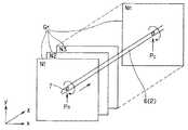
図2はその概略の動作を示す。プローブ挿入部6内の(フレキシブルシャフト8の先端の)超音波振動子7をZ方向に移動しながら回転駆動して超音波をZ軸に直交する方向に放射状に検査対象物側に送波し、検査対象物側の音響インピーダンスの変化部分で反射された反射超音波を受波して超音波振動子7で電気信号に変換され、超音波観測装置3内部で増幅等された後検波され、さらにA/D変換されてデジタルのエコーデータ(音線データ)となり超音波観測装置3内部のメモリ等に一時格納される。
【0019】
この場合、超音波振動子7が1回転するまでに超音波を放射状に送受波する本数を多くする(例えば512本)ことにより、得られる多数の音線データからプローブ挿入部6の軸方向(つまりZ軸方向)にほぼ垂直な断面の2次元超音波画像(以下、ラジアル画像と記す)Grを生成することができる。
【0020】
超音波振動子7は、Z方向にPaからPcの位置まで、所定のピッチ単位でリニア状に移動される。その結果、超音波観測装置3を経て画像処理装置本体4のHDD15には番号N1からNn番目までの、所定のピッチ毎のラジアル画像Grが格納される。
【0021】
得られたラジアル画像Grはメモリ14に転送され、そのメモリ空間には図3の如く格納され、さらにメモリ空間からラジアル画像Grを横から見た(垂直)リニア画像Gvlのデータが読み出され、CPU13は間を補間してフレームメモリ16に転送し、モニタ5にラジアル画像Gr及び対応するリニア画像Gvlを表示することができる。
【0022】
また、図3に示すラジアル画像Grから3次元画像Gsを生成し、例えば図4に示すように、モニタ5の表示部には4つの画像表示エリア(具体的には、ラジアル画像表示エリア、垂直リニア画像表示エリア、水平リニア画像表示エリア、3次元画像表示エリア)にそれぞれラジアル画像Gr、垂直リニア画像Gvl、(右側から見た)水平リニア画像Ghl、3次元画像Gsとを表示する。
【0023】
この場合、ラジアル画像Gr上に設定したカットラインY1、X1をトラックボール21で移動すると、それに対応して垂直リニア画像Gvlと、水平リニア画像Ghlとが更新して表示される。つまり、ラジアル画像Grに表示されたカットラインY1の位置に対応した垂直リニア画像Gvlが表示され、カットラインX1の位置に対応した水平リニア画像Ghlが表示される。
【0024】
また、3次元画像表示エリアにはカットラインY1、X1に対応した切断面M1,M2で3次元画像Gsが表示される。
また、垂直リニア画像Gvl上で、或いは水平リニア画像Ghl上で、カットラインZ1を移動すると、ラジアル画像Gr及び3次元画像Gsの手前側のラジアル画像部分が更新される。
なお、カットラインを移動させる入力手段としてトラックボール21を例示したが、マウス、ジョイスティック、トラックパッド、カーソルキーなどを用いても良い。
【0025】
カットラインY1,X1や切断面M1、M2はユーザの操作で位置を変更することが可能であり、CPU13は変更された位置に対応したラジアル画像Gr、リニア画像Gvl、Ghl、3次元画像Gsを生成する処理を行い、モニタ5にはそれらの画像が表示される。
【0026】
また、本実施の形態では、表示のレイアウトを変更して表示できるようにしている。つまり、図4に示すレイアウトと図5に示すレイアウトを切り替えて(選択して)表示できるようにしており、ユーザは自由に図4のレイアウトと図5のレイアウトを選択できる。
【0027】
図5に示す画像表示のレイアウトは、図4における左側のラジアル画像Grと垂直リニア画像Gvlとの上下の表示位置を入れ替え、さらに右側の水平リニア画像Ghlと3次元画像Gsとの上下の表示位置を入れ替えたレイアウトにしている。なお、図5における3次元画像Gsの表示例では、多重エコー部分を除去して内壁面の状態を分かり易く表示するようにしている。この場合、多重エコーの全部を除去しないで、始点位置での多重エコーを残して表示することにより、リニア走査方向を分かり易くしている。
【0028】
本実施の形態では、以下に説明するように画像処理装置本体4におけるCPU13はリニア移動(実際にはスパイラル状の移動)で得られた複数フレームのラジアル画像Grから生成されるリニア画像の断面波形に対してフーリエ変換を行って、スペクトル分解を行う。
【0029】
その結果、顕著な定常波が検出された場合には、拍動とみなし、拍動周波数とする。そして、その拍動周波数に対応する拍動波長を算出し、その拍動波長(拍動が現れるの)に対応するフレーム枚数を求め、そのフレーム枚数で移動平均を行うことにより、拍動補正された画像を得る。
【0030】
このように本実施の形態では、主にCPU13はZ軸方向に沿った断面線を検出(抽出或いは設定)する断面線検出手段と、その断面線に対応するエコーデータに対して定常波或いは周期性成分を検出する定常波検出手段(或いはスペクトル分解手段)と、検出された場合の定常波の波長を算出する波長算出手段と、算出された波長分で断面線に対応するエコーデータに対して移動平均を行い、この平均化処理されたエコーデータを再構築するエコーデータ再構築手段の機能を持つ。なお、CPU13は断面線の検出からエコーデータ再構築手段までの処理を殆どリアルタイムで行う。
【0031】
また、本実施の形態では、定常波が検出されたか否かを判断することにより、定常波が検出された場合にはその定常波を拍動とみなして、エコーデータを補正し、定常波が検出されない場合には拍動とみなさないでエコーデータを補正しないようにすることにより凹凸がある場合にも適用できるようにしていることも特徴となっている。
【0032】
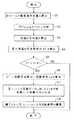
次に本実施の形態による拍動補正の処理により拍動補正したエコーデータ(音線データ)を得て3次元画像を構築する処理を図6のフロ−チャートを参照して以下に説明する。
まず、最初に図2及び図3に示したように超音波プローブ2を駆動して超音波振動子7によりラジアル走査しながら、Z方向に所定のピッチ単位でリニア状に移動し、例えば512本の音線データにより1フレームのラジアル画像Grとなるものを所定の移動範囲まで移動ピッチで除した複数フレームのラジアル画像Grを取得する。そして、この取得された全フレームの音線データ(エコーデータ)に対して以下の拍動補正の処理を行う。
【0033】
まず、最初のステップS1に示すように全フレームについて、補正対象となる壁面(断面)の境界位置、つまり全フレームの壁面境界位置の算出を行う。
次のステップS2で壁面境界位置に対して、リニア断面に沿った音線データの集まりに分け、それらの音線データ波形(波形の各要素は直前の値との差分)を対象として、窓関数、具体的にはハミング窓を用いてFFT(高速フーリエ変換)を行い、周波数成分を算出する、つまりスペクトル分解を行う。なお、この場合、全周、具体的には512本の壁面境界位置の音線データに対して水平方向に対してスペクトル分解を行う。
【0034】
次のステップS3で、全周波数について、全周分の振幅の平均値を算出し、さらにこの平均値を用いてステップS4に示すように最大振幅の周波数成分Afを検出する。
【0035】
図7はスペクトル分解を行った分解結果の波形を実線で示しており、顕著な定常波成分Afが検出されている。これが以下のように拍動周波数Bfとみなされることになる。なお、横軸は周波数、縦軸は振幅を示す。
【0036】
そしてステップS5に示すように、その最大の周波数成分Afが基準値Arefを超えているか否かの比較判断を行い、最大振幅の周波数成分Afが基準値Arefを超えていれば拍動があると判断し、ステップS6に示すようにその最大振幅の周波数成分Afを拍動周波数Bfとする。また、その拍動周波数Bfに対応する拍動波長λaとする(拍動周波数Bfから周期的に拍動が現れる対象枚数とする)。基準値Arefとしては例えば1に近い値を設定する。
【0037】
そして、ステップS7に示すようにこの拍動波長(対象枚数)としてZ方向の各フレームの(補正対象の)音線データに対して移動平均を行い、各フレームの音線データとして補正された音線データが生成される(音線データの再構築が行われる)。
【0038】
このようにして、補正されたフレームの音線データが得られたら、ステップS8に示すように補正されたフレームの音線データにより壁面境界位置の再抽出を行う。またこの拍動補正がされた各フレーム(の音線データ)により壁面境界位置の再抽出を行った後、3次元画像Gsa等を表示する。
一方、ステップS6で最大振幅の周波数成分Afが基準値Arefを超えていない場合には、拍動が無いと判断してこの拍動補正の処理を終了する。この場合には音線データは補正されないので、凹凸を示す音線データを拍動とみなして補正してしまうような処理を行わない。
【0039】
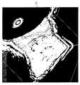
また、図8は補正前の3次元画像Gsを示し、この3次元画像Grは拍動補正により図9に示す補正済み3次元画像Gsaとなる。図8及び図9から分かるように図8の壁面に顕著なギザギザ模様が軽減され、滑らかな断面の画像となる。また、断面の境界のリニア断面線の凹凸もより滑らかに繋がるようになっている。
【0040】
このように本実施の形態によれば、比較的に簡単な処理で拍動補正を行った3次元画像Gsa等を得ることができる。
また、本実施の形態によれば、簡単に拍動補正を行った3次元画像Gsa等を得ることができる。
【0041】
さらに、本実施の形態では、このようにして拍動波長λaを算出できた場合には、新たに超音波プローブ2をリニア移動して3次元画像Gsを構築する場合にはこの拍動波長λaを利用することにより、その拍動補正を行った3次元画像Gsaを構築することもできる。
【0042】
具体的には同じ条件でリニア移動を行った場合には、拍動波長λaの値をそのまま利用することができるし、リニア移動の速度をa倍にした場合にはλa/aをその場合の拍動波長として拍動補正を行うこともできる。
【0043】
このため、本実施の形態による拍動補正の処理は適用できる用途が広く、かつ短時間に拍動補正された3次元画像Gsaを構築することができる。
また、3次元画像Gsaの構築に限らず、リニア断面の2次元断層画像に対しても拍動補正がされた画質の良い超音波画像を提供できる。
【0044】
[付記]
1.検査対象物に対して超音波を所定の移動軸の回りに放射状に送受信しながら前記移動軸の方向に移動することにより得られるエコーデータを用いて3次元超音波画像を構築する3次元超音波画像の構築方法において、
前記移動軸の回りに放射状に送受信した場合に得られる所定本数のエコーデータにより構成される各ラジアル画像における断面等の表示対象となる境界位置を算出する第1の境界算出ステップと、
前記境界位置に対応する全エコーデータに対して前記移動軸と平行なリニア方向のエコーデータの各集まりに分け、各エコーデータの集まりに対して周波数成分に分解する周波数成分算出ステップと、
算出された前記周波数成分に対してしきい値により定常波が存在するか否かを判断する定常波判断ステップと、
定常波が存在すると判断した場合には該定常波が前記ラジアル画像に現れるフレーム枚数で該当するエコーデータの集まり部分に対して移動平均の処理を行うことにより補正されたエコーデータを生成するエコーデータ補正ステップと、
前記補正されたエコーデータにより境界位置を再度算出する第2の境界算出ステップと、
前記第2の境界算出ステップ後の境界位置のエコーデータを用いて3次元超音波画像の構築を行う3次元超音波画像の構築方法。
【0045】
【発明の効果】
以上説明したように本発明によれば、定常波の検出の有無により、拍動か否かを判別して、拍動の影響を補正した超音波画像を得ることができる。
特に体腔内で得られた超音波画像に適用すると、拍動の影響を受けない良好な超音波画像を得ることができる。
【図面の簡単な説明】
【図1】本発明の第1の実施の形態を備えた超音波診断装置の全体構成を示すブロック図。
【図2】図2の動作からラジアル画像等が得られる様子を示す図。
【図3】4つの表示エリアに2次元画像と3次元画像を同時に表示した表示例を示す図。
【図4】4つの表示エリアに2次元画像と3次元画像を同時に表示した表示例を示す図。
【図5】図4とは異なるレイアウトでの2次元画像と3次元画像を同時に表示した表示例を示す図。
【図6】拍動補正の処理内容を示すフローチャート図。
【図7】図6のステップS2によるスペクトル分解を行った場合の波形例を示す図。
【図8】拍動補正を行う前の3次元画像の表示例を示す図。
【図9】拍動補正を行った後の3次元画像の表示例を示す図。
【符号の説明】
1…超音波診断装置
2…超音波プローブ
3…超音波観測装置
4…画像処理装置本体
5…モニタ
6…プローブ挿入部
7…超音波振動子
8…フレキシブルシャフト
9…駆動部
13…CPU
14…メモリ
15…HDD
16…フレームメモリ
17…DVD−RAM
18…MOD
19…SCSII/F
21…トラックボール
22…キーボード
25…MO[0001]
TECHNICAL FIELD OF THE INVENTION
The present invention relates to an ultrasonic image processing apparatus that transmits and receives ultrasonic waves to and from an inspection target such as a living body and displays an ultrasonic image.
[0002]
[Prior art]
2. Description of the Related Art In recent years, in the medical field and the industrial field, an ultrasonic diagnostic apparatus for non-invasively diagnosing the inside of a test object by transmitting and receiving ultrasonic waves to and from the test object has been widely used.
[0003]
In this case, since the image obtained by the ultrasonic scanning is a two-dimensional image, the ultrasonic image processing is performed to construct a three-dimensional image from the two-dimensional image and to provide an image that can be more easily diagnosed for the user. May be used in combination with equipment.
[0004]
In this case, in order to construct a three-dimensional image from a two-dimensional image, the ultrasonic transducer is generally driven in a spiral manner, but is affected by pulsation by a living body.
[0005]
For this reason, for example, in Japanese Patent Application Laid-Open No. 2000-316864, a distortion amount of image data is detected in order to remove the influence of the pulsation, and the detected distortion amount is corrected by an image correction unit, so that an image having a high image quality can be obtained. An ultrasonic tomographic image is obtained.
[0006]
[Patent Document 1]
JP 2000-316864 A
[Problems to be solved by the invention]
In the above conventional example, since the image distortion amount of each of the plurality of tomographic images is detected and the image distortion amount is corrected, it is difficult to discriminate between the case due to the pulsation and the case where the unevenness actually exists.
[0008]
(Object of the invention)
The present invention has been made in view of the above points, and has as its object to provide an ultrasonic image processing apparatus capable of easily identifying the presence or absence of a beat and obtaining an ultrasound image in which the influence of the beat is corrected. And
[0009]
[Means for Solving the Problems]
In an ultrasonic image processing apparatus that transmits and receives ultrasonic waves to scan a three-dimensional area with respect to an inspection object and displays an ultrasonic image of the inspection object using the obtained echo data of the three-dimensional area,
A cross section line detecting means for detecting a cross section line along at least one direction axis over an appropriate length;
A standing wave detection unit that detects a standing wave generated in the section line,
A wavelength calculating means for calculating the wavelength of the detected standing wave, and a moving average of the received echo data based on the calculated wavelength, and an echo data reconstructing means for reconstructing,
Is provided, so that the echo data reconstructed by the echo data reconstructing means removes the influence of the pulsation due to the standing wave so that an ultrasonic image can be obtained.
[0010]
BEST MODE FOR CARRYING OUT THE INVENTION
Hereinafter, embodiments of the present invention will be described with reference to the drawings.
1 to 9 relate to an embodiment of the present invention. FIG. 1 shows an overall configuration of an ultrasonic diagnostic apparatus provided with the embodiment, and FIG. 2 is a diagram for obtaining a two-dimensional image and a three-dimensional image. FIG. 3 shows a state in which a radial image or the like is obtained from the operation in FIG. 2, and FIG. 4 shows a display example in which a two-dimensional image and a three-dimensional image are simultaneously displayed in four display areas. 5 shows a display example in which a two-dimensional image and a three-dimensional image in a layout different from that of FIG. 4 are simultaneously displayed, FIG. 6 shows the processing contents for constructing a three-dimensional image by pulsation correction processing, and FIG. FIG. 8 shows a waveform example when spectral decomposition is performed in step S2, FIG. 8 shows a display example of a three-dimensional image before pulsation correction is performed, and FIG. 9 is a table of a three-dimensional image after pulsation correction is performed. An example is shown.
[0011]
As shown in FIG. 1, an ultrasonic diagnostic apparatus 1 according to an embodiment of the present invention includes an
[0012]
The
[0013]
Further, a
[0014]
The image processing apparatus main body 4 connected to the
[0015]
Note that the DVD-
Note that the image processing apparatus main body 4, the
In the present embodiment, the program is stored in, for example, a magneto-optical disk (abbreviated as MO) 25 that is attached to and detached from the
[0016]
Instead of the
[0017]
Since the first motor and the second motor are provided in the
[0018]
FIG. 2 shows the schematic operation. The ultrasonic transducer 7 (at the tip of the flexible shaft 8) in the
[0019]
In this case, by increasing the number of ultrasonic waves transmitted and received radially until the
[0020]
The
[0021]
The obtained radial image Gr is transferred to the
[0022]
Further, a three-dimensional image Gs is generated from the radial image Gr shown in FIG. 3, and for example, as shown in FIG. 4, the display unit of the
[0023]
In this case, when the cut lines Y1 and X1 set on the radial image Gr are moved by the
[0024]
Further, in the three-dimensional image display area, a three-dimensional image Gs is displayed on cut planes M1 and M2 corresponding to the cut lines Y1 and X1.
Further, when the cut line Z1 is moved on the vertical linear image Gvl or on the horizontal linear image Ghl, the radial image portion on the front side of the radial image Gr and the three-dimensional image Gs is updated.
Although the
[0025]
The positions of the cut lines Y1 and X1 and the cut planes M1 and M2 can be changed by a user's operation, and the
[0026]
Further, in the present embodiment, the display layout can be changed and displayed. That is, the layout shown in FIG. 4 and the layout shown in FIG. 5 can be switched (selected) and displayed, and the user can freely select the layout of FIG. 4 and the layout of FIG.
[0027]
The image display layout shown in FIG. 5 is such that the upper and lower display positions of the left radial image Gr and the vertical linear image Gvl in FIG. 4 are exchanged, and the upper and lower display positions of the right horizontal linear image Ghl and the three-dimensional image Gs are further changed. The layout is changed. In the display example of the three-dimensional image Gs in FIG. 5, the state of the inner wall surface is displayed in an easily understandable manner by removing a multiple echo portion. In this case, the linear scanning direction can be easily understood by displaying the multiple echoes at the start position without removing the entire multiple echoes.
[0028]
In the present embodiment, as described below, the
[0029]
As a result, when a remarkable standing wave is detected, it is regarded as a pulsation and the pulsation frequency is set. Then, the pulsation wavelength corresponding to the pulsation frequency is calculated, the number of frames corresponding to the pulsation wavelength (where the pulsation appears) is obtained, and a moving average is performed using the number of frames to correct the pulsation. Image.
[0030]
As described above, in the present embodiment, the
[0031]
Further, in the present embodiment, by determining whether or not a standing wave is detected, when the standing wave is detected, the standing wave is regarded as a pulsation, the echo data is corrected, and when the standing wave is not detected. Is characterized in that echo data is not corrected without being regarded as a pulsation so that it can be applied even when there is unevenness.
[0032]
Next, a process of constructing a three-dimensional image by obtaining echo data (sound ray data) subjected to pulsation correction by the pulsation correction process according to the present embodiment will be described below with reference to the flowchart of FIG.
First, as shown in FIGS. 2 and 3, the
[0033]
First, as shown in the first step S1, a boundary position of a wall surface (cross section) to be corrected, that is, a wall boundary position of all frames is calculated for all frames.
In the next step S2, for the wall surface boundary position, the sound ray data is divided into a group of sound ray data along the linear section, and the sound ray data waveform (each element of the waveform is a difference from the immediately preceding value) is used as a window function. Specifically, FFT (Fast Fourier Transform) is performed using a Hamming window to calculate frequency components, that is, to perform spectral decomposition. In this case, spectral decomposition is performed on the entire circumference, specifically, the sound ray data at 512 wall boundary positions in the horizontal direction.
[0034]
In the next step S3, an average value of the amplitudes of all the circumferences is calculated for all the frequencies, and the average value is used to detect the frequency component Af of the maximum amplitude as shown in step S4.
[0035]
FIG. 7 shows the waveform of the decomposition result obtained by performing the spectral decomposition with a solid line, and a remarkable standing wave component Af is detected. This is regarded as the pulsation frequency Bf as follows. The horizontal axis represents frequency, and the vertical axis represents amplitude.
[0036]
Then, as shown in step S5, it is determined whether or not the maximum frequency component Af exceeds the reference value Aref. If the maximum amplitude frequency component Af exceeds the reference value Aref, it is determined that there is a pulsation. Judgment is made, and the frequency component Af of the maximum amplitude is set as the pulsation frequency Bf as shown in step S6. In addition, the pulsation wavelength λa corresponding to the pulsation frequency Bf is set (the number of pulsations periodically appearing from the pulsation frequency Bf). For example, a value close to 1 is set as the reference value Aref.
[0037]
Then, as shown in step S7, a moving average is performed on the sound ray data (to be corrected) of each frame in the Z direction as the pulsation wavelength (number of target), and the sound corrected as the sound ray data of each frame is performed. Line data is generated (sound ray data is reconstructed).
[0038]
When the sound ray data of the corrected frame is obtained in this way, the wall boundary position is re-extracted using the sound ray data of the corrected frame as shown in step S8. After the wall boundary position is re-extracted from each of the beat-corrected frames (sound ray data), a three-dimensional image Gsa or the like is displayed.
On the other hand, if the frequency component Af having the maximum amplitude does not exceed the reference value Aref in step S6, it is determined that there is no pulsation, and the pulsation correction processing is terminated. In this case, since the sound ray data is not corrected, a process of correcting the sound ray data indicating irregularities as a beat is not performed.
[0039]
FIG. 8 shows a three-dimensional image Gs before correction, and this three-dimensional image Gr becomes a corrected three-dimensional image Gsa shown in FIG. 9 by pulsation correction. As can be seen from FIGS. 8 and 9, a noticeable jagged pattern on the wall surface in FIG. 8 is reduced, and an image having a smooth cross section is obtained. Also, the unevenness of the linear section line at the boundary of the section is connected more smoothly.
[0040]
As described above, according to the present embodiment, it is possible to obtain a three-dimensional image Gsa or the like on which pulsation correction has been performed by relatively simple processing.
Further, according to the present embodiment, it is possible to easily obtain a three-dimensional image Gsa or the like on which pulsation correction has been performed.
[0041]
Furthermore, in the present embodiment, when the pulsation wavelength λa can be calculated in this way, when the
[0042]
Specifically, when the linear movement is performed under the same conditions, the value of the pulsation wavelength λa can be used as it is, and when the speed of the linear movement is multiplied by a, λa / a is Pulsation correction can also be performed as the pulsation wavelength.
[0043]
Therefore, the pulsation correction processing according to the present embodiment can be applied to a wide range of applications, and a pulsation-corrected three-dimensional image Gsa can be constructed in a short time.
In addition to the construction of the three-dimensional image Gsa, it is possible to provide a high-quality ultrasonic image in which pulsation correction has been performed on a two-dimensional tomographic image having a linear cross section.
[0044]
[Appendix]
1. Three-dimensional ultrasound which constructs a three-dimensional ultrasound image using echo data obtained by moving in the direction of the moving axis while transmitting and receiving ultrasonic waves radially around a predetermined moving axis with respect to the inspection object In the image construction method,
A first boundary calculation step of calculating a boundary position to be displayed, such as a cross section in each radial image formed by a predetermined number of echo data obtained when transmission and reception are performed radially around the movement axis;
A frequency component calculation step of dividing each set of echo data in a linear direction parallel to the movement axis for all echo data corresponding to the boundary position, and decomposing each set of echo data into frequency components,
A standing wave determination step of determining whether a standing wave exists by a threshold value for the calculated frequency component,
When it is determined that a standing wave exists, an echo data correcting step of generating a corrected echo data by performing a moving average process on a collection portion of the echo data corresponding to the number of frames in which the standing wave appears in the radial image When,
A second boundary calculation step of calculating a boundary position again based on the corrected echo data;
A method for constructing a three-dimensional ultrasonic image, wherein a three-dimensional ultrasonic image is constructed using echo data at a boundary position after the second boundary calculation step.
[0045]
【The invention's effect】
As described above, according to the present invention, it is possible to determine whether or not a pulsation has occurred based on whether or not a standing wave has been detected, and obtain an ultrasonic image in which the influence of the pulsation has been corrected.
Particularly when applied to an ultrasonic image obtained in a body cavity, a favorable ultrasonic image which is not affected by pulsation can be obtained.
[Brief description of the drawings]
FIG. 1 is a block diagram showing an overall configuration of an ultrasonic diagnostic apparatus having a first embodiment of the present invention.
FIG. 2 is a diagram showing how a radial image or the like is obtained from the operation of FIG. 2;
FIG. 3 is a diagram showing a display example in which a two-dimensional image and a three-dimensional image are simultaneously displayed on four display areas.
FIG. 4 is a view showing a display example in which a two-dimensional image and a three-dimensional image are simultaneously displayed on four display areas.
FIG. 5 is a view showing a display example in which a two-dimensional image and a three-dimensional image in a layout different from that in FIG. 4 are simultaneously displayed.
FIG. 6 is a flowchart showing the processing content of beat correction.
FIG. 7 is a view showing an example of a waveform when spectrum decomposition is performed in step S2 of FIG. 6;
FIG. 8 is a diagram showing a display example of a three-dimensional image before performing pulsation correction.
FIG. 9 is a diagram showing a display example of a three-dimensional image after pulsation correction has been performed.
[Explanation of symbols]
DESCRIPTION OF SYMBOLS 1 ... Ultrasonic
14 ...
16
18… MOD
19 ... SCSII / F
21: Trackball 22: Keyboard 25: MO
Claims (3)
Translated fromJapanese少なくとも1つの方向軸に沿う断面線を適宜長に亘って検出する断面線検出手段と、
前記断面線に生じる定常波を検出する定常波検出手段と、
前記検出された定常波の波長を算出する波長算出手段と、および
前記算出された波長に基づいて前記受信したエコーデータを移動平均すると共に、再構築するエコーデータ再構築手段と、
を備えることを特徴とする超音波画像処理装置。In an ultrasonic image processing apparatus that transmits and receives ultrasonic waves to scan a three-dimensional area with respect to an inspection object and displays an ultrasonic image of the inspection object using the obtained echo data of the three-dimensional area,
A cross section line detecting means for detecting a cross section line along at least one direction axis over an appropriate length;
A standing wave detection unit that detects a standing wave generated in the section line,
A wavelength calculating means for calculating the wavelength of the detected standing wave, and a moving average of the received echo data based on the calculated wavelength, and an echo data reconstructing means for reconstructing,
An ultrasonic image processing apparatus comprising:
Priority Applications (1)
| Application Number | Priority Date | Filing Date | Title |
|---|---|---|---|
| JP2003139514AJP4262517B2 (en) | 2003-05-16 | 2003-05-16 | Ultrasonic image processing device |
Applications Claiming Priority (1)
| Application Number | Priority Date | Filing Date | Title |
|---|---|---|---|
| JP2003139514AJP4262517B2 (en) | 2003-05-16 | 2003-05-16 | Ultrasonic image processing device |
Publications (2)
| Publication Number | Publication Date |
|---|---|
| JP2004337457Atrue JP2004337457A (en) | 2004-12-02 |
| JP4262517B2 JP4262517B2 (en) | 2009-05-13 |
Family
ID=33528572
Family Applications (1)
| Application Number | Title | Priority Date | Filing Date |
|---|---|---|---|
| JP2003139514AExpired - Fee RelatedJP4262517B2 (en) | 2003-05-16 | 2003-05-16 | Ultrasonic image processing device |
Country Status (1)
| Country | Link |
|---|---|
| JP (1) | JP4262517B2 (en) |
Cited By (22)
| Publication number | Priority date | Publication date | Assignee | Title |
|---|---|---|---|---|
| JP2009508552A (en)* | 2005-09-15 | 2009-03-05 | インナー ビジョン メディカル テクノロジーズ インコーポレイテッド | Determining attributes using ultrasound |
| US8234923B2 (en) | 2004-09-20 | 2012-08-07 | Innervision Medical Technologies Inc. | Systems and methods for ultrasound imaging |
| US9072495B2 (en) | 2006-10-25 | 2015-07-07 | Maui Imaging, Inc. | Method and apparatus to produce ultrasonic images using multiple apertures |
| US9146313B2 (en) | 2006-09-14 | 2015-09-29 | Maui Imaging, Inc. | Point source transmission and speed-of-sound correction using multi-aperature ultrasound imaging |
| US9192355B2 (en) | 2006-02-06 | 2015-11-24 | Maui Imaging, Inc. | Multiple aperture ultrasound array alignment fixture |
| US9220478B2 (en) | 2010-04-14 | 2015-12-29 | Maui Imaging, Inc. | Concave ultrasound transducers and 3D arrays |
| US9265484B2 (en) | 2011-12-29 | 2016-02-23 | Maui Imaging, Inc. | M-mode ultrasound imaging of arbitrary paths |
| US9282945B2 (en) | 2009-04-14 | 2016-03-15 | Maui Imaging, Inc. | Calibration of ultrasound probes |
| US9339256B2 (en) | 2007-10-01 | 2016-05-17 | Maui Imaging, Inc. | Determining material stiffness using multiple aperture ultrasound |
| US9510806B2 (en) | 2013-03-13 | 2016-12-06 | Maui Imaging, Inc. | Alignment of ultrasound transducer arrays and multiple aperture probe assembly |
| US9572549B2 (en) | 2012-08-10 | 2017-02-21 | Maui Imaging, Inc. | Calibration of multiple aperture ultrasound probes |
| US9582876B2 (en) | 2006-02-06 | 2017-02-28 | Maui Imaging, Inc. | Method and apparatus to visualize the coronary arteries using ultrasound |
| US9668714B2 (en) | 2010-04-14 | 2017-06-06 | Maui Imaging, Inc. | Systems and methods for improving ultrasound image quality by applying weighting factors |
| US9788813B2 (en) | 2010-10-13 | 2017-10-17 | Maui Imaging, Inc. | Multiple aperture probe internal apparatus and cable assemblies |
| US9883848B2 (en) | 2013-09-13 | 2018-02-06 | Maui Imaging, Inc. | Ultrasound imaging using apparent point-source transmit transducer |
| US9986969B2 (en) | 2012-09-06 | 2018-06-05 | Maui Imaging, Inc. | Ultrasound imaging system memory architecture |
| CN108135578A (en)* | 2015-09-29 | 2018-06-08 | 古野电气株式会社 | Ultrasonic wave tissue detection device, ultrasonic wave tissue detection method and ultrasonic wave tissue detection program |
| US10226234B2 (en) | 2011-12-01 | 2019-03-12 | Maui Imaging, Inc. | Motion detection using ping-based and multiple aperture doppler ultrasound |
| US10401493B2 (en) | 2014-08-18 | 2019-09-03 | Maui Imaging, Inc. | Network-based ultrasound imaging system |
| US10856846B2 (en) | 2016-01-27 | 2020-12-08 | Maui Imaging, Inc. | Ultrasound imaging with sparse array probes |
| US12167209B2 (en) | 2012-09-06 | 2024-12-10 | Maui Imaging, Inc. | Ultrasound imaging system memory architecture |
| US12190627B2 (en) | 2015-03-30 | 2025-01-07 | Maui Imaging, Inc. | Ultrasound imaging systems and methods for detecting object motion |
- 2003
- 2003-05-16JPJP2003139514Apatent/JP4262517B2/ennot_activeExpired - Fee Related
Cited By (46)
| Publication number | Priority date | Publication date | Assignee | Title |
|---|---|---|---|---|
| US8234923B2 (en) | 2004-09-20 | 2012-08-07 | Innervision Medical Technologies Inc. | Systems and methods for ultrasound imaging |
| US9188673B2 (en) | 2004-09-20 | 2015-11-17 | Innervision Medical Technologies Inc. | Systems and methods for ultrasound imaging |
| JP2009508552A (en)* | 2005-09-15 | 2009-03-05 | インナー ビジョン メディカル テクノロジーズ インコーポレイテッド | Determining attributes using ultrasound |
| US9192355B2 (en) | 2006-02-06 | 2015-11-24 | Maui Imaging, Inc. | Multiple aperture ultrasound array alignment fixture |
| US9582876B2 (en) | 2006-02-06 | 2017-02-28 | Maui Imaging, Inc. | Method and apparatus to visualize the coronary arteries using ultrasound |
| US9146313B2 (en) | 2006-09-14 | 2015-09-29 | Maui Imaging, Inc. | Point source transmission and speed-of-sound correction using multi-aperature ultrasound imaging |
| US9526475B2 (en) | 2006-09-14 | 2016-12-27 | Maui Imaging, Inc. | Point source transmission and speed-of-sound correction using multi-aperture ultrasound imaging |
| US9986975B2 (en) | 2006-09-14 | 2018-06-05 | Maui Imaging, Inc. | Point source transmission and speed-of-sound correction using multi-aperture ultrasound imaging |
| US10130333B2 (en) | 2006-10-25 | 2018-11-20 | Maui Imaging, Inc. | Method and apparatus to produce ultrasonic images using multiple apertures |
| US9420994B2 (en) | 2006-10-25 | 2016-08-23 | Maui Imaging, Inc. | Method and apparatus to produce ultrasonic images using multiple apertures |
| US9072495B2 (en) | 2006-10-25 | 2015-07-07 | Maui Imaging, Inc. | Method and apparatus to produce ultrasonic images using multiple apertures |
| US10675000B2 (en) | 2007-10-01 | 2020-06-09 | Maui Imaging, Inc. | Determining material stiffness using multiple aperture ultrasound |
| US9339256B2 (en) | 2007-10-01 | 2016-05-17 | Maui Imaging, Inc. | Determining material stiffness using multiple aperture ultrasound |
| US11051791B2 (en)* | 2009-04-14 | 2021-07-06 | Maui Imaging, Inc. | Calibration of ultrasound probes |
| US9282945B2 (en) | 2009-04-14 | 2016-03-15 | Maui Imaging, Inc. | Calibration of ultrasound probes |
| US10206662B2 (en) | 2009-04-14 | 2019-02-19 | Maui Imaging, Inc. | Calibration of ultrasound probes |
| US11998395B2 (en) | 2010-02-18 | 2024-06-04 | Maui Imaging, Inc. | Point source transmission and speed-of-sound correction using multi-aperture ultrasound imaging |
| US9668714B2 (en) | 2010-04-14 | 2017-06-06 | Maui Imaging, Inc. | Systems and methods for improving ultrasound image quality by applying weighting factors |
| US10835208B2 (en) | 2010-04-14 | 2020-11-17 | Maui Imaging, Inc. | Concave ultrasound transducers and 3D arrays |
| US9220478B2 (en) | 2010-04-14 | 2015-12-29 | Maui Imaging, Inc. | Concave ultrasound transducers and 3D arrays |
| US11172911B2 (en) | 2010-04-14 | 2021-11-16 | Maui Imaging, Inc. | Systems and methods for improving ultrasound image quality by applying weighting factors |
| US9247926B2 (en) | 2010-04-14 | 2016-02-02 | Maui Imaging, Inc. | Concave ultrasound transducers and 3D arrays |
| US12350101B2 (en) | 2010-10-13 | 2025-07-08 | Maui Imaging, Inc. | Concave ultrasound transducers and 3D arrays |
| US9788813B2 (en) | 2010-10-13 | 2017-10-17 | Maui Imaging, Inc. | Multiple aperture probe internal apparatus and cable assemblies |
| US10226234B2 (en) | 2011-12-01 | 2019-03-12 | Maui Imaging, Inc. | Motion detection using ping-based and multiple aperture doppler ultrasound |
| US9265484B2 (en) | 2011-12-29 | 2016-02-23 | Maui Imaging, Inc. | M-mode ultrasound imaging of arbitrary paths |
| US10617384B2 (en) | 2011-12-29 | 2020-04-14 | Maui Imaging, Inc. | M-mode ultrasound imaging of arbitrary paths |
| US12343210B2 (en) | 2012-02-21 | 2025-07-01 | Maui Imaging, Inc. | Determining material stiffness using multiple aperture ultrasound |
| US12186133B2 (en) | 2012-03-26 | 2025-01-07 | Maui Imaging, Inc. | Systems and methods for improving ultrasound image quality by applying weighting factors |
| US10064605B2 (en) | 2012-08-10 | 2018-09-04 | Maui Imaging, Inc. | Calibration of multiple aperture ultrasound probes |
| US9572549B2 (en) | 2012-08-10 | 2017-02-21 | Maui Imaging, Inc. | Calibration of multiple aperture ultrasound probes |
| US12171621B2 (en) | 2012-08-10 | 2024-12-24 | Maui Imaging, Inc. | Calibration of multiple aperture ultrasound probes |
| US11253233B2 (en) | 2012-08-10 | 2022-02-22 | Maui Imaging, Inc. | Calibration of multiple aperture ultrasound probes |
| US12167209B2 (en) | 2012-09-06 | 2024-12-10 | Maui Imaging, Inc. | Ultrasound imaging system memory architecture |
| US9986969B2 (en) | 2012-09-06 | 2018-06-05 | Maui Imaging, Inc. | Ultrasound imaging system memory architecture |
| US10267913B2 (en) | 2013-03-13 | 2019-04-23 | Maui Imaging, Inc. | Alignment of ultrasound transducer arrays and multiple aperture probe assembly |
| US9510806B2 (en) | 2013-03-13 | 2016-12-06 | Maui Imaging, Inc. | Alignment of ultrasound transducer arrays and multiple aperture probe assembly |
| US10653392B2 (en) | 2013-09-13 | 2020-05-19 | Maui Imaging, Inc. | Ultrasound imaging using apparent point-source transmit transducer |
| US9883848B2 (en) | 2013-09-13 | 2018-02-06 | Maui Imaging, Inc. | Ultrasound imaging using apparent point-source transmit transducer |
| US12426855B2 (en) | 2013-09-13 | 2025-09-30 | Maui Imaging, Inc. | Ultrasound imaging using apparent point-source transmit transducer |
| US10401493B2 (en) | 2014-08-18 | 2019-09-03 | Maui Imaging, Inc. | Network-based ultrasound imaging system |
| US12204023B2 (en) | 2014-08-18 | 2025-01-21 | Maui Imaging, Inc. | Network-based ultrasound imaging system |
| US12190627B2 (en) | 2015-03-30 | 2025-01-07 | Maui Imaging, Inc. | Ultrasound imaging systems and methods for detecting object motion |
| CN108135578A (en)* | 2015-09-29 | 2018-06-08 | 古野电气株式会社 | Ultrasonic wave tissue detection device, ultrasonic wave tissue detection method and ultrasonic wave tissue detection program |
| US10856846B2 (en) | 2016-01-27 | 2020-12-08 | Maui Imaging, Inc. | Ultrasound imaging with sparse array probes |
| US12048587B2 (en) | 2016-01-27 | 2024-07-30 | Maui Imaging, Inc. | Ultrasound imaging with sparse array probes |
Also Published As
| Publication number | Publication date |
|---|---|
| JP4262517B2 (en) | 2009-05-13 |
Similar Documents
| Publication | Publication Date | Title |
|---|---|---|
| JP4262517B2 (en) | Ultrasonic image processing device | |
| JP6635766B2 (en) | Ultrasound diagnostic apparatus, signal processing apparatus, and analysis program | |
| JP5393232B2 (en) | Three-dimensional image construction apparatus and operation method thereof | |
| JP5840181B2 (en) | Photoacoustic image generation apparatus and method | |
| JPH04317641A (en) | Ultrasonic imaging device | |
| JP5683860B2 (en) | Ultrasonic diagnostic apparatus, ultrasonic image processing apparatus, ultrasonic diagnostic apparatus control program, and ultrasonic image processing program | |
| JPH10127638A (en) | Signal processing method for object including moving part, and echo graphic device executing the method | |
| JP6073563B2 (en) | Ultrasonic diagnostic apparatus, image processing apparatus, and image processing program | |
| JP4245976B2 (en) | Ultrasonic image processing device | |
| JPH11327A (en) | Ultrasound diagnostic equipment | |
| JP6513230B2 (en) | Ultrasonic observation apparatus, method of operating ultrasonic observation apparatus, and operation program of ultrasonic observation apparatus | |
| CN111093519B (en) | Ultrasound image processing | |
| JP4468677B2 (en) | Ultrasonic image generation method and ultrasonic image generation program | |
| US20070016047A1 (en) | Apparatus for and method of processing ultrasonic signal | |
| WO2012090658A1 (en) | Ultrasonic diagnosis device and image processing method | |
| JP2024048667A (en) | ULTRASONIC DIAGNOSTIC APPARATUS AND METHOD FOR CONTROLLING ULTRASONIC DIAGNOSTIC APPARATUS | |
| JP2010504834A (en) | System and method for repairing medical images affected by non-uniform rotational distortion | |
| JP2006167450A (en) | Method of selecting part of run of echocardiography image | |
| JP4109155B2 (en) | Ultrasonic image processing device | |
| JP7185708B2 (en) | Puncture needle, ultrasonic diagnostic device, and control method for ultrasonic diagnostic device | |
| US12433565B2 (en) | Ultrasound diagnostic apparatus and control method of ultrasound diagnostic apparatus | |
| JP7102553B2 (en) | Control method of puncture needle, ultrasonic diagnostic device and ultrasonic diagnostic device | |
| JP5032094B2 (en) | Ultrasonic diagnostic apparatus and control program | |
| JP3905419B2 (en) | Ultrasonic image processing device | |
| JP2002306481A (en) | Ultrasonic image processor |
Legal Events
| Date | Code | Title | Description |
|---|---|---|---|
| A621 | Written request for application examination | Free format text:JAPANESE INTERMEDIATE CODE: A621 Effective date:20060323 | |
| A977 | Report on retrieval | Free format text:JAPANESE INTERMEDIATE CODE: A971007 Effective date:20090115 | |
| TRDD | Decision of grant or rejection written | ||
| A01 | Written decision to grant a patent or to grant a registration (utility model) | Free format text:JAPANESE INTERMEDIATE CODE: A01 Effective date:20090120 | |
| A01 | Written decision to grant a patent or to grant a registration (utility model) | Free format text:JAPANESE INTERMEDIATE CODE: A01 | |
| A61 | First payment of annual fees (during grant procedure) | Free format text:JAPANESE INTERMEDIATE CODE: A61 Effective date:20090209 | |
| FPAY | Renewal fee payment (event date is renewal date of database) | Free format text:PAYMENT UNTIL: 20120220 Year of fee payment:3 | |
| R151 | Written notification of patent or utility model registration | Ref document number:4262517 Country of ref document:JP Free format text:JAPANESE INTERMEDIATE CODE: R151 | |
| FPAY | Renewal fee payment (event date is renewal date of database) | Free format text:PAYMENT UNTIL: 20120220 Year of fee payment:3 | |
| FPAY | Renewal fee payment (event date is renewal date of database) | Free format text:PAYMENT UNTIL: 20120220 Year of fee payment:3 | |
| FPAY | Renewal fee payment (event date is renewal date of database) | Free format text:PAYMENT UNTIL: 20130220 Year of fee payment:4 | |
| FPAY | Renewal fee payment (event date is renewal date of database) | Free format text:PAYMENT UNTIL: 20140220 Year of fee payment:5 | |
| S531 | Written request for registration of change of domicile | Free format text:JAPANESE INTERMEDIATE CODE: R313531 | |
| R350 | Written notification of registration of transfer | Free format text:JAPANESE INTERMEDIATE CODE: R350 | |
| R250 | Receipt of annual fees | Free format text:JAPANESE INTERMEDIATE CODE: R250 | |
| R250 | Receipt of annual fees | Free format text:JAPANESE INTERMEDIATE CODE: R250 | |
| LAPS | Cancellation because of no payment of annual fees |