JP2004336453A - Copying machine, image processing system, program and storage medium - Google Patents
Copying machine, image processing system, program and storage mediumDownload PDFInfo
- Publication number
- JP2004336453A JP2004336453AJP2003130283AJP2003130283AJP2004336453AJP 2004336453 AJP2004336453 AJP 2004336453AJP 2003130283 AJP2003130283 AJP 2003130283AJP 2003130283 AJP2003130283 AJP 2003130283AJP 2004336453 AJP2004336453 AJP 2004336453A
- Authority
- JP
- Japan
- Prior art keywords
- format
- image data
- data
- image
- copying machine
- Prior art date
- Legal status (The legal status is an assumption and is not a legal conclusion. Google has not performed a legal analysis and makes no representation as to the accuracy of the status listed.)
- Pending
Links
Images


Classifications
- H—ELECTRICITY
- H04—ELECTRIC COMMUNICATION TECHNIQUE
- H04N—PICTORIAL COMMUNICATION, e.g. TELEVISION
- H04N19/00—Methods or arrangements for coding, decoding, compressing or decompressing digital video signals
- H04N19/85—Methods or arrangements for coding, decoding, compressing or decompressing digital video signals using pre-processing or post-processing specially adapted for video compression
- H—ELECTRICITY
- H04—ELECTRIC COMMUNICATION TECHNIQUE
- H04N—PICTORIAL COMMUNICATION, e.g. TELEVISION
- H04N1/00—Scanning, transmission or reproduction of documents or the like, e.g. facsimile transmission; Details thereof
- H04N1/00127—Connection or combination of a still picture apparatus with another apparatus, e.g. for storage, processing or transmission of still picture signals or of information associated with a still picture
- H04N1/00204—Connection or combination of a still picture apparatus with another apparatus, e.g. for storage, processing or transmission of still picture signals or of information associated with a still picture with a digital computer or a digital computer system, e.g. an internet server
- H04N1/00209—Transmitting or receiving image data, e.g. facsimile data, via a computer, e.g. using e-mail, a computer network, the internet, I-fax
- H—ELECTRICITY
- H04—ELECTRIC COMMUNICATION TECHNIQUE
- H04N—PICTORIAL COMMUNICATION, e.g. TELEVISION
- H04N1/00—Scanning, transmission or reproduction of documents or the like, e.g. facsimile transmission; Details thereof
- H04N1/00127—Connection or combination of a still picture apparatus with another apparatus, e.g. for storage, processing or transmission of still picture signals or of information associated with a still picture
- H04N1/00204—Connection or combination of a still picture apparatus with another apparatus, e.g. for storage, processing or transmission of still picture signals or of information associated with a still picture with a digital computer or a digital computer system, e.g. an internet server
- H04N1/00236—Connection or combination of a still picture apparatus with another apparatus, e.g. for storage, processing or transmission of still picture signals or of information associated with a still picture with a digital computer or a digital computer system, e.g. an internet server using an image reading or reproducing device, e.g. a facsimile reader or printer, as a local input to or local output from a computer
- H04N1/00241—Connection or combination of a still picture apparatus with another apparatus, e.g. for storage, processing or transmission of still picture signals or of information associated with a still picture with a digital computer or a digital computer system, e.g. an internet server using an image reading or reproducing device, e.g. a facsimile reader or printer, as a local input to or local output from a computer using an image reading device as a local input to a computer
- H—ELECTRICITY
- H04—ELECTRIC COMMUNICATION TECHNIQUE
- H04N—PICTORIAL COMMUNICATION, e.g. TELEVISION
- H04N2201/00—Indexing scheme relating to scanning, transmission or reproduction of documents or the like, and to details thereof
- H04N2201/0077—Types of the still picture apparatus
- H04N2201/0081—Image reader
- H—ELECTRICITY
- H04—ELECTRIC COMMUNICATION TECHNIQUE
- H04N—PICTORIAL COMMUNICATION, e.g. TELEVISION
- H04N2201/00—Indexing scheme relating to scanning, transmission or reproduction of documents or the like, and to details thereof
- H04N2201/0077—Types of the still picture apparatus
- H04N2201/0082—Image hardcopy reproducer
- H—ELECTRICITY
- H04—ELECTRIC COMMUNICATION TECHNIQUE
- H04N—PICTORIAL COMMUNICATION, e.g. TELEVISION
- H04N2201/00—Indexing scheme relating to scanning, transmission or reproduction of documents or the like, and to details thereof
- H04N2201/0077—Types of the still picture apparatus
- H04N2201/0086—Image transceiver
- H—ELECTRICITY
- H04—ELECTRIC COMMUNICATION TECHNIQUE
- H04N—PICTORIAL COMMUNICATION, e.g. TELEVISION
- H04N2201/00—Indexing scheme relating to scanning, transmission or reproduction of documents or the like, and to details thereof
- H04N2201/0077—Types of the still picture apparatus
- H04N2201/0091—Digital copier; digital 'photocopier'
- H—ELECTRICITY
- H04—ELECTRIC COMMUNICATION TECHNIQUE
- H04N—PICTORIAL COMMUNICATION, e.g. TELEVISION
- H04N2201/00—Indexing scheme relating to scanning, transmission or reproduction of documents or the like, and to details thereof
- H04N2201/0077—Types of the still picture apparatus
- H04N2201/0094—Multifunctional device, i.e. a device capable of all of reading, reproducing, copying, facsimile transception, file transception
Landscapes
- Engineering & Computer Science (AREA)
- General Engineering & Computer Science (AREA)
- Multimedia (AREA)
- Signal Processing (AREA)
- Computing Systems (AREA)
- Facsimiles In General (AREA)
- Accessory Devices And Overall Control Thereof (AREA)
- Facsimile Image Signal Circuits (AREA)
- Color Image Communication Systems (AREA)
- Image Processing (AREA)
Abstract
Translated fromJapaneseDescription
Translated fromJapanese【0001】
【発明の属する技術分野】
この発明は、複写機、画像処理システム、プログラム及び記憶媒体に関する。
【0002】
【従来の技術】
ネットワークにデジタル複写機や画像読取装置を接続し、このデジタル複写機や画像読取装置のスキャナで原稿画像をスキャンして、読み取った画像データをネットワークに接続されたコンピュータ等の端末に配信する、ネットワークスキャナという機能が知られている。
【0003】
例えば、特許文献1には、汎用コンピュータシステムのアーキテクチャをベースにした拡張ボックスを有し、画像形成装置の画像入力部において、スキャンした画像を拡張ボックス内のハードディスク装置(スキャンボックス)に蓄積し、スキャンボックス内の画像ファイルをネットワークに接続された各コンピュータシステム間で共有することが提案されている。
【0004】
このスキャナボックス機能を用いる処理手順は以下のようなものである。まず、解像度、階調、倍率、読み込み面、画像サイズ、保存先などのスキャンパラメータを選択し、画像原稿を読み込む。そして、読み込んだ画像データを画像処理部に転送して、スキャンパラメータに従った画像処理を実行する。但し、画像の印刷出力は予定していないので、印刷出力系のデータフォーマットを生成する必要はなく、RGB系からCMYK系への色座標系変換や階調補正、画像データの圧縮処理は省略される。そして、画像処理後の画像データは拡張ボックスに転送される。拡張ボックスでは、ハードディスク装置内の所定ディスク領域に割り当てられたスキャンボックスに受信した画像データを一時保存し、全ての原稿ページを蓄積し終えると、ネットワークのクライアントがスキャンボックスから画像データを取り出す。
【0005】
【特許文献1】
特開2000−333026公報
【0006】
【発明が解決しようとする課題】
しかしながら、特許文献1に開示の技術においては、印刷のための画像処理が施された画像データと、スキャンボックスの配信用の画像処理が施された画像データとでは画像処理が異なるため、同じデジタル複写機で印刷出力した画像データと、ネットワークスキャナで配信した画像データを、同じデジタル複写機を用いてプリントアウトした場合に印刷画像が異なるという不具合があった。
【0007】
また、クライアントとなるパソコンなどで、操作部から解像度、階調、倍率、読み込み面、画像サイズ、保存先などのスキャンパラメータを選択した場合、原稿をスキャンし、読み込まれた画像データは画像処理部へ転送し、スキャンパラメータに従った画像処理を実行した後にハードディスクに蓄積されるため、蓄積後の画像データに対して画像フォーマットの変換ができないため、記憶媒体に蓄積されている画像データを複数の人が異なる画像フォーマット条件で受け取りたい場合は、各クライアントの要求条件にあわせてスキャンしなおさなければならないという不具合もあった。
【0008】
さらに、ハードディスクに蓄積されている画像データはデジタル複写機で取り扱う専用のフォーマットである場合が多く、また、メモリ容量の節約のために圧縮アルゴリズムで圧縮する際に専用のアルゴリズムで圧縮されることがあることから、パソコンに配信しても汎用のアプリケーションで画像を見、あるいは編集することができないという不具合もあった。
【0009】
本発明の目的は、外部に画像データを送信可能な複写機等において、複写機等における画像データにもとづく場合でも、クライアントPCなどで受信した画像データにもとづく場合でも、複写機等で画像形成した画像を同様の画質にすることができるようにすることである。
【0010】
また、記憶装置に記憶済みの画像データに対してデータ形式を変換するので、同一画像データにつき複数の人が異なるデータ形式で画像データを受け取ることができるようにすることである。
【0011】
【課題を解決するための手段】
請求項1に記載の発明は、原稿の画像を読み取る画像読取装置と、この読み取った原稿の画像データに基づいて媒体上に画像の形成を行うプリンタエンジンと、を備えている複写機において、前記画像データについてそのデータ形式を所定の第1の形式で記憶装置に記憶する記憶手段と、所定の送信先への前記画像データの送信の要求を受け付ける受付手段と、この記憶している画像データのデータ形式を前記第1の形式から所定の第2の形式に変換するデータ形式変換手段と、前記受付があったときは前記変換後の画像データを前記所定の送信先に送信する送信手段と、を備えていることを特徴とする複写機である。
【0012】
したがって、複写機は記憶装置に記憶されている画像データを、外部のクライアントPCなどからの要求によりデータ形式の変換を行って、外部のクライアントPCなどで扱える形式に変換して出力することで、複写機の画像データを外部のクライアントPCなどでも利用することができる。また、複写機における画像データにもとづく場合でも、クライアントPCなどで受信した画像データにもとづく場合でも、複写機で画像形成した画像を同様の画質にすることができる。さらに、記憶装置に記憶済みの画像データに対してデータ形式を変換するので、同一画像データにつき複数の人が異なるデータ形式で画像データを受け取ることができる。
【0013】
請求項2に記載の発明は、請求項1に記載の複写機において、前記受付手段は、前記第2の形式の指定も受け付けるものであり、前記データ形式変換手段は、前記変換後の画像データを前記指定された第2の形式とする、ことを特徴とする。
【0014】
したがって、外部のクライアントPCなどから要求されたとおりのデータ形式に変換して送信するので、送信先の需要に応じた形式の画像データを提供することができる。
【0015】
請求項3に記載の発明は、請求項1又は2に記載の複写機において、前記データ形式変換手段は、前記第2の形式と前記第1の形式とでデータフォーマットを変えるものである、ことを特徴とする。
【0016】
したがって、複写機におけるデータフォーマットを外部のクライアントPCなどでも利用できるものに変えることができる。
【0017】
請求項4に記載の発明は、請求項3に記載の複写機において、前記第1の形式、前記第2の形式とも汎用のデータフォーマットを用いている、ことを特徴とする。
【0018】
したがって、複写機における汎用のデータフォーマットを外部のクライアントPCなどでも利用できる他の汎用のデータフォーマットに変えることができる。
【0019】
請求項5に記載の発明は、請求項3に記載の複写機において、前記第1の形式は本装置に専用の、前記第2の形式は汎用のデータフォーマットを用いている、ことを特徴とする。
【0020】
したがって、複写機における専用のデータフォーマットを外部のクライアントPCなどでも利用できる他の汎用のデータフォーマットに変えることができる。
【0021】
請求項6に記載の発明は、請求項3に記載の複写機において、前記第1の形式、前記第2の形式とも本装置に専用のデータフォーマットを用いている、ことを特徴とする。
【0022】
したがって、複写機における専用のデータフォーマットを外部のクライアントPCなどでも利用できる他の専用のデータフォーマットに変えることができる。
【0023】
請求項7に記載の発明は、請求項2〜6のいずれかの一に記載の複写機において、前記データ形式変換手段は、前記第1の形式と前記第2の形式とで画像データの色空間を変える、ことを特徴とする。
【0024】
したがって、複写機における画像データがプリンタエンジンによる画像形成に適した色空間のものなどであっても、外部のクライアントPCなどでディスプレイ表示するのに適する色空間などに変換することができる。
【0025】
請求項8に記載の発明は、請求項7に記載の複写機において、前記データ形式変換手段は、前記第2の形式の色空間をデバイスインディペンデントな色空間としている、ことを特徴とする。
【0026】
したがって、複写機における画像データがデバイスディペンデンスな色空間であっても、デバイスインディペンデントな色空間に変換して、外部のクライアントPCなどで利用しやすくすることができる。
【0027】
請求項9に記載の発明は、請求項2〜6のいずれかの一に記載の複写機において、前記データ形式変換手段は、前記第1の形式が所定の色空間の画像データであるときに前記第2の形式をモノクロの2値又は多値画像データとしている、ことを特徴とする。
【0028】
したがって、複写機における画像データが所定の色空間のものであっても、モノクロの2値又は多値画像データに変換して、モノクロの2値又は多値画像データとして利用したい外部のクライアントPCなどの需要を満足することができる。
【0029】
請求項10に記載の発明は、請求項9に記載の複写機において、前記データ形式変換手段は、前記第2の形式をモノクロの2値画像データであるときに前記第1の形式の画像データをモノクロの多値画像データに変換してから前記第2の形式への変換を行う、ことを特徴とする。
【0030】
したがって、複写機における画像データをモノクロの多値画像データに変換してからモノクロの2値画像データに変換するので、モノクロの2値画像データに変換する前にさまざまな画像処理を行って、外部のクライアントPCなどの需要を満足することができる。
【0031】
請求項11に記載の発明は、請求項2〜6のいずれかの一に記載の複写機において、前記データ形式変換手段は、前記第1の形式がモノクロの2値又は多値画像データであるときに前記第2の形式をモノクロの2値又は多値画像データとしている、ことを特徴とする。
【0032】
したがって、複写機におけるモノクロの2値又は多値画像データ画像データであっても、所定の形式のモノクロの2値又は多値画像データに変換して送信し、かかる形式のモノクロの2値又は多値画像データとして利用したい外部のクライアントPCなどの需要を満足することができる。
【0033】
請求項12に記載の発明は、請求項10に記載の複写機において、前記データ形式変換手段は、前記第1の形式の画像データを多値画像データに変換してから前記第2の形式への変換を行う、ことを特徴とする。
【0034】
したがって、複写機における画像データをモノクロの多値画像データに変換してからモノクロの2値画像データに変換するので、モノクロの2値画像データに変換する前にさまざまな画像処理を行って送信し、外部のクライアントPCなどの需要を満足することができる。
【0035】
請求項13に記載の発明は、請求項2〜12のいずれかの一に記載の複写機において、前記データ形式変換手段は、前記第2の形式の画像データを前記第1の形式と異なる解像度とする、ことを特徴とする。
【0036】
したがって、複写機における画像データを所定の解像度に変換して送信し、外部のクライアントPCなどの需要を満足することができる。
【0037】
請求項14に記載の発明は、請求項2〜10,12のいずれかの一に記載の複写機において、前記データ形式変換手段は、前記第1の形式の画像データに空間フィルタ処理を行う、ことを特徴とする。
【0038】
したがって、複写機における画像データを空間フィルタ処理して送信し、外部のクライアントPCなどの需要を満足することができる。
【0039】
請求項15に記載の発明は、請求項2〜10,12のいずれかの一に記載の複写機において、前記データ形式変換手段は、前記第1の形式の画像データにγ変換を行う、ことを特徴とする。
【0040】
したがって、複写機における画像データをγ変換して送信し、外部のクライアントPCなどの需要を満足することができる。
【0041】
請求項16に記載の発明は、請求項2〜10,12のいずれかの一に記載の複写機において、前記データ形式変換手段は、前記第1の形式の画像データに孤立点の除去の処理を行う、ことを特徴とする。
【0042】
したがって、複写機における画像データに孤立点の除去の処理を行って送信し、外部のクライアントPCなどの需要を満足することができる。
【0043】
請求項17に記載の発明は、画像データに基づいて所定の処理を行う画像処理システムにおいて、前記画像データについてそのデータ形式を所定の第1の形式で記憶装置に記憶する記憶手段と、外部から前記画像データの送信の要求を受け付ける受付手段と、この記憶している画像データのデータ形式を前記第1の形式から所定の第2の形式に変換するデータ形式変換手段と、前記受付があったときは前記変換後の画像データを所定の送信先に送信する送信手段と、を備えていることを特徴とする画像処理システムである。
【0044】
したがって、画像処理システムは記憶装置に記憶されている画像データを、外部のクライアントPCなどからの要求によりデータ形式の変換を行って、外部のクライアントPCなどで扱える形式に変換して出力することで、画像処理システムの画像データを外部のクライアントPCなどでも利用することができる。また、記憶装置に記憶済みの画像データに対してデータ形式を変換するので、同一画像データにつき複数の人が異なるデータ形式で画像データを受け取ることができる。
【0045】
請求項18に記載の発明は、原稿の画像を読み取る画像読取装置と、この読み取った原稿の画像データに基づいて媒体上に画像の形成を行うプリンタエンジンと、を備えている複写機を制御するコンピュータに読み取り可能なプログラムにおいて、前記画像データについてそのデータ形式を所定の第1の形式で記憶装置に記憶する記憶処理と、外部から前記画像データの送信の要求を受け付ける受付処理と、この記憶している画像データのデータ形式を前記第1の形式から所定の第2の形式に変換する第1のデータ形式変換処理と、前記受付があったときは前記変換後の画像データを所定の送信先に送信する送信処理と、を複写機に実行させることを特徴とするプログラムである。
【0046】
したがって、複写機は記憶装置に記憶されている画像データを、外部のクライアントPCなどからの要求によりデータ形式の変換を行って、外部のクライアントPCなどで扱える形式に変換して出力することで、複写機の画像データを外部のクライアントPCなどでも利用することができる。また、複写機における画像データにもとづく場合でも、クライアントPCなどで受信した画像データにもとづく場合でも、複写機で画像形成した画像を同様の画質にすることができる。さらに、記憶装置に記憶済みの画像データに対してデータ形式を変換するので、同一画像データにつき複数の人が異なるデータ形式で画像データを受け取ることができる。
【0047】
請求項19に記載の発明は、請求項18に記載のプログラムにおいて、前記受付処理は、前記第2の形式の指定も受け付けるものであり、前記データ形式変換処理は、前記変換後の画像データを前記指定された第2の形式とする、ことを特徴とする。
【0048】
したがって、外部のクライアントPCなどから要求されたとおりのデータ形式に変換して送信するので、送信先の需要に応じた形式の画像データを提供することができる。
【0049】
請求項20に記載の発明は、請求項18又は19に記載のプログラムを記憶している記憶媒体である。
【0050】
したがって、記憶しているプログラムにより請求項18又は19に記載の発明と同様の作用、効果を奏することができる。
【0051】
【発明の実施の形態】
本発明の一実施の形態について説明する。
【0052】
図1は、本実施の形態のデジタル複写機1の構成を説明するブロック図である。このデジタル複写機1は、本発明の複写機、画像処理システムを実施するものであり、いわゆる複合機である。以下では、図1を参照して、デジタル複写機1の各部の概略構成及び原稿を複写する際に原稿の画像を読み取って印刷出力するまでの一連の処理の内容について説明する。なお、画像データの流れを図1中に矢印で示している。
【0053】
ここに説明するデジタル複写機1の機能は、エンジン部2とプリンタコントローラ部3とに大別される。デジタル複写機1は、本発明の画像処理システムを実施するものであるので、画像データに基づいて後述するような所定の処理を行う。
【0054】
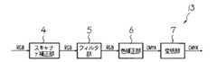
まず、エンジン部2の全体は、エンジンコントローラ20により制御される。このエンジン部2において、読み取りユニット12は、原稿の画像を読み取る画像読取装置であり、原稿の画像はR,G,Bに色分解された画像データとして読み取られ、スキャナ補正部13に送られる。図2に示すように、スキャナ補正部13では、R,G,Bの画像データに対して、スキャナγ補正部4でスキャナγ処理、フィルタ処理部5でフィルタ処理、色補正処理部6でCMYKの色信号に変換する色補正処理、変倍処理部7で変倍処理が、それぞれ行われる。
【0055】
図1に示すように、スキャナ補正部13で処理後のCMYK各色8bitの色データは、固定長の圧縮器8によって各色nbit(n≦8)の色データに変換される。この圧縮後の画像データ汎用バスI/F9を介してプリンタコントローラ10に送られる。
【0056】
メインコントローラ26の制御により、プリンタコントローラ10は、画像データの色毎に独立した記憶装置である半導体メモリ10b(メモリC,M,Y,K)を備えていて、送られた画像データを蓄積する(記憶手段、記憶処理)。また、ハードディスク11には、この蓄積されたデータが随時記憶される(記憶手段、記憶処理)。これは、本装置によるプリントアウト時に用紙がつまり、印字が正常に終了しなかった場合でも、再び原稿を読み直すのを避けるためであり、また、電子ソートを行うためである。近年はこれだけでなく、読み取った原稿を蓄積しておき、必要なときに再出力する機能が追加されている。
【0057】
画像データを出力する場合は、記憶装置であるハードディスク11内の画像データは一度プリンタコントローラ10の半導体メモリに展開され、次に汎用バス9を介してエンジン部2に送られる。そして、エンジン部2の固定長の伸張器14は、この画像データを再びCMYKの8bitの画像データに変換する。この変換後の画像データは、プリンタ補正部15に送られる。
【0058】
図3に示すように、プリンタ補正部15では、CMYKの各色の画像データに対してプリンタγ補正部16でプリンタγ補正を行う。次に、作像ユニット19にあわせた中間調処理を中間調処理部17で行い、プリンタエンジンとなる作像ユニット19により転写紙などの媒体に画像を形成して出力する。作像ユニット19の印刷方式は、電子写真方式のほか、インクジェット方式、昇華型熱転写方式、銀塩写真方式、直接感熱記録方式、溶融型熱転写方式など、さまざまな方式を用いることができる。
【0059】
図1に示すように、FAXコントローラ21は、デジタル複写機1のFAX機能を制御し、電話回線などの所定のネットワークとの間で画像データの送受信を行う。圧縮・伸張器21aは、送受信する画像データの圧縮、伸張を行う。ネットワークインターフェースコントーラ(NIC)22は、デジタル複写機1をLANなどのネットワークに接続するためのインターフェイスである。データ形式変換装置24の詳細については後述する。メインコントローラ26は、マイクロコンピュータを備え、デジタル複写機1の全体を集中的に制御する。
【0060】
図4に示すように、ハードディスク11に蓄積された画像データは、一度プリンタコントローラ10の半導体メモリ10bに展開され、次に汎用バス9を介してデータ形式変換装置24に送られる。データ形式変換装置24は、画像データに所望の画像処理を施して、NIC22を介して外部のPC25などに配信する。この場合に、PC25などに配信する画像データは、圧縮符号のままでもよいし、圧縮・伸張器10aで伸張してから配信するようにしてもよい。
【0061】
なお、ここまでの説明では、CMYK系の色空間で圧縮された画像データがハードディスク11に蓄積される場合について説明をしたが、ハードディスク11に蓄積される画像データは、デジタル複写機1で複写画像として読み取られたある色空間系の画像データである。ここで、ある色空間とは、デバイスディペンデンスな(デバイスの種類に依存した)色空間(RGB,Yuv,CMYKなど)であってもよいし、デバイスインディペンデント(デバイスの種類に依存しない)な色空間(sRGBなど)であってもよい。
【0062】
次に、データ形式変換装置24の構成について説明する。図5は、データ形式変換装置24の構成を示すブロック図である。図5に示すように、入力ポート31は、ハードディスク11に蓄積されていた画像データを、汎用バス9を介して受け付ける。伸張器32は、圧縮されている当該画像データを伸張する。この伸張後の画像データは、解像度変換器33で所定の解像度に解像度変換され、色空間変換器34により所定の色空間に変換され、圧縮器35により所定の圧縮符号化形式で圧縮符号化され、出力ポート36により汎用バス9出力され、外部のPC25などに送信される。これにより、ハードディスク11に蓄積されていた第1の形式の画像データは、そのデータ形式が変更されて第2の形式の画像データとして出力される。
【0063】
次に、データ形式変換装置24のより具体的な構成例について説明する。
【0064】
まず、図6の例は、データ形式変換装置24に入力される画像データが多値データであり、この入力多値データは多値データ圧縮方式によってデータ圧縮された汎用のデータフォーマットである。そして、データ形式変換装置24が出力する画像データは多値データであり、この出力多値データは多値圧縮方式によって圧縮された汎用のデータフォーマットである。すなわち、伸張器32、圧縮器35は、汎用のデータフォーマットで伸張、圧縮を行う。なお、図6において、画像処理部37は、前述の解像度変換器33、色空間変換器34などを備えている。また、入力ポート31、出力ポート36については、図示を省略している(これらについては、後述の図7、図8においても同様)。
【0065】
この例では、汎用のデータフォーマットとしてJPEGを用いているが、そのほかにもJPEG2000など、PCなどで一般的に使用できる汎用のデータフォーマットを用いることができる。
【0066】
このように、JPEGのような標準化されている汎用のデータフォーマットでデータの送受信を行うことで、送受信されるユニット間でのデータフォーマットを統一することができる。さらに、データ品質と、データ送受信効率の双方を維持したデータ形式変換システムが構築可能となる。
【0067】
また、画像データが2値データである場合は、MHMR/MMR方式等の汎用の標準的な画像の圧縮、伸張フォーマットを用いることができる。
【0068】
図7の例では、データ形式変換装置24に入力する画像データがデジタル複写機1の専用のデータフォーマットで圧縮されていて、出力する画像データは図6の例と同様な汎用のデータフォーマットとしている。ここでいう専用のデータフォーマットとは、デジタル複写機1に特有のデータフォーマットであって、JPEG、JPEG2000など、通常のPCなどで普通に用いることができる汎用のデータフォーマットではないことである。
【0069】
そのため、伸張器32においては、専用のデータフォーマットからの伸張方式として、圧縮効率、もしくは、データ加工効率を維持した専用のブロック固定長伸張方式を用いている。圧縮器35における圧縮方式は、図6の例と同様に汎用のデータフォーマットを用いる。
【0070】
図7の例においては、このように専用のデータフォーマットが専用的なブロック固定長圧縮データであるため、特に画像データによる圧縮率の変動を固定化して管理することができる。さらに、ブロック単位で取り扱うことで、画像の向きの回転、並び替え等のデータ加工が容易となる。なお、ブロック固定長符号化、復号の方式は公知であるため、詳細な説明は省略する(必要であれば、特開平11−331844号公報を参照)。画像データが2値データの場合には、例えば、特開2002−077627公報に開示の技術を用いることができる。
【0071】
また、JPEGの様な、標準化されている汎用のデータフォーマットで画像データの送信を行うことで、送信されるユニットでのデータフォーマットを統一でき、さらに、データ品質と、データ送受信効率の双方を維持したデータ形式変換システムが構築可能となる。
【0072】
なお、画像データが2値データである場合は、圧縮器35において、MHMR/MMR方式等の汎用の標準的な画像の圧縮、伸張フォーマットを用いることができる。
【0073】
図8の例では、図7の例と異なり、データ形式変換装置24から出力する画像データも、データ形式変換装置24に入力されたものと同じデジタル複写機1の専用のデータフォーマットで圧縮されている。そのため、圧縮器35においては、この専用のデータフォーマットでブロック固定長圧縮により画像データを圧縮する。
【0074】
このように、専用のデータフォーマットが専用的なブロック固定長圧縮データであることで、特に画像データによる圧縮率の変動を固定化して管理することができる。さらに、画像データをブロック単位で取り扱うことで、画像の向きの回転、並び替え等のデータ加工が容易となる。ブロック固定長符号化、復号の方式は公知であるため、詳細な説明は省略する(必要であれば、特開平11−331844号公報を参照)。また、画像データが2値データの場合には、例えば、特開2002−077627公報に開示の技術を用いることができる。
【0075】
次に、解像度変換器33について説明する。
【0076】
この例では、対象となる画素データが多値データであり、主走査方向と副走査方向の双方に任意の解像度への変換が可能な方式の例を説明する。図9(a)に示すように、この解像度変換器33は、入力される多値データに対して主走査方向に解像度変換を行う主走査解像度変換ブロック41と、主走査方向に変換後の多値データに対して副走査方向に解像度変換する副走査解像度変換ブロック42とで構成されている。
【0077】
図9(b)に示すように、主走査解像度変換ブロック41では、入力多値データを指定された解像度へのデータ数の変換をするために、主走査方向に画素補間を行う。補間する画素データ値の算出方式としては、一般的な最近接画素置換法、隣接2画素加重平均法、3次関数コンボリューション法などを用いることを想定している。具体的には、各1ビットのデータをラッチできる複数のフリップフロップ43で画素データを記憶し、補間画素算出部44で補間するデータ値の算出を行う。
【0078】
図9(c)に示すように、主走査方向への解像度変換後のデータは、副走査解像度変換ブロック42で、主走査解像度変換後の1ライン分のデータを蓄積可能なラインメモリ45を複数ライン分もった副走査ライン蓄積メモリ46から、副走査方向の参照画素データに基づいて、補間するラインのデータ値の算出を補間画素算出部47で行う。算出方式は、主走査方向と同様に最近接画素置換法、隣接2画素加重平均法、3次関数コンボリューション法などを用いることができる。
【0079】
次に、色空間変換器34による色空間変換機能について説明する。
【0080】
以下では、色空間変換の一例としてテーブル補間法によって色空間変換を行う例について説明する。
【0081】
かかる処理では、所定のルックアップテーブル(LUT)を用いる。ここでは、xyz方向の各軸を8分割し(図10(a)参照)、入力色空間を上位と下位にわけて上位でLUTを参照し、下位で3次元補間を行って精密な出力を得る。
【0082】
3次元補間法には多数種類があるが、ここでは線形補間の中でも最も簡単な四面体補間法を例にあげる。四面体補間法は、図10(a)に示すように、入力色空間を複数の単位立方体に分割して、さらに単位立方体の対称軸を共有する6個の四面体に分割する(図10(b))。これにより入力色信号は、入力色信号の上位座標により選択された単位四面体(図10(c))の分割境界点(格子点)のパラメータ(以下格子点パラメータという)をLUTより参照する。次に下位座標により選択された単位四面体の格子点パラメータから線形演算することで出力値を得ることができる。
【0083】
実際の処理手順は以下の通りである。
【0084】
1.入力色信号X(x,y,z)を内包する単位立方体を選択する。
【0085】
2.選択された単位立方体内での座標Pの下位座標(lx,lly,llz)を求める。
【0086】
3.下位座標の大小比較により単位四面体を選択して単位四面体毎に線形補間をおこない、座標Pでの出力値Poutを求める。各単位四面体の線形補間の演算式は下式で表される(なお、ここで“l”の記号は、単位立方体の一辺の長さを示す)。
【0087】
(lx<ly<lz)Pout=P2+(P5−P7)×lx/l+(P7−P8)×ly/l+(P8−P2)×lz/l
(ly≦lx<lz)Pout=P2+(P6−P8)×lx/l+(P5−P6)×ly/l+(P8−P2)×lz/l
(ly<lz≦lx)Pout=P2+(P4−P2)×lx/l+(P5−P6)×ly/l+(P6−P4)×lz/l
(lz≦ly≦lx)Pout=P2+(P4−P2)×lx/l+(P3−P4)×ly/l+(P5−P3)×lz/l
(lz≦lx<ly)Pout=P2+(P3−P1)×lx/l+(P1−P2)×ly/l+(P5−P3)×lz/l
(lx<lz≦ly)Pout=P2+(P5−P7)×lx/l+(P1−P1)×ly/l+(P7−P1)×lz/l
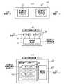
次に、具体的にPC25などに画像データを出力する場合の処理について説明する。図11に示すように、クライアントとなる各PC25は、デジタル複写機1から画像データを受け取る(キャプチャする)際の属性を決定し、この属性を提示してデジタル複写機1に画像データを要求する。このPC25からの画像キャプチャ要求信号とハードディスク11に蓄積されている画像データの属性から、データ形式変換装置24内の画像データパラメータ値が決定する。
【0088】
このパラメータ値により、図5に示すデータ形式変換装置24の伸張器32、解像度変換器33、色空間変換器34、圧縮器35のパラメータが変更され、データ形式変換装置24で画像処理が施された画像データを、要求先のPC25へ配信する。
【0089】
前述のように、ハードディスク11に蓄積される画像データは、デジタル複写機1で複写画像として読み取られたある色空間系の画像データである。
【0090】
ここで、例えば、ハードディスク11に蓄積されている画像データを非圧縮で、解像度が600dpiである、CMYK系の画像データとする。図11の各クライアントとなるPC25において、
クライアントAは解像度200dpi sRGB空間の JPEG画像
クライアントBは解像度400dpi Yuv空間の TIFF画像
クライアントCは解像度100dpi Lab空間の JPEG2000画像
という画像データの属性で画像データを受け取る(キャプチャする)ことをPC25から要求する。
【0091】
メインコントローラ26は、データ形式変換装置24により、それぞれの要求をうけて各PC25の要求に応じた画像処理を画像データに対して施す。
【0092】
この例では、ハードディスク11に蓄積されている画像データは非圧縮であるので伸張器32はスルー動作である。そして、次の解像度変換器33では、クライアントの解像度の要求とハードディスクに蓄積されている画像データの解像度からデータ形式変換装置24内の解像度変換器33の解像度変換パラメータ値が決定する。この例では、クライアントAに対しては600dpiから200dpiへの解像度変換が、クライアントBに対しては600dpiから400dpiへの解像度変換が、クライアントCに対しては600dpiから100dpiへの解像度変換が施される。
【0093】
次に色空間変換器34では、クライアントAに対してはCMYKからsRGB空間への色空間変換処理が、クライアントBに対してはCMYKからYuvへ色空間変換処理が、クライアントCに対してはCMYKからLabへの色空間変換処理が施される。
【0094】
そして、圧縮器35では、クライアントAに対してはJPEGファイル形式への変換が、クライアントBに対してはTIFFファイル形式への変換が、クライアントCに対してはJPEG2000ファイル形式への変換処理が施される。
【0095】
また、ハードディスク11に蓄積される画像データは、デジタル複写機1で複写画像として読み取られたある色空間系の画像データであるが、ハードディスク11には画像データと一緒にPC25が画像データの属性を指定して画像データを読み取った際の画像データの属性と、そのPC25の識別情報とを一緒に蓄積するようにしてもよい。
【0096】
これにより、クライアントはPC25により画像を受け取る(キャプチャする)際に、キャプチャする属性を指定せずにハードディスク11に蓄積されている画像データの属性をそのまま受け継ぎたい場合は、PC25からキャプチャする画像データの属性を設定するという手間が省くことができ操作性がよい。
【0097】
次に、データ形式変換装置24の他の構成例について説明する。
【0098】
前述の例では、ハードディスク11などに記憶しているある色空間の画像データを他の色空間の画像データに変換してPC25などに出力する場合を基本的に想定しているが、次の例は、ハードディスク11などに記憶しているカラー多値画像データをモノクロ2値画像データに変換してPC25などに出力する例である。
【0099】
図12は、データ形式変換装置24の他の構成例を示すブロック図である。なお、前述の入力ポート31、出力ポート36に相当するブロックは図示を省略する(以下同様)。ハードディスク11などに記憶されている画像データは、所定の色空間の画像、この例ではCMYKの版ごとに固定長の多値圧縮の方式でデータ圧縮が行われている画像であるものとする。伸張器51は、この圧縮符号である画像データの伸張を行なう。解像度変換器52は、所定の変倍率により画像データの解像度変換を行なう。CMYK→RGB変換器53は、画像データについてCMYKの色空間から所定のRGBの色空間への変換を行なう。RGB→Gray変換器54は、カラー多値画像データをモノクロ多値画像データに変換する。孤立点除去部55は、モノクロ多値画像データに対して孤立点の検出アルゴリズムにより孤立点の検出を行なう。フィルタ56は、PC25により指定されたモードで強調や平滑の処理を行なう。濃度γ部57は、画像の濃度の調整を行なう。2値化処理部58は、所定の方式によって画像データの2値化を行う。圧縮器58は、MHMR/MMR方式等の汎用のデータ圧縮方式でデータ圧縮を行う。
【0100】
データ形式変換装置24をこのような構成とすることにより、カラー複写の画像データをモノクロの2値画像データに変換してPC25などに取り込みたいという場合にも対応できる。すなわち、カラーの画像データはPC25側に取り込んだときに容量が大きく負荷が大きいので、モノクロの2値画像に変換して取り込みたいという場合がある。この例では、このような要求に答えることが可能になる。
【0101】
次に、図12のブロックの詳細について説明する。
【0102】
まず、CMYK→RGB変換器53の色変換については図10などを参照して前述したとおりである。
【0103】
フィルタ56の処理について説明する。フィルタ処理は、画像データのMTFを変調させるものであるが、もとの画像データよりもMTF値を高めて画像のエッジを強調する場合と、MTF値を下げて画像を平滑化する場合の2種類がある。
【0104】
画像データのMTFを高める場合は、基画像の画像周波数を実線、フィルタ処理後の画像周波数を破線で示すと、図13(a)に示しているように、画像周波数の隆起を強調するような処理を施す。但し、縦軸は画像濃度のダイナミックレンジとし、横軸は画像データのラスタ形式参照を示している。
【0105】
同様に、画像データのMTFを平滑化する場合は、図13(b)に示しているように、画像周波数の隆起が鈍るような処理を施す。実際の処理としては、2次元の画像データのラスタ形式方向をライン方向(x方向)、他方向をy方向とし、画像データをライン単位で扱い、注目画素値を周辺の画素値を基に算出する。
【0106】
図13(c)は、注目画素を中心とした周辺5×5画素を、注目画素をXn,mとして、周辺画素を記号化して表している。
【0107】
画像データのMTFを高める場合は、強調する必要がある画像周波数の微分係数を、画像データの解像度を基調としてマトリクス状に配置した係数(以下、マトリクス係数という)を算出する。そのマトリクス係数を、周辺画素記号と同形式に、Am−2,n−2,Am−2,n−1,…,Am,n,Am+2,n+1,Am+2,n+2と記号化すると、画像データのMTFを高める場合のフィルタ処理後の注目画素値Yは、次のような演算式で表せる。
【0108】
【0109】
画像データを平滑化する場合は、注目画素とその周辺画素を加算して画素数Eで除算することにより、注目画素とその周辺画素との平均値を求める。このような演算により、画像データの全画素を変換することで、画像データの平滑化の操作を行う。平滑化の度合いを調整する意味で、注目画素や周辺画素の重みを単純に等価として平均化せず、各画素間に隔たりを持たせるのであれば、下記(4)式のようにマトリクス係数に任意の整数を代入することで、注目画素値Yを調整することが可能である。
【0110】
【0111】
次に、濃度γ部57が行う処理について説明する。
【0112】
γ変換処理は、画像の濃度勾配や濃度特性を可変とするものである。図14に示すように、図14(a)の実線がγ変換テーブルとすると、グラフに従って、もとの画像データ(横軸)に相当する値をγ変換後の画像データ(縦軸)の値に変換するだけである。この変換テーブルの曲線を変更して、狙いの濃度分布をもつ画像データに変更することが可能となる。例えば、図14(a)の破線で示しているようなγ変換テーブルにすれば、実線で示しているγ変換テーブルに比べ、γ変換後の画像データを濃度勾配が滑らかな画像データに変換することができる。但し、図14(a)において、図の矢印側になるにつれ濃度が高くなる。
【0113】
γ変換テーブルの作成方法は、便宜上、図14(b)に示してある原点から45°方向に延びるリニアなγ変換テーブル(実線)を、もとに説明する。
【0114】
濃度特性を変えずに画像の全体濃度を上下させる場合は、図14(b)に示すように、グラフの横軸方向にγ変換テーブル(破線)のように平行移動させればよく、画像の濃度勾配を変える場合は、γ変換テーブルの傾きを変更すればよい。また、濃度特性を変更する場合は、図14(a)にあるような、連続する曲線で示せるようなγ変換テーブルの湾曲具合を変更すれば、任意の濃度特性が得られる。
【0115】
これらの手段により、濃度γ部57では、多値の画像データに対し、画像データの濃度勾配及び濃度特性の変更を可能とするγ変換処理機能を実現できる。このことにより、画像の種類に応じたγカーブを選択することで高品質な画像の取得が可能となる。
【0116】
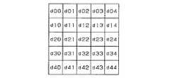
孤立点除去部55の処理について説明する。フィルタ56により画像に強調フィルタがかけられると、原画像に含まれているノイズも強調されてしまうので、ごみが多くなり、見苦しい画像となってしまう場合がある。このような場合、孤立点除去部55の処理により孤立点の除去が適応的に行われる。孤立点除去のアルゴリズムには様々な方式を用いることができるが、図15に示すようなマトリクスを用いた方法をここでは説明する。
【0117】
孤立点除去部55では、図15に示すような5×5ブロックで孤立点の判定が行われる。この例で注目画素はd22である。注目画素以外の画素が全て所定の閾値TH1より小さければ、注目画素を白画素(画素値0)に置き換える。
【0118】
このような処理を行うことにより、読取ユニット12で読み取った画像中のごみ画像を除去することができる。
【0119】
ハードディスク11に格納されている画像データが自然画像を読み取ったものであるばあいには孤立点除去は効果的である。一方、自然画像ではなく、プリンタRIPデータのように電子的に作られたものである場合には行う必要はない。
【0120】
そこで、PC25側に転送する画像の種類によって、適宜、孤立点除去の動作パラメータを切り替えるようにすれば、高品質な画像を得ることができる。
【0121】
次に、2値化処理部58が実行する処理について説明する。
【0122】
2値化処理部58は、多値画像データに対し、中間調処理を行って2値化する。中間調処理は、多値画像データを2値若しくはそれに近い少値の階調数に量子化する処理であるが、その具体的方法は様々存在する。ここでは、一般的に用いられる、単純量子化法、ディザ法、誤差拡散法について説明する。但し、量子化階調数は、便宜上2値とする。
【0123】
まず、単純量子化法は、多値の画像データのダイナミックレンジ中の任意の値を閾値として、画像データを2階調化するものである。例えば、ダイナミックレンジが0〜255の256階調である多値の画像データを0と1の値に量子化する場合、閾値が128であるとすると、画像データが100であれば量子化値は0、200であれば量子化値は1となる。
【0124】
ディザ法は、マトリクス状になった閾値を用いて、図16に示すように、図16(b)の閾値マトリクス71を1閾値1画素というように、図16(a)の画像データ72にタイル状に当てはめていき、画素毎に2階調化を行うものである。マトリクス内の閾値を、画像データのダイナミックレンジの範囲でばらつくような閾値にすれば、画像の解像度とトレードオフとなるが、2階調化された画像データでも中間濃度が再現可能となる。
【0125】
誤差拡散法は、単純量子化法と同様に、任意の閾値にて2階調化を行うが、量子化する際に発生する量子化誤差を蓄積し、処理を行っている注目画素は、ラスタ形式順で既に量子化処理が終了し誤差が確定している周辺画素の誤差を加味して量子化を行うことにより、画像データトータルでの量子化による誤差を最小限に留めようとする中間調処理である。
【0126】
量子化する場合に発生する誤差とは、例えば、ダイナミックレンジが0〜255の256階調である多値の画像データを0と1の値に量子化する場合、画像データが100であれば量子化値は0となるが、画像データには100という中間濃度情報があったにも関わらず、最低値の0扱いとなってしまい、画像データの中間濃度情報が失われる。ゆえに、この画像データの量子化誤差は“100=100−0”(ダイナミックレンジの最低値)となる。また、画像データが200であれば量子化値は1となるが、この場合も200という中間濃度情報があったにも関わらず、1という最高値扱いになってしまうので、この画像データの量子化誤差は“−55=200−255”(ダイナミックレンジの最高値)となる。
【0127】
これらの量子化誤差値を、画素毎に量子化処理終了後、画像データとは別のデータとして蓄積しておくと、図17に示すように、画像データ81はラスタ形式で順に処理されることを考えれば、網掛してある画素82については、既に量子化の誤差は確定済みであり蓄積されていることになる。誤差拡散法では、誤差の確定している注目画素83周辺の誤差値の平均を注目画素値に加算してから2階調化を行うことで、画像データトータルでの量子化誤差による中間濃度情報の欠落を、緩和することを可能としている。
【0128】
これらの方法により、2値化処理部58では、多値の画像データに対し、画像データの2値化処理を行うことができる。これによりデータ量を減少させ、かつ画像の種類に応じた中間調処理を選択することで、高品質な画像の取得が可能となる。
【0129】
図18は、データ形式変換装置24の他の構成例を示すブロック図である。この例で対象とするハードディスク11などに記憶されている画像データは、モノクロの2値画像データである。
【0130】
伸張器61は、このモノクロの2値画像データを伸張し、多値化処理部62は、この伸張後のモノクロの2値画像データを多値画像データに変換する。その他の図12と同一符号のブロックは、前述した図12と同様であるため、詳細な説明は省略する。
【0131】
これにより、ハードディスク11などに記憶されているモノクロの2値画像データに所定の処理を施して、モノクロの2値画像データとしてPC25などに送信することができる。
【0132】
なお、図12の例においても、図16の例においても、図6〜図8を参照して説明したように、データ形式変換装置24への入力データ、出力データとも、専用のデータフォーマットによっても、汎用のデータフォーマットによってもよい。
【0133】
次に、以上説明したデータ形式変換装置24を用いて、デジタル複写機1が行う一連の処理について、図19のフローチャートを参照して説明する。
【0134】
まず、メインコントローラ26は、外部のPC25から画像キャプチャ要求信号を受け付けると(受付手段、受付処理)(ステップS1のY)、このPC25から受け付けた画像キャプチャ要求信号に含まれる要求する画像の属性と、画像キャプチャ要求されたハードディスク11に蓄積されている画像データの属性から、データ形式変換装置24内の画像データパラメータ値を決定する(ステップS2)。そして、この画像データパラメータ値にしたがって、ハードディスク11に蓄積されている画像データに対してデータ形式変換装置24により前述したような所定の処理を行い、ハードディスク11に蓄積されていた画像データのデータ形式(第1の形式)を、別のデータ形式(第2の形式)の画像データに変換し(データ形式変換手段、データ形式変換処理)(ステップS3)、この変換後の画像データをPC25に送信する(送信手段、送信処理)(ステップS4)。
【0135】
これにより、例えば、PC25が、解像度が600dpi、sRGBの色空間であり、JPEG方式で圧縮されたカラー多値画像データを要求したときに、ハードディスク11に蓄積されている画像データが、解像度が600dpi、YMCKの色空間であり、非圧縮のカラー多値画像データであったときは、これを前述のデータ形式変換装置24により、解像度が600dpi、sRGBの色空間であり、JPEG方式で圧縮されたカラー多値画像データに変換して、PC25に送信する。
【0136】
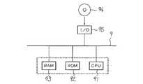
図20は、メインコントローラ26を中心とした電気的な接続を示すブロック図である。メインコントローラ26は、各種演算を行い、デジタル複写機1の各部を集中的に制御するCPU91が、汎用バス9を介してROM92、RAM93と接続されている。記憶媒体となるROM92には、図19を参照して前述した制御を行う制御プログラムが記憶されている。ROM92は、フラッシュメモリ等の不揮発性メモリも備えていてもよい。その場合、前述の制御プログラムは、光ディスクなどの記憶媒体94から光ディスク装置などの所定の装置により読み取って、I/Oポート95を介して不揮発性メモリに記憶させるようにして、前述の制御を行うようにしてもよい。
【0137】
【発明の効果】
請求項1,18,20に記載の発明は、複写機は記憶装置に記憶されている画像データを、外部のクライアントPCなどからの要求によりデータ形式の変換を行って、外部のクライアントPCなどで扱える形式に変換して出力することで、複写機の画像データを外部のクライアントPCなどでも利用することができる。また、複写機における画像データにもとづく場合でも、クライアントPCなどで受信した画像データにもとづく場合でも、複写機で画像形成した画像を同様の画質にすることができる。さらに、記憶装置に記憶済みの画像データに対してデータ形式を変換するので、同一画像データにつき複数の人が異なるデータ形式で画像データを受け取ることができる。
【0138】
請求項2,19に記載の発明は、請求項1,18に記載の発明において、外部のクライアントPCなどから要求されたとおりのデータ形式に変換して送信するので、送信先の需要に応じた形式の画像データを提供することができる。
【0139】
請求項3に記載の発明は、請求項1又は2に記載の発明において、複写機におけるデータフォーマットを外部のクライアントPCなどでも利用できるものに変えることができる。
【0140】
請求項4に記載の発明は、請求項3に記載の発明において、複写機における汎用のデータフォーマットを外部のクライアントPCなどでも利用できる他の汎用のデータフォーマットに変えることができる。
【0141】
請求項5に記載の発明は、請求項3に記載の発明において、複写機における専用のデータフォーマットを外部のクライアントPCなどでも利用できる他の汎用のデータフォーマットに変えることができる。
【0142】
請求項6に記載の発明は、請求項3に記載の発明において、複写機における専用のデータフォーマットを外部のクライアントPCなどでも利用できる他の専用のデータフォーマットに変えることができる。
【0143】
請求項7に記載の発明は、請求項2〜6のいずれかの一に記載の発明において、複写機における画像データがプリンタエンジンによる画像形成に適した色空間のものなどであっても、外部のクライアントPCなどでディスプレイ表示するのに適する色空間などに変換することができる。
【0144】
請求項8に記載の発明は、請求項7に記載の発明において、複写機における画像データがデバイスディペンデンスな色空間であっても、デバイスインディペンデントな色空間に変換して、外部のクライアントPCなどで利用しやすくすることができる。
【0145】
請求項9に記載の発明は、請求項2〜6のいずれかの一に記載の発明において、複写機における画像データが所定の色空間のものであっても、モノクロの2値又は多値画像データに変換して、モノクロの2値又は多値画像データとして利用したい外部のクライアントPCなどの需要を満足することができる。
【0146】
請求項10に記載の発明は、請求項9に記載の発明において、複写機における画像データをモノクロの多値画像データに変換してからモノクロの2値画像データに変換するので、モノクロの2値画像データに変換する前にさまざまな画像処理を行って、外部のクライアントPCなどの需要を満足することができる。
【0147】
請求項11に記載の発明は、請求項2〜6のいずれかの一に記載の発明において、複写機におけるモノクロの2値又は多値画像データ画像データであっても、所定の形式のモノクロの2値又は多値画像データに変換して送信し、かかる形式のモノクロの2値又は多値画像データとして利用したい外部のクライアントPCなどの需要を満足することができる。
【0148】
請求項12に記載の発明は、請求項10に記載の発明において、複写機における画像データをモノクロの多値画像データに変換してからモノクロの2値画像データに変換するので、モノクロの2値画像データに変換する前にさまざまな画像処理を行って送信し、外部のクライアントPCなどの需要を満足することができる。
【0149】
請求項13に記載の発明は、請求項2〜12のいずれかの一に記載の発明において、複写機における画像データを所定の解像度に変換して送信し、外部のクライアントPCなどの需要を満足することができる。
【0150】
請求項14に記載の発明は、請求項2〜10,12のいずれかの一に記載の発明において、複写機における画像データを空間フィルタ処理して送信し、外部のクライアントPCなどの需要を満足することができる。
【0151】
請求項15に記載の発明は、請求項2〜10,12のいずれかの一に記載の発明において、複写機における画像データをγ変換して送信し、外部のクライアントPCなどの需要を満足することができる。
【0152】
請求項16に記載の発明は、請求項2〜10,12のいずれかの一に記載の発明において、複写機における画像データに孤立点の除去の処理を行って送信し、外部のクライアントPCなどの需要を満足することができる。
【0153】
請求項17に記載の発明は、画像処理システムは記憶装置に記憶されている画像データを、外部のクライアントPCなどからの要求によりデータ形式の変換を行って、外部のクライアントPCなどで扱える形式に変換して出力することで、画像処理システムの画像データを外部のクライアントPCなどでも利用することができる。また、記憶装置に記憶済みの画像データに対してデータ形式を変換するので、同一画像データにつき複数の人が異なるデータ形式で画像データを受け取ることができる。
【図面の簡単な説明】
【図1】本発明の一実施の形態であるデジタル複写機の構成を説明するブロック図である。
【図2】スキャナ補正部の構成を示すブロック図である。
【図3】プリンタ補正部の構成を示すブロック図である。
【図4】画像データをデータ形式変換装置で処理して送信する場合の処理について説明するブロック図である。
【図5】データ形式変換装置の一構成例を示すブロック図である。
【図6】データ形式変換装置によりデータフォーマットの一例について説明する説明図である。
【図7】データ形式変換装置によりデータフォーマットの他の例について説明する説明図である。
【図8】データ形式変換装置によりデータフォーマットの他の例について説明する説明図である。
【図9】解像度変換器について説明する説明図である。
【図10】色空間変換器による色空間変換について説明する説明図である。
【図11】デジタル複写機がPCなどに画像データを出力する場合の処理について説明する説明図である。
【図12】データ形式変換装置の他の例を示すブロック図である。
【図13】フィルタによる処理について説明する説明図である。
【図14】γ変換処理について説明する説明図である。
【図15】孤立点除去の処理に用いるマトリックスの説明図である。
【図16】ディザ法について説明する説明図である。
【図17】誤差拡散法について説明する説明図である。
【図18】データ形式変換装置の他の例を示すブロック図である。
【図19】メインコントローラが実行する処理のフローチャートである。
【図20】メインコントローラの電気的な接続のブロック図である。
【符号の説明】
1 複写機、画像処理システム
11 記憶装置
12 画像読取装置
19 プリンタエンジン
94 記憶媒体[0001]
TECHNICAL FIELD OF THE INVENTION
The present invention relates to a copying machine, an image processing system, a program, and a storage medium.
[0002]
[Prior art]
A network in which a digital copying machine or an image reading device is connected to a network, an original image is scanned by a scanner of the digital copying machine or the image reading device, and the read image data is distributed to a terminal such as a computer connected to the network. A function called a scanner is known.
[0003]
For example,
[0004]
The processing procedure using the scanner box function is as follows. First, scanning parameters such as resolution, gradation, magnification, reading surface, image size, and storage destination are selected, and an image document is read. Then, the read image data is transferred to the image processing unit, and the image processing is performed according to the scan parameters. However, since print output of an image is not planned, it is not necessary to generate a data format of a print output system, and color coordinate system conversion from RGB to CMYK, gradation correction, and image data compression processing are omitted. You. Then, the image data after the image processing is transferred to the extension box. In the extension box, the received image data is temporarily stored in a scan box allocated to a predetermined disk area in the hard disk device, and when all document pages have been accumulated, a network client retrieves the image data from the scan box.
[0005]
[Patent Document 1]
JP 2000-333026 A
[0006]
[Problems to be solved by the invention]
However, in the technology disclosed in
[0007]
Also, when the scan parameters such as resolution, gradation, magnification, reading surface, image size, and save destination are selected from the operation unit on the personal computer as a client, the original is scanned, and the read image data is processed by the image processing unit. To the hard disk after performing image processing in accordance with the scan parameters, the image data after storage cannot be converted into an image format. When a person wants to receive a document under a different image format condition, the user has to scan again according to the requirements of each client.
[0008]
Furthermore, image data stored on the hard disk is often in a format dedicated to digital copiers, and may be compressed by a dedicated algorithm when compressing with a compression algorithm to save memory capacity. For this reason, there is also a problem that images cannot be viewed or edited by a general-purpose application even when the images are distributed to a personal computer.
[0009]
An object of the present invention is to form an image with a copying machine or the like in a copying machine or the like capable of transmitting image data to an external device, whether based on image data in the copying machine or the like or based on image data received by a client PC or the like. The purpose is to enable images to be of similar quality.
[0010]
Another object of the present invention is to convert a data format of image data stored in a storage device, so that a plurality of persons can receive image data of the same image data in different data formats.
[0011]
[Means for Solving the Problems]
The invention according to
[0012]
Accordingly, the copier converts the image data stored in the storage device into a format that can be handled by the external client PC or the like by performing a data format conversion in response to a request from the external client PC or the like, and outputs the converted data. The image data of the copying machine can be used by an external client PC or the like. Further, the image formed by the copying machine can have the same image quality whether it is based on image data in the copying machine or based on image data received by a client PC or the like. Furthermore, since the data format is converted for the image data already stored in the storage device, a plurality of persons can receive the image data in different data formats for the same image data.
[0013]
According to a second aspect of the present invention, in the copying machine according to the first aspect, the accepting unit also accepts the designation of the second format, and the data format converting unit includes the converted image data. In the designated second format.
[0014]
Therefore, since the data is converted into the data format requested by the external client PC and transmitted, it is possible to provide image data in a format according to the demand of the transmission destination.
[0015]
According to a third aspect of the present invention, in the copying machine according to the first or second aspect, the data format conversion means changes a data format between the second format and the first format. It is characterized by.
[0016]
Therefore, the data format in the copying machine can be changed to a format that can be used by an external client PC or the like.
[0017]
According to a fourth aspect of the present invention, in the copying machine according to the third aspect, a general-purpose data format is used for both the first format and the second format.
[0018]
Therefore, the general-purpose data format in the copying machine can be changed to another general-purpose data format that can be used by an external client PC or the like.
[0019]
According to a fifth aspect of the present invention, in the copying machine according to the third aspect, the first format is dedicated to the apparatus, and the second format is a general-purpose data format. I do.
[0020]
Therefore, the exclusive data format in the copying machine can be changed to another general-purpose data format that can be used by an external client PC or the like.
[0021]
According to a sixth aspect of the present invention, in the copying machine according to the third aspect, both the first format and the second format use a data format dedicated to the apparatus.
[0022]
Therefore, the exclusive data format in the copying machine can be changed to another exclusive data format that can be used by an external client PC or the like.
[0023]
According to a seventh aspect of the present invention, in the copying machine according to any one of the second to sixth aspects, the data format conversion unit performs color conversion of the image data in the first format and the second format. Change the space.
[0024]
Therefore, even if the image data in the copying machine is in a color space suitable for image formation by the printer engine, it can be converted to a color space suitable for display display on an external client PC or the like.
[0025]
According to an eighth aspect of the present invention, in the copying machine according to the seventh aspect, the data format conversion unit uses the color space of the second format as a device-independent color space. .
[0026]
Therefore, even if the image data in the copying machine is in a device-dependent color space, the image data can be converted into a device-independent color space and can be easily used by an external client PC or the like.
[0027]
According to a ninth aspect of the present invention, in the copying machine according to any one of the second to sixth aspects, the data format conversion unit is configured to output the data when the first format is image data in a predetermined color space. It is characterized in that the second format is monochrome binary or multi-valued image data.
[0028]
Therefore, even if the image data in the copier is in a predetermined color space, an external client PC or the like who wants to convert the image data into monochrome binary or multi-valued image data and use it as monochrome binary or multi-valued image data Can satisfy the demand.
[0029]
According to a tenth aspect of the present invention, in the copying machine according to the ninth aspect, when the second format is monochrome binary image data, the data format conversion unit outputs the first format image data. Is converted into monochrome multi-valued image data and then converted into the second format.
[0030]
Therefore, since the image data in the copier is converted into monochrome multi-valued image data and then converted into monochrome binary image data, various image processings are performed before conversion into monochrome binary image data to perform external image processing. Can satisfy the demand for client PCs.
[0031]
According to an eleventh aspect of the present invention, in the copying machine according to any one of the second to sixth aspects, the data format conversion means is configured such that the first format is monochrome binary or multi-valued image data. Sometimes, the second format is monochrome binary or multi-valued image data.
[0032]
Therefore, even if the image data is monochrome binary or multi-valued image data in a copying machine, the image data is converted into monochrome binary or multi-valued image data of a predetermined format and transmitted. It is possible to satisfy the demand of an external client PC or the like that is desired to be used as value image data.
[0033]
According to a twelfth aspect of the present invention, in the copying machine according to the tenth aspect, the data format conversion means converts the image data of the first format into multi-valued image data and then converts the image data to the second format. Is performed.
[0034]
Therefore, since the image data in the copying machine is converted into monochrome multi-valued image data and then converted into monochrome binary image data, various image processings are performed and converted before being converted into monochrome binary image data. , The demand for external client PCs and the like can be satisfied.
[0035]
According to a thirteenth aspect of the present invention, in the copying machine according to any one of the second to twelfth aspects, the data format conversion unit converts the image data of the second format into a resolution different from that of the first format. It is characterized by the following.
[0036]
Therefore, the image data in the copying machine can be converted into a predetermined resolution and transmitted, thereby satisfying the demand of an external client PC or the like.
[0037]
According to a fourteenth aspect of the present invention, in the copying machine according to any one of the second to tenth and twelfth aspects, the data format conversion unit performs a spatial filter process on the image data of the first format. It is characterized by the following.
[0038]
Therefore, the image data in the copying machine can be spatially filtered and transmitted, and the demand for an external client PC or the like can be satisfied.
[0039]
According to a fifteenth aspect of the present invention, in the copying machine according to any one of the second to tenth and twelfth aspects, the data format conversion unit performs γ conversion on the image data of the first format. It is characterized by.
[0040]
Therefore, the image data in the copying machine can be γ-converted and transmitted, and the demand for an external client PC or the like can be satisfied.
[0041]
According to a sixteenth aspect of the present invention, in the copying machine according to any one of the second to tenth and twelfth aspects, the data format conversion unit removes an isolated point from the image data in the first format. Is performed.
[0042]
Therefore, it is possible to satisfy the demand of an external client PC or the like by transmitting the image data in the copier after performing the process of removing the isolated point.
[0043]
The invention according to
[0044]
Therefore, the image processing system converts the image data stored in the storage device into a format that can be handled by an external client PC or the like by performing a data format conversion in response to a request from an external client PC or the like and outputs the converted data. The image data of the image processing system can be used by an external client PC or the like. Further, since the data format is converted for the image data already stored in the storage device, a plurality of persons can receive the image data in different data formats for the same image data.
[0045]
The invention according to claim 18 controls a copying machine including an image reading device that reads an image of a document, and a printer engine that forms an image on a medium based on the read image data of the document. In a computer readable program, a storage process of storing the data format of the image data in a predetermined first format in a storage device, a reception process of receiving a request for transmission of the image data from outside, A first data format conversion process of converting the data format of the image data being received from the first format to a predetermined second format, and, if received, transferring the converted image data to a predetermined destination And a transmission process for causing the copying machine to execute the transmission process.
[0046]
Accordingly, the copier converts the image data stored in the storage device into a format that can be handled by the external client PC or the like by performing a data format conversion in response to a request from the external client PC or the like, and outputs the converted data. The image data of the copying machine can be used by an external client PC or the like. Further, the image formed by the copying machine can have the same image quality whether it is based on image data in the copying machine or based on image data received by a client PC or the like. Furthermore, since the data format is converted for the image data already stored in the storage device, a plurality of persons can receive the image data in different data formats for the same image data.
[0047]
According to a nineteenth aspect of the present invention, in the program according to the eighteenth aspect, the accepting process also accepts the designation of the second format, and the data format converting process converts the converted image data. The second format is designated.
[0048]
Therefore, since the data is converted into the data format requested by the external client PC and transmitted, it is possible to provide image data in a format according to the demand of the transmission destination.
[0049]
The invention according to
[0050]
Therefore, the same operation and effect as the invention described in
[0051]
BEST MODE FOR CARRYING OUT THE INVENTION
An embodiment of the present invention will be described.
[0052]
FIG. 1 is a block diagram illustrating a configuration of a digital copying
[0053]
The functions of the digital copying
[0054]
First, the
[0055]
As shown in FIG. 1, the 8-bit CMYK color data processed by the
[0056]
Under the control of the
[0057]
When outputting image data, the image data in the
[0058]
As shown in FIG. 3, in the
[0059]
As shown in FIG. 1, a
[0060]
As shown in FIG. 4, the image data stored in the
[0061]
In the above description, the case where image data compressed in the CMYK color space is stored in the
[0062]
Next, the configuration of the data
[0063]
Next, a more specific configuration example of the data
[0064]
First, in the example of FIG. 6, the image data input to the
[0065]
In this example, JPEG is used as a general-purpose data format, but other general-purpose data formats, such as JPEG2000, which can be generally used in a PC or the like can be used.
[0066]
In this way, by transmitting and receiving data in a standardized general-purpose data format such as JPEG, the data format between units to be transmitted and received can be unified. Furthermore, a data format conversion system that maintains both data quality and data transmission / reception efficiency can be constructed.
[0067]
When the image data is binary data, a general-purpose standard image compression / decompression format such as the MHMR / MMR method can be used.
[0068]
In the example of FIG. 7, the image data input to the
[0069]
Therefore, the
[0070]
In the example of FIG. 7, since the dedicated data format is the dedicated block fixed-length compressed data, it is possible to fix and manage the fluctuation of the compression ratio due to the image data in particular. Further, by handling in block units, data processing such as rotation and rearrangement of the image direction becomes easy. Since the fixed-length block coding and decoding methods are known, detailed description thereof will be omitted (if necessary, refer to JP-A-11-331844). When the image data is binary data, for example, the technology disclosed in JP-A-2002-077627 can be used.
[0071]
In addition, by transmitting image data in a standardized general-purpose data format such as JPEG, the data format of the unit to be transmitted can be unified, and both data quality and data transmission / reception efficiency are maintained. A data format conversion system can be constructed.
[0072]
When the image data is binary data, the
[0073]
In the example of FIG. 8, unlike the example of FIG. 7, the image data output from the
[0074]
As described above, since the dedicated data format is the dedicated block fixed-length compressed data, it is possible to fix and manage particularly a change in the compression ratio due to the image data. Further, by processing the image data in block units, data processing such as rotation and rearrangement of the image direction becomes easy. Since the method of block fixed-length encoding and decoding is known, detailed description thereof is omitted (if necessary, refer to JP-A-11-331844). When the image data is binary data, for example, the technology disclosed in JP-A-2002-077627 can be used.
[0075]
Next, the
[0076]
In this example, an example of a method in which pixel data to be processed is multi-valued data and conversion to an arbitrary resolution in both the main scanning direction and the sub-scanning direction will be described. As shown in FIG. 9A, the
[0077]
As shown in FIG. 9B, in the main scanning
[0078]
As shown in FIG. 9C, the data after the resolution conversion in the main scanning direction is stored in the sub-scanning
[0079]
Next, the color space conversion function of the
[0080]
Hereinafter, an example in which color space conversion is performed by a table interpolation method as an example of color space conversion will be described.
[0081]
In this processing, a predetermined look-up table (LUT) is used. Here, each axis in the xyz direction is divided into eight parts (see FIG. 10A), the input color space is divided into upper and lower parts, the LUT is referred to in the upper part, and three-dimensional interpolation is performed in the lower part to output a precise output. obtain.
[0082]
There are many types of three-dimensional interpolation methods. Here, the simplest tetrahedron interpolation method among linear interpolation will be described as an example. In the tetrahedral interpolation method, as shown in FIG. 10A, the input color space is divided into a plurality of unit cubes, and further divided into six tetrahedrons sharing the symmetry axis of the unit cube (FIG. b)). As a result, the input color signal refers to a parameter (hereinafter, referred to as a grid point parameter) of a division boundary point (grid point) of the unit tetrahedron (FIG. 10C) selected by the upper coordinate of the input color signal from the LUT. Next, an output value can be obtained by performing a linear operation from the lattice point parameters of the unit tetrahedron selected by the lower coordinates.
[0083]
The actual processing procedure is as follows.
[0084]
1. A unit cube containing the input color signal X (x, y, z) is selected.
[0085]
2. The lower coordinates (lx, lly, llz) of the coordinates P in the selected unit cube are obtained.
[0086]
3. A unit tetrahedron is selected by comparing lower-order coordinates, linear interpolation is performed for each unit tetrahedron, and an output value P at coordinates P is obtained.outAsk for. The arithmetic expression of the linear interpolation of each unit tetrahedron is represented by the following expression (where the symbol “l” indicates the length of one side of the unit cube).
[0087]
(Lx <ly <lz) Pout= P2 + (P5-P7) × lx / l + (P7-P8) × ly / l + (P8-P2) × lz / l
(Ly ≦ lx <lz) Pout= P2 + (P6-P8) × lx / l + (P5-P6) × ly / l + (P8-P2) × lz / l
(Ly <lz ≦ lx) Pout= P2 + (P4-P2) × lx / l + (P5-P6) × ly / l + (P6-P4) × lz / l
(Lz ≦ ly ≦ lx) Pout= P2 + (P4-P2) × lx / l + (P3-P4) × ly / l + (P5-P3) × lz / l
(Lz ≦ lx <ly) Pout= P2 + (P3-P1) × lx / l + (P1-P2) × ly / l + (P5-P3) × lz / l
(Lx <lz ≦ ly) Pout= P2 + (P5-P7) × lx / l + (P1-P1) × ly / l + (P7-P1) × lz / l
Next, a process for outputting image data to the
[0088]
The parameters of the
[0089]
As described above, the image data stored in the
[0090]
Here, for example, the image data stored in the
Client A is a JPEG image in 200 dpi resolution RGB space
Client B is a TIFF image in 400 dpi Yuv space
Client C is a JPEG2000 image in 100 dpi Lab space
The
[0091]
The
[0092]
In this example, since the image data stored in the
[0093]
Next, the
[0094]
The
[0095]
The image data stored in the
[0096]
Thus, when the client receives (captures) an image from the
[0097]
Next, another configuration example of the data
[0098]
In the above-described example, it is basically assumed that image data in one color space stored in the
[0099]
FIG. 12 is a block diagram illustrating another configuration example of the data
[0100]
With the
[0101]
Next, details of the blocks in FIG. 12 will be described.
[0102]
First, the color conversion of the CMYK →
[0103]
The processing of the
[0104]
When the MTF of the image data is increased, the image frequency of the base image is indicated by a solid line, and the image frequency after the filter processing is indicated by a broken line. As shown in FIG. Perform processing. However, the vertical axis represents the dynamic range of the image density, and the horizontal axis represents the raster format reference of the image data.
[0105]
Similarly, when smoothing the MTF of the image data, as shown in FIG. 13B, a process is performed so that the uplift of the image frequency becomes dull. In actual processing, the raster direction of the two-dimensional image data is set to the line direction (x direction), the other direction is set to the y direction, the image data is handled in units of lines, and the pixel value of interest is calculated based on the peripheral pixel values. I do.
[0106]
FIG. 13C shows that 5 × 5 pixels around the target pixel are represented by X and the target pixel is represented by X.n, m, Peripheral pixels are symbolized and represented.
[0107]
To increase the MTF of image data, a coefficient (hereinafter, referred to as a matrix coefficient) in which the differential coefficients of the image frequency that need to be emphasized are arranged in a matrix based on the resolution of the image data is calculated. The matrix coefficient is converted into the same format as the surrounding pixel symbol,m-2, n-2, Am-2, n-1, ..., Am, n, Am+2, n+1, Am+2, n+2When the MTF of the image data is increased, the target pixel value Y after the filter processing can be expressed by the following arithmetic expression.
[0108]
[0109]
In the case of smoothing the image data, the average value of the target pixel and its peripheral pixels is obtained by adding the target pixel and its peripheral pixels and dividing by the number E of pixels. By performing such an operation, all pixels of the image data are converted to perform an operation of smoothing the image data. In order to adjust the degree of smoothing, if the weights of the target pixel and the peripheral pixels are not simply averaged as equivalents but are spaced apart from each other, the matrix coefficients are calculated as shown in the following equation (4). The target pixel value Y can be adjusted by substituting an arbitrary integer.
[0110]
[0111]
Next, the processing performed by the
[0112]
The γ-conversion process makes the density gradient and density characteristics of an image variable. As shown in FIG. 14, when the solid line in FIG. 14A is a γ conversion table, the value corresponding to the original image data (horizontal axis) is converted into the value of the image data (vertical axis) after γ conversion according to the graph. Just convert it to By changing the curve of this conversion table, it is possible to change to image data having a target density distribution. For example, if a gamma conversion table as shown by a broken line in FIG. 14A is used, image data after gamma conversion is converted into image data with a smooth density gradient as compared with a gamma conversion table shown by a solid line. be able to. However, in FIG. 14A, the density becomes higher as going to the arrow side of the figure.
[0113]
The method of creating the γ-conversion table will be described based on a linear γ-conversion table (solid line) shown in FIG.
[0114]
To increase or decrease the overall density of the image without changing the density characteristics, the image may be translated in the horizontal axis direction of the graph as shown in the γ-conversion table (broken line) as shown in FIG. When changing the density gradient, the gradient of the γ conversion table may be changed. Further, when changing the density characteristic, an arbitrary density characteristic can be obtained by changing the degree of curvature of the γ conversion table as shown by a continuous curve as shown in FIG.
[0115]
By these means, the
[0116]
The processing of the isolated
[0117]
The isolated
[0118]
By performing such processing, a dust image in the image read by the
[0119]
When the image data stored in the
[0120]
Therefore, a high-quality image can be obtained by appropriately switching the operation parameters of the isolated point removal according to the type of the image transferred to the
[0121]
Next, the processing executed by the
[0122]
The
[0123]
First, in the simple quantization method, image data is binarized using an arbitrary value in a dynamic range of multi-valued image data as a threshold value. For example, when quantizing multi-valued image data of 256 gradations with a dynamic range of 0 to 255 to values of 0 and 1, if the threshold value is 128 and the image data is 100, the quantization value is If it is 0 or 200, the quantization value is 1.
[0124]
The dither method uses the threshold values in the form of a matrix, and as shown in FIG. 16, the
[0125]
The error diffusion method performs binarization at an arbitrary threshold value as in the simple quantization method, but accumulates a quantization error generated at the time of quantization, and a pixel of interest being processed is rasterized. A halftone that attempts to minimize errors due to quantization in the total image data by performing quantization taking into account errors in peripheral pixels for which quantization processing has already been completed and errors have been determined in the format order. Processing.
[0126]
The error that occurs when quantizing is, for example, when quantizing multi-valued image data having a dynamic range of 256 tones from 0 to 255 into values of 0 and 1, if the image data is 100, Although the digitized value is 0, the image data is treated as the lowest value of 0, even though the image data has intermediate density information of 100, and the intermediate density information of the image data is lost. Therefore, the quantization error of this image data is "100 = 100-0" (the lowest value of the dynamic range). If the image data is 200, the quantization value is 1. In this case, the image data is treated as the maximum value of 1 even though the intermediate density information of 200 is present. The conversion error is “−55 = 200−255” (the maximum value of the dynamic range).
[0127]
If these quantization error values are stored as data different from the image data after the quantization processing for each pixel is completed, the
[0128]
With these methods, the
[0129]
FIG. 18 is a block diagram illustrating another configuration example of the data
[0130]
The
[0131]
Thus, predetermined processing can be performed on the monochrome binary image data stored in the
[0132]
In both the example of FIG. 12 and the example of FIG. 16, as described with reference to FIGS. 6 to 8, both the input data and the output data to the data
[0133]
Next, a series of processes performed by the digital copying
[0134]
First, when the
[0135]
Thus, for example, when the
[0136]
FIG. 20 is a block diagram showing an electrical connection centering on the
[0137]
【The invention's effect】
According to the inventions described in
[0138]
According to the inventions described in
[0139]
According to a third aspect of the present invention, in the first or second aspect, the data format in the copying machine can be changed to a format that can be used by an external client PC or the like.
[0140]
According to a fourth aspect of the present invention, in the third aspect, the general-purpose data format in the copying machine can be changed to another general-purpose data format that can be used by an external client PC or the like.
[0141]
According to a fifth aspect of the present invention, in the third aspect of the present invention, the exclusive data format in the copying machine can be changed to another general-purpose data format that can be used by an external client PC or the like.
[0142]
According to a sixth aspect of the present invention, in the third aspect, a dedicated data format in the copying machine can be changed to another dedicated data format that can be used by an external client PC or the like.
[0143]
According to a seventh aspect of the present invention, in the invention of any one of the second to sixth aspects, even if the image data in the copying machine is of a color space suitable for image formation by a printer engine, the external device may be an external device. Can be converted to a color space suitable for display display on a client PC or the like.
[0144]
According to an eighth aspect of the present invention, in the invention of the seventh aspect, even if the image data in the copying machine is in a device-dependent color space, the image data is converted into a device-independent color space, and an external It can be easily used on a client PC or the like.
[0145]
According to a ninth aspect of the present invention, there is provided the image processing apparatus according to any one of the second to sixth aspects, wherein even if the image data in the copying machine is of a predetermined color space, a monochrome binary or multilevel image is obtained. By converting the data into data, it is possible to satisfy the demand of an external client PC or the like that wants to use it as monochrome binary or multivalued image data.
[0146]
According to a tenth aspect of the present invention, in the ninth aspect, the image data in the copying machine is converted into monochrome multi-valued image data and then converted into monochrome binary image data. Various image processing can be performed before conversion to image data to satisfy the demand of an external client PC or the like.
[0147]
According to an eleventh aspect of the present invention, in the invention according to any one of the second to sixth aspects, even if the image data is monochrome binary or multivalued image data in a copying machine, a monochrome monochrome or multivalued image data of a predetermined format is used. It can be converted into binary or multi-valued image data and transmitted to satisfy the demand of an external client PC or the like that wants to use as monochrome binary or multi-valued image data of such a format.
[0148]
According to a twelfth aspect of the present invention, in the invention of the tenth aspect, since the image data in the copying machine is converted into monochrome multi-valued image data and then converted into monochrome binary image data, the monochrome binary image data is converted. Before conversion into image data, various image processings are performed and transmitted, so that the demand for an external client PC or the like can be satisfied.
[0149]
According to a thirteenth aspect of the present invention, in the invention according to any one of the second to twelfth aspects, the image data in the copying machine is converted into a predetermined resolution and transmitted to satisfy the demand of an external client PC or the like. can do.
[0150]
According to a fourteenth aspect of the present invention, in the invention of any one of the second to tenth and twelfth aspects, the image data in the copying machine is spatially filtered and transmitted to satisfy the demand of an external client PC or the like. can do.
[0151]
According to a fifteenth aspect of the present invention, in the invention of any one of the second to tenth and twelfth aspects, the image data in the copying machine is γ-converted and transmitted, thereby satisfying the demand of an external client PC or the like. be able to.
[0152]
According to a sixteenth aspect of the present invention, in the invention according to any one of the second to tenth and twelfth aspects, the image data in the copying machine is subjected to isolated point removal processing and transmitted, and an external client PC or the like is used. Can satisfy the demand.
[0153]
According to a seventeenth aspect of the present invention, the image processing system converts the image data stored in the storage device into a format that can be handled by an external client PC or the like by performing a data format conversion in response to a request from an external client PC or the like. By converting and outputting, the image data of the image processing system can be used by an external client PC or the like. Further, since the data format is converted for the image data already stored in the storage device, a plurality of persons can receive the image data in different data formats for the same image data.
[Brief description of the drawings]
FIG. 1 is a block diagram illustrating a configuration of a digital copying machine according to an embodiment of the present invention.
FIG. 2 is a block diagram illustrating a configuration of a scanner correction unit.
FIG. 3 is a block diagram illustrating a configuration of a printer correction unit.
FIG. 4 is a block diagram illustrating processing when image data is processed by a data format conversion apparatus and transmitted.
FIG. 5 is a block diagram illustrating a configuration example of a data format conversion device.
FIG. 6 is an explanatory diagram illustrating an example of a data format by a data format conversion device.
FIG. 7 is an explanatory diagram illustrating another example of a data format by the data format conversion device.
FIG. 8 is an explanatory diagram illustrating another example of a data format by the data format conversion device.
FIG. 9 is an explanatory diagram illustrating a resolution converter.
FIG. 10 is an explanatory diagram illustrating color space conversion by a color space converter.
FIG. 11 is an explanatory diagram illustrating a process when a digital copying machine outputs image data to a PC or the like.
FIG. 12 is a block diagram showing another example of the data format conversion device.
FIG. 13 is an explanatory diagram illustrating processing by a filter.
FIG. 14 is an explanatory diagram illustrating gamma conversion processing.
FIG. 15 is an explanatory diagram of a matrix used for an isolated point removal process.
FIG. 16 is an explanatory diagram illustrating a dither method.
FIG. 17 is an explanatory diagram illustrating an error diffusion method.
FIG. 18 is a block diagram showing another example of the data format conversion device.
FIG. 19 is a flowchart of a process executed by a main controller.
FIG. 20 is a block diagram of electrical connection of a main controller.
[Explanation of symbols]
1 Copier, image processing system
11 Storage device
12 Image reading device
19 Printer Engine
94 storage media
Claims (20)
Translated fromJapanese前記画像データについてそのデータ形式を所定の第1の形式で記憶装置に記憶する記憶手段と、
所定の送信先への前記画像データの送信の要求を受け付ける受付手段と、
この記憶している画像データのデータ形式を前記第1の形式から所定の第2の形式に変換するデータ形式変換手段と、
前記受付があったときは前記変換後の画像データを前記所定の送信先に送信する送信手段と、
を備えていることを特徴とする複写機。A copier including: an image reading device that reads an image of a document; and a printer engine that forms an image on a medium based on the read image data of the document.
Storage means for storing a data format of the image data in a predetermined first format in a storage device;
Receiving means for receiving a request for transmission of the image data to a predetermined destination,
Data format conversion means for converting the data format of the stored image data from the first format to a predetermined second format;
A transmission unit that transmits the converted image data to the predetermined destination when the reception is performed,
A copying machine comprising:
前記データ形式変換手段は、前記変換後の画像データを前記指定された第2の形式とする、
ことを特徴とする請求項1に記載の複写機。The receiving means also receives the specification of the second format,
The data format conversion unit sets the converted image data to the specified second format.
The copying machine according to claim 1, wherein:
前記画像データについてそのデータ形式を所定の第1の形式で記憶装置に記憶する記憶手段と、
外部から前記画像データの送信の要求を受け付ける受付手段と、
この記憶している画像データのデータ形式を前記第1の形式から所定の第2の形式に変換するデータ形式変換手段と、
前記受付があったときは前記変換後の画像データを所定の送信先に送信する送信手段と、
を備えていることを特徴とする画像処理システム。In an image processing system that performs predetermined processing based on image data,
Storage means for storing a data format of the image data in a predetermined first format in a storage device;
Receiving means for receiving a request for transmission of the image data from outside;
Data format conversion means for converting the data format of the stored image data from the first format to a predetermined second format;
Transmitting means for transmitting the converted image data to a predetermined destination when the reception is performed,
An image processing system comprising:
前記画像データについてそのデータ形式を所定の第1の形式で記憶装置に記憶する記憶処理と、
外部から前記画像データの送信の要求を受け付ける受付処理と、
この記憶している画像データのデータ形式を前記第1の形式から所定の第2の形式に変換する第1のデータ形式変換処理と、
前記受付があったときは前記変換後の画像データを所定の送信先に送信する送信処理と、
を複写機に実行させることを特徴とするプログラム。An image reading device that reads an image of a document, and a printer engine that forms an image on a medium based on the image data of the read document, and a program that can be read by a computer that controls a copying machine including:
A storage process of storing the data format of the image data in a predetermined first format in a storage device;
A reception process for receiving a request for transmission of the image data from outside,
A first data format conversion process for converting the data format of the stored image data from the first format to a predetermined second format;
A transmission process of transmitting the converted image data to a predetermined transmission destination when the reception is received;
For causing a copying machine to execute the following.
前記データ形式変換処理は、前記変換後の画像データを前記指定された第2の形式とする、
ことを特徴とする請求項18に記載のプログラム。The receiving process also receives the specification of the second format,
The data format conversion processing sets the converted image data to the specified second format.
The program according to claim 18, wherein:
Priority Applications (3)
| Application Number | Priority Date | Filing Date | Title |
|---|---|---|---|
| JP2003130283AJP2004336453A (en) | 2003-05-08 | 2003-05-08 | Copying machine, image processing system, program and storage medium |
| US10/838,345US20050024666A1 (en) | 2003-05-08 | 2004-05-05 | Copying apparatus, a program, and a storage medium |
| EP20040252671EP1475952A3 (en) | 2003-05-08 | 2004-05-07 | A copying apparatus, a program, and a storage medium |
Applications Claiming Priority (1)
| Application Number | Priority Date | Filing Date | Title |
|---|---|---|---|
| JP2003130283AJP2004336453A (en) | 2003-05-08 | 2003-05-08 | Copying machine, image processing system, program and storage medium |
Publications (1)
| Publication Number | Publication Date |
|---|---|
| JP2004336453Atrue JP2004336453A (en) | 2004-11-25 |
Family
ID=32985654
Family Applications (1)
| Application Number | Title | Priority Date | Filing Date |
|---|---|---|---|
| JP2003130283APendingJP2004336453A (en) | 2003-05-08 | 2003-05-08 | Copying machine, image processing system, program and storage medium |
Country Status (3)
| Country | Link |
|---|---|
| US (1) | US20050024666A1 (en) |
| EP (1) | EP1475952A3 (en) |
| JP (1) | JP2004336453A (en) |
Cited By (2)
| Publication number | Priority date | Publication date | Assignee | Title |
|---|---|---|---|---|
| JP2005304012A (en)* | 2004-03-19 | 2005-10-27 | Ricoh Co Ltd | Image processing apparatus, image processing method, and image processing program |
| JP2010172001A (en)* | 2004-03-19 | 2010-08-05 | Ricoh Co Ltd | Image processing apparatus, image processing method and image processing program |
Families Citing this family (16)
| Publication number | Priority date | Publication date | Assignee | Title |
|---|---|---|---|---|
| JP2004341760A (en)* | 2003-05-15 | 2004-12-02 | Ricoh Co Ltd | Image forming apparatus, program, and storage medium |
| US20050046881A1 (en)* | 2003-07-15 | 2005-03-03 | Takeharu Tone | Image processing apparatus, program, computer-readable storage medium, and image processing method that can use stored image data for various purposes |
| CN1728761A (en) | 2004-06-16 | 2006-02-01 | 株式会社理光 | Image processing device, image processing method, and image processing program |
| US7796287B2 (en)* | 2005-02-04 | 2010-09-14 | Canon Kabushiki Kaisha | Image processing system, image processing device, and audit data transfer mode |
| JP2006333110A (en)* | 2005-05-26 | 2006-12-07 | Konica Minolta Business Technologies Inc | Color image forming apparatus |
| US7619639B1 (en)* | 2005-09-12 | 2009-11-17 | Nvidia Corporation | Adaptive scaling using a programmable video engine |
| JP4755569B2 (en)* | 2006-11-13 | 2011-08-24 | 株式会社リコー | Image processing apparatus and image processing method |
| JP4933932B2 (en)* | 2007-03-23 | 2012-05-16 | ソニー株式会社 | Information processing system, information processing apparatus, information processing method, and program |
| JP4990751B2 (en)* | 2007-12-25 | 2012-08-01 | 京セラドキュメントソリューションズ株式会社 | Image processing apparatus and image reading apparatus |
| JP5258503B2 (en)* | 2008-10-22 | 2013-08-07 | キヤノン株式会社 | Copy machine |
| JP5477081B2 (en)* | 2010-03-16 | 2014-04-23 | 株式会社リコー | Image processing apparatus, image processing method, and program |
| JP5609308B2 (en)* | 2010-06-24 | 2014-10-22 | 株式会社リコー | Image processing system, image processing apparatus, information processing apparatus, and image processing method |
| JP2014110306A (en)* | 2012-11-30 | 2014-06-12 | Canon Inc | Drawing device, and manufacturing method of article |
| JP6311364B2 (en)* | 2014-03-10 | 2018-04-18 | セイコーエプソン株式会社 | Print server, print system, print management program, and print management method |
| JP6572698B2 (en)* | 2015-09-15 | 2019-09-11 | 富士ゼロックス株式会社 | Information processing apparatus, information processing system, and program |
| JP7424076B2 (en) | 2020-01-29 | 2024-01-30 | 株式会社リコー | Image processing device, image processing system, imaging device, image processing method and program |
Family Cites Families (64)
| Publication number | Priority date | Publication date | Assignee | Title |
|---|---|---|---|---|
| US5028992A (en)* | 1988-08-25 | 1991-07-02 | Ricoh Company, Ltd. | Image combining apparatus for a digital color copier |
| JP3181333B2 (en)* | 1990-11-30 | 2001-07-03 | 株式会社リコー | Folding order image forming device |
| US5251202A (en)* | 1991-05-23 | 1993-10-05 | Ricoh Company, Ltd. | Optical information recording medium having multi-layered structures for preventing undesired reflection and electric charging |
| JP3183691B2 (en)* | 1991-11-19 | 2001-07-09 | 株式会社リコー | Image synthesis device |
| JP3183698B2 (en)* | 1992-02-28 | 2001-07-09 | 株式会社リコー | Image reading device |
| JPH06188937A (en)* | 1992-12-16 | 1994-07-08 | Canon Inc | Data processing device |
| JPH0818777A (en)* | 1994-03-08 | 1996-01-19 | Ricoh Co Ltd | Image processing device |
| JP3517757B2 (en)* | 1994-04-27 | 2004-04-12 | 株式会社リコー | Image processing device |
| US5687006A (en)* | 1994-04-28 | 1997-11-11 | Ricoh Company Ltd. | Image regenerating apparatus having improved character resolution and pattern gradation |
| US5715070A (en)* | 1994-04-28 | 1998-02-03 | Ricoh Company, Ltd. | Freely configurable image processing apparatus |
| US5726778A (en)* | 1994-09-16 | 1998-03-10 | Canon Kabushiki Kaisha | Image processing apparatus with color-space conversion |
| JPH0937013A (en)* | 1995-07-25 | 1997-02-07 | Fujitsu Ltd | Image scanner and network connection method of image scanner |
| US6069706A (en)* | 1995-07-31 | 2000-05-30 | Canon Kabushiki Kaisha | Image reading device and image processing method utilizing the same |
| JPH1039281A (en)* | 1996-07-19 | 1998-02-13 | Ricoh Co Ltd | Liquid crystal display device |
| US5911044A (en)* | 1996-11-08 | 1999-06-08 | Ricoh Company, Ltd. | Network image scanning system which transmits image information from a scanner over a network to a client computer |
| JPH10271300A (en)* | 1997-03-24 | 1998-10-09 | Ricoh Co Ltd | Image copier |
| GB9715257D0 (en)* | 1997-07-21 | 1997-09-24 | Rank Xerox Ltd | Context-sensitive document transactions |
| JPH11103392A (en)* | 1997-09-26 | 1999-04-13 | Ricoh Co Ltd | Image processing circuit |
| JPH11177744A (en)* | 1997-12-08 | 1999-07-02 | Ricoh Co Ltd | Digital linked copy system |
| US6462837B1 (en)* | 1998-03-05 | 2002-10-08 | Ricoh Company, Ltd. | Gray-scale conversion based on SIMD processor |
| JP3733446B2 (en)* | 1998-03-12 | 2006-01-11 | 株式会社リコー | Digital copier |
| US6404512B1 (en)* | 1998-07-06 | 2002-06-11 | Ricoh Company, Ltd. | Method and apparatus for image processing capable of efficiently performing a gamma conversion operation |
| JP3417305B2 (en)* | 1998-07-27 | 2003-06-16 | セイコーエプソン株式会社 | Printer, printer control device and image input / output device |
| JP3556859B2 (en)* | 1998-09-08 | 2004-08-25 | 富士写真フイルム株式会社 | Image correction method, image correction device, and recording medium |
| JP2000137391A (en)* | 1998-10-30 | 2000-05-16 | Ricoh Co Ltd | Intermediate transfer type image forming apparatus |
| US6988123B2 (en)* | 1998-11-06 | 2006-01-17 | Seiko Epson Corporation | Methods and apparatus for remote execution of an application over the internet |
| US6788441B1 (en)* | 1999-01-28 | 2004-09-07 | Ricoh Company, Ltd. | Color image processing apparatus, image processing apparatus, color image processing method, image processing method, and a computer-readable recording medium for making a computer execute the methods |
| JP3395691B2 (en)* | 1999-02-09 | 2003-04-14 | 富士ゼロックス株式会社 | Image reading device |
| DE60027637T2 (en)* | 1999-05-06 | 2006-09-28 | Seiko Epson Corp. | Network management system |
| JP3664926B2 (en)* | 1999-11-17 | 2005-06-29 | 株式会社リコー | Image processing device |
| US6961139B1 (en)* | 1999-11-30 | 2005-11-01 | Konica Corporation | Image forming system, method for storing image data and memory media |
| JP3660182B2 (en)* | 1999-12-03 | 2005-06-15 | 株式会社リコー | Image processing device |
| JP2001169068A (en)* | 1999-12-14 | 2001-06-22 | Ricoh Co Ltd | IMAGE PROCESSING DEVICE, IMAGE PROCESSING METHOD, AND COMPUTER-READABLE RECORDING MEDIUM RECORDING PROGRAM FOR CAUSING COMPUTER TO EXECUTE THE METHOD |
| US7038818B2 (en)* | 1999-12-27 | 2006-05-02 | Ricoh Company, Ltd | Method and apparatus for image processing method, and a computer product |
| JP2001186332A (en)* | 1999-12-27 | 2001-07-06 | Ricoh Co Ltd | IMAGE PROCESSING DEVICE, IMAGE PROCESSING METHOD, AND COMPUTER-READABLE RECORDING MEDIUM RECORDING PROGRAM FOR CAUSING COMPUTER TO EXECUTE THE METHOD |
| JP3922859B2 (en)* | 1999-12-28 | 2007-05-30 | 株式会社リコー | Image processing apparatus, image processing method, and computer-readable recording medium storing program for causing computer to execute the method |
| JP3732702B2 (en)* | 2000-01-31 | 2006-01-11 | 株式会社リコー | Image processing device |
| JP3789711B2 (en)* | 2000-01-31 | 2006-06-28 | 株式会社リコー | Image processing device |
| JP2001273267A (en)* | 2000-03-27 | 2001-10-05 | Ricoh Co Ltd | SIMD type processor, parallel processing device, image processing device, copier, printer, facsimile device, scanner, parallel processing method, image processing method, and computer-readable recording medium storing a program for causing a computer to execute the method |
| JP2001320584A (en)* | 2000-05-08 | 2001-11-16 | Ricoh Co Ltd | Image processing apparatus and image forming apparatus |
| JP4189506B2 (en)* | 2000-06-09 | 2008-12-03 | コニカミノルタビジネステクノロジーズ株式会社 | Apparatus, method and recording medium for image processing |
| JP2002077641A (en)* | 2000-08-30 | 2002-03-15 | Matsushita Electric Ind Co Ltd | Facsimile machine |
| JP4148655B2 (en)* | 2000-09-01 | 2008-09-10 | 株式会社リコー | Image reading apparatus, image forming apparatus, and white reference data creation method |
| JP3907155B2 (en)* | 2000-09-04 | 2007-04-18 | 株式会社リコー | Image data correction apparatus, image reading apparatus, and image forming apparatus |
| JP3946038B2 (en)* | 2000-12-25 | 2007-07-18 | 株式会社リコー | Image processing apparatus and image forming apparatus |
| JP4437620B2 (en)* | 2001-03-16 | 2010-03-24 | 株式会社リコー | Image processing apparatus and image forming apparatus |
| JP4086520B2 (en)* | 2001-03-19 | 2008-05-14 | 株式会社リコー | Multi-valued image encoding and decoding method and apparatus |
| JP4115098B2 (en)* | 2001-03-28 | 2008-07-09 | 株式会社リコー | Image forming apparatus, masking coefficient calculation method, and recording medium recording masking coefficient calculation program |
| JP4574052B2 (en)* | 2001-04-18 | 2010-11-04 | キヤノン株式会社 | PRINT CONTROL DEVICE, ITS CONTROL METHOD, AND PRINT SYSTEM |
| US6680740B2 (en)* | 2001-05-07 | 2004-01-20 | Xerox Corporation | Dynamic selection of data format conversion paths |
| JP4129812B2 (en)* | 2001-05-24 | 2008-08-06 | 株式会社リコー | Image processing method, apparatus, and image forming apparatus |
| JP2003087476A (en)* | 2001-09-06 | 2003-03-20 | Canon Inc | Information processing system, method and apparatus, program, and storage medium |
| US20030081234A1 (en)* | 2001-10-30 | 2003-05-01 | Wiley Jeffrey G. | Document delivery methods and multifunction device therefor |
| US7426486B2 (en)* | 2001-10-31 | 2008-09-16 | Call-Tell Llc | Multi-party reporting system and method |
| JP2003163801A (en)* | 2001-11-26 | 2003-06-06 | Fuji Xerox Co Ltd | Apparatus, method, and program for image processing, and storage medium |
| JP2003230010A (en)* | 2001-11-30 | 2003-08-15 | Ricoh Co Ltd | Image processing apparatus and image processing method |
| JP2003348342A (en)* | 2002-02-28 | 2003-12-05 | Ricoh Co Ltd | Image processing apparatus and image forming apparatus |
| US7301658B2 (en)* | 2002-04-19 | 2007-11-27 | Hewlett-Packard Development Company, L.P. | Device transmission tracking |
| US7324120B2 (en)* | 2002-07-01 | 2008-01-29 | Xerox Corporation | Segmentation method and system for scanned documents |
| US7433068B2 (en)* | 2002-08-15 | 2008-10-07 | Hewlett-Packard Development Company, L.P. | Digital transmitter device |
| US7376268B2 (en)* | 2002-09-17 | 2008-05-20 | Ricoh Company, Limited | Image processing apparatus for transmitting image data to an external device |
| US20040156076A1 (en)* | 2002-09-17 | 2004-08-12 | Atsushi Togami | Method of and apparatus for image processing, and computer product |
| EP1404104B1 (en)* | 2002-09-24 | 2013-01-02 | Ricoh Company, Ltd. | Method of and apparatus for processing image data, and computer product |
| US7209266B2 (en)* | 2002-12-06 | 2007-04-24 | Kabushiki Kaisha Toshiba | Image processing apparatus |
- 2003
- 2003-05-08JPJP2003130283Apatent/JP2004336453A/enactivePending
- 2004
- 2004-05-05USUS10/838,345patent/US20050024666A1/ennot_activeAbandoned
- 2004-05-07EPEP20040252671patent/EP1475952A3/ennot_activeCeased
Cited By (3)
| Publication number | Priority date | Publication date | Assignee | Title |
|---|---|---|---|---|
| JP2005304012A (en)* | 2004-03-19 | 2005-10-27 | Ricoh Co Ltd | Image processing apparatus, image processing method, and image processing program |
| JP2010172001A (en)* | 2004-03-19 | 2010-08-05 | Ricoh Co Ltd | Image processing apparatus, image processing method and image processing program |
| JP2012070453A (en)* | 2004-03-19 | 2012-04-05 | Ricoh Co Ltd | Image processing apparatus, image processing method, and image processing program |
Also Published As
| Publication number | Publication date |
|---|---|
| EP1475952A2 (en) | 2004-11-10 |
| EP1475952A3 (en) | 2006-02-22 |
| US20050024666A1 (en) | 2005-02-03 |
Similar Documents
| Publication | Publication Date | Title |
|---|---|---|
| US9167107B2 (en) | Image processing apparatus, image processing method, and image processing program | |
| JP5187449B2 (en) | Image processing apparatus, image processing method, and image processing program | |
| US8711378B2 (en) | Apparatus, method and program for image receipt, processing, conversion, and delivery to and from a plurality of external apparatuses | |
| CN100423534C (en) | Image processing device, image data generation and transmission method | |
| JP2004336453A (en) | Copying machine, image processing system, program and storage medium | |
| JP2004194278A (en) | Image processing apparatus, program, computer-readable storage medium, and image processing method | |
| US20060215205A1 (en) | Image processing apparatus, image processing method and image processing program | |
| JP2005269379A (en) | Image processing system, image processing method, and image processing program | |
| JP2004336487A (en) | Facsimile apparatus, program and storage medium | |
| JP2005304012A (en) | Image processing apparatus, image processing method, and image processing program | |
| JP2004341760A (en) | Image forming apparatus, program, and storage medium | |
| JP4621445B2 (en) | Image processing apparatus and image processing program | |
| US20050046881A1 (en) | Image processing apparatus, program, computer-readable storage medium, and image processing method that can use stored image data for various purposes | |
| JP4559303B2 (en) | Image processing apparatus, image processing method, and image processing program | |
| JP2005332154A (en) | Image processing apparatus and image processing method | |
| JP2005269380A (en) | Image processing apparatus, image processing method, and image processing program | |
| EP1501273A1 (en) | Image processing apparatus, program, computer-readable storage medium, and image processing method that can use stored image data for various purposes | |
| JP4279710B2 (en) | Image processing system | |
| JP2005302009A (en) | Image processing apparatus, image processing method, and image processing program | |
| JP2006109042A (en) | Image processing apparatus and image processing system | |
| JP2006086918A (en) | Image processing device | |
| JP2006087005A (en) | Image processing device | |
| JP2006109350A (en) | Image processing apparatus, image processing method, and image processing program | |
| JP2006094425A (en) | Image processing apparatus, image processing method, and image processing program |
Legal Events
| Date | Code | Title | Description |
|---|---|---|---|
| RD04 | Notification of resignation of power of attorney | Free format text:JAPANESE INTERMEDIATE CODE: A7424 Effective date:20041012 | |
| A621 | Written request for application examination | Free format text:JAPANESE INTERMEDIATE CODE: A621 Effective date:20050831 | |
| RD02 | Notification of acceptance of power of attorney | Free format text:JAPANESE INTERMEDIATE CODE: A7422 Effective date:20050902 | |
| RD05 | Notification of revocation of power of attorney | Free format text:JAPANESE INTERMEDIATE CODE: A7425 Effective date:20060925 | |
| A977 | Report on retrieval | Free format text:JAPANESE INTERMEDIATE CODE: A971007 Effective date:20070809 | |
| A131 | Notification of reasons for refusal | Free format text:JAPANESE INTERMEDIATE CODE: A131 Effective date:20070814 | |
| A521 | Request for written amendment filed | Free format text:JAPANESE INTERMEDIATE CODE: A523 Effective date:20071015 | |
| A02 | Decision of refusal | Free format text:JAPANESE INTERMEDIATE CODE: A02 Effective date:20071127 |