JP2004335552A - Clean space maintaining device and method of transporting photomask substrate - Google Patents
Clean space maintaining device and method of transporting photomask substrateDownload PDFInfo
- Publication number
- JP2004335552A JP2004335552AJP2003125685AJP2003125685AJP2004335552AJP 2004335552 AJP2004335552 AJP 2004335552AJP 2003125685 AJP2003125685 AJP 2003125685AJP 2003125685 AJP2003125685 AJP 2003125685AJP 2004335552 AJP2004335552 AJP 2004335552A
- Authority
- JP
- Japan
- Prior art keywords
- holding device
- wind direction
- clean space
- opening
- housing
- Prior art date
- Legal status (The legal status is an assumption and is not a legal conclusion. Google has not performed a legal analysis and makes no representation as to the accuracy of the status listed.)
- Granted
Links
- 239000000758substrateSubstances0.000titleclaimsabstractdescription69
- 238000000034methodMethods0.000titleclaimsdescription16
- 238000003860storageMethods0.000claimsdescription47
- 239000002245particleSubstances0.000description12
- 230000032258transportEffects0.000description9
- 238000007689inspectionMethods0.000description8
- 230000003749cleanlinessEffects0.000description7
- 238000004140cleaningMethods0.000description6
- 230000000694effectsEffects0.000description5
- VYZAMTAEIAYCRO-UHFFFAOYSA-NChromiumChemical compound[Cr]VYZAMTAEIAYCRO-UHFFFAOYSA-N0.000description3
- 229910052804chromiumInorganic materials0.000description3
- 239000011651chromiumSubstances0.000description3
- 230000007547defectEffects0.000description3
- 239000004973liquid crystal related substanceSubstances0.000description3
- 238000004519manufacturing processMethods0.000description3
- 239000000463materialSubstances0.000description3
- 229910052751metalInorganic materials0.000description3
- 239000002184metalSubstances0.000description3
- 238000005530etchingMethods0.000description2
- 230000002265preventionEffects0.000description2
- VYPSYNLAJGMNEJ-UHFFFAOYSA-NSilicium dioxideChemical compoundO=[Si]=OVYPSYNLAJGMNEJ-UHFFFAOYSA-N0.000description1
- BZHJMEDXRYGGRV-UHFFFAOYSA-NVinyl chlorideChemical compoundClC=CBZHJMEDXRYGGRV-UHFFFAOYSA-N0.000description1
- 238000007796conventional methodMethods0.000description1
- 238000012937correctionMethods0.000description1
- 238000011161developmentMethods0.000description1
- 238000010586diagramMethods0.000description1
- 238000010894electron beam technologyMethods0.000description1
- 238000012545processingMethods0.000description1
- 230000001737promoting effectEffects0.000description1
- 238000004080punchingMethods0.000description1
- 239000011347resinSubstances0.000description1
- 229920005989resinPolymers0.000description1
- 239000004065semiconductorSubstances0.000description1
- 239000000126substanceSubstances0.000description1
- 238000009423ventilationMethods0.000description1
Images


Landscapes
- Preparing Plates And Mask In Photomechanical Process (AREA)
- Packaging Frangible Articles (AREA)
- Container, Conveyance, Adherence, Positioning, Of Wafer (AREA)
Abstract
Description
Translated fromJapanese【0001】
【発明の属する技術分野】
本発明は、フォトマスク基板などの搬送や収納に用いられる清浄空間保持装置に関し、さらには、清浄空間保持装置を用いたフォトマスクの搬送方法に関する。
【0002】
【従来の技術】
半導体基板や液晶表示パネル基板、又はそれらの製造に用いられるフォトマスクなどは、多くの工程を経て製造されている。
例えば、フォトマスクは、成膜装置により、石英ガラス基板などの透光性基板上にクロム膜を成膜する工程と、レジストコータによりクロム膜上にレジスト膜を塗布する工程と、レーザ描画装置や電子線描画装置によりレジスト膜に所定のパターン描画を行う工程と、レジスト現像装置により現像処理を行う工程と、エッチング装置によりクロム膜をエッチングする工程と、レジスト剥離装置によりレジストの剥離を行う工程と、洗浄装置により基板の洗浄を行う工程と、欠陥検査装置により遮光膜パターンのパターン検査を行う工程と、必要に応じて、パターン修正装置により遮光膜パターンの修正を行う工程とを経て製造される。そして、最終的には、洗浄装置により仕上げ洗浄を行い、異物検査装置により異物検査を行った後、ペリクルを装着し、フォトマスクとして出荷される。
【0003】
上記のように多くの工程を経て製造されるフォトマスクなどは、各工程で使用する装置間の移動が頻繁に発生し、その際には、基板を安全に搬送するだけでなく、基板に対するパーティクルなどの付着も防止することが求められる。
特に、液晶パネル基板や液晶パネル製造用フォトマスクには、一辺が300mmを超えるような大型基板があるため、基板を搬送する際には、安全上、搬送台車を用いる必要がある。また、近年においては、これらの基板が大型化する傾向にあり、それに伴って基板の重量も増加するため、その必要性が高まっている。
【0004】
従来、上記のような要求に対応可能な搬送台車としては、搬送中の基板を、上記製造が行われるクリーンルームよりも清浄度が高い空間に収納することにより、基板をパーティクルの付着から保護することができるようにしたものが提案されている(例えば、特許文献1参照。)。
例えば、特許文献1に示される搬送台車(基板搬送装置)は、基板を収納する収納体(箱体)の上方から清浄な空気を送り込む気流発生手段(清浄空気送風機)と、この気流発生手段から送り込まれた空気を下方へ排気する排気手段(パンチングメタル)とを備えることにより、収納体の内部空間を清浄な状態に保持している。
【0005】
【特許文献1】
特開平7−2463号公報(第1頁、第1図)
【0006】
【発明が解決しようとする課題】
しかしながら、上記特許文献1に示される搬送台車は、気流発生手段により清浄度の高い空間を作り出してはいるものの、収納体外部の気流が収納体内部に入り込むことによって、依然として外部の気流に含まれるパーティクルが基板に付着してしまうという問題点があった。
【0007】
また、収納体内部の清浄度を増すために、基板の出し入れ口となる開放部に扉を設け、基板の出し入れ時のみ開放部を開くようにすることが考えられるが、本発明者が調査したところ、開放部を開く時間が僅かであっても、収納体外部の気流が収納体内部に入り込み、内部空間の清浄度が低下することが判明した。
その理由としては、以下のことが考えられる。
(1)扉を開けた際、収納体内外の気流速度差により、収納体外部の気流が収納体内部に流れ込んでしまう(図12の(a)参照。)。
(2)扉を開けた際、収納体外部の横方向の気流により、収納体外部の空気が収納体内部に押し込まれる(図12の(b)参照。)。
(3)人の手を収納体内部に挿入した際、挿入した手によって収納体外部の空気を収納体内部に送り込んでしまう(図12の(c)参照。)。
【0008】
本発明は、上記の事情にかんがみなされたものであり、収納体の開放部から外気が入り込むことを抑えることによって、収納体の内部空間を清浄な状態に保持し、基板などの物体に対するパーティクルの付着を防止することができる清浄空間保持装置の提供を第一の目的とする。
また、上記清浄空間保持装置を用いて、フォトマスク基板を搬送することにより、フォトマスク基板に対するパーティクルの付着を防止することができるフォトマスク基板の搬送方法の提供を第二の目的とする。
【0009】
【課題を解決するための手段】
上記目的を達成するため本発明の清浄空間保持装置は、内部に物体が収納される収納体を有するとともに、前記収納体の内部空間を清浄な状態に保持する清浄空間保持装置であって、前記収納体の側面部に形成され、前記物体の出し入れ口となる開放部と、前記収納体の上方から清浄な空気を送り込む気流発生手段と、前記気流発生手段から送り込まれた空気を前記収納体の下方へ排気する排気手段と、前記開放部付近の気流を前記収納体の外側へ方向付ける風向調整手段と、を備える構成としてある。
清浄空間保持装置をこのように構成すれば、開放部付近の気流を収納体の外側へ方向付けることにより、開放部から収納体の内部に外気が入り込むことを抑制することが可能になる。これにより、収納体の内部空間を清浄な状態に保持し、基板などの物体に対するパーティクルの付着を防止することができる。
【0010】
また、本発明の清浄空間保持装置は、前記風向調整手段が、前記収納体の内部上方に設けられ、前記気流発生手段から前記開放部付近へ送り込まれる空気の流れを、前記収納体の外側へ方向付ける第一の風向ガイド部材を備える構成としてある。
清浄空間保持装置をこのように構成すれば、特に、開放部の上側領域において外気の流れ込みを効果的に抑制し、収納体内部の清浄度を高めることができる。
【0011】
また、本発明の清浄空間保持装置は、前記風向調整手段が、前記収納体下方への排気を許容する排気領域と、前記収納体下方への排気を遮蔽する遮蔽領域とを有し、遮蔽領域から排気領域への気流の流れにより、前記開放部付近の気流を前記収納体の外側へ方向付ける第二の風向ガイド部材を更に備える構成としてある。
清浄空間保持装置をこのように構成すれば、第一の風向ガイド部材によって、開放部の上側領域における外気の流れ込みを抑制しながら、第二の風向ガイド部材によって、開放部の下側領域における外気の流れ込みを抑制することができるため、収納体内部の清浄度をさらに高めることが可能になる。
【0012】
また、本発明の清浄空間保持装置は、前記排気領域が、前記排気手段を兼ねる構成としてある。
清浄空間保持装置をこのように構成すれば、部材の兼用化により、部品点数を削減できるだけでなく、装置の構造を簡略化することができる。
【0013】
また、本発明の清浄空間保持装置は、前記第二の風向ガイド部材が、前記遮蔽領域より前記排気領域が低位となる傾斜板によって形成される構成としてある。
清浄空間保持装置をこのように構成すれば、傾斜板の傾斜により、遮蔽領域から排気領域への気流の流れを促進し、開放部の下側領域における外気の流れ込みを効果的に抑制することができる。
【0014】
また、本発明の清浄空間保持装置は、前記排気領域が、前記遮蔽領域から外側に向けて、連続的又は段階的に開口率が大きくなる排気孔群を有する構成としてある。
清浄空間保持装置をこのように構成すれば、外側ほど気流の速度が速くなるため、風速が速い方に気流が引かれる現象を利用し、遮蔽領域から排気領域への気流の流れを促進することができる。また、連続的又は段階的に開口率を大きくすることにより、気流の流れを円滑にし、気流の乱れによる外気の流入を防止することができる。
【0015】
また、本発明の清浄空間保持装置は、前記収納体の外側上方に、前記開放部の外側付近における気流の速度及び/又は向きを調整する外気流調整手段が設けられる構成としてある。
清浄空間保持装置をこのように構成すれば、開放部の外側付近における気流の速度を速くしたり、開放部の外側付近における気流の向きを整えることができるため、開放部から収納体内部への外気の流れ込みを効果的に抑制することができる。
【0016】
また、本発明の清浄空間保持装置は、前記収納体が、前記開放部を開閉する扉を備える構成としてある。
清浄空間保持装置をこのように構成すれば、基板などの物体を出し入れするとき以外は開放部を扉で遮蔽することにより、収納体の内部空間を清浄な状態に保持することができる。
【0017】
また、本発明の清浄空間保持装置は、前記物体が、フォトマスク基板で構成してある。
清浄空間保持装置をこのように構成すれば、収納体の内部空間を清浄な状態に保持し、フォトマスク基板に対するパーティクルの付着を防止することができる。
【0018】
また、上記目的を達成するため本発明におけるフォトマスク基板の搬送方法は、フォトマスク基板を搬送するための方法であって、前記フォトマスク基板を、上記清浄空間保持装置の収納体に収納して搬送する方法としてある。
フォトマスク基板の搬送方法をこのような方法にすれば、フォトマスク基板の搬送に際して、収納体の内部空間を清浄な状態に保持し、フォトマスク基板に対するパーティクルの付着を防止することができる。
【0019】
【発明の実施の形態】
以下、本発明の実施形態について、図面を参照して説明する。
[清浄空間保持装置]
まず、本発明に係る清浄空間保持装置の基本構成について、図1及び図2を参照して説明する。
【0020】
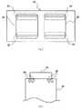
図1は、清浄空間保持装置の基本構成を示す側面図、図2は、清浄空間保持装置の基本構成を示す正面図である。
これらの図に示すように、清浄空間保持装置は、フォトマスク基板などの基板を清浄な空間に収納する収納装置や、基板を清浄な空間に収納して搬送する搬送台車として機能するように、収納体10、気流発生手段20、排気手段30及び車輪40を備えて構成されている。
【0021】
収納体10は、箱状に枠組みされたフレーム11を有し、このフレーム11によって形成される四つの側面のうち、対向する二つの側面が開放部12となり、他の側面が遮蔽面となっている。開放部12は、基板Kの出し入れ口であり、その左右両縁部には、開放部12を開閉する両開き状の扉13がヒンジ13aを介して取り付けられている。また、扉13及び遮蔽面を覆う壁板14は、透光性の板材からなり、扉13を閉じた状態でも、収納体10の内部が目視可能となっている。
なお、開放部12の数は、二つに限らず、一つ又は三つ以上であってもよい。また、開放部12は、収納体10の側面全体に形成することなく、側面の一部に形成してもよい。
【0022】
収納体10の内部には、基板Kを保持する基板保持具15が設けられている。基板保持具15は、例えば、基板Kの隣接する二つの辺を下方から支える複数の支持部材15aを有しており、主表面が鉛直方向に沿い、かつ、辺が傾いた縦置き姿勢で基板Kを保持するように構成される。このように構成された基板保持具15は、サイズが異なる各種の基板Kを保持できるという利点がある。
【0023】
気流発生手段20は、収納体10の上部に設けられた清浄空気送風機であり、収納体10の内部空間に上方から清浄な空気を送り込んでいる。気流発生手段20が収納体10の内部空間に発生させる気流の速度は、通常、清浄空間保持装置が設置されるクリーンルームのダウンフロー(例えば、0.3m/sec)よりも速くなっており、例えば、0.6m/secに設定されている。
【0024】
排気手段30は、収納体10の底部に設けられ、気流発生手段20から内部空間へ送り込まれた空気を収納体10の下方へ排気している。排気手段30としては、様々な通気部材を用いることが可能であるが、強度やコストの点からパンチングメタルなどの多孔板で形成することが好ましい。
【0025】
車輪40は、収納体10の下面四隅に設けられ、清浄空間保持装置を移動自在に支持している。これにより、清浄空間保持装置は、基板Kを収納体10の内部空間に収納して、所望の場所へ搬送することが可能になる。また、収納体10の内部空間に収納された基板Kは、気流発生手段20から送り込まれる空気により清浄な状態に保たれるが、開放部12を開けた際には、図12に示した理由により収納体10の内部に外気が流れ込み、外気に含まれるパーティクルが基板Kに付着する可能性がある。
本発明の清浄空間保持装置(クリーンルームの床部及び天井部の一部を含む。)は、このような問題を解決するために、風向調整手段や外気流調整手段を備えている。
【0026】
風向調整手段は、開放部12付近の気流を収納体10の外側へ方向付けるように構成される。収納体10の外側へ方向付けられた気流は、開放部12から外方へ吹き出す気流となり、開放部12からの外気の流入を抑制することになる。これにより、収納体10の内部空間を清浄な状態に保持し、基板Kに対するパーティクルの付着を防止することが可能になる。
【0027】
また、外気流調整手段は、収納体10の外側上方(クリーンルームの天井部)に設けられ、開放部12の外側付近における気流の速度及び/又は向きを調整するように構成される。つまり、外気流調整手段によって、開放部12の外側付近における気流の速度を速くしたり、開放部12の外側付近における気流の向きを整えることにより、開放部12からの外気の流れ込みを効果的に抑制することが可能になる。
以下、風向調整手段や外気流調整手段を備える清浄空間保持装置の各種実施形態について説明する。
【0028】
[第一実施形態]
まず、風向調整手段として第一の風向ガイド部材のみを備える清浄空間保持装置の実施形態について、図3〜図5を参照して説明する。
図3は、清浄空間保持装置の第一実施形態を示す概略正面図、図4(a)は、風向調整板の配置を示す平面図、図4(b)は、風向調整板の配置を示す正面図、図5は、風向板ユニットを示す斜視図である。
【0029】
これらの図に示すように、第一実施形態の清浄空間保持装置は、第一の風向ガイド部材として、片側二枚、全体で四枚の風向調整板50を備えている。この風向調整板50は、気流発生手段20から開放部12付近へ送り込まれる空気の流れを、収納体10の外側へ方向付けるように、収納体10の内部上方に設けられている。このような風向調整板50を備えれば、特に、開放部12の上側領域において外気の流れ込みを効果的に抑制することが可能になる。また、開放部12の高さ寸法が小さい清浄空間保持装置では、後述する第二の方向ガイド部材や外気流調整手段を設けることなく、上記の風向調整板50を設けるだけで、十分な外気流入防止効果を発揮することができる。
【0030】
本実施形態の風向調整板50は、樹脂などの板状部材からなり、気流発生手段20の直下位置で、かつ、開放部12の上端部に沿う位置に配置されている。風向調整板50の取付角度は、気流発生手段20から開放部12付近に送り込まれる空気の流れを、収納体10の外側へ方向付けられる角度(例えば、30〜50deg)であればよいが、取付角度を調整可能とし、状況に応じて適宜調整できるようにすることもできる。また、図4に示すように、複数の風向調整板50を並列状に配置するようにすれば、収納体10の外側へ吹き出す風量を増加させ、外気流入防止効果を高めることができる。
【0031】
図4は、複数の風向調整板50を並列状に備える風向板ユニット51を示している。この風向板ユニット51は、二枚の風向調整板50と、その両端部から突出する支軸50aを回動自在に支持する一対の取り付け板52とからなり、あらかじめユニットとして組み立てられた後、収納体10の上部に取り付けられる。これにより、風向調整板50の取付作業を簡略化することが可能になる。また、風向板ユニット51では、風向調整板50が回動自在に支持されているため、風向調整板50の角度を任意に調整することができる。風向調整板50を任意の角度で固定するための手段としては、風向調整板50の端部を貫通して取り付け板52に螺入されるビスなどが挙られる。
なお、風向調整板50は、二枚に限られるものではなく三枚以上あるいは、一枚であってもよい。また、風向調整板50は、収納体10の開放部側のみに設けてもよい。
【0032】
[第二実施形態]
つぎに、風向調整手段として第一及び第二の風向ガイド部材を備える清浄空間保持装置の実施形態について、図6及び図7を参照して説明する。
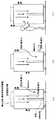
図6は、清浄空間保持装置の第二実施形態を示す概略正面図、図7は、グレーチングの配置を示す平面図である。
【0033】
これらの図に示すように、第二実施形態の清浄空間保持装置は、第一の風向ガイド部材として前述の風向調整板50を備えるだけでなく、第二の風向ガイド部材を備える。第二の風向ガイド部材は、収納体10の下方への排気を許容する排気領域と、収納体10の下方への排気を遮蔽する遮蔽領域とを有し、遮蔽領域から排気領域への気流の流れにより、開放部12付近の気流を収納体10の外側へ方向付けるように構成されている。
【0034】
このように第一及び第二の風向ガイド部材を備える清浄空間保持装置では、第一の風向ガイド部材によって、開放部12の上側領域における外気の流れ込みを抑制しながら、第二の風向ガイド部材によって、開放部12の下側領域における外気の流れ込みを抑制することができるため、収納体10内部の清浄度をさらに高めることが可能になる。
【0035】
本実施形態における第二の風向ガイド部材は、クリーンルームの床面を形成する二種類のグレーチング60、61を利用して構成される。一方のグレーチング60は、排気孔のない遮蔽グレーチングであり、清浄空間保持装置が所定の基板出し入れ位置にあるとき、清浄空間保持装置の下方に位置するように敷設される。また、他方のグレーチング61は、多数の排気孔が形成され、床面下方への排気が可能な排気グレーチングであり、清浄空間保持装置が所定の基板出し入れ位置にあるとき、清浄空間保持装置の周囲下方に位置するように敷設される。
【0036】
上記のように構成された第二の風向ガイド部材によれば、開放部12を開いたとき、収納体10の下方へ排気されるべき空気の流れが、排気グレーチング61側へ方向付けられるので、開放部12の下側領域において外方へ吹き出すような気流が発生し、外気の流入を抑制することが可能になる。
【0037】
[第三実施形態]
つぎに、第二の風向ガイド部材として傾斜板70を備える清浄空間保持装置の実施形態について、図8〜図10を参照して説明する。
図8は、清浄空間保持装置の第三実施形態を示す概略正面図、図9(a)は、傾斜板の平面図、図9(b)は、傾斜板の配置を示す正面図、図10は、傾斜板の斜視図である。
【0038】
これらの図に示すように、第三実施形態の清浄空間保持装置は、第二の風向ガイド部材としての傾斜板70を、収納体10の内部下方に備える。傾斜板70は、収納体10の下方への排気を許容する排気領域と、収納体10の下方への排気を遮蔽する遮蔽領域とを有し、遮蔽領域から排気領域への気流の流れにより、開放部12付近の気流を収納体10の外側へ方向付ける点では前記実施形態のものと同様であるが、収納体10の内部下方で風向調整を行うことにより、前記実施形態よりも優れた外気流入防止効果が得られる。
また、傾斜板70の排気領域は、排気手段30を兼ねることが可能であるため、部材の兼用化により、部品点数を削減できるだけでなく、装置の構造を簡略化できるという利点がある。
【0039】
傾斜板70は、排気領域のみに排気孔70a、70bを有するパンチングメタルなどで形成され、遮蔽領域より排気領域が低位となる傾斜姿勢で収納体10の内部下方に配置される。これにより、遮蔽領域から排気領域への気流の流れを促進し、開放部12の下側領域における外気の流れ込みを効果的に抑制することが可能になる。なお、本実施形態の清浄空間保持装置は、二つの開放部12を備えるため、傾斜板70を二枚とし、基板Kの下端部支持位置近傍が山頂となり、かつ、開放部12の下端部が山裾となるように、支持部材71を介して山形状に取り付けられている。
【0040】
また、傾斜板70の排気孔70a、70bは、図9や図10に示すように、遮蔽領域から外側に向けて、連続的又は段階的に開口率が大きくなるように形成されている。図9に示す例では、外側ほど排気孔70a、70bの数を増やすことにより開口率を変化させ、また、図10に示す例では、外側の排気孔70bほど孔径を大きくすることにより開口率を変化させている。
このように構成された傾斜板70によれば、外側ほど気流の速度が速くなるため、風速が速い方に気流が引かれる現象を利用し、遮蔽領域から排気領域への気流の流れを促進することができる。しかも、連続的又は段階的に開口率を大きくすることにより、気流の流れを円滑にし、気流の乱れによる外気の流入を防止できる利点がある。
【0041】
[第四実施形態]
つぎに、第一の風向ガイド部材、第二の風向ガイド部材及び外気流調整手段を備える清浄空間保持装置の実施例について、図11を参照して説明する。
図11は、清浄空間保持装置の第四実施形態を示す概略正面図である。
この図に示すように、第四実施形態の清浄空間保持装置は、前述した外気流調整手段としてカーテン80を備える。カーテン80は、例えば、塩化ビニールなどで形成されており、清浄空間保持装置が所定の基板出し入れ位置にあるとき、収納体10の外側上方を囲むように、クリーンルームの天井部に吊り下げ状に設けられる。
【0042】
上記のように設けられたカーテン80は、開放部12の外側付近における気流の速度及び/又は向きを調整することができる。例えば、カーテン80により、開放部12の外側付近における外気周の速度を速くし(例えば、0.5m/sec)、かつ、開放部12の外側付近における気流の向きを整えれば、開放部12からの外気の流れ込みを効果的に抑制することが可能になる。また、本実施形態のように、第一の風向ガイド部材や第二の風向ガイド部材を併用すれば、外気流入防止効果を更に高めることができる。
【0043】
[フォトマスクの搬送方法]
つぎに、本発明に係るフォトマスク基板の搬送方法について説明する。
まず、従来と同様の方法を用いてフォトマスク基板を製造した後、洗浄装置を用いて洗浄を行った。その後、本発明の清浄空間保持装置を用いて、洗浄後のフォトマスク基板を異物検査装置まで搬送した。搬送されたフォトマスク基板を人手により取り出し、異物検査装置にセットして異物検査を行った。その結果、所定の欠陥レベルを越え、再洗浄を要する欠陥が、従来より減少した。その後、異物検査の洗浄度が保たれたまま、ペリクルの装着を行うことができた。
【0044】
【発明の効果】
以上のように、本発明によれば、清浄空間保持装置において、収納体の開放部から外気が入り込むことを抑えることによって、収納体の内部空間を清浄な状態に保持し、基板などの物体に対するパーティクルの付着を防止することができる。
また、フォトマスク基板の搬送方法において、上記清浄空間保持装置を用いて、フォトマスク基板を搬送することにより、フォトマスク基板に対するパーティクルの付着を防止することができる。
【図面の簡単な説明】
【図1】清浄空間保持装置の基本構成を示す側面図である。
【図2】清浄空間保持装置の基本構成を示す正面図である。
【図3】清浄空間保持装置の第一実施形態を示す概略正面図である。
【図4】(a)は、風向調整板の配置を示す平面図、(b)は、風向調整板の配置を示す正面図である。
【図5】風向板ユニットを示す斜視図である。
【図6】清浄空間保持装置の第二実施形態を示す概略正面図である。
【図7】グレーチングの配置を示す平面図である。
【図8】清浄空間保持装置の第三実施形態を示す概略正面図である。
【図9】(a)は、傾斜板の平面図、(b)は、傾斜板の配置を示す正面図である。
【図10】傾斜板の斜視図である。
【図11】清浄空間保持装置の第四実施形態を示す概略正面図である。
【図12】(a)〜(c)は、従来の問題点を示す説明図である。
【符号の説明】
K 基板
10 収納体
12 開放部
13 扉
15 基板保持具
20 気流発生手段
30 排気手段
40 車輪
50 風向調整板
51 風向板ユニット
60 遮蔽グレーチング
61 排気グレーチング
70 傾斜板
70a 排気孔
70b 排気孔
80 カーテン[0001]
TECHNICAL FIELD OF THE INVENTION
The present invention relates to a clean space holding device used for transferring and storing a photomask substrate and the like, and further relates to a photomask transferring method using the clean space holding device.
[0002]
[Prior art]
2. Description of the Related Art A semiconductor substrate, a liquid crystal display panel substrate, a photomask used for the production thereof, and the like are produced through many steps.
For example, for a photomask, a step of forming a chromium film on a light-transmitting substrate such as a quartz glass substrate by a film forming apparatus, a step of applying a resist film on a chromium film by a resist coater, a laser drawing apparatus, A step of drawing a predetermined pattern on the resist film by using an electron beam drawing apparatus, a step of performing development processing by using a resist developing apparatus, a step of etching the chromium film by using an etching apparatus, and a step of removing the resist by using a resist removing apparatus. A process of cleaning the substrate with a cleaning device, a process of performing a pattern inspection of a light-shielding film pattern with a defect inspection device, and, if necessary, a process of correcting the light-shielding film pattern with a pattern correction device. . Finally, after finishing cleaning is performed by the cleaning device and foreign material inspection is performed by the foreign material inspection device, the pellicle is mounted and shipped as a photomask.
[0003]
As described above, photomasks manufactured through many steps frequently move between apparatuses used in each step. In this case, not only are the substrates safely transported, but also particles It is also required to prevent such adhesion.
In particular, since a liquid crystal panel substrate and a photomask for manufacturing a liquid crystal panel include a large-sized substrate having a side exceeding 300 mm, it is necessary to use a transport trolley for transporting the substrate for safety. In recent years, the size of these substrates has been increasing, and the weight of the substrates has increased accordingly.
[0004]
Conventionally, as a transport trolley capable of meeting the above requirements, a substrate being transported is stored in a space having a higher degree of cleanliness than a clean room in which the manufacturing is performed, thereby protecting the substrate from particle adhesion. (For example, see Patent Document 1).
For example, a transport trolley (substrate transport device) disclosed in Patent Literature 1 includes an airflow generating unit (clean air blower) that feeds clean air from above a storage body (box) that stores a substrate, and the airflow generating unit. By providing exhaust means (punching metal) for exhausting the sent air downward, the internal space of the storage body is kept in a clean state.
[0005]
[Patent Document 1]
JP-A-7-2463 (page 1, FIG. 1)
[0006]
[Problems to be solved by the invention]
However, although the transport trolley disclosed in Patent Document 1 creates a space with high cleanliness by the airflow generating means, the airflow outside the storage body enters the storage body and is still included in the external airflow. There is a problem that particles adhere to the substrate.
[0007]
In addition, in order to increase the cleanliness inside the storage body, it is conceivable to provide a door at an opening serving as a substrate entrance and open the opening only when the substrate is taken in and out, but the present inventors investigated. However, it has been found that even when the opening time of the opening is short, the airflow outside the storage body enters the storage body, and the cleanliness of the internal space is reduced.
The reasons are considered as follows.
(1) When the door is opened, an airflow outside the housing flows into the housing due to a difference in airflow velocity inside and outside the housing (see FIG. 12A).
(2) When the door is opened, the air outside the storage body is pushed into the storage body by the lateral airflow outside the storage body (see FIG. 12B).
(3) When a person's hand is inserted into the housing, air outside the housing is sent into the housing by the inserted hand (see FIG. 12C).
[0008]
The present invention has been made in view of the above circumstances, and suppresses the outside air from entering the open portion of the storage body, thereby keeping the internal space of the storage body in a clean state, and preventing particles from flowing to an object such as a substrate. A first object is to provide a clean space holding device capable of preventing adhesion.
It is a second object of the present invention to provide a method for transporting a photomask substrate, which can prevent particles from adhering to the photomask substrate by transporting the photomask substrate using the clean space holding device.
[0009]
[Means for Solving the Problems]
In order to achieve the above object, the clean space holding device of the present invention is a clean space holding device that has a storage body in which an object is stored and that holds the internal space of the storage body in a clean state, An opening formed on the side surface of the storage body and serving as an access port for the object, an airflow generating means for sending clean air from above the storage body, and air supplied from the airflow generation means for the storage body. It is configured to include an exhaust unit that exhausts downward, and a wind direction adjusting unit that directs an airflow near the opening to the outside of the housing.
If the clean space holding device is configured in this way, it is possible to suppress the outside air from entering the inside of the housing from the opening by directing the airflow near the opening toward the outside of the housing. Thereby, the internal space of the storage body can be kept clean, and adhesion of particles to an object such as a substrate can be prevented.
[0010]
Further, in the clean space holding device of the present invention, the wind direction adjusting means is provided above the inside of the storage body, and the flow of air sent from the airflow generation means to the vicinity of the open portion is directed to the outside of the storage body. It is configured to include a first wind direction guide member for directing.
With this configuration of the clean space holding device, it is possible to effectively suppress the flow of outside air particularly in the upper region of the open portion, and increase the cleanliness inside the storage body.
[0011]
Further, in the clean space holding device according to the present invention, the wind direction adjusting means has an exhaust region that allows exhaust to the lower part of the housing, and a shield region that shields exhaust to the lower part of the housing, And a second airflow direction guide member for directing the airflow near the opening to the outside of the housing by the flow of the airflow from the air to the exhaust region.
With this configuration of the clean space holding device, the first airflow direction guide member suppresses the flow of outside air in the upper region of the open portion, and the second airflow direction guide member allows the outside air in the lower region of the open portion. , It is possible to further increase the cleanliness inside the storage body.
[0012]
Further, in the clean space holding device according to the present invention, the exhaust region also serves as the exhaust unit.
If the clean space holding device is configured in this way, the number of components can be reduced by using the same member, and the structure of the device can be simplified.
[0013]
Further, in the clean space holding device of the present invention, the second wind direction guide member is formed by an inclined plate in which the exhaust area is lower than the shielding area.
With this configuration of the clean space holding device, the inclination of the inclined plate promotes the flow of airflow from the shielding region to the exhaust region, and effectively suppresses the inflow of outside air in the lower region of the opening. it can.
[0014]
Further, the clean space holding device of the present invention is configured such that the exhaust region has an exhaust hole group whose opening ratio increases continuously or stepwise from the shielding region toward the outside.
If the clean space holding device is configured in this way, the speed of the air flow becomes higher toward the outside, so that the flow of the air flow is drawn toward the faster wind speed, thereby promoting the flow of the air flow from the shielding region to the exhaust region. Can be. In addition, by increasing the aperture ratio continuously or stepwise, the flow of the airflow can be made smooth, and the inflow of the outside air due to the turbulence of the airflow can be prevented.
[0015]
Further, the clean space holding device of the present invention is configured such that an external airflow adjusting means for adjusting the speed and / or direction of the airflow near the outside of the opening is provided above the outside of the housing.
If the clean space holding device is configured in this manner, the speed of the airflow near the outside of the open portion can be increased, and the direction of the airflow near the outside of the open portion can be adjusted. Inflow of outside air can be effectively suppressed.
[0016]
Further, in the clean space holding device of the present invention, the storage body includes a door that opens and closes the opening.
When the clean space holding device is configured in this manner, the internal space of the storage body can be held in a clean state by shielding the open portion with the door except when an object such as a substrate is taken in and out.
[0017]
Further, in the clean space holding device of the present invention, the object is constituted by a photomask substrate.
With this configuration of the clean space holding device, it is possible to keep the internal space of the storage body in a clean state and prevent particles from adhering to the photomask substrate.
[0018]
In order to achieve the above object, a method for transporting a photomask substrate according to the present invention is a method for transporting a photomask substrate, wherein the photomask substrate is stored in a storage body of the clean space holding device. There is a method of carrying.
With such a method of transporting the photomask substrate, it is possible to keep the internal space of the housing clean when transporting the photomask substrate, and prevent particles from adhering to the photomask substrate.
[0019]
BEST MODE FOR CARRYING OUT THE INVENTION
Hereinafter, embodiments of the present invention will be described with reference to the drawings.
[Clean space holding device]
First, the basic configuration of the clean space holding device according to the present invention will be described with reference to FIGS.
[0020]
FIG. 1 is a side view showing the basic configuration of the clean space holding device, and FIG. 2 is a front view showing the basic configuration of the clean space holding device.
As shown in these figures, the clean space holding device functions as a storage device that stores a substrate such as a photomask substrate in a clean space, or as a transport trolley that stores and transports a substrate in a clean space. It comprises a
[0021]
The
The number of the opening
[0022]
A substrate holder 15 for holding the substrate K is provided inside the
[0023]
The airflow generating means 20 is a clean air blower provided at an upper portion of the
[0024]
The exhaust means 30 is provided at the bottom of the
[0025]
The
The clean space holding device (including a part of the floor and the ceiling of the clean room) of the present invention includes a wind direction adjusting unit and an outside air flow adjusting unit in order to solve such a problem.
[0026]
The wind direction adjusting means is configured to direct the airflow near the
[0027]
The outside airflow adjusting means is provided above the outside of the housing 10 (the ceiling of the clean room), and is configured to adjust the speed and / or direction of the airflow near the outside of the
Hereinafter, various embodiments of a clean space holding device including a wind direction adjusting unit and an outside air flow adjusting unit will be described.
[0028]
[First embodiment]
First, an embodiment of a clean space holding device including only a first wind direction guide member as a wind direction adjusting unit will be described with reference to FIGS.
FIG. 3 is a schematic front view showing the first embodiment of the clean space holding device, FIG. 4 (a) is a plan view showing an arrangement of a wind direction adjusting plate, and FIG. 4 (b) shows an arrangement of a wind direction adjusting plate. FIG. 5 is a perspective view showing a wind direction plate unit.
[0029]
As shown in these figures, the clean space holding device of the first embodiment includes two wind
[0030]
The wind
[0031]
FIG. 4 shows a wind direction plate unit 51 having a plurality of wind
The number of wind
[0032]
[Second embodiment]
Next, an embodiment of a clean space holding device including first and second wind direction guide members as wind direction adjusting means will be described with reference to FIGS.
FIG. 6 is a schematic front view showing a second embodiment of the clean space holding device, and FIG. 7 is a plan view showing an arrangement of gratings.
[0033]
As shown in these drawings, the clean space holding device of the second embodiment includes not only the above-described wind
[0034]
As described above, in the clean space holding device including the first and second wind direction guide members, the first wind direction guide member suppresses the inflow of outside air in the upper region of the
[0035]
The second wind direction guide member in the present embodiment is configured using two types of
[0036]
According to the second wind direction guide member configured as described above, when the opening
[0037]
[Third embodiment]
Next, an embodiment of a clean space holding device including an
FIG. 8 is a schematic front view showing a third embodiment of the clean space holding device, FIG. 9 (a) is a plan view of the inclined plate, FIG. 9 (b) is a front view showing the arrangement of the inclined plate, FIG. FIG. 4 is a perspective view of an inclined plate.
[0038]
As shown in these drawings, the clean space holding device of the third embodiment includes an
Further, since the exhaust area of the
[0039]
The
[0040]
Further, as shown in FIGS. 9 and 10, the exhaust holes 70a and 70b of the
According to the
[0041]
[Fourth embodiment]
Next, an embodiment of a clean space holding device including a first wind direction guide member, a second wind direction guide member, and an outside air flow adjusting unit will be described with reference to FIG.
FIG. 11 is a schematic front view showing a fourth embodiment of the clean space holding device.
As shown in this figure, the clean space holding device of the fourth embodiment includes a
[0042]
The
[0043]
[Photomask transport method]
Next, a method for transporting a photomask substrate according to the present invention will be described.
First, a photomask substrate was manufactured using a method similar to the conventional method, and then cleaned using a cleaning apparatus. Thereafter, the cleaned photomask substrate was transported to the foreign matter inspection device using the clean space holding device of the present invention. The transported photomask substrate was manually taken out and set in a foreign matter inspection device to perform foreign matter inspection. As a result, the number of defects exceeding a predetermined defect level and requiring recleaning has been reduced as compared with the conventional case. Thereafter, the pellicle could be mounted while the cleaning degree of the foreign substance inspection was maintained.
[0044]
【The invention's effect】
As described above, according to the present invention, in the clean space holding device, the internal space of the storage body is kept in a clean state by suppressing the outside air from entering the open portion of the storage body, and the space for the object such as the substrate is prevented. Particle adhesion can be prevented.
Further, in the method for transporting a photomask substrate, the adhesion of particles to the photomask substrate can be prevented by transporting the photomask substrate using the clean space holding device.
[Brief description of the drawings]
FIG. 1 is a side view showing a basic configuration of a clean space holding device.
FIG. 2 is a front view showing a basic configuration of the clean space holding device.
FIG. 3 is a schematic front view showing the first embodiment of the clean space holding device.
FIG. 4A is a plan view showing an arrangement of a wind direction adjusting plate, and FIG. 4B is a front view showing an arrangement of a wind direction adjusting plate.
FIG. 5 is a perspective view showing a wind direction unit.
FIG. 6 is a schematic front view showing a second embodiment of the clean space holding device.
FIG. 7 is a plan view showing an arrangement of gratings.
FIG. 8 is a schematic front view showing a third embodiment of the clean space holding device.
FIG. 9A is a plan view of an inclined plate, and FIG. 9B is a front view showing an arrangement of the inclined plate.
FIG. 10 is a perspective view of an inclined plate.
FIG. 11 is a schematic front view showing a fourth embodiment of the clean space holding device.
FIGS. 12A to 12C are explanatory diagrams showing a conventional problem.
[Explanation of symbols]
Claims (10)
Translated fromJapanese前記収納体の側面部に形成され、前記物体の出し入れ口となる開放部と、
前記収納体の上方から清浄な空気を送り込む気流発生手段と、
前記気流発生手段から送り込まれた空気を前記収納体の下方へ排気する排気手段と、
前記開放部付近の気流を前記収納体の外側へ方向付ける風向調整手段と、
を備えることを特徴とする清浄空間保持装置。A clean space holding device having a storage body in which an object is stored, and holding an internal space of the storage body in a clean state,
An opening formed on a side surface of the storage body and serving as an access port for the object,
Airflow generating means for sending clean air from above the storage body,
Exhaust means for exhausting the air sent from the airflow generating means to below the housing,
Wind direction adjusting means for directing the airflow near the opening to the outside of the housing,
A clean space holding device comprising:
前記フォトマスク基板を、請求項1〜9のいずれかに記載した清浄空間保持装置の収納体に収納して搬送することを特徴とするフォトマスク基板の搬送方法。A method for transporting a photomask substrate, comprising:
A method for transporting a photomask substrate, comprising: transporting the photomask substrate while accommodating the photomask substrate in a storage body of the clean space holding device according to claim 1.
Priority Applications (1)
| Application Number | Priority Date | Filing Date | Title |
|---|---|---|---|
| JP2003125685AJP4278426B2 (en) | 2003-04-30 | 2003-04-30 | Clean space holding device, photomask substrate transfer device, and photomask substrate storage and holding method |
Applications Claiming Priority (1)
| Application Number | Priority Date | Filing Date | Title |
|---|---|---|---|
| JP2003125685AJP4278426B2 (en) | 2003-04-30 | 2003-04-30 | Clean space holding device, photomask substrate transfer device, and photomask substrate storage and holding method |
Publications (2)
| Publication Number | Publication Date |
|---|---|
| JP2004335552Atrue JP2004335552A (en) | 2004-11-25 |
| JP4278426B2 JP4278426B2 (en) | 2009-06-17 |
Family
ID=33502871
Family Applications (1)
| Application Number | Title | Priority Date | Filing Date |
|---|---|---|---|
| JP2003125685AExpired - LifetimeJP4278426B2 (en) | 2003-04-30 | 2003-04-30 | Clean space holding device, photomask substrate transfer device, and photomask substrate storage and holding method |
Country Status (1)
| Country | Link |
|---|---|
| JP (1) | JP4278426B2 (en) |
Cited By (3)
| Publication number | Priority date | Publication date | Assignee | Title |
|---|---|---|---|---|
| JP2009147163A (en)* | 2007-12-14 | 2009-07-02 | Hitachi Plant Technologies Ltd | Transport cart |
| JP2009289867A (en)* | 2008-05-28 | 2009-12-10 | Shin-Etsu Chemical Co Ltd | Conveying device |
| JP2011040736A (en)* | 2009-07-27 | 2011-02-24 | Asml Netherlands Bv | Imprint lithography apparatus and method |
- 2003
- 2003-04-30JPJP2003125685Apatent/JP4278426B2/ennot_activeExpired - Lifetime
Cited By (4)
| Publication number | Priority date | Publication date | Assignee | Title |
|---|---|---|---|---|
| JP2009147163A (en)* | 2007-12-14 | 2009-07-02 | Hitachi Plant Technologies Ltd | Transport cart |
| JP2009289867A (en)* | 2008-05-28 | 2009-12-10 | Shin-Etsu Chemical Co Ltd | Conveying device |
| JP2011040736A (en)* | 2009-07-27 | 2011-02-24 | Asml Netherlands Bv | Imprint lithography apparatus and method |
| US9547234B2 (en) | 2009-07-27 | 2017-01-17 | Asml Netherlands B.V. | Imprint lithography apparatus and method |
Also Published As
| Publication number | Publication date |
|---|---|
| JP4278426B2 (en) | 2009-06-17 |
Similar Documents
| Publication | Publication Date | Title |
|---|---|---|
| JP5398595B2 (en) | Board storage device | |
| JP4354675B2 (en) | Thin plate electronic component clean transfer device and thin plate electronic product manufacturing system | |
| KR20020047196A (en) | Wafer atmospheric transport module having a controlled mini-environment | |
| TWI417649B (en) | Reticle carrying device, exposure device, reticle carrying method, and reticle processing method | |
| JP2003080144A (en) | Coating film forming apparatus | |
| US6347990B1 (en) | Microelectronic fabrication system cleaning methods and systems that maintain higher air pressure in a process area than in a transfer area | |
| JP2006352099A (en) | Substrate inspection device | |
| JP2021022719A (en) | Apparatus for storing substrate and method of manufacturing apparatus | |
| JP2013160833A (en) | Polarized light illumination device | |
| JP4278426B2 (en) | Clean space holding device, photomask substrate transfer device, and photomask substrate storage and holding method | |
| WO2013084373A1 (en) | X-ray inspection apparatus | |
| TWI618899B (en) | Substrate transporting device, substrate treating apparatus, and substrate transporting method | |
| TWI760133B (en) | Photomask cleaning apparatus and method | |
| US12298664B2 (en) | Advanced load port for photolithography mask inspection tool | |
| JP2006242419A (en) | Clean booth and work system using the clean booth | |
| TWI648812B (en) | Mini environment device | |
| JP2009032756A (en) | Semiconductor manufacturing apparatus | |
| TWM505053U (en) | Mask dustproof frame structure | |
| TW471008B (en) | Substrate transport device | |
| KR101160535B1 (en) | Apparatus for treating substrates | |
| KR101179819B1 (en) | Apparatus for treating substrate | |
| TWI566033B (en) | Mask dustproof frame structure | |
| KR102534203B1 (en) | substrate handling system | |
| JP3741178B2 (en) | X-ray reduction exposure apparatus and X-ray projection exposure method | |
| JPWO2016153051A1 (en) | Inspection device |
Legal Events
| Date | Code | Title | Description |
|---|---|---|---|
| A621 | Written request for application examination | Free format text:JAPANESE INTERMEDIATE CODE: A621 Effective date:20060209 | |
| A977 | Report on retrieval | Free format text:JAPANESE INTERMEDIATE CODE: A971007 Effective date:20081017 | |
| A131 | Notification of reasons for refusal | Free format text:JAPANESE INTERMEDIATE CODE: A131 Effective date:20081021 | |
| A521 | Request for written amendment filed | Free format text:JAPANESE INTERMEDIATE CODE: A523 Effective date:20081216 | |
| TRDD | Decision of grant or rejection written | ||
| A01 | Written decision to grant a patent or to grant a registration (utility model) | Free format text:JAPANESE INTERMEDIATE CODE: A01 Effective date:20090310 | |
| A01 | Written decision to grant a patent or to grant a registration (utility model) | Free format text:JAPANESE INTERMEDIATE CODE: A01 | |
| A61 | First payment of annual fees (during grant procedure) | Free format text:JAPANESE INTERMEDIATE CODE: A61 Effective date:20090310 | |
| FPAY | Renewal fee payment (event date is renewal date of database) | Free format text:PAYMENT UNTIL: 20120319 Year of fee payment:3 | |
| R150 | Certificate of patent or registration of utility model | Ref document number:4278426 Country of ref document:JP Free format text:JAPANESE INTERMEDIATE CODE: R150 Free format text:JAPANESE INTERMEDIATE CODE: R150 | |
| FPAY | Renewal fee payment (event date is renewal date of database) | Free format text:PAYMENT UNTIL: 20120319 Year of fee payment:3 | |
| FPAY | Renewal fee payment (event date is renewal date of database) | Free format text:PAYMENT UNTIL: 20130319 Year of fee payment:4 | |
| R250 | Receipt of annual fees | Free format text:JAPANESE INTERMEDIATE CODE: R250 | |
| FPAY | Renewal fee payment (event date is renewal date of database) | Free format text:PAYMENT UNTIL: 20130319 Year of fee payment:4 | |
| FPAY | Renewal fee payment (event date is renewal date of database) | Free format text:PAYMENT UNTIL: 20140319 Year of fee payment:5 | |
| R250 | Receipt of annual fees | Free format text:JAPANESE INTERMEDIATE CODE: R250 | |
| R250 | Receipt of annual fees | Free format text:JAPANESE INTERMEDIATE CODE: R250 | |
| R250 | Receipt of annual fees | Free format text:JAPANESE INTERMEDIATE CODE: R250 | |
| R250 | Receipt of annual fees | Free format text:JAPANESE INTERMEDIATE CODE: R250 | |
| S531 | Written request for registration of change of domicile | Free format text:JAPANESE INTERMEDIATE CODE: R313531 | |
| R350 | Written notification of registration of transfer | Free format text:JAPANESE INTERMEDIATE CODE: R350 | |
| R250 | Receipt of annual fees | Free format text:JAPANESE INTERMEDIATE CODE: R250 | |
| R250 | Receipt of annual fees | Free format text:JAPANESE INTERMEDIATE CODE: R250 | |
| R250 | Receipt of annual fees | Free format text:JAPANESE INTERMEDIATE CODE: R250 | |
| R250 | Receipt of annual fees | Free format text:JAPANESE INTERMEDIATE CODE: R250 | |
| R250 | Receipt of annual fees | Free format text:JAPANESE INTERMEDIATE CODE: R250 | |
| R250 | Receipt of annual fees | Free format text:JAPANESE INTERMEDIATE CODE: R250 | |
| R250 | Receipt of annual fees | Free format text:JAPANESE INTERMEDIATE CODE: R250 | |
| EXPY | Cancellation because of completion of term |