JP2004334752A - Information processing apparatus, maintenance management method and program, and computer-readable storage medium - Google Patents
Information processing apparatus, maintenance management method and program, and computer-readable storage mediumDownload PDFInfo
- Publication number
- JP2004334752A JP2004334752AJP2003132832AJP2003132832AJP2004334752AJP 2004334752 AJP2004334752 AJP 2004334752AJP 2003132832 AJP2003132832 AJP 2003132832AJP 2003132832 AJP2003132832 AJP 2003132832AJP 2004334752 AJP2004334752 AJP 2004334752A
- Authority
- JP
- Japan
- Prior art keywords
- counter
- image forming
- forming apparatus
- counter value
- information
- Prior art date
- Legal status (The legal status is an assumption and is not a legal conclusion. Google has not performed a legal analysis and makes no representation as to the accuracy of the status listed.)
- Granted
Links
Images


Classifications
- G—PHYSICS
- G03—PHOTOGRAPHY; CINEMATOGRAPHY; ANALOGOUS TECHNIQUES USING WAVES OTHER THAN OPTICAL WAVES; ELECTROGRAPHY; HOLOGRAPHY
- G03G—ELECTROGRAPHY; ELECTROPHOTOGRAPHY; MAGNETOGRAPHY
- G03G15/00—Apparatus for electrographic processes using a charge pattern
- G03G15/50—Machine control of apparatus for electrographic processes using a charge pattern, e.g. regulating differents parts of the machine, multimode copiers, microprocessor control
- G03G15/5075—Remote control machines, e.g. by a host
- G03G15/5079—Remote control machines, e.g. by a host for maintenance
- G—PHYSICS
- G03—PHOTOGRAPHY; CINEMATOGRAPHY; ANALOGOUS TECHNIQUES USING WAVES OTHER THAN OPTICAL WAVES; ELECTROGRAPHY; HOLOGRAPHY
- G03G—ELECTROGRAPHY; ELECTROPHOTOGRAPHY; MAGNETOGRAPHY
- G03G15/00—Apparatus for electrographic processes using a charge pattern
- G03G15/55—Self-diagnostics; Malfunction or lifetime display
Landscapes
- Engineering & Computer Science (AREA)
- Microelectronics & Electronic Packaging (AREA)
- Physics & Mathematics (AREA)
- General Physics & Mathematics (AREA)
- Accessory Devices And Overall Control Thereof (AREA)
- Control Or Security For Electrophotography (AREA)
Abstract
Translated fromJapaneseDescription
Translated fromJapanese【0001】
【発明の属する技術分野】
本願発明は、画像形成装置の外部において、画像形成装置の部品の使用履歴を管理する仕組みに関する。
【0002】
【従来の技術】
事務機器で利用される消耗部品は、あらかじめ寿命が想定されており、その寿命に対して消耗度を測るカウンタ値が予め想定された寿命基準値に達しているかどうかを目安にして、サービスマンが交換を行っている。
【0003】
また、遠隔にて、画像形成装置の部品のカウンタの値を取得し、部品の寿命にカウンタが達しているかどうかを判断し、寿命に達しようとしている部品はサービスマンが交換する作業を行っていた。
【0004】
特許文献1には、着脱可能なユニットの寿命を基準値と、ネットワークを介して定期的或いは所定のタイミングで遠隔に通知されてくるユニットの使用状況等のデータによりユニットの寿命を判断し、寿命と判断された場合には画像形成装置に通知をその旨の通知を行う印刷システムが知られている。
【0005】
一方、従来から知られている技術として、特許文献2には、交換パーツを備える複写装置において、前回交換されたパーツの寿命を鑑みて、使用実績に応じて補正された寿命基準を予測する画像形成装置が知られている。
【0006】
このように、画像形成装置において利用される各部品いついて、特許文献1のように遠隔における寿命の管理や、特許文献2に開示されるように、ユーザ毎に異なりうる部品の使用方法に即した部品の使用実績を管理し、寿命基準の目安にするような管理が重要となっている。
【0007】
【特許文献1】
特開平07−066885号公報
【特許文献2】
特開平01−123253号公報
【0008】
【発明が解決しようとする課題】
しかしながら、実際の部品の使用履歴を、遠隔の外部装置で管理するにあたって、部品が交換されてしまうと、例えばサービスマンがカウンタリセットボタンを押下するなど、何らかの方法で部品の使用状況のカウンタ(例えば印刷枚数カウンタ)がクリアされてしまい、画像形成装置におけるカウンタ値が大きくなったり小さくなったりして、部品の寿命履歴を正確に管理することが出来ないという問題点があった。
【0009】
これに対して、交換前の部品の使用状況のカウンタ値(使用履歴)を遠隔の外部装置に通知するよな仕組みを設けるという解決策も想定されるが、既にユーザ先で利用されている画像形成装置も含めて保守管理することを考慮すると、交換前の部品の使用状況のカウンタ値を遠隔の外部装置に通知する機能を備えないものも多数あり、総合的解決にはならないという問題点があった。
【0010】
本願発明は上記問題点を鑑みてなされたものであり、交換前の部品の使用状況のカウンタ値を遠隔の外部装置に通知する機能を備えない画像形成装置にも対応して部品の寿命を画像形成装置と通信可能な外部装置で管理することができる仕組みを提供することを目的とする。
【0011】
【課題を解決するための手段】
上記課題を解決するために、画像形成装置における部品の使用履歴を取得可能な情報処理装置において、画像形成装置における部品のカウンタ値の取得をし、取得したカウンタ値の大小関係を判定し、該判定によりカウンタ値が小さくなったと判定された場合には、交換前の部品を対象に最後に取得されたカウンタ値を交換前の部品の使用実績する仕組みを提供する。
【0012】
【発明の実施の形態】
以下、本発明の実施の形態を、図面を参照して説明する。
【0013】
[第1の実施の形態]
図1は、本発明に係る管理装置を含む遠隔監視システムの第1の実施の形態の全体構成を示す図である。
【0014】
本遠隔監視システムでは、センタ側管理サーバ6及び拠点側管理サーバ2が、一般的な情報処理装置によってそれぞれ構成され、インターネット等の通信回線8を介し、所定のプロトコル10によって互いに通信可能である。拠点側管理サーバ2及びセンタ側管理サーバ6は、例えばメールサーバやルータの機能を掌る部分として想定することができる。
【0015】
センタ側管理サーバ6と拠点側管理サーバ2とは、通信回線8を介して、所定のプロトコル10で接続されるが、不正アクセスを防ぐために、またファイアウォールを越すために、一般的なプロトコル(SMTP)や認証も設けるようにする。
【0016】
監視装置1が、ネットワーク9を介して画像形成装置3〜5及びパーソナルコンピュータ(以下「PC」という)12に接続され、画像形成装置3〜5及びPC12の稼動情報や障害情報(詳しくは後述)を収集すると共に、画像形成装置3〜5及びPC12の制御プログラムなどを更新する機能を備え、更に、収集した情報を、拠点側管理サーバ2を介してセンタ側管理サーバ6に転送する機能を備える。
【0017】
パーソナルコンピュータ(以下「PC」という)7がネットワークを介してセンタ側管理サーバ6に接続され、センタ側管理サーバ6のクライアントコンピュータとして動作する。PC7は各種情報処理を実行するとともに、センタ側管理サーバ6で収集された情報を共有することができる。
【0018】
なお図1では、監視装置1と拠点側管理サーバ2とが別体として設置され、またPC7とセンタ側管理サーバ6とが別体として設置されているが、監視装置1と拠点側管理サーバ2とを1つの装置にし、またPC7とセンタ側管理サーバ6とを1つの装置にしてもよい。これを、図1中において点線枠にて示す。
【0019】
なおまた、図1中には、監視装置1を1つしか図示しないが、実際には、複数の監視装置がネットワーク9に接続されるとともに、各監視装置によってそれぞれ監視される画像形成装置及びPCがネットワーク9に接続され、センタ側管理サーバ6が、それら複数の監視装置を一元的に管理する。複数の監視装置の各々が後述する各種処理/制御を実現する。
【0020】
図1中の、画像形成装置3〜5は、具体的にはプリンタ(電子写真方式及びインクジェット方式を含む)、ファクシミリ装置、スキャナ、プリンタ及びファクシミリ機能が統合的に設けられたデジタル複合機、プリントサーバなどのうちのいずれかである。
【0021】
図1中に不図示のPC12は、例えば、所定のアプリケーションデータをOS(Operating System)、プリンタドライバを介してPDL(Page Description Language)データに変換し、該PDLデータを画像形成装置3〜5のいずれかに送信する機能を備える。
【0022】
なお、監視装置1は、画像形成装置3〜5及びPC12からメンテナンス情報を収集する。メンテナンス情報は、稼動情報に少なくとも障害情報を含むものであり、稼動情報は、画像形成装置3〜5では、それら装置の状態、トナー残量、用紙サイズ毎の印刷枚数等であり、PC12では、PC12内のCPU及びメモリの稼動状況、有料アプリケーション使用状況等である。障害情報は、画像形成装置3〜5でのジャム情報やPC12での再起動回数情報等である。
【0023】
図2は、図1に示す監視装置1、PC12、PC7、拠点側管理サーバ2、センタ側管理サーバ6のハードウェアブロック構成図を示す図である。
【0024】
23のマウスおよび24のキーボードのインタフェースとCPU、ROM、RAM、HDD(ハードディスク)、25のモニタと接続されるCRTC(ビデオカード)および、拠点側ネットワーク25に接続するLANアダプタから構成される一般的なパーソナルコンピュータである。RAMやHDDには複数のデバイス各々から取得した各種部品の使用状況を示すカウンタ情報が保持される。
【0025】
図3は監視装置1によるデバイス障害監視処理を示すフローチャートである。監視装置1から拠点側管理サーバ2或いはセンタ側管理サーバ6(以下ホストと称する)或いはセンタ側クライアントPC7に対する情報送信は上記SMTPで行い、情報受信はPOP(Post Office Protocol)により行う場合について説明する。
【0026】
図3のステップS302では、監視装置1は監視対象のデバイスの障害情報を確認する障害情報確認プログラムを実行し、監視対象のデバイスそれぞれに関し、ステップS303〜ステップS307の処理を行うことにより、例えば1分間隔で障害情報の確認処理を行っている。先ずステップS302において、監視装置1はLAN9を介して監視対象のデバイスに対し障害情報を取得しに行く。次にステップS303において、障害情報を取得したかどうかを判定し、障害情報を取得したと判断した場合は、ステップS304に進む。
【0027】
ステップS304において、監視装置1はホストに対し、上記ステップS302において取得した障害情報を送信する。次にステップS305において、監視装置1はホストからの応答を待つ応答確認プログラムを起動する。一方、ステップS303において、上記ステップS302で障害情報を取得しなかったと判断した場合は、ステップS306に進む。ステップS306において、監視装置1は1分間隔で障害情報の確認を行うために、1分間待機する。
【0028】
ステップS308では、監視装置1は上記ステップS304でホストへ障害情報を送信した後、ステップS305で起動される応答確認プログラムを実行する。監視装置1から障害情報をホストが受け取った場合、受け取ったことを示す情報をホストから監視装置1宛に電子メール(以下メールと略称)で通知する仕組みとなっている。応答確認プログラムにおいては、監視装置1はステップS309〜ステップS311の処理を例えば30秒間隔で繰り返しながら、最高30分間ホストからの応答を待ち、その間に応答がなければホストに対し1回のみ障害情報の再送処理を行う。
【0029】
ステップS309では、監視装置1は上記30秒間隔で処理を行うための30秒待機を行う。次にステップS310において、監視装置1はホストからのメールを受信し、受信したメールが障害処理に対する応答メールかどうかをチェックする。ステップS311において、障害処理に対する応答メールであると判断した場合は、本応答確認プログラムの処理を終了する。一方、ステップS311において、障害処理に対する応答メールでないと判断した場合は、本応答確認プログラムが起動されてから30分以内であればステップS309に戻り、本応答確認プログラムが起動されてから30分を超えた場合はステップS313に進む。
【0030】
ステップS313において、監視装置1はホストに対する障害情報の送信回数を判断し、既にホストに障害情報の再送を行っていた場合、再送は1回のみ行うことになっているので、本応答確認プログラムを終了する。一方、ステップS313において、まだ1回もホストに障害情報を再送していない場合、ステップS314において、監視装置1は障害情報をホストへ再送する。
【0031】
図4は監視装置1がデバイス3〜5やパーソナルコンピュータ12のカウンタ情報を収集するカウンタ情報取得処理を示すフローチャートである。本実施の形態でのカウンタ情報とは、デバイス3〜5やパーソナルコンピュータの上記メンテナンス情報の一部或いは全てを含む情報であり、本フローチャートに示すカウンタ情報取得処理は各デバイスのそれぞれに対して実行される。
【0032】
図4では、まず監視装置1はカウンタ情報を取得するカウンタ情報取得プログラムを実行し、監視対象のデバイスそれぞれに関し、ステップS402〜ステップS404の処理を例えば60分間隔で行うことによりホストからのカウンタ情報の取得要求に備えている。先ずステップS402において、監視装置1はデバイスからカウンタ情報を取得する。次にステップS403において、監視装置1は上記ステップS402でデバイスから取得したカウンタ情報を、ホストからのカウンタ情報要求に備えフラッシュROMや図2中のハードディスク(HDD)に保存する。ここで、デバイスから取得するカウンタ情報のデータ形式とホストへ送信するカウンタ情報のデータ形式が異なる場合には、このカウンタ情報の保存の時点でデータ変換しておくことも可能である。また、このデータ変換をホストからカウンタ情報要求があった時点で行う方法もある。次にステップS404において、監視装置1は60分後に同様のカウンタ情報の取得処理を行うために、60分待機する。
【0033】
カウンタ情報送信プログラムが実行されることにより、監視装置1ではホストからのカウンタ情報の要求に対ししカウンタ情報を送るためにカウンタ情報送信プログラムを起動する。ホストは監視装置1に対してカウンタ情報要求コマンドを含むメールを送信することで、カウンタ情報を要求する。本カウンタ情報送信プログラムは、例えば3分間隔でホストからのメールをチェックし、カウンタ情報の要求に備える。先ずステップS407において、監視装置1はホストからのカウンタ情報の要求の有無をチェックする。ステップS408において、カウンタ情報の要求なしと判断した場合は、ステップS413に進む。ステップS408において、カウンタ情報の要求ありと判断した場合は、ステップS409に進む。
【0034】
ステップS409においては、監視装置1は上記カウンタ情報取得プログラムによりカウンタ情報を保存しているかどうかを判断する。カウンタ情報が保存されている場合は、ステップS411において、監視装置1は保存してあるカウンタ情報をホストへ送信する。本処理が実行されることにより監視装置1からホストに送信されたカウンタ情報は、上記で説明したようにセンタ側クライアントPC7において共有され、例えばオペレータにより参照することが可能となっている。一方、カウンタ情報が保存されていない場合は、監視装置1はカウンタ情報が未収集である旨をホストへ通知する。ステップS412では、監視装置1は例えば3分間隔でホストからのカウンタ情報の要求をチェックするため3分待機する。
【0035】
このように、図3において説明したデバイス障害情報監視処理、図4において説明したカウンタ情報取得処理が実行されることにより、ユーザ先において利用される画像形成装置やパーソナルコンピュータなどにおけるメンテナンス情報を遠隔から一元的に集中管理することができる。
【0036】
<画像形成装置のブロック図>
次に、図5は画像形成装置全体の制御を司るコントローラの構成を示すブロック図である。
【0037】
コントローラは、図5に示すように、CPU回路部(507)を有し、507は、CPU(図示せず)、RAM(508)、ROM(509)、Harddisk(510)が接続され、509に格納されている制御プログラムにより各ブロック502、503、504、505、506、511、512、513、514、515を総括的に制御する。508は、制御データを一時的に保持し、また制御に伴う演算処理の作業領域として用いられる。510は、制御にプログラムに必要な情報や各ブロック502、503、504、505、506、511、512、513、514、515から受信した情報を記憶する。
【0038】
原稿給送装置制御部(502)は、原稿給送装置(図中なし)を507からの指示に基づき駆動制御する。イメージリーダ制御部(503)は、スキャナユニット(図中なし)、イメージセンサ(図中なし)などに対する駆動制御を行い、イメージセンサから出力されたアナログ画像信号を画像信号制御部(504)に転送する。
【0039】
504は、アナログ画像信号をデジタル信号に変換した後に各処理を施し、このデジタル信号をビデオ信号に変換してプリンタ制御部(505)に出力し、出力されたビデオ信号に基づき印刷が行われる。外部I/F(506)はLANインターフェイスを介してコンピュータ(501)から入力されたデジタル画像信号に各種処理を施し、このデジタル画像信号をビデオ信号に変換して505に出力する。また、506はLANインターフェイスを介して図示しないデバイス管理装置と通信を行う。504による処理動作は、507により制御される。505は、入力されたビデオ信号に基づき上述の露光制御部(図中なし)を駆動する。
【0040】
操作部(511)は、画像形成に関する各種機能を設定する複数のキー、設定状態を示す情報を表示するための表示部などを有し、各キーの操作に対応するキー信号を507に出力するとともに、507からの信号に基づき対応する情報を表示部(512)に表示する。
【0041】
ソータ制御部(513)、フィニッシャ制御部(514)は、506を経由したユーザからの入力または511からの設定により、507からの信号に基づき動作する。状態検知部は、各部位からの状態情報を収集し、異常検知等の判断を行い、結果を507に通知する。この通知に従い、507は512や506を経由して、501等へ異常を表示する。
【0042】
図6は、画像形成装置のソフト構成図を示す。
【0043】
タスクのマネージャー(A−101)は複数のタスクを同時に管理するためのものである。紙搬送部タスク群(A−102)は原稿および画像形成されるシートの紙搬送を司るタスク群である。シーケンス制御タスク(A−103)は、画像形成装置全体の管理を行うタスクである。通信タスク(A−104)はデバイス管理装置と通信を行うためのタスクである。また、本実施形態の遠隔管理用データを作成するための管理用データ作成タスク(A−105)がある。
【0044】
画像形成装置では、画像形成ごとに用紙サイズ別、モード別、紙種別、カラー別のカウントを行っている。これらのカウント結果は管理用データ作成タスク(A−105)にて行われ、画像形成装置内のメモリ装置に格納されている。
【0045】
同様にして、ジャム、エラー、アラームなどのステータス情報が所定のデータフォーマットで画像形成装置内のメモリ装置に格納される。
【0046】
さらに、画像形成装置内の各部ごとに構成消耗部品の交換寿命と、使用度数を表したカウンタ(以下、部品カウンタとする)を持っており、管理用データ作成タスク(A−105)の中でカウントされた結果が画像形成装置のメモリ装置に格納される。
【0047】
画像形成装置の状態監視タスク(A−106)は、画像形成装置内の異常(ジャム、エラー、アラーム)を検知したり、予め設定されたデバイスのステータス変化を検知したりする。こして検知結果を、管理用データ作成タスクA−105を介して画像形成装置のメモリ装置に格納する。なお、本実施形態における検知の仕組みとしては、タイマーやフラグなどを利用したソフトウェアを利用した仕組みでも良いし、各種センサの出力値を取得するような仕組みでも良い。
【0048】
これらメモリ装置に格納された情報は、所定のタイミングや拠点仮サーバ1からの情報の要求に応じて拠点側管理サーバ1に通知される。
【0049】
以上が本発明の基本構成で、図7〜図11を参照して、本発明の部品カウンタの補完機能を詳しく説明する。
【0050】
図8は、監視装置1からセンタ側管理サーバ6に通知する複数の部品カウンタ情報のデータフォーマットであり、監視装置1における記憶部への保持フォーマットに相当する。また、画像形成装置デバイスから監視装置1に通知されるカウンタ情報にも対応する。
【0051】
被管理デバイス一台ごとにこのデータフォーマットで通知される。被管理デバイスが保持している各部品(PARTS ID805)ごとの、現在の部品の使用度を示すPARTS Counter806、809と前回交換時のPARTS counter807、810と、予定寿命(メーカがあらかじめ想定している寿命)808、811と、前回の交換を行った日時812と、交換時の総印刷枚数値813で構成される一連のデータが、部品の数だけ繰り返し格納されている。予定寿命808、811には、異なる単位の寿命が定義されている。予定寿命808では回転数(図中では「回数」記載)が、予定寿命811では枚数が、寿命参考値として定義されている。異なる単位の寿命参考値が記録されていることにより、寿命参考値間の相関関係を利用して寿命を予測する計算を実行することができる。例えば、回転数がの値が大きく、枚数の値が少ない場合と、回転数及び枚数供に値が大きい場合とでは、異なる寿命判定がなされる。
【0052】
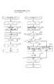
図7を用いて、監視装置1が被管理デバイスの部品カウンタを取得してからセンタ側管理サーバへデータを通知する処理のフローを説明する。まず、図9、図10、図11の説明を行う。
【0053】
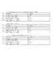
図9の(A)は部品交換履歴機能をサポートするデバイスから取得される部品カウンタ情報である。図9の(B)は、図9の(A)のデータ取得後にパーツが交換されていない場合、再度データ取得したときの部品カウンタ情報である。図9の(C)は図9の(A)のデータ取得後にパーツが交換された場合、再度データ取得したときの部品カウンタ情報である。
【0054】
図10の(A)は、部品交換履歴機能をサポートしていないデバイスから取得される部品カウンタ情報である。図10の(B)は図10の(A)のデータ取得後にパーツが交換されていない場合、再度データ取得したときの部品カウンタ情報である。図10の(C)は図10の(A)のデータ取得後にパーツが交換された場合、再度データ取得したときの部品カウンタ情報である。図10の(D)はz図10の(A)の部品データ取得後の監視装置1が管理しているカウンタ情報である。図10の(E)は図10の(C)の部品データ取得後の監視装置1が管理しているカウンタ情報である。
【0055】
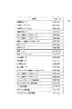
図11は、図8乃至図10におけるPARTS IDが適用される部品名の一例を示したものである。この図11に示されるような各部品における各単位(回数や枚数や時間)のカウンタ値が監視装置1やサーバ側管理装置2により取得される。尚、図11の1101が図9や図10におけるPARTS IDに対応する。
【0056】
次に図7の説明を行う。図7は、監視装置1がデバイスからパーツカウンタデータを取得し、前回交換時カウンタ値を補完してセンタ側管理サーバに通知するシーケンスを表わすフローチャートであり、画像形成装置における部品の使用履歴を取得可能な情報処理装置において、画像形成装置における部品のカウンタ値の取得し、取得したカウンタ値の大小関係を判定し、該判定によりカウンタ値が小さくなったと判定された場合には、交換前の部品を対象に最後に取得されたカウンタ値を交換前の部品の使用実績とする処理に対応する。この交換前の部品を対象に外部装置において取得されたカウンタ値を交換される部品の寿命実績とすることは、厳密でないにしても、おおよそ最終的に利用された使用実績に等しいものとなる。無論、部品カウンタを15分おきに行うなど、十分短い間隔で実行することを前提とする。
【0057】
S701でデバイスより部品カウンタを取得する。この取得は図1に示される複数の画像形成装置各々に対してなされ、また、各々の画像形成装置における各部品に対応して実行される。各部品毎に関して監視装置1で取得されるデータフォーマットは上に説明した図8の通りである。
【0058】
このとき取得されるデータの例を図9、10に示す。被管理デバイスが部品交換履歴機能を持っているのならば、図9(A)のように前回交換カウンタに適当な値が格納されている。反対に、被管理デバイスが部品交換履歴機能を持っていないならば、図10(A)のように前回交換カウンタには値0が格納されて返ってくることになる。
【0059】
したがって、S702において、取得した部品カウンタデータのなかの前回交換時カウンタに有効な値が入っていない(0が入っていた)場合は、そのデバイスは、前回交換時カウンタの履歴情報を保存する機能を有していないと判断し、本発明の監視装置1による補完処理を実施する。この補完処理はおおよその値を所定の部品の交換時の寿命として決定する処理に対応する。
【0060】
一方、前回交換時カウンタに有効な値が入っていれば、監視装置1による補完処理は必要ないので、取得した部品カウンタデータをS707でセンタ側管理サーバに通知する。尚、カウンタデータの取得対象となる画像形成装置が、S702における前回交換時カウンタの履歴情報を保存する機能を有しているか否かの切り分け判断は、上記仕組みに限定されるもんではなく、例えば監視装置1にデバイスモデル名と機能との対応関係テーブルを予め保持しておき、画像形成装置からデバイスモデル名を取得することにより判断するようにしても良い。
【0061】
本監視装置1では、図10(D)にあるように前回のカウンタ値および前回交換時カウンタが保存されている。前回カウンタ値はS705において保存が実行される。ここでの保持は、カウンタ取得デバイスから取得した使用状況のデータを記憶部に記憶させる処理に相当する。図7における他の保存処理も同様のものとする。
【0062】
S703において、本監視装置1で保存しておいた前回の部品カウンタ値と今回デバイスから取得した部品カウンタ値の比較を行う。前回のカウンタ値が図10の(A)のように取得されたとすると、監視装置1内では、図10(D)のようにそのカウンタ値が保存されている。
【0063】
部品の交換が行われていなければ、その使用量を示すカウンタは、図10の(B)のようになり、各カウンタは、前回と同じかそれ以上の値になっているはずである。
【0064】
反対に、今回の部品カウンタが図10の(C)のように、前回のカウンタ値よりも小さければ、それは、部品の交換によりカウンタがリセットされたことを意味する。カウンタのリセットは、部品の交換作業を行うサービスマンにより実行される。
【0065】
カウンタ値の逆転(大きなカウンタ値から小さいなカウンタ値へ変遷する)が起こっていた場合は、S704において前回交換時カウンタに、前回の部品カウンタを設定する。すなわち監視装置1では、図10の(E)の前回交換時カウンタが更新される。
【0066】
S705では、今回の取得カウンタ値を前回のカウンタ値として上書き保存する。
【0067】
すなわち、前回取得したカウンタ値が図10(A)であり、今回取得したカウンタ値が図10(C)であった場合、監視装置1内の保存データは、図10(D)から図10(E)になる。
【0068】
S706において、今回取得したカウンタ値(図10(B))に、監視装置1の保存するデータから前回交換時カウンタを上書きして、部品カウンタ情報を完成させる。
【0069】
S707では、各部品ごとに上記の手段でデータの補完作業を行ったデータから、センタ側管理サーバに通知するための所定のデータフォーマットに構成して、しかるべき通信手段を用いてセンタ側管理サーバに通知する。
【0070】
上に説明した、図7の処理により、前記取得手段によるカウンタ取得の対象(S701)となる画像形成装置が、交換前の部品の使用実績を外部に通知する機能を備えるか否かを切り分けること(S702)ができ、この切り分けと、前記取得手段により取得したカウンタ値ともに基づきS704やS705で交換前の部品の使用履歴を決定することができるようになった。これにより、交換前の部品における使用実績(各種カウンタ)をリセットしてしまい、外部装置に正確に通知することができないような画像形成装置と、交換前の部品における使用実績を外部装置に通知することができる機能を備えた画像形成装置とが混在するようなネットワーク印刷環境を対象に、画像形成装置の各部品の寿命基準を各画像形成装置の使用実績に沿ってより的確に管理することができるようになった。また、サービスマンなどが部品の交換の際に、画像形成装置に設けられた各部品毎の寿命カウンタをメモするなどの煩雑な作業をも軽減することができるようになった。
【0071】
また、部品交換履歴を保持する機能の有無にかかわらず被管理デバイスの部品カウンタの前回交換時カウンタをセンタ側管理サーバに通知することが可能となる。すなわち、センタ側管理サーバは、被管理デバイスの性能を考慮することなく、被管理デバイスを一律に管理することが可能となるため、センタ側管理サーバではデバイス種類により処理の追加等の負荷はなくなり、前回交換時カウンタ値が保証されることから、この前回交換時カウンタ値を有効に使用することが可能となる。
【0072】
[第2の実施の形態]
上記第1の実施の形態においては、監視装置1により、図7の補完処理を実行するように説明してきたが、本発明はこれに限定されるものではなく、図7のS702以降の処理の一部、或いは、全てをセンタ側管理サーバ6或いはPC7に実行させるようにしても良い。言い換えれば、画像形成装置における部品の使用履歴を取得可能な情報処理装置にS702以降の処理を実行させるような形態に本発明は適用可能となる。
【0073】
その場合には、図7のS701の処理は、各デバイスから取得した複数部品各々のカウンタデータをセンタ側管理サーバ6に通知する処理に置き換えることができる。尚、ここでは、第1の実施の形態との差異について特に説明するようにしたが、差異以外の構成は第2の実施の形態においても第1の実施の形態において説明した通りとするので、証左名説明は省略する。
【0074】
【発明の効果】
以上、説明してきたように、本発明によれば、画像形成装置における部品の使用履歴を取得可能な情報処理装置において、画像形成装置における部品のカウンタ値の取得し、取得したカウンタ値の大小関係を判定し、該判定によりカウンタ値が小さくなったと判定された場合には、交換前の部品を対象に最後に取得されたカウンタ値を交換前の部品の使用実績とする仕組みを実現することができるようになった。
【図面の簡単な説明】
【図1】本発明の実施の形態に係る情報処理装置が接続された、デバイス遠隔監視システムの全体構成例を示す概念図である。
【図2】図1における監視装置1のハードウェア構成を示すブロック図である。
【図3】監視装置1の処理を示すフローチャートである。
【図4】監視装置1の処理を示すフローチャートである。
【図5】図1におけるデバイス3〜5の一例である画像形成装置の全体の制御を司るコントローラの構成例を示すブロック図である。
【図6】画像形成装置のソフトウェア構成を示すブロック図である。
【図7】監視装置1が前回交換時カウンタのデータを管理する処理を示すフローチャートである。
【図8】監視装置1がセンタ側管理サーバに通知する部品カウンタのフォーマットである。
【図9】デバイスから取得される情報の様子を示す図である。
【図10】デバイスから取得される情報の様子を示す図である。
【図11】部品カウンタ情報をもつ部品とそのIDの一覧である。[0001]
TECHNICAL FIELD OF THE INVENTION
The present invention relates to a mechanism for managing the usage history of components of an image forming apparatus outside the image forming apparatus.
[0002]
[Prior art]
Consumable parts used in office equipment are expected to have a limited life, and a service person should use the service life as a guideline to determine whether the counter value for measuring the degree of wear has reached the expected life reference value. Exchange is taking place.
[0003]
Also, remotely obtain the value of the counter of the component of the image forming apparatus, determine whether the counter has reached the end of the life of the component, and replace the part that is about to reach the end of its service life with a serviceman. Was.
[0004]
[0005]
On the other hand, as a conventionally known technique, Japanese Patent Application Laid-Open Publication No. H11-163873 discloses an image for predicting a life reference corrected in accordance with the actual use in consideration of the life of a previously replaced part in a copying apparatus having replacement parts. Forming devices are known.
[0006]
As described above, regarding the components used in the image forming apparatus, the life of the components is remotely controlled as described in Japanese Patent Application Laid-Open No. H11-163873, and the method of using the components may differ from user to user as disclosed in Japanese Patent Application Laid-Open No. H10-287421. It is important to manage the performance of the used parts and use it as a guideline for the service life.
[0007]
[Patent Document 1]
JP-A-07-066685 [Patent Document 2]
Japanese Patent Application Laid-Open No. 01-123253
[Problems to be solved by the invention]
However, in managing the actual use history of a part by a remote external device, if the part is replaced, for example, a serviceman presses a counter reset button, or the counter of the part use status (for example, presses a counter reset button). The printed number counter is cleared, and the counter value in the image forming apparatus is increased or decreased, and there is a problem that the life history of the component cannot be accurately managed.
[0009]
On the other hand, a solution to provide a counter value (use history) of the usage status of the parts before replacement to a remote external device is also conceivable, but an image already used by a user is considered. Considering the maintenance management including the forming device, there is a problem that many devices do not have a function to notify the counter value of the usage status of the parts before replacement to a remote external device, and this does not provide a comprehensive solution. there were.
[0010]
SUMMARY OF THE INVENTION The present invention has been made in view of the above problems, and has an image forming apparatus that does not have a function of notifying a remote external device of a counter value of a use state of a component before replacement. An object is to provide a mechanism that can be managed by an external device that can communicate with a forming apparatus.
[0011]
[Means for Solving the Problems]
In order to solve the above problem, in an information processing apparatus capable of acquiring a use history of a component in an image forming apparatus, a counter value of a component in the image forming apparatus is acquired, and a magnitude relationship between the acquired counter values is determined. If it is determined by the determination that the counter value has decreased, a mechanism is provided in which the counter value obtained last for the parts before replacement is used in the parts before replacement.
[0012]
BEST MODE FOR CARRYING OUT THE INVENTION
Hereinafter, embodiments of the present invention will be described with reference to the drawings.
[0013]
[First Embodiment]
FIG. 1 is a diagram showing an entire configuration of a first embodiment of a remote monitoring system including a management device according to the present invention.
[0014]
In this remote monitoring system, the center-side management server 6 and the base-
[0015]
The center-side management server 6 and the base-
[0016]
The
[0017]
A personal computer (hereinafter, referred to as “PC”) 7 is connected to the center-side management server 6 via a network, and operates as a client computer of the center-side management server 6. The PC 7 can execute various types of information processing and share information collected by the center-side management server 6.
[0018]
In FIG. 1, the
[0019]
Although only one
[0020]
Specifically, the image forming apparatuses 3 to 5 in FIG. 1 include a printer (including an electrophotographic system and an ink jet system), a facsimile machine, a scanner, a printer, and a digital multifunction peripheral in which a facsimile function is integrally provided. One of a server and the like.
[0021]
1 converts, for example, predetermined application data into PDL (Page Description Language) data via an OS (Operating System) and a printer driver, and converts the PDL data into image forming apparatuses 3 to 5. It has a function to send to either.
[0022]
The
[0023]
FIG. 2 is a diagram showing a hardware block diagram of the
[0024]
A general configuration including an interface of a
[0025]
FIG. 3 is a flowchart showing a device failure monitoring process by the
[0026]
In step S302 of FIG. 3, the
[0027]
In step S304, the
[0028]
In step S308, after transmitting the failure information to the host in step S304, the
[0029]
In step S309, the
[0030]
In step S313, the
[0031]
FIG. 4 is a flowchart showing a counter information acquisition process in which the
[0032]
In FIG. 4, first, the
[0033]
When the counter information transmission program is executed, the
[0034]
In step S409, the
[0035]
As described above, the device failure information monitoring process described in FIG. 3 and the counter information acquisition process described in FIG. 4 are executed, so that the maintenance information in the image forming apparatus or the personal computer used at the user's site can be remotely transmitted. Centralized management is possible.
[0036]
<Block diagram of image forming apparatus>
Next, FIG. 5 is a block diagram illustrating a configuration of a controller that controls the entire image forming apparatus.
[0037]
As shown in FIG. 5, the controller has a CPU circuit unit (507). The
[0038]
A document feeder control unit (502) controls the drive of a document feeder (not shown) based on an instruction from 507. The image reader control unit (503) performs drive control on a scanner unit (not shown), an image sensor (not shown), and transfers an analog image signal output from the image sensor to the image signal control unit (504). I do.
[0039]
A
[0040]
An operation unit (511) includes a plurality of keys for setting various functions related to image formation, a display unit for displaying information indicating a setting state, and the like, and outputs a key signal corresponding to an operation of each key to 507. At the same time, corresponding information is displayed on the display unit (512) based on the signal from 507.
[0041]
The sorter control unit (513) and the finisher control unit (514) operate based on a signal from 507 according to an input from a user via 506 or a setting from 511. The state detection unit collects state information from each part, makes a determination such as abnormality detection, and notifies the result to 507. In accordance with this notification, 507 displays an abnormality on 501 or the like via 512 or 506.
[0042]
FIG. 6 shows a software configuration diagram of the image forming apparatus.
[0043]
The task manager (A-101) is for managing a plurality of tasks simultaneously. The paper transport unit task group (A-102) is a task group that manages paper transport of a document and a sheet on which an image is formed. The sequence control task (A-103) is a task for managing the entire image forming apparatus. The communication task (A-104) is a task for performing communication with the device management apparatus. There is also a management data creation task (A-105) for creating remote management data according to the present embodiment.
[0044]
The image forming apparatus counts for each sheet size, mode, sheet type, and color for each image formation. These counting results are performed in the management data creation task (A-105), and are stored in the memory device in the image forming apparatus.
[0045]
Similarly, status information such as a jam, an error, and an alarm is stored in a memory device in the image forming apparatus in a predetermined data format.
[0046]
Further, each unit in the image forming apparatus has a counter (hereinafter, referred to as a component counter) indicating the replacement life of constituent consumable parts and the number of times of use, and is included in the management data creation task (A-105). The counted result is stored in the memory device of the image forming apparatus.
[0047]
The image forming apparatus status monitoring task (A-106) detects an abnormality (jam, error, alarm) in the image forming apparatus or detects a change in the status of a preset device. The detection result is stored in the memory device of the image forming apparatus via the management data creation task A-105. Note that the detection mechanism in the present embodiment may be a mechanism using software using a timer, a flag, or the like, or a mechanism for acquiring output values of various sensors.
[0048]
The information stored in these memory devices is notified to the site-
[0049]
The above is the basic configuration of the present invention, and the complementing function of the component counter of the present invention will be described in detail with reference to FIGS.
[0050]
FIG. 8 shows a data format of a plurality of component counter information notified from the
[0051]
The data format is notified for each managed device. For each component (PARTS ID 805) held by the managed device, the PARTS counters 806 and 809 indicating the current usage of the component, the PARTS counters 807 and 810 at the time of the previous replacement, and the expected life (presumed by the manufacturer) A series of data consisting of (lifetime) 808 and 811, the date and time 812 when the last replacement was performed, and the total printed
[0052]
With reference to FIG. 7, a description will be given of a flow of a process in which the
[0053]
FIG. 9A shows component counter information acquired from a device that supports the component replacement history function. FIG. 9B shows component counter information when data is acquired again when parts are not replaced after the data acquisition in FIG. 9A. FIG. 9C shows component counter information when data is acquired again when parts are exchanged after the data acquisition in FIG. 9A.
[0054]
FIG. 10A shows component counter information acquired from a device that does not support the component replacement history function. FIG. 10B shows component counter information when data is acquired again when parts are not replaced after the data acquisition in FIG. 10A. FIG. 10C shows the component counter information when the data is acquired again when the parts are exchanged after the data acquisition in FIG. (D) of FIG. 10 is counter information managed by the
[0055]
FIG. 11 shows an example of a part name to which the PARTS ID in FIGS. 8 to 10 is applied. The counter value of each unit (number of times, number of sheets, time) of each component as shown in FIG. 11 is acquired by the
[0056]
Next, FIG. 7 will be described. FIG. 7 is a flowchart illustrating a sequence in which the
[0057]
In step S701, a component counter is obtained from the device. This acquisition is performed for each of the plurality of image forming apparatuses shown in FIG. 1, and is executed corresponding to each component in each image forming apparatus. The data format acquired by the
[0058]
Examples of data acquired at this time are shown in FIGS. If the managed device has the part replacement history function, an appropriate value is stored in the previous replacement counter as shown in FIG. Conversely, if the managed device does not have the component replacement history function, the
[0059]
Therefore, in S702, if the previous replacement counter in the acquired component counter data does not contain a valid value (the value is 0), the device saves the history information of the previous replacement counter. Is determined not to have, and the supplementary processing by the
[0060]
On the other hand, if the last replacement counter contains a valid value, no supplementary processing by the
[0061]
In the
[0062]
In S703, the previous component counter value stored in the
[0063]
If the parts have not been replaced, the counter indicating the used amount is as shown in FIG. 10B, and each counter should be equal to or larger than the previous time.
[0064]
Conversely, if the current component counter is smaller than the previous counter value as shown in FIG. 10C, it means that the counter has been reset by replacing the component. The resetting of the counter is executed by a service person who performs a part replacement operation.
[0065]
If the counter value has been reversed (transition from a large counter value to a small counter value) has occurred, the previous component counter is set as the previous replacement counter in S704. That is, in the
[0066]
In S705, the current obtained counter value is overwritten and stored as the previous counter value.
[0067]
That is, when the previously acquired counter value is as shown in FIG. 10A and the currently acquired counter value is as shown in FIG. 10C, the data stored in the
[0068]
In S706, the counter value at this time (FIG. 10B) is overwritten with the previous replacement counter from the data stored in the
[0069]
In S707, the data supplemented by the above-described means for each component is configured into a predetermined data format for notifying the center-side management server of the data, and the center-side management server is configured using appropriate communication means. Notify
[0070]
By the process of FIG. 7 described above, it is determined whether or not the image forming apparatus to be counter-acquired by the acquisition unit (S701) has a function of notifying the actual use of parts before replacement to the outside. (S702) can be performed, and the use history of the parts before replacement can be determined in S704 and S705 based on the separation and the counter value acquired by the acquisition unit. As a result, the use record (various counters) of the parts before replacement is reset, and the image forming apparatus that cannot accurately notify the external device and the record of use of the parts before replacement are notified to the external device. It is possible to more accurately manage the life standards of each part of the image forming apparatus according to the actual use of each image forming apparatus in a network printing environment where image forming apparatuses with functions capable of Now you can. Further, when a service person or the like replaces a part, complicated work such as writing down a life counter for each part provided in the image forming apparatus can be reduced.
[0071]
Further, it becomes possible to notify the center-side management server of the last replacement counter of the component counter of the managed device regardless of the presence or absence of the function of retaining the component replacement history. That is, since the center-side management server can uniformly manage the managed devices without considering the performance of the managed devices, the load on the center-side management server such as additional processing depending on the device type is eliminated. Since the previous replacement counter value is guaranteed, the previous replacement counter value can be used effectively.
[0072]
[Second embodiment]
In the first embodiment, the
[0073]
In this case, the process of S701 in FIG. 7 can be replaced with a process of notifying the center-side management server 6 of the counter data of each of the plurality of components acquired from each device. Here, the difference from the first embodiment is specifically described, but the configuration other than the difference is the same as that described in the first embodiment in the second embodiment. The description of the name is omitted.
[0074]
【The invention's effect】
As described above, according to the present invention, in an information processing apparatus capable of acquiring a use history of a component in an image forming apparatus, a counter value of a component in the image forming apparatus is acquired, and a magnitude relationship between the acquired counter values is obtained. And if it is determined that the counter value has become smaller, it is possible to realize a mechanism in which the last acquired counter value for the part before replacement is used as the actual use result of the part before replacement. Now you can.
[Brief description of the drawings]
FIG. 1 is a conceptual diagram showing an overall configuration example of a device remote monitoring system to which an information processing apparatus according to an embodiment of the present invention is connected.
FIG. 2 is a block diagram showing a hardware configuration of the
FIG. 3 is a flowchart showing a process of the
FIG. 4 is a flowchart showing a process of the
FIG. 5 is a block diagram illustrating a configuration example of a controller that controls the entire image forming apparatus as an example of the devices 3 to 5 in FIG.
FIG. 6 is a block diagram illustrating a software configuration of the image forming apparatus.
FIG. 7 is a flowchart showing a process in which the
FIG. 8 shows a format of a component counter notified by the
FIG. 9 is a diagram illustrating a state of information acquired from a device.
FIG. 10 is a diagram illustrating a state of information acquired from a device.
FIG. 11 is a list of components having component counter information and their IDs.
Claims (5)
Translated fromJapanese画像形成装置における部品のカウンタ値の取得をする取得手段と、
前記取得手段により取得したカウンタ値の大小関係を判定する判定手段を有し、前記判定手段によりカウンタ値が小さくなったと判定された場合には、交換前の部品を対象に最後に取得されたカウンタ値を交換前の部品の使用実績とすることを特徴とする情報処理装置。An information processing apparatus capable of acquiring a use history of parts in an image forming apparatus,
Acquiring means for acquiring a counter value of a component in the image forming apparatus;
A determining unit that determines a magnitude relationship between the counter values acquired by the acquiring unit; if the determining unit determines that the counter value has decreased, the counter acquired last for the part before replacement An information processing apparatus characterized in that a value is a use record of parts before replacement.
前記切分手段による切り分けと、前記取得手段により取得したカウンタ値ともに基づき交換前の部品の使用履歴を決定する決定手段、
前記決定手段により決定された前記交換前の部品の使用履歴を管理する管理手段とを有することを特徴とする請求項1に記載の情報処理装置。An image forming apparatus to be counter-acquired by the acquisition unit, and a separation unit for determining whether or not a function of notifying an external use result of parts before replacement is provided;
Determination means for determining the use history of the part before replacement based on both the separation by the separation means and the counter value acquired by the acquisition means,
2. The information processing apparatus according to claim 1, further comprising management means for managing a use history of the parts before replacement determined by the determination means.
画像形成装置における部品のカウンタ値の取得をする取得ステップと、
前記取得ステップにおいて取得されたカウンタ値の大小関係を判定する判定ステップを有し、前記判定ステップによりカウンタ値が小さくなったと判定された場合には、交換前の部品を対象に最後に取得されたカウンタ値を交換前の部品の使用実績とすることを特徴とする保守管理方法。A maintenance management method in an information processing apparatus capable of acquiring a use history of components in an image forming apparatus,
An obtaining step of obtaining a counter value of a component in the image forming apparatus;
A determining step of determining a magnitude relationship between the counter values obtained in the obtaining step; if the determining step determines that the counter value has decreased, the counter value is obtained last for the part before replacement A maintenance management method characterized in that a counter value is used as a result of using parts before replacement.
Priority Applications (2)
| Application Number | Priority Date | Filing Date | Title |
|---|---|---|---|
| JP2003132832AJP3840200B2 (en) | 2003-05-12 | 2003-05-12 | Information processing apparatus, maintenance management method, program, and storage medium |
| US10/837,679US7072799B2 (en) | 2003-05-12 | 2004-05-04 | Information processing apparatus, maintenance managing method, program, and computer-readable storing medium |
Applications Claiming Priority (1)
| Application Number | Priority Date | Filing Date | Title |
|---|---|---|---|
| JP2003132832AJP3840200B2 (en) | 2003-05-12 | 2003-05-12 | Information processing apparatus, maintenance management method, program, and storage medium |
Publications (3)
| Publication Number | Publication Date |
|---|---|
| JP2004334752Atrue JP2004334752A (en) | 2004-11-25 |
| JP2004334752A5 JP2004334752A5 (en) | 2005-12-22 |
| JP3840200B2 JP3840200B2 (en) | 2006-11-01 |
Family
ID=33410633
Family Applications (1)
| Application Number | Title | Priority Date | Filing Date |
|---|---|---|---|
| JP2003132832AExpired - Fee RelatedJP3840200B2 (en) | 2003-05-12 | 2003-05-12 | Information processing apparatus, maintenance management method, program, and storage medium |
Country Status (2)
| Country | Link |
|---|---|
| US (1) | US7072799B2 (en) |
| JP (1) | JP3840200B2 (en) |
Cited By (2)
| Publication number | Priority date | Publication date | Assignee | Title |
|---|---|---|---|---|
| JP2007141203A (en)* | 2005-10-21 | 2007-06-07 | Seiko Epson Corp | Network device monitoring |
| JP2011135356A (en)* | 2009-12-24 | 2011-07-07 | Konica Minolta Business Technologies Inc | Image forming apparatus and system |
Families Citing this family (2)
| Publication number | Priority date | Publication date | Assignee | Title |
|---|---|---|---|---|
| JP4497543B2 (en)* | 2004-12-15 | 2010-07-07 | コニカミノルタビジネステクノロジーズ株式会社 | Image forming system |
| JP4636933B2 (en)* | 2005-05-09 | 2011-02-23 | キヤノン株式会社 | Print control apparatus and print control method |
Family Cites Families (17)
| Publication number | Priority date | Publication date | Assignee | Title |
|---|---|---|---|---|
| WO1998029832A1 (en)* | 1996-12-25 | 1998-07-09 | Sony Corporation | Image processor, data processor, and their methods |
| US4377742A (en)* | 1979-05-23 | 1983-03-22 | Canon Kabushiki Kaisha | Image sharpness detecting system |
| US4870459A (en)* | 1987-11-06 | 1989-09-26 | Minolta Camera Kabushiki Kaisha | Copying machine |
| JP2806523B2 (en) | 1987-11-06 | 1998-09-30 | ミノルタ 株式会社 | Copier |
| DE69325946T2 (en)* | 1992-05-25 | 2000-04-20 | Canon K.K. | Mapping method and device |
| JP3296887B2 (en) | 1993-06-23 | 2002-07-02 | 株式会社リコー | Image forming device management system |
| JP3970430B2 (en)* | 1998-07-10 | 2007-09-05 | 株式会社リコー | Image forming apparatus service system |
| JP4038325B2 (en)* | 2000-06-26 | 2008-01-23 | シャープ株式会社 | Abnormal display device for image forming apparatus |
| JP4690532B2 (en)* | 2000-09-26 | 2011-06-01 | 株式会社日立製作所 | Image forming apparatus |
| JP4044301B2 (en)* | 2001-05-11 | 2008-02-06 | 株式会社リコー | Data communication apparatus, image forming apparatus management system using the same, and counter information transmission method thereof |
| JP3824927B2 (en)* | 2001-06-22 | 2006-09-20 | 株式会社リコー | Reading apparatus, image forming apparatus, communication apparatus, and abnormal pixel data acquisition method |
| JP2003108344A (en)* | 2001-09-28 | 2003-04-11 | Canon Inc | Diagnostic device, diagnostic system, diagnostic method, program, and medium |
| WO2003107235A1 (en)* | 2002-06-12 | 2003-12-24 | 日立建機株式会社 | Information providing system of construction machine and information providing method of construction machine |
| FR2842057B1 (en)* | 2002-07-05 | 2005-10-28 | Canon Kk | METHOD AND DEVICE FOR PROCESSING DATA IN A COMMUNICATION NETWORK |
| JP4065504B2 (en)* | 2002-07-17 | 2008-03-26 | キヤノン株式会社 | Image forming system, image distribution apparatus, and image forming method |
| DE10250820A1 (en)* | 2002-10-31 | 2004-05-13 | Francotyp-Postalia Ag & Co. Kg | Arrangement for printing a print image with areas of different print image resolution |
| JP2004170863A (en)* | 2002-11-22 | 2004-06-17 | Fuji Xerox Co Ltd | Image forming apparatus, method for managing replacement component for use in the same, and program for managing the replacement component |
- 2003
- 2003-05-12JPJP2003132832Apatent/JP3840200B2/ennot_activeExpired - Fee Related
- 2004
- 2004-05-04USUS10/837,679patent/US7072799B2/ennot_activeExpired - Fee Related
Cited By (2)
| Publication number | Priority date | Publication date | Assignee | Title |
|---|---|---|---|---|
| JP2007141203A (en)* | 2005-10-21 | 2007-06-07 | Seiko Epson Corp | Network device monitoring |
| JP2011135356A (en)* | 2009-12-24 | 2011-07-07 | Konica Minolta Business Technologies Inc | Image forming apparatus and system |
Also Published As
| Publication number | Publication date |
|---|---|
| JP3840200B2 (en) | 2006-11-01 |
| US20040228640A1 (en) | 2004-11-18 |
| US7072799B2 (en) | 2006-07-04 |
Similar Documents
| Publication | Publication Date | Title |
|---|---|---|
| USRE42166E1 (en) | Monitoring apparatus, management method and program therefor, and management apparatus and management method and program therefor | |
| JP4659667B2 (en) | Information processing apparatus and information processing method | |
| JP5539005B2 (en) | Information processing apparatus and method | |
| US8953193B2 (en) | Management system, monitoring apparatus and management | |
| JP2004221799A (en) | Device monitoring device | |
| JP2002082792A (en) | Management system, relay server, management device, management method, and image forming device | |
| JP2008147941A (en) | Monitoring device, image forming apparatus, monitoring system, network setting changing method, and program | |
| US7882180B2 (en) | Monitoring apparatus for image forming apparatus, control method executed by the monitoring apparatus, program for implementing the control method, and management apparatus, control method executed by the management apparatus, and program for implementing the control method | |
| JP7073820B2 (en) | Mediation device, equipment monitoring system, mediation method | |
| JP3840200B2 (en) | Information processing apparatus, maintenance management method, program, and storage medium | |
| JP2004362414A (en) | Information collection device, reboot method, program, and remote maintenance system | |
| JP2005165467A (en) | Information processing apparatus and method, and program | |
| US7249706B2 (en) | Information collector, resetting method, program and remote maintenance system | |
| JP4187668B2 (en) | Image forming apparatus and automatic reboot method | |
| JP2005134984A (en) | Information processing apparatus, failure notification method, and program | |
| JP2004334079A (en) | Information collection device and information collection method | |
| JP4142361B2 (en) | Device management system, management device, and managed device | |
| JP7242303B2 (en) | Network device, method and program | |
| JP2019093578A (en) | Image formation apparatus, control method and program | |
| JP2005258164A (en) | Remote maintenance system, information processing apparatus, information processing method, and program | |
| JP2004086033A (en) | Remote management device | |
| JP2008294739A (en) | Remote device monitoring apparatus, remote device monitoring method, and program for executing remote monitoring device monitoring method | |
| JP2005135333A (en) | Program monitoring device, program monitoring method, program, storage medium, and information acquisition system | |
| JP4589767B2 (en) | Managed apparatus, control method of managed apparatus, program, and recording medium | |
| JP2022175702A (en) | Information processing device, method and program |
Legal Events
| Date | Code | Title | Description |
|---|---|---|---|
| A521 | Request for written amendment filed | Free format text:JAPANESE INTERMEDIATE CODE: A523 Effective date:20051031 | |
| A977 | Report on retrieval | Free format text:JAPANESE INTERMEDIATE CODE: A971007 Effective date:20060419 | |
| A131 | Notification of reasons for refusal | Free format text:JAPANESE INTERMEDIATE CODE: A131 Effective date:20060425 | |
| A521 | Request for written amendment filed | Free format text:JAPANESE INTERMEDIATE CODE: A523 Effective date:20060626 | |
| TRDD | Decision of grant or rejection written | ||
| A01 | Written decision to grant a patent or to grant a registration (utility model) | Free format text:JAPANESE INTERMEDIATE CODE: A01 Effective date:20060801 | |
| A61 | First payment of annual fees (during grant procedure) | Free format text:JAPANESE INTERMEDIATE CODE: A61 Effective date:20060804 | |
| R150 | Certificate of patent or registration of utility model | Free format text:JAPANESE INTERMEDIATE CODE: R150 | |
| FPAY | Renewal fee payment (event date is renewal date of database) | Free format text:PAYMENT UNTIL: 20090811 Year of fee payment:3 | |
| FPAY | Renewal fee payment (event date is renewal date of database) | Free format text:PAYMENT UNTIL: 20100811 Year of fee payment:4 | |
| FPAY | Renewal fee payment (event date is renewal date of database) | Free format text:PAYMENT UNTIL: 20110811 Year of fee payment:5 | |
| FPAY | Renewal fee payment (event date is renewal date of database) | Free format text:PAYMENT UNTIL: 20120811 Year of fee payment:6 | |
| FPAY | Renewal fee payment (event date is renewal date of database) | Free format text:PAYMENT UNTIL: 20120811 Year of fee payment:6 | |
| FPAY | Renewal fee payment (event date is renewal date of database) | Free format text:PAYMENT UNTIL: 20130811 Year of fee payment:7 | |
| LAPS | Cancellation because of no payment of annual fees |