JP2004329883A - Bone fixation piece - Google Patents
Bone fixation pieceDownload PDFInfo
- Publication number
- JP2004329883A JP2004329883AJP2004078596AJP2004078596AJP2004329883AJP 2004329883 AJP2004329883 AJP 2004329883AJP 2004078596 AJP2004078596 AJP 2004078596AJP 2004078596 AJP2004078596 AJP 2004078596AJP 2004329883 AJP2004329883 AJP 2004329883A
- Authority
- JP
- Japan
- Prior art keywords
- bone
- shaft
- fixation element
- bone fixation
- anchoring element
- Prior art date
- Legal status (The legal status is an assumption and is not a legal conclusion. Google has not performed a legal analysis and makes no representation as to the accuracy of the status listed.)
- Granted
Links
- 210000000988bone and boneAnatomy0.000titleclaimsabstractdescription163
- 238000004873anchoringMethods0.000claimsdescription55
- 238000000034methodMethods0.000claimsdescription5
- 229910001285shape-memory alloyInorganic materials0.000claimsdescription3
- 238000013461designMethods0.000description4
- 238000003780insertionMethods0.000description4
- 230000037431insertionEffects0.000description4
- 238000001356surgical procedureMethods0.000description4
- 230000006870functionEffects0.000description3
- 230000036760body temperatureEffects0.000description2
- 238000011161developmentMethods0.000description2
- 230000018109developmental processEffects0.000description2
- 238000005553drillingMethods0.000description2
- 239000000463materialSubstances0.000description2
- 229910000831SteelInorganic materials0.000description1
- RTAQQCXQSZGOHL-UHFFFAOYSA-NTitaniumChemical compound[Ti]RTAQQCXQSZGOHL-UHFFFAOYSA-N0.000description1
- 239000002639bone cementSubstances0.000description1
- 230000001419dependent effectEffects0.000description1
- 239000003814drugSubstances0.000description1
- 229940079593drugDrugs0.000description1
- -1for exampleInorganic materials0.000description1
- 229910052588hydroxylapatiteInorganic materials0.000description1
- 238000001802infusionMethods0.000description1
- 238000012986modificationMethods0.000description1
- 230000004048modificationEffects0.000description1
- 229910001000nickel titaniumInorganic materials0.000description1
- HLXZNVUGXRDIFK-UHFFFAOYSA-Nnickel titaniumChemical compound[Ti].[Ti].[Ti].[Ti].[Ti].[Ti].[Ti].[Ti].[Ti].[Ti].[Ti].[Ni].[Ni].[Ni].[Ni].[Ni].[Ni].[Ni].[Ni].[Ni].[Ni].[Ni].[Ni].[Ni].[Ni]HLXZNVUGXRDIFK-UHFFFAOYSA-N0.000description1
- XYJRXVWERLGGKC-UHFFFAOYSA-Dpentacalcium;hydroxide;triphosphateChemical compound[OH-].[Ca+2].[Ca+2].[Ca+2].[Ca+2].[Ca+2].[O-]P([O-])([O-])=O.[O-]P([O-])([O-])=O.[O-]P([O-])([O-])=OXYJRXVWERLGGKC-UHFFFAOYSA-D0.000description1
- 230000000717retained effectEffects0.000description1
- 238000007493shaping processMethods0.000description1
- 239000010959steelSubstances0.000description1
- 229910052719titaniumInorganic materials0.000description1
- 239000010936titaniumSubstances0.000description1
Images


Classifications
- A—HUMAN NECESSITIES
- A61—MEDICAL OR VETERINARY SCIENCE; HYGIENE
- A61B—DIAGNOSIS; SURGERY; IDENTIFICATION
- A61B17/00—Surgical instruments, devices or methods
- A61B17/56—Surgical instruments or methods for treatment of bones or joints; Devices specially adapted therefor
- A61B17/58—Surgical instruments or methods for treatment of bones or joints; Devices specially adapted therefor for osteosynthesis, e.g. bone plates, screws or setting implements
- A61B17/68—Internal fixation devices, including fasteners and spinal fixators, even if a part thereof projects from the skin
- A61B17/84—Fasteners therefor or fasteners being internal fixation devices
- A61B17/86—Pins or screws or threaded wires; nuts therefor
- A61B17/8625—Shanks, i.e. parts contacting bone tissue
- A—HUMAN NECESSITIES
- A61—MEDICAL OR VETERINARY SCIENCE; HYGIENE
- A61B—DIAGNOSIS; SURGERY; IDENTIFICATION
- A61B17/00—Surgical instruments, devices or methods
- A61B17/56—Surgical instruments or methods for treatment of bones or joints; Devices specially adapted therefor
- A61B17/58—Surgical instruments or methods for treatment of bones or joints; Devices specially adapted therefor for osteosynthesis, e.g. bone plates, screws or setting implements
- A61B17/68—Internal fixation devices, including fasteners and spinal fixators, even if a part thereof projects from the skin
- A61B17/70—Spinal positioners or stabilisers, e.g. stabilisers comprising fluid filler in an implant
- A61B17/7001—Screws or hooks combined with longitudinal elements which do not contact vertebrae
- A61B17/7032—Screws or hooks with U-shaped head or back through which longitudinal rods pass
- A—HUMAN NECESSITIES
- A61—MEDICAL OR VETERINARY SCIENCE; HYGIENE
- A61B—DIAGNOSIS; SURGERY; IDENTIFICATION
- A61B17/00—Surgical instruments, devices or methods
- A61B17/56—Surgical instruments or methods for treatment of bones or joints; Devices specially adapted therefor
- A61B17/58—Surgical instruments or methods for treatment of bones or joints; Devices specially adapted therefor for osteosynthesis, e.g. bone plates, screws or setting implements
- A61B17/68—Internal fixation devices, including fasteners and spinal fixators, even if a part thereof projects from the skin
- A61B17/70—Spinal positioners or stabilisers, e.g. stabilisers comprising fluid filler in an implant
- A61B17/7001—Screws or hooks combined with longitudinal elements which do not contact vertebrae
- A61B17/7035—Screws or hooks, wherein a rod-clamping part and a bone-anchoring part can pivot relative to each other
- A61B17/7037—Screws or hooks, wherein a rod-clamping part and a bone-anchoring part can pivot relative to each other wherein pivoting is blocked when the rod is clamped
- A—HUMAN NECESSITIES
- A61—MEDICAL OR VETERINARY SCIENCE; HYGIENE
- A61B—DIAGNOSIS; SURGERY; IDENTIFICATION
- A61B17/00—Surgical instruments, devices or methods
- A61B17/56—Surgical instruments or methods for treatment of bones or joints; Devices specially adapted therefor
- A61B17/58—Surgical instruments or methods for treatment of bones or joints; Devices specially adapted therefor for osteosynthesis, e.g. bone plates, screws or setting implements
- A61B17/68—Internal fixation devices, including fasteners and spinal fixators, even if a part thereof projects from the skin
- A61B17/72—Intramedullary devices, e.g. pins or nails
- A61B17/7233—Intramedullary devices, e.g. pins or nails with special means of locking the nail to the bone
- A—HUMAN NECESSITIES
- A61—MEDICAL OR VETERINARY SCIENCE; HYGIENE
- A61B—DIAGNOSIS; SURGERY; IDENTIFICATION
- A61B17/00—Surgical instruments, devices or methods
- A61B2017/00831—Material properties
- A61B2017/00858—Material properties high friction or non-slip
- A—HUMAN NECESSITIES
- A61—MEDICAL OR VETERINARY SCIENCE; HYGIENE
- A61B—DIAGNOSIS; SURGERY; IDENTIFICATION
- A61B17/00—Surgical instruments, devices or methods
- A61B2017/00831—Material properties
- A61B2017/00867—Material properties shape memory effect
- A—HUMAN NECESSITIES
- A61—MEDICAL OR VETERINARY SCIENCE; HYGIENE
- A61F—FILTERS IMPLANTABLE INTO BLOOD VESSELS; PROSTHESES; DEVICES PROVIDING PATENCY TO, OR PREVENTING COLLAPSING OF, TUBULAR STRUCTURES OF THE BODY, e.g. STENTS; ORTHOPAEDIC, NURSING OR CONTRACEPTIVE DEVICES; FOMENTATION; TREATMENT OR PROTECTION OF EYES OR EARS; BANDAGES, DRESSINGS OR ABSORBENT PADS; FIRST-AID KITS
- A61F2/00—Filters implantable into blood vessels; Prostheses, i.e. artificial substitutes or replacements for parts of the body; Appliances for connecting them with the body; Devices providing patency to, or preventing collapsing of, tubular structures of the body, e.g. stents
- A61F2/0077—Special surfaces of prostheses, e.g. for improving ingrowth
Landscapes
- Health & Medical Sciences (AREA)
- Orthopedic Medicine & Surgery (AREA)
- Life Sciences & Earth Sciences (AREA)
- Surgery (AREA)
- Neurology (AREA)
- Heart & Thoracic Surgery (AREA)
- Engineering & Computer Science (AREA)
- Biomedical Technology (AREA)
- Nuclear Medicine, Radiotherapy & Molecular Imaging (AREA)
- Medical Informatics (AREA)
- Molecular Biology (AREA)
- Animal Behavior & Ethology (AREA)
- General Health & Medical Sciences (AREA)
- Public Health (AREA)
- Veterinary Medicine (AREA)
- Surgical Instruments (AREA)
Abstract
Description
Translated fromJapaneseこの発明は機械的な装置を骨に固定するための骨固定要素に関する。 The invention relates to a bone anchoring element for anchoring a mechanical device to bone.
茎状のねじの形のこの種の骨固定要素はDE42 34 118に記載されている。それはシャフト、およびロッドに接続可能な頭部を含む。シャフトにはねじが設けられ、これによってねじを骨に捩じ込むことができる。 Such a bone anchoring element in the form of a pedicle screw is described in
DE43 07 576は、骨ねじの頭部とロッドとの間に多軸接続を備えた骨固定要素について記載している。 DE 43 07 576 describes a bone fixation element with a polyaxial connection between the head of a bone screw and a rod.
上述の種類の骨固定要素は捩じ込むことで骨に挿入されるが、これは比較的時間がかかり力を要するプロセスである。さらに、古典的な捩じ込みのプロセスは骨に大きな圧力が作用することがあり、古い骨または既に損傷している骨の場合には望ましくない。 Bone fixation elements of the type described above are inserted into the bone by screwing in, which is a relatively time-consuming and forceful process. Furthermore, the classical screwing process can exert great pressure on the bone, which is undesirable in the case of old or already damaged bone.
このため、古典的な捩じ込みのプロセスは、特に小児外科、脊椎外科および神経外科などでの臨床的要件に好適ではない。
したがって、この発明は、すばやくかつ容易に少ない力で挿入することができ、骨を損傷する力を作用することなく確実な装着を実現する、特に小児外科、脊椎外科および神経外科で使用するための骨固定要素を提供するという課題に基づく。 Thus, the present invention can be inserted quickly and easily with low force and provides a secure fit without exerting bone damaging forces, especially for use in pediatric surgery, spine surgery and neurosurgery Based on the task of providing a bone anchoring element.
この課題は請求項1に記載の骨固定要素によって解決される。この発明のさらに別の展開例は従属項に記載される。 This task is solved by a bone anchoring element according to
骨ねじを形成しない領域を設けることによって、骨に以前に生成された装着孔へと骨固定要素を押込むかまたは挿入し、捩じ込みのプロセスを伴うことなくそれを予め定められた角度だけ回転させることで固定することが可能である。 By providing an area that does not form a bone screw, the bone fixation element is pushed or inserted into a previously created mounting hole in the bone, and it is moved by a predetermined angle without the screwing process. It is possible to fix by rotating.
この発明のさらに別の特徴および機能は添付の図面に基づく実施例の説明から明らかである。 Further features and functions of the present invention will be apparent from the description of the embodiments with reference to the accompanying drawings.
この発明の第1の実施例による骨固定要素を図1から図5を参照して説明する。 A bone anchoring element according to a first embodiment of the present invention will be described with reference to FIGS.
図1に最もよく示されるように、骨固定要素1は頭部2およびシャフト3を含む。頭部2は球体のセグメント状になるように設けられ、回転ツールが係合することのできる、たとえば、スロット、クロススロット、六角形の窪みまたは外側の六角形もしくは類似の装置などの装置(図示せず)を含む。 As best shown in FIG. 1, the
シャフト3は頭部と反対の端部に先端4を含む。骨ねじ5はシャフトの全長にわたって延在する。 The
シャフト3の2つの対向する側には2つの水平面6、7が設けられ、これらは互いにおよびシャフトの軸(シャフト3の長手軸)に対して平行でかつシャフトの全長にわたって延在する。面6、7の間の距離は骨ねじ5の谷径よりも小さいため、面6、7は骨ねじ5を中断する。 On the two opposing sides of the
図2に最もよく示されるように、シャフト3の断面はほぼ長方形になり、ねじによって形成される凹型の細い側を有する。断面の第1の大きさは面6、7の間の距離によって決まり、第1の方向に直交する第2の大きさは骨ねじ5の外側の大きさによって決まる。 As best shown in FIG. 2, the cross section of the
骨固定要素1はスチール、チタンまたは人体に適合性がありかつ十分に安定した材料で作られる。 The
固定要素1を挿入するため、図5に最もよく示されるように、まず対応する長円形の孔8が骨に生成される。これは、たとえばドリルで対をなす孔を開け、続いてヤスリを用いて分離壁を取除くことによって実現できる。またはこれに代えて、長円形の孔は横送りカッターまたは輪郭形成カッターを用いて生成してもよい。長円形の孔8の輪郭はシャフト3の断面にほぼ対応する。しかしながら、わずかに小さくてもよい。 To insert the
続いて、骨固定要素1のシャフト3は、シャフト3の断面の長手軸が長円形の孔8の長手軸とほぼ同一となるように押込むかまたは打込むことによって長円形の孔8に挿入される。この配置では、骨固定要素1はまだ引っ張ることによって取外すことができるような強さで長円形の孔8に取付けられている。 Subsequently, the
続いて、骨固定要素1は、図5の破線によって示されるように、頭部に係合する回転ツールによってある予め定められた角度、好ましくは90°回転される。結果として、骨ねじ5の歯は骨と係合し、骨固定要素はしっかりと取付けられる。 Subsequently, the
それをさらに180°の角度まで回転させるかまたは回転させて最初の位置まで戻すことで、骨固定要素1は緩めることができ、必要であれば骨から引抜くことができる。 By rotating it to a further 180 ° or rotating it back to its initial position, the
時間が経つにつれ、骨が空間へと成長し、骨固定要素1の安定性が増す。 Over time, bone grows into space and the stability of the bone anchoring
場合によっては、長い時間が経ち、骨固定要素1が骨によってしっかりと囲まれたときに、たとえば固定された装置を取外すときなど、骨固定要素1を骨から取外す必要がある場合がある。このとき、要素を単に回転させて戻して引抜くことはもはや不可能である。この場合、骨ねじ5は、従来の骨ねじと同様に回転ツールを用いてねじを緩めることで骨から骨固定要素1を取外すのを可能にする。 In some cases, after a long period of time, it may be necessary to remove the
図6は、この発明による第2の実施例を示す。水平面6、7の代わりに、骨固定要素1のシャフト3は2つの対向する面11、12を有し、これらはシャフト3の断面が凹型の長手方向の側を有するようにシャフトの軸の方向に湾曲している。その他の点では、骨固定要素1の設計および使用は第1の実施例と同一である。 FIG. 6 shows a second embodiment according to the present invention. Instead of
凹型になるように面11、12を設けることで、骨の材料の内生が向上し、骨固定要素1の骨での装着の安定性が増す。 Providing the
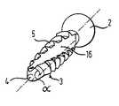
図7は、この発明による第3の実施例を示す。面6、7または11、12の代わりに、骨固定要素1のシャフト3は2つの対向する面16、17を含み、これらは螺旋部分を形成するようにある予め定められた角度αだけシャフトの軸のまわりで捩じれる。その他の
点では、骨固定要素1の設計および使用は第1の実施例と同一である。FIG. 7 shows a third embodiment according to the present invention. Instead of the
図7では、予め定められた角度αは例示のため約90°で示されているが、この角度は90°±45°の範囲にあることが好ましい。面16、17がわずかに捩じれることで、骨固定要素1の骨での固定が向上する。 In FIG. 7, the predetermined angle α is shown as approximately 90 ° for illustration, but it is preferable that this angle be in the range of 90 ° ± 45 °. The slight twisting of the
第2の実施例の面11、12と同様に、第3の実施例の面16、17は凹型になるように設けてもよい。 Similarly to the
この発明による第4の実施例による骨固定要素を図8から図10を参照して説明する。2つの平行な面6、7の代わりに、骨固定要素1のシャフト3は3つの面21、22、23を含み、これらは各々互いから120°オフセットされ、シャフト3の断面はほぼ三角形になる。骨ねじを形成しない面21、22、23とシャフトの軸との間の距離は骨ねじ5の中心半径より小さいため、面21、22、23は骨ねじ5を中断する。その他の点では、骨固定要素1の設計および使用は第1の実施例と同一である。 A bone anchoring element according to a fourth embodiment of the present invention will be described with reference to FIGS. Instead of two
第4の実施例によると、図10に最もよく示されるように、骨固定要素1を挿入するために、まず対応する三角形の孔28が骨に生成される。これは、たとえばドリルで孔を開け、続いてヤスリを用いて形作ることで実現できる。またはこれに代えて、三角形の孔28は横送りカッターまたは輪郭形成カッターを用いて生成してもよい。三角形の孔28の断面は、シャフト3の断面にほぼ対応するかまたはそれよりわずかに小さい。 According to a fourth embodiment, a corresponding
続いて、骨固定要素1のシャフト3は押込むかまたは打込むことによって三角形の孔28に挿入され、シャフト3の断面の三角形の側は三角形の孔28の三角形の側にほぼ対応する。この配置では、骨固定要素1は、まだ引っ張ることで取外すことができるような強さで三角形の孔28に取付けられている。 Subsequently, the
次に、骨固定要素1は、頭部に係合する回転ツールによってある予め定められた角度、好ましくは60°(図10の破線で示される)回転される。結果として、骨ねじ5の歯は骨に係合し、骨固定要素1はしっかりと取付けられる。 Next, the
さらに120°の角度まで回転させるかまたは回転させて最初の位置まで戻すことで、骨固定要素1は緩めることができ、必要であれば骨から引抜くことができる。 By turning or turning back to a further angle of 120 °, the
上述のように、第4の実施例の骨固定要素1は、長い時間が経って骨によってしっかりと囲まれたときに、従来の骨ねじと同様に回転ツールを用いてそれを緩めることで骨から取外すことができる。 As mentioned above, the
第2の実施例の面11、12と同様に、第4の実施例の面21、22、23は凹型の形状になるように設けてもよいし、および/または第3の実施例の面16、17のように互いに対して捩じれるように設けてもよい。 As with the
最初の4つの実施例で説明した骨固定要素は、椎弓根に挿入するのに理想的であるが、機械的な装置が固定される他のすべての骨にも理想的である。骨固定要素とロッドとの間の2種類の接続を骨固定要素と外部の装置との接続の例として以下に説明する。 The bone fixation elements described in the first four embodiments are ideal for insertion into a pedicle, but also ideal for all other bones to which mechanical devices are fixed. Two types of connections between the bone fixation element and the rod are described below as examples of the connection between the bone fixation element and an external device.
図11は骨固定要素1とロッド30との間の単軸接続の概略図である。 FIG. 11 is a schematic view of a uniaxial connection between the
骨固定要素1の頭部2はロッド30のための受部31として設けられ、U字型の窪み32を含み、これによって2つの自由脚33、34が形成される。U字型の窪み32の幅は
ロッド30の直径にほぼ対応する。内面ねじ35は自由脚33、34の内側に設けられる。The
骨固定要素1を骨に挿入した後、ロッド30がU字型の窪み32へと挿入される。続いて、ねじ36は、ねじ36とU字型の窪み32のベースとの間でロッド30が固定されるように十分に内面ねじ35へと捩じ込まれる。 After inserting the
シャフト3と受部との間の他の種類の単軸接続も可能である。さらに、ロッドのための受部の設計は図示の実施例に限定されない。たとえば、1つの修正例では、受部は内面ねじを含まない。この例では、受部はねじ切りロッドに接続され、側に係合するナットによって固定される。 Other types of single-axis connections between the
図12は骨固定要素1とロッド40との間の多軸接続の概略図である。 FIG. 12 is a schematic view of a polyaxial connection between the
接続を実現するため、本質的に筒状の受部41が長手方向のボア42とともに設けられる。長手方向のボア42の直径は骨固定要素1の球体のセグメント状の頭部2の直径よりわずかに大きい。長手方向のボア42は受部41の第1の端部から第1の端部と反対の第2の端部まで延在する。球体のセグメント状の窪み43は、直径が骨固定要素1の球体のセグメント状の頭部2の直径とほぼ同一であり、受部41の第2の端部と長手方向のボア42との間に設けられる。 To achieve the connection, an essentially cylindrical receiving part 41 is provided with a
さらに、受部41はU字型の窪み(図示せず)を含み、その幅はロッド40の直径にほぼ対応する。このU字型の窪みは受部41に2つの脚44、45を形成する。脚44、45の内側には内面ねじ46が設けられ、外側には外面ねじ47が設けられる。 Furthermore, the receiving part 41 includes a U-shaped recess (not shown), the width of which substantially corresponds to the diameter of the
さらに、スリーブ状の圧力要素50が設けられる。スリーブ状の圧力要素50の一端には、骨固定要素1の球体のセグメント状の頭部2とほぼ同じ直径を有する球体のセグメント状の窪み51が設けられ、他端には、ロッド40とほぼ同じ直径を有する筒セグメント状の窪み52が設けられる。 Furthermore, a sleeve-shaped
さらに、ロッドおよび頭部を固定するため、内面ねじ46に捩じ込むことができる内面ねじ56、および外面ねじ47に捩じ込むことのできるナット57が設けられる。 Further, an
動作において、骨固定要素1のシャフト3は受部41に挿入され、骨固定要素1の頭部2が球体のセグメント状の部分43内に保持されるまで受部41の第1の端部から進む。続いて、骨固定要素1は骨に導入される。このため、骨固定要素1は上述のように以前に骨に生成された孔へと押込まれるかまたは打込まれる。 In operation, the
続いて、受部41の第1の端部から進んで、スリーブ状の圧力要素50が長手方向のボア42へとスライドされ、球体のセグメント状の窪み51は骨固定要素1の頭部2上にくる。次いでロッド30がU字型の窪みに挿入され、圧力要素50の筒セグメント状の窪み52内にくる。 Subsequently, proceeding from the first end of the receiving part 41, the sleeve-shaped
続いて、ねじ56が内面ねじ46へと捩じ込まれ、骨固定要素1の頭部2は圧力要素50によって固定される。同時にロッド40はねじ56によって固定される。最後に、ナット57が外面ねじ47へと捩じ込まれて固定を確実にする。 Subsequently, the
上述の頭部と受部との間の多軸接続は単なる例として示される。他の種類の多軸接続も可能である。 The multi-axial connection between the head and receiver described above is shown by way of example only. Other types of multi-axis connections are possible.
第1から第4の実施例に示される球体のセグメント状の頭部は、上述の骨固定要素と外部の装置との間の多軸接続に特に好適である。しかしながら、骨固定要素には、外部の装置を多軸または単軸の態様で接続および/または固定して接続することを可能にするものであればどのような形状の頭部を設けてもよい。これは、プレートを骨に固定するための単なる皿穴または丸平の頭部を設けることを含む。 The segmented heads of the spheres shown in the first to fourth embodiments are particularly suitable for a polyaxial connection between the bone anchoring element described above and an external device. However, the bone anchoring element may be provided with a head of any shape that allows external devices to be connected and / or fixedly connected in a multiaxial or uniaxial manner. . This involves providing a simple countersink or round head for securing the plate to the bone.
またはこれに代えて、骨固定要素のシャフトは先端を有さないように設けてもよい。さらに、骨への挿入を容易にするためにわずかに円錐形の形状になるように設けてもよい。 Alternatively, the shaft of the bone anchoring element may be provided without a tip. Further, it may be provided with a slightly conical shape to facilitate insertion into bone.
ねじはシャフトの全長にわたって延在するのではなく、シャフトの予め定められた部分のみに延在してもよい。 The screw may not extend over the entire length of the shaft, but only over a predetermined portion of the shaft.
骨ねじを形成しない面の数は2つまたは3つに限定されない。これに代えて、1つのみまたは3つより多い数の面を設けてもよい。 The number of surfaces that do not form bone screws is not limited to two or three. Alternatively, only one or more than three surfaces may be provided.
シャフトの軸からの面の距離は必ずしも骨ねじ5の中心半径より小さい必要はない。中心半径と同一かまたはそれより大きくなるように選択してもよい。しかし、どの場合でも、骨ねじの先端とシャフトの軸との間の距離よりも小さくなくてはならない。 The distance of the surface from the axis of the shaft need not necessarily be smaller than the central radius of the
凹型の面11、12に対応する面は幅全体にわたって湾曲する必要はない。面の一部のみが湾曲する場合でも十分である。 The surfaces corresponding to the
骨の内生を向上するため、面を粗くするか、および/または、たとえばハイドロキシアパタイトを用いてコーティングしてもよい。 The surface may be roughened and / or coated with, for example, hydroxyapatite to improve bone endogenesis.
さらに、骨固定要素には、その頭部を通って延在しかつ先端で開口するかまたは閉鎖する長手方向のボア、およびその長手方向のボアから横方向に分岐しかつシャフトの横方向の壁で開口するボアを設けてもよく、前記ボアは薬物または骨用セメントを装着ボアへと注入するのを可能にする。 In addition, the bone fixation element has a longitudinal bore extending through its head and opening or closing at the tip, and a lateral wall diverging laterally from the longitudinal bore and a lateral wall of the shaft. A bore may be provided that opens at the bore, said bore allowing for infusion of drug or bone cement into the mounting bore.
さらに別の展開例では、骨固定要素は、たとえばニチノールなどの形状記憶合金から作られて設けられる。この場合、骨固定要素は、たとえば、室温では骨ねじを形成しない面が水平でかつ互いに平行である図1に対応する形状を取り、体温では面が互いに対して捩じれる図7に対応する形状を取るように設けてもよい。室温での挿入中、平行な面は骨固定要素を容易に挿入できるようにする。一旦体内に入ると、骨固定要素の形状は変化し、面が捩じれて骨の中での安定性が増す。 In yet another development, the bone anchoring element is provided made of a shape memory alloy such as, for example, Nitinol. In this case, the bone anchoring element takes the shape corresponding to FIG. 1, for example, at room temperature, where the surfaces that do not form bone screws are horizontal and parallel to each other, and at body temperature, the shape corresponding to FIG. May be provided. During insertion at room temperature, the parallel surfaces allow easy insertion of the bone anchoring element. Once in the body, the shape of the bone anchoring element changes and the surface twists to increase stability within the bone.
形状記憶合金から作られる骨固定要素は、骨ねじの歯が体温の場合より室温の場合に小さくなるように設けてもよい。結果として、骨ねじの歯は一旦体内に入ると大きくなり、骨の中での安定性が増す。 Bone fixation elements made from a shape memory alloy may be provided such that the teeth of the bone screw are smaller at room temperature than at body temperature. As a result, once the bone screw teeth enter the body, they become more stable in the bone.
1 骨固定要素、2 頭部、3 シャフト、6、7;11、12;16、17;21、22、23 骨ねじを形成しない面。 1 Bone fixation element, 2 heads, 3 shafts, 6, 7; 11, 12; 16, 17; 21, 22, 23 Surfaces that do not form bone screws.
Claims (14)
Translated fromJapanese前記外部の装置に接続可能な頭部(2)と、
骨に固定可能でかつ予め定められた部分に骨ねじ(5)を含むシャフト(3)とを含み、
前記シャフト(3)は、本質的に前記シャフトの軸の方向に沿って前記予め定められた部分の第1の端部から第2の端部へと延在する少なくとも1つの骨ねじを形成しない面(6、7;11、12;16、17;21、22、23)を含むことを特徴とする、骨固定要素(1)。A bone fixation element (1) for fixing an external device to bone,
A head (2) connectable to the external device;
A shaft (3) fixable to bone and including a bone screw (5) in a predetermined portion;
The shaft (3) does not essentially form at least one bone screw extending from a first end to a second end of the predetermined portion along the direction of the axis of the shaft. Bone fixation element (1), characterized in that it comprises surfaces (6, 7; 11, 12; 16, 17; 21, 22, 23).
Applications Claiming Priority (1)
| Application Number | Priority Date | Filing Date | Title |
|---|---|---|---|
| DE10319781ADE10319781B3 (en) | 2003-04-30 | 2003-04-30 | Bone anchor, to attach a component to the bone, has a head to hold the component and a shaft with screw thread sections and thread-free sections along the shaft length |
Publications (2)
| Publication Number | Publication Date |
|---|---|
| JP2004329883Atrue JP2004329883A (en) | 2004-11-25 |
| JP4495989B2 JP4495989B2 (en) | 2010-07-07 |
Family
ID=32748305
Family Applications (1)
| Application Number | Title | Priority Date | Filing Date |
|---|---|---|---|
| JP2004078596AExpired - Fee RelatedJP4495989B2 (en) | 2003-04-30 | 2004-03-18 | Bone anchoring element |
Country Status (5)
| Country | Link |
|---|---|
| US (3) | US7713292B2 (en) |
| EP (1) | EP1472983B1 (en) |
| JP (1) | JP4495989B2 (en) |
| KR (1) | KR101146730B1 (en) |
| DE (2) | DE10319781B3 (en) |
Cited By (2)
| Publication number | Priority date | Publication date | Assignee | Title |
|---|---|---|---|---|
| JP2018089367A (en)* | 2016-11-30 | 2018-06-14 | ストライカー・ユーロピアン・ホールディングス・I,リミテッド・ライアビリティ・カンパニー | Spinal fixation device with serrated spiral |
| USD898196S1 (en) | 2017-07-10 | 2020-10-06 | Stryker European Holdings I, Llc | Spinal fastener with serrated thread |
Families Citing this family (52)
| Publication number | Priority date | Publication date | Assignee | Title |
|---|---|---|---|---|
| US20050080486A1 (en)* | 2000-11-29 | 2005-04-14 | Fallin T. Wade | Facet joint replacement |
| US7951176B2 (en) | 2003-05-30 | 2011-05-31 | Synthes Usa, Llc | Bone plate |
| US11259851B2 (en) | 2003-08-26 | 2022-03-01 | DePuy Synthes Products, Inc. | Bone plate |
| DE20321551U1 (en) | 2003-08-26 | 2007-12-27 | Synthes Gmbh | bone plate |
| US8574268B2 (en) | 2004-01-26 | 2013-11-05 | DePuy Synthes Product, LLC | Highly-versatile variable-angle bone plate system |
| US11291484B2 (en) | 2004-01-26 | 2022-04-05 | DePuy Synthes Products, Inc. | Highly-versatile variable-angle bone plate system |
| IES20050056A2 (en) | 2004-02-06 | 2005-09-21 | Aidan Ivor Corcoran | A test system for testing transaction processing equipment |
| US7744634B2 (en)* | 2004-06-15 | 2010-06-29 | Warsaw Orthopedic, Inc. | Spinal rod system |
| US7749259B2 (en)* | 2005-04-08 | 2010-07-06 | Warsaw Orthopedic, Inc. | Slotted screw for use with a vertebral member |
| US7927359B2 (en) | 2005-10-06 | 2011-04-19 | Paradigm Spine, Llc | Polyaxial screw |
| US8075599B2 (en) | 2005-10-18 | 2011-12-13 | Warsaw Orthopedic, Inc. | Adjustable bone anchor assembly |
| US7850717B2 (en)* | 2006-03-01 | 2010-12-14 | Warsaw Orthopedic, Inc. | Bone anchors having two or more portions exhibiting different performance characteristics and method of forming the same |
| US7699874B2 (en)* | 2006-03-01 | 2010-04-20 | Warsaw Orthopedic, Inc. | Low profile spinal rod connector system |
| US7867255B2 (en)* | 2006-04-07 | 2011-01-11 | Warsaw Orthopedic, Inc. | Spinal rod connector system and method for a bone anchor |
| ES2328841T3 (en) | 2006-11-10 | 2009-11-18 | Biedermann Motech Gmbh | OSEO ANCHORAGE NAIL. |
| US8372121B2 (en)* | 2007-02-08 | 2013-02-12 | Warsaw Orthopedic, Inc. | Adjustable coupling systems for spinal stabilization members |
| US20100318085A1 (en)* | 2007-03-13 | 2010-12-16 | Smith & Nephew, Inc. | Internal fixation devices |
| US7892267B2 (en) | 2007-08-03 | 2011-02-22 | Zimmer Spine, Inc. | Attachment devices and methods for spinal implants |
| US20090105840A1 (en)* | 2007-10-18 | 2009-04-23 | Inbone Technologies, Inc. | Fibular stiffener and bony defect replacer |
| US8740956B2 (en)* | 2008-01-10 | 2014-06-03 | J. Scott Smith | Pedicle screw |
| US9668775B2 (en) | 2008-06-03 | 2017-06-06 | Jeffrey Scott Smith | Pedicle screw |
| US8292899B2 (en)* | 2008-05-15 | 2012-10-23 | Olsen Russell G | Apparatus and system for orthopedic fastener insertion and extraction |
| CN102098968B (en)* | 2008-07-17 | 2015-07-22 | 史密夫和内修有限公司 | Anchor |
| US20100057141A1 (en)* | 2008-08-27 | 2010-03-04 | Custom Spine, Inc. | Multi-anchor anti-back out mechanism and method |
| ES2456317T3 (en)* | 2010-02-26 | 2014-04-22 | Biedermann Technologies Gmbh & Co. Kg | Bone screw |
| USD696103S1 (en) | 2010-04-07 | 2013-12-24 | Fastex Industry Co., Ltd. | Screw |
| US20110251651A1 (en)* | 2010-04-07 | 2011-10-13 | Sung-Po Cho | Screw |
| FR2959113B1 (en)* | 2010-04-23 | 2013-04-12 | Smartspine | POLAR PEDICULAR SCREW AND PEDICULAR FIXING DEVICE FOR APPLYING FOR VERTEBRAL OSTEOSYNTHESIS |
| US8540756B2 (en) | 2010-05-03 | 2013-09-24 | Ortho Vation Medical Llc | Surgical fastener and associated systems and methods |
| EP2713918B1 (en) | 2010-07-14 | 2022-06-01 | Synthes GmbH | Assemblies for aligning a bone fixation plate |
| DE102011001401A1 (en)* | 2010-12-20 | 2012-06-21 | Frank-Peter Spahn | Crestal implant and method for its processing |
| WO2012109405A2 (en)* | 2011-02-09 | 2012-08-16 | Dentatus Usa Ltd. | Narrowed implant body |
| PL218461B1 (en)* | 2011-10-18 | 2014-12-31 | Lfc Spółka Z Ograniczoną Odpowiedzialnością | Spinal intervertebral implant |
| EP2740427B1 (en) | 2012-12-05 | 2020-03-11 | Biedermann Technologies GmbH & Co. KG | Dynamic bone anchor and method of manufacturing the same |
| CN105188562B (en) | 2013-03-06 | 2019-02-26 | 史密夫和内修有限公司 | Micro Anchor |
| GB2523827A (en) | 2014-03-07 | 2015-09-09 | Nobel Biocare Services Ag | Dental implant |
| GB2523828A (en) | 2014-03-07 | 2015-09-09 | Nobel Biocare Services Ag | Dental implant |
| US9883898B2 (en) | 2014-08-07 | 2018-02-06 | Jeffrey Scott Smith | Pedicle screw with electro-conductive coating or portion |
| TW201615159A (en)* | 2014-10-31 | 2016-05-01 | 財團法人金屬工業研究發展中心 | Bone implant |
| US9895169B2 (en)* | 2015-08-21 | 2018-02-20 | Globus Medical, Inc. | Self in-fusing pedicle screw implant |
| US10130402B2 (en)* | 2015-09-25 | 2018-11-20 | Globus Medical, Inc. | Bone fixation devices having a locking feature |
| DE202015106542U1 (en)* | 2015-12-01 | 2017-03-06 | Raimund Beck Nageltechnik Gmbh | Fastener for connecting thin-walled roof or facade panels with a substructure and kit with such a fastener and a gasket or a sealing washer and a Magazinierungsgurt |
| US10905476B2 (en) | 2016-09-08 | 2021-02-02 | DePuy Synthes Products, Inc. | Variable angle bone plate |
| US10820930B2 (en) | 2016-09-08 | 2020-11-03 | DePuy Synthes Products, Inc. | Variable angle bone plate |
| US10624686B2 (en) | 2016-09-08 | 2020-04-21 | DePuy Synthes Products, Inc. | Variable angel bone plate |
| JP6569632B2 (en)* | 2016-09-29 | 2019-09-04 | トヨタ自動車株式会社 | Control device for hybrid vehicle |
| US11026727B2 (en) | 2018-03-20 | 2021-06-08 | DePuy Synthes Products, Inc. | Bone plate with form-fitting variable-angle locking hole |
| US10772665B2 (en) | 2018-03-29 | 2020-09-15 | DePuy Synthes Products, Inc. | Locking structures for affixing bone anchors to a bone plate, and related systems and methods |
| US11013541B2 (en) | 2018-04-30 | 2021-05-25 | DePuy Synthes Products, Inc. | Threaded locking structures for affixing bone anchors to a bone plate, and related systems and methods |
| US10284244B1 (en)* | 2018-05-24 | 2019-05-07 | Motorola Mobility Llc | Method and apparatus for coupling one or more transceivers to a plurality of antennas |
| US10925651B2 (en) | 2018-12-21 | 2021-02-23 | DePuy Synthes Products, Inc. | Implant having locking holes with collection cavity for shavings |
| US12318124B2 (en) | 2021-11-29 | 2025-06-03 | Warsaw Orthopedic, Inc. | Continuous fiber bone screw and method of manufacture |
Citations (13)
| Publication number | Priority date | Publication date | Assignee | Title |
|---|---|---|---|---|
| US1987474A (en)* | 1932-04-30 | 1935-01-08 | Albert E Grant | Screw |
| US3781973A (en)* | 1971-10-26 | 1974-01-01 | American Metal Climax Inc | Method of wall construction |
| JPS62172944A (en)* | 1986-01-27 | 1987-07-29 | 永井 教之 | Dental implant member |
| JPS6321506B2 (en)* | 1980-06-26 | 1988-05-07 | Suzegubarii Georugu | |
| JPH0194847A (en)* | 1987-10-05 | 1989-04-13 | Noriyuki Nagai | Dental implanting member |
| JPH01124449A (en)* | 1987-11-06 | 1989-05-17 | Japan Dentaru Service:Kk | Dental implant |
| JPH06319759A (en)* | 1993-04-27 | 1994-11-22 | Medevelop Ab | Fixing element to be implanted in tissue for holding prosthesis, artificial joint component part, and the like |
| JPH07194612A (en)* | 1993-11-08 | 1995-08-01 | Smith & Nephew Dyonics Inc | Cam binding type locking device for orthopedics |
| JPH08238256A (en)* | 1994-12-02 | 1996-09-17 | Johnson & Johnson Professional Inc | Bone fixing device |
| JPH08299362A (en)* | 1995-05-08 | 1996-11-19 | Terumo Corp | Bone screw assembly body |
| JP2610017B2 (en)* | 1985-01-31 | 1997-05-14 | ルー レンテ ジーン | Direct fixation hip prosthesis |
| JPH10118085A (en)* | 1994-08-15 | 1998-05-12 | Shedrick D Jones | Implant device and method for using it |
| JP2002330976A (en)* | 2000-12-27 | 2002-11-19 | Biedermann Motech Gmbh | Shank element having holding element |
Family Cites Families (24)
| Publication number | Priority date | Publication date | Assignee | Title |
|---|---|---|---|---|
| US264479A (en)* | 1882-09-19 | Uiiarlkh | ||
| US383834A (en)* | 1888-05-29 | Rickason stilwell | ||
| US3866510A (en)* | 1967-06-05 | 1975-02-18 | Carl B H Eibes | Self-tapping threaded bushings |
| CA1227902A (en)* | 1984-04-02 | 1987-10-13 | Raymond G. Tronzo | Fenestrated hip screw and method of augmented internal fixation |
| US5061181A (en)* | 1987-01-08 | 1991-10-29 | Core-Vent Corporation | Dental implant including plural anchoring means |
| US5643269A (en)* | 1990-08-24 | 1997-07-01 | Haerle; Anton | Externally threaded bodies for use as taps or screws |
| US5098435A (en)* | 1990-11-21 | 1992-03-24 | Alphatec Manufacturing Inc. | Cannula |
| US5360448A (en)* | 1991-10-07 | 1994-11-01 | Thramann Jeffrey J | Porous-coated bone screw for securing prosthesis |
| US5545165A (en) | 1992-10-09 | 1996-08-13 | Biedermann Motech Gmbh | Anchoring member |
| DE4234118C2 (en)* | 1992-10-09 | 2002-09-19 | Biedermann Motech Gmbh | anchoring element |
| US5972000A (en)* | 1992-11-13 | 1999-10-26 | Influence Medical Technologies, Ltd. | Non-linear anchor inserter device and bone anchors |
| DE4307576C1 (en) | 1993-03-10 | 1994-04-21 | Biedermann Motech Gmbh | Bone screw esp. for spinal column correction - has U=shaped holder section for receiving straight or bent rod |
| CA2093900C (en) | 1993-04-13 | 1996-12-10 | Norman H. K. Kwan | Dental implant having cutting means |
| US6604945B1 (en) | 1994-08-15 | 2003-08-12 | Shedrick D. Jones | Method and apparatus for implantation |
| US5728098A (en)* | 1996-11-07 | 1998-03-17 | Sdgi Holdings, Inc. | Multi-angle bone screw assembly using shape-memory technology |
| US5954504A (en)* | 1997-03-31 | 1999-09-21 | Biohorizons Implants Systems | Design process for skeletal implants to optimize cellular response |
| ES2158777B1 (en)* | 1998-07-08 | 2002-03-01 | Alvaro Manuel Perona | PART FOR DENTAL IMPLANTS. |
| SE9802572D0 (en)* | 1998-07-17 | 1998-07-17 | Astra Ab | Dental implant |
| US6048343A (en)* | 1999-06-02 | 2000-04-11 | Mathis; John M. | Bone screw system |
| DE59906133D1 (en)* | 1999-08-14 | 2003-07-31 | Aesculap Ag & Co Kg | BONE SCREW |
| US6854972B1 (en)* | 2000-01-11 | 2005-02-15 | Nicholas Elian | Dental implants and dental implant/prosthetic tooth systems |
| US7137817B2 (en)* | 2000-12-22 | 2006-11-21 | Quantum Bioengineering, Ltd. | Implant fixation device |
| US7338493B1 (en)* | 2002-06-28 | 2008-03-04 | Biomet Manufacturing Corp. | Method and apparatus for cementing a screw anchor |
| JP6321506B2 (en) | 2014-09-22 | 2018-05-09 | 株式会社 資生堂 | Whitening method with heparanase inhibitor and method for evaluating substances having whitening effect |
- 2003
- 2003-04-30DEDE10319781Apatent/DE10319781B3/ennot_activeExpired - Lifetime
- 2004
- 2004-02-25DEDE502004002725Tpatent/DE502004002725D1/ennot_activeExpired - Lifetime
- 2004-02-25EPEP04004272Apatent/EP1472983B1/ennot_activeExpired - Lifetime
- 2004-03-18JPJP2004078596Apatent/JP4495989B2/ennot_activeExpired - Fee Related
- 2004-03-24KRKR1020040019893Apatent/KR101146730B1/ennot_activeExpired - Fee Related
- 2004-04-28USUS10/835,490patent/US7713292B2/enactiveActive
- 2010
- 2010-03-30USUS12/749,797patent/US20100234903A1/ennot_activeAbandoned
- 2016
- 2016-02-16USUS15/045,209patent/US10285744B2/ennot_activeExpired - Lifetime
Patent Citations (13)
| Publication number | Priority date | Publication date | Assignee | Title |
|---|---|---|---|---|
| US1987474A (en)* | 1932-04-30 | 1935-01-08 | Albert E Grant | Screw |
| US3781973A (en)* | 1971-10-26 | 1974-01-01 | American Metal Climax Inc | Method of wall construction |
| JPS6321506B2 (en)* | 1980-06-26 | 1988-05-07 | Suzegubarii Georugu | |
| JP2610017B2 (en)* | 1985-01-31 | 1997-05-14 | ルー レンテ ジーン | Direct fixation hip prosthesis |
| JPS62172944A (en)* | 1986-01-27 | 1987-07-29 | 永井 教之 | Dental implant member |
| JPH0194847A (en)* | 1987-10-05 | 1989-04-13 | Noriyuki Nagai | Dental implanting member |
| JPH01124449A (en)* | 1987-11-06 | 1989-05-17 | Japan Dentaru Service:Kk | Dental implant |
| JPH06319759A (en)* | 1993-04-27 | 1994-11-22 | Medevelop Ab | Fixing element to be implanted in tissue for holding prosthesis, artificial joint component part, and the like |
| JPH07194612A (en)* | 1993-11-08 | 1995-08-01 | Smith & Nephew Dyonics Inc | Cam binding type locking device for orthopedics |
| JPH10118085A (en)* | 1994-08-15 | 1998-05-12 | Shedrick D Jones | Implant device and method for using it |
| JPH08238256A (en)* | 1994-12-02 | 1996-09-17 | Johnson & Johnson Professional Inc | Bone fixing device |
| JPH08299362A (en)* | 1995-05-08 | 1996-11-19 | Terumo Corp | Bone screw assembly body |
| JP2002330976A (en)* | 2000-12-27 | 2002-11-19 | Biedermann Motech Gmbh | Shank element having holding element |
Cited By (7)
| Publication number | Priority date | Publication date | Assignee | Title |
|---|---|---|---|---|
| JP2018089367A (en)* | 2016-11-30 | 2018-06-14 | ストライカー・ユーロピアン・ホールディングス・I,リミテッド・ライアビリティ・カンパニー | Spinal fixation device with serrated spiral |
| JP2020014877A (en)* | 2016-11-30 | 2020-01-30 | ストライカー・ユーロピアン・ホールディングス・I,リミテッド・ライアビリティ・カンパニー | Spinal fixation systems |
| US11389205B2 (en) | 2016-11-30 | 2022-07-19 | Stryker European Operations Holdings Llc | Spinal fastener with serrated thread |
| US12167871B2 (en) | 2016-11-30 | 2024-12-17 | Stryker European Operations Holdings Llc | Spinal fastener with serrated thread |
| USD898196S1 (en) | 2017-07-10 | 2020-10-06 | Stryker European Holdings I, Llc | Spinal fastener with serrated thread |
| USD926983S1 (en) | 2017-07-10 | 2021-08-03 | Stryker European Holdings I, Llc | Spinal fastener with serrated thread |
| USD951454S1 (en) | 2017-07-10 | 2022-05-10 | Stryker European Operations Holdings Llc | Spinal fastener with serrated thread |
Also Published As
| Publication number | Publication date |
|---|---|
| KR20040093388A (en) | 2004-11-05 |
| DE10319781B3 (en) | 2004-08-26 |
| DE502004002725D1 (en) | 2007-03-15 |
| US7713292B2 (en) | 2010-05-11 |
| EP1472983B1 (en) | 2007-01-24 |
| KR101146730B1 (en) | 2012-05-17 |
| US20040220575A1 (en) | 2004-11-04 |
| EP1472983A1 (en) | 2004-11-03 |
| US20100234903A1 (en) | 2010-09-16 |
| US20170000538A1 (en) | 2017-01-05 |
| JP4495989B2 (en) | 2010-07-07 |
| US10285744B2 (en) | 2019-05-14 |
Similar Documents
| Publication | Publication Date | Title |
|---|---|---|
| JP2004329883A (en) | Bone fixation piece | |
| JP4514444B2 (en) | Bone screw used in spine or bone surgery | |
| JP4498413B2 (en) | Multi-axis pattern joining screw assembly | |
| JP5181199B2 (en) | Bone anchoring element and manufacturing method thereof | |
| JP4804757B2 (en) | Osteosynthesis device | |
| CN102046105B (en) | System and kit for attaching objects to bone tissue | |
| KR100745326B1 (en) | Multi-Axis Bone-Lock Device | |
| JP5709857B2 (en) | Intramedullary nail and protruding screw fixation mechanism | |
| AU2014248622B2 (en) | Pedicle screw with reverse spiral cut and methods thereof | |
| EP2559389A1 (en) | Polyaxial bone anchoring device | |
| EP1943971A2 (en) | Locking assembly for bone anchoring device | |
| US20050043736A1 (en) | Device for osteosynthesis | |
| US20070149973A1 (en) | Vertebral osteosynthesis equipment | |
| JP2013511296A (en) | Fixed support pin with variable angle | |
| JP2008539024A (en) | Bone anchor with locking cap and bone fixation method | |
| JP2012504029A (en) | Multi-axis bottom loading screw and rod assembly | |
| JP2012513836A (en) | Spline drive for threaded brace bone anchor | |
| JP2014168687A (en) | Instrument for inserting bone anchoring element of multiaxial bone anchor, system of the instrument and bone anchoring element, and system of the instrument and multiaxial bone anchor | |
| US20040049197A1 (en) | Dorsolumbar and lumbosacral vertebral fixation system | |
| US9763718B2 (en) | Bone screw | |
| JP2004527284A (en) | Fixing screw | |
| JP2008541861A (en) | Double anchor spinal implant device | |
| JP2010503498A (en) | Orthopedic plate apparatus | |
| JP2021511171A (en) | Intravertebral screw | |
| CN205391173U (en) | Go up thoracic vertebrae pedicle of vertebral arch screw internal fixation device |
Legal Events
| Date | Code | Title | Description |
|---|---|---|---|
| A621 | Written request for application examination | Free format text:JAPANESE INTERMEDIATE CODE: A621 Effective date:20070123 | |
| A131 | Notification of reasons for refusal | Free format text:JAPANESE INTERMEDIATE CODE: A131 Effective date:20090901 | |
| A601 | Written request for extension of time | Free format text:JAPANESE INTERMEDIATE CODE: A601 Effective date:20091130 | |
| A602 | Written permission of extension of time | Free format text:JAPANESE INTERMEDIATE CODE: A602 Effective date:20091203 | |
| A521 | Request for written amendment filed | Free format text:JAPANESE INTERMEDIATE CODE: A523 Effective date:20091218 | |
| TRDD | Decision of grant or rejection written | ||
| A01 | Written decision to grant a patent or to grant a registration (utility model) | Free format text:JAPANESE INTERMEDIATE CODE: A01 Effective date:20100330 | |
| A01 | Written decision to grant a patent or to grant a registration (utility model) | Free format text:JAPANESE INTERMEDIATE CODE: A01 | |
| A61 | First payment of annual fees (during grant procedure) | Free format text:JAPANESE INTERMEDIATE CODE: A61 Effective date:20100412 | |
| R150 | Certificate of patent or registration of utility model | Ref document number:4495989 Country of ref document:JP Free format text:JAPANESE INTERMEDIATE CODE: R150 Free format text:JAPANESE INTERMEDIATE CODE: R150 | |
| FPAY | Renewal fee payment (event date is renewal date of database) | Free format text:PAYMENT UNTIL: 20130416 Year of fee payment:3 | |
| FPAY | Renewal fee payment (event date is renewal date of database) | Free format text:PAYMENT UNTIL: 20130416 Year of fee payment:3 | |
| S111 | Request for change of ownership or part of ownership | Free format text:JAPANESE INTERMEDIATE CODE: R313113 | |
| S533 | Written request for registration of change of name | Free format text:JAPANESE INTERMEDIATE CODE: R313533 | |
| FPAY | Renewal fee payment (event date is renewal date of database) | Free format text:PAYMENT UNTIL: 20130416 Year of fee payment:3 | |
| R350 | Written notification of registration of transfer | Free format text:JAPANESE INTERMEDIATE CODE: R350 | |
| FPAY | Renewal fee payment (event date is renewal date of database) | Free format text:PAYMENT UNTIL: 20130416 Year of fee payment:3 | |
| FPAY | Renewal fee payment (event date is renewal date of database) | Free format text:PAYMENT UNTIL: 20140416 Year of fee payment:4 | |
| R250 | Receipt of annual fees | Free format text:JAPANESE INTERMEDIATE CODE: R250 | |
| R250 | Receipt of annual fees | Free format text:JAPANESE INTERMEDIATE CODE: R250 | |
| R250 | Receipt of annual fees | Free format text:JAPANESE INTERMEDIATE CODE: R250 | |
| R250 | Receipt of annual fees | Free format text:JAPANESE INTERMEDIATE CODE: R250 | |
| R250 | Receipt of annual fees | Free format text:JAPANESE INTERMEDIATE CODE: R250 | |
| R250 | Receipt of annual fees | Free format text:JAPANESE INTERMEDIATE CODE: R250 | |
| R250 | Receipt of annual fees | Free format text:JAPANESE INTERMEDIATE CODE: R250 | |
| R250 | Receipt of annual fees | Free format text:JAPANESE INTERMEDIATE CODE: R250 | |
| R250 | Receipt of annual fees | Free format text:JAPANESE INTERMEDIATE CODE: R250 | |
| LAPS | Cancellation because of no payment of annual fees |