JP2004319522A - Female connector - Google Patents
Female connectorDownload PDFInfo
- Publication number
- JP2004319522A JP2004319522AJP2004235914AJP2004235914AJP2004319522AJP 2004319522 AJP2004319522 AJP 2004319522AJP 2004235914 AJP2004235914 AJP 2004235914AJP 2004235914 AJP2004235914 AJP 2004235914AJP 2004319522 AJP2004319522 AJP 2004319522A
- Authority
- JP
- Japan
- Prior art keywords
- housing
- shell
- female connector
- face plate
- connector
- Prior art date
- Legal status (The legal status is an assumption and is not a legal conclusion. Google has not performed a legal analysis and makes no representation as to the accuracy of the status listed.)
- Pending
Links
- 239000002184metalSubstances0.000claimsabstractdescription10
- 210000002105tongueAnatomy0.000claimsdescription27
- 239000000758substrateSubstances0.000claimsdescription11
- 230000008054signal transmissionEffects0.000abstractdescription5
- 238000010168coupling processMethods0.000abstract2
- 238000005859coupling reactionMethods0.000abstract2
- 238000005253claddingMethods0.000abstract1
- 238000009413insulationMethods0.000abstract1
- 230000005540biological transmissionEffects0.000description7
- 230000013011matingEffects0.000description7
- 238000005452bendingMethods0.000description4
- 230000014759maintenance of locationEffects0.000description3
- 239000004020conductorSubstances0.000description2
- 230000037431insertionEffects0.000description1
- 238000003780insertionMethods0.000description1
- 239000004973liquid crystal related substanceSubstances0.000description1
- 238000004080punchingMethods0.000description1
- 239000011347resinSubstances0.000description1
- 229920005989resinPolymers0.000description1
- 230000000630rising effectEffects0.000description1
Images


Landscapes
- Details Of Connecting Devices For Male And Female Coupling (AREA)
Abstract
Description
Translated fromJapanese本発明は雌コネクタに関し、特に液晶モニタ及びパーソナルコンピュータ本体(又はマルチメディア中継ボックス)間の高速デジタル画像伝送、或いはコピー機及びサーバー間の高速デジタル画像伝送等に使用される高速信号伝送用の雌コネクタに関する。 The present invention relates to a female connector, and particularly to a female connector for high-speed signal transmission used for high-speed digital image transmission between a liquid crystal monitor and a personal computer main unit (or a multimedia relay box), or high-speed digital image transmission between a copying machine and a server. About the connector.
従来、1枚の金属板から折り曲げ形成され、ハウジングの前面に被冠されるシールドシェル部と、このシールドシェル部から後方に折り曲げられる折り曲げ部と、折り曲げ部からさらに下方に折り曲げられた基板取付用のリテンションレグ部とから構成されているシールドシェルを備えた雌コネクタが知られている(特許文献1)。この雌コネクタでは、シールドシェル部で相手コネクタのシールドと接触し、折り曲げ部、リテンションレグ部を介して基板に接地接続されることにより一体的なシールド(電磁遮蔽)が形成されるようになっている。 Conventionally, a shield shell portion bent from a single metal plate and covered with the front surface of the housing, a bent portion bent rearward from the shield shell portion, and a board mounting portion bent further downward from the bent portion There is known a female connector provided with a shield shell constituted by a retention leg portion (see Patent Document 1). In this female connector, an integral shield (electromagnetic shield) is formed by being in contact with the shield of the mating connector at the shield shell portion and being grounded to the board via the bent portion and the retention leg portion. I have.
さらに、同様なシールドシェルを備えた雌コネクタとして、相手コネクタと接触する金属シェルと、この金属シェルに電気的に接触する別体の接地部材とを有し、この接地部材が基板にはんだ付けされることにより基板に接地接続されるよう構成された雌コネクタが知られている(特許文献2)。
実開昭63−172071号公報に開示された雌コネクタのシールドシェルは、1枚の金属板から打抜き折り曲げにより一体に形成されるものの、他方のコネクタとの接触部から基板に接地接続されるリテンションレグ部に至るまでの距離が長い。従って、接地経路のインダクタンスが大きくなりノイズが発生しやすい。 The shield shell of a female connector disclosed in Japanese Utility Model Laid-Open Publication No. 63-172071 is formed by stamping and bending a single metal plate, but is grounded from the contact portion with the other connector to the substrate. The distance to the leg is long. Therefore, the inductance of the ground path increases, and noise is likely to occur.
また、特表平10−511211号に開示された雌コネクタのシールドシェルは、2つの部品から構成されるので部品点数が多く、また接地経路も長い。従ってこれも高速信号伝送用には適していない。 Further, the shield shell of the female connector disclosed in Japanese Patent Publication No. H10-511211 is composed of two parts, so that the number of parts is large and the ground path is long. Therefore, this is also not suitable for high-speed signal transmission.
本発明は、以上の点に鑑みてなされたものであり、本発明の目的は、高速信号伝送に適した接地接続ができ、部品点数も少ない雌コネクタを提供することにある。 The present invention has been made in view of the above points, and an object of the present invention is to provide a female connector which can perform a ground connection suitable for high-speed signal transmission and has a small number of parts.
本発明の雌コネクタは、雄コネクタを受容する略矩形の嵌合凹部内にコンタクトを保持する絶縁性のハウジングと、ハウジングに外装される金属製のシールド用のシェルとを備え、基板に取り付けられてシェルを介して基板に接地接続される雌コネクタにおいて、シェルが、少なくともハウジングの前面を覆う面板を有し、面板には嵌合凹部の上側および下側に雄コネクタと接触する複数のばね接触片が配設されると共に面板の下側には下側のばね接触片と近接して基板に接地接続される複数の舌片が突設されていることを特徴とするものである。 The female connector of the present invention includes an insulating housing that holds a contact in a substantially rectangular fitting recess for receiving the male connector, and a metal shielding shell that is externally mounted on the housing, and is attached to the board. A female connector grounded to the board via the shell, wherein the shell has a face plate that covers at least the front surface of the housing, and the face plate has a plurality of spring contacts that contact the male connector on the upper and lower sides of the fitting recess. And a plurality of tongue pieces protruding below the face plate in the vicinity of the lower spring contact piece and grounded to the substrate.
さらに、本発明の雌コネクタは、シェルの面板がハウジングの上壁を覆う上壁から折り曲げられてなると共に、シェルの上壁からはハウジングの各側壁を覆う側壁が折り曲げられてなり、各側壁には上側のばね接触片を基板に接地接続する他の舌片が突設されるよう構成することができる。 Further, in the female connector of the present invention, the face plate of the shell is bent from the upper wall covering the upper wall of the housing, and the side wall covering each side wall of the housing is bent from the upper wall of the shell. Can be configured so that another tongue piece that connects the upper spring contact piece to the substrate is grounded.
ここで、「シールド用」とは電磁遮蔽を行うことを意味するが、完全な電磁遮蔽を行なうものの他、不完全な電磁遮蔽を行なう場合も含む。 Here, “for shielding” means that electromagnetic shielding is performed, but includes not only complete electromagnetic shielding but also incomplete electromagnetic shielding.
本発明の雌コネクタは、シェルが、少なくともハウジングの前面を覆う面板を有し、面板には嵌合凹部の上側および下側に雄コネクタと接触する複数のばね接触片が配設されると共に面板の下側には下側のばね接触片と近接して基板に接地接続される複数の舌片が突設されているので、下側の接地経路を短くすることができ接地経路のインダクタンスを小さくすることができるので、耐ノイズ性が向上する。 In the female connector of the present invention, the shell has a face plate that covers at least the front face of the housing, and the face plate is provided with a plurality of spring contact pieces that are in contact with the male connector on the upper and lower sides of the fitting recess, and the face plate is provided. On the lower side, a plurality of tongues that are grounded and connected to the board in close proximity to the lower spring contact piece are projected, so the lower ground path can be shortened and the inductance of the ground path is reduced. Therefore, noise resistance is improved.
シェルの面板がハウジングの上壁を覆う上壁から折り曲げられてなると共に、シェルの上壁からはハウジングの各側壁を覆う側壁が折り曲げられてなり、各側壁には上側のばね接触片を基板に接地接続する他の舌片が突設されるよう構成した場合は、上側、下側のばね接触片から最短の接地経路を構成するので接地経路が大きなループを形成せず、接地経路のインダクタンスを小さくできるので、耐ノイズ性が向上し高速信号伝送に適した雌コネクタが得られる。 The face plate of the shell is bent from the upper wall covering the upper wall of the housing, and the side wall covering each side wall of the housing is bent from the upper wall of the shell. If another tongue for ground connection is configured to protrude, the shortest ground path is formed from the upper and lower spring contact pieces, so the ground path does not form a large loop, and the inductance of the ground path is reduced. Since it can be made smaller, a female connector with improved noise resistance and suitable for high-speed signal transmission is obtained.
以下、本発明の雌コネクタについて、図1及び図2を参照して説明する。図1は、電気コネクタである雌コネクタ(以下、単にコネクタという)100の斜視図であり、図2はその縦断面図である。以下、図1及び図2を参照して説明する。このコネクタ100は、嵌合凹部104を有する絶縁性のハウジング102と、このハウジング102の外側に外装される遮蔽(シールド)用のシェル106を有する。シェル106は、1枚の金属板を打抜き折り曲げして形成され、ハウジング102の上壁112、側壁114を覆う本体156及び前面116を覆う面板120を有する。ハウジング102の前面116を覆う面板120は、構造上、シェルの側壁108と切り離され、間隙Gが形成されている。 Hereinafter, the female connector of the present invention will be described with reference to FIGS. FIG. 1 is a perspective view of a female connector (hereinafter, simply referred to as a connector) 100 which is an electric connector, and FIG. 2 is a longitudinal sectional view thereof. Hereinafter, description will be made with reference to FIGS. The
面板120の内側には、前述の嵌合凹部104に対応して開口122が形成され、この開口122の上下の内縁124からは所定の間隔でばね接触片126が嵌合凹部104内に進入するように折り曲げ形成されている。これらのばね接触片126が相手方のコネクタと嵌合したとき、相手方のコネクタのシェルに接触して両コネクタが接地接続される。このコネクタ100は図2に仮想線で示す取付基板170に固定されて使用されるが、取付基板170上の図示しない接地導体への接地接続は、シールド106の各側壁108から垂下する舌片110によりなされるのが一般的である。即ち舌片110が取付基板170の対応する開口128内に配置され、この開口128と連通する接地導体(図示せず)とがはんだ付けされ、電気的に接続されるのが一般的である。換言すると、従来は上側のシェル106を基準にしている。 An
しかし、面板120の上側のばね接触片126と、下側のばね接触片126とでは、接地のための舌片110に至る経路の長さが異なる。即ち上側のばね接触片126からは、シェル106の上壁130から側壁108を経て舌片110に至る電気経路をとる。しかし、下側のばね接触片126の場合は、面板120の周辺を迂回してから狭幅な部分を通って上壁130に至り、更に側壁108を経て舌片110に至る経路をとることとなる。この為、下側のばね接触片126からの経路長が長くなって、接地経路が大きなループを形成し、インダクタンスを大きくするので、ノイズを拾いやすくなり、差動伝送の機能を妨げて伝送品質の低下、耐ノイズ性の低下の虞がある。 However, the length of the path leading to the
この為、面板120の下側に、面板120専用の舌片110と同様な舌片132を間隔をあけて2個切り起こして形成される。これらの舌片132は取付基板170の開口134(図2)に挿入されて、最短経路で接地接続される。これによって伝送経路に大きな差が生じないようにしてある。 Therefore, two
コネクタ100の取付基板170への取付は、ハウジング102の側壁114から突設された2カ所の取り付けタブ136により行われる。即ち、取り付けタブ136の貫通孔136aに、図示しないねじが挿通されてねじ止めにより固定される。また、ねじ止めによらない場合は、シェル106に仮想線で示すリテンションレグ152(図2)を設け、これにより取付基板170に固定してもよい。 The
なお、シェル106の上壁130の前端部には嵌合部に沿って、上壁130から切り起こされた接片138が複数個形成されているが、これはコネクタ100の嵌合部を図示しない取付パネルに押し込んで、コネクタ100の前部で取付パネルに接地接続するときに使用されるものである。図2に示すようにシェル106の下側にも同じ目的で同様な接片138が形成されている。この接片138は、コネクタ100を舌片132を使用して取付基板170上に接地接続する場合は、必ずしも必要ではない。 A plurality of
次に図2を参照してコネクタ100のコンタクトについて説明する。コンタクト140は、タイン部141が同じ形状を有し、接触アーム142がタイン部141から上側に折り曲げられたものと、下側に折り曲げられたものとの2種類のコンタクト140a、140bから構成される。コンタクト140aの接触アーム142aと、コンタクト140bの接触アーム142bとは、対称形であり、互いに対向して内側に集束するように折り曲げられ、先端は他方のコンタクト、即ち前述の相手方のコネクタのパッドを案内して接触するように外側に湾曲している。 Next, the contacts of the
コンタクト140の取付は、ハウジング102の後壁144に交互に形成されたコンタクト挿通孔146に、後方から押し込まれることにより、ハウジング102に圧入係止される。コンタクト140の先端部は、ハウジング102の後壁144の内面144aから前方、即ち嵌合部150に向けて突設されたカバー壁148により覆われて保護される。対称形のコンタクト140a、140bを通過する電気信号は、同じ形状のタイン部141を通過するので電気信号の伝送速度に差(スキュー)が生じない。従って、伝送品質、耐ノイズ性が維持される。 The
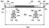
次に図3乃至図5に第2の実施形態となる本発明の雌コネクタ(以下、単にコネクタという)を示す。図3はコネクタ300の平面図、図4は図3のコネクタ300の正面図、図5は図3のコネクタ300の側面図を夫々示す。以下、図3乃至図5を参照して説明する。コネクタ300のハウジング302は絶縁性の樹脂から成形され、略直方体形状を呈する。ハウジング302の前面316には、矩形の横長の開口322が形成され、この開口322からハウジング302の内方に嵌合凹部304が形成されている。図4に最もよく示すように嵌合凹部304の略中央には、横方向に延びる上下2枚のプレート348、349が近接して、嵌合凹部304の後壁344から紙面に対し垂直方向に突設されている。上側のプレート348は下側のプレート349より僅かに長くなっている。各プレート348、349にはその長手方向に沿って複数のコンタクト340が所定の間隔で、互いのプレートの方に向いて配設されている。上側のプレートの両端部には電源用のコンタクトが2個づつ配置されている。 Next, FIGS. 3 to 5 show a female connector (hereinafter simply referred to as a connector) according to a second embodiment of the present invention. 3 is a plan view of the
ハウジング302の外側には、ハウジング302と同様の形状のシールド用の金属製のシェル306が外装されている。シェル306は前述の実施形態のシェル106と同様な形状なので、詳細な説明は省略するが主な相違点について以下に説明する。シェル306の上壁330には、その後端362近傍の左右両側に形成された開口365内に、前方に向け且つ内側のハウジング302の方に傾斜しているラッチアーム364が形成されている。このラッチアーム364は、ハウジング302がシェル306の後端362側からシェル306内に挿入されると、ハウジング302の上壁312の突起366と協働してハウジング302の後方への抜けが阻止される。 A
ハウジング302の後部両側には直方体のブロック382が一体に突設されている。ブロック382には、シェル306の後端362に突設された後方タブ384を受容するタブ溝382aが形成されており、ハウジング302をシェル306に装着したとき、後方タブ384がタブ溝382a内に入り込んで、ハウジング302の前方への移動を規制する。 A
また、シェル306の上壁330には、コ字状のスロット376により形成された舌片378が、ラッチアーム364近傍に2個ずつ向かい合わせに配置されている。他方ハウジング302の上壁312には舌片378に対向する位置に、両側に溝を有する断面T型の突起380が形成されている。舌片378は、この突起380の溝に両側から差し込まれて係止される。これによって、シェル306の上壁330がハウジング302の上壁312から浮き上がるのが阻止される。 Also, on the
第2の実施形態のコネクタ300は、前面316が図示しないパネルに接して取付けられる形式なので、先の実施形態の接片138(図1)に相当する構成がない。ばね接触片326は面板320から嵌合凹部304内に配列されており、下側については略等間隔に4個形成され、上側については両端部寄りに夫々2個づつ配置されている。上側の内側に位置する2個のばね接触片326の間には、シェル306の上壁330から、ハウジング302の前面316で湾曲して嵌合凹部304内に延びる内側延長部368が形成されている。内側延長部368の内面368aには係止突起370が嵌合凹部304内に突設されている。この係止突起370は、図示しない雄コネクタと嵌合する際に互いに嵌合状態を維持するロック部となる。 The
面板320の下部からハウジング302の下面に折り曲げられた曲げ部372には、舌片332が切り起こされて形成されている。各舌片332は、下側のばね接触片326の近傍に対応して配置されている。これらの舌片332は、下側のばね接触片326から基板に至る接地経路を形成する。また、舌片332が、面板320に近接し且つ面板320と一体的に複数形成されているので、相手方のコネクタが挿入される際にこじりが生じても、その力を複数の舌片332が分散して受けることとなり、耐こじり性が向上する。 A
シェル306の上壁330からは、ハウジング302の側壁314を覆う側壁308が折曲により形成されている。このシェル306の側壁308の下端308aには、前方寄りの部分に舌片310が、下方に突設されている。これらの舌片310は上側のばね接触片326から基板に至る接地経路を形成する。 From the
以上本発明の実施の形態について詳細に説明したが、前述のコネクタ100は、前面116に嵌合凹部104を有する、取付基板170に取付けられる絶縁性のハウジング102と、このハウジング102に保持されるコンタクト140と、ハウジング102の前面116を覆い相手方のコネクタと接地接続される面板120を有すると共に、上壁112及び側壁114を覆う本体156を有する金属製のシェル106とを備えたコネクタにおいて、本体156及び面板120に夫々接地接続用の舌片110、132を設けたことを特徴とする。 Although the embodiment of the present invention has been described in detail, the
これにより、コネクタ100は、面板120の上下の接地接続部分(ばね接触片)126から取付基板170に至る接地経路にばね接触片126の位置による差がなくなり、最短経路で取付基板に接地接続ができる。その結果、接地経路が大きなループを形成せず、接地経路のインダクタンスを小さくできるので、耐ノイズ性の向上が可能となる。 As a result, the
100、300 雌コネクタ
102、302 ハウジング
104、304 嵌合凹部
106、306 シェル
108、308 シェルの側壁
110、132、310、332 舌片
112、312 ハウジングの上壁
114、314 ハウジングの側壁
116、316 ハウジングの前面
120、320 面板
126、326 ばね接触片
130、330 シェルの上壁
140、340 コンタクト
170 基板100, 300
Claims (2)
Translated fromJapanese前記シェルが、少なくとも前記ハウジングの前面を覆う面板を有し、該面板には前記嵌合凹部の上側および下側に前記雄コネクタと接触する複数のばね接触片が配設されると共に前記面板の下側には前記下側のばね接触片と近接して前記基板に接地接続される複数の舌片が突設されていることを特徴とする雌コネクタ。An insulative housing for holding contacts in a generally rectangular fitting recess for receiving a male connector, and a metal shielding shell external to the housing, wherein the shell is attached to a substrate and the shell is mounted on the substrate. A female connector that is grounded to
The shell has a face plate that covers at least a front surface of the housing, and a plurality of spring contact pieces that are in contact with the male connector are provided on the face plate on the upper and lower sides of the fitting recess. A female connector having a plurality of tongues protrudingly provided on the lower side in close proximity to the lower spring contact pieces and grounded to the substrate.
Priority Applications (1)
| Application Number | Priority Date | Filing Date | Title |
|---|---|---|---|
| JP2004235914AJP2004319522A (en) | 2000-03-31 | 2004-08-13 | Female connector |
Applications Claiming Priority (2)
| Application Number | Priority Date | Filing Date | Title |
|---|---|---|---|
| JP2000097618 | 2000-03-31 | ||
| JP2004235914AJP2004319522A (en) | 2000-03-31 | 2004-08-13 | Female connector |
Related Parent Applications (1)
| Application Number | Title | Priority Date | Filing Date |
|---|---|---|---|
| JP2000298756ADivisionJP3678990B2 (en) | 2000-03-31 | 2000-09-29 | Electrical connector assembly and female connector |
Publications (1)
| Publication Number | Publication Date |
|---|---|
| JP2004319522Atrue JP2004319522A (en) | 2004-11-11 |
Family
ID=33477891
Family Applications (1)
| Application Number | Title | Priority Date | Filing Date |
|---|---|---|---|
| JP2004235914APendingJP2004319522A (en) | 2000-03-31 | 2004-08-13 | Female connector |
Country Status (1)
| Country | Link |
|---|---|
| JP (1) | JP2004319522A (en) |
Cited By (4)
| Publication number | Priority date | Publication date | Assignee | Title |
|---|---|---|---|---|
| JP2006228617A (en)* | 2005-02-18 | 2006-08-31 | Nippon Deikkusu:Kk | Plug and socket for speaker cable and connector for speaker cable by plug and socket |
| JP2007080560A (en)* | 2005-09-12 | 2007-03-29 | D D K Ltd | Electric connector |
| JP2007234488A (en)* | 2006-03-03 | 2007-09-13 | I-Pex Co Ltd | Connector device |
| US7297026B2 (en) | 2005-09-21 | 2007-11-20 | Japan Aviation Electronics Industry, Limited | Connector with a shell having a function of guiding insertion and removal of a mating connector |
- 2004
- 2004-08-13JPJP2004235914Apatent/JP2004319522A/enactivePending
Cited By (4)
| Publication number | Priority date | Publication date | Assignee | Title |
|---|---|---|---|---|
| JP2006228617A (en)* | 2005-02-18 | 2006-08-31 | Nippon Deikkusu:Kk | Plug and socket for speaker cable and connector for speaker cable by plug and socket |
| JP2007080560A (en)* | 2005-09-12 | 2007-03-29 | D D K Ltd | Electric connector |
| US7297026B2 (en) | 2005-09-21 | 2007-11-20 | Japan Aviation Electronics Industry, Limited | Connector with a shell having a function of guiding insertion and removal of a mating connector |
| JP2007234488A (en)* | 2006-03-03 | 2007-09-13 | I-Pex Co Ltd | Connector device |
Similar Documents
| Publication | Publication Date | Title |
|---|---|---|
| US7273397B2 (en) | Electrical connector having flexible mating portion | |
| US7422465B2 (en) | Electrical connector having flexible mating portion | |
| US6561849B2 (en) | Electrical connector having an improved outer conductive shell | |
| US7758380B2 (en) | Stacked electrical connector with improved shell for EMI protection | |
| US9106024B2 (en) | Electrical connector with a metal plate for preventing electromagnetic interference | |
| US6659791B1 (en) | Micro coaxial cable connector having latches for securely engaging with a complementary connector | |
| US20010034163A1 (en) | Battery connector | |
| US7416449B2 (en) | Electrical connector assembly with improved covers | |
| JPH11149957A (en) | Shielded connector with latch mechanism | |
| US10741970B1 (en) | Electrical connector and electrical connector assembly having the same | |
| JP2002231391A (en) | Shielding connector assembly | |
| TW201345076A (en) | Electric connector assembly | |
| US6210226B1 (en) | Electrical connector having enhanced sideward impact resisting structure | |
| US7229298B2 (en) | Electrical connector having an improved grounding path | |
| KR100694401B1 (en) | Electrical connector assembly | |
| US6554642B1 (en) | Electrical connector | |
| US6109969A (en) | Cable connector having improved EMI shields for securely grounding to a panel of a mating connector | |
| JP2001266994A (en) | Printed circuit board connector | |
| JP3801448B2 (en) | Shield connector assembly | |
| CN108306145B (en) | Electrical connector | |
| JP3678990B2 (en) | Electrical connector assembly and female connector | |
| JP3755652B2 (en) | Shield connector assembly | |
| US6746265B2 (en) | Electrical connector assembly and male connector used in the same | |
| JP2004319522A (en) | Female connector | |
| US20140308832A1 (en) | Electrical connector assembly having combination interface |
Legal Events
| Date | Code | Title | Description |
|---|---|---|---|
| A621 | Written request for application examination | Free format text:JAPANESE INTERMEDIATE CODE: A621 Effective date:20040813 | |
| A977 | Report on retrieval | Free format text:JAPANESE INTERMEDIATE CODE: A971007 Effective date:20060817 | |
| A131 | Notification of reasons for refusal | Free format text:JAPANESE INTERMEDIATE CODE: A131 Effective date:20060822 | |
| A521 | Written amendment | Effective date:20061020 Free format text:JAPANESE INTERMEDIATE CODE: A523 | |
| A131 | Notification of reasons for refusal | Effective date:20070403 Free format text:JAPANESE INTERMEDIATE CODE: A131 | |
| A521 | Written amendment | Effective date:20070531 Free format text:JAPANESE INTERMEDIATE CODE: A523 | |
| A02 | Decision of refusal | Free format text:JAPANESE INTERMEDIATE CODE: A02 Effective date:20071204 |