JP2004318891A - System and method for multiplexing reflections in a combined finger recognition and finger navigation module - Google Patents
System and method for multiplexing reflections in a combined finger recognition and finger navigation moduleDownload PDFInfo
- Publication number
- JP2004318891A JP2004318891AJP2004121381AJP2004121381AJP2004318891AJP 2004318891 AJP2004318891 AJP 2004318891AJP 2004121381 AJP2004121381 AJP 2004121381AJP 2004121381 AJP2004121381 AJP 2004121381AJP 2004318891 AJP2004318891 AJP 2004318891A
- Authority
- JP
- Japan
- Prior art keywords
- finger
- image
- mode
- swipe
- light
- Prior art date
- Legal status (The legal status is an assumption and is not a legal conclusion. Google has not performed a legal analysis and makes no representation as to the accuracy of the status listed.)
- Withdrawn
Links
Images


Classifications
- G—PHYSICS
- G06—COMPUTING OR CALCULATING; COUNTING
- G06F—ELECTRIC DIGITAL DATA PROCESSING
- G06F3/00—Input arrangements for transferring data to be processed into a form capable of being handled by the computer; Output arrangements for transferring data from processing unit to output unit, e.g. interface arrangements
- G06F3/01—Input arrangements or combined input and output arrangements for interaction between user and computer
- G06F3/03—Arrangements for converting the position or the displacement of a member into a coded form
- G06F3/0304—Detection arrangements using opto-electronic means
- G06F3/0317—Detection arrangements using opto-electronic means in co-operation with a patterned surface, e.g. absolute position or relative movement detection for an optical mouse or pen positioned with respect to a coded surface
- G—PHYSICS
- G06—COMPUTING OR CALCULATING; COUNTING
- G06V—IMAGE OR VIDEO RECOGNITION OR UNDERSTANDING
- G06V10/00—Arrangements for image or video recognition or understanding
- G06V10/20—Image preprocessing
- G06V10/26—Segmentation of patterns in the image field; Cutting or merging of image elements to establish the pattern region, e.g. clustering-based techniques; Detection of occlusion
- G—PHYSICS
- G06—COMPUTING OR CALCULATING; COUNTING
- G06F—ELECTRIC DIGITAL DATA PROCESSING
- G06F3/00—Input arrangements for transferring data to be processed into a form capable of being handled by the computer; Output arrangements for transferring data from processing unit to output unit, e.g. interface arrangements
- G06F3/01—Input arrangements or combined input and output arrangements for interaction between user and computer
- G06F3/03—Arrangements for converting the position or the displacement of a member into a coded form
- G06F3/033—Pointing devices displaced or positioned by the user, e.g. mice, trackballs, pens or joysticks; Accessories therefor
- G06F3/0354—Pointing devices displaced or positioned by the user, e.g. mice, trackballs, pens or joysticks; Accessories therefor with detection of 2D relative movements between the device, or an operating part thereof, and a plane or surface, e.g. 2D mice, trackballs, pens or pucks
- G06F3/03547—Touch pads, in which fingers can move on a surface
- G—PHYSICS
- G06—COMPUTING OR CALCULATING; COUNTING
- G06V—IMAGE OR VIDEO RECOGNITION OR UNDERSTANDING
- G06V40/00—Recognition of biometric, human-related or animal-related patterns in image or video data
- G06V40/10—Human or animal bodies, e.g. vehicle occupants or pedestrians; Body parts, e.g. hands
- G06V40/12—Fingerprints or palmprints
- G06V40/1335—Combining adjacent partial images (e.g. slices) to create a composite input or reference pattern; Tracking a sweeping finger movement
- G—PHYSICS
- G06—COMPUTING OR CALCULATING; COUNTING
- G06F—ELECTRIC DIGITAL DATA PROCESSING
- G06F2203/00—Indexing scheme relating to G06F3/00 - G06F3/048
- G06F2203/033—Indexing scheme relating to G06F3/033
- G06F2203/0338—Fingerprint track pad, i.e. fingerprint sensor used as pointing device tracking the fingertip image
Landscapes
- Engineering & Computer Science (AREA)
- Theoretical Computer Science (AREA)
- General Engineering & Computer Science (AREA)
- Physics & Mathematics (AREA)
- General Physics & Mathematics (AREA)
- Human Computer Interaction (AREA)
- Multimedia (AREA)
- Image Input (AREA)
Abstract
Translated fromJapaneseDescription
Translated fromJapanese本発明は、一般に、画像入力分野に関するものである。とりわけ、本発明は、ナビゲーション及び認識のため、指紋の画像を得て、処理を施すためのシステム及び方法に関するものである。 The present invention generally relates to the field of image input. More particularly, the present invention relates to systems and methods for obtaining and processing fingerprint images for navigation and recognition.
認証のための指紋の利用は、数世紀前まで遡ることが可能である。例えば、14世紀のペルシャでは、さまざまな政府の公文書に指紋(圧痕)が含まれており、ある政府高官は、2つの指紋が全く同じということはないという点に気づいていた。最近では、指紋は、生理的特性または行動特性に基づく個人の認証を表わす、バイオメトリクスとして既知の分野において重要な役割を果たしている。バイオメトリクスによって、犯罪捜査、施設への物理的出入り、及び、コンピュータ及び/またはコンピュータ・システムのデータへの電子的アクセスといった、いくつかの用途のための自動個人認証が可能になる。 The use of fingerprints for authentication can be traced back centuries ago. For example, in Persia in the 14th century, various government documents contained fingerprints (imprints), and one senior government official noticed that no two fingerprints were exactly the same. Recently, fingerprints have played an important role in the field known as biometrics, which represents the authentication of individuals based on physiological or behavioral characteristics. Biometrics allow for automatic personal identification for some applications, such as criminal investigations, physical access to facilities, and electronic access to data on computers and / or computer systems.
指紋は、現在では、従来行われていたように、紙に押し付けた指紋を得る中間ステップを必要とすることなく、ディジタル画像の形で直接得ることが可能である。ディジタル指紋は、記憶しておいて、後で、指紋強調及び照合用途において処理することが可能である。認識に十分な特徴を備えた指紋画像を入力するには、一定の解像度及び指先面積が必要になる。例えば、連邦捜査局(FBI)では、400dpiの解像度で、12×6mmの指先面積(センシングエリア)を推奨している。サイズ及びコストが重要な要素になる他の用途の場合、上記と同じか、それ未満の解像度で、より狭い指先面積を利用することが可能である。例えば、多くの用途では、300dpiの解像度で、9×12mmの指先面積が用いられてきた。しかし、より小面積及び/または低解像度の指紋画像入力用途では、指紋認証アルゴリズムの性能は、通常、入力される特徴の数が減少するために劣ることになる。 Fingerprints can now be obtained directly in the form of a digital image without the need for an intermediate step of obtaining a fingerprint pressed on paper, as has been done in the past. The digital fingerprint can be stored and later processed in fingerprint enhancement and verification applications. To input a fingerprint image having features sufficient for recognition, a certain resolution and a certain fingertip area are required. For example, the Federal Bureau of Investigation (FBI) recommends a fingertip area (sensing area) of 12 × 6 mm with a resolution of 400 dpi. For other applications where size and cost are important factors, it is possible to utilize a smaller fingertip area at the same or lower resolution as above. For example, many applications have used a 9 × 12 mm fingertip area at a resolution of 300 dpi. However, for smaller area and / or lower resolution fingerprint image input applications, the performance of the fingerprint authentication algorithm will typically be poor due to the reduced number of input features.
用途によっては、9×12mmの面積でさえ、指紋画像の入力専用にするのは望ましくない場合がある。例えば、携帯電話、ラップトップ・コンピュータ、携帯端末、電子マウス、または、他の電子装置の設計においては、装置自体を小型にし、同時に、より多くの機構を与えようとする傾向がある。従って、こうした電子装置に指認識機構を与えるためには、検知領域(センシングエリア)をできる限り小さくする必要がある。しかし、こうした電子装置に実装するのに十分なほど小さく、それにもかかわらず、十分な指認識アルゴリズム性能を可能にする指紋スキャナは、現在のところ得られない。 In some applications, it may not be desirable to dedicate even a 9 × 12 mm area for fingerprint image input. For example, in the design of mobile phones, laptop computers, mobile terminals, electronic mice, or other electronic devices, there is a tendency to reduce the size of the device itself while at the same time providing more features. Therefore, in order to provide a finger recognition mechanism to such an electronic device, it is necessary to make the sensing area (sensing area) as small as possible. However, there is currently no fingerprint scanner available that is small enough to be implemented in such electronic devices, yet nonetheless allows for sufficient finger recognition algorithm performance.
やはり、多くの電子装置によって得られるもう1つの機構は、スクリーン上におけるカーソルまたはポインタを制御するためのナビゲーション機構である。これまで、PC用途において最もよく知られているナビゲーション機構はマウスである。最近、一連の画像を移動の方向に相関させるトラッキング・アルゴリズムを利用して、ほぼいかなる任意の表面上においてもナビゲート可能な光学マウスが開発された。例えば、参考までに本明細書で全部が援用されている先行技術文献(例えば、特許文献1参照)には、マウス下の表面の空間的特徴を画像入力し、一連の画像を比較して、移動方向及び量を確認する光学マウスについての記載がある。さらに、参考までに本明細書で全部が援用されている先行技術文献(例えば、特許文献2参照)によれば、指の動きを検出して、その指の動きを、スクリーン上における対応するカーソルまたはポインタの動きに変換する光学フィンガ・ナビゲーション装置も開発されている。 Again, another mechanism provided by many electronic devices is a navigation mechanism for controlling a cursor or pointer on a screen. To date, the best known navigation mechanism in PC applications is the mouse. Recently, optical mice have been developed that can navigate on almost any surface using a tracking algorithm that correlates a series of images to the direction of movement. For example, in the prior art document (for example, see Patent Document 1), which is hereby incorporated by reference in its entirety, an image of a spatial feature of a surface under a mouse is input, and a series of images are compared. There is a description of an optical mouse that checks the direction and amount of movement. Further, according to the prior art document (for example, see Patent Document 2), which is entirely incorporated herein by reference, the movement of a finger is detected, and the movement of the finger is detected by a corresponding cursor on the screen. Alternatively, an optical finger navigation device that converts the movement into the movement of a pointer has been developed.
同じ電子装置に指認識及びフィンガ・ナビゲーションのための独立したセンシングエリアを配置するのは、コスト及びスペースの観点から非効率的である。しかし、指認識とフィンガ・ナビゲーションの両方を実施することが可能な指紋スキャナは現在のところ得られない。
従って、本発明の目的は、電子装置に組み込むのに十分なほど小さいサイズの単一センシングエリアを利用して、指認識とフィンガ・ナビゲーションを併せて実施する光学機構を提供することにある。本発明のもう1つの目的は、指認識とフィンガ・ナビゲーションの両方を実施し、同時に、小型電子装置及び/または携帯式電子装置における電力消費を最小限に抑えることが可能なコスト効率の良い画像化システムを提供することにある。 Accordingly, it is an object of the present invention to provide an optical mechanism that performs finger recognition and finger navigation in combination, utilizing a single sensing area small enough to be incorporated into an electronic device. Another object of the present invention is to provide both cost-effective image processing that can perform both finger recognition and finger navigation while minimizing power consumption in small and / or portable electronic devices. It is to provide an optimization system.
本発明のいくつかの実施態様によれば、少なくとも2つの異なる動作モードで指紋を画像入力し、指認識及びフィンガ・ナビゲーションの両方に応用できるようにするための装置が得られる。ユーザが指(親指又は足指)を押し当てるフィンガ・インターフェースのセンシングエリアが2つ以上の区画に分割される。各々の区画は、各々の光源によって別々に照射される。指で反射された光は、配列された光画像検知領域(受光領域)によって入力され、光源から光を照射することによって発する反射光を受光する。その照射する光源は、選択動作モードによって選択され、選択モードでの動作にとって必要なフィンガ・インターフェースのこれらの区画のみを照射する。その光は、光学画像検知領域で1つ以上の区画画像に対応する画像データとして入力される。その入力された画像データは少なくとも2つの異なるモードの1つでデータ処理をするため、光画像検知領域から出力される。 According to some embodiments of the present invention, there is provided an apparatus for imaging a fingerprint in at least two different modes of operation so that it may be applied to both finger recognition and finger navigation. The sensing area of the finger interface on which the user presses a finger (thumb or toe) is divided into two or more sections. Each compartment is illuminated separately by each light source. The light reflected by the finger is input through the arranged light image detection areas (light receiving areas), and receives reflected light emitted by irradiating light from a light source. The illuminating light source is selected by the selection mode of operation and illuminates only those sections of the finger interface required for operation in the selection mode. The light is input as image data corresponding to one or more section images in the optical image detection area. The input image data is output from the optical image detection area for data processing in one of at least two different modes.
本発明の他の実施態様によれば、少なくとも2つの異なる画像データ処理モードの中から所望のモードを選択するモード・スイッチを備えた画像入力システムが得られる。そのモード・スイッチは更に、少なくとも2つのモードのうち、1つのモードで画像入力システムが動作しているときに、所望の区画を照射するため、複数の光源のうちの1つ以上を選択する。その選択された光源に対応する画像検知領域から得られた画像データは、少なくとも2つのモードのうちの1つで画像データを処理するようにプログラムされたプロセッサに入力される。 According to another embodiment of the present invention, there is provided an image input system including a mode switch for selecting a desired mode from at least two different image data processing modes. The mode switch further selects one or more of the plurality of light sources to illuminate a desired section when the image input system is operating in one of at least two modes. Image data obtained from the image sensing area corresponding to the selected light source is input to a processor programmed to process the image data in one of at least two modes.
フィンガ・ナビゲーション・モードにおいて、画像データは、指が動く量及び方向を示すナビゲーション情報を確認するために、一連の画像を相関させることが可能なトラッキング・アルゴリズムを用いて処理される。その画像は、画像センサによって、入力された指紋のそれぞれの部分において、微少テクスチャ特徴(例えば、隆起線及び凹線)を用いて、相関される。 In the finger navigation mode, the image data is processed using a tracking algorithm capable of correlating a series of images to identify navigation information indicating the amount and direction of finger movement. The image is correlated by the image sensor at each portion of the input fingerprint using microtexture features (eg, ridges and depressions).
フィンガ・ナビゲーション・モードにおいて、画像データは、指紋の照合のための十分な数の微少テクスチャ特徴を有する指紋の一連の画像を形成するために、トラッキング・アルゴリズムと一連の画像を結合(合成)するステッチング・アルゴリズムとの両方を用いて処理される。そのステッチング・アルゴリズムは、トラッキング・アルゴリズムによって、決定されるナビゲーションを使用し、順次画像間のオーバラップを決定する。 In the finger navigation mode, the image data combines a series of images with a tracking algorithm to form a series of fingerprint images having a sufficient number of microtextured features for fingerprint matching. It is processed using both the stitching algorithm. The stitching algorithm uses the navigation determined by the tracking algorithm to determine the overlap between sequential images.
他の実施態様において、画像入力システムは、スタイラス・モードのような他のタイプの光学ナビゲーション応用例のための追加モードで動作することが可能である。スタイラス・モードの場合、指の一連の画像を表わす画像データから抽出されるナビゲーション情報を利用して、所望の英字、数、または、句読記号に関連したユーザによってなされるフィンガ・ストロークが決定される。画像化システムのもう1つの動作モードは、光源がメッセージ表示灯として用いられる、明滅モードである。 In other embodiments, the image input system can operate in additional modes for other types of optical navigation applications, such as stylus mode. In the stylus mode, navigation information extracted from image data representing a series of images of a finger is used to determine a user's finger stroke associated with a desired letter, number, or punctuation mark. . Another mode of operation of the imaging system is a blinking mode, where the light source is used as a message indicator.
フィンガ・インターフェースのセンシングエリアの多重照射は小型及び/又は携帯式電子装置において、電力消費量を最小限にすることによって、画像化システムの性能を改良する。さらに、本発明によれば、上述のものに加えて、あるいは、それらの代わりに、他の特徴及び利点を備えた実施態様も得られる。これらの特徴及び利点の多くは、添付の図面に関連した下記の説明から明らかになるであろう。 Multiple illumination of the sensing area of the finger interface improves the performance of the imaging system by minimizing power consumption in small and / or portable electronic devices. In addition, the present invention provides embodiments with other features and advantages in addition to or in place of those described above. Many of these features and advantages will be apparent from the description below with reference to the accompanying drawings.
開示の発明は、本発明の重要な見本となる実施態様を示す、参考までに明細書に組み込まれた、添付の図面に関連して説明されることになる。 The disclosed invention will be described with reference to the accompanying drawings, which are incorporated by reference, and which illustrate important exemplary embodiments of the invention.
本出願の数多くの新規の教示が、特定の典型的な実施態様に関連して解説される。ただし、云うまでもないが、これらの実施態様によって示されるのは、本明細書における新規の教示の数多くある有用な用途のほんの数例にすぎない。一般に、本明細書でなされる説明は、必ずしも、請求の範囲に記載されているさまざまな発明の任意のどれかについて限界を設定するものではない。さらに、説明の中には、本発明のある特徴には当てはまるが、他の特徴には当てはまらないというものもある。 Numerous novel teachings of the present application are described with reference to certain exemplary embodiments. It should be understood, however, that these embodiments are merely illustrative of the many useful applications of the novel teachings herein. In general, statements made in this specification do not necessarily set limits on any of the various claimed inventions. Furthermore, some descriptions may apply to certain features of the invention but not to others.
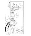
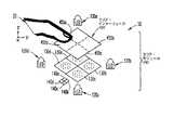
図1には、1つがフィンガ・ナビゲーション・モードで、もう1つが指認識モードという、少なくとも2つの異なるモードで動作可能な画像入力システム10が例示されている。画像入力システム10の用途によっては、他のモードも可能である。例えば、画像入力システム10は、フィンガ・ストロークを利用して、簡便かつ効率のよいやり方で、書かれた英字、数字、句読記号、及び、他の書かれた伝達形態を表わす、スタイラス・モードで動作するようにプログラムすることが可能である。画像入力システム10には、今後はスワイプ・モジュール100と呼ぶことにする、人間の指20の画像を表わした画像データ50を入力するための装置と、少なくとも2つの異なるモードの1つで画像データ50を処理するための画像処理システム200が含まれている。以下で用いられるように、「指」という用語には、人間の手または足の任意の指(手指、親指、または、足指)が含まれる。 FIG. 1 illustrates an
スワイプ・モジュール100には、ユーザがその上に指20を押し付けて、指20を動かす上面115を備えたスワイプ・インターフェース110が含まれている。上面115は、フラットにすることもできるが、わずかに湾曲させることができるのが望ましい。例えば、凸状に湾曲させると、上面115の検知領域(指の画像を捉えることのできるセンシングエリア)を拡大するのに役立つ。センシングエリアは、上面115に押し付けられた指20の画像を入力するために焦点が合わせられた、上面115の一部である。望ましい実施態様の場合、センシングエリアには、スワイプ・インターフェース110の上面115全体が含まれる。スワイプ・インターフェース110は、スワイプ・インターフェース110の上面115を照射する光源120から放出される光に対して透明な、ガラスまたは他の耐摩耗性材料から形成することが可能である。 The
実施態様の1つでは、スワイプ・インターフェース110は、少なくとも1つの方向の寸法において人間の指の先端領域より小さいセンシングエリアを設けるため、細長い形状をなしている。人間の指の先端領域は、従来の9×12mmのセンシングエリアと定義される。図1に示す軸を利用すると、ある実施態様の場合、スワイプ・インターフェース110は、y方向に細長い。一例として、スワイプ・インターフェース110は、y方向において約7〜9mmで、x方向において1mmである。他の実施態様の場合、スワイプ・インターフェース110は、領域拡大という代償を払ってでも、性能を向上させることができるように、領域によっては2mmまでといったように、x方向において拡大することが可能なものもある。 In one embodiment,
図1に示すように、ユーザの指20は、指先から指20の付け根までの指20の全長がx方向に向き、指20の両側間にわたる指20の幅がy方向に向くようにして、スワイプ・インターフェース上に配置される。従って、指20の全長は、図示のように、指20の幅にわたって指20の先端部分の画像を入力するため、スワイプ・インターフェースの長手方向に直交している。ただし、云うまでもなく、他の実施態様には、スワイプ・インターフェース110の長手方向に対して、指20の全長をスワイプ・インターフェースの軸方向(長手方向)に任意の位置まで回転させることが可能なものもある。例えば、指20の全長は、スワイプ・インターフェース110の長手方向に対して平行にすることも可能である。 As shown in FIG. 1, the user's
光源120は、任意の適合する電磁放射線(光125)源とすることが可能である。例えば、制限するわけではないが、光源120は、単一の発光ダイオード(LED)、スワイプ・インターフェース表面115の異なる部分を照射するように配置された複数のLED、または、所望の平均強度で光125を放出するように設計されたLEDアレイとすることが可能である。光源125から放出される光125の波長は、人間の皮膚からの光125の反射を最大にし、反射光128と望ましくない光信号とを識別できるように選択される。さらに、光125の波長は、ユーザまたはメーカの選好に基づいて選択することが可能である。例えば、メーカによっては、特定の用途において赤色光よりも青色光を選択する場合があり得る。光源120は、安定した照射量または可変照射量の連続モードで「オン」状態にするか、あるいは、光源120をパルス動作でオン/オフして、平均光量のサーボ制御により露光を制御する、デューティ・サイクル・モードで「オン」状態にすることが可能である。照射強度は、任意の既知技法を用いて制御することが可能である。
照射光学素子(不図示)を利用して、所望の入射角でスワイプ・インターフェース110に光125を向けることも可能である。例えば、照射光学素子は、LEDドーム・レンズ、または、光の損失量を最小限に抑えて、スワイプ・インターフェース110に光125を送る光パイプから構成することが可能である。当該技術において既知のように、不透明材料を照射するのに望ましい入射角は、5〜20度の範囲内のかすめ角(グレージング角)である。この範囲の入射角であれば、画像入力される物体に固有の構造特徴を表わした画像データのS/N比が高くなる。しかし、皮膚の透明性のために、ユーザの指20の画像を表わす画像データ50を十分に入力するのに、こうした斜角は必要ではない。従って、入射角の選択は、主として、用いられるLEDの数及びタイプ、z方向におけるスワイプ・モジュール100の厚さ、及び、用いられる光学素子(照射及び画像転送)といった、スワイプ・モジュール100の設計によって決まる。 Illumination optics (not shown) can be used to direct light 125 to swipe
指20の先端をスワイプ・インターフェース110の上面115に押し付けると、微小テクスチャ特徴と総称される、皮膚の隆線(稜線)及び凹線(谷)が、上面115の平面において観測できる。画像転送光学素子130によって、それらの微小テクスチャ特徴から反射した光128は、CCD(電荷結合素子)、CMOS−APS(相補型金属酸化膜半導体 − 活性ピクセル・センサ)、または、当該技術において既知の他の任意のタイプの光センサとすることが可能な、光画像センサ140の一部をなす光検出器アレイに送られる。光画像センサ140は、拡大/縮小機構を併用することによって、シリコン領域を縮小することができるので、熱または容量性画像センサよりも望ましい。熱及び容量性画像センサは、一般に、検知領域と同等のサイズのシリコン領域を必要とする。さらに、容量性画像センサは、静電気放電に影響されやすい可能性があり、このため、S/N比が低下し、従って、画像が劣化する可能性がある。 When the tip of the
光画像センサ140は、各光検出器において測定される反射光128の強度を表わした画像データ50の形で、微小テクスチャ特徴の画像を得る。各光検出器によって、画像の画素(ピクセル)が入力され、全てのピクセルを組み合わせて、完全な画像が形成される。光検出器は、例えば、スワイプ・インターフェースの細長い方向に対して平行な細長いアレイをなすように配列されたフォトダイオードまたはフォトトランジスタとすることが可能である。例えば、図1に示すように、スワイプ・インターフェース110及びセンサ140は、両方とも、y方向に細長い。細長いアレイのサイズは、光学素子の倍率によって決まる。例えば、ある実施態様の場合、光学素子の倍率は、1:3の比率で1未満である。従って、センシングエリア(上面115)のサイズが9mm×1mmの場合、センサ140のサイズは、3mm×0.3mmしか必要ないことになる。指先20の特徴は、人間の裸眼で検分するのに十分な大きさがあるので、センサ140のコストを低減し、さらに、スワイプ・モジュール100のサイズも縮小するため、1未満の倍率を用いて、センサ140領域を縮小することが可能である。ただし、云うまでもないが、スワイプ・モジュール100のサイズ制約条件及びメーカの選好に従って、1未満、ほぼ1、または、1を超える他の倍率を利用することも可能である。 The
各光検出器は、5〜60μm角の感光領域を備えており、光検出器間の間隔は、センサ140の所望の空間解像度を実現するように設計されている。例えば、3mm×0.3mmのピクセル領域上において、9mm×1mmの指センシングエリアで400dpiの解像度を実現するには、21μm×21μmのサイズの、114×16個の光検出器が必要になる。所望の解像度に制限されることなく、光検出器のサイズ、及び、光検出器間の間隔は、画像の微小テクスチャ特徴毎に少なくとも1つの(できれば、2つ以上の)光検出器を備えるように構成されており、光検出器アレイの全体サイズは、いくつかの微小テクスチャ特徴を備えた画像を入力するのに十分な大きさである。 Each photodetector has a 5-60 μm square photosensitive area, and the spacing between the photodetectors is designed to achieve the desired spatial resolution of the
画像センサ140は、少なくとも2つの異なるモードの少なくとも1つで、画像データ50を処理することが可能な画像処理システム200内のプロセッサ210に画像データ50(例えば、生ピクセル値)を供給する。各モード毎に、個別プロセッサ210を利用することもできるし、あるいは、1つのプロセッサ210に、全モードで動作するようにプログラムすることも可能である。プロセッサ210は、任意のマイクロプロセッサ、マイクロコントローラ、または、選択されたモードで画像データ50の処理が可能な他の処理装置とすることが可能であり、画像センサ140と同じチップに埋め込むことも可能である。モード・スイッチ220は、さらに詳細に後述するように、異なるモード間で選択を行い、センサ140の露光時間、フレームレート、及び、光源120の照射強度を制御する。モード・スイッチ220は、ユーザの要望する用途に基づいて、ユーザがトグルすることもできるし、あるいは、タスクが完了するとトグルするようにプリセットすることもできるし、あるいは、その両方のやり方でトグルすることも可能である。例えば、実施態様の1つにおいて、モード・スイッチ220は、指認識モードに初期設定し、指紋の認証がなされると、自動的にトグルして、フィンガ・ナビゲーション・モードになるようにすることが可能である。
上述のように、モード・スイッチ220によってあるモードまたは別のモードを選択すると、プロセッサ210による画像データ50の処理方法が決まる。さらに、センサ140の露光時間は、選択されたモードによって変動する可能性がある。例えば、フィンガ・ナビゲーション・モードの場合、ユーザは、スワイプ・インターフェース110上において、指認識モードの場合よりも素早く、不規則に指を動かす可能性があり、画像により多くの迷光を入り込ませることになる。この場合、モード・スイッチ220によって、センサ140の露光時間を短縮することによって、検出される迷光の量、従って、画像内におけるノイズ量を低減させることが可能である。 As described above, the selection of one mode or another by the
露光時間に加えて、または、その代わりに、モード・スイッチ220は、選択モードに従って、光源120から放出される光125の強度を制御することも可能である。例えば、指認識モードの場合、モード・スイッチ220は、フィンガ・ナビゲーション・モードの場合の照射強度に比べて、照射強度を増すことによって、S/N比を高め、指紋照合の正確度を向上させることが可能である。他の実施態様の場合、スワイプ・モジュール110は、ユーザの指がスワイプ・モジュール110に係合していない場合には、画像データ50の生成を中断し、光源120によって放出される光の強度を弱める「一時停止」機能を実施することが可能である。スワイプ・モジュール100は、反射光128が、たとえ存在したとしても、反射表面(すなわち、指20)が遠すぎるか、または、単純に視野内にないために、同じ強度で光検出器に達しなくなると、「一時停止」機能を開始することが可能である。非常に明るい環境であっても、「一時停止」機能は、光検出器の出力がほぼ一様になるのに応答して、開始することが可能である。 In addition to or instead of the exposure time, the
さらに、モード・スイッチ220は、センサが、選択されているモードに従って、一連の画像を表わした画像データ・セットを生成するフレームレートを制御することが可能である。例えば、指認識モードの場合、ユーザは、一般に、フィンガ・ナビゲーション・モードの場合よりもゆっくりと指20を走らせる。さらに、指認識モードの場合には、一連の画像にステッチをかけて(合成して)、完全な画像が形成されるが、フィンガ・ナビゲーション・モードの場合には、一連の画像を比較して、動きが確認される。従って、指認識モードにおける一連の画像間のオーバラップは、フィンガ・ナビゲーション・モードと比較して、最小になるようにしさえすればよい。一例を挙げると、指認識モードにおいて、ユーザが、幅1mmのセンシングエリアで、毎秒25mm指25を動かすと、指紋の完全な画像を入力するのに、毎秒26フレームのフレームレートで十分である。フィンガ・ナビゲーション・モードの場合には、毎秒500フレームまでのフレームレートが必要になる可能性がある。 Further, the
画像入力システム10は、単一電子装置内または複数電子装置内に含むことが可能である。例えば、スワイプ・モジュール100は、マウスのような遠隔電子装置に実装することが可能であり、一方、画像処理システム200は、マウスに対するインターフェースを備えたパーソナル・コンピュータに実装することが可能である。もう1つの例として、スワイプ・モジュール100及び画像処理システム200は、両方とも、携帯電話、ラップトップ・コンピュータ、または、PDAのような、小型電子装置及び/または携帯式電子装置に実装することが可能である。云うまでもないが、画像入力システム10が完全に単一電子装置内に実装される場合には、画像処理システム200は、スワイプ・モジュール100内に組み込むか、スワイプ・モジュール100に接続することが可能である。
スワイプ・モジュール100は、電子装置の要件に基づくz方向の厚さを備えている。例えば、多くの電子装置は、5mm未満の厚さを命じている。電子装置の厚さ仕様の範囲内においてスワイプ・モジュール100を製作するため、光路を折り返すか、または、光学素子のサイズを縮小するためのさまざまな技法を利用することが可能である。 The
図2には、折り返し(屈曲)光学素子の一例が示されている。図2には、典型的なスワイプ・モジュール100の絵画的表現による拡大略側面図が例示されている。LED120から放出される光125は、結合レンズ150によってプリズム155に結合され、プリズム155によって、所望の入射角でスワイプ・インターフェース110に送り込まれる。光125は、プリズム155の形状及び入射角に応じて、内面全反射(TIR=Total Internal Reflection)メカニズムを用いて送ることが可能である。他の実施態様の場合、光125は、反射光メカニズムを利用して送ることが可能である。図2の場合、光125は、プリズム155の第1の表面158を通過し、屈折によって、所望の入射角でスワイプ・インターフェース110の上面115に向かう。スワイプ・インターフェース110の表面115に押し付けられた指20からの反射光128は、プリズム155の第1の表面158で内面反射して、プリズム155の第2の表面159を通過する。 FIG. 2 shows an example of a folded (bent) optical element. FIG. 2 illustrates an enlarged schematic side view of a
プリズム155から出射する反射光128は、スワイプ・インターフェース110の長手方向に対して直交するx方向に進行して、拡大/縮小光学素子130を通過し、拡大/縮小光学素子130によって、もう1つのプリズム135に送られる。光128は、プリズム135によって、表面138で内面反射され、センサ140に対してz方向に向け直される。z方向に従来からある光学素子を利用する代わりに、x方向に折り返し光学素子を利用することによって、z方向におけるスワイプ・モジュール110の厚さを薄くすることが可能になる。もちろん、照明用の光学素子150及び/または画像を転送するための光学素子130において、アパーチャ及びレンズといった追加光学コンポーネントを利用することも可能である。さらに、図2に示す光学構成の代わりに、他の光学構成を利用して、光路を折り返すことも可能である。 The reflected light 128 exiting the
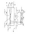
図3A及び3Bには、スワイプ・モジュール100の厚さ許容差内に収まるように光学素子のサイズを縮小する例の1つが例示されている。図3A及び3Bは、典型的なスワイプ・モジュール100の拡大側面図である。LED120から放出された光125は、結合レンズ150によってプリズム155に送られる。結合レンズ150には、LED120から狭い角度で発散する光125をコリメートすることが可能な対向する凸面が含まれている。スワイプ・モジュール100内におけるプリズム155の形状及び位置は、光が反射されるように、所望の入射角でスワイプ・インターフェース110に光を送るか、あるいは、スワイプ・インターフェース110内で多重の内面全反射を生じるように、スワイプ・インターフェース110に光125を送るように設計されるが、後者が例示される。 3A and 3B illustrate one example of reducing the size of an optical element to fall within the thickness tolerance of the
スワイプ・インターフェース110内で多重のTIRを実現するため、スワイプ・インターフェース110の上面115に直交する内部側面112に吸光材料をコーティングして、側面で反射光を吸収するのが望ましい。他の実施態様には、内部側面112を鏡面仕上げにすることが可能なものもある。光125は、光125の全内面反射を生じさせるため、スワイプ・インターフェース110材料の臨界角を超える入射角で上面115に送り込まれる。上面115からの内面全反射光125は、光125の別の内面全反射を生じさせるため、臨界角を超える入射角で、上面115と平行な底面118に送られる。スワイプ・インターフェース110の厚さ119は、より薄いスワイプ・モジュール100(例えば、2mm)を実現可能とするため、約0.5〜1mmになる。 To achieve multiple TIRs within the
指20からの反射光128は、スワイプ・インターフェース110の底面118を透過し、マイクロレンズ・アレイ170によって、光検出器アレイ145を備える画像入力センサ140に集束させられる。スワイプ・モジュール100の基板180上には、LED120、ドームの状レンズ150、及び、画像入力センサ140が形成されている。 The reflected light 128 from the
図3Bに示すように、マイクロレンズ・アレイ170内の各マイクロレンズ175a、175b、175cは、それぞれ、光検出器の1つ145a、145b、145cと1対1で結合されている。例えば、マイクロレンズ175aは、指紋25の一部(例えば、指紋の隆線25aまたは指紋の凹線25b)からの反射光128を対応する光検出器145aに集束させる。各光検出器145のサイズは、それぞれ、各光検出器145a、145b、145cの視野(FOV=Field Of View)190a、190b、190cを制限して、FOV190と隣接マイクロレンズ175が重なり合わないように選択される。 As shown in FIG. 3B, each microlens 175a, 175b, 175c in
処理モードに応じて、光検出器アレイをなす光検出器145の全て、または、光検出器145の一部だけから画像データを得ることが可能である。例えば、指認識モードの場合、指紋25の完全な画像を入力するには、9mm×1mmのセンシングエリア全体が必要になる。しかし、フィンガ・ナビゲーション・モードの場合には、動きの方向を確認するのに、ほんのわずかな指紋25の特徴だけしか必要とされないし、多くの場合、指20は、9mm×1mmの全センシングエリアに位置しているわけではない。従って、フィンガ・ナビゲーション・モードの場合、画像データは、指20に接触しているスワイプ・インターフェース110領域からの光を検出する、光検出器145の一部から取得しさえすればよい可能性がある。 Depending on the processing mode, image data can be obtained from all of the
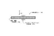
図4に示すように、フィンガ・ナビゲーションに必要な光検出器145の数を減らし、同時に、指の動きを確認するのに十分な画像データを入力するため、光検出器アレイ148の中心部におけるより広い検知領域をフィンガ・ナビゲーションのために提供するように、光検出器アレイ148を変更することが可能である。図4において、フィンガ・ナビゲーション・モードの場合、スワイプ・インターフェースにおける指の位置は、主として、センシングエリアの長手方向(y方向)の中心部にあるものと仮定する。また、指認識モードでは、指の一部が、センシングエリアの長手方向の中心部に位置するものと仮定するが、図14及び15に関連してさらに詳細に後述するように、その中心部分を利用して、フィンガ・ナビゲーション情報を取得することによって、一連の画像のステッチング(合成)が可能になる。 As shown in FIG. 4, in order to reduce the number of
従って、図4に示す光検出器145の構成において、対応するスワイプ・インターフェース110(不図示)の一般的なサイズは9mm×1mmであるが、スワイプ・インターフェースの中心領域は、2mm×2mmの中心領域が得られるように、x方向に拡大されている。中心領域は、フィンガ・ナビゲーションに利用される。これに応じて、センサ140の中心領域(点線で示された)も、スワイプ・モジュールの拡大中心領域からの光を検出するため、x方向に拡大されている。400dpiの解像度は、1mm当たり約16の光検出器に対応し、これは、144×16の指認識光検出器145e(黒の実線内に示された)、及び、光検出器アレイ148の中心領域における32×32のフィンガ・ナビゲーション光検出器145d(点線内に示された)に相当する。 Thus, in the configuration of the
異なるモード(例えば、指認識及びフィンガ・ナビゲーション)について、センサの異なる領域及び検知領域の異なる部分の利用を円滑にするため、複数光源及び/または複数センサを利用し、選択動作モードに従って、複数の異なる領域のうち、必要な指領域を照射し、画像入力することが可能である。図5A及び5Bには、選択されたモードに基づいて、スワイプ・インターフェース110の照射を多重化することが可能なスワイプ・モジュール10を備えた画像入力システム10の一例の概略が示されている。スワイプ・インターフェース110は、図示のように、y方向において3つの区画110a、110b、110cに分割されている。スワイプ・インターフェース110は、さらに図示のように、3つのLED120a、120b、120cによって照射される。照射は、LED120aがスワイプ・インターフェースの第1の区画110aだけを照射し、LED120bが第2の区画110bだけを照射し、LED120cが第3の区画110cだけを照射するようにアライメントがとられる。照射光学素子(光源からの光を被照射領域に導くための光学系)は、簡略化のため示されていない。しかし、云うまでもないが、各LED120a〜120c毎に独立した照射光学素子を利用して、各LED120a〜120cからの光をLED120a〜120cに関連したスワイプ・インターフェース110のそれぞれの区画110a、110b、110cに向けることが可能である。 For different modes (eg, finger recognition and finger navigation), multiple light sources and / or multiple sensors may be used to facilitate the use of different areas of the sensor and different portions of the sensing area, and multiple modes according to the selected mode of operation. It is possible to irradiate a necessary finger area among different areas and input an image. FIGS. 5A and 5B schematically illustrate an example of an
照射された指領域は、画像転送光学素子130a、130b、130cを利用して、画像入力することが可能である。画像転送光学素子130a、130b、130cは、さらに、スワイプ・インターフェース110の個別に照射される各区画110a、110b、110cが、それぞれ、対応する検知領域(受光領域)140a、140b、140cで画像入力されるように、y方向及びz方向においてもアライメントがとられる。検知領域140a、140b、140cは、単一センサに含むこともできるし、あるいは、検知領域140a、140b、140cは、図5Bに示すように、回路設計の制約条件に従って分離された3つのセンサとすることも可能である。中心の検知領域140b、及び、中心の区画110bは、図4に関連して上述のように、x方向に拡大することも可能である。 The image of the irradiated finger area can be input using the image transfer
個別センサ(互いに独立したセンサ)を利用する場合、異なるセンサ間の間隔は、光学素子の設計を単純化し、指認識モードにおいて完全な画像を保証するように設計される。例えば、スワイプ・インターフェース110の面積が9×1mmで、スワイプ・インターフェース110の各区画110a、110b、及び、110cが3×1mmの場合、各検知領域140a、140b、及び、140cのエリアは1×0.3mmとし、検知領域140a、140b、及び、140c間の間隔は0.25〜1mmとすることが可能である。実施態様によっては、幾何学的関係が分っている限りにおいて、検知領域140a、140b、及び、140c間の間隔に起因する入力画像のギャップを許容可能なものもある。他の実施態様では、複数の入力画像間でオーバラップしていることが、指認識モードにおけるステッチングを容易にするのに望ましい場合もあり得る。 When utilizing individual sensors (sensors independent of one another), the spacing between the different sensors is designed to simplify the design of the optics and ensure a perfect image in the finger recognition mode. For example, when the area of the
スワイプ・インターフェース110の3つの個別区画110a、110b、及び、110c、及び、3つの個別検知領域140a、140b、及び、140cが示されているが、もちろん、スワイプ・インターフェース110は、それぞれ、単一センサの個別領域または個別センサによって画像化可能な、任意の数の区画に分割することが可能である。利用される区画110a、110b、及び、110cの数が増すほど、区画サイズの縮小に比例して、1つの区画の照射に必要な光の強度が低下するため、必要とされる電力量が減少する。電力消費の減少は、小型電子装置及び/または携帯用電子装置において重要な設計パラメータである。例えば、蓄電池による電力供給を受ける携帯電話、PDA、及び、ラップトップ・コンピュータの場合、電力消費の減少によって蓄電池の寿命が延びることになる。 Although three
しかし、区画数が増すと、センサからピクセル値を読み取り、画像データを処理する上において、照射及び画像転送光学素子の複雑性も増す可能性がある。さらに、区画数が増すにつれて、各LEDによって照射されるセンシングエリアが縮小し、LED数が増大するので、照射設計は、より困難になり、いっそうコストがかさむことになる。 However, as the number of partitions increases, the complexity of the illumination and image transfer optics in reading pixel values from the sensor and processing image data may also increase. In addition, as the number of sections increases, the sensing area illuminated by each LED shrinks and the number of LEDs increases, making illumination design more difficult and more costly.
その他の実施態様の場合、照射は、スワイプ・インターフェースにおける指領域全体の画像を順次入力するように設計可能である。例えば、LED120b及び120cがオフ状態にある間,LED120aを「オン」にして、検知領域140aに画像化される第1の区画110aだけを照射することが可能である。検知領域140aからピクセル値を読み取って、記憶することが可能である。その後、LED120aを「オフ」にして、LED120bを「オン」にし、検知領域140bに画像入力される第2の区画110bだけを照射することが可能である。検知領域140bからピクセル値を読み取って、検知領域140aから前回入力した画像とのステッチングを施し、結果生じるステッチのかかった画像を記憶することが可能である。最後に、LED120bを「オフ」にして、LED120cを「オン」にし、同様のやり方で画像の残りが入力される。順次区画照射のタイミングは、区画された個々の画像間において目立った指の動きが、ほとんど乃至全く生じないように設定される。画像の順次入力では、一度に1つのLED120だけしか利用しないことによって、電力消費が減少する。 In other embodiments, the illumination can be designed to sequentially input images of the entire finger area in the swipe interface. For example, while the
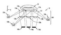
照射の多重化は、指紋の一部の画像だけしか入力せず、指紋の1つの連続した画像を形成するのに、指の移動を必要とする細長いスワイプ・モジュールにとってだけでなく、指の移動を必要とせずに、指紋全体の画像を入力するエリア・モジュールにとっても実行可能なオプションである。例えば、図5Cには、エリア・インターフェース455の多重化照射を実施するエリア・モジュールが示されている。 The multiplexing of the irradiation is not only for the elongated swipe module which requires the movement of the finger to input only a partial image of the fingerprint and to form one continuous image of the fingerprint, but also the movement of the finger. Is also a viable option for the area module to input an image of the entire fingerprint without the need for. For example, FIG. 5C illustrates an area module that performs multiplexed illumination of the
エリア・インターフェース455の検知領域は、図5Cに示されるように、x及びy方向において4つの区画に分割されている。4つのLED120a〜120dは、各LED毎に、それぞれ、エリア・インターフェース455の区画455a〜455dの1つを照射するようにして、エリア・インターフェース455を照射する。照射は、LED120aがエリア・インターフェース455の第1の区画455aだけを照射し、LED120bがエリア・インターフェース455の第2の区画455bだけを照射し、LED120cがエリア・インターフェース455の第3の区画455cだけを照射し、LED120dがエリア・インターフェース455の第4の区画455dだけを照射するようにアライメントがとられる。照射光学素子は、簡略化のため示されていない。しかし、云うまでもないが、各LED120a〜120d毎に独立した照射光学素子を利用して、各LED120a〜120dからの光をLED120a〜120dに関連したエリア・インターフェース455のそれぞれの区画455a〜455dに導くことが可能である。 The detection area of the
照射された指領域は、画像転送光学素子130a、130b、130c、及び、130dを利用して、画像化することが可能である。画像転送光学素子130a、130b、130c、及び、130dは、さらに、エリア・インターフェース455の個別に照射される各区画455a、455b、455c、及び、455dが、検知領域140a、140b、140c、及び、140dで画像入力されるように、x方向、y方向及びz方向においてもアライメントがとられる。検知領域140a、140b、140c、及び、140dは、個別センサとすることもできるし、あるいは、各区画の画像を入力する個別の領域を備えた単一のセンサとすることも可能である。スワイプ・モジュールに関連して上述のように、選択モードに従って、一度に1つ以上の区画455a、455b、455c、または、455dを照射することも可能である。 The irradiated finger region can be imaged using the image transfer
次に、図6A及び6Bを参照すると、個別センサまたは単一センサの個別領域への多重化照射によって、スワイプ・モジュール100のサイズがさらに縮小される。図6Aに示すように、y方向の幅が3mmの単一センサに対して、スワイプ・インターフェースのy方向における細長いセンシングエリア(例えば、9mm幅のセンシングエリアとして示された)からの光を集束させるため、光学素子からセンサまでの焦点距離は、z方向における光学素子とセンサとの間隔が「X」mmになることを必要とする。図6Bに示すように、9mmのセンシングエリアを、各区画毎に、それぞれの区画からの光をそれぞれの1mm幅センサに向けるための個別光学素子を備えた、3つの個別の3mm幅区画に分割することによって、z方向における光学素子と検知領域との間隔が1/3に短縮される。従って、図6Bに示すように、光学素子と検知領域との間隔はX/3mmになる。z方向における光学素子と検知領域との間隔が短縮されると、スワイプ・モジュール100の厚さ(z方向における)が2/3に減少する。このサイズの縮小は、電子マウス、携帯電話、PDA、及び、ラップトップ・コンピュータのような、小型電子装置及び/または携帯式電子装置にフィンガ・ナビゲーション及び指認識機能を導入する上において、重要な利点である。 6A and 6B, the size of the
図7Aは、本発明の画像入力システム10の典型的なハードウェア及び処理コンポーネントを例示したブロック図である。画像入力システム10には、それに投射された画像を入力して、その画像を表わしたアナログ信号345を発生する光検出器アレイ148を備えたセンサ140が含まれている。行デコーダ310及び列デコーダ320は、光検出器アレイ148の行及び列を選択し、ピクセル値を表わしたアナログ信号345を読み取って、光検出器をリセットする。列増幅器330は、アナログ・ディジタル変換器(ADC)350によってアナログ信号345を対応するディジタル信号355に変換する前に、アナログ信号345を増幅して、プログラマブル利得制御装置340に供給する。ADC350は、指認識モードの場合、約25フレーム/秒の速度で動作可能な、また、フィンガ・ナビゲーション・モードの場合には、500フレーム/秒の速度で動作可能な、6ビット、8ビット、または、10ビットADCとすることが可能である。 FIG. 7A is a block diagram illustrating exemplary hardware and processing components of the
画像入力システム10には、さらに、ディジタル信号355の処理に適したプロセッサ・モードを選択するためのモード・スイッチ220が含まれている。上述のように、モード・スイッチ220は、さらに、画像タイミング制御回路要素360を介して、センサ140のフレームレート及び露光時間(シャッタ速度)を制御する。フィンガ・ナビゲーション・モードの場合、図7及び8に関連してさらに詳細に後述するように、ナビゲーション・エンジン370にディジタル信号355を加えて、以前の画像と比較した現在の画像の移動方向及び量を表わしたナビゲーション情報375を確認する。他の実施態様では、指の曲線移動及び回転に対する追従性を向上させるため、1つ以上の追加ナビゲーション・センサ(不図示)によってナビゲーション情報375が確認される。例えば、画像入力センサ140の両端に1対のナビゲーション・センサを配置して、指が動く画像を有効に観測し、画像入力センサ140に対する指の変位を表示する。 The
指認識モードの場合、図9〜12に関連して後述するように、指紋エンジン380にディジタル画像355が供給され、現在の画像と以前の画像にステッチがかけられて、指紋の完全な1つの画像を生成され、その指紋と以前に記憶した指紋の照合が行われる。現在の画像と以前の画像のオーバラップ量を決定して、画像にステッチをかけるため、ディジタル信号355は、ナビゲーション・エンジン370にも供給され、移動量(ナビゲーション情報375)が求められる。指紋の完全なディジタル画像を形成するのに必要なディジタル画像数は、フレームレートと指の移動速度によって変動する。しかし、結果生じる完全なディジタル画像にステッチをかける(合成して所望の画像を形成する)ことによって、7mm×12mmまたは9mm×12mm(スワイプ・インターフェースのサイズによって決まる)の全検知領域を表わしたディジタル信号セットが形成される。こうしたディジタル信号は、指紋照合に十分な数の特徴を得るのに必要とされる。指紋エンジン380は、指紋の完全な画像または指紋照合分析結果を表わすことが可能な指紋情報385を出力する。 In the finger recognition mode, a digital image 355 is provided to the fingerprint engine 380, as described below in connection with FIGS. 9-12, and the current and previous images are stitched to complete one of the fingerprints. An image is generated and the fingerprint is compared with a previously stored fingerprint. To determine the amount of overlap between the current image and the previous image and to stitch the image, the digital signal 355 is also provided to the navigation engine 370 to determine the amount of movement (navigation information 375). The number of digital images required to form a complete digital image of a fingerprint varies with frame rate and finger movement speed. However, by stitching the resulting complete digital image (synthesizing to form the desired image), a digital representation of the entire sensing area of 7 mm x 12 mm or 9 mm x 12 mm (depending on the size of the swipe interface). A signal set is formed. Such digital signals are needed to obtain a sufficient number of features for fingerprint verification. The fingerprint engine 380 outputs fingerprint information 385 that can represent a complete image of the fingerprint or the result of the fingerprint matching analysis.
スタイラス・モードの場合、ディジタル信号355は、ナビゲーション・エンジン370に供給され、移動方向及び量を表わしたナビゲーション情報375が確定される。ナビゲーション情報は、図13〜14に関連して後述するように、スタイラス・エンジン390に供給され、ナビゲーション情報と、英字、数、句読記号、または、他の書かれた伝達形態(今後は、文字と総称する)の識別に用いられるフィンガ・ストロークとが相関させられる。ディジタル信号355は、スタイラス・エンジン390に供給することによって、ある文字の完了及び別の文字の開始を表わすための指を上げる動作を判定することも可能である。スタイラス・エンジン390は、スワイプ・モジュールを組み込んだ電子装置に一体化されたディスプレイ上において、ユーザに対して対応する文字を表示するためにホスト(またはプロセッサ)が利用可能な文字コード395を出力する。例えば、ディスプレイは、携帯電話のLCDのように、電子装置に配置することが可能である。もう1つの例として、ディスプレイは、スワイプ・モジュールが組み込まれたマウスに接続された、パーソナル・コンピュータに接続されたスクリーン上に配置することも可能である。もちろん、ナビゲーション・エンジン370、指紋エンジン380、及び、スタイラス・エンジン390には、上述の機能を実施するために必要なハードウェア、ソフトウェア、及び/または、ファームウェアが含まれており、オブジェクト指向プログラミングを含む任意のタイプのプログラミング技法を用いてプログラミングを施すことが可能である。 In the case of the stylus mode, the digital signal 355 is supplied to the navigation engine 370, and
図7Bは、本発明の多重化照射による画像入力システム10の典型的なハードウェア及び処理コンポーネントを例示したブロック図である。画像化システム10には、それぞれ、図7Aに関連して上述のように、スワイプ・インターフェースの照射区画のそれぞれの画像を入力して、それを表わしたアナログ信号を発生する、検知領域140a、140b、及び、140cが含まれている。 FIG. 7B is a block diagram illustrating exemplary hardware and processing components of the multiplexed illumination
画像入力システム10には、さらに、画像処理に適したモードを選択するモード・スイッチ220が含まれている。選択モードに基づいて照射を多重化する(例えば、1つ以上の区画を選択して、その区画を照射または順次照射する)ため、モード・スイッチ220は、オン/オフ・スイッチ365を介して、LED120a、120b、及び、120cのオン及びオフ状態を制御する。例えば、フィンガ・ナビゲーション・モードの場合、中心区画だけしか照射する必要がない可能性があり、モード・スイッチ220は、オン/オフ・スイッチ365に命じて、LED120bを「オン」にし、LED120a及び120cを「オフ」にすることが可能である。上述のように、モード・スイッチ220は、さらに、画像タイミング制御回路要素360を介して、検知領域140a、140b、及び、140cのフレームレート及び露光時間(シャッタ速度)を制御する。各検知領域140a、140b、及び、140cは、選択モードに従って、画像タイミング制御回路要素360が個別に制御することが可能である。 The
次に図8を参照すると、画像入力システムが複数モードで動作する典型的なプロセスが例示されている。最初に、画像入力システムのユーザによって、または、画像入力システムに記憶された所定のデフォルトモードによって、画像解システムの動作モードが選択される(ブロック600)。例えば、画像入力システムは、確実な指紋照合がなされるまで、指認識モードで動作するようにプログラムすることが可能である。その後、画像入力システムは、ユーザがディスプレイにおいてポインタ(カーソル)を動かして、画像入力システムまたは画像入力システムを組み込んだ電子装置によって提供される1つ以上の機能オプションを選択できるようにするため、フィンガ・ナビゲーション・モードで動作するように設定することが可能である。これらの機能オプションの1つは、ユーザが、フィンガ・ナビゲーション・モードにある間に選択可能なスタイラス・モードとすることが可能である。 Referring now to FIG. 8, a typical process in which the image input system operates in multiple modes is illustrated. Initially, an operating mode of the image resolution system is selected by a user of the image input system or by a predetermined default mode stored in the image input system (block 600). For example, the image input system can be programmed to operate in a finger recognition mode until a reliable fingerprint match is made. Thereafter, the image input system includes a finger for moving the pointer (cursor) on the display to select one or more functional options provided by the image input system or the electronic device incorporating the image input system. Can be set to operate in navigation mode. One of these functional options may be a stylus mode that the user can select while in the finger navigation mode.
モードの選択が済むと、画像入力システムのスワイプ・インターフェース上で移動する指の一連の画像が入力され(ブロック610)、トラッキング・アルゴリズムに供給されて、指の移動量及び方向を表わしたナビゲーション情報(例えば、Δx、Δy)が確認される(ブロック620)。画像入力システムが指認識モードにある場合(ブロック630)、ナビゲーション情報は、指紋照合アプリケーションに供給され、ナビゲーション情報を用いて一連の画像にステッチがかけられ、画像入力された指紋と記憶されている指紋を比較して、ユーザの認証が行われる(ブロック640)。しかし、画像入力システムが別の動作モードにある場合には、ナビゲーション情報は、他のモードで動作可能な他のアプリケーションに供給されることになる(ブロック650)。例えば、別の動作モードは、フィンガ・ナビゲーション・モードとすることが可能であり、この場合、ナビゲーション情報は、ナビゲーション情報に対応する距離だけ、ディスプレイ上においてポインタを移動させることが可能なポインティング・アプリケーションに供給することが可能である。他の実施態様では、スタイラス・モードのような、他の動作モードが可能なものもある。画像入力システムがスタイラス・モードにある場合、ナビゲーション情報は、スタイラス・アプリケーションに供給され、ナビゲーション情報を処理することによって、適正な文字が決定される。 Once the mode is selected, a series of images of the moving finger are input on the swipe interface of the image input system (block 610) and provided to a tracking algorithm to provide navigation information indicating the amount and direction of finger movement. (Eg, Δx, Δy) are ascertained (block 620). If the image input system is in the finger recognition mode (block 630), the navigation information is provided to the fingerprint matching application, and the sequence of images is stitched using the navigation information and stored with the imaged fingerprint. Authentication of the user is performed by comparing the fingerprints (block 640). However, if the image input system is in another mode of operation, the navigation information will be provided to another application operable in another mode (block 650). For example, another mode of operation can be a finger navigation mode, where the navigation information is a pointing application that can move a pointer on a display by a distance corresponding to the navigation information. Can be supplied to In other embodiments, other modes of operation are possible, such as a stylus mode. When the image input system is in the stylus mode, the navigation information is provided to a stylus application and the proper characters are determined by processing the navigation information.
図9には、選択モードに従って照射を多重化するための典型的なプロセスが例示されている。選択された動作モード(ブロック600)が、フィンガ・ナビゲーション・モードの場合(ブロック601)の場合、トラッキングが必要な指領域を含んでいるのが、スワイプ・インターフェースのどの区画であるかについて判定される。例えば、最初に、全区画を画像入力し、トラッキングのため、最も関心のある(必要な)特徴を含んでいるのがどの区画であるかについて判定することが可能である。もう1つの例として、トラッキングのため、1つまたは複数の中心区画を選択することも可能である。所望の区画が決まると、所望の区画に対応する光源を選択して(例えば、「オン」にして)(ブロック602)、所望の区画だけが照射される(ブロック603)。照射区画内の指の画像は、図8に関連して上述のように、後続の画像処理に備えて、選択された光源/区画に対応するセンサまたはセンサ領域によって入力される(ブロック610)。 FIG. 9 illustrates an exemplary process for multiplexing illumination according to a selection mode. If the selected mode of operation (block 600) is the finger navigation mode (block 601), a determination is made as to which section of the swipe interface contains the finger area that requires tracking. You. For example, it is possible to first image all sections and determine for tracking which section contains the most interesting (required) features. As another example, one or more central sections may be selected for tracking. Once the desired section is determined, the light source corresponding to the desired section is selected (eg, turned "on") (block 602) and only the desired section is illuminated (block 603). An image of the finger in the illuminated compartment is input by the sensor or sensor area corresponding to the selected light source / compartment, as described above in connection with FIG. 8, for subsequent image processing (block 610).
指認識モードの場合、指の全表面の画像が必要とされる。従って、光源の全てを選択して(ブロック604)、指の全領域が照射され(ブロック605)、1つ以上のセンサを用いて、指の全領域の画像が入力される(ブロック606)。センサの構成によっては、個別に入力された画像に多少のステッチング及び/または補正を加えて、指領域全体の連続した画像を形成することが必要になる場合もあり得る。他の実施態様には、個別の区画を順次照射して、指領域の全体画像を入力することが可能なものもある。他の動作モードには、1つ以上の区画を選択して、選択モードの動作に必要な指領域だけを照射することが可能なものもある。 In the case of the finger recognition mode, an image of the entire surface of the finger is required. Thus, all of the light sources are selected (block 604) and the entire area of the finger is illuminated (block 605), and an image of the entire area of the finger is input using one or more sensors (block 606). Depending on the configuration of the sensor, it may be necessary to apply some stitching and / or correction to the individually input image to form a continuous image of the entire finger area. In other embodiments, it is possible to sequentially illuminate individual sections to input a full image of the finger area. Other modes of operation may allow one or more sections to be selected and illuminate only the finger areas required for operation in the selected mode.
いくつかの異なる機構を利用して、フィンガ・ナビゲーション・モード、指認識モード、及び、スタイラス・モードにおいて用いられるナビゲーション情報の確認が可能である。例えば、参考までに本明細書において全体が援用されている、米国特許第6,172,354号明細書発明の名称「OPERATOR INPUT DEVICE」)に記載のように、動きは、以前の画像におけるあるパターンと現在の画像における同じパターンを相互相関させることによって検出される。円調和関数を利用して、以前の画像と比較した現在の画像の動きを確認することによって、回転不変ナビゲーション情報が得られるようにする。参考までに本明細書において全体が援用されている米国特許第6,195,475号明細書には、ナビゲーション情報を確認するためのもう1つの方法についての記載がある。米国特許第6,195,475号明細書(発明の名称「NAVIGATION SYSTEM FOR HANDHELD SCANNER」)では、サンプル・フレームと基準フレームとの関係を表わした相関データの相関面を一般的な2次元テイラー級数展開としてモデル化し、基準フレームとサンプル・フレームの両方に含まれる基準特徴の変位が確認される。 Several different mechanisms can be used to confirm navigation information used in finger navigation mode, finger recognition mode, and stylus mode. For example, as described in US Pat. No. 6,172,354, entitled “OPERATOR INPUT DEVICE,” which is incorporated herein by reference in its entirety, the motion is in a previous image. It is detected by cross-correlating the pattern with the same pattern in the current image. The rotation-invariant navigation information is obtained by confirming the motion of the current image compared with the previous image using the circular harmonic function. US Pat. No. 6,195,475, which is incorporated herein by reference in its entirety, describes another method for verifying navigation information. U.S. Pat. No. 6,195,475 (title "NAVIGATION SYSTEM FOR HANDHELD SCANNER") describes a general two-dimensional Taylor series of correlation surfaces of correlation data representing the relationship between a sample frame and a reference frame. Modeled as an expansion, the displacement of the reference features contained in both the reference frame and the sample frame is identified.
参考までに本明細書において全体が援用されており、図10及び11に概要が例示されている米国特許第5,578,813号明細書(発明の名称「FREEHAND IMAGES SCANNING DEVICE WHICH COMPENSATES FOR NON−LINEAR MOVEMENT」)には、もう1つのナビゲーション・メカニズムの教示がある。米国特許第5,578,813号明細書に記載のナビゲーション・メカニズムは、一連のフレーム内における特徴の位置を比較することによって画像データの一連のフレームを相関させる。第1のステップとして、画像入力プロセスの開始時に、基準フレームが入力される(ブロック700)。その後で、センサから画像データの現在のフレームを得ることによって、その後の時点におけるセンサ位置が確認される(ブロック710)。 U.S. Pat. No. 5,578,813, entitled "FREEHAND IMAGES SCANNING DEVICE WHICH COMPENSATES FOR NON- LINEAR MOVEMENT ") teaches another navigation mechanism. The navigation mechanism described in U.S. Pat. No. 5,578,813 correlates a sequence of frames of image data by comparing the position of features within the sequence of frames. As a first step, at the start of the image input process, a reference frame is input (block 700). Thereafter, the sensor position at a later point in time is ascertained by obtaining the current frame of image data from the sensor (block 710).
その後、フレームの1つ(基準または現在のフレーム)の全内容が、1つのピクセルのオフセット試行シフトで許される8方向(例えば、「零」シフト、右へのシフト、右下方へのシフト等)のそれぞれにおいて、ピクセル1つ(1つの光検出器に対応する)分の距離だけシフトされる。各シフト毎に(ブロック720及び740)、互いに重なり合うフレーム部分が、ピクセル毎に取り去られ、結果生じる差は、自乗して、さらに合計され、オーバラップ領域内における相似の測度が得られる(ブロック730)。さらに、フレーム間において動きがない場合には、「零」シフトに関する相関のフィギュア・オブ・メリットも計算される。例えば、他の動作モードでは、移動方向を確認するために、より大きい試行シフトが必要とされる場合には、フレームレートを低下させることも可能である。しかし、相関のフィギュア・オブ・メリットの計算に付随する複雑性は、試行シフト量が増大するにつれて増すことになる。 Thereafter, the entire contents of one of the frames (reference or current frame) is shifted in one of the eight directions allowed for one pixel offset trial shift (eg, “zero” shift, shift right, shift down right, etc.). Are shifted by a distance of one pixel (corresponding to one photodetector). For each shift (
上記シフトは、アレイの全部の行または列を一度に出力することが可能なメモリに関するアドレス・オフセットを利用して実施される。専用演算回路要素が、シフトされるフレームを納めているメモリ・アレイ、及び、他のフレームを納めているメモリ・アレイに接続されていて、各試行シフト毎に相関のフィギュア・オブ・メリットを公式化する。シフトされるフレームと他のフレームとの間における不一致エッジに沿ったピクセル位置は、対応する相関のフィギュア・オブ・メリットに影響しない。 The shifting is performed using an address offset for a memory capable of outputting all rows or columns of the array at one time. Dedicated arithmetic circuitry is connected to the memory array containing the frames to be shifted and the memory array containing the other frames, formulating the correlation figure of merit for each trial shift I do. Pixel locations along the mismatched edge between the frame being shifted and the other frame do not affect the corresponding correlation figure of merit.
差が最小の(相関フィギュア・オブ・メリットが最低の)試行シフトは、2つのフレーム間の移動方向を表わす(ブロック750)。最低の相関フィギュア・オブ・メリットからナビゲーション情報(例えば、Δx、Δy)を計算して(ブロック760)、出力することが可能である。例えば、ナビゲーション情報は、ポインタ(またはカーソル)の現在位置を表示するため、ポインタ・アプリケーションに対して出力することもできるし、あるいは、後続の計算における利用に備えて、別モードのアプリケーションに対して出力することも可能である。現在のフレームを次に入力される画像のための基準フレームとして利用することもできるし、あるいは、初期基準フレームを順次現在フレームに再利用することも可能である。初期基準フレームを再利用するため、最新の動きに関するナビゲーション情報(方向及び変位量データ)が、後続のシフト操作及び相関フィギュア・オブ・メリットの計算操作に備えて保存される。各シフト操作によって、基準フレームの一部が実質的に処分されるので、基準フレームのサイズが縮小し、相関フィギュア・オブ・メリットの統計的な質が劣化することになる。しかし、シフトされ、縮小された初期フレームのエッジが、もとの基準フレームであったフレーの中心に接近し始めると、新たな基準フレームが採用されることになる。 The trial shift with the least difference (lowest correlation figure of merit) indicates the direction of movement between the two frames (block 750). Navigation information (eg, Δx, Δy) can be calculated (block 760) from the lowest correlated figure of merit and output. For example, the navigation information can be output to a pointer application to indicate the current position of the pointer (or cursor), or to another mode of application for use in subsequent calculations. It is also possible to output. The current frame can be used as a reference frame for the next input image, or the initial reference frame can be sequentially reused for the current frame. In order to reuse the initial reference frame, navigation information (direction and displacement data) relating to the latest motion is stored for subsequent shift operations and correlation figure of merit calculation operations. Each shift operation effectively discards a portion of the reference frame, thereby reducing the size of the reference frame and degrading the statistical quality of the correlated figure of merit. However, when the edges of the shifted and reduced initial frame begin to approach the center of the frame that was the original reference frame, a new reference frame will be adopted.
図11は、図10の選択ステップの概略図である。T字形の特徴64の画像を備えた基準フレーム62が示されている。その後で(dt)、画像入力センサは、基準フレーム62に対して変位しているが、ほぼ同じ特徴を含んでいる、現在のフレーム66を入力する。期間dtは、T字形特徴64の相対変位が画像入力センサのピクセル1つ分より少なくなるように設定するのが望ましい。しかし、単純化のため、図8では、完全なピクセル1つ分と仮定されている。 FIG. 11 is a schematic diagram of the selection step of FIG. A
図11に示す要素70は、8つの最も近傍のピクセルへのフレーム68のピクセル値の順次シフトを表わしている。すなわち、ステップ「0」には、シフトが含まれておらず、ステップ「1」は、左上方への対角シフトであり、ステップ「2」は、上方へのシフトであり、等々。こうして、ピクセル1つ分シフトしたフレームとサンプル・フレームを比較して、位置フレームのアレイ72を生成することが可能である。位置「0」と表示された位置フレームには、シフトが含まれていないので、その結果は、単なるフレーム66と68の組合せにすぎない。位置「3」では、陰影ピクセルの数が最小となっており、従って、最も相関性の強いフレームである。相関結果に基づいて、サンプル・フレーム66内におけるT字形特徴64の位置は、前に入力した基準フレーム62における同じ特徴の位置に対して右上方に対角シフトしたものと判定されるが、これは、期間dt中に、指が左下方に動いたことを表わしている。
単純化のため、図11にはT字形の特徴が示されているが、図12には、いくつかの微小テクスチャ特徴を備えた典型的な指紋25の一部が例示されている。人の指紋25は、独特の、1つしかない隆起パターン構造を備えている。ナビゲーション及び認識のため、人の隆起パターン構造は、個々の隆線の端部及び分岐部の位置によって特徴を表わすことが可能である。これらの微小テクスチャ特徴は、指紋技術において細部として知られている。 For simplicity, a T-shaped feature is shown in FIG. 11, while FIG. 12 illustrates a portion of a
図12に示す指紋の細部は、「ボックス」で囲まれている。例えば、ボックス30は、分岐隆線の分岐細部31を囲んでおり、ボックス35は、端細部36を囲んでいる。留意すべきは、指紋の隆線の細部は、それらに関連した方向(配向とも呼ばれる)を備えているという点である。隆線端部における細部の方向は、隆線の端部が指す方向である。分岐細部の方向は、分岐隆線が指す方向である。 The fingerprint details shown in FIG. 12 are boxed. For example, the box 30 surrounds the branch detail 31 of the branch ridge and the
次に、図13を参照すると、画像入力システムが指認識モードで動作している間に、認証及び身分証明のために指紋の細部を利用する典型的なプロセスが例示されている。指紋の完全な画像が得られると(ブロック800)(図14及び15に関連して後述するように)、関連細部が抽出される(ブロック810)。抽出される細部の全てが信頼できるというわけではない。従って、信頼できない細部の一部は、オプションにより編集されるか、削除される。その後、例えば、Ratha他、「A Real−Time Matching System for Large Fingerprint Database」、IEEE Transactions on Pattern Analysis and Machine Intelligence、1996年、第18巻、第8号、p.799−813に記載の汎用ハフ変換に基づいて推定可能な、回転、平行移動、及び、スケーリング・パラメータを利用して、結果得られた信頼できる細部と以前に記憶されているテンプレート画像のアライメントがとられる(ブロック820)。 Referring now to FIG. 13, there is illustrated an exemplary process for utilizing fingerprint details for authentication and identification while the image input system is operating in a finger recognition mode. Once a complete image of the fingerprint is obtained (block 800) (as described below in connection with FIGS. 14 and 15), relevant details are extracted (block 810). Not all extracted details are reliable. Thus, some of the unreliable details are optionally edited or deleted. Then, for example, Ratha et al., "A Real-Time Matching System for Large Fingerprint Database", IEEE Transactions on Pattern Analysis and Machinery, Machinery, No. 18, 1996, No. 18, 1996. Utilizing rotation, translation and scaling parameters, which can be estimated based on the generalized Hough transform described in 799-813, alignment of the resulting reliable details with the previously stored template image is performed. Taken (block 820).
アライメントをとられた細部とテンプレート指紋特徴の細部を照合して、画像入力された指紋とテンプレート指紋とが一致するか否かの判定が行われる(ブロック830)。例えば、アライメントのとられた画像入力された指紋における各細部毎に、対応する整合性のある細部を求めて、テンプレート指紋に対する探索が行われる。所定の矩形近傍内におけるテンプレート指紋の対応する整合性のとれた特徴と一致する、アライメントのとられた画像入力された指紋内における細部の数は、数えることが可能であり、一致する細部数に基づいて、正規化一致評点が生成される。評点が高いほど、画像入力された指紋とテンプレート指紋が同じ指の走査結果である確率が高くなる。一致を判定するしきい値評点は、用途、完全な画像に関連した検知領域の全体サイズ、センサの解像度に基づいて設定することが可能である。照合プロセスの結果は、電子装置へのアクセス実施に利用するために出力可能である(ブロック840)。 A match is made between the imaged fingerprint and the template fingerprint by matching the aligned details with the details of the template fingerprint feature (block 830). For example, for each detail in the aligned image input fingerprint, a search is performed on the template fingerprint to find the corresponding consistent detail. The number of details in the aligned image input fingerprint that match the corresponding consistent features of the template fingerprint in the vicinity of the predetermined rectangle can be counted and the number of matching details Based on this, a normalized match score is generated. The higher the score, the higher the probability that the fingerprint input as an image and the template fingerprint are the same finger scanning result. The threshold score for determining a match can be set based on the application, the overall size of the sensing area associated with the complete image, and the resolution of the sensor. The results of the matching process can be output for use in performing access to the electronic device (block 840).
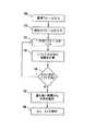
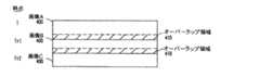
上述のように、指紋の完全で連続した画像を得るため、画像入力センサから得られた一連の画像にはステッチがかけられる。例えば、図14に示すように、時点Tにおいて、第1の画像400(画像A)が撮られる。時点T+1において、画像Aに含まれている、オーバラップする領域410を備えた第2の画像400(画像B)が撮られる。時点T+2において、画像Bに含まれている、オーバラップする領域410を備えた第3の画像(画像C)が撮られる。完全な画像を形成するため、各画像400は、順次メモリに記憶され、オーバラップする領域410は、次の画像から上書きされる。 As described above, a series of images obtained from the image input sensor is stitched to obtain a complete and continuous image of the fingerprint. For example, as shown in FIG. 14, at time T, a first image 400 (image A) is taken. At
例えば、図15には、一連の画像にステッチをかけて、1つの連続した指紋画像を形成するための典型的なプロセスが例示されている。スワイプ・インターフェースに押し付けられた指紋の一部が入力され(ブロック850)、バッファに記憶される(ブロック855)。その後続画像が入力されると(ブロック860)、最初の画像と後続画像とのオーバラップが確認される(ブロック865)。オーバラップ領域は、例えば、最初の画像と後続画像との間における移動方向及び量を表したナビゲーション情報から確認することが可能である。 For example, FIG. 15 illustrates a typical process for stitching a series of images to form one continuous fingerprint image. A portion of the fingerprint pressed against the swipe interface is entered (block 850) and stored in a buffer (block 855). When the subsequent image is input (block 860), the overlap between the first image and the subsequent image is confirmed (block 865). The overlap area can be confirmed from, for example, navigation information indicating the moving direction and the amount between the first image and the subsequent image.
最初の画像とオーバラップするその後続画像の一部は上書きされ、後続画像の残りの部分はバッファに記憶される(ブロック870)。画像は、バッファから、連続指紋画像を記憶するためのメモリ・アレイに順次出力することが可能である。このプロセスは、ユーザがスワイプ・インターフェースを横切って指を走らす間に撮られる各画像毎に繰り返される(ブロック875)。ステッチをかけられた最終的な指紋画像は、図13に関連して上述のように、ユーザの身元確認のため、指紋照合アプリケーションに供給される(ブロック880)。 The portion of the subsequent image that overlaps the first image is overwritten, and the remaining portion of the subsequent image is stored in a buffer (block 870). The images can be output sequentially from a buffer to a memory array for storing a continuous fingerprint image. This process is repeated for each image taken while the user swipes his finger across the swipe interface (block 875). The final stitched fingerprint image is provided to the fingerprint verification application for user identification, as described above in connection with FIG. 13 (block 880).
上述のように、用途に応じて、画像入力システムの他の動作モードも可能である。こうしたモードの1つがスタイラス・モードであり、スワイプ・インターフェースを横切るユーザのフィンガ・ストロークを利用して、画像入力システムの少なくとも一部を収容する電子装置において表示される文字が指示される。次に、図16A及び16Bを参照すると、典型的なフィンガ・ストロークとそれに対応する表示文字が例示されている。 As mentioned above, other modes of operation of the image input system are possible, depending on the application. One such mode is the stylus mode, in which a user's finger strokes across a swipe interface are used to indicate the characters to be displayed on an electronic device housing at least a portion of the image input system. Referring now to FIGS. 16A and 16B, exemplary finger strokes and corresponding display characters are illustrated.
図16Aに示すように、第1の基準(時間基準A)において、ユーザは、スワイプ・インターフェースの幅を横切って、x方向に指を走らせて、第1のフィンガ・ストローク90aを完了する。指を持ち上げずに、第2の時間基準(時間基準B)において、ユーザは、スワイプ・インターフェース110の全長にわたってy方向に指を走らせ、第2のフィンガ・ストローク90bを完了する。第1のフィンガ・ストロークa及び第2のフィンガ・ストロークbを組み合わせた結果として生じるナビゲーション情報は、画像入力システムによって解釈されて、英字「L」の文字520が形成され、図16Bに示すように、英字「L」が画像入力システムを導入した携帯電話500のディスプレイ510に表示される。 As shown in FIG. 16A, at a first reference (time reference A), the user runs his finger in the x-direction across the width of the swipe interface to complete the first finger stroke 90a. Without lifting the finger, at the second time reference (time reference B), the user runs the finger in the y-direction over the entire length of the
ただし、云うまでもないが、図16A及び16Bにおけるフィンガ・ストローク90a及び90b、及び、対応する英字は、例証だけを目的として示されたものであり、フィンガ・ストローク90a及び90bから生じるナビゲーション情報の特定の組み合わせは、スタイラス・アプリケーションによって決まる、任意のタイプの文字520と解釈することが可能である。さらに、云うまでもなく、任意の数の異なるフィンガ・ストローク90a及び90bを利用して、任意の電子装置500の任意のタイプのディスプレイ510上に対応する文字520を表示することが可能である。さらに、云うまでもないが、画像入力システムは、文字520を表示する電子装置内に少なくとも部分的に収容することもできるし、あるいは、それに接続することも可能である。 However, it should be understood that the finger strokes 90a and 90b and the corresponding alphabetic characters in FIGS. 16A and 16B are shown for illustrative purposes only, and that the navigation information resulting from the finger strokes 90a and 90b is not shown. The particular combination can be interpreted as any type of
次に図17を参照すると、画像入力システムがスタイラス・モードで動作している間に、ナビゲーション情報を利用して、フィンガ・ストロークによって表わされる文字を判定するための典型的なプロセスが例示されている。ユーザの指をスワイプ・インターフェースを横切って走らせると(ブロック900)、最初の時点において、基準フレームが画像入力システムによって入力され(ブロック910)、それに後続する時点において、後続の現在フレームが入力される(ブロック920)。基準フレーム及び現在フレームは、図10に関連して上述のように、相互相関されて、基準フレームと現在フレームとの間における指の移動方向及び量を表わしたナビゲーション情報が確認される(ブロック930)。画像入力システムによって一連のフレームが入力され(ブロック940)、計算されたナビゲーション情報の全てを用いて、特定文字を表わした、ユーザによって実施されるフィンガ・ストロークまたはフィンガ・ストロークの組み合わせが識別される。基準フレームは、ナビゲーション情報収集プロセスの間中同じままとすることもできるし、あるいは、新しい各現在フレーム毎に、または、現在フレームの位置に対して劣化すると、変化させることも可能である。ユーザが指を持ち上げて、スワイプ・インターフェースから離し、これがセンサの出力によって確認されると、特定文字を表わしたフィンガ・ストロークの終端であると判定される。 Referring now to FIG. 17, an exemplary process for utilizing navigation information to determine the character represented by the finger stroke while the image input system is operating in stylus mode is illustrated. I have. As the user's finger is swept across the swipe interface (block 900), at an initial point in time, a reference frame is input by the image input system (block 910), and at a subsequent time, a subsequent current frame is input. (Block 920). The reference frame and the current frame are cross-correlated, as described above in connection with FIG. 10, to determine navigation information representing the direction and amount of finger movement between the reference frame and the current frame (block 930). ). A series of frames are input by the image input system (block 940), and all of the calculated navigation information is used to identify a finger stroke or combination of finger strokes performed by the user that represents a particular character. . The reference frame can remain the same throughout the navigation information collection process, or can change with each new current frame or as it degrades with respect to the position of the current frame. When the user lifts his finger off the swipe interface and this is confirmed by the output of the sensor, it is determined to be the end of the finger stroke representing the particular character.
ナビゲーション情報を利用して、フィンガ・ストロークによって表わされる文字を識別する文字コードが判定されると(ブロック950)、その文字が、スワイプ・モジュールを組み込んだ電子装置に一体化されたディスプレイによってユーザに表示される(ブロック960)。例えば、ディスプレイは、携帯電話のLCDのように、電子装置上に配置することが可能である。もう1つの例では、ディスプレイは、もう1つの例として、ディスプレイは、スワイプ・モジュールが組み込まれたマウスに接続された、パーソナル・コンピュータに接続されたスクリーン上に配置することも可能である。 Once the navigation information has been used to determine the character code that identifies the character represented by the finger stroke (block 950), the character is provided to the user by a display integrated with the electronic device incorporating the swipe module. Displayed (block 960). For example, the display can be located on an electronic device, such as a cell phone LCD. In another example, the display may, as another example, be placed on a screen connected to a personal computer, connected to a mouse with a swipe module incorporated.
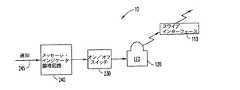
図18には、画像入力システム10がそのモードにある間、LED120がメッセージ表示灯として用いられる、画像入力システムのもう1つの動作モードである、明滅モードが示されている。例えば、画像入力システムが、音声メール・メッセージ、eメール・メッセージ、ショート・メッセージ・サービス(SMS)・メッセージ、または、他のタイプのメッセージといった、メッセージの受信が可能な電子装置に少なくとも部分的に導入されている場合、画像入力システム10のスワイプ・モジュール(図1に示す)内に含まれるLED120が、繰り返し間隔をおいて発光し、ユーザにメッセージを受信したことを知らせることが可能である。 FIG. 18 illustrates another mode of operation of the image input system, the blinking mode, in which the
図18に示すように、パーソナル・コンピュータ、ラップトップ・コンピュータ、携帯電話、または、PDAのような電子装置内に含まれるメッセージ・インジケータ論理回路240は、メッセージ受信の通告245を受信すると、LED120に接続されたオン/オフ・スイッチ230に命じて、LED120から明滅光が発せられるように、LED120を順次オン/オフさせる。オン/オフ状態は、異なるLED発光強度とすることもできるし、あるいは、オフ状態をLED120が発光しない時間期間とすることも可能である。明滅モードにある間、画像センサによって入力されるデータはない。ユーザが、画像データを必要とする別の動作モードにスイッチすると、明滅モードは、指の十分な照射を確保するために中断される。 As shown in FIG. 18, a
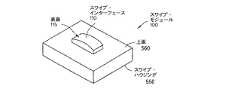
図19A及び19Bには、スワイプ・モジュール100に関するパッケージ設計の例が2つ示されている。スワイプ・モジュール100は、簡略化のため、矩形のハウジング550内に組み込まれたものとして示されている。しかし、云うまでもなく、他の形状及び設計も可能である。さらに、ハウジング550の上面560は、スイッチ・モジュール100を導入した電子装置の表面の一部を形成することが可能である。スワイプ・インターフェース110は、ハウジング550の上面560から上方に突き出して、ユーザが位置を確認したり、探ったりしやすいスワイプ表面を形成している。さらに、スワイプ・インターフェース110は、スワイプ・インターフェース110と接触する指領域を拡大するため、凸状の表面115も備えている。 19A and 19B show two examples of package design for
図19Bには、さらに、ハウジング550の上面560にある、スワイプ・インターフェースを横切る指を導いて、回転しないように走らせる機械的設計を施されたグルーブ565が例示されている。フィンガ・ナビゲーション及び指認識中に指の回転を減少させると、処理の複雑性が低下し、回転運動及び他の曲線運動を検出するための追加ナビゲーション・センサが不要になる可能性がある。 FIG. 19B further illustrates a mechanically designed
本出願において明らかにされる新規の概念は、多種多様な用途において修正及び変更を加えることが可能である。従って、特許対象の範囲は、論考された特定の典型的な教示のいずれかに限定されるべきではなく、代わりに、付属の請求項によって定義されている。 The novel concepts disclosed in the present application can be modified and varied in a wide variety of applications. Accordingly, the scope of patented subject matter should not be limited to any of the specific exemplary teachings discussed, but is instead defined by the appended claims.
なお、本発明は例として次の態様を含む。( )内の数字は添付図面の参照符号に対応する。
[1] 表面(115)に人間の指(20)の少なくとも先端部分を押し当てることが可能なセンシングエリアを備えており、前記センシングエリアに、2つ以上の区画(110a、110b、110c)が含まれていて、その少なくとも1つが選択区画(110a、110b、110c)である、フィンガ・インターフェース(110)と、
前記2つ以上の区画(110a、110b、110c)の各区画内において前記フィンガ・インターフェース(110)の前記表面(115)に押し当てられた前記人間の指(20)の先端部分を照射する光(125)を選択的に放出する、前記2つ以上の区画(110a、110b、110c)の前記各区画のためのそれぞれの光源(120a、120b、120c)と、
前記2つ以上の区画(110a、110b、110c)のそれぞれの区画内における前記人間の指(20)の先端の一部から反射した光(128)をその画像として受光して、それぞれの区画の画像に対応する画像データ(50)を生成する、前記2つ以上の区画(110a、110b、110c)の各区画のためのそれぞれの検知領域(140a、140b、140c)とを有し、
前記画像データ(50)が、前記選択区画(110a、110b、110c)のそれぞれからの光(128)を受光するようにアライメントがとられた各前記検知領域(140a、140b、140c)から得られることを特徴とする、
指紋(25)を画像化するための装置。
[2] 前記装置が、選択された動作モードで動作することと、
前記選択された動作モードは、画像入力された指紋を用いて、スクリーン上におけるカーソル位置を制御するためのフィンガ・ナビゲーション・モード、または、前記画像入力された指紋と記憶されているテンプレート指紋とを照合するための指認識モードとすることが可能であることと、
前記選択区画(110a、110b、110c)が、前記選択された動作モードに基づいて選択されることとを特徴とする、上記[1]に記載の装置。
[3] 前記各光源(120a、120b、120c)が、前記各光源に関連したオン状態とオフ状態とを有することと、
前記各選択区画(110a、110b、110c)と関連した前記各光源(120a、120b、120c)が、オン状態で動作し、前記選択区画(110a、110b、110c)のどれにも関連しない前記各光源(120a、120b、120c)は、オフ状態で動作することを特徴とする、上記[1]に記載の装置。
[4] 前記各選択区画(110a、110b、110c)に関連した前記各光源(120a、120b、120c)が、オン状態とオフ状態の間で順次動作し、前記各選択区画(110a、110b、110c)内の画像を順次入力することが可能に構成されることを特徴とする、上記[3]に記載の装置。
[5] フィンガ・ナビゲーション・モードまたは指認識モードを選択モードとすることが可能で、前記選択動作モードで動作する画像化システムであって、
センシングエリアの2つ以上の区画(110a、110b、110c)のうち、少なくとも1つの選択区画内における、人間の指(20)の先端の少なくとも一部を表わした1つ以上の区画画像に対応する画像データ(50)を入力するように接続されており、さらに、前記選択動作モードで前記画像データ(50)の処理を行うプロセッサ(210)と、
前記選択動作モードを選択し、前記選択動作モードに基づいて前記選択区画(110a、110b、110c)のそれぞれを選択するための、前記プロセッサ(210)に接続されたモード・スイッチ(220)とを備えることを特徴とする、画像入力システム。
[6] さらに、前記モード・スイッチ(220)に接続されて、前記選択動作モードに基づいて、前記区画画像のフレームレート及び露光時間を制御する画像タイミング制御回路要素(360)を具備することを特徴とする、上記[5]に記載の画像化システム。
[7] さらに、前記選択区画(110a、110b、110c)のそれぞれを照射させるように接続されたスイッチ(365)を備えることと、前記スイッチ(365)は、前記各選択区画(110a、110b、110c)内の画像を順次入力するため、前記各選択区画(110a、110b、110c)を順次照射させることができるように構成されることを特徴とする、上記[5]に記載の画像入力システム。
[8] 前記選択動作モードが、スタイラス・モードであることと、前記プロセッサ(210)が、さらに、前記センシングエリアを横切る人間の指(20)の動きに対応する1つ以上のフィンガ・ストローク(90)を確認し、前記1つ以上のフィンガ・ストローク(90)に対応する文字(520)を識別することを特徴とする、上記[5]に記載の画像入力システム。
[9] フィンガ・ナビゲーション・モードまたは指認識モードを選択モードとすることが可能で、前記選択モードで画像入力システム(10)を動作させるための方法であって、
センシングエリアの2つ以上の区画(110a、110b、110c)のうち、選択された少なくとも1つの選択区画内において照射された、人間の指(20)の先端の少なくとも一部を表わした画像データ(50)を受信することであって、それぞれの前記選択区画(110a、110b、110c)は前記選択モードに基づいて選択される、受信することと、
前記選択モードで前記画像データ(50)を処理することと、
を有することを特徴とする方法。
[10] さらに、
前記各選択区画(110a、110b、110c)内において前記センシングエリアに押し付けられた前記人間の指(20)の先端の一部を選択的に照射することと、
前記各選択区画(110a、110b、110c)内における前記人間の指(20)の先端の一部から反射される光(128)をその区画画像として受光することと、
前記区画画像に応答して、前記画像データ(50)を生成することと、
を有することを特徴とする上記[9]に記載の方法。The present invention includes the following aspects as examples. The numbers in parentheses correspond to the reference numerals in the attached drawings.
[1] A sensing area capable of pressing at least a tip portion of a human finger (20) against a surface (115) is provided, and two or more sections (110a, 110b, 110c) are provided in the sensing area. A finger interface (110), of which at least one is a selection section (110a, 110b, 110c);
Light illuminating the tip of the human finger (20) pressed against the surface (115) of the finger interface (110) in each of the two or more compartments (110a, 110b, 110c). A respective light source (120a, 120b, 120c) for each of said two or more sections (110a, 110b, 110c), selectively emitting (125);
The light (128) reflected from a part of the tip of the human finger (20) in each of the two or more sections (110a, 110b, 110c) is received as an image, and the A respective sensing area (140a, 140b, 140c) for each of said two or more sections (110a, 110b, 110c) for generating image data (50) corresponding to the image;
The image data (50) is obtained from each of the sensing areas (140a, 140b, 140c) aligned to receive light (128) from each of the selected sections (110a, 110b, 110c). Characterized by the fact that
A device for imaging a fingerprint (25).
[2] the device operates in a selected operation mode;
The selected operation mode includes a finger navigation mode for controlling a cursor position on a screen using an image-input fingerprint, or a finger-navigation mode for controlling the cursor position on the screen, or the image-input fingerprint and a stored template fingerprint. It is possible to set a finger recognition mode for collation,
The apparatus according to [1], wherein the selected section (110a, 110b, 110c) is selected based on the selected operation mode.
[3] each of the light sources (120a, 120b, 120c) has an on state and an off state associated with each of the light sources;
Each of the light sources (120a, 120b, 120c) associated with each of the selected sections (110a, 110b, 110c) operates in an on state, and each of the light sources (120a, 110b, 110c) not associated with any of the selected sections (110a, 110b, 110c). The device according to [1], wherein the light sources (120a, 120b, 120c) operate in an off state.
[4] The light sources (120a, 120b, 120c) associated with the selected sections (110a, 110b, 110c) sequentially operate between an on state and an off state, and the selected sections (110a, 110b, The apparatus according to [3], wherein the apparatus is configured to be capable of sequentially inputting the images in 110c).
[5] An imaging system which can be set to a finger navigation mode or a finger recognition mode as a selection mode, and operates in the selection operation mode.
Among the two or more sections (110a, 110b, 110c) of the sensing area, at least one selected section corresponds to one or more section images representing at least a part of the tip of the human finger (20). A processor (210) connected to input image data (50), and further processing the image data (50) in the selected operation mode;
A mode switch (220) connected to the processor (210) for selecting the selected operation mode and selecting each of the selected sections (110a, 110b, 110c) based on the selected operation mode. An image input system, comprising:
[6] An image timing control circuit element (360) connected to the mode switch (220) and controlling a frame rate and an exposure time of the divided image based on the selected operation mode. The imaging system according to the above [5], which is characterized in that:
[7] Further, a switch (365) connected to irradiate each of the selected sections (110a, 110b, 110c) is provided, and the switch (365) is connected to each of the selected sections (110a, 110b, The image input system according to the above [5], wherein each of the selected sections (110a, 110b, 110c) can be sequentially irradiated so as to sequentially input the image in the
[8] The selection operation mode is a stylus mode, and the processor (210) further includes one or more finger strokes (20) corresponding to movement of a human finger (20) across the sensing area. 90), and identifies a character (520) corresponding to the one or more finger strokes (90).
[9] A method for operating the image input system (10) in the finger navigation mode or the finger recognition mode in the selection mode.
Image data representing at least a part of the tip of the human finger (20) irradiated in at least one selected section selected from the two or more sections (110a, 110b, 110c) of the sensing area (110) 50), wherein each of the selection sections (110a, 110b, 110c) is selected based on the selection mode, receiving;
Processing the image data (50) in the selection mode;
A method comprising:
[10] Furthermore,
Selectively irradiating a part of the tip of the human finger (20) pressed against the sensing area in each of the selection sections (110a, 110b, 110c);
Receiving light (128) reflected from a part of the tip of the human finger (20) in each of the selected sections (110a, 110b, 110c) as the section image;
Generating the image data (50) in response to the segment image;
The method according to the above [9], comprising:
10 画像入力システム
20 指
25 指紋
50 画像データ
90 フィンガ・ストローク
100 スワイプ・モジュール
110 スワイプ・インターフェース(フィンガ・インターフェース)
110a、110b、110c スワイプ・インターフェースの区画
115 スワイプ・インターフェースの表面(上面)
120a、120b、120c 光源
140 センサ
140a、140b、140c 検知領域(受光領域)
210 プロセッサ
220 モード・スイッチ
360 画像タイミング制御回路要素
365 オン/オフ・スイッチ
110a, 110b, 110c
120a, 120b,
210
Claims (1)
Translated fromJapanese前記2つ以上の区画(110a、110b、110c)の各区画内において前記フィンガ・インターフェース(110)の前記表面(115)に押し当てられた前記人間の指(20)の先端部分を照射する光(125)を選択的に放出する、前記2つ以上の区画(110a、110b、110c)の前記各区画のためのそれぞれの光源(120a、120b、120c)と、
前記2つ以上の区画(110a、110b、110c)のそれぞれの区画内における前記人間の指(20)の先端の一部から反射した光(128)をその画像として受光して、それぞれの区画の画像に対応する画像データ(50)を生成する、前記2つ以上の区画(110a、110b、110c)の各区画のためのそれぞれの検知領域(140a、140b、140c)とを有し、
前記画像データ(50)が、前記選択区画(110a、110b、110c)のそれぞれからの光(128)を受光するようにアライメントがとられた各前記検知領域(140a、140b、140c)から得られることを特徴とする、
指紋(25)を画像化するための装置。A sensing area capable of pressing at least a tip portion of a human finger (20) on the surface (115) is provided, and the sensing area includes two or more sections (110a, 110b, 110c). A finger interface (110), at least one of which is a selection section (110a, 110b, 110c);
Light illuminating the tip of the human finger (20) pressed against the surface (115) of the finger interface (110) in each of the two or more compartments (110a, 110b, 110c). A respective light source (120a, 120b, 120c) for each of said two or more sections (110a, 110b, 110c), selectively emitting (125);
The light (128) reflected from a part of the tip of the human finger (20) in each of the two or more sections (110a, 110b, 110c) is received as an image, and the A respective sensing area (140a, 140b, 140c) for each of said two or more sections (110a, 110b, 110c) for generating image data (50) corresponding to the image;
The image data (50) is obtained from each of the sensing areas (140a, 140b, 140c) aligned to receive light (128) from each of the selected sections (110a, 110b, 110c). Characterized by the fact that
A device for imaging a fingerprint (25).
Applications Claiming Priority (1)
| Application Number | Priority Date | Filing Date | Title |
|---|---|---|---|
| US10/418,968US7158659B2 (en) | 2003-04-18 | 2003-04-18 | System and method for multiplexing illumination in combined finger recognition and finger navigation module |
Publications (2)
| Publication Number | Publication Date |
|---|---|
| JP2004318891Atrue JP2004318891A (en) | 2004-11-11 |
| JP2004318891A5 JP2004318891A5 (en) | 2007-06-07 |
Family
ID=32094165
Family Applications (1)
| Application Number | Title | Priority Date | Filing Date |
|---|---|---|---|
| JP2004121381AWithdrawnJP2004318891A (en) | 2003-04-18 | 2004-04-16 | System and method for multiplexing reflections in a combined finger recognition and finger navigation module |
Country Status (3)
| Country | Link |
|---|---|
| US (1) | US7158659B2 (en) |
| JP (1) | JP2004318891A (en) |
| GB (1) | GB2400715B (en) |
Families Citing this family (124)
| Publication number | Priority date | Publication date | Assignee | Title |
|---|---|---|---|---|
| US20050018884A1 (en)* | 2003-07-22 | 2005-01-27 | Lg Electronics Inc. | Fingerprint sensor, fabrication method thereof and fingerprint sensing system |
| US8447077B2 (en)* | 2006-09-11 | 2013-05-21 | Validity Sensors, Inc. | Method and apparatus for fingerprint motion tracking using an in-line array |
| US8077935B2 (en) | 2004-04-23 | 2011-12-13 | Validity Sensors, Inc. | Methods and apparatus for acquiring a swiped fingerprint image |
| US8165355B2 (en) | 2006-09-11 | 2012-04-24 | Validity Sensors, Inc. | Method and apparatus for fingerprint motion tracking using an in-line array for use in navigation applications |
| US8131026B2 (en) | 2004-04-16 | 2012-03-06 | Validity Sensors, Inc. | Method and apparatus for fingerprint image reconstruction |
| US8175345B2 (en) | 2004-04-16 | 2012-05-08 | Validity Sensors, Inc. | Unitized ergonomic two-dimensional fingerprint motion tracking device and method |
| US8229184B2 (en) | 2004-04-16 | 2012-07-24 | Validity Sensors, Inc. | Method and algorithm for accurate finger motion tracking |
| US8358815B2 (en) | 2004-04-16 | 2013-01-22 | Validity Sensors, Inc. | Method and apparatus for two-dimensional finger motion tracking and control |
| USD514570S1 (en) | 2004-06-24 | 2006-02-07 | Microsoft Corporation | Region of a fingerprint scanning device with an illuminated ring |
| US7521719B2 (en)* | 2004-08-13 | 2009-04-21 | Paul Steven Schranz | Light emitting and image sensing device and apparatus |
| EP1805581A1 (en)* | 2004-08-20 | 2007-07-11 | Crucialtec Co., Ltd. | Ultra thin optical joystick and personal portable device having ultra thin optical joystick |
| DE602005022900D1 (en)* | 2004-10-04 | 2010-09-23 | Validity Sensors Inc | FINGERPRINTER CONSTRUCTIONS WITH ONE SUBSTRATE |
| TW200612353A (en)* | 2004-10-15 | 2006-04-16 | Lite On Semiconductor Corp | Optical sensing module, optical sensing, image-capturing structure and optical print sensing method of handheld communication system |
| TWM267551U (en)* | 2004-12-21 | 2005-06-11 | Lite On Semiconductor Corp | Contact image sensing module with fingerprint scanning function |
| US7791434B2 (en)* | 2004-12-22 | 2010-09-07 | Avago Technologies Wireless Ip (Singapore) Pte. Ltd. | Acoustic resonator performance enhancement using selective metal etch and having a trench in the piezoelectric |
| TWM268675U (en)* | 2004-12-24 | 2005-06-21 | Lite On Semiconductor Corp | Touch type image sensing module with motion detection function |
| TWM268676U (en)* | 2004-12-28 | 2005-06-21 | Lite On Semiconductor Corp | Fingerprint scan device and electric equipment with fingerprint scan function |
| US20070040108A1 (en)* | 2005-08-16 | 2007-02-22 | Wenstrand John S | Optical sensor light switch |
| US20070057929A1 (en)* | 2005-09-13 | 2007-03-15 | Tong Xie | Navigation device with a contoured region that provides tactile feedback |
| KR100701520B1 (en)* | 2006-06-26 | 2007-03-29 | 삼성전자주식회사 | User Interface Method by Touching Keypad and Its Mobile Terminal |
| JP4864632B2 (en)* | 2006-10-12 | 2012-02-01 | 株式会社リコー | Image input device, image input method, personal authentication device, and electronic device |
| GB2446837A (en)* | 2006-10-18 | 2008-08-27 | Unilink Software | Handheld fingerprint analysis unit |
| KR100790118B1 (en)* | 2006-10-25 | 2008-01-02 | 삼성전자주식회사 | Key pad |
| US9411431B2 (en)* | 2006-12-29 | 2016-08-09 | Marvell World Trade Ltd. | Tracking a position in relation to a surface |
| US8632266B1 (en) | 2007-01-03 | 2014-01-21 | Marvell International Ltd. | Printer for a mobile device |
| US8077343B1 (en) | 2007-01-03 | 2011-12-13 | Marvell International Ltd. | Determining end of print job in handheld image translation device |
| US7949370B1 (en) | 2007-01-03 | 2011-05-24 | Marvell International Ltd. | Scanner for a mobile device |
| US8472066B1 (en) | 2007-01-11 | 2013-06-25 | Marvell International Ltd. | Usage maps in image deposition devices |
| US8396654B1 (en)* | 2007-01-18 | 2013-03-12 | Marvell International Ltd. | Sensor positioning in handheld image translation device |
| US8223384B1 (en) | 2007-02-23 | 2012-07-17 | Marvell International Ltd. | Defining a print image in memory for handheld image translation devices |
| EP2114688A1 (en)* | 2007-02-23 | 2009-11-11 | Marvell World Trade Ltd | Determining positioning of a handheld image translation device |
| US8351062B2 (en)* | 2007-02-26 | 2013-01-08 | Marvell World Trade Ltd. | Bit selection from print image in memory of handheld image translation device |
| WO2008109557A1 (en)* | 2007-03-02 | 2008-09-12 | Marvell World Trade Ltd. | Dynamic image dithering |
| US9294649B2 (en)* | 2007-03-02 | 2016-03-22 | Marvell World Trade Ltd. | Position correction in handheld image translation device |
| US9180686B1 (en)* | 2007-04-05 | 2015-11-10 | Marvell International Ltd. | Image translation device providing navigational data feedback to communication device |
| US8325154B2 (en)* | 2007-04-20 | 2012-12-04 | Pixart Imaging Incorporation | Optical touch control apparatus and method thereof |
| US8107212B2 (en) | 2007-04-30 | 2012-01-31 | Validity Sensors, Inc. | Apparatus and method for protecting fingerprint sensing circuitry from electrostatic discharge |
| US8290150B2 (en) | 2007-05-11 | 2012-10-16 | Validity Sensors, Inc. | Method and system for electronically securing an electronic device using physically unclonable functions |
| US9555645B1 (en) | 2007-08-07 | 2017-01-31 | Marvell International Ltd. | Controlling a plurality of nozzles of a handheld printer |
| US20090102793A1 (en)* | 2007-10-22 | 2009-04-23 | Microsoft Corporation | Optical mouse |
| US8189881B1 (en)* | 2007-11-27 | 2012-05-29 | Texas Instruments Incorporated | Fingerprint sensor using beams of light and methods of manufacture and use |
| US8204281B2 (en) | 2007-12-14 | 2012-06-19 | Validity Sensors, Inc. | System and method to remove artifacts from fingerprint sensor scans |
| US8276816B2 (en) | 2007-12-14 | 2012-10-02 | Validity Sensors, Inc. | Smart card system with ergonomic fingerprint sensor and method of using |
| US8847888B2 (en)* | 2007-12-18 | 2014-09-30 | Microsoft Corporation | Optical mouse with limited wavelength optics |
| US20090160772A1 (en)* | 2007-12-20 | 2009-06-25 | Microsoft Corporation | Diffuse optics in an optical mouse |
| US20090160773A1 (en)* | 2007-12-20 | 2009-06-25 | Microsoft Corporation | Optical mouse |
| US8165428B2 (en)* | 2008-03-31 | 2012-04-24 | Intel Corporation | Optical imaging based computer pointing |
| US8005276B2 (en) | 2008-04-04 | 2011-08-23 | Validity Sensors, Inc. | Apparatus and method for reducing parasitic capacitive coupling and noise in fingerprint sensing circuits |
| US8116540B2 (en) | 2008-04-04 | 2012-02-14 | Validity Sensors, Inc. | Apparatus and method for reducing noise in fingerprint sensing circuits |
| TWI367435B (en)* | 2008-04-08 | 2012-07-01 | Pixart Imaging Inc | Optical scrolling module and optical control module |
| US9285459B2 (en) | 2008-05-09 | 2016-03-15 | Analog Devices, Inc. | Method of locating an object in 3D |
| US8698594B2 (en) | 2008-07-22 | 2014-04-15 | Synaptics Incorporated | System, device and method for securing a user device component by authenticating the user of a biometric sensor by performance of a replication of a portion of an authentication process performed at a remote computing device |
| US8391568B2 (en) | 2008-11-10 | 2013-03-05 | Validity Sensors, Inc. | System and method for improved scanning of fingerprint edges |
| US9746544B2 (en) | 2008-12-03 | 2017-08-29 | Analog Devices, Inc. | Position measurement systems using position sensitive detectors |
| US8600122B2 (en) | 2009-01-15 | 2013-12-03 | Validity Sensors, Inc. | Apparatus and method for culling substantially redundant data in fingerprint sensing circuits |
| US8278946B2 (en) | 2009-01-15 | 2012-10-02 | Validity Sensors, Inc. | Apparatus and method for detecting finger activity on a fingerprint sensor |
| DE102009005092A1 (en)* | 2009-01-19 | 2010-09-02 | Fraunhofer-Gesellschaft zur Förderung der angewandten Forschung e.V. | Device for optical navigation and its use |
| US8797298B2 (en)* | 2009-01-23 | 2014-08-05 | Avago Technologies General Ip (Singapore) Pte. Ltd. | Optical fingerprint navigation device with light guide film |
| US8374407B2 (en) | 2009-01-28 | 2013-02-12 | Validity Sensors, Inc. | Live finger detection |
| KR101549557B1 (en)* | 2009-03-10 | 2015-09-03 | 엘지전자 주식회사 | Mobile terminal and control method thereof |
| US20100237991A1 (en)* | 2009-03-17 | 2010-09-23 | Prabhu Krishnanand | Biometric scanning arrangement and methods thereof |
| GB2470554A (en)* | 2009-05-26 | 2010-12-01 | St Microelectronics Ltd | Optical navigation device with housing and optical transmission element to a mousing surface |
| GB2470553A (en)* | 2009-05-26 | 2010-12-01 | St Microelectronics Ltd | Optical computer input with single frustrated total internal reflection mousing surface |
| CN102802509B (en) | 2009-05-27 | 2017-06-09 | 美国亚德诺半导体公司 | Multiuse optical sensor |
| US8248185B2 (en)* | 2009-06-24 | 2012-08-21 | Avago Technologies Wireless Ip (Singapore) Pte. Ltd. | Acoustic resonator structure comprising a bridge |
| US8902023B2 (en)* | 2009-06-24 | 2014-12-02 | Avago Technologies General Ip (Singapore) Pte. Ltd. | Acoustic resonator structure having an electrode with a cantilevered portion |
| US9336428B2 (en) | 2009-10-30 | 2016-05-10 | Synaptics Incorporated | Integrated fingerprint sensor and display |
| US9274553B2 (en) | 2009-10-30 | 2016-03-01 | Synaptics Incorporated | Fingerprint sensor and integratable electronic display |
| US9400911B2 (en) | 2009-10-30 | 2016-07-26 | Synaptics Incorporated | Fingerprint sensor and integratable electronic display |
| US8866347B2 (en) | 2010-01-15 | 2014-10-21 | Idex Asa | Biometric image sensing |
| US8421890B2 (en) | 2010-01-15 | 2013-04-16 | Picofield Technologies, Inc. | Electronic imager using an impedance sensor grid array and method of making |
| US8791792B2 (en) | 2010-01-15 | 2014-07-29 | Idex Asa | Electronic imager using an impedance sensor grid array mounted on or about a switch and method of making |
| TW201126385A (en)* | 2010-01-25 | 2011-08-01 | Maxemil Photonics Corp | Optical position indication input apparatus |
| US9666635B2 (en) | 2010-02-19 | 2017-05-30 | Synaptics Incorporated | Fingerprint sensing circuit |
| US8716613B2 (en) | 2010-03-02 | 2014-05-06 | Synaptics Incoporated | Apparatus and method for electrostatic discharge protection |
| US20110267277A1 (en)* | 2010-05-03 | 2011-11-03 | Crestron Electronics, Inc. | Thumb Operated Tablet Remote Control |
| US9001040B2 (en) | 2010-06-02 | 2015-04-07 | Synaptics Incorporated | Integrated fingerprint sensor and navigation device |
| DE102010027499A1 (en)* | 2010-07-16 | 2012-01-19 | Mechaless Systems Gmbh | Optical control, in particular push-button or switch |
| US8331096B2 (en) | 2010-08-20 | 2012-12-11 | Validity Sensors, Inc. | Fingerprint acquisition expansion card apparatus |
| GB2484077A (en)* | 2010-09-28 | 2012-04-04 | St Microelectronics Res & Dev | An Optical Device Functioning as Both a Fingerprint Detector and a Navigation Input |
| US20120121143A1 (en)* | 2010-11-11 | 2012-05-17 | Hung-Te Lee | Fingerprint imaging system |
| US8816963B2 (en) | 2010-12-13 | 2014-08-26 | Sae Magnetics (H.K.) Ltd. | Optical navigation module and mobile electronic appliance using optical navigation module |
| US8594393B2 (en) | 2011-01-26 | 2013-11-26 | Validity Sensors | System for and method of image reconstruction with dual line scanner using line counts |
| US8538097B2 (en) | 2011-01-26 | 2013-09-17 | Validity Sensors, Inc. | User input utilizing dual line scanner apparatus and method |
| US8962443B2 (en) | 2011-01-31 | 2015-02-24 | Avago Technologies General Ip (Singapore) Pte. Ltd. | Semiconductor device having an airbridge and method of fabricating the same |
| US9104268B2 (en) | 2011-02-03 | 2015-08-11 | Avago Technologies General Ip (Singapore) Pte. Ltd. | Compact optical finger navigation system with illumination via redirection surface holes |
| US9154112B2 (en) | 2011-02-28 | 2015-10-06 | Avago Technologies General Ip (Singapore) Pte. Ltd. | Coupled resonator filter comprising a bridge |
| US9048812B2 (en) | 2011-02-28 | 2015-06-02 | Avago Technologies General Ip (Singapore) Pte. Ltd. | Bulk acoustic wave resonator comprising bridge formed within piezoelectric layer |
| US9148117B2 (en) | 2011-02-28 | 2015-09-29 | Avago Technologies General Ip (Singapore) Pte. Ltd. | Coupled resonator filter comprising a bridge and frame elements |
| US9203374B2 (en) | 2011-02-28 | 2015-12-01 | Avago Technologies General Ip (Singapore) Pte. Ltd. | Film bulk acoustic resonator comprising a bridge |
| US9083302B2 (en) | 2011-02-28 | 2015-07-14 | Avago Technologies General Ip (Singapore) Pte. Ltd. | Stacked bulk acoustic resonator comprising a bridge and an acoustic reflector along a perimeter of the resonator |
| US9136818B2 (en) | 2011-02-28 | 2015-09-15 | Avago Technologies General Ip (Singapore) Pte. Ltd. | Stacked acoustic resonator comprising a bridge |
| US9406580B2 (en) | 2011-03-16 | 2016-08-02 | Synaptics Incorporated | Packaging for fingerprint sensors and methods of manufacture |
| US8575820B2 (en) | 2011-03-29 | 2013-11-05 | Avago Technologies General Ip (Singapore) Pte. Ltd. | Stacked bulk acoustic resonator |
| US8704153B2 (en) | 2011-07-07 | 2014-04-22 | Sae Magnetics (H.K.) Ltd. | Side mounting optical navigation module |
| RU2475185C1 (en)* | 2011-08-10 | 2013-02-20 | Общество С Ограниченной Ответственностью "Абилма" | Papillary picture recording system |
| US10043052B2 (en) | 2011-10-27 | 2018-08-07 | Synaptics Incorporated | Electronic device packages and methods |
| US9702690B2 (en) | 2011-12-19 | 2017-07-11 | Analog Devices, Inc. | Lens-less optical position measuring sensor |
| US9195877B2 (en) | 2011-12-23 | 2015-11-24 | Synaptics Incorporated | Methods and devices for capacitive image sensing |
| US9785299B2 (en) | 2012-01-03 | 2017-10-10 | Synaptics Incorporated | Structures and manufacturing methods for glass covered electronic devices |
| TWI579751B (en)* | 2012-03-16 | 2017-04-21 | 原相科技股份有限公司 | Optical touch apparatus capable of detecting displacement and optical touch method thereof |
| CN103324353B (en)* | 2012-03-23 | 2016-08-17 | 原相科技股份有限公司 | Can optical touch control device and optical touch control method for detecting displacement |
| US9268991B2 (en) | 2012-03-27 | 2016-02-23 | Synaptics Incorporated | Method of and system for enrolling and matching biometric data |
| US9251329B2 (en) | 2012-03-27 | 2016-02-02 | Synaptics Incorporated | Button depress wakeup and wakeup strategy |
| US9137438B2 (en) | 2012-03-27 | 2015-09-15 | Synaptics Incorporated | Biometric object sensor and method |
| US9600709B2 (en) | 2012-03-28 | 2017-03-21 | Synaptics Incorporated | Methods and systems for enrolling biometric data |
| US9152838B2 (en) | 2012-03-29 | 2015-10-06 | Synaptics Incorporated | Fingerprint sensor packagings and methods |
| US20130279769A1 (en) | 2012-04-10 | 2013-10-24 | Picofield Technologies Inc. | Biometric Sensing |
| US9208371B2 (en) | 2012-09-28 | 2015-12-08 | Synaptics Incorporated | Low power navigation devices, systems and methods |
| US9665762B2 (en) | 2013-01-11 | 2017-05-30 | Synaptics Incorporated | Tiered wakeup strategy |
| US9245165B2 (en) | 2013-03-15 | 2016-01-26 | Google Technology Holdings LLC | Auxiliary functionality control and fingerprint authentication based on a same user input |
| US20140270413A1 (en)* | 2013-03-15 | 2014-09-18 | Motorola Mobility Llc | Auxiliary device functionality augmented with fingerprint sensor |
| TWI554953B (en)* | 2015-10-30 | 2016-10-21 | 培新科技股份有限公司 | Fingerprint image capturing device and fingerprint image capturing module thereof |
| US10176355B2 (en) | 2015-12-03 | 2019-01-08 | Synaptics Incorporated | Optical sensor for integration in a display |
| US10169630B2 (en) | 2015-12-03 | 2019-01-01 | Synaptics Incorporated | Optical sensor for integration over a display backplane |
| US9934418B2 (en)* | 2015-12-03 | 2018-04-03 | Synaptics Incorporated | Display integrated optical fingerprint sensor with angle limiting reflector |
| US10713458B2 (en) | 2016-05-23 | 2020-07-14 | InSyte Systems | Integrated light emitting display and sensors for detecting biologic characteristics |
| US10931859B2 (en) | 2016-05-23 | 2021-02-23 | InSyte Systems | Light emitter and sensors for detecting biologic characteristics |
| US10380395B2 (en)* | 2016-09-30 | 2019-08-13 | Synaptics Incorporated | Optical sensor with angled reflectors |
| US10503951B2 (en)* | 2018-02-28 | 2019-12-10 | Superc-Touch Corporation | Rapid identification method for fingerprint |
| CN109690566B (en)* | 2018-12-04 | 2023-05-12 | 深圳市汇顶科技股份有限公司 | An optical fingerprint recognition module and electronic device |
| CN109583420B (en)* | 2018-12-14 | 2021-02-05 | 京东方科技集团股份有限公司 | Driving method and equipment of fingerprint identification device |
| US11674797B2 (en) | 2020-03-22 | 2023-06-13 | Analog Devices, Inc. | Self-aligned light angle sensor using thin metal silicide anodes |
| CN113536962A (en)* | 2021-06-24 | 2021-10-22 | 武汉天马微电子有限公司 | Display device and fingerprint identification method |
Family Cites Families (46)
| Publication number | Priority date | Publication date | Assignee | Title |
|---|---|---|---|---|
| JPS5923390B2 (en)* | 1978-10-09 | 1984-06-01 | 工業技術院長 | Method for measuring the speed of a moving object using speckles |
| US4521772A (en)* | 1981-08-28 | 1985-06-04 | Xerox Corporation | Cursor control device |
| US4631400A (en)* | 1984-01-20 | 1986-12-23 | California Institute Of Technology | Correlating optical motion detector |
| USD288930S (en)* | 1984-06-27 | 1987-03-24 | Hewlett-Packard Company | Computer mouse |
| US4794384A (en)* | 1984-09-27 | 1988-12-27 | Xerox Corporation | Optical translator device |
| US4799049A (en)* | 1985-01-25 | 1989-01-17 | Avila Harold C | Image position control |
| US4751505A (en)* | 1986-06-23 | 1988-06-14 | Xerox Corporation | Optical mouse |
| US4804949A (en)* | 1987-03-20 | 1989-02-14 | Everex Ti Corporation | Hand-held optical scanner and computer mouse |
| US4978860A (en)* | 1988-09-21 | 1990-12-18 | Hewlett-Packard Company | Optical system for a large depth-of-field bar code scanner |
| US5089712A (en)* | 1989-06-08 | 1992-02-18 | Hewlett-Packard Company | Sheet advancement control system detecting fiber pattern of sheet |
| USD314194S (en)* | 1989-12-11 | 1991-01-29 | Hewlett-Packard Company | Computer mouse |
| US5355146A (en)* | 1990-03-05 | 1994-10-11 | Bmc Micro-Industries Ltd. | Multi-directional hand scanner and mouse |
| US5149980A (en)* | 1991-11-01 | 1992-09-22 | Hewlett-Packard Company | Substrate advance measurement system using cross-correlation of light sensor array signals |
| JP3234848B2 (en)* | 1994-12-13 | 2001-12-04 | アルプス電気株式会社 | Relative angle detector |
| US5578813A (en)* | 1995-03-02 | 1996-11-26 | Allen; Ross R. | Freehand image scanning device which compensates for non-linear movement |
| US5786804A (en)* | 1995-10-06 | 1998-07-28 | Hewlett-Packard Company | Method and system for tracking attitude |
| CA2189700C (en)* | 1995-12-27 | 2000-06-20 | Alexander George Dickinson | Combination mouse and area imager |
| US5769384A (en)* | 1996-01-25 | 1998-06-23 | Hewlett-Packard Company | Low differential light level photoreceptors |
| US5729008A (en)* | 1996-01-25 | 1998-03-17 | Hewlett-Packard Company | Method and device for tracking relative movement by correlating signals from an array of photoelements |
| US5933515A (en)* | 1996-07-25 | 1999-08-03 | California Institute Of Technology | User identification through sequential input of fingerprints |
| DE69737495T2 (en)* | 1997-04-14 | 2008-01-10 | Hewlett-Packard Development Company, L.P., Houston | Method and apparatus for image scanning |
| US6049621A (en)* | 1997-08-22 | 2000-04-11 | International Business Machines Corporation | Determining a point correspondence between two points in two respective (fingerprint) images |
| US6289112B1 (en)* | 1997-08-22 | 2001-09-11 | International Business Machines Corporation | System and method for determining block direction in fingerprint images |
| US6185318B1 (en)* | 1997-08-22 | 2001-02-06 | International Business Machines Corporation | System and method for matching (fingerprint) images an aligned string-based representation |
| US6263091B1 (en)* | 1997-08-22 | 2001-07-17 | International Business Machines Corporation | System and method for identifying foreground and background portions of digitized images |
| US6314197B1 (en)* | 1997-08-22 | 2001-11-06 | International Business Machines Corporation | Determining an alignment estimation between two (fingerprint) images |
| EP0905646A1 (en)* | 1997-09-30 | 1999-03-31 | Compaq Computer Corporation | Pointing and fingerprint identifier mechanism for a computer system |
| US6172354B1 (en)* | 1998-01-28 | 2001-01-09 | Microsoft Corporation | Operator input device |
| US6104020A (en)* | 1998-02-17 | 2000-08-15 | Agilent Technologies | Electronic shutter for a low differential light level photo-receiver cell |
| US6233368B1 (en)* | 1998-03-18 | 2001-05-15 | Agilent Technologies, Inc. | CMOS digital optical navigation chip |
| US6002124A (en)* | 1998-03-20 | 1999-12-14 | Hewlett-Packard Company | Portable image scanner with optical position sensors |
| US6047091A (en)* | 1998-04-01 | 2000-04-04 | Hewlett-Packard Company | Low latency architecture for spatial filtration |
| US6049338A (en)* | 1998-04-01 | 2000-04-11 | Hewlett-Packard Company | Spatial filter for surface texture navigation |
| US6151015A (en)* | 1998-04-27 | 2000-11-21 | Agilent Technologies | Pen like computer pointing device |
| US5994710A (en)* | 1998-04-30 | 1999-11-30 | Hewlett-Packard Company | Scanning mouse for a computer system |
| US6057540A (en)* | 1998-04-30 | 2000-05-02 | Hewlett-Packard Co | Mouseless optical and position translation type screen pointer control for a computer system |
| US6195475B1 (en)* | 1998-09-15 | 2001-02-27 | Hewlett-Packard Company | Navigation system for handheld scanner |
| US6265706B1 (en)* | 1999-07-12 | 2001-07-24 | Hewlett-Packard Company | Edge to edge image sensor and navigator for portable scanner |
| US6303921B1 (en)* | 1999-11-23 | 2001-10-16 | Hewlett-Packard Company | Method and system for capturing large format documents using a portable hand-held scanner |
| US6898301B2 (en)* | 2000-07-10 | 2005-05-24 | Casio Computer Co., Ltd. | Authentication system based on fingerprint and electronic device employed for the system |
| US7289649B1 (en) | 2000-08-10 | 2007-10-30 | Avago Technologies Ecbu Ip (Singapore) Pte. Ltd. | Fingerprint imager |
| WO2002025459A1 (en)* | 2000-09-20 | 2002-03-28 | Sony Corporation | Distribution system and distribution method |
| JP4022090B2 (en)* | 2002-03-27 | 2007-12-12 | 富士通株式会社 | Finger movement detection method and detection apparatus |
| US20040125993A1 (en)* | 2002-12-30 | 2004-07-01 | Yilin Zhao | Fingerprint security systems in handheld electronic devices and methods therefor |
| US7786983B2 (en)* | 2003-04-08 | 2010-08-31 | Poa Sana Liquidating Trust | Apparatus and method for a data input device using a light lamina screen |
| US7280677B2 (en)* | 2003-10-10 | 2007-10-09 | Authentec, Inc. | Electronic device including fingerprint sensor and display having selectable menu items and associated methods |
- 2003
- 2003-04-18USUS10/418,968patent/US7158659B2/ennot_activeExpired - Lifetime
- 2004
- 2004-03-02GBGB0404680Apatent/GB2400715B/ennot_activeExpired - Fee Related
- 2004-04-16JPJP2004121381Apatent/JP2004318891A/ennot_activeWithdrawn
Also Published As
| Publication number | Publication date |
|---|---|
| US7158659B2 (en) | 2007-01-02 |
| US20040208346A1 (en) | 2004-10-21 |
| GB0404680D0 (en) | 2004-04-07 |
| GB2400715B (en) | 2006-08-30 |
| GB2400715A (en) | 2004-10-20 |
Similar Documents
| Publication | Publication Date | Title |
|---|---|---|
| JP2004318891A (en) | System and method for multiplexing reflections in a combined finger recognition and finger navigation module | |
| JP2004318892A (en) | Spatio-temporal multiplexing system and method for finger image input application | |
| JP2004318890A (en) | Image input system and apparatus for combining finger recognition and finger navigation | |
| US7313255B2 (en) | System and method for optically detecting a click event | |
| US6151015A (en) | Pen like computer pointing device | |
| EP0749612B1 (en) | An electro-optic palm scanner system employing a non-planar platen | |
| US6993165B2 (en) | System having a rotating optical system and a non-planar prism that are used to obtain print and other hand characteristic information | |
| EP3319009B1 (en) | Living body recognition apparatus, living body recognition method and living body authentication system | |
| US20040041798A1 (en) | Pointing device and scanner, robot, mobile communication device and electronic dictionary using the same | |
| JP2009505305A (en) | Free space pointing and handwriting | |
| EP2256600A2 (en) | Optimal use of F-TIR issues in finger mouse | |
| US20070109273A1 (en) | Method of capturing user control inputs | |
| US20050105078A1 (en) | Palm print scanner and methods | |
| US20230386249A1 (en) | Presentation attack detection | |
| US8917235B2 (en) | User control input device | |
| KR100843590B1 (en) | Optical pointing device and portable terminal having same | |
| KR100615554B1 (en) | Tactile information input system and device for micro information equipment | |
| KR100864289B1 (en) | Optical pointing device and portable terminal having same | |
| US7180643B2 (en) | Live print scanner with holographic imaging a different magnifications | |
| WO1999060467A1 (en) | Device and method for recording hand-written information | |
| US9116559B2 (en) | Optics for pencil optical input computer peripheral controller | |
| JP2000339397A (en) | Two-dimensional information reader | |
| JPH04120671A (en) | fingerprint input device |
Legal Events
| Date | Code | Title | Description |
|---|---|---|---|
| A711 | Notification of change in applicant | Free format text:JAPANESE INTERMEDIATE CODE: A711 Effective date:20070326 | |
| A521 | Request for written amendment filed | Free format text:JAPANESE INTERMEDIATE CODE: A523 Effective date:20070328 | |
| A621 | Written request for application examination | Free format text:JAPANESE INTERMEDIATE CODE: A621 Effective date:20070328 | |
| RD03 | Notification of appointment of power of attorney | Free format text:JAPANESE INTERMEDIATE CODE: A7423 Effective date:20070411 | |
| A521 | Request for written amendment filed | Free format text:JAPANESE INTERMEDIATE CODE: A523 Effective date:20070413 | |
| A761 | Written withdrawal of application | Free format text:JAPANESE INTERMEDIATE CODE: A761 Effective date:20070501 |