JP2004317412A - In-vehicle equipment - Google Patents
In-vehicle equipmentDownload PDFInfo
- Publication number
- JP2004317412A JP2004317412AJP2003114265AJP2003114265AJP2004317412AJP 2004317412 AJP2004317412 AJP 2004317412AJP 2003114265 AJP2003114265 AJP 2003114265AJP 2003114265 AJP2003114265 AJP 2003114265AJP 2004317412 AJP2004317412 AJP 2004317412A
- Authority
- JP
- Japan
- Prior art keywords
- image signal
- vehicle
- remote control
- recognizing
- outputting
- Prior art date
- Legal status (The legal status is an assumption and is not a legal conclusion. Google has not performed a legal analysis and makes no representation as to the accuracy of the status listed.)
- Pending
Links
Images


Landscapes
- Instructional Devices (AREA)
- Navigation (AREA)
- Traffic Control Systems (AREA)
Abstract
Translated fromJapaneseDescription
Translated fromJapanese【0001】
【発明の属する技術分野】
本発明は、車載装置に関し、さらに詳しくは、リモコン機器、タッチパネル等で操作する車載装置に関する。
【0002】
【従来の技術】
従来の車載装置は、タッチパネルを有し、所定の画像を表示するディスプレイと、ペン型形状のリモコンユニットと、リモコンユニットによって接触指示されたディスプレイ上の位置を特定する位置特定部と、リモコンユニットと通信する第1通信部とを備えている。リモコンユニットは、特定された位置データを記憶する記憶部と、位置データを表示する表示部と、第1通信部と通信する第2通信部とを備えている。
【0003】
従来の車載装置は、まず、リモコンユニットによって、ディスプレイに表示された表示画像、例えば、地図上の任意の位置が接触指示される。次いで、位置特定部によって、接触指示された位置が特定される。そして、第1通信部によって、位置データがリモコンユニットに送信される。リモコンユニットにおいては、第2通信部によって、位置データが受信され、記憶部に記憶される。また、第2通信部によって、記憶部に記憶された位置データが第1通信部に送信され、ディスプレイに表示される。
【0004】
以上のように、従来の車載装置は、ペン型形状のリモコンユニットの接触指示によって、表示画像上の位置を特定し、特定された位置データをリモコンユニットに記憶させ再生させることにより、例えば、何度も繰り返して利用する店舗の位置をディスプレイ上に表示できるようになっている(例えば、特許文献1参照)。
【0005】
【特許文献1】
特開平11−311539号公報(第3−7頁、第1図)
【0006】
【発明が解決しようとする課題】
しかしながら、このような従来の車載装置では、表示画像上の位置を指示するとき、ペン型形状のリモコンユニットでタッチパネルに接触しなければならないので、後部座席の搭乗者は容易に操作ができないという問題があった。
【0007】
また、従来の車載装置では、前述の問題を解決するため、タッチパネルの操作およびリモコンユニットの操作キーによる操作のいずれかの操作でコマンドを選択するような構成をとっても、コマンド選択は、前述のいずれかの操作に限定された操作で実行されるよう場面毎に予め決められていた。したがって、操作者は、コマンド選択場面毎に予め定められた操作機器でのみ操作することができ、コマンド選択場面毎に操作機器の使い分けができないという問題があった。
【0008】
本発明は、このような問題を解決するためになされたものであり、車両の後部座席の搭乗者でも容易に操作することができ、しかも、同一のコマンド選択場面においても、任意の操作機器を操作することができる車載装置を提供するものである。
【0009】
【課題を解決するための手段】
本発明の車載装置は、リモコン機器およびタッチパネルを含む操作機器を認識する機器認識手段と、前記操作機器に対応した画像信号を出力する画像信号出力手段とを備えたことを特徴とする構成を有している。
【0010】
この構成により、画像信号出力手段は、リモコン機器およびタッチパネルを含む操作機器に対応した画像信号を出力するので、車両の後部座席の搭乗者でも容易に操作することができ、しかも、同一のコマンド選択場面においても、任意の操作機器を操作することができる。
【0011】
また、本発明の車載装置は、前記機器認識手段は、ネットワークを介して接続された前記操作機器を認識することを特徴とする構成を有している。
【0012】
この構成により、機器認識手段は、ネットワークを介して接続された操作機器を認識するので、車両の搭乗者は、同一のコマンド選択場面においても、ネットワークに接続された任意の操作機器を操作することができる。
【0013】
また、本発明の車載装置は、前記機器認識手段は、前記操作機器が有する前記ネットワーク上のアドレスデータに基づいて前記操作機器を認識することを特徴とする構成を有している。
【0014】
この構成により、機器認識手段は、ネットワーク上のアドレスデータに基づいて操作機器を認識するので、操作機器を正確に認識することができる。
【0015】
また、本発明の車載装置は、前記画像信号出力手段は、前記リモコン機器によって操作コマンドが選択されるリモコン選択画面および前記タッチパネルによって操作コマンドが選択されるタッチパネル選択画面のいずれかの画像信号を出力することを特徴とする構成を有している。
【0016】
この構成により、画像信号出力手段は、リモコン選択画面およびタッチパネル選択画面のいずれかの画像信号を出力するので、車両の搭乗者は、同一のコマンド選択場面においても、任意の操作機器を操作することができる。
【0017】
また、本発明の車載装置は、前記画像信号出力手段は、前記リモコン選択画面の画像信号を出力するとき、前記リモコン機器によって選択された前記操作コマンドの表示部を強調表示する画像信号を出力することを特徴とする構成を有している。
【0018】
この構成により、画像信号出力手段は、リモコン選択画面の画像信号を出力するとき、操作コマンドの表示部を強調表示する画像信号を出力するので、車両の搭乗者は、リモコン機器によって現在選択されている操作コマンドを容易に知ることができる。
【0019】
また、本発明の車載装置は、前記画像信号出力手段は、前記リモコン選択画面の画像信号を出力するとき、前記リモコン機器のカーソルキーによって操作されるカーソル信号を含む画像信号を出力することを特徴とする構成を有している。
【0020】
この構成により、画像信号出力手段は、リモコン選択画面の画像信号を出力するとき、カーソル信号を含む画像信号を出力するので、車両の搭乗者は、リモコン機器によってカーソルを所望の位置に移動させ、コマンドを実行されることができる。
【0021】
また、本発明の車載システムは、ネットワークに接続され、リモコン機器およびタッチパネルを含む操作機器を認識する機器認識手段と、前記操作機器に対応した画像信号を出力する画像信号出力手段と、ネットワークに接続され、前記車載装置を操作する操作機器と、所定の画像を表示する表示装置とを備えたことを特徴とする構成を有している。
【0022】
この構成により、画像信号出力手段は、リモコン機器およびタッチパネルを含み、ネットワークに接続された操作機器に対応した画像信号を出力するので、車両の後部座席の搭乗者でも容易に操作することができ、しかも、同一のコマンド選択場面においても、任意の操作機器を操作することができる。
【0023】
本発明の車載装置の画像表示方法は、接続された操作機器を認識した後、前記操作機器に対応した画像信号を出力することを特徴とする方法を有している。
【0024】
この方法により、接続された操作機器を認識した後、操作機器に対応した画像信号を出力することとなる。
【0025】
本発明の車載装置用画像表示プログラムは、接続された操作機器を認識する処理と、前記操作機器に対応した画像信号を出力する処理とをコンピュータに実行させるためのプログラムである。
【0026】
このプログラムにより、コンピュータは、接続された操作機器を認識する処理と、操作機器に対応した画像信号を出力する処理とを実行することとなる。
【0027】
【発明の実施の形態】
以下、本発明の実施の形態について、図面を参照して説明する。なお、本発明の実施の形態の車載装置として、ナビゲーション装置を例に挙げる。
【0028】
まず、本実施の形態のナビゲーション装置の構成について説明する。
【0029】
図1に示すように、本実施の形態のナビゲーション装置10は、車両の現在位置を検出する現在位置検出手段11と、車両の目的地を入力する目的地入力手段12と、地図データを記憶する地図データ記憶手段13と、装置全体の動作を制御する制御手段14と、ネットワーク22と通信する通信手段15と、操作機器を認識する機器認識手段16と、操作機器に対応した画像信号を出力する画像信号出力手段17と、所定の画像を表示する表示手段18と、音響信号を出力する音響信号出力手段19と、音響を出力するスピーカ20と、赤外線リモコン21とを備えている。
【0030】
機器認識手段16は、接続された機器を認識する機器認識部16aと、赤外線リモコンから送信された赤外線を受光する赤外線受光部16bとを備えている。表示手段18は、画像を表示する表示ユニット18aと、車両の搭乗者が指先、ペン先等で接触するタッチパネル18bとを備えている。
【0031】
ナビゲーション装置10は、ネットワーク22に接続されている。このネットワーク22には、ハプティック(Haptic:触覚)リモコン23と、オーディオ装置24と、デジタルテレビ25と、ゲートウェイ装置26と、携帯電話27とが接続されている。ネットワーク22に接続された装置および機器は、それぞれ異なるアドレスデータを有している。
【0032】
なお、タッチパネル18b、赤外線リモコン21、およびハプティックリモコン23は、操作機器を構成している。また、ネットワーク22に接続された装置および機器は、車載システム30を構成している。
【0033】
現在位置検出手段11は、例えば、GPS(Global Positioning System)ユニットによって構成され、GPSの電波によって車両の現在位置を検出するようになっている。目的地入力手段12は、例えば、カーソルキーによって構成され、表示手段18に表示された地図上の位置をカーソルキーで指定することにより、車両の目的地を入力するようになっている。地図データ記憶手段13は、例えば、CD−ROMによって構成され、地図データを記憶するようになっている。
【0034】
制御手段14は、マイクロプロセッサ、メモリ等を備え、所定のプログラムによって動作するようになっている。例えば、現在位置検出手段11によって検出された車両の現在位置から、目的地入力手段12によって入力された車両の目的地までの案内経路を地図データ記憶手段13に記憶された地図データに基づき、案内するようになっている。この案内は、表示手段18に地図を表示し、スピーカ20から音声を出力することにより実行される。
【0035】
通信手段15は、例えば、トランシーバ、マイクロプロセッサ、メモリ等によって構成され、所定の通信プロトコルに基づき、ネットワーク22と通信するようになっている。ネットワーク22が車内LANの場合は、CAN(Controller Area Network)、D2B(Digital Data Bus)等を含む車載独自の通信プロトコルによってデータが送受信される。
【0036】
機器認識部16aは、マイクロプロセッサ、メモリ等によって構成され、機器認識手段16に接続された操作機器を認識し、操作機器から出力される操作信号を取得するようになっている。さらに、機器認識部16aは、通信手段15を介し、ネットワーク22に接続された操作機器をアドレスデータに基づいて認識するようになっている。例えば、図1に示すように、ネットワーク22にハプティックリモコン23が接続されている場合、機器認識部16aは、ハプティックリモコン23に割り当てられたネットワーク上のアドレスデータに基づき、ハプティックリモコン23を認識し、ハプティックリモコン23から出力される操作信号を取得するようになっている。
【0037】
ハプティックリモコン23は、例えば、運転者の手の動きを検出するセンサおよびマイクロプロセッサとを備え、マイクロプロセッサがバーチャルリアリティを実現するプログラムを実行して作り出した仮想のリモコンを運転者に操作させるようにしたものである。
【0038】
赤外線受光部16bは、赤外線センサを備え、赤外線リモコン21から送信された赤外線による操作信号を受光し、この操作信号を機器認識部16aに送信するようになっている。
【0039】
画像信号出力手段17は、画像処理用プロセッサ、メモリ等を備えている。このメモリには、タッチパネル18b、赤外線リモコン21、およびハプティックリモコン23等の操作機器に対応した所定の画像信号が記憶されている。ここで、操作機器に対応した所定の画像とは、操作機器の特質が生かせるようユーザーインターフェースが考慮された画像をいう。例えば、メニュー選択画面において、赤外線リモコン21の操作によってメニューを選択する場合は、選択したメニューの項目をハイライトさせたり、点滅させたりして、車両の後席の搭乗者でもカーソルの現在位置が容易に視認できる画像である。
【0040】
表示ユニット18aは、例えば、液晶ディスプレイにより構成されている。タッチパネル18bは、表示ユニット18aの表面に設けられ、搭乗者が指先、ペン先等で接触することによって、表示ユニット18aに表示された画像の所望の位置が特定されるようになっている。なお、タッチパネル18bは、ドラッグ、ダブルクリック等の操作も認識きるようになっている。音響信号出力手段19は、音声合成回路、音響信号増幅回路等により構成され、音響信号をスピーカ20に出力するようになっている。
【0041】
次に、本実施の形態のナビゲーション装置10の動作について、図1および図2を参照して説明する。なお、以下の説明において、操作機器に関係する動作について説明し、ナビゲーションの説明は省略する。
【0042】
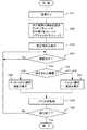
図2において、まず、車両の電源がオンにされることによって、ナビゲーション装置10の電源がオンにされる(ステップS41)。次いで、機器認識手段16によって、操作機器の接続が認識される(ステップS42)。具体的には、機器認識手段16から操作機器の接続を認識するための信号が出力され、タッチパネル18bおよび赤外線リモコン21、さらに、ネットワーク22を介してハプティックリモコン23が認識される。このとき、ハプティックリモコン23のアドレスデータが取得される。
【0043】
次いで、画像信号出力手段17によって、既定の画像信号が出力され、表示手段18に表示される(ステップS43)。既定の画像信号とは、例えば、電源投入後に表示手段18に表示されるメニュー画面の画像信号のように予め定められた画像信号をいう。
【0044】
引き続き、機器認識手段16によって、操作機器からの操作信号の有無に基づき、操作機器が操作されたか否かが判断される(ステップS44)。操作機器が操作されたと判断された場合は、さらに機器認識手段16によって、どの操作機器が操作されたかが判断される(ステップS45)。一方、操作機器が操作されたと判断されなかった場合は、ステップS44に戻る。
【0045】
ステップS45において、操作された機器がタッチパネル18bと判断された場合は、画像信号出力手段17によって、タッチパネル選択画面の画像信号が表示手段18に出力され、表示手段18によって、タッチパネル選択画面が表示される(ステップS46)。一方、ステップS45において、操作された機器が赤外線リモコン21またはハプティックリモコン23と判断された場合は、画像信号出力手段17によって、リモコン選択画面の画像信号が表示手段18に出力され、表示手段18によって、リモコン選択画面が表示される(ステップS47)。なお、タッチパネル選択画面およびリモコン選択画面については後述する。
【0046】
引き続き、制御手段14によって、コマンドが処理される(ステップS48)。例えば、ステップS46において表示されたメニュー画面で選択されたコマンドが実行される。
【0047】
そして、制御手段14によって、表示手段18の表示を終了するか否かが判断される(ステップS49)。例えば、表示手段18に表示されたメニュー画面の表示を終了するアイコンが選択された場合は、表示を終了すると判断される。ステップS49において、表示を終了すると判断された場合は、処理を終了し、表示を終了すると判断されなかった場合は、ステップS44に戻る。
【0048】
ここで、表示手段18に表示されるタッチパネル選択画面およびリモコン選択画面について、図3から図5を参照して説明する。
【0049】
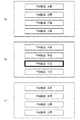
まず、図3に示されたナビゲーションのメニューを例に挙げて説明する。
【0050】
タッチパネル選択画面は、図3(a)に示すように、6個の楕円形のアイコンでコマンドが選択できるようになっている。例えば、車両の搭乗者が「行先」のアイコンを指先またはペン先で接触すれば、「行先」に係る下位のメニューが表示され、車両の行き先が決定できるようになっている。
【0051】
リモコン選択画面は、図3(b)に示すように、6個のボックス型のアイコンでコマンドが選択できるようになっている。図3(b)においては、赤外線リモコン21またはハプティックリモコン23によって選択された「場所を探す」のアイコンが強調表示されていることが示されている。この強調表示は、ハイライト、点滅、アニメーション等によって実行することができる。
【0052】
タッチパネル選択画面とリモコン選択画面とを比較すると、それぞれ以下のような特徴を有している。まず、タッチパネル選択画面においては、タッチパネル18bに接触できる範囲の搭乗者が視認でき、操作できればよく、また、カーソルの移動方向および強調表示等を考慮する必要がない。したがって、アイコンのサイズを小さくすることができるのでアイコンを多数、しかも、任意の位置に配置することができる。
【0053】
一方、リモコン選択画面においては、大きいサイズのアイコンが整列して配置され、また、現在選択されているカーソルの位置が強調表示されている。したがって、車両の後席の搭乗者でもアイコンを容易に視認でき、しかも、カーソルを動かす方向に悩むことなく操作することができる。
【0054】
次に、図4に示されたFM放送の選局メニューを例に挙げて説明する。なお、図1に示されたオーディオ装置24は、FM放送を受信するチューナを備えている。車両の搭乗者は、表示手段18に表示されたFM放送の選局メニューによってFM放送を選局できるようになっている。
【0055】
前述のステップS45において、機器認識手段16によって、操作された機器がタッチパネル18bと判断された場合、図4(a)に示すように、表示手段18にはタッチパネル選択画面が表示される。図4(a)は、FM放送A局からFM放送D局までのいずれかの局を選局するアイコンを示している。
【0056】
図4(a)に示されたタッチパネル選択画面が表示手段18に表示されているとき、ステップS45において、機器認識手段16によって、操作された機器が赤外線リモコン21またはハプティックリモコン23と判断された場合、図(b)に示されたリモコン操作画面に切り替わる。図4(b)は、FM放送局Cが選局されている状態を示している。
【0057】
さらに、図4(b)に示されたリモコン操作画面が表示手段18に表示されているとき、ステップS45において、機器認識手段16によって、操作された機器がタッチパネル18bと判断された場合、すなわち、車両の搭乗者が、図4(b)に示されたいずれかのアイコンに接触した場合は、図(c)に示されたタッチパネル選択画面に切り替わる。
【0058】
以上のように、車両の搭乗者が操作機器を操作したとき、操作機器に対応した画面に直ちに切り替わり、表示手段18に表示されるので、搭乗者は、好みまたは場面に応じて操作機器を選択し、操作することができる。
【0059】
次に、図5に示されたコンテンツ表示画面を例に挙げて説明する。なお、図1に示された携帯電話27は、インターネットに接続され、インターネットからコンテンツを取得するようになっている。また、制御手段14は、ブラウザを備え、携帯電話27が取得したコンテンツを表示手段18に表示するようになっている。
【0060】
図5(a)には、「今日のニュース」のコンテンツ50が示されている。コンテンツ50には、ニュースAのテキスト51と、ニュースAの写真A52と、ニュースBのテキスト53と、ニュースBの写真B54と、前ページに戻るアイコン55と、次ページに進むアイコン56とが示されている。車両の搭乗者は、例えば、ユースBのタイトルを指先で接触することにより、ニュースBの詳細内容が記述されたコンテンツを表示させることができる。
【0061】
図5(a)に示されたコンテンツ50が表示されているときに、車両の搭乗者が、例えば、赤外線リモコン21を操作すれば、図5(b)に示すように、カーソル57が表示される。したがって、車両の搭乗者は、赤外線リモコン21が有するカーソルキーおよびボタンを操作し、例えば、カーソル57を写真B54上に位置に移動させ、写真B54をクリックすることにより、拡大された写真Bを表示させることができる。
【0062】
また、図5(b)に示されたコンテンツ50が表示されているときに、車両の搭乗者が、指先またはペン先でいずれかの場所を接触すれば、カーソル57は消去される。
【0063】
なお、本発明の車載装置は、ナビゲーション装置10に限定されるものではない。また、表示手段18をネットワーク22に接続し、ネットワーク22に接続された機器および装置の情報を表示するよう構成してもよい。また、図2に示されたフローチャートの各ステップをプログラミングし、接続された操作機器を認識する処理と、操作機器に対応した画像信号を出力する処理とをコンピュータに実行させることができる。
【0064】
以上のように、本実施の形態のナビゲーション装置10によれば、機器認識手段16は、タッチパネル18b、赤外線リモコン21等の操作機器を認識し、画像信号出力手段17は、操作機器に対応した画像信号を出力する構成としたので車両の後部座席の搭乗者でも容易に操作することができ、しかも、同一のコマンド選択場面においても、任意の操作機器を操作することができる。
【0065】
【発明の効果】
以上説明したように、本発明によれば、車両の後部座席の搭乗者でも容易に操作することができ、しかも、同一のコマンド選択場面においても、任意の操作機器を操作することができる。
【図面の簡単な説明】
【図1】本発明の実施の形態のナビゲーション装置のブロック図
【図2】本発明の実施の形態のナビゲーション装置の各ステップのフローチャート
【図3】(a)タッチパネル選択画面の一例を示す図
(b)リモコン選択画面の一例を示す図
【図4】(a)タッチパネル選択画面の一例を示す図
(b)リモコン選択画面の一例を示す図
(c)タッチパネル選択画面の一例を示す図
【図5】(a)タッチパネル選択画面の一例を示す図
(b)リモコン選択画面の一例を示す図
【符号の説明】
10 ナビゲーション装置
11 現在位置検出手段
12 目的地入力手段
13 地図データ記憶手段
14 制御手段
15 通信手段
16 機器認識手段
16a 機器認識部
16b 赤外線受光部
17 画像信号出力手段
18 表示手段
18a 表示ユニット
18b タッチパネル
19 音響信号出力手段
20 スピーカ
21 赤外線リモコン
22 ネットワーク
23 ハプティックリモコン
24 オーディオ装置
25 デジタルテレビ
26 ゲートウェイ装置
27 携帯電話
30 車載システム
50 コンテンツ
51、53 テキスト
52 写真A
54 写真B
55、56 アイコン
57 カーソル[0001]
TECHNICAL FIELD OF THE INVENTION
The present invention relates to a vehicle-mounted device, and more particularly, to a vehicle-mounted device operated by a remote control device, a touch panel, or the like.
[0002]
[Prior art]
A conventional in-vehicle device has a touch panel, a display for displaying a predetermined image, a pen-shaped remote control unit, a position specifying unit for specifying a position on the display instructed to be contacted by the remote control unit, and a remote control unit. A first communication unit for communicating. The remote control unit includes a storage unit that stores the specified position data, a display unit that displays the position data, and a second communication unit that communicates with the first communication unit.
[0003]
In a conventional in-vehicle device, first, a display image displayed on a display, for example, an arbitrary position on a map is instructed to contact by a remote control unit. Next, the position specified by the contact is specified by the position specifying unit. Then, the position data is transmitted to the remote control unit by the first communication unit. In the remote control unit, the position data is received by the second communication unit and stored in the storage unit. Further, the position data stored in the storage unit is transmitted to the first communication unit by the second communication unit, and is displayed on the display.
[0004]
As described above, the conventional in-vehicle device specifies the position on the display image by the contact instruction of the pen-shaped remote controller, stores the specified position data in the remote controller, and reproduces the position data. The position of the store to be used repeatedly can be displayed on the display (for example, see Patent Document 1).
[0005]
[Patent Document 1]
Japanese Patent Application Laid-Open No. 11-311539 (page 3-7, FIG. 1)
[0006]
[Problems to be solved by the invention]
However, in such a conventional in-vehicle device, when pointing to a position on a display image, the pen-shaped remote control unit must touch the touch panel, so that the passenger in the rear seat cannot easily operate. was there.
[0007]
Further, in order to solve the above-described problem, the conventional in-vehicle device has a configuration in which a command is selected by one of an operation of a touch panel and an operation of an operation key of a remote control unit. It is determined in advance for each scene to be executed by an operation limited to such an operation. Therefore, there is a problem that the operator can operate only with a predetermined operation device for each command selection scene, and cannot use the operation device properly for each command selection scene.
[0008]
The present invention has been made in order to solve such a problem, and can be easily operated even by a passenger in the rear seat of the vehicle.Moreover, even in the same command selection scene, any operation device can be used. An object of the present invention is to provide an in-car device that can be operated.
[0009]
[Means for Solving the Problems]
The in-vehicle device according to the present invention has a configuration characterized by comprising: device recognition means for recognizing an operation device including a remote control device and a touch panel; and image signal output means for outputting an image signal corresponding to the operation device. are doing.
[0010]
With this configuration, the image signal output unit outputs an image signal corresponding to the operation device including the remote control device and the touch panel, so that even a passenger in the rear seat of the vehicle can easily operate the image signal output device, and furthermore, the same command selection can be performed. In a scene, any operation device can be operated.
[0011]
Further, the in-vehicle device of the present invention has a configuration in which the device recognizing means recognizes the operating device connected via a network.
[0012]
With this configuration, the device recognizing unit recognizes the operating device connected via the network, so that the occupant of the vehicle can operate any operating device connected to the network even in the same command selection scene. Can be.
[0013]
Further, the in-vehicle device of the present invention has a configuration in which the device recognizing means recognizes the operating device based on address data on the network that the operating device has.
[0014]
With this configuration, the device recognizing unit recognizes the operating device based on the address data on the network, so that the operating device can be accurately recognized.
[0015]
Further, in the vehicle-mounted device according to the present invention, the image signal output unit outputs one of an image signal of a remote control selection screen on which an operation command is selected by the remote control device and a touch panel selection screen on which an operation command is selected by the touch panel. It has a configuration characterized by the following.
[0016]
With this configuration, the image signal output unit outputs any one of the image signals of the remote control selection screen and the touch panel selection screen, so that the passenger of the vehicle can operate any operation device even in the same command selection scene. Can be.
[0017]
Further, in the vehicle-mounted device according to the present invention, when the image signal output unit outputs the image signal of the remote control selection screen, the image signal output unit outputs an image signal for highlighting a display section of the operation command selected by the remote control device. It has a configuration characterized by the following.
[0018]
With this configuration, when the image signal output unit outputs the image signal of the remote control selection screen, the image signal output unit outputs an image signal for highlighting the display unit of the operation command, so that the occupant of the vehicle is currently selected by the remote control device. You can easily find the operation command you are using.
[0019]
Further, in the vehicle-mounted device according to the present invention, the image signal output means outputs an image signal including a cursor signal operated by a cursor key of the remote control device when outputting the image signal of the remote control selection screen. It has a configuration that
[0020]
With this configuration, the image signal output unit outputs the image signal including the cursor signal when outputting the image signal of the remote control selection screen.Therefore, the occupant of the vehicle moves the cursor to a desired position using the remote control device, Commands can be executed.
[0021]
Further, the in-vehicle system according to the present invention is connected to a network, a device recognizing means for recognizing an operation device including a remote control device and a touch panel, an image signal output means for outputting an image signal corresponding to the operation device, And an operating device for operating the in-vehicle device, and a display device for displaying a predetermined image.
[0022]
With this configuration, the image signal output unit includes the remote control device and the touch panel, and outputs an image signal corresponding to the operation device connected to the network, so that the passenger in the rear seat of the vehicle can easily operate the image signal, In addition, any operation device can be operated even in the same command selection scene.
[0023]
An image display method for an in-vehicle device according to the present invention has a method characterized by outputting an image signal corresponding to the operating device after recognizing the connected operating device.
[0024]
According to this method, after recognizing the connected operation device, an image signal corresponding to the operation device is output.
[0025]
An image display program for an in-vehicle device according to the present invention is a program for causing a computer to execute a process of recognizing a connected operation device and a process of outputting an image signal corresponding to the operation device.
[0026]
With this program, the computer executes a process of recognizing the connected operation device and a process of outputting an image signal corresponding to the operation device.
[0027]
BEST MODE FOR CARRYING OUT THE INVENTION
Hereinafter, embodiments of the present invention will be described with reference to the drawings. Note that a navigation device will be described as an example of a vehicle-mounted device according to an embodiment of the present invention.
[0028]
First, the configuration of the navigation device according to the present embodiment will be described.
[0029]
As shown in FIG. 1, a
[0030]
The device recognizing means 16 includes a
[0031]
The
[0032]
Note that the
[0033]
The current position detecting means 11 is constituted by, for example, a GPS (Global Positioning System) unit, and detects the current position of the vehicle by a GPS radio wave. The destination input means 12 is constituted by, for example, a cursor key, and inputs a destination of the vehicle by specifying a position on the map displayed on the display means 18 with the cursor key. The map data storage means 13 is constituted by, for example, a CD-ROM, and stores map data.
[0034]
The
[0035]
The communication unit 15 includes, for example, a transceiver, a microprocessor, a memory, and the like, and communicates with the network 22 based on a predetermined communication protocol. When the network 22 is an in-vehicle LAN, data is transmitted and received according to a vehicle-specific communication protocol including CAN (Controller Area Network), D2B (Digital Data Bus), and the like.
[0036]
The
[0037]
The haptic
[0038]
The infrared
[0039]
The image signal output unit 17 includes an image processing processor, a memory, and the like. In this memory, predetermined image signals corresponding to operating devices such as the
[0040]
The
[0041]
Next, the operation of the
[0042]
In FIG. 2, first, the power of the vehicle is turned on, so that the power of the
[0043]
Next, a predetermined image signal is output by the image signal output means 17 and displayed on the display means 18 (step S43). The predetermined image signal is a predetermined image signal such as an image signal of a menu screen displayed on the
[0044]
Subsequently, the device recognizing unit 16 determines whether or not the operating device has been operated based on the presence or absence of the operation signal from the operating device (step S44). If it is determined that the operating device has been operated, the device recognizing unit 16 further determines which operating device has been operated (step S45). On the other hand, if it is not determined that the operation device has been operated, the process returns to step S44.
[0045]
If it is determined in step S45 that the operated device is the
[0046]
Subsequently, the command is processed by the control means 14 (step S48). For example, the command selected on the menu screen displayed in step S46 is executed.
[0047]
Then, the
[0048]
Here, the touch panel selection screen and the remote control selection screen displayed on the
[0049]
First, the navigation menu shown in FIG. 3 will be described as an example.
[0050]
On the touch panel selection screen, as shown in FIG. 3A, commands can be selected with six elliptical icons. For example, if the passenger of the vehicle touches the “destination” icon with a fingertip or a pen tip, a lower menu related to “destination” is displayed, and the destination of the vehicle can be determined.
[0051]
As shown in FIG. 3B, the remote control selection screen allows the user to select a command using six box-shaped icons. FIG. 3B shows that the icon of “Find a place” selected by the infrared
[0052]
When the touch panel selection screen and the remote control selection screen are compared, each has the following features. First, on the touch panel selection screen, it is sufficient that the occupant in the range that can touch the
[0053]
On the other hand, on the remote control selection screen, icons of large size are arranged and arranged, and the position of the currently selected cursor is highlighted. Therefore, the icon can be easily recognized even by a passenger in the rear seat of the vehicle, and the operation can be performed without worrying about the direction in which the cursor is moved.
[0054]
Next, a description will be given by taking the FM broadcast channel selection menu shown in FIG. 4 as an example. Note that the
[0055]
In step S45 described above, if the operated device is determined to be the
[0056]
When the touch panel selection screen shown in FIG. 4A is displayed on the
[0057]
Further, when the remote control operation screen shown in FIG. 4B is displayed on the
[0058]
As described above, when the occupant of the vehicle operates the operating device, the screen is immediately switched to the screen corresponding to the operating device and is displayed on the
[0059]
Next, the content display screen shown in FIG. 5 will be described as an example. The
[0060]
FIG. 5A illustrates the
[0061]
When the passenger of the vehicle operates, for example, the infrared
[0062]
Also, if the occupant of the vehicle touches any place with his fingertip or pen tip while the
[0063]
Note that the in-vehicle device of the present invention is not limited to the
[0064]
As described above, according to the
[0065]
【The invention's effect】
As described above, according to the present invention, even a passenger in the rear seat of the vehicle can easily operate, and even in the same command selection scene, any operation device can be operated.
[Brief description of the drawings]
FIG. 1 is a block diagram of a navigation device according to an embodiment of the present invention. FIG. 2 is a flowchart of each step of the navigation device according to an embodiment of the present invention. FIG. 3A shows an example of a touch panel selection screen ( FIG. 4 (a) shows an example of a touch panel selection screen, FIG. 4 (b) shows an example of a remote control selection screen, and FIG. 4 (c) shows an example of a touch panel selection screen. (A) A diagram showing an example of a touch panel selection screen (b) A diagram showing an example of a remote control selection screen
DESCRIPTION OF
54 Photo B
55, 56
Claims (9)
Translated fromJapanesePriority Applications (1)
| Application Number | Priority Date | Filing Date | Title |
|---|---|---|---|
| JP2003114265AJP2004317412A (en) | 2003-04-18 | 2003-04-18 | In-vehicle equipment |
Applications Claiming Priority (1)
| Application Number | Priority Date | Filing Date | Title |
|---|---|---|---|
| JP2003114265AJP2004317412A (en) | 2003-04-18 | 2003-04-18 | In-vehicle equipment |
Publications (1)
| Publication Number | Publication Date |
|---|---|
| JP2004317412Atrue JP2004317412A (en) | 2004-11-11 |
Family
ID=33473917
Family Applications (1)
| Application Number | Title | Priority Date | Filing Date |
|---|---|---|---|
| JP2003114265APendingJP2004317412A (en) | 2003-04-18 | 2003-04-18 | In-vehicle equipment |
Country Status (1)
| Country | Link |
|---|---|
| JP (1) | JP2004317412A (en) |
Cited By (3)
| Publication number | Priority date | Publication date | Assignee | Title |
|---|---|---|---|---|
| JP2013123973A (en)* | 2011-12-14 | 2013-06-24 | Nippon Seiki Co Ltd | Information provision device for vehicle |
| JP2013156923A (en)* | 2012-01-31 | 2013-08-15 | Canon Inc | Electronic apparatus, control method thereof, program, and recording medium |
| US11091036B2 (en) | 2005-04-14 | 2021-08-17 | Volkswagen Ag | Method for representing items of information in a means of transportation and instrument cluster for a motor vehicle |
Citations (6)
| Publication number | Priority date | Publication date | Assignee | Title |
|---|---|---|---|---|
| JPH05207566A (en)* | 1992-01-28 | 1993-08-13 | Matsushita Electric Works Ltd | Control panel |
| JPH07319340A (en)* | 1994-05-20 | 1995-12-08 | Fuji Xerox Co Ltd | Control panel device for image forming device |
| JPH10275070A (en)* | 1997-03-31 | 1998-10-13 | Toyota Motor Corp | Display operation system |
| JP2001103063A (en)* | 1999-09-29 | 2001-04-13 | Matsushita Electric Ind Co Ltd | Network monitoring device, monitoring method, and recording medium |
| JP2003042795A (en)* | 2001-07-30 | 2003-02-13 | Matsushita Electric Ind Co Ltd | Navigation device |
| JP2004252820A (en)* | 2003-02-21 | 2004-09-09 | Matsushita Electric Ind Co Ltd | Image display device and car navigation system |
- 2003
- 2003-04-18JPJP2003114265Apatent/JP2004317412A/enactivePending
Patent Citations (6)
| Publication number | Priority date | Publication date | Assignee | Title |
|---|---|---|---|---|
| JPH05207566A (en)* | 1992-01-28 | 1993-08-13 | Matsushita Electric Works Ltd | Control panel |
| JPH07319340A (en)* | 1994-05-20 | 1995-12-08 | Fuji Xerox Co Ltd | Control panel device for image forming device |
| JPH10275070A (en)* | 1997-03-31 | 1998-10-13 | Toyota Motor Corp | Display operation system |
| JP2001103063A (en)* | 1999-09-29 | 2001-04-13 | Matsushita Electric Ind Co Ltd | Network monitoring device, monitoring method, and recording medium |
| JP2003042795A (en)* | 2001-07-30 | 2003-02-13 | Matsushita Electric Ind Co Ltd | Navigation device |
| JP2004252820A (en)* | 2003-02-21 | 2004-09-09 | Matsushita Electric Ind Co Ltd | Image display device and car navigation system |
Cited By (3)
| Publication number | Priority date | Publication date | Assignee | Title |
|---|---|---|---|---|
| US11091036B2 (en) | 2005-04-14 | 2021-08-17 | Volkswagen Ag | Method for representing items of information in a means of transportation and instrument cluster for a motor vehicle |
| JP2013123973A (en)* | 2011-12-14 | 2013-06-24 | Nippon Seiki Co Ltd | Information provision device for vehicle |
| JP2013156923A (en)* | 2012-01-31 | 2013-08-15 | Canon Inc | Electronic apparatus, control method thereof, program, and recording medium |
Similar Documents
| Publication | Publication Date | Title |
|---|---|---|
| KR101838859B1 (en) | Portable terminal device, on-vehicle device, and on-vehicle system | |
| US10719146B2 (en) | Input device with plurality of touch pads for vehicles | |
| JP5225820B2 (en) | Input device, vehicle periphery monitoring device, icon switch selection method and program | |
| JP5555555B2 (en) | In-vehicle device that cooperates with a portable device and realizes an input operation possible for the portable device | |
| KR101495190B1 (en) | Image display device and operation method of the image display device | |
| KR101326994B1 (en) | A contents control system and method for optimizing information of display wherein mobile device | |
| KR101893148B1 (en) | Mobile terminal and method for controlling a vehicle using the same | |
| US20140281957A1 (en) | System and Method for Transitioning Between Operational Modes of an In-Vehicle Device Using Gestures | |
| US20100030469A1 (en) | Contents navigation apparatus and method thereof | |
| JP5754410B2 (en) | Display device | |
| KR101542495B1 (en) | Method for displaying information for mobile terminal and apparatus thereof | |
| JP6084021B2 (en) | Display system, display device, display method, and program | |
| JP2013191979A (en) | On-vehicle apparatus, portable terminal, and program for portable terminal | |
| JP2019133395A (en) | Input device | |
| JP2004317412A (en) | In-vehicle equipment | |
| JP2009163435A (en) | Information terminal, computer program, and display method | |
| US20160253088A1 (en) | Display control apparatus and display control method | |
| US10061505B2 (en) | Electronic device and operation input method | |
| JP6798608B2 (en) | Navigation system and navigation program | |
| KR101405566B1 (en) | A sequential image switching method and apparatus thereof using dynamic touch interaction | |
| JP5040402B2 (en) | Navigation device and navigation screen display method | |
| JP6397530B2 (en) | Display device | |
| WO2018090368A1 (en) | Method and apparatus for controlling a mobile terminal | |
| JP2018173311A (en) | Navigation system and navigation program | |
| JP2019135625A (en) | Image display device |
Legal Events
| Date | Code | Title | Description |
|---|---|---|---|
| A621 | Written request for application examination | Free format text:JAPANESE INTERMEDIATE CODE: A621 Effective date:20051121 | |
| A711 | Notification of change in applicant | Free format text:JAPANESE INTERMEDIATE CODE: A711 Effective date:20051121 | |
| A521 | Request for written amendment filed | Free format text:JAPANESE INTERMEDIATE CODE: A821 Effective date:20051121 | |
| A977 | Report on retrieval | Free format text:JAPANESE INTERMEDIATE CODE: A971007 Effective date:20080110 | |
| A131 | Notification of reasons for refusal | Free format text:JAPANESE INTERMEDIATE CODE: A131 Effective date:20080122 | |
| A02 | Decision of refusal | Free format text:JAPANESE INTERMEDIATE CODE: A02 Effective date:20080708 |