JP2004310388A - Special effector, address signal generating unit, address signal generating method, and address signal generating program - Google Patents
Special effector, address signal generating unit, address signal generating method, and address signal generating programDownload PDFInfo
- Publication number
- JP2004310388A JP2004310388AJP2003102349AJP2003102349AJP2004310388AJP 2004310388 AJP2004310388 AJP 2004310388AJP 2003102349 AJP2003102349 AJP 2003102349AJP 2003102349 AJP2003102349 AJP 2003102349AJP 2004310388 AJP2004310388 AJP 2004310388A
- Authority
- JP
- Japan
- Prior art keywords
- image
- address signal
- frame buffer
- image signal
- generating
- Prior art date
- Legal status (The legal status is an assumption and is not a legal conclusion. Google has not performed a legal analysis and makes no representation as to the accuracy of the status listed.)
- Granted
Links
- 238000000034methodMethods0.000titleclaimsdescription38
- 239000012636effectorSubstances0.000titleabstract2
- 230000000694effectsEffects0.000claimsabstractdescription209
- 230000007274generation of a signal involved in cell-cell signalingEffects0.000claimsdescription51
- 230000014509gene expressionEffects0.000claimsdescription21
- 238000010586diagramMethods0.000description36
- 230000006870functionEffects0.000description33
- ORILYTVJVMAKLC-UHFFFAOYSA-NAdamantaneNatural productsC1C(C2)CC3CC1CC2C3ORILYTVJVMAKLC-UHFFFAOYSA-N0.000description29
- 230000001739rebound effectEffects0.000description11
- 238000006243chemical reactionMethods0.000description8
- 229910003460diamondInorganic materials0.000description8
- 239000010432diamondSubstances0.000description8
- 239000011159matrix materialSubstances0.000description5
- 238000007781pre-processingMethods0.000description4
- 230000002194synthesizing effectEffects0.000description4
- 230000009191jumpingEffects0.000description2
- 230000015572biosynthetic processEffects0.000description1
- 238000003786synthesis reactionMethods0.000description1
- 230000009466transformationEffects0.000description1
Images


Classifications
- H—ELECTRICITY
- H04—ELECTRIC COMMUNICATION TECHNIQUE
- H04N—PICTORIAL COMMUNICATION, e.g. TELEVISION
- H04N9/00—Details of colour television systems
- H04N9/64—Circuits for processing colour signals
- H04N9/74—Circuits for processing colour signals for obtaining special effects
- G—PHYSICS
- G09—EDUCATION; CRYPTOGRAPHY; DISPLAY; ADVERTISING; SEALS
- G09G—ARRANGEMENTS OR CIRCUITS FOR CONTROL OF INDICATING DEVICES USING STATIC MEANS TO PRESENT VARIABLE INFORMATION
- G09G5/00—Control arrangements or circuits for visual indicators common to cathode-ray tube indicators and other visual indicators
- G09G5/36—Control arrangements or circuits for visual indicators common to cathode-ray tube indicators and other visual indicators characterised by the display of a graphic pattern, e.g. using an all-points-addressable [APA] memory
- G09G5/39—Control of the bit-mapped memory
- G09G5/395—Arrangements specially adapted for transferring the contents of the bit-mapped memory to the screen
- G—PHYSICS
- G09—EDUCATION; CRYPTOGRAPHY; DISPLAY; ADVERTISING; SEALS
- G09G—ARRANGEMENTS OR CIRCUITS FOR CONTROL OF INDICATING DEVICES USING STATIC MEANS TO PRESENT VARIABLE INFORMATION
- G09G2340/00—Aspects of display data processing
- G09G2340/04—Changes in size, position or resolution of an image
- G09G2340/0492—Change of orientation of the displayed image, e.g. upside-down, mirrored
- G—PHYSICS
- G09—EDUCATION; CRYPTOGRAPHY; DISPLAY; ADVERTISING; SEALS
- G09G—ARRANGEMENTS OR CIRCUITS FOR CONTROL OF INDICATING DEVICES USING STATIC MEANS TO PRESENT VARIABLE INFORMATION
- G09G5/00—Control arrangements or circuits for visual indicators common to cathode-ray tube indicators and other visual indicators
- G09G5/36—Control arrangements or circuits for visual indicators common to cathode-ray tube indicators and other visual indicators characterised by the display of a graphic pattern, e.g. using an all-points-addressable [APA] memory
- G09G5/39—Control of the bit-mapped memory
- G09G5/395—Arrangements specially adapted for transferring the contents of the bit-mapped memory to the screen
- G09G5/397—Arrangements specially adapted for transferring the contents of two or more bit-mapped memories to the screen simultaneously, e.g. for mixing or overlay
Landscapes
- Engineering & Computer Science (AREA)
- Physics & Mathematics (AREA)
- Computer Hardware Design (AREA)
- General Physics & Mathematics (AREA)
- Theoretical Computer Science (AREA)
- Multimedia (AREA)
- Signal Processing (AREA)
- Studio Circuits (AREA)
- Image Processing (AREA)
- Controls And Circuits For Display Device (AREA)
- Image Input (AREA)
- Processing Or Creating Images (AREA)
Abstract
Description
Translated fromJapanese【0001】
【発明の属する技術分野】
本発明は、画像特殊効果に関するものであり、詳しくは、リードアドレスコントロール方式を用いた画像特殊効果を実行する特殊効果装置に関する。
【0002】
【従来の技術】
フレームバッファに格納した画像信号に対して、読み出し時のアドレスを変換して読み出すことで、画像特殊効果を施すリードアドレスコントロール方式が考案、実施されている(例えば、特許文献1参照。)。
【0003】
【特許文献1】
特開平10−145672号公報
【0004】
【発明が解決しようとする課題】
上述したリードアドレスコントロール方式においては、画像の拡大、縮小、回転、移動などといった、極めて単純な画像特殊効果についてのみ考案、実施されている。
【0005】
そこで、本発明は、上述したようなリードアドレス方式を用いた、全く新しい画像特殊効果を実行する特殊効果装置、アドレス信号生成装置、アドレス信号生成方法及びアドレス信号生成プログラムを提供することを目的とする。
【0006】
【課題を解決するための手段】
上述の目的を達成するために、本発明に係る特殊効果装置は、アドレス信号に基づいてフレームバッファから画像信号を読み出すことにより、上記フレームバッファから読み出される画像信号に所望の特殊効果を与える特殊効果装置において、上記フレームバッファに記憶された画像信号に対応する画像が、表示時に表示領域の外縁に与える任意の点を回転中心として回転移動し、上記画像が表示領域の外側に消え去るような特殊効果が得られるように、上記フレームバッファに記憶された上記画像信号の読み出しアドレス信号を生成するアドレス信号生成手段を備えることを特徴とする。
【0007】
上述の目的を達成するために、本発明に係るアドレス信号生成装置は、フレームバッファから画像信号を読み出すアドレス信号を生成するアドレス信号生成装置において、上記フレームバッファに記憶された画像信号に対応する画像が、表示時に表示領域の外縁に与える任意の点を回転中心として回転移動し、上記画像が表示領域の外側に消え去るような特殊効果が得られるように、上記フレームバッファに記憶された上記画像信号の読み出しアドレス信号を生成するアドレス信号生成手段を備えることを特徴とする。
【0008】
上述の目的を達成するために、本発明に係るアドレス信号生成方法は、フレームバッファから画像信号を読み出すアドレス信号を生成するアドレス信号生成方法において、上記フレームバッファに記憶された画像信号に対応する画像が、表示時に表示領域の外縁に与える任意の点を回転中心として回転移動し、上記画像が表示領域の外側に消え去るような特殊効果が得られるように、上記フレームバッファに記憶された上記画像信号の読み出しアドレス信号を生成するアドレス信号生成工程を備えることを特徴とする。
【0009】
上述の目的を達成するために、本発明に係るアドレス信号生成プログラムは、フレームバッファから画像信号を読み出すアドレス信号を生成する工程をコンピュータに実行させるアドレス信号生成プログラムにおいて、上記フレームバッファに記憶された画像信号に対応する画像が、表示時に表示領域の外縁に与える任意の点を回転中心として回転移動し、上記画像が表示領域の外側に消え去るような特殊効果が得られるように、上記フレームバッファに記憶された上記画像信号の読み出しアドレス信号を生成するアドレス信号生成工程をコンピュータに実行させる。
【0010】
上述の目的を達成するために、本発明に係る特殊効果装置は、アドレス信号に基づいてフレームバッファから画像信号を読み出すことにより、上記フレームバッファから読み出される画像信号に所望の特殊効果を与える特殊効果装置において、上記フレームバッファに記憶された画像信号に対応する画像が、表示時に直線状の境界線を有する2つの部分画像に分割され、当該境界線が表示領域の外縁とが交差することになる2つの交点のうちいずれか一方を回転中心として、互いに相反する方向に回転移動し、上記部分画像がそれぞれ表示領域の外側に消え去るような特殊効果が得られるように、上記フレームバッファに記憶された上記画像信号の読み出しアドレス信号を生成するアドレス信号生成手段を備えることを特徴とする。
【0011】
上述の目的を達成するために、本発明に係るアドレス信号生成装置は、フレームバッファから画像信号を読み出すアドレス信号を生成するアドレス信号生成装置において、上記フレームバッファに記憶された画像信号に対応する画像が、表示時に直線状の境界線を有する2つの部分画像に分割され、当該境界線が表示領域の外縁とが交差することになる2つの交点のうちいずれか一方を回転中心として、互いに相反する方向に回転移動し、上記部分画像がそれぞれ表示領域の外側に消え去るような特殊効果が得られるように、上記フレームバッファに記憶された上記画像信号の読み出しアドレス信号を生成するアドレス信号生成手段を備えることを特徴とする。
【0012】
上述の目的を達成するために、本発明に係るアドレス信号生成方法は、フレームバッファから画像信号を読み出すアドレス信号を生成するアドレス信号生成方法において、上記フレームバッファに記憶された画像信号に対応する画像が、表示時に直線状の境界線を有する2つの部分画像に分割され、当該境界線が表示領域の外縁とが交差することになる2つの交点のうちいずれか一方を回転中心として、互いに相反する方向に回転移動し、上記部分画像がそれぞれ表示領域の外側に消え去るような特殊効果が得られるように、上記フレームバッファに記憶された上記画像信号の読み出しアドレス信号を生成するアドレス信号生成工程を備えることを特徴とする。
【0013】
上述の目的を達成するために、本発明に係るアドレス信号生成プログラムは、フレームバッファから画像信号を読み出すアドレス信号を生成する工程をコンピュータに実行させるアドレス信号生成プログラムにおいて、上記フレームバッファに記憶された画像信号に対応する画像が、表示時に直線状の境界線を有する2つの部分画像に分割され、当該境界線が表示領域の外縁とが交差することになる2つの交点のうちいずれか一方を回転中心として、互いに相反する方向に回転移動し、上記部分画像がそれぞれ表示領域の外側に消え去るような特殊効果が得られるように、上記フレームバッファに記憶された上記画像信号の読み出しアドレス信号を生成するアドレス信号生成工程をコンピュータに実行させる。
【0014】
上述の目的を達成するために、本発明に係る特殊効果装置は、アドレス信号に基づいてフレームバッファから画像信号を読み出すことにより、上記フレームバッファから読み出される画像信号に所望の特殊効果を与える特殊効果装置において、上記フレームバッファに記憶された画像信号に対応する画像が、表示時に直線状の境界線を有する複数の部分画像に分割され、各部分画像がそれぞれ表示領域の外側に消え去るように平行移動するような特殊効果が得られるように、上記フレームバッファに記憶された上記画像信号の読み出しアドレス信号を生成するアドレス信号生成手段を備えることを特徴とする。
【0015】
上述の目的を達成するために、本発明に係るアドレス信号生成装置は、フレームバッファから画像信号を読み出すアドレス信号を生成するアドレス信号生成装置において、上記フレームバッファに記憶された画像信号に対応する画像が、表示時に直線状の境界線を有する複数の部分画像に分割され、各部分画像がそれぞれ表示領域の外側に消え去るように平行移動するような特殊効果が得られるように、上記フレームバッファに記憶された上記画像信号の読み出しアドレス信号を生成するアドレス信号生成手段を備えることを特徴とする。
【0016】
上述の目的を達成するために、本発明に係るアドレス信号生成方法は、フレームバッファから画像信号を読み出すアドレス信号を生成するアドレス信号生成方法において、上記フレームバッファに記憶された画像信号に対応する画像が、表示時に直線状の境界線を有する複数の部分画像に分割され、各部分画像がそれぞれ表示領域の外側に消え去るように平行移動するような特殊効果が得られるように、上記フレームバッファに記憶された上記画像信号の読み出しアドレス信号を生成するアドレス信号生成工程を備えることを特徴とする。
【0017】
上述の目的を達成するために、本発明に係るアドレス信号生成プログラムは、フレームバッファから画像信号を読み出すアドレス信号を生成する工程をコンピュータに実行させるアドレス信号生成プログラムにおいて、上記フレームバッファに記憶された画像信号に対応する画像が、表示時に直線状の境界線を有する複数の部分画像に分割され、各部分画像がそれぞれ表示領域の外側に消え去るように平行移動するような特殊効果が得られるように、上記フレームバッファに記憶された上記画像信号の読み出しアドレス信号を生成するアドレス信号生成工程をコンピュータに実行させる。
【0018】
上述の目的を達成するために、本発明に係る特殊効果装置は、アドレス信号に基づいてフレームバッファから画像信号を読み出すことにより、上記フレームバッファから読み出される画像信号に所望の特殊効果を与える特殊効果装置において、上記フレームバッファに記憶された画像信号に対応する画像が、表示時に所定の関数で与えられる波形の境界線を有する複数の部分画像に分割され、各部分画像がそれぞれ表示領域の外側に消え去るように平行移動するような特殊効果が得られるように、上記フレームバッファに記憶された上記画像信号の読み出しアドレス信号を生成するアドレス信号生成手段を備えることを特徴とする。
【0019】
上述の目的を達成するために、本発明に係るアドレス信号生成装置は、フレームバッファから画像信号を読み出すアドレス信号を生成するアドレス信号生成装置において、上記フレームバッファに記憶された画像信号に対応する画像が、表示時に所定の関数で与えられる波形の境界線を有する複数の部分画像に分割され、各部分画像がそれぞれ表示領域の外側に消え去るように平行移動するような特殊効果が得られるように、上記フレームバッファに記憶された上記画像信号の読み出しアドレス信号を生成するアドレス信号生成手段を備えることを特徴とする。
【0020】
上述の目的を達成するために、本発明に係るアドレス信号生成方法は、フレームバッファから画像信号を読み出すアドレス信号を生成するアドレス信号生成方法において、上記フレームバッファに記憶された画像信号に対応する画像が、表示時に所定の関数で与えられる波形の境界線を有する複数の部分画像に分割され、各部分画像がそれぞれ表示領域の外側に消え去るように平行移動するような特殊効果が得られるように、上記フレームバッファに記憶された上記画像信号の読み出しアドレス信号を生成するアドレス信号生成工程を備えることを特徴とする。
【0021】
上述の目的を達成するために、本発明に係るアドレス信号生成プログラムは、フレームバッファから画像信号を読み出すアドレス信号を生成する工程をコンピュータに実行させるアドレス信号生成プログラムにおいて、上記フレームバッファに記憶された画像信号に対応する画像が、表示時に所定の関数で与えられる波形の境界線を有する複数の部分画像に分割され、各部分画像がそれぞれ表示領域の外側に消え去るように平行移動するような特殊効果が得られるように、上記フレームバッファに記憶された上記画像信号の読み出しアドレス信号を生成するアドレス信号生成工程をコンピュータに実行させる。
【0022】
上述の目的を達成するために、本発明に係る特殊効果装置は、アドレス信号に基づいてフレームバッファから画像信号を読み出すことにより、上記フレームバッファから読み出される画像信号に所望の特殊効果を与える特殊効果装置において、上記フレームバッファに記憶された画像信号に対応する画像が、表示時に表示領域の外側から飛び込むように出現して、当該画像の出現側とは反対側の表示領域外縁で跳ね返り、所定回数の跳ね返りの後、表示領域の中央まで移動するような特殊効果が得られるように、上記フレームバッファに記憶された上記画像信号の読み出しアドレス信号を生成するアドレス信号生成手段を備えることを特徴とする。
【0023】
上述の目的を達成するために、本発明に係るアドレス信号生成装置は、フレームバッファから画像信号を読み出すアドレス信号を生成するアドレス信号生成装置において、上記フレームバッファに記憶された画像信号に対応する画像が、表示時に表示領域の外側から飛び込むように出現して、当該画像の出現側とは反対側の表示領域外縁で跳ね返り、所定回数の跳ね返りの後、表示領域の中央まで移動するような特殊効果が得られるように、上記フレームバッファに記憶された上記画像信号の読み出しアドレス信号を生成するアドレス信号生成手段を備えることを特徴とする。
【0024】
上述の目的を達成するために、本発明に係るアドレス信号生成方法は、フレームバッファから画像信号を読み出すアドレス信号を生成するアドレス信号生成方法において、上記フレームバッファに記憶された画像信号に対応する画像が、表示時に表示領域の外側から飛び込むように出現して、当該画像の出現側とは反対側の表示領域外縁で跳ね返り、所定回数の跳ね返りの後、表示領域の中央まで移動するような特殊効果が得られるように、上記フレームバッファに記憶された上記画像信号の読み出しアドレス信号を生成するアドレス信号生成工程を備えることを特徴とする。
【0025】
上述の目的を達成するために、本発明に係るアドレス信号生成プログラムは、フレームバッファから画像信号を読み出すアドレス信号を生成する工程をコンピュータに実行させるアドレス信号生成プログラムにおいて、上記フレームバッファに記憶された画像信号に対応する画像が、表示時に表示領域の外側から飛び込むように出現して、当該画像の出現側とは反対側の表示領域外縁で跳ね返り、所定回数の跳ね返りの後、表示領域の中央まで移動するような特殊効果が得られるように、上記フレームバッファに記憶された上記画像信号の読み出しアドレス信号を生成するアドレス信号生成工程をコンピュータに実行させる。
【0026】
【発明の実施の形態】
以下、本発明に係る特殊効果装置、アドレス信号生成装置、アドレス信号生成方法及びアドレス信号生成プログラムの実施の形態を図面を参照にして詳細に説明する。
【0027】
図1を用いて、本発明の実施の形態として示す画像特殊効果装置の構成について説明をする。画像特殊効果装置1は、デジタル化されたビデオ信号を入力し、所定の画像特殊効果が得られるように出力する装置である。画像特殊効果装置1では、入力されたデジタルビデオ信号に画像特殊効果を施すための方式として、リードアドレスコントロール方式が採用されている。リードアドレスコントロール方式は、画像フレームを形成している画素データを読み出す際のアドレスを変えることで様々な画像特殊効果を施すことができる。なお、以下の説明においては、画像特殊効果を単に特殊効果と呼ぶことにする。
【0028】
図1に示すように画像特殊効果装置1は、フレームバッファ2と、リードアドレスジェネレータ3と、フレームバッファ4と、画像合成部5とを備えている。
【0029】
フレームバッファ2は、入力されるデジタルビデオ信号をフレーム単位で一時的に格納するバッファメモリである。フレームバッファ2は、メモリ容量に応じて、数フレーム分の画像データを格納することができる。フレームバッファ2に入力されるデジタルビデオ信号は、2次元空間であるフレーム上の位置を示すシーケンシャルなライトアドレス(X,Y)が与えられ、フレームバッファ2に格納される。つまり、フレームバッファ2に入力されたデジタルビデオ信号は、フレームバッファ2のメモリ領域内のアドレス(X,Y)に画像データとして格納されることになる。
【0030】
なお、ライトアドレス(X,Y)と、アドレス(X,Y)は、同じものである。つまり、ライトアドレス(X,Y)は、デジタルビデオ信号をフレームバッファ2に書き込む際のアドレスであり、フレームバッファ2に書き込まれた後においては、アドレス(X,Y)としている。以下の説明においては、フレームバッファ2に既にフレーム単位の画像データが格納されているものとし、画像データが格納されているアドレスは、アドレス(X,Y)とする。
【0031】
また、フレームバッファ2に格納される画像データは、後述する特殊効果を実行するのに有効となる領域の画像データを抽出するクロップ処理がなされているものとする。
【0032】
リードアドレスジェネレータ3は、当該画像特殊効果装置1で採用されているリードアドレスコントロール方式に基づいて、フレームバッファ2に格納された画像データを読み出す際のリードアドレスを特殊効果の種別に応じて算出する。リードアドレスジェネレータ3は、算出したリードアドレスを用いて、フレームバッファ2に格納された画像データを読み出すことで、特殊効果を施した画像を出力させる。
【0033】
具体的には、リードアドレスジェネレータ3は、フレームバッファ2から画像データを読み出す際のシーケンシャルなリードアドレス(x,y)を特殊効果の種別に応じて異なるパラメータを用いた演算により、フレームバッファ2に格納された画像データのアドレス(X,Y)に変換する。さらに、リードアドレスジェネレータ3は、フレームバッファ2に格納されている画像データを、シーケンシャルなリードアドレス(x,y)から変換された、アドレス(X,Y)で指定して順次出力させることで、特殊効果を施した画像を出力させることができる。
【0034】
例えば、図2に示すような、画像フレーム6と、画像フレーム7と考える。画像フレーム6は、フレームバッファ2に、格納されている画像データである。また、画像フレーム7は、フレームバッファ2から特殊効果を与えるように読み出した画像データである。つまり、フレームバッファ2に格納された画像フレーム6を、リードアドレスジェネレータ3によって指定されるアドレス(X,Y)で読み出すことで、特殊効果を施された画像フレーム7が出力される。
【0035】
画像フレーム6、画像フレーム7が、それぞれ4×6のマトリクスの画像データから構成されているとすると、画像フレーム7は、(1,1)成分、(1,2)成分・ ・ ・というように順次、水平走査方向にリードアドレス(x,y)が指定されることになる。リードアドレスジェネレータ3は、このリードアドレス(x,y)の指定に応じて、特殊効果の種別に応じて異なるパラメータを用い、フレームバッファ2に格納された画像フレーム6のアドレス(X,Y)を決定し、読み出していく。
【0036】
図2においては、特殊効果を施した画像フレーム7を形成するために、リードアドレスジェネレータ3によって、リードアドレス(1,1)が指定されると、フレームバッファ2に格納されている画像フレームのアドレス(2,2)に格納されている画像データが読み出され、リードアドレス(1,2)が指定されると、画像フレームの(1,3)に格納されている画像データが読み出される。
【0037】
このようにして、フレームバッファ2に格納されている画像フレーム6は、特殊効果が施された画像フレーム7として出力されることになる。
【0038】
上述したように、画像特殊効果装置1は、フレームバッファ2と格納された画像データをリードアドレスジェネレータ3によって指定されるアドレス(X,Y)で読み出すことで特殊効果を施した画像を出力させることができる。
【0039】
リードアドレスジェネレータ3における詳細な動作については、後で特殊効果について具体的に説明する際に行うものとする。
【0040】
また、画像特殊効果装置1は、フレームバッファ4と、画像合成部5とを備えている。フレームバッファ4は、フレームバッファ2と同じように画像データをフレーム単位で一時的に格納するバッファである。フレームバッファ4に格納された画像データは、特殊効果を施されない画像として出力され、画像合成部5にて、フレームバッファ2からの出力画像と合成されることになる。
【0041】
このように、フレームバッファ4と、画像合成部5とを備えることで、例えば、特殊効果を施したフレームバッファ2からの出力画像が画面上から消えると、フレームバッファ4から出力される画像が背景に現れるといった出力も可能となる。シーンの切り替わりを特殊効果にて強調させたい場合などに有効な手法が実現できる。
【0042】
続いて、画像特殊効果装置1において実行される特殊効果について具体的に説明をする。
【0043】
画像特殊効果装置1で実行可能な特殊効果には、1.回転効果、2.分割回転効果、3.分割移動効果、4.引き破り効果、5.跳ね返り効果がある。以下に、各特殊効果について、それぞれ説明をする。
【0044】
1.回転効果
回転効果は、図3に示すように表示された画像の外縁に与えられた任意の点を回転中心として画像が回転し、フレームバッファ4から読み出される背景画像を出現させるといった特殊効果である。
【0045】
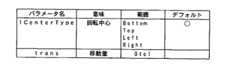
図4に、回転効果が実行される回転中心位置の一例を図示する。図4に示すように回転中心(ICenterType)は、LB(Left Bottom ),RB(Right Bottom), LT(Left Top ),R(Right Top),B(Bottom),T(Top),L(Left),R(Right)の8箇所のいずれかを設定可能である。また、画像の回転方向も時計回り(Clockwise)、反時計回り(Counterclockwise)のいずれかを設定可能となっている。これらの値は、図5に記載するようにリードアドレスジェネレータ3に供給されるパラメータである。
【0046】
リードアドレスジェネレータ3に供給される他のパラメータとして、transがある。パラメータ、transは、回転させる画像の移動量を与える時間の要素を含んだパラメータであり、パラメータ値が0である場合、全く移動をせず、パラメータ値が1である場合、画面上から消えることになる。
【0047】
具体的には、trans=(処理の開始フレームからの経過フレーム)/(処理する総フレーム)というように定義される。例えば、30フレーム分の時間で、画像Aから画像Bに切り替えたい、という場合には、リードアドレスジェネレータ3は、trans=0/30,1/30,2/30,・・・29/30,30/30という値を順に受け取り、1フレーム単位で処理をすることになる。
【0048】
リードアドレスジェネレータ3にシーケンシャルなリードアドレス(x、y)が指定されると、フレームバッファ2から読み出される画像データのアドレス(X,Y)は、以下に示す工程を経て変換され求められる。
【0049】
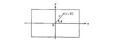
まず、リードアドレス(x,y)に対応した、アドレス(X,Y)を求める際、中心点(cx,cy)での回転を考えるより、原点中心として回転を考える方が容易である。そこで、(1−1)式を用いて、図6に示すようにリードアドレス(x,y)を原点中心としたアドレス(x0,y0)に変換する。
【0050】
【数27】
続いて、(1−2)式を用いて直交座標系を極座標系に変換する。
【0052】
【数28】
これにより、アドレス(x0,y0)は、図7に示すようにアドレス(r,θ)に変換される。
【0054】
続いて、(1−3)式によって、アドレス(r,θ)は回転され、図8に示すように回転された後のアドレス(R,Θ)が算出される。
【0055】
【数29】
なお、(1−3)式中の関数f1(θ)は、(1−4)式で示される。
【0057】
【数30】
(1−4)式で用いられている定数C1,C2は、図5に示したパラメータによって、(1−5)、(1−6)式のよう決定される。(1−5)式で示した定数C1は、回転中心が画像の四隅にある場合は90度(π/2[rad])回転させれば画面上から画像が消え、回転中心が外縁上にある場合は180(π[rad])度回転させれば画面上から画像が消えることに対応している。
【0059】
続いて、回転されて得られたアドレス(R,Θ)を極座標系から(1−7)式を用いて直行座標系のアドレス(X0,Y0)へと変換する。
【0060】
【数31】
さらに、アドレス(X0,Y0)は、直行座標系において、原点を中心に回転した結果得られたアドレスであるため、(1−8)式を用いて、中心点(cx,cy)を中心に回転したアドレス(X,Y)を求める。
【0062】
【数32】
このように、リードアドレスジェネレータ3は、リードアドレス(x,y)から、フレームバッファ2に格納されている画像データのアドレス(X,Y)へと変換する。
【0064】
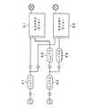
次に図9を用いて、回転効果を実行する場合のリードアドレスジェネレータ3のハードウェア構成について説明をする。
【0065】
リードアドレスジェネレータ3は、加算・乗算器、極座標→直交座標変換器などのモジュールを備えており、このモジュールの組み合わせにより、上述した演算を実行することになる。
【0066】
回転効果を実行する場合には、図9に示すように、リードアドレスジェネレータ3のADAMX(Over)31と、ADAMY(Over)33と、ADAM(Ch1)35と、座標変換器51とが用いられる。
【0067】
ADAMX(Over)31、ADAMY(Over)33、ADAM(Ch1)35は、A,B,C,D,E,F,Gという端子を備えており、この端子から入力された値に対して、(A+B)×(C+D)+E+F+Gという演算を施すことで加算・乗算を実行する。A〜Gの端子には、定数、又は、図中にダイヤマークで示したクロスポイントを指定することができる。
【0068】
座標変換器51は、極座標系から直交座標系へと変換する座標変換器である。
【0069】
次に、上述した構成のリードアドレスジェネレータ3によって、リードアドレス(x、y)からアドレス(X,Y)へ変換される動作について説明をする。なお、リードアドレス(x,y)は、前処理として(1−1)、(1−2)式に示す計算が行列計算によって実行されており、リードアドレスジェネレータ3には、極座標に変換されたアドレス(r,θ)が入力されるものとする。
【0070】
ADAM(Ch1)35は、アドレスθが入力され、θと、定数との和をとり、(1−4)式を実行し、関数f1(θ)を求める。関数f1(θ)は、アドレスrと共に、座標変換器51に供給される。関数f1(θ)及びアドレスrは、(1−3)式よりアドレス(R,Θ)である。
【0071】
座標変換器51は、アドレス(R,Θ)を直交座標に変換して、アドレス(X0,Y0)を算出する。
【0072】
ADAMX(Over)31は、RcosΘにcxを加算することで、(1−8)を実行し、アドレスXを算出する。
【0073】
ADAMY(Over)33は、RsinΘにcyを加算することで、(1−8)を実行し、アドレスYを算出する。
【0074】
このように、画像特殊効果装置1は、リードアドレスジェネレータ3を構成するハードウェアを適切に組み合わせて用いることで、リードアドレスジェネレータ3に入力されるリードアドレス(x,y)を、フレームバッファ2に格納された画像に回転効果が施された画像として出力させるように読み出すためのアドレス(X,Y)に変換することができる。
【0075】
2.分割回転効果
分割回転効果は、図10に示すように表示された画像の外縁に与えられた任意の点を回転中心として、画像が2つに裂けるように分割されて回転し、フレームバッファ4から読み出される背景画像を出現させるといった特殊効果である。画像が2つに裂けるように分割されて回転することからも分かるように、それぞれの画像は、時計回り、反時計回りに回転することになる。
【0076】
図11に分割回転効果が実行される回転中心位置の一例を図示する。図11に示すように回転中心(ICenterType)は、B(Bottom),T(Top),L(Left),R(Right)の4箇所のいずれかを設定可能である。回転中心がTop又はBottomの場合、画像は、回転中心を通る点線aで分割され、それぞれ矢印方向に回転をする。回転中心がLeft又はRightの場合、画像は、回転中心を通る点線bで分割され、それぞれ矢印方向に回転する。これらの回転中心は、図12に記載するようにリードアドレスジェネレータ3に供給されるパラメータである。
【0077】
リードアドレスジェネレータ3に供給される他のパラメータとして、transがある。パラメータ、transは、回転させる画像の移動量を与える時間の要素を含んだパラメータであり、パラメータ値が0である場合、全く移動をせず、パラメータ値が1である場合、画面上から消えることになる。
【0078】
具体的には、trans=(処理の開始フレームからの経過フレーム)/(処理する総フレーム)というように定義される。例えば、30フレーム分の時間で、画像Aから画像Bに切り替えたい、という場合には、リードアドレスジェネレータ3は、trans=0/30,1/30,2/30,・・・29/30,30/30という値を順に受け取り、1フレーム単位で処理をすることになる。
【0079】
リードアドレスジェネレータ3に、シーケンシャルなリードアドレス(x,y)が指定されると、フレームバッファ2から読み出される画像データのアドレス(X,Y)は、以下に示す工程を経て変換され求められる。
【0080】
まず、リードアドレス(x,y)に対応した、アドレス(X,Y)を求める際、中心点(cx,cy)での回転を考えるより、原点中心として回転を考える方が容易である。そこで、(2−1)式を用いて、図13に示すようにリードアドレス(x,y)を原点中心としたアドレス(x0,y0)に変換する。
【0081】
【数33】
続いて、(2−2)式を用いて直交座標系を極座標系に変換する。
【0083】
【数34】
これにより、アドレス(x0,y0)は、図14に示すようにアドレス(r,θ)に変換される。
【0085】
続いて、回転中心がBottomにある場合、(2−3)式によって、アドレス(r,θ)は回転され、図15に示すように回転された後のアドレス(R,Θ)が算出される。
【0086】
【数35】
なお、(2−3)式中の関数f1(θ)は、(2−4)式で示される。
【0088】
【数36】
続いて、回転されて得られたアドレス(R,Θ)を極座標系から(2−5)式を用いて直行座標系のアドレス(X0,Y0)へと変換する。
【0090】
【数37】
さらに、アドレス(X0,Y0)は、直行座標系において、原点を中心に回転した結果得られたアドレスであるため、(2−6)式を用いて、中心点(cx,cy)を中心に回転したアドレス(X,Y)を求める。
【0092】
【数38】
このように、リードアドレスジェネレータ3は、リードアドレス(x,y)から、フレームバッファ2に格納されている画像データのアドレス(X,Y)へと変換する。
【0094】
なお、回転中心が、Topの場合は、Θを求めるのに(2−7)式が使用される。
【0095】
【数39】
また、回転中心が、Leftの場合は、Θを求めるのに(2−8)式が使用される。
【0097】
【数40】
さらにまた、回転中心が、Rightの場合は、Θを求めるのに(2−9)式が使用される。
【0099】
【数41】
次に、図16を用いて、分割回転効果を実行する場合のリードアドレスジェネレータ3のハードウェア構成について説明をする。
【0101】
リードアドレスジェネレータ3は、加算・乗算器、極座標→直交座標変換器などのモジュールを備えており、このモジュールの組み合わせにより、上述した演算を実行することになる。
【0102】
分割回転効果効果を実行する場合には、図16に示すように、リードアドレスジェネレータ3のLUT(Look Up Table)43と、ADAMX(Over)31と、ADAMY(Over)33と、ADAM(Ch1)35と、ADAM(Ch2)36と、座標変換器51とが用いられる。
【0103】
LUT43は、図中にダイヤマークで示したクロスポイントで指定されたアドレスによって参照されるRAM(Random Access Memory)テーブルであり、このデータは、図示しないCPU(Central Processing Unit)によって設定される。LUT43には、図示しないCPUによって関数f1(θ)が設定されている。
【0104】
ADAMX(Over)31、ADAMY(Over)33、ADAM(Ch1)35、ADAM(Ch2)36は、A,B,C,D,E,F,Gという端子を備えており、この端子から入力された値に対して、(A+B)×(C+D)+E+F+Gという演算を施すことで加算・乗算を実行する。A〜Gの端子には、定数、又は、図中にダイヤマークで示したクロスポイントを指定することができる。
【0105】
座標変換器51は、極座標系から直交座標系へと変換する座標変換器である。
【0106】
次に、上述した構成のリードアドレスジェネレータ3によって、リードアドレス(x,y)からアドレス(X,Y)へ変換される動作について説明をする。なお、リードアドレス(x,y)は、前処理として(2−1)、(2−2)式に示す計算が行列計算によって実行されており、リードアドレスジェネレータ3には、極座標に変換されたアドレス(r,θ)が入力されるものとする。
【0107】
ADAM(Ch2)36は、アドレスθからICenterTypeに応じて0、π、−π/2、π/2のいずれかを減算し、LUT43に供給する。
【0108】
ADAM(Ch1)35は、LUT43からの出力に上述したICenterTypeに応じて0、π、−π/2、π/2を加算して(2−3)、(2−7)、(2−8)、又は(2−9)式を実行する。
【0109】
座標変換器51は、アドレスrと、ADAM(Ch1)35の出力が、アドレス(R,Θ)であることから、(2−5)式を実行し、座標変換してアドレス(X0,Y0)=(RcosΘ,RsinΘ)を算出する。RcosΘ、RsinΘは、それぞれ、ADAMX(Over)31、ADAMY(Over)33に供給される。
【0110】
ADAMX(Over)31は、座標変換器51から供給されるRcosΘにcxを加算することで、(2−6)式を実行し、アドレスXを算出する。
【0111】
ADAMY(Over)33は、座標変換器51から供給されるRsinΘにcyを加算することで(2−6)式を実行し、アドレスYを算出する。
【0112】
このように、画像特殊効果装置1は、リードアドレスジェネレータ3を構成するハードウェアを適切に組み合わせて用いることで、リードアドレスジェネレータ3に入力されるリードアドレス(x,y)を、フレームバッファ2に格納された画像に分割回転効果が施された画像として出力させるように読み出すためのアドレス(X,Y)に変換することができる。
【0113】
3.分割移動効果
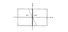
分割移動効果は、図17に示すように画像を分割し、分割した画像をx軸方向及び/又はy軸方向に平行移動させ、フレームバッファ4から読み出される背景画像を出現させるといった特殊効果である。
【0114】
分割移動効果では、図18に示すように、画像を垂直方向に2つに分割し、分割した画像を矢印で示すx軸方向に平行移動させる場合(Vertical)と、図19に示すように、画像を水平方向に分割し、分割した画像を矢印で示すy軸方向に平行移動させる場合(Horizontal)と、図20に示すように画像を水平、垂直方向に4分割してそれぞれ矢印で示すx軸方向及びy軸方向に平行移動させる場合(Cross)とがある。図18,19,20に示す画像を分割する線は、図中に点線で示すようにある傾きを持たせることもできる。
【0115】
図21に、分割移動効果を実行する際に、リードアドレスジェネレータ3に供給されるパラメータを示す。上述した、画像を分割するタイプは、IBarnTypeとして記載されている。デフォルトは、Verticalである。パラメータfixSlantによって、画像を分割する際の分割線の傾きが−45度〜45度のように設定することができる。
【0116】
さらに、パラメータ、transによって、分割された画像の移動量を設定することができる。パラメータ、transの値を0に設定すれば、分割された画像は、全く移動せず、またtransの値を1に設定すれば画面上から完全に消えることになる。
【0117】
transは、時間の要素を含んだパラメータであり、具体的には、trans=(処理の開始フレームからの経過フレーム)/(処理する総フレーム)というように定義される。例えば、30フレーム分の時間で、画像Aから画像Bに切り替えたい、という場合には、リードアドレスジェネレータ3は、trans=0/30,1/30,2/30,・・・29/30,30/30という値を順に受け取り、1フレーム単位で処理をすることになる。
【0118】
リードアドレスジェネレータ3にシーケンシャルなリードアドレス(x,y)が指定されると、フレームバッファ2から読み出される画像データのアドレス(X,Y)は、以下に示す工程を経て変換され求められる。
【0119】
まず、(3−1)式を用いて、分割した画像を移動させる際の中心を原点とするための変換を行い、リードアドレス(x,y)をアドレス(x0,y0)とする。
【0120】
【数42】
続いて、IBarnTypeが、Verticalの場合は、(3−2)式を用いて、垂直方向に画像を2分割してx軸方向に移動させる。
【0122】
【数43】
なお、(3−2)式中の関数f1(y0)、f2(t)は、それぞれ、(3−3)、(3−4)式に示される。
【0124】
【数44】
(3−4)式中のMaxは、アドレス(X0,Y0)で指定できる画像以外のアドレスを指定していることを表している。例えば、Maxが、フレームバッファ2に記憶された青色の画像が記憶されたアドレスを指定しているとすると、上記画像をキー信号として他の画像を、上記Maxとなった領域に容易に合成させることができる。
【0126】
さらに、アドレス(X0,Y0)は、中心位置の移動をしているので、(3−5)式を用いて、アドレス(X,Y)を求める。
【0127】
【数45】
このように、リードアドレスジェネレータ3は、リードアドレス(x,y)から、フレームバッファ2に格納されている画像データのアドレス(X,Y)へと変換する。
【0129】
また、IBarnTypeがHorizontalの場合は、(3−6)式を用いて、水平方向に画像を2分割してy軸方向に移動させる。
【0130】
【数46】
なお、(3−6)式中の関数f1(x0)、f2(t)は、それぞれ、(3−7)、(3−8)式に示される。
【0132】
【数47】
さらにまた、IBarnTypeがcrossの場合は、(3−9)式を用いて、垂直方向、水平方向に画像を4分割して、x軸方向、y軸方向に移動させる。
【0134】
【数48】
なお、(3−9)式中の関数f1(y0)、f2(x0)、f3(t)は、それぞれ、(3−10)、(3−11)、(3−12)式に示される。
【0136】
【数49】
また、(3−8)、(3−12)式中のMaxは、アドレス(X0,Y0)で指定できる画像以外のアドレスを指定していることを表している。例えば、Maxが、フレームバッファ2に記憶された青色の画像が記憶されたアドレスを指定しているとすると、上記画像をキー信号として他の画像を、上記Maxとなった領域に容易に合成させることができる。
【0138】
次に、図22,23を用いて、分割移動効果を実行する場合のリードアドレスジェネレータ3のハードウェア構成について説明をする。
【0139】
分割移動効果を実行する場合、リードアドレスジェネレータ3のハードウェア構成は、分割の種別であるIBarnTypeの違いによって構成が異なっている。
【0140】
まず、IBarnTypeがVerticalの場合について説明をする。
【0141】
リードアドレスジェネレータ3は、加算・乗算器、極座標→直交座標変換器などのモジュールを備えており、このモジュールの組み合わせにより、上述した演算を実行することになる。
【0142】
分割移動効果(IBarnType=Vertical)を実行する場合には、図22に示すように、リードアドレスジェネレータ3のLUT(Look Up Table)41,42,43,44と、ADAMX(Over)31と、ADAMY(Over)33と、ADAM(Ch1)35と、ADAM(Ch2)36とが用いられる。
【0143】
LUT41,42,43,44は、図中にダイヤマークで示したクロスポイントで指定されたアドレスによって参照されるRAM(Random Access Memory)テーブルであり、このデータは、図示しないCPU(Central Processing Unit)によって設定される。LUT41,43,44には、それぞれ、(3−4)式に示す関数f2(t)、y×(−tanθ)、x×tanθが設定されている。LUT42は、ADAM(Ch2)36の値をスルーして出力する設定となっている。
【0144】
ADAMX(Over)31、ADAMY(Over)33、ADAM(Over)35、ADAM(Ch2)36は、A,B,C,D,E,F,Gという端子を備えており、この端子から入力された値に対して、(A+B)×(C+D)+E+F+Gという演算を施すことで加算・乗算を実行する。A〜Gの端子には、定数、又は、図中にダイヤマークで示したクロスポイントを指定することができる。
【0145】
次に、上述した構成のリードアドレスジェネレータ3によって、リードアドレス(x,y)からアドレス(X,Y)へ変換される動作について説明をする。なお、リードアドレス(x,y)は、前処理として(3−1)式に示す計算が行列計算によって実行されており、リードアドレスジェネレータ3には、変換されたアドレス(x0,y0)が入力されるものとする。
【0146】
ADAM(Ch1)35は、LUT43から供給されるy0×(−tanθ)をx0から加算してLUT41に出力する。LUT41は、ADAM(Ch1)35からの出力を関数f2(t)に入力し、ADAMX(Over)31に供給する。ADAMX(Over)31は、LUT41からの出力と、LUT43からの出力とを減算して、(3−2)式に示すアドレスX0を算出する。
【0147】
ADAM(Ch2)36は、LUT44から供給されるx0×(tanθ)をy0から減算してLUT42に出力する。LUT42は、ADAM(Ch2)36からの出力をそのまま、ADAMY(Over)33に供給する。ADAMY(Over)33は、LUT42からの出力と、LUT44からの出力とを加算して、(3−2)式に示すアドレスY0を算出する。
【0148】
続いて、IBarnTypeがHorizontalの場合について説明をする。IBarnTypeがHorizontal である場合、IBarnTypeがVerticalである場合と同様に、リードアドレスジェネレータ3の構成は、図22のようになる。
【0149】
ただし、LUT42に関数f2(t)が設定され、LUT41は、ADAM(Ch1)35の値をスルーして出力する設定となる。
【0150】
ADAM(Ch1)35は、LUT43から供給されるy0×(−tanθ)をx0から減算してLUT41に出力する。LUT41は、ADAM(Ch1)35からの出力をそのまま、ADAMX(Over)31に供給する。ADAMX(Over)31は、LUT41からの出力と、LUT43からの出力とを加算して、(3−6)式に示すアドレスX0を算出する。
【0151】
ADAM(Ch2)36は、LUT44から供給されるx0×(tanθ)をy0から減算してLUT42に出力する。LUT42は、ADAM(Ch2)36からの出力を関数f2(t)に入力し、ADAMY(Over)33に供給する。ADAMY(Over)33は、LUT42からの出力と、LUT44からの出力とを加算して、(3−6)式に示すアドレスY0を算出する。
【0152】
続いて、IBarnTypeがCrossの場合について説明をする。
【0153】
分割移動効果(IBarnType=Cross)を実行する場合には、図23に示すように、リードアドレスジェネレータ3のLUT(Look Up Table)41,42,43,44と、ADAMX(Over)31と、ADAMY(Over)33とが用いられる。
【0154】
LUT41,42には、それぞれ(3−10)式に示す関数f1(y0)、(3−11)式に示す関数f2(x0)が設定されている。また、LUT43,44にはそれぞれ、LUT42からの出力にcosθを乗算する設定、LUT42からの出力にsinθを乗算する設定がなされている。
【0155】
ADAMX(Over)31は、LUT41からの出力にcosθを乗算し、さらにLUT43からの出力を加算してアドレスX0を算出する。
【0156】
ADAMY(Over)33は、LUT41からの出力に(−sinθ)を乗算し、さらにLUT44からの出力を加算してアドレスY0を算出する。
【0157】
このように、画像特殊効果装置1は、リードアドレスジェネレータ3を構成するハードウェアを適切に組み合わせて用いることで、リードアドレスジェネレータ3に入力されるリードアドレス(x,y)を、フレームバッファ2に格納された画像に分割移動効果が施された画像として出力させるように読み出すためのアドレス(X,Y)に変換することができる。
【0158】
このように、画像特殊効果装置1は、リードアドレスジェネレータ3を構成するハードウェアを適切に組み合わせて用いることで、リードアドレスジェネレータ3に入力されるリードアドレス(x,y)を、フレームバッファ2に格納された画像に分割移動効果が施された画像として出力させるように読み出すためのアドレス(X,Y)に変換することができる。
【0159】
4.引き破り効果
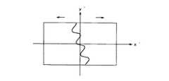
引き破り効果は、図24に示すように、直線ではない切断面で画像を垂直に2分割し、分割した画像をx軸方向に移動させ、フレームバッファ4から読み出される背景画像を出現させるといった特殊効果である。引き破り効果では、紙などを左右に引っ張って破ったときのような効果を出すことができる。
【0160】
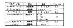
引き破り効果における、切断面の形状は、図25に示すように関数F(x)によって与えられる。関数F(x)は、リードアドレスジェネレータ3に供給される図26に示すパラメータのfixAmplitudeで最大振幅、fixFrequencyで周波数、fixPhaseで位相が与えられ、さらに、一定の間隔で[−1.0,1.0]の乱数を発生させ、補間タイプ(lInterpolationType)に応じた方法で補間することで生成される。
【0161】
図27,28,29に、それぞれ、補間タイプの異なるNear、Linear、Lagrangeによって生成される関数F(x)の一例を示す。
【0162】
また、引き破り効果では、図30に示すように、座標軸をφだけ回転させることで、座標変換し、図31に示すように切断面の波形に傾きを持たせることもできる。
【0163】
リードアドレスジェネレータ3に供給される他のパラメータとして、transがある。パラメータ、transは、回転させる画像の移動量を与える時間の要素を含んだパラメータであり、パラメータ値が0である場合、全く移動をせず、パラメータ値が1である場合、画面上から消えることになる。
【0164】
具体的には、trans=(処理の開始フレームからの経過フレーム)/(処理する総フレーム)というように定義される。例えば、30フレーム分の時間で、画像Aから画像Bに切り替えたい、という場合には、リードアドレスジェネレータ3は、trans=0/30,1/30,2/30,・・・29/30,30/30という値を順に受け取り、1フレーム単位で処理をすることになる。
【0165】
リードアドレスジェネレータ3に、シーケンシャルなリードアドレス(x、y)が指定されると、フレームバッファ2から読み出される画像データのアドレス(X,Y)は、以下に示す工程を経て変換され求められる。
【0166】
まず、リードアドレス(x,y)に対応したアドレス(X,Y)を求める際、フレームバッファ2に格納された画像データの座標系から、計算上への座標系へと変換するため、(4−1)式を用いて、リードアドレスをアドレス(x0,y0)に変換する。
【0167】
【数50】
続いて、(4−2)式を用いて、座標をφだけ回転させて座標変換を行う。
【0169】
【数51】
アドレス(x0,y0)がφだけ回転されることで、アドレス(x1,y1)に変換される。
【0171】
次に、(4−3)式を用いて、関数F(x)が形成する波形を断面形状として、画像を2分割してx軸方向に移動させる。
【0172】
【数52】
なお、(4−3)式中の関数f1(y1)、f2(t)は、それぞれ(4−4)、(4−5)式に示される。
【0174】
【数53】
(4−5)式中のMaxは、アドレス(X0,Y0)で指定できる画像以外のアドレスを指定していることを表している。例えば、Maxが、フレームバッファ2に記憶された青色の画像が記憶されたアドレスを指定しているとすると、上記画像をキー信号として他の画像を、上記Maxとなった領域に容易に合成させることができる。
【0176】
断面の波形を形成する関数F(x)は、(4−4)式中にF((y1−fixPhase)×fixFreqency)として示されている。
【0177】
続いて、算出されたアドレス(X1,Y1)に対して、(4−6)式を用いて、(4−2)式とは逆方向にφだけ回転させて座標変換をし、アドレス(X0,Y0)を求める。
【0178】
【数54】
さらに、アドレス(X0,Y0)は、中心位置の移動をしているので、(4−7)式を用いて、アドレス(X,Y)を求める。
【0180】
【数55】
このように、リードアドレスジェネレータ3は、リードアドレス(x,y)からフレームバッファ2に格納されている画像データのアドレス(X,Y)へと変換する。
【0182】
次に、図32を用いて、引き破り効果を実行する場合のリードアドレスジェネレータ3のハードウェア構成について説明をする。
【0183】
リードアドレスジェネレータ3は、加算・乗算器、極座標→直交座標変換器などのモジュールを備えており、このモジュールの組み合わせにより、上述した演算を実行することになる。
【0184】
引き破り効果を実行する場合には、図32に示すように、リードアドレスジェネレータ3のLUT(Look Up Table)41,42,43,44と、ADAMX(Over)31と、ADAMY(Over)33と、ADAM(Ch1)35と、ADAM(Ch2)36とが用いられる。
【0185】
LUT41,42,43,44は、図中にダイヤマークで示したクロスポイントで指定されたアドレスによって参照されるRAM(Random Access Memory)テーブルであり、このデータは、図示しないCPU(Central Processing Unit)によって設定される。LUT41,42,43,44には、図示しないCPUによってそれぞれ、a×sinφ、a×cosφ、関数f1(a)、関数f2(t)が設定されている。なお、aは、LUT41,42に入力される値を示している。
【0186】
ADAMX(Over)31、ADAMX(Under)32、ADAMY(Over)33、ADAMY(Ch1)35、ADAM(Ch2)36は、A,B,C,D,E,F,Gという端子を備えており、この端子から入力された値に対して、(A+B)×(C+D)+E+F+Gという演算を施すことで加算・乗算を実行する。A〜Gの端子には、定数、又は、図中にダイヤマークで示したクロスポイントを指定することができる。
【0187】
次に、上述した構成のリードアドレスジェネレータ3によって、リードアドレス(x,y)からアドレス(X,Y)へ変換される動作について説明をする。なお、リードアドレス(x,y)は、前処理として(4−1)、(4−2)式に示す計算が行列計算によって実行されており、リードアドレスジェネレータ3には、座標変換されたアドレス(x1,y1)が入力されるものとする。
【0188】
ADAM(Ch1)35は、アドレスx1と、LUT43からの出力とによって、t=x1−f1(y1)を実行する。この値はLUT44で、f2(t)に入力される。
【0189】
ADAM(Ch2)36は、LUT43からの出力f1(y1)と、LUT44からの出力f2(x1−f1(y1))とを加算して、(4−3)式を実行し、X1を算出する。
【0190】
ADAMX(Over)31は、ADAM(Ch2)36からの出力であるX1にCosφを乗算し、さらに、LUT41からの出力であるy1×sinφを減算して、(4−6)式を実行することでアドレスX0を算出する。さらにcxを加算することで、(4−7)式を実行し、アドレスXを算出する。
【0191】
ADAMY(Over)33は、ADAM(Ch2)36からの出力であるX1にsinφを乗算し、さらに、LUT42からの出力であるy1×cosφを加算して、(4−6)式を実行することでアドレスY0を算出する。さらにcyを加算することで、(4−7)式を実行し、アドレスYを算出する。
【0192】
このように、画像特殊効果装置1は、リードアドレスジェネレータ3を構成するハードウェアを適切に組み合わせて用いることで、リードアドレスジェネレータ3に入力されるリードアドレス(x,y)を、フレームバッファ2に格納された画像に引き破り効果が施された画像として出力させるように読み出すためのアドレス(X,Y)に変換することができる。
【0193】
5.跳ね返り効果
跳ね返り効果は図33に示すように、フレームバッファ4から読み出され表示されている背景画像上に、新たな画像が表示領域の外側から飛び込むように出現し、出現側と対向する側の表示領域外縁で所定の回数だけ跳ね返りながら表示領域の中央まで移動して、挿入されるといった特殊効果である。
【0194】
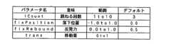
図34を用いて、跳ね返り効果において、リードアドレスジェネレータ3に入力されるパラメータについて説明をする。
【0195】
ICountは、画像が跳ね返る回数を設定するパラメータであり、1〜10回まで設定可能である。デフォルト値は、3となっている。
【0196】
fixPositionは、落下位置を指定するパラメータである。fixPositionのパラメータ値が、−1.0の場合は、図35に示すように画像の左端が落下位置となり、1.0の場合は、画像の右端が落下位置となり、0の場合は、画像の中央が落下位置となる。落下した画像は、ICountで設定された跳ね返り回数だけ跳ね返ると、中央位置までx軸方向に移動して停止することになる。
【0197】
fixReboundは、反発力であり、パラメータ値が0の場合は、全く跳ね返らず、パラメータ値が1.0の場合、画像は、画面の下で跳ね返り、画面上から消える動作となる。
【0198】
リードアドレスジェネレータ3に供給される他のパラメータとして、transがある。パラメータ、transは、回転させる画像の移動量を与える時間の要素を含んだパラメータであり、パラメータ値が0である場合、全く移動をせず、パラメータ値が1である場合、画面上から消えることになる。
【0199】
具体的には、trans=(処理の開始フレームからの経過フレーム)/(処理する総フレーム)というように定義される。例えば、30フレーム分の時間で、画像Aから画像Bに切り替えたい、という場合には、リードアドレスジェネレータ3は、trans=0/30,1/30,2/30,・・・29/30,30/30という値を順に受け取り、1フレーム単位で処理をすることになる。
【0200】
リードアドレスジェネレータ3に、シーケンシャルなリードアドレス(x、y)が指定されると、フレームバッファ2から読み出される画像データのアドレス(X,Y)は、以下に示す工程を経て変換され求められる。
【0201】
跳ね返り効果において、リードアドレスジェネレータ3に入力されたリードアドレス(x、y)は、(5−1)式を用いて、アドレス(X,Y)に変換される。
【0202】
【数56】
なお、(5−1)式中の関数f1(x)、f2(y)は、それぞれ(5−2)、(5−3)式で示される。
【0204】
【数57】
(5−2)式より、fixPositionが負である場合、例えば−1.0などは、x軸に沿って正方向に移動し、fixPositionが正である場合、例えば1.0などは、x軸に沿って負方向に移動するのが分かる。また、fixPositionが0の場合は、リードアドレスxは、アドレスXに変換され、全く移動しないことが分かる。
【0206】
(5−3)式は、跳ね返る画像の高さ位置を示している。(5−3)式による軌跡を具体的に示すと図36のようになる。これは、跳ね返る回数を与えるパラメータlCountがデフォルト値3、反発力を与えるfixReboundがデフォルト値0.5である場合の(5−3)式の軌跡である。高さHから落下された画像は、跳ね返る毎に高さを半分に減衰させながら、3回跳ね返っているのが分かる。
【0207】
このように、リードアドレスジェネレータ3は、リードアドレス(x,y)から、フレームバッファ2に格納されている画像データのアドレス(X,Y)へと変換する。
【0208】
次に、図37を用いて、跳ね返り効果を実行する場合のリードアドレスジェネレータ3のハードウェア構成について説明をする。
【0209】
リードアドレスジェネレータ3は、加算・乗算器、極座標→直交座標変換器などのモジュールを備えており、このモジュールの組み合わせにより、上述した演算を実行することになる。
【0210】
跳ね返り効果を実行する場合には、図37に示すように、リードアドレスジェネレータ3のADAMX(Over)31と、ADAMY(Over)33とが用いられる。
【0211】
ADAMX(Over)31、ADAMY(Over)33は、A,B,C,D,E,F,Gという端子を備えており、この端子から入力された値に対して、(A+B)×(C+D)+E+F+Gという演算を施すことで加算・乗算を実行する。A〜Gの端子には、定数、又は、図中にダイヤマークで示したクロスポイントを指定することができる。
【0212】
次に、上述した構成のリードアドレスジェネレータ3によって、リードアドレス(x,y)からアドレス(X,Y)へ変換される動作について説明をする。
【0213】
ADAMX(Over)31は、入力されたアドレスxに対して、(5−2)に示す定数を加算して、アドレスXを算出する。
【0214】
ADAMY(Over)33は、入力されたアドレスyに対して、(5−3)に示す定数を加算して、アドレスYを算出する。
【0215】
このように、画像特殊効果装置1は、リードアドレスジェネレータ3を構成するハードウェアを適切に組み合わせて用いることで、リードアドレスジェネレータ3に入力されるリードアドレス(x,y)を、フレームバッファ2に格納された画像に跳ね返り効果が施された画像として出力させるように読み出すためのアドレス(X,Y)に変換することができる。
【0216】
【発明の効果】
以上の説明からも明らかなように、本発明は、読み出しアドレス生成手段によって、フレームバッファに記憶された画像信号に対応する画像が、表示時に表示領域の外縁に与える任意の点を回転中心として回転移動し、画像が表示領域の外側に消え去るような特殊効果が得られるように、フレームバッファに記憶された画像信号の読み出しアドレスが生成されることで、全く新しい画像特殊効果を実施することを可能とする。
【0217】
以上の説明からも明らかなように、本発明は、読み出しアドレス生成手段によって、フレームバッファに記憶された画像信号に対応する画像が、表示時に直線状の境界線を有する2つの部分画像に分割され、当該境界線が表示領域の外縁とが交差することになる2つの交点のうちいずれか一方を回転中心として、互いに相反する方向に回転移動し、部分画像がそれぞれ表示領域の外側に消え去るような特殊効果が得られるように、フレームバッファに記憶された画像信号の読み出しアドレスが生成されることで、全く新しい画像特殊効果を実施することを可能とする。
【0218】
以上の説明からも明らかなように、本発明は、読み出しアドレス生成手段によって、フレームバッファに記憶された画像信号に対応する画像が、表示時に直線状の境界線を有する複数の部分画像に分割され、各部分画像がそれぞれ表示領域の外側に消え去るように平行移動するような特殊効果が得られるように、フレームバッファに記憶された画像信号の読み出しアドレスが生成されることで、全く新しい画像特殊効果を実施することを可能とする。
【0219】
以上の説明からも明らかなように、本発明は、読み出しアドレス生成手段によって、フレームバッファに記憶された画像信号に対応する画像が、表示時に所定の関数で与えられる波形の境界線を有する複数の部分画像に分割され、各部分画像がそれぞれ表示領域の外側に消え去るように平行移動するような特殊効果が得られるように、フレームバッファに記憶された画像信号の読み出しアドレスが生成されることで、全く新しい画像特殊効果を実施することを可能とする。
【0220】
以上の説明からも明らかなように、本発明は、読み出しアドレス生成手段によって、上記フレームバッファから読み出される画像信号に所望の特殊効果を与える特殊効果装置において、上記フレームバッファに記憶された画像信号に対応する画像が、表示時に表示領域の外側から飛び込むように出現して、当該画像の出現側とは反対側の表示領域外縁で跳ね返り、所定回数の跳ね返りの後、表示領域の中央まで移動するような特殊効果が得られるように、フレームバッファに記憶された画像信号の読み出しアドレスが生成されることで、全く新しい画像特殊効果を実施することを可能とする。
【図面の簡単な説明】
【図1】本発明の実施の形態として示す画像特殊効果装置の構成について説明するための図である。
【図2】同画像特殊効果装置で採用するリードアドレスコントロール方式について説明するための具体例を示した図である。
【図3】同画像特殊効果装置によって、回転効果を施した画像の一例を示した図である。
【図4】回転効果における回転中心について説明するための図である。
【図5】回転効果を実行する際にリードアドレスジェネレータに供給されるパラメータを示した図である。
【図6】回転効果における回転中心を原点に変換する様子について説明するための図である。
【図7】回転効果における極座標変換について説明するための図である。
【図8】回転効果におけるアドレス変換について説明するための図である。
【図9】回転効果を実現するリードアドレスジェネレータのハードウェア構成について説明するための図である。
【図10】同画像特殊効果装置によって、分割回転効果を施した画像の一例を示した図である。
【図11】分割回転効果における回転中心について説明するための図である。
【図12】分割回転効果を実行する際にリードアドレスジェネレータに供給されるパラメータを示した図である。
【図13】分割回転効果における回転中心を原点に変換する様子について説明するための図である。
【図14】分割回転効果における極座標変換について説明するための図である。
【図15】分割回転効果におけるアドレス変換について説明するための図である。
【図16】分割回転効果を実現するリードアドレスジェネレータのハードウェア構成について説明するための図である。
【図17】同画像特殊効果装置によって、分割移動効果を施した画像の一例を示した図である。
【図18】分割移動効果において、画像を垂直方向に分割する場合について説明するための図である。
【図19】分割移動効果において、画像を水平方向に分割する場合について説明するための図である。
【図20】分割移動効果において、画像を、垂直及び水平方向に分割する場合について説明するための図である。
【図21】分割移動効果を実行する際にリードアドレスジェネレータに供給されるパラメータを示した図である。
【図22】画像を垂直又は水平に分割して、分割回転効果を実現するリードアドレスジェネレータのハードウェア構成について説明するための図である。
【図23】画像を垂直及び水平に分割して、分割回転効果を実現するリードアドレスジェネレータのハードウェア構成について説明するための図である。
【図24】同画像特殊効果装置によって、引き破り効果を施した画像の一例を示した図である。
【図25】引き破り効果において、画像を分割する波形を示した図である。
【図26】引き破り効果を実行する際にリードアドレスジェネレータに供給されるパラメータを示した図である。
【図27】波形を作る関数の第1の補間方法について示した図である。
【図28】波形を作る関数の第2の補間方法について示した図である。
【図29】波形を作る関数の第3の補間方法について示した図である。
【図30】引き破り効果において、座標軸を回転させる場合について説明するための図である。
【図31】引き破り効果においおて、座標軸を回転させた場合に出力される画像について示した図である。
【図32】引き破り効果を実現するリードアドレスジェネレータのハードウェア構成について説明するための図である。
【図33】同画像特殊効果装置によって、跳ね返り効果を施した画像の一例を示した図である。
【図34】跳ね返り効果を実行する際にリードアドレスジェネレータに供給されるパラメータを示した図である。
【図35】跳ね返り効果において、画像を落下させる位置について説明するための図である。
【図36】跳ね返り効果において、関数f2(y)の軌跡を示した図である。
【図37】跳ね返り効果を実現するリードアドレスジェネレータのハードウェア構成について説明するための図である。
【符号の説明】
1 画像特殊効果装置、2 フレームバッファ、3 リードアドレスジェネレータ、4 フレームバッファ、5 画像合成部[0001]
TECHNICAL FIELD OF THE INVENTION
The present invention relates to a special image effect, and more particularly, to a special effect device for executing a special image effect using a read address control method.
[0002]
[Prior art]
A read address control method for applying a special image effect by converting an address at the time of reading with respect to an image signal stored in a frame buffer and reading the converted image signal has been devised and implemented (for example, see Patent Document 1).
[0003]
[Patent Document 1]
JP-A-10-145672
[0004]
[Problems to be solved by the invention]
In the above-described read address control method, only very simple image special effects such as enlargement, reduction, rotation, and movement of an image are devised and implemented.
[0005]
Therefore, an object of the present invention is to provide a special effect device, an address signal generating device, an address signal generating method, and an address signal generating program for executing a completely new image special effect using the above-described read address method. I do.
[0006]
[Means for Solving the Problems]
In order to achieve the above object, a special effect device according to the present invention reads out an image signal from a frame buffer based on an address signal, thereby providing a desired special effect to an image signal read from the frame buffer. In the device, a special effect such that an image corresponding to the image signal stored in the frame buffer rotates around an arbitrary point given to the outer edge of the display area at the time of display, and the image disappears outside the display area. And an address signal generating means for generating a read address signal of the image signal stored in the frame buffer.
[0007]
In order to achieve the above object, an address signal generation device according to the present invention is an address signal generation device for generating an address signal for reading an image signal from a frame buffer, the image signal corresponding to the image signal stored in the frame buffer. The image signal stored in the frame buffer is rotated so that a special effect such that the image disappears outside the display area can be obtained by rotating around an arbitrary point given to the outer edge of the display area at the time of display. And an address signal generating means for generating the read address signal.
[0008]
In order to achieve the above object, an address signal generating method according to the present invention is directed to an address signal generating method for generating an address signal for reading an image signal from a frame buffer, the image signal corresponding to the image signal stored in the frame buffer. The image signal stored in the frame buffer is rotated so that a special effect such that the image disappears outside the display area can be obtained by rotating around an arbitrary point given to the outer edge of the display area at the time of display. An address signal generating step of generating a read address signal of
[0009]
In order to achieve the above object, an address signal generation program according to the present invention is an address signal generation program for causing a computer to execute a step of generating an address signal for reading an image signal from a frame buffer. An image corresponding to the image signal is rotated around an arbitrary point given to the outer edge of the display area at the time of display, so that a special effect such that the image disappears outside the display area is obtained. And causing the computer to execute an address signal generating step of generating a read address signal of the stored image signal.
[0010]
In order to achieve the above object, a special effect device according to the present invention reads out an image signal from a frame buffer based on an address signal, thereby providing a desired special effect to an image signal read from the frame buffer. In the apparatus, an image corresponding to the image signal stored in the frame buffer is divided into two partial images having a linear boundary when displayed, and the boundary intersects the outer edge of the display area. The image is stored in the frame buffer so that a special effect such that the partial image disappears outside the display area can be obtained by rotating about one of the two intersections in the direction opposite to each other and rotating the image in the opposite direction. An address signal generating means for generating a read address signal of the image signal is provided.
[0011]
In order to achieve the above object, an address signal generation device according to the present invention is an address signal generation device for generating an address signal for reading an image signal from a frame buffer, the image signal corresponding to the image signal stored in the frame buffer. Are divided into two partial images having a linear boundary line at the time of display, and the boundary line conflicts with one of two intersections at which the outer edge of the display area intersects with the center of rotation. Address signal generating means for generating a read address signal of the image signal stored in the frame buffer so as to obtain a special effect of rotating in the direction and erasing the partial images outside the display area. It is characterized by the following.
[0012]
In order to achieve the above object, an address signal generating method according to the present invention is directed to an address signal generating method for generating an address signal for reading an image signal from a frame buffer, the image signal corresponding to the image signal stored in the frame buffer. Are divided into two partial images having a linear boundary line at the time of display, and the boundary line conflicts with one of two intersections at which the outer edge of the display area intersects with the center of rotation. An address signal generating step of generating a read address signal of the image signal stored in the frame buffer so that a special effect such that the partial image disappears outside the display area by rotating in the direction is obtained. It is characterized by the following.
[0013]
In order to achieve the above object, an address signal generation program according to the present invention is an address signal generation program for causing a computer to execute a step of generating an address signal for reading an image signal from a frame buffer. An image corresponding to the image signal is divided into two partial images having a linear boundary at the time of display, and one of two intersections at which the boundary intersects the outer edge of the display area is rotated. As a center, a read address signal of the image signal stored in the frame buffer is generated so that a special effect is obtained in which the partial images are rotated in directions opposite to each other and the partial images disappear outside the display area, respectively. The computer is caused to execute an address signal generation step.
[0014]
In order to achieve the above object, a special effect device according to the present invention reads out an image signal from a frame buffer based on an address signal, thereby providing a desired special effect to an image signal read from the frame buffer. In the apparatus, an image corresponding to the image signal stored in the frame buffer is divided into a plurality of partial images having a linear boundary at the time of display, and each of the partial images is translated so as to disappear outside the display area. And an address signal generating means for generating a read address signal of the image signal stored in the frame buffer so as to obtain a special effect as described above.
[0015]
In order to achieve the above object, an address signal generation device according to the present invention is an address signal generation device for generating an address signal for reading an image signal from a frame buffer, the image signal corresponding to the image signal stored in the frame buffer. Is divided into a plurality of partial images having a linear boundary line at the time of display, and stored in the frame buffer so that a special effect such that each partial image is moved in parallel so as to disappear outside the display area can be obtained. Address signal generating means for generating a read address signal of the image signal.
[0016]
In order to achieve the above object, an address signal generating method according to the present invention is directed to an address signal generating method for generating an address signal for reading an image signal from a frame buffer, the image signal corresponding to the image signal stored in the frame buffer. Is divided into a plurality of partial images having a linear boundary line at the time of display, and stored in the frame buffer so that a special effect such that each partial image is moved in parallel so as to disappear outside the display area can be obtained. An address signal generating step of generating a read address signal of the image signal.
[0017]
In order to achieve the above object, an address signal generation program according to the present invention is an address signal generation program for causing a computer to execute a step of generating an address signal for reading an image signal from a frame buffer. The image corresponding to the image signal is divided into a plurality of partial images having a linear boundary at the time of display, and a special effect is obtained such that each partial image moves in parallel so as to disappear outside the display area. And causing the computer to execute an address signal generating step of generating a read address signal of the image signal stored in the frame buffer.
[0018]
In order to achieve the above object, a special effect device according to the present invention reads out an image signal from a frame buffer based on an address signal, thereby providing a desired special effect to an image signal read from the frame buffer. In the device, the image corresponding to the image signal stored in the frame buffer is divided into a plurality of partial images having a waveform boundary line given by a predetermined function at the time of display, and each partial image is outside the display area. An address signal generating means for generating a read address signal of the image signal stored in the frame buffer so as to obtain a special effect such as a parallel movement so as to disappear is provided.
[0019]
In order to achieve the above object, an address signal generation device according to the present invention is an address signal generation device for generating an address signal for reading an image signal from a frame buffer, the image signal corresponding to the image signal stored in the frame buffer. Is divided into a plurality of partial images having a boundary of a waveform given by a predetermined function at the time of display, so that a special effect such that each partial image is moved in parallel so as to disappear outside the display area is obtained. An address signal generating means for generating a read address signal of the image signal stored in the frame buffer is provided.
[0020]
In order to achieve the above object, an address signal generating method according to the present invention is directed to an address signal generating method for generating an address signal for reading an image signal from a frame buffer, the image signal corresponding to the image signal stored in the frame buffer. Is divided into a plurality of partial images having a boundary of a waveform given by a predetermined function at the time of display, so that a special effect such that each partial image is moved in parallel so as to disappear outside the display area is obtained. An address signal generating step of generating a read address signal of the image signal stored in the frame buffer.
[0021]
In order to achieve the above object, an address signal generation program according to the present invention is an address signal generation program for causing a computer to execute a step of generating an address signal for reading an image signal from a frame buffer. A special effect in which an image corresponding to an image signal is divided into a plurality of partial images having a waveform boundary line given by a predetermined function at the time of display, and each of the partial images is moved in parallel so as to disappear outside the display area. And causing the computer to execute an address signal generating step of generating a read address signal of the image signal stored in the frame buffer.
[0022]
In order to achieve the above object, a special effect device according to the present invention reads out an image signal from a frame buffer based on an address signal, thereby providing a desired special effect to an image signal read from the frame buffer. In the device, an image corresponding to the image signal stored in the frame buffer appears so as to jump in from the outside of the display area at the time of display, and rebounds at the outer edge of the display area on the side opposite to the appearance side of the image, and a predetermined number of times. And an address signal generating means for generating a read address signal of the image signal stored in the frame buffer so as to obtain a special effect of moving to the center of the display area after the rebound. .
[0023]
In order to achieve the above object, an address signal generation device according to the present invention is an address signal generation device for generating an address signal for reading an image signal from a frame buffer, the image signal corresponding to the image signal stored in the frame buffer. Appears when jumping from the outside of the display area at the time of display, bounces off at the outer edge of the display area opposite to the appearance side of the image, and after a predetermined number of bounces, moves to the center of the display area And an address signal generating means for generating a read address signal of the image signal stored in the frame buffer.
[0024]
In order to achieve the above object, an address signal generating method according to the present invention is directed to an address signal generating method for generating an address signal for reading an image signal from a frame buffer, the image signal corresponding to the image signal stored in the frame buffer. Appears when jumping from the outside of the display area at the time of display, bounces off at the outer edge of the display area opposite to the appearance side of the image, and after a predetermined number of bounces, moves to the center of the display area And an address signal generating step of generating a read address signal of the image signal stored in the frame buffer.
[0025]
In order to achieve the above object, an address signal generation program according to the present invention is an address signal generation program for causing a computer to execute a step of generating an address signal for reading an image signal from a frame buffer. The image corresponding to the image signal appears so as to jump in from the outside of the display area at the time of display, bounces off at the outer edge of the display area opposite to the appearance side of the image, after a predetermined number of bounces, to the center of the display area The computer is caused to execute an address signal generation step of generating a read address signal of the image signal stored in the frame buffer so as to obtain a special effect such as moving.
[0026]
BEST MODE FOR CARRYING OUT THE INVENTION
Hereinafter, embodiments of a special effect device, an address signal generation device, an address signal generation method, and an address signal generation program according to the present invention will be described in detail with reference to the drawings.
[0027]
The configuration of the image special effect device according to the embodiment of the present invention will be described with reference to FIG. The image
[0028]
As shown in FIG. 1, the image
[0029]
The
[0030]
Note that the write address (X, Y) and the address (X, Y) are the same. That is, the write address (X, Y) is an address for writing a digital video signal to the
[0031]
It is also assumed that the image data stored in the
[0032]
The
[0033]
More specifically, the
[0034]
For example, consider an image frame 6 and an
[0035]
Assuming that the image frame 6 and the
[0036]
In FIG. 2, when the read address (1, 1) is designated by the read
[0037]
Thus, the image frame 6 stored in the
[0038]
As described above, the image
[0039]
The detailed operation of the read
[0040]
Further, the image
[0041]
By providing the
[0042]
Next, the special effects executed in the image
[0043]
The special effects that can be executed by the image
[0044]
1. Rotation effect
The rotation effect is a special effect such that the image rotates around an arbitrary point given to the outer edge of the displayed image as shown in FIG. 3 and the background image read from the
[0045]
FIG. 4 illustrates an example of the rotation center position where the rotation effect is performed. As shown in FIG. 4, the center of rotation (ICenterType) is LB (Left Bottom), RB (Right Bottom), LT (Left Top), R (Right Top), B (Bottom), T (Top), L (Top), L (Top). ) And R (Right) can be set. The rotation direction of the image can be set to either clockwise (Clockwise) or counterclockwise (Counterclockwise). These values are parameters supplied to the read
[0046]
Another parameter supplied to the read
[0047]
Specifically, it is defined as trans = (elapsed frames from the processing start frame) / (total frames to be processed). For example, when it is desired to switch from the image A to the image B in a time corresponding to 30 frames, the
[0048]
When a sequential read address (x, y) is specified to the read
[0049]
First, when calculating the address (X, Y) corresponding to the read address (x, y), it is easier to consider rotation around the origin than to consider rotation at the center point (cx, cy). Therefore, the read address (x, y) is converted to an address (x0, y0) centered on the origin as shown in FIG. 6 by using the equation (1-1).
[0050]
[Equation 27]
Subsequently, the rectangular coordinate system is converted to the polar coordinate system using the equation (1-2).
[0052]
[Equation 28]
Thereby, the address (x0, y0) is converted into the address (r, θ) as shown in FIG.
[0054]
Subsequently, the address (r, θ) is rotated by the equation (1-3), and the rotated address (R, Θ) is calculated as shown in FIG.
[0055]
(Equation 29)
The function f in the equation (1-3)1 (Θ) is represented by equation (1-4).
[0057]
[Equation 30]
Constant C used in equation (1-4)1 , C2 Is determined by the parameters shown in FIG. 5 as in equations (1-5) and (1-6). The constant C expressed by the equation (1-5)1 If the rotation center is at the four corners of the image, the image disappears from the screen if rotated by 90 degrees (π / 2 [rad]), and if the rotation center is on the outer edge, 180 (π [rad]) degrees It corresponds to the fact that the image disappears from the screen when rotated.
[0059]
Subsequently, the address (R, Θ) obtained by the rotation is converted from the polar coordinate system to the address (X0, Y0) of the orthogonal coordinate system using the equation (1-7).
[0060]
[Equation 31]
Further, since the address (X0, Y0) is an address obtained as a result of rotation about the origin in the orthogonal coordinate system, the address (X0, Y0) is calculated using the equation (1-8) with respect to the center point (cx, cy). The rotated address (X, Y) is obtained.
[0062]
(Equation 32)
As described above, the
[0064]
Next, a hardware configuration of the read
[0065]
The
[0066]
When executing the rotation effect, as shown in FIG. 9, the ADAMX (Over) 31, the ADAMY (Over) 33, the ADAMY (Ch1) 35, and the coordinate
[0067]
The ADAMX (Over) 31, the ADAMY (Over) 33, and the ADAM (Ch1) 35 have terminals A, B, C, D, E, F, and G, respectively. The addition and multiplication are performed by performing an operation of (A + B) × (C + D) + E + F + G. A constant or a cross point indicated by a diamond mark in the drawing can be designated to the terminals A to G.
[0068]
The coordinate
[0069]
Next, an operation of converting the read address (x, y) to the address (X, Y) by the read
[0070]
The ADAM (Ch1) 35 receives the address θ, calculates the sum of θ and a constant, executes the equation (1-4), and obtains the function f1 (Θ) is determined. Function f1 (Θ) is supplied to the coordinate
[0071]
The coordinate
[0072]
The ADAMX (Over) 31 executes (1-8) by adding cx to Rcosx to calculate the address X.
[0073]
The ADAMY (Over) 33 executes (1-8) by adding cy to Rsin # to calculate the address Y.
[0074]
As described above, the image
[0075]
2. Split rotation effect
The divided rotation effect is such that the image is divided and rotated so that the image is split into two around an arbitrary point given to the outer edge of the image displayed as shown in FIG. Special effects such as the appearance of an image. As can be seen from the fact that the image is split and rotated to split into two, each image rotates clockwise and counterclockwise.
[0076]
FIG. 11 illustrates an example of the rotation center position at which the split rotation effect is performed. As shown in FIG. 11, the rotation center (ICenterType) can be set to any one of four positions of B (Bottom), T (Top), L (Left), and R (Right). When the rotation center is Top or Bottom, the image is divided by a dotted line a passing through the rotation center, and rotates in the directions of the arrows. When the rotation center is Left or Right, the image is divided by a dotted line b passing through the rotation center, and each rotates in the direction of the arrow. These rotation centers are parameters supplied to the read
[0077]
Another parameter supplied to the read
[0078]
Specifically, it is defined as trans = (elapsed frames from the processing start frame) / (total frames to be processed). For example, when it is desired to switch from the image A to the image B in a time corresponding to 30 frames, the
[0079]
When a sequential read address (x, y) is specified to the read
[0080]
First, when calculating the address (X, Y) corresponding to the read address (x, y), it is easier to consider rotation around the origin than to consider rotation at the center point (cx, cy). Therefore, the read address (x, y) is converted into an address (x0, y0) centered on the origin as shown in FIG. 13 by using the equation (2-1).
[0081]
[Equation 33]
Subsequently, the rectangular coordinate system is converted to the polar coordinate system using the equation (2-2).
[0083]
(Equation 34)
Thus, the address (x0, y0) is converted into the address (r, θ) as shown in FIG.
[0085]
Subsequently, when the rotation center is at Bottom, the address (r, θ) is rotated by the equation (2-3), and the address (R, Θ) after the rotation is calculated as shown in FIG. .
[0086]
(Equation 35)
The function f in the equation (2-3)1 (Θ) is represented by equation (2-4).
[0088]
[Equation 36]
Subsequently, the address (R, Θ) obtained by the rotation is converted from the polar coordinate system to the address (X0, Y0) in the orthogonal coordinate system using the equation (2-5).
[0090]
(37)
Further, since the address (X0, Y0) is an address obtained as a result of rotation about the origin in the orthogonal coordinate system, the address (X0, Y0) is calculated using the equation (2-6) with respect to the center point (cx, cy). The rotated address (X, Y) is obtained.
[0092]
[Equation 38]
As described above, the
[0094]
When the center of rotation is Top, Equation (2-7) is used to obtain Θ.
[0095]
[Equation 39]
When the rotation center is Left, Expression (2-8) is used to obtain 求 め る.
[0097]
(Equation 40)
Furthermore, when the rotation center is Right, Expression (2-9) is used to obtain 求 め る.
[0099]
(Equation 41)
Next, the hardware configuration of the read
[0101]
The
[0102]
To execute the divided rotation effect effect, as shown in FIG. 16, an LUT (Look Up Table) 43 of the read
[0103]
The
[0104]
The ADAMX (Over) 31, ADAMY (Over) 33, ADAM (Ch1) 35, and ADAM (Ch2) 36 have terminals A, B, C, D, E, F, and G, and are input from these terminals. By performing an operation of (A + B) × (C + D) + E + F + G on the resulting value, addition and multiplication are performed. A constant or a cross point indicated by a diamond mark in the drawing can be designated to the terminals A to G.
[0105]
The coordinate
[0106]
Next, an operation of converting the read address (x, y) into the address (X, Y) by the read
[0107]
The ADAM (Ch2) 36 subtracts one of 0, π, -π / 2, and π / 2 from the address θ in accordance with ICenterType, and supplies the result to the
[0108]
The ADAM (Ch1) 35 adds 0, π, −π / 2, and π / 2 to the output from the
[0109]
Since the address r and the output of the ADAM (Ch1) 35 are the address (R, Θ), the coordinate
[0110]
The ADAMX (Over) 31 executes the equation (2-6) by adding cx to Rcos # supplied from the coordinate
[0111]
The ADAMY (Over) 33 executes the equation (2-6) by adding cy to Rsin # supplied from the coordinate
[0112]
As described above, the image
[0113]
3. Split move effect
The division movement effect is a special effect of dividing an image as shown in FIG. 17, translating the divided image in the x-axis direction and / or the y-axis direction, and causing a background image read from the
[0114]
In the division movement effect, as shown in FIG. 18, when the image is divided into two in the vertical direction and the divided image is translated in the x-axis direction indicated by an arrow (Vertical), as shown in FIG. When the image is divided in the horizontal direction and the divided image is translated in the y-axis direction indicated by an arrow (Horizontal), the image is divided into four in the horizontal and vertical directions as shown in FIG. In some cases, the object is translated (crossed) in the axial direction and the y-axis direction. The lines dividing the images shown in FIGS. 18, 19 and 20 may have a certain slope as shown by the dotted lines in the figures.
[0115]
FIG. 21 shows parameters supplied to the read
[0116]
Further, the moving amount of the divided image can be set by the parameter “trans”. If the value of the parameter trans is set to 0, the divided image does not move at all, and if the value of trans is set to 1, it disappears completely from the screen.
[0117]
trans is a parameter including a time element, and is specifically defined as trans = (elapsed frame from the processing start frame) / (total frame to be processed). For example, when it is desired to switch from the image A to the image B in a time corresponding to 30 frames, the
[0118]
When a sequential read address (x, y) is specified to the read
[0119]
First, using the equation (3-1), conversion is performed so that the center at the time of moving the divided image is set as the origin, and the read address (x, y) is set as the address (x0, y0).
[0120]
(Equation 42)
Subsequently, when IBarnType is Vertical, the image is divided into two in the vertical direction and moved in the x-axis direction using Expression (3-2).
[0122]
[Equation 43]
The function f in the equation (3-2)1 (Y0), f2 (T) is shown in the equations (3-3) and (3-4), respectively.
[0124]
[Equation 44]
Max in the expression (3-4) indicates that an address other than an image that can be specified by the address (X0, Y0) is specified. For example, assuming that Max designates an address at which the blue image stored in the
[0126]
Further, since the center position of the address (X0, Y0) is moving, the address (X, Y) is obtained by using the equation (3-5).
[0127]
[Equation 45]
As described above, the
[0129]
When IBarnType is Horizontal, the image is divided into two parts in the horizontal direction and moved in the y-axis direction using the equation (3-6).
[0130]
[Equation 46]
The function f in the equation (3-6)1 (X0), f2 (T) is shown in the equations (3-7) and (3-8), respectively.
[0132]
[Equation 47]
Furthermore, when the IBarnType is cross, the image is divided into four in the vertical and horizontal directions using the equation (3-9), and is moved in the x-axis direction and the y-axis direction.
[0134]
[Equation 48]
The function f in the equation (3-9)1 (Y0), f2 (X0), f3 (T) is represented by the equations (3-10), (3-11), and (3-12), respectively.
[0136]
[Equation 49]
Max in the expressions (3-8) and (3-12) indicates that an address other than an image that can be specified by the address (X0, Y0) is specified. For example, assuming that Max designates an address at which the blue image stored in the
[0138]
Next, the hardware configuration of the read
[0139]
When executing the division movement effect, the hardware configuration of the read
[0140]
First, a case where IBarnType is Vertical will be described.
[0141]
The
[0142]
When executing the division movement effect (IBarnType = Vertical), as shown in FIG. 22, LUTs (Look Up Tables) 41, 42, 43, and 44 of the read
[0143]
The
[0144]
The ADAMX (Over) 31, ADAMY (Over) 33, ADAM (Over) 35, and ADAM (Ch2) 36 have terminals A, B, C, D, E, F, and G, and are input from these terminals. By performing an operation of (A + B) × (C + D) + E + F + G on the resulting value, addition and multiplication are performed. A constant or a cross point indicated by a diamond mark in the drawing can be designated to the terminals A to G.
[0145]
Next, an operation of converting the read address (x, y) into the address (X, Y) by the read
[0146]
The ADAM (Ch1) 35 adds y0 × (−tan θ) supplied from the
[0147]
The ADAM (Ch2) 36 subtracts x0 × (tan θ) supplied from the
[0148]
Next, a case where IBarnType is Horizontal is described. When IBarnType is Horizontal, the configuration of the read
[0149]
However, the function f2 (T) is set, and the
[0150]
The ADAM (Ch1) 35 subtracts y0 × (−tan θ) supplied from the
[0151]
The ADAM (Ch2) 36 subtracts x0 × (tan θ) supplied from the
[0152]
Subsequently, a case where IBarnType is Cross will be described.
[0153]
When executing the division movement effect (IBarnType = Cross), as shown in FIG. 23, LUTs (Look Up Tables) 41, 42, 43, and 44 of the read
[0154]
The
[0155]
The ADAMX (Over) 31 calculates an address X0 by multiplying the output from the
[0156]
The ADAMY (Over) 33 calculates the address Y0 by multiplying the output from the
[0157]
As described above, the image
[0158]
As described above, the image
[0159]
4. Tearing effect
As shown in FIG. 24, the tearing effect is a special technique such that the image is vertically divided into two by a non-linear cut plane, the divided image is moved in the x-axis direction, and the background image read from the
[0160]
The shape of the cut surface in the tearing effect is given by a function F (x) as shown in FIG. The function F (x) is provided with the maximum amplitude, the frequency in the fixFrequency, the phase in the fixPhase, and the phase in the fixPhase of the parameters shown in FIG. .0] and generate a random number by performing interpolation using a method corresponding to the interpolation type (lInterpolationType).
[0161]
27, 28, and 29 show examples of functions F (x) generated by Near, Linear, and Language of different interpolation types, respectively.
[0162]
In the tearing effect, as shown in FIG. 30, by rotating the coordinate axis by φ, coordinate conversion is performed, and the waveform of the cut surface can be inclined as shown in FIG.
[0163]
Another parameter supplied to the read
[0164]
Specifically, it is defined as trans = (elapsed frames from the processing start frame) / (total frames to be processed). For example, when it is desired to switch from the image A to the image B in a time corresponding to 30 frames, the
[0165]
When a sequential read address (x, y) is specified to the read
[0166]
First, when the address (X, Y) corresponding to the read address (x, y) is obtained, (4) in order to convert the coordinate system of the image data stored in the
[0167]
[Equation 50]
Subsequently, coordinate transformation is performed by rotating the coordinates by φ using equation (4-2).
[0169]
(Equation 51)
The address (x0, y0) is converted into an address (x1, y1) by being rotated by φ.
[0171]
Next, the image is divided into two and moved in the x-axis direction using the waveform formed by the function F (x) as a cross-sectional shape using the equation (4-3).
[0172]
(Equation 52)
The function f in the equation (4-3)1 (Y1), f2 (T) is shown in the equations (4-4) and (4-5), respectively.
[0174]
(Equation 53)
Max in the expression (4-5) indicates that an address other than an image that can be specified by the address (X0, Y0) is specified. For example, assuming that Max designates an address at which the blue image stored in the
[0176]
The function F (x) for forming the waveform of the cross section is shown as F ((y1-fixPhase) × fixFrequency) in the equation (4-4).
[0177]
Then, the calculated address (X1, Y1) is subjected to coordinate conversion by using Expression (4-6) and rotating by φ in the direction opposite to the expression (4-2), to obtain the address (X0). , Y0).
[0178]
(Equation 54)
Further, since the center position of the address (X0, Y0) is moving, the address (X, Y) is obtained by using the equation (4-7).
[0180]
[Equation 55]
As described above, the
[0182]
Next, a hardware configuration of the read
[0183]
The
[0184]
To execute the tearing effect, as shown in FIG. 32, LUTs (Look Up Tables) 41, 42, 43, and 44 of the read
[0185]
The
[0186]
The ADAMX (Over) 31, the ADAMX (Under) 32, the ADAMY (Over) 33, the ADAMY (Ch1) 35, and the ADAMX (Ch2) 36 have terminals A, B, C, D, E, F, and G, respectively. By performing an operation of (A + B) × (C + D) + E + F + G on the value input from this terminal, addition and multiplication are performed. A constant or a cross point indicated by a diamond mark in the drawing can be designated to the terminals A to G.
[0187]
Next, an operation of converting the read address (x, y) into the address (X, Y) by the read
[0188]
The ADAM (Ch1) 35 obtains t = x1-f based on the address x1 and the output from the
[0189]
The ADAM (Ch2) 36 outputs the output f from the
[0190]
The ADAMX (Over) 31 multiplies the output X1 from the ADAM (Ch2) 36 by Cos φ, further subtracts the output y1 × sin φ from the
[0191]
The ADAMY (Over) 33 multiplies the output X1 from the ADAM (Ch2) 36 by sinφ, further adds y1 × cosφ output from the
[0192]
As described above, the image
[0193]
5. Bounce effect
As shown in FIG. 33, the rebound effect appears on the background image read from the
[0194]
The parameters input to the read
[0195]
ICount is a parameter for setting the number of times the image bounces, and can be set from 1 to 10 times. The default value is 3.
[0196]
"fixPosition" is a parameter for specifying a drop position. When the parameter value of the fixPosition is -1.0, the left end of the image is the drop position as shown in FIG. 35, and when the parameter value is 1.0, the right end of the image is the drop position. The center is the drop position. When the dropped image rebounds by the number of rebounds set in ICount, it moves to the center position in the x-axis direction and stops.
[0197]
fixRebound is a repulsive force. When the parameter value is 0, the image does not rebound at all, and when the parameter value is 1.0, the image rebounds below the screen and disappears from the screen.
[0198]
Another parameter supplied to the read
[0199]
Specifically, it is defined as trans = (elapsed frames from the processing start frame) / (total frames to be processed). For example, when it is desired to switch from the image A to the image B in a time corresponding to 30 frames, the
[0200]
When a sequential read address (x, y) is specified to the read
[0201]
In the rebound effect, the read address (x, y) input to the read
[0202]
[Equation 56]
The function f in the equation (5-1)1 (X), f2 (Y) is represented by the formulas (5-2) and (5-3), respectively.
[0204]
[Equation 57]
From equation (5-2), when fixPosition is negative, for example, -1.0 moves in the positive direction along the x axis, and when fixPosition is positive, for example, 1.0 moves to the x axis. It can be seen that it moves in the negative direction along. When the fixPosition is 0, the read address x is converted to the address X, and it can be seen that the read address x does not move at all.
[0206]
The expression (5-3) indicates the height position of the image that rebounds. FIG. 36 shows a specific example of the trajectory based on the equation (5-3). This is the trajectory of the equation (5-3) when the parameter lCount for giving the number of times of rebound is the
[0207]
As described above, the
[0208]
Next, the hardware configuration of the read
[0209]
The
[0210]
When performing the rebound effect, as shown in FIG. 37, the ADAMX (Over) 31 and the ADAMY (Over) 33 of the read
[0211]
The ADAMX (Over) 31 and the ADAMY (Over) 33 have terminals A, B, C, D, E, F, and G. The value input from these terminals is represented by (A + B) × (C + D). ) + E + F + G to perform addition and multiplication. A constant or a cross point indicated by a diamond mark in the drawing can be designated to the terminals A to G.
[0212]
Next, an operation of converting the read address (x, y) into the address (X, Y) by the read
[0213]
The ADAMX (Over) 31 calculates an address X by adding a constant shown in (5-2) to the input address x.
[0214]
The ADAMY (Over) 33 calculates the address Y by adding the constant shown in (5-3) to the input address y.
[0215]
As described above, the image
[0216]
【The invention's effect】
As is apparent from the above description, according to the present invention, the read address generation unit rotates the image corresponding to the image signal stored in the frame buffer around an arbitrary point given to the outer edge of the display area at the time of display. A completely new image special effect can be implemented by generating the read address of the image signal stored in the frame buffer so that a special effect that moves and the image disappears outside the display area can be obtained. And
[0219]
As is apparent from the above description, according to the present invention, the image corresponding to the image signal stored in the frame buffer is divided into two partial images having a linear boundary at the time of display by the read address generation means. In such a case, the boundary line rotates around one of two intersections at which the outer edge of the display area intersects with each other in a direction opposite to each other, and the partial image disappears outside the display area. By generating a read address of an image signal stored in the frame buffer so that a special effect can be obtained, it is possible to implement a completely new image special effect.
[0218]
As is clear from the above description, according to the present invention, the image corresponding to the image signal stored in the frame buffer is divided into a plurality of partial images having a linear boundary at the time of display by the read address generation unit. By generating a read address of the image signal stored in the frame buffer so as to obtain a special effect such that each partial image moves in parallel so as to disappear outside the display area, a completely new image special effect is obtained. Can be implemented.
[0219]
As is apparent from the above description, according to the present invention, the read address generation unit converts the image corresponding to the image signal stored in the frame buffer into a plurality of images having a waveform boundary line given by a predetermined function at the time of display. A read address of the image signal stored in the frame buffer is generated so that a special effect is obtained in which the image is divided into partial images and each partial image is translated so as to disappear outside the display area. It is possible to implement a completely new image special effect.
[0220]
As is apparent from the above description, according to the present invention, in a special effect device for giving a desired special effect to an image signal read from the frame buffer by the read address generation means, the image signal stored in the frame buffer is provided. The corresponding image appears so as to jump from the outside of the display area at the time of display, bounces off at the outer edge of the display area opposite to the appearance side of the image, and after a predetermined number of bounces, moves to the center of the display area. By generating a read address of the image signal stored in the frame buffer so that a special effect can be obtained, a completely new image special effect can be implemented.
[Brief description of the drawings]
FIG. 1 is a diagram for describing a configuration of an image special effect device shown as an embodiment of the present invention.
FIG. 2 is a diagram showing a specific example for explaining a read address control method adopted in the image special effect device.
FIG. 3 is a diagram showing an example of an image to which a rotation effect has been applied by the image special effect device.
FIG. 4 is a diagram for explaining a rotation center in a rotation effect.
FIG. 5 is a diagram showing parameters supplied to a read address generator when executing a rotation effect.
FIG. 6 is a diagram for explaining how a rotation center in a rotation effect is converted into an origin.
FIG. 7 is a diagram for describing polar coordinate conversion in a rotation effect.
FIG. 8 is a diagram for explaining address conversion in a rotation effect.
FIG. 9 is a diagram for describing a hardware configuration of a read address generator that realizes a rotation effect.
FIG. 10 is a diagram showing an example of an image on which a division rotation effect has been applied by the image special effect device.
FIG. 11 is a diagram for explaining a rotation center in the division rotation effect.
FIG. 12 is a diagram showing parameters supplied to a read address generator when executing a split rotation effect.
FIG. 13 is a diagram for explaining how the center of rotation in the split rotation effect is converted to the origin.
FIG. 14 is a diagram for describing polar coordinate conversion in the division rotation effect.
FIG. 15 is a diagram for explaining address conversion in the division rotation effect.
FIG. 16 is a diagram for describing a hardware configuration of a read address generator that realizes a split rotation effect.
FIG. 17 is a diagram showing an example of an image to which a split movement effect has been applied by the image special effect device.
FIG. 18 is a diagram for describing a case where an image is vertically divided in the division movement effect.
FIG. 19 is a diagram for describing a case where an image is divided in the horizontal direction in the division movement effect.
FIG. 20 is a diagram for describing a case where an image is divided in the vertical and horizontal directions in the division movement effect.
FIG. 21 is a diagram showing parameters supplied to a read address generator when executing a division movement effect.
FIG. 22 is a diagram for describing a hardware configuration of a read address generator that divides an image vertically or horizontally to realize a divided rotation effect.
FIG. 23 is a diagram for describing a hardware configuration of a read address generator that divides an image vertically and horizontally to realize a divided rotation effect.
FIG. 24 is a diagram showing an example of an image to which a tearing effect has been applied by the image special effect device.
FIG. 25 is a diagram showing waveforms for dividing an image in a tearing effect.
FIG. 26 is a diagram showing parameters supplied to a read address generator when executing a tearing effect.
FIG. 27 is a diagram showing a first interpolation method of a function for forming a waveform.
FIG. 28 is a diagram illustrating a second interpolation method of a function for generating a waveform.
FIG. 29 is a diagram illustrating a third interpolation method of a function for forming a waveform.
FIG. 30 is a diagram for describing a case where a coordinate axis is rotated in the tearing effect.
FIG. 31 is a diagram showing an image output when a coordinate axis is rotated in a tearing effect.
FIG. 32 is a diagram for describing a hardware configuration of a read address generator that realizes a tearing effect.
FIG. 33 is a diagram showing an example of an image on which a rebound effect has been applied by the image special effect device.
FIG. 34 is a diagram showing parameters supplied to a read address generator when executing a rebound effect.
FIG. 35 is a diagram for explaining a position where an image is dropped in the rebound effect.
FIG. 36 shows the function f in the rebound effect.2 It is the figure which showed the locus of (y).
FIG. 37 is a diagram for describing a hardware configuration of a read address generator that realizes a rebound effect.
[Explanation of symbols]
1 image special effect device, 2 frame buffer, 3 read address generator, 4 frame buffer, 5 image synthesis unit
Claims (27)
Translated fromJapanese上記フレームバッファに記憶された画像信号に対応する画像が、表示時に表示領域の外縁に与える任意の点を回転中心として回転移動し、上記画像が表示領域の外側に消え去るような特殊効果が得られるように、上記フレームバッファに記憶された上記画像信号の読み出しアドレス信号を生成するアドレス信号生成手段を備えること
を特徴とする特殊効果装置。By reading an image signal from a frame buffer based on an address signal, in a special effect device for giving a desired special effect to the image signal read from the frame buffer,
An image corresponding to the image signal stored in the frame buffer rotates around an arbitrary point given to the outer edge of the display area at the time of display, and a special effect is obtained such that the image disappears outside the display area. A special effect device comprising an address signal generating means for generating a read address signal of the image signal stored in the frame buffer.
上記回転移動する画像を出力させる画像信号の極座標における読み出しアドレス信号(R,Θ)を(1−4)、(1−5)、(1−6)式を満たす、(1−3)式、
上記極座標における読み出しアドレス信号(R,Θ)を(1−7)式、
さらに、(1−8)式、
を特徴とする請求項1記載の特殊効果装置。The address signal generation means sets the position (Left Bottom, Right Bottom, Left Top, Right Top, Bottom, Top, Left, Right, Right) of the point to be the rotation center in the orthogonal coordinate system, to (cx, cy). Assuming that the movement amount is trans,
The read address signal (R, Θ) in the polar coordinates of the image signal for outputting the image to be rotated and moved is expressed by the following formulas (1-3), (1-5), and (1-6).
The read address signal (R, Θ) in the polar coordinates is represented by the following equation (1-7).
Further, equation (1-8),
上記フレームバッファに記憶された画像信号に対応する画像が、表示時に表示領域の外縁に与える任意の点を回転中心として回転移動し、上記画像が表示領域の外側に消え去るような特殊効果が得られるように、上記フレームバッファに記憶された上記画像信号の読み出しアドレス信号を生成するアドレス信号生成手段を備えること
を特徴とするアドレス信号生成装置。In an address signal generation device that generates an address signal for reading an image signal from a frame buffer,
An image corresponding to the image signal stored in the frame buffer rotates around an arbitrary point given to the outer edge of the display area at the time of display, and a special effect is obtained such that the image disappears outside the display area. An address signal generating device comprising an address signal generating means for generating a read address signal of the image signal stored in the frame buffer.
上記フレームバッファに記憶された画像信号に対応する画像が、表示時に表示領域の外縁に与える任意の点を回転中心として回転移動し、上記画像が表示領域の外側に消え去るような特殊効果が得られるように、上記フレームバッファに記憶された上記画像信号の読み出しアドレス信号を生成するアドレス信号生成工程を備えること
を特徴とするアドレス信号生成方法。In an address signal generating method for generating an address signal for reading an image signal from a frame buffer,
An image corresponding to the image signal stored in the frame buffer rotates around an arbitrary point given to the outer edge of the display area at the time of display, and a special effect is obtained such that the image disappears outside the display area. An address signal generating method for generating a read address signal of the image signal stored in the frame buffer.
上記フレームバッファに記憶された画像信号に対応する画像が、表示時に表示領域の外縁に与える任意の点を回転中心として回転移動し、上記画像が表示領域の外側に消え去るような特殊効果が得られるように、上記フレームバッファに記憶された上記画像信号の読み出しアドレス信号を生成するアドレス信号生成工程をコンピュータに実行させるアドレス信号生成プログラム。In an address signal generation program for causing a computer to execute a step of generating an address signal for reading an image signal from a frame buffer,
An image corresponding to the image signal stored in the frame buffer rotates around an arbitrary point given to the outer edge of the display area at the time of display, and a special effect is obtained such that the image disappears outside the display area. An address signal generating program for causing a computer to execute an address signal generating step of generating a read address signal of the image signal stored in the frame buffer.
上記フレームバッファに記憶された画像信号に対応する画像が、表示時に直線状の境界線を有する2つの部分画像に分割され、当該境界線が表示領域の外縁とが交差することになる2つの交点のうちいずれか一方を回転中心として、互いに相反する方向に回転移動し、上記部分画像がそれぞれ表示領域の外側に消え去るような特殊効果が得られるように、上記フレームバッファに記憶された上記画像信号の読み出しアドレス信号を生成するアドレス信号生成手段を備えること
を特徴とする特殊効果装置。By reading an image signal from a frame buffer based on an address signal, in a special effect device for giving a desired special effect to the image signal read from the frame buffer,
An image corresponding to the image signal stored in the frame buffer is divided into two partial images having a linear boundary at the time of display, and two intersections at which the boundary intersects the outer edge of the display area. The image signal stored in the frame buffer so as to obtain a special effect such that one of the partial images is rotated in directions opposite to each other and the partial images disappear outside the display area. A special effect device comprising: an address signal generating means for generating a read address signal of:
回転中心がBottomの場合、
上記回転移動する画像を出力させる画像信号の極座標における読み出しアドレス信号(R,Θ)を(2−4)式を満たす、(2−3)式、
回転中心がTopの場合、(2−3)式に示した極座標における読み出しアドレス信号Θを(2−7)式
回転中心がLeftの場合、(2−3)式に示した極座標における読み出しアドレス信号Θを(2−8)式
回転中心がRightの場合、(2−3)式に示した極座標における読み出しアドレス信号Θを(2−9)式
上記極座標における読み出しアドレス信号(R,Θ)を(2−5)式、
さらに、(2−6)式、
を特徴とする請求項6記載の特殊効果装置。The address signal generation means sets the position (Bottom, Top, Left, Right) of the point to be the rotation center in the orthogonal coordinate system to (cx, cy) and the rotation movement amount to trans:
When the rotation center is Bottom,
The read address signal (R, Θ) at the polar coordinates of the image signal for outputting the image to be rotated and moved is expressed by the following equation (2-3):
When the rotation center is Top, the read address signal に お け る at the polar coordinates shown in the equation (2-3) is calculated by the equation (2-7).
When the rotation center is Left, the read address signal に お け る at the polar coordinates shown in the equation (2-3) is calculated by the equation (2-8).
When the rotation center is Right, the read address signal に お け る at the polar coordinates shown in the equation (2-3) is calculated by the equation (2-9).
The read address signal (R, Θ) in the polar coordinates is represented by the following equation (2-5).
Further, equation (2-6),
上記フレームバッファに記憶された画像信号に対応する画像が、表示時に直線状の境界線を有する2つの部分画像に分割され、当該境界線が表示領域の外縁とが交差することになる2つの交点のうちいずれか一方を回転中心として、互いに相反する方向に回転移動し、上記部分画像がそれぞれ表示領域の外側に消え去るような特殊効果が得られるように、上記フレームバッファに記憶された上記画像信号の読み出しアドレス信号を生成するアドレス信号生成手段を備えること
を特徴とするアドレス信号生成装置。In an address signal generation device that generates an address signal for reading an image signal from a frame buffer,
An image corresponding to the image signal stored in the frame buffer is divided into two partial images having a linear boundary at the time of display, and two intersections at which the boundary intersects the outer edge of the display area. The image signal stored in the frame buffer so as to obtain a special effect such that one of the partial images is rotated in directions opposite to each other and the partial images disappear outside the display area. An address signal generating device, comprising: an address signal generating means for generating a read address signal.
上記フレームバッファに記憶された画像信号に対応する画像が、表示時に直線状の境界線を有する2つの部分画像に分割され、当該境界線が表示領域の外縁とが交差することになる2つの交点のうちいずれか一方を回転中心として、互いに相反する方向に回転移動し、上記部分画像がそれぞれ表示領域の外側に消え去るような特殊効果が得られるように、上記フレームバッファに記憶された上記画像信号の読み出しアドレス信号を生成するアドレス信号生成工程を備えること
を特徴とするアドレス信号生成方法。In an address signal generating method for generating an address signal for reading an image signal from a frame buffer,
An image corresponding to the image signal stored in the frame buffer is divided into two partial images having a linear boundary at the time of display, and two intersections at which the boundary intersects the outer edge of the display area. The image signal stored in the frame buffer so as to obtain a special effect such that one of the partial images is rotated in directions opposite to each other and the partial images disappear outside the display area. An address signal generating method for generating a read address signal of (i).
上記フレームバッファに記憶された画像信号に対応する画像が、表示時に直線状の境界線を有する2つの部分画像に分割され、当該境界線が表示領域の外縁とが交差することになる2つの交点のうちいずれか一方を回転中心として、互いに相反する方向に回転移動し、上記部分画像がそれぞれ表示領域の外側に消え去るような特殊効果が得られるように、上記フレームバッファに記憶された上記画像信号の読み出しアドレス信号を生成するアドレス信号生成工程をコンピュータに実行させるアドレス信号生成プログラム。In an address signal generation program for causing a computer to execute a step of generating an address signal for reading an image signal from a frame buffer,
An image corresponding to the image signal stored in the frame buffer is divided into two partial images having a linear boundary at the time of display, and two intersections at which the boundary intersects the outer edge of the display area. The image signal stored in the frame buffer so as to obtain a special effect such that one of the partial images is rotated in directions opposite to each other and the partial images disappear outside the display area. An address signal generation program for causing a computer to execute an address signal generation step of generating a read address signal of the above.
上記フレームバッファに記憶された画像信号に対応する画像が、表示時に直線状の境界線を有する複数の部分画像に分割され、各部分画像がそれぞれ表示領域の外側に消え去るように平行移動するような特殊効果が得られるように、上記フレームバッファに記憶された上記画像信号の読み出しアドレス信号を生成するアドレス信号生成手段を備えること
を特徴とする特殊効果装置。By reading an image signal from a frame buffer based on an address signal, in a special effect device for giving a desired special effect to the image signal read from the frame buffer,
An image corresponding to the image signal stored in the frame buffer is divided into a plurality of partial images having a linear boundary at the time of display, and each partial image is moved in parallel so as to disappear outside the display area. A special effect device comprising an address signal generating means for generating a read address signal of the image signal stored in the frame buffer so as to obtain a special effect.
上記フレームバッファに記憶された画像信号に対応する画像の中心が直交座標系の原点にある場合、上記直線状の境界線によって分割される複数の部分画像を、それぞれ表示領域の外側に消え去るように平行移動させる上記画像信号の読み出しアドレス信号(X0,Y0)を、(3−3)、(3−4)式を満たす(3−2)式、
さらに、(3−5)式、
を特徴とする請求項11記載の特殊効果装置。
ただし、(3−4)式中のMaxは、上記フレームバッファに記憶された上記画像信号以外の信号を読み出す、読み出しアドレス信号が生成されたことを示す。The address signal reading means sets the slope of the straight line as fixSlant and the movement amount as trans,
When the center of the image corresponding to the image signal stored in the frame buffer is at the origin of the rectangular coordinate system, a plurality of partial images divided by the linear boundary line are each erased outside the display area. The read address signal (X0, Y0) of the image signal to be translated is expressed by the following equation (3-2) satisfying the equations (3-3) and (3-4),
Further, equation (3-5),
However, Max in the expression (3-4) indicates that a read address signal for reading a signal other than the image signal stored in the frame buffer is generated.
上記フレームバッファに記憶された画像信号に対応する画像の中心が直交座標系の原点にある場合、上記直線状の境界線によって分割される複数の部分画像を、それぞれ表示領域の外側に消え去るように平行移動させる上記画像信号の読み出しアドレス信号(X0,Y0)を、(3−7)、(3−8)式を満たす(3−6)式、
さらに、(3−5)式、
を特徴とする請求項11記載の特殊効果装置。
ただし、(3−8)式中のMaxは、上記フレームバッファに記憶された上記画像信号以外の信号を読み出す、読み出しアドレス信号が生成されたことを示す。The address signal reading means sets the slope of the straight line as fixSlant and the movement amount as trans,
When the center of the image corresponding to the image signal stored in the frame buffer is located at the origin of the rectangular coordinate system, the plurality of partial images divided by the linear boundary line are each erased outside the display area. The read address signal (X0, Y0) of the image signal to be translated is represented by the following expression (3-6) satisfying the expressions (3-7) and (3-8),
Further, equation (3-5),
However, Max in the equation (3-8) indicates that a read address signal for reading a signal other than the image signal stored in the frame buffer is generated.
上記フレームバッファに記憶された画像信号に対応する画像の中心が直交座標系の原点にある場合、上記直線状の境界線によって分割される複数の部分画像を、それぞれ表示領域の外側に消え去るように平行移動させる上記画像信号の読み出しアドレス信号(X0,Y0)を、(3−10)、(3−11)、(3−12)式を満たす(3−9)式、
さらに、(3−5)式、
を特徴とする請求項11記載の特殊効果装置。
ただし、(3−12)式中のMaxは、上記フレームバッファに記憶された上記画像信号以外の信号を読み出す、読み出しアドレス信号が生成されたことを示す。The address signal reading means sets the slope of the straight line as fixSlant and the movement amount as trans,
When the center of the image corresponding to the image signal stored in the frame buffer is at the origin of the rectangular coordinate system, a plurality of partial images divided by the linear boundary line are respectively erased outside the display area. The read address signal (X0, Y0) of the image signal to be translated is expressed by the following equation (3-9) satisfying the equations (3-10), (3-11), and (3-12).
Further, equation (3-5),
However, Max in the expression (3-12) indicates that a read address signal for reading a signal other than the image signal stored in the frame buffer has been generated.
上記フレームバッファに記憶された画像信号に対応する画像が、表示時に直線状の境界線を有する複数の部分画像に分割され、各部分画像がそれぞれ表示領域の外側に消え去るように平行移動するような特殊効果が得られるように、上記フレームバッファに記憶された上記画像信号の読み出しアドレス信号を生成するアドレス信号生成手段を備えること
を特徴とするアドレス信号生成装置。In an address signal generation device that generates an address signal for reading an image signal from a frame buffer,
An image corresponding to the image signal stored in the frame buffer is divided into a plurality of partial images having a linear boundary at the time of display, and each partial image is moved in parallel so as to disappear outside the display area. An address signal generating device, comprising: an address signal generating means for generating a read address signal of the image signal stored in the frame buffer so as to obtain a special effect.
上記フレームバッファに記憶された画像信号に対応する画像が、表示時に直線状の境界線を有する複数の部分画像に分割され、各部分画像がそれぞれ表示領域の外側に消え去るように平行移動するような特殊効果が得られるように、上記フレームバッファに記憶された上記画像信号の読み出しアドレス信号を生成するアドレス信号生成工程を備えること
を特徴とするアドレス信号生成方法。In an address signal generating method for generating an address signal for reading an image signal from a frame buffer,
An image corresponding to the image signal stored in the frame buffer is divided into a plurality of partial images having a linear boundary at the time of display, and each partial image is moved in parallel so as to disappear outside the display area. An address signal generation method, comprising an address signal generation step of generating a read address signal of the image signal stored in the frame buffer so as to obtain a special effect.
上記フレームバッファに記憶された画像信号に対応する画像が、表示時に直線状の境界線を有する複数の部分画像に分割され、各部分画像がそれぞれ表示領域の外側に消え去るように平行移動するような特殊効果が得られるように、上記フレームバッファに記憶された上記画像信号の読み出しアドレス信号を生成するアドレス信号生成工程をコンピュータに実行させるアドレス信号生成プログラム。In an address signal generation program for causing a computer to execute a step of generating an address signal for reading an image signal from a frame buffer,
An image corresponding to the image signal stored in the frame buffer is divided into a plurality of partial images having a linear boundary at the time of display, and each partial image moves in parallel so as to disappear outside the display area. An address signal generation program for causing a computer to execute an address signal generation step of generating a read address signal of the image signal stored in the frame buffer so as to obtain a special effect.
上記フレームバッファに記憶された画像信号に対応する画像が、表示時に所定の関数で与えられる波形の境界線を有する複数の部分画像に分割され、各部分画像がそれぞれ表示領域の外側に消え去るように平行移動するような特殊効果が得られるように、上記フレームバッファに記憶された上記画像信号の読み出しアドレス信号を生成するアドレス信号生成手段を備えること
を特徴とする特殊効果装置。By reading an image signal from a frame buffer based on an address signal, in a special effect device for giving a desired special effect to the image signal read from the frame buffer,
The image corresponding to the image signal stored in the frame buffer is divided into a plurality of partial images having a waveform boundary line given by a predetermined function at the time of display, and each partial image disappears outside the display area. A special effect device comprising an address signal generating means for generating a read address signal of the image signal stored in the frame buffer so as to obtain a special effect such as a parallel movement.
上記フレームバッファに記憶された画像信号に対応する画像の中心が直交座標系の原点にある場合、
上記所定の関数Fで与えられる波形の境界線によって分割される複数の部分画像を、それぞれ表示領域の外側に消え去るように平行移動させる上記画像信号の読み出しアドレス信号(X1,Y1)を、(4−4)、(4−5)式を満たす(4−3)式、
さらに、直交座標軸がφだけ回転された際の読み出しアドレス信号(X0,Y0)を(4−6)式、
さらに、(4−7)式、
を特徴とする請求項18記載の特殊効果装置。
ただし、(4−5)式中のMaxは、上記フレームバッファに記憶された上記画像信号以外の信号を読み出す、読み出しアドレス信号が生成されたことを示す。The address signal generating means sets trans to trans, F to the predetermined function, fixAmplitude to the maximum amplitude of the waveform created by the function F, fixFrequency to the frequency, and fixPhase to the phase.
When the center of the image corresponding to the image signal stored in the frame buffer is at the origin of the rectangular coordinate system,
The read address signals (X1, Y1) of the image signals for translating the plurality of partial images divided by the boundary of the waveform given by the predetermined function F so as to disappear outside the display area are represented by (4) -4), the expression (4-3) satisfying the expression (4-5),
Further, the read address signal (X0, Y0) when the orthogonal coordinate axis is rotated by φ is expressed by the following equation (4-6).
Further, equation (4-7),
However, Max in the expression (4-5) indicates that a read address signal for reading a signal other than the image signal stored in the frame buffer is generated.
上記フレームバッファに記憶された画像信号に対応する画像が、表示時に所定の関数で与えられる波形の境界線を有する複数の部分画像に分割され、各部分画像がそれぞれ表示領域の外側に消え去るように平行移動するような特殊効果が得られるように、上記フレームバッファに記憶された上記画像信号の読み出しアドレス信号を生成するアドレス信号生成手段を備えること
を特徴とするアドレス信号生成装置。In an address signal generation device that generates an address signal for reading an image signal from a frame buffer,
An image corresponding to the image signal stored in the frame buffer is divided into a plurality of partial images having a waveform boundary line given by a predetermined function at the time of display, and each partial image disappears outside the display area. An address signal generating device, comprising: an address signal generating means for generating a read address signal of the image signal stored in the frame buffer so as to obtain a special effect such as a parallel movement.
上記フレームバッファに記憶された画像信号に対応する画像が、表示時に所定の関数で与えられる波形の境界線を有する複数の部分画像に分割され、各部分画像がそれぞれ表示領域の外側に消え去るように平行移動するような特殊効果が得られるように、上記フレームバッファに記憶された上記画像信号の読み出しアドレス信号を生成するアドレス信号生成工程を備えること
を特徴とするアドレス信号生成方法。In an address signal generating method for generating an address signal for reading an image signal from a frame buffer,
An image corresponding to the image signal stored in the frame buffer is divided into a plurality of partial images having a waveform boundary line given by a predetermined function at the time of display, and each partial image disappears outside the display area. An address signal generation method, comprising an address signal generation step of generating a read address signal of the image signal stored in the frame buffer so as to obtain a special effect such as a parallel movement.
上記フレームバッファに記憶された画像信号に対応する画像が、表示時に所定の関数で与えられる波形の境界線を有する複数の部分画像に分割され、各部分画像がそれぞれ表示領域の外側に消え去るように平行移動するような特殊効果が得られるように、上記フレームバッファに記憶された上記画像信号の読み出しアドレス信号を生成するアドレス信号生成工程をコンピュータに実行させるアドレス信号生成プログラム。In an address signal generation program for causing a computer to execute a step of generating an address signal for reading an image signal from a frame buffer,
An image corresponding to the image signal stored in the frame buffer is divided into a plurality of partial images having a waveform boundary line given by a predetermined function at the time of display, and each partial image disappears outside the display area. An address signal generation program for causing a computer to execute an address signal generation step of generating a read address signal of the image signal stored in the frame buffer so as to obtain a special effect such as parallel movement.
上記フレームバッファに記憶された画像信号に対応する画像が、表示時に表示領域の外側から飛び込むように出現して、当該画像の出現側とは反対側の表示領域外縁で跳ね返り、所定回数の跳ね返りの後、表示領域の中央まで移動するような特殊効果が得られるように、上記フレームバッファに記憶された上記画像信号の読み出しアドレス信号を生成するアドレス信号生成手段を備えること
を特徴とする特殊効果装置。By reading an image signal from a frame buffer based on an address signal, in a special effect device for giving a desired special effect to the image signal read from the frame buffer,
An image corresponding to the image signal stored in the frame buffer appears so as to jump in from the outside of the display area at the time of display, and rebounds at the outer edge of the display area on the opposite side to the appearance side of the image. And a special effect device for generating a read address signal of the image signal stored in the frame buffer so that a special effect such as moving to the center of the display area is obtained. .
出力する画像の幅をW、画像の高さをH、跳ね返る回数をN、反発力をα、落下位置をfixPosition、移動量をtransとすると、
上記画像信号に対応する画像が表示領域の上縁部に現れてから中央部に移動するまでの画像信号の読み出しアドレス信号(X,Y)を、(5−2)、(5−3)式を満たす(5−1)式、
を特徴とする請求項23記載の特殊効果装置。The address signal generation means, when an image corresponding to the image signal stored in the frame buffer appears as falling from the upper edge of the display area during display and rebounds at the lower edge,
Assuming that the width of the output image is W, the height of the image is H, the number of rebounds is N, the repulsive force is α, the drop position is fixPosition, and the moving amount is trans,
The read address signal (X, Y) of the image signal from when the image corresponding to the image signal appears at the upper edge of the display area to when the image moves to the center is expressed by the formulas (5-2) and (5-3). Equation (5-1) that satisfies
上記フレームバッファに記憶された画像信号に対応する画像が、表示時に表示領域の外側から飛び込むように出現して、当該画像の出現側とは反対側の表示領域外縁で跳ね返り、所定回数の跳ね返りの後、表示領域の中央まで移動するような特殊効果が得られるように、上記フレームバッファに記憶された上記画像信号の読み出しアドレス信号を生成するアドレス信号生成手段を備えること
を特徴とするアドレス信号生成装置。In an address signal generation device that generates an address signal for reading an image signal from a frame buffer,
An image corresponding to the image signal stored in the frame buffer appears so as to jump in from the outside of the display area at the time of display, and rebounds at the outer edge of the display area on the opposite side to the appearance side of the image. Address signal generation means for generating a read address signal of the image signal stored in the frame buffer so as to obtain a special effect of moving to the center of the display area. apparatus.
上記フレームバッファに記憶された画像信号に対応する画像が、表示時に表示領域の外側から飛び込むように出現して、当該画像の出現側とは反対側の表示領域外縁で跳ね返り、所定回数の跳ね返りの後、表示領域の中央まで移動するような特殊効果が得られるように、上記フレームバッファに記憶された上記画像信号の読み出しアドレス信号を生成するアドレス信号生成工程を備えること
を特徴とするアドレス信号生成方法。In an address signal generating method for generating an address signal for reading an image signal from a frame buffer,
An image corresponding to the image signal stored in the frame buffer appears so as to jump in from the outside of the display area at the time of display, and rebounds at the outer edge of the display area on the opposite side to the appearance side of the image. An address signal generating step of generating a read address signal of the image signal stored in the frame buffer so as to obtain a special effect of moving to the center of the display area. Method.
上記フレームバッファに記憶された画像信号に対応する画像が、表示時に表示領域の外側から飛び込むように出現して、当該画像の出現側とは反対側の表示領域外縁で跳ね返り、所定回数の跳ね返りの後、表示領域の中央まで移動するような特殊効果が得られるように、上記フレームバッファに記憶された上記画像信号の読み出しアドレス信号を生成するアドレス信号生成工程をコンピュータに実行させるアドレス信号生成プログラム。In an address signal generation program for causing a computer to execute a step of generating an address signal for reading an image signal from a frame buffer,
An image corresponding to the image signal stored in the frame buffer appears so as to jump in from the outside of the display area at the time of display, and rebounds at the outer edge of the display area on the opposite side to the appearance side of the image. An address signal generation program for causing a computer to execute an address signal generation step of generating a read address signal of the image signal stored in the frame buffer so as to obtain a special effect of moving to the center of the display area.
Priority Applications (2)
| Application Number | Priority Date | Filing Date | Title |
|---|---|---|---|
| JP2003102349AJP4007238B2 (en) | 2003-04-04 | 2003-04-04 | Special effect device, address signal generating device, address signal generating method, and address signal generating program |
| US10/816,707US7253821B2 (en) | 2003-04-04 | 2004-04-02 | Special effect device, address signal generating device, address signal generating method and address signal generating program |
Applications Claiming Priority (1)
| Application Number | Priority Date | Filing Date | Title |
|---|---|---|---|
| JP2003102349AJP4007238B2 (en) | 2003-04-04 | 2003-04-04 | Special effect device, address signal generating device, address signal generating method, and address signal generating program |
Publications (2)
| Publication Number | Publication Date |
|---|---|
| JP2004310388Atrue JP2004310388A (en) | 2004-11-04 |
| JP4007238B2 JP4007238B2 (en) | 2007-11-14 |
Family
ID=33465801
Family Applications (1)
| Application Number | Title | Priority Date | Filing Date |
|---|---|---|---|
| JP2003102349AExpired - Fee RelatedJP4007238B2 (en) | 2003-04-04 | 2003-04-04 | Special effect device, address signal generating device, address signal generating method, and address signal generating program |
Country Status (2)
| Country | Link |
|---|---|
| US (1) | US7253821B2 (en) |
| JP (1) | JP4007238B2 (en) |
Cited By (3)
| Publication number | Priority date | Publication date | Assignee | Title |
|---|---|---|---|---|
| US9360993B2 (en) | 2002-03-19 | 2016-06-07 | Facebook, Inc. | Display navigation |
| US9619132B2 (en) | 2007-01-07 | 2017-04-11 | Apple Inc. | Device, method and graphical user interface for zooming in on a touch-screen display |
| KR20240170047A (en)* | 2023-05-26 | 2024-12-03 | 이선휘 | An apparatus and method for printing an image in the printing equipment |
Families Citing this family (3)
| Publication number | Priority date | Publication date | Assignee | Title |
|---|---|---|---|---|
| US8098330B2 (en)* | 2006-07-28 | 2012-01-17 | International Business Machines Corporation | Mapping of presentation material |
| DE102009048834A1 (en)* | 2009-10-09 | 2011-04-14 | Volkswagen Ag | Method and display device for displaying information |
| US10699514B2 (en)* | 2017-10-03 | 2020-06-30 | Bluberi Gaming Canada Inc. | Edge display having a LED matrix |
Family Cites Families (3)
| Publication number | Priority date | Publication date | Assignee | Title |
|---|---|---|---|---|
| JP3480583B2 (en)* | 1993-08-16 | 2003-12-22 | ソニー株式会社 | Image conversion device |
| US5847712A (en)* | 1995-01-03 | 1998-12-08 | University Of Washington | Method and system for generating graphic illustrations according to a stroke texture and a tone |
| JP2003060985A (en) | 2001-08-09 | 2003-02-28 | Matsushita Electric Ind Co Ltd | Image processing apparatus |
- 2003
- 2003-04-04JPJP2003102349Apatent/JP4007238B2/ennot_activeExpired - Fee Related
- 2004
- 2004-04-02USUS10/816,707patent/US7253821B2/ennot_activeExpired - Fee Related
Cited By (17)
| Publication number | Priority date | Publication date | Assignee | Title |
|---|---|---|---|---|
| US10365785B2 (en) | 2002-03-19 | 2019-07-30 | Facebook, Inc. | Constraining display motion in display navigation |
| US9360993B2 (en) | 2002-03-19 | 2016-06-07 | Facebook, Inc. | Display navigation |
| US9626073B2 (en) | 2002-03-19 | 2017-04-18 | Facebook, Inc. | Display navigation |
| US9678621B2 (en) | 2002-03-19 | 2017-06-13 | Facebook, Inc. | Constraining display motion in display navigation |
| US9753606B2 (en) | 2002-03-19 | 2017-09-05 | Facebook, Inc. | Animated display navigation |
| US9851864B2 (en) | 2002-03-19 | 2017-12-26 | Facebook, Inc. | Constraining display in display navigation |
| US9886163B2 (en) | 2002-03-19 | 2018-02-06 | Facebook, Inc. | Constrained display navigation |
| US10055090B2 (en) | 2002-03-19 | 2018-08-21 | Facebook, Inc. | Constraining display motion in display navigation |
| US10606470B2 (en) | 2007-01-07 | 2020-03-31 | Apple, Inc. | List scrolling and document translation, scaling, and rotation on a touch-screen display |
| US10983692B2 (en) | 2007-01-07 | 2021-04-20 | Apple Inc. | List scrolling and document translation, scaling, and rotation on a touch-screen display |
| US9619132B2 (en) | 2007-01-07 | 2017-04-11 | Apple Inc. | Device, method and graphical user interface for zooming in on a touch-screen display |
| US11269513B2 (en) | 2007-01-07 | 2022-03-08 | Apple Inc. | List scrolling and document translation, scaling, and rotation on a touch-screen display |
| US11461002B2 (en) | 2007-01-07 | 2022-10-04 | Apple Inc. | List scrolling and document translation, scaling, and rotation on a touch-screen display |
| US11886698B2 (en) | 2007-01-07 | 2024-01-30 | Apple Inc. | List scrolling and document translation, scaling, and rotation on a touch-screen display |
| US12175069B2 (en) | 2007-01-07 | 2024-12-24 | Apple Inc. | List scrolling and document translation, scaling, and rotation on a touch-screen display |
| KR20240170047A (en)* | 2023-05-26 | 2024-12-03 | 이선휘 | An apparatus and method for printing an image in the printing equipment |
| KR102834524B1 (en)* | 2023-05-26 | 2025-07-15 | 이선휘 | An apparatus and method for printing an image in the printing equipment |
Also Published As
| Publication number | Publication date |
|---|---|
| US7253821B2 (en) | 2007-08-07 |
| US20040264914A1 (en) | 2004-12-30 |
| JP4007238B2 (en) | 2007-11-14 |
Similar Documents
| Publication | Publication Date | Title |
|---|---|---|
| JP3028338B2 (en) | Electronic graphic system | |
| US8111264B2 (en) | Method of and system for non-uniform image enhancement | |
| US7583276B1 (en) | Warping tool definition | |
| US20080246760A1 (en) | Method and apparatus for mapping texture onto 3-dimensional object model | |
| JPH01160264A (en) | Image processing method | |
| JP2008512767A (en) | General two-dimensional spatial transformation expression system and method | |
| WO2011062205A1 (en) | Image rendering device, image rendering method, and recording medium | |
| JPH0752925B2 (en) | Video signal processor | |
| JPH06510133A (en) | Display device for anti-aliased images | |
| JP2004310388A (en) | Special effector, address signal generating unit, address signal generating method, and address signal generating program | |
| JP2004309736A (en) | Special effect device, and device, method, and program for generation of address signal | |
| JP4055908B2 (en) | Wipe pattern generator | |
| JP3846446B2 (en) | Special effect device, address signal generation device, address signal generation method, and address signal generation program | |
| JP3807571B2 (en) | Shape conversion method, recording medium on which program for executing the method is recorded, and shape conversion device | |
| JP2970607B2 (en) | Wipe pattern generator | |
| JP2015166976A (en) | Image processing apparatus, image processing method, and program | |
| JPS5960559A (en) | Image processing device | |
| JP2973978B2 (en) | Wipe pattern generator | |
| JP2000155851A (en) | Texture mapping device and rendering device equipped with the same and information processor | |
| JP3846445B2 (en) | Special effect device, address signal generating device, address signal generating method, and address signal generating program | |
| JP3684171B2 (en) | Pattern change simulation system | |
| JP2743775B2 (en) | Digital special effects device coordinate conversion circuit | |
| JP6465669B2 (en) | Image processing apparatus and image processing method | |
| JP2004056474A (en) | Image processing device and program therefor | |
| JPH08336072A (en) | Wipe pattern generator |
Legal Events
| Date | Code | Title | Description |
|---|---|---|---|
| A621 | Written request for application examination | Free format text:JAPANESE INTERMEDIATE CODE: A621 Effective date:20041215 | |
| A131 | Notification of reasons for refusal | Free format text:JAPANESE INTERMEDIATE CODE: A131 Effective date:20060425 | |
| A521 | Request for written amendment filed | Free format text:JAPANESE INTERMEDIATE CODE: A523 Effective date:20060619 | |
| A131 | Notification of reasons for refusal | Free format text:JAPANESE INTERMEDIATE CODE: A131 Effective date:20060801 | |
| A521 | Request for written amendment filed | Free format text:JAPANESE INTERMEDIATE CODE: A523 Effective date:20061002 | |
| A131 | Notification of reasons for refusal | Free format text:JAPANESE INTERMEDIATE CODE: A131 Effective date:20070306 | |
| A521 | Request for written amendment filed | Free format text:JAPANESE INTERMEDIATE CODE: A523 Effective date:20070502 | |
| TRDD | Decision of grant or rejection written | ||
| A01 | Written decision to grant a patent or to grant a registration (utility model) | Free format text:JAPANESE INTERMEDIATE CODE: A01 Effective date:20070807 | |
| A61 | First payment of annual fees (during grant procedure) | Free format text:JAPANESE INTERMEDIATE CODE: A61 Effective date:20070820 | |
| FPAY | Renewal fee payment (event date is renewal date of database) | Free format text:PAYMENT UNTIL: 20100907 Year of fee payment:3 | |
| FPAY | Renewal fee payment (event date is renewal date of database) | Free format text:PAYMENT UNTIL: 20100907 Year of fee payment:3 | |
| FPAY | Renewal fee payment (event date is renewal date of database) | Free format text:PAYMENT UNTIL: 20110907 Year of fee payment:4 | |
| FPAY | Renewal fee payment (event date is renewal date of database) | Free format text:PAYMENT UNTIL: 20120907 Year of fee payment:5 | |
| FPAY | Renewal fee payment (event date is renewal date of database) | Free format text:PAYMENT UNTIL: 20130907 Year of fee payment:6 | |
| LAPS | Cancellation because of no payment of annual fees |