JP2004309190A - Radar equipment - Google Patents
Radar equipmentDownload PDFInfo
- Publication number
- JP2004309190A JP2004309190AJP2003099790AJP2003099790AJP2004309190AJP 2004309190 AJP2004309190 AJP 2004309190AJP 2003099790 AJP2003099790 AJP 2003099790AJP 2003099790 AJP2003099790 AJP 2003099790AJP 2004309190 AJP2004309190 AJP 2004309190A
- Authority
- JP
- Japan
- Prior art keywords
- operation mode
- unit
- digital signal
- processing unit
- radar device
- Prior art date
- Legal status (The legal status is an assumption and is not a legal conclusion. Google has not performed a legal analysis and makes no representation as to the accuracy of the status listed.)
- Pending
Links
Images


Classifications
- G—PHYSICS
- G01—MEASURING; TESTING
- G01S—RADIO DIRECTION-FINDING; RADIO NAVIGATION; DETERMINING DISTANCE OR VELOCITY BY USE OF RADIO WAVES; LOCATING OR PRESENCE-DETECTING BY USE OF THE REFLECTION OR RERADIATION OF RADIO WAVES; ANALOGOUS ARRANGEMENTS USING OTHER WAVES
- G01S13/00—Systems using the reflection or reradiation of radio waves, e.g. radar systems; Analogous systems using reflection or reradiation of waves whose nature or wavelength is irrelevant or unspecified
- G01S13/88—Radar or analogous systems specially adapted for specific applications
- G01S13/93—Radar or analogous systems specially adapted for specific applications for anti-collision purposes
- G01S13/931—Radar or analogous systems specially adapted for specific applications for anti-collision purposes of land vehicles
- G—PHYSICS
- G01—MEASURING; TESTING
- G01S—RADIO DIRECTION-FINDING; RADIO NAVIGATION; DETERMINING DISTANCE OR VELOCITY BY USE OF RADIO WAVES; LOCATING OR PRESENCE-DETECTING BY USE OF THE REFLECTION OR RERADIATION OF RADIO WAVES; ANALOGOUS ARRANGEMENTS USING OTHER WAVES
- G01S13/00—Systems using the reflection or reradiation of radio waves, e.g. radar systems; Analogous systems using reflection or reradiation of waves whose nature or wavelength is irrelevant or unspecified
- G01S13/02—Systems using reflection of radio waves, e.g. primary radar systems; Analogous systems
- G01S13/06—Systems determining position data of a target
- G01S13/08—Systems for measuring distance only
- G01S13/32—Systems for measuring distance only using transmission of continuous waves, whether amplitude-, frequency-, or phase-modulated, or unmodulated
- G01S13/34—Systems for measuring distance only using transmission of continuous waves, whether amplitude-, frequency-, or phase-modulated, or unmodulated using transmission of continuous, frequency-modulated waves while heterodyning the received signal, or a signal derived therefrom, with a locally-generated signal related to the contemporaneously transmitted signal
- G01S13/347—Systems for measuring distance only using transmission of continuous waves, whether amplitude-, frequency-, or phase-modulated, or unmodulated using transmission of continuous, frequency-modulated waves while heterodyning the received signal, or a signal derived therefrom, with a locally-generated signal related to the contemporaneously transmitted signal using more than one modulation frequency
- G—PHYSICS
- G01—MEASURING; TESTING
- G01S—RADIO DIRECTION-FINDING; RADIO NAVIGATION; DETERMINING DISTANCE OR VELOCITY BY USE OF RADIO WAVES; LOCATING OR PRESENCE-DETECTING BY USE OF THE REFLECTION OR RERADIATION OF RADIO WAVES; ANALOGOUS ARRANGEMENTS USING OTHER WAVES
- G01S13/00—Systems using the reflection or reradiation of radio waves, e.g. radar systems; Analogous systems using reflection or reradiation of waves whose nature or wavelength is irrelevant or unspecified
- G01S13/02—Systems using reflection of radio waves, e.g. primary radar systems; Analogous systems
- G01S13/50—Systems of measurement based on relative movement of target
- G01S13/58—Velocity or trajectory determination systems; Sense-of-movement determination systems
- G01S13/583—Velocity or trajectory determination systems; Sense-of-movement determination systems using transmission of continuous unmodulated waves, amplitude-, frequency-, or phase-modulated waves and based upon the Doppler effect resulting from movement of targets
- G01S13/584—Velocity or trajectory determination systems; Sense-of-movement determination systems using transmission of continuous unmodulated waves, amplitude-, frequency-, or phase-modulated waves and based upon the Doppler effect resulting from movement of targets adapted for simultaneous range and velocity measurements
- G—PHYSICS
- G01—MEASURING; TESTING
- G01S—RADIO DIRECTION-FINDING; RADIO NAVIGATION; DETERMINING DISTANCE OR VELOCITY BY USE OF RADIO WAVES; LOCATING OR PRESENCE-DETECTING BY USE OF THE REFLECTION OR RERADIATION OF RADIO WAVES; ANALOGOUS ARRANGEMENTS USING OTHER WAVES
- G01S13/00—Systems using the reflection or reradiation of radio waves, e.g. radar systems; Analogous systems using reflection or reradiation of waves whose nature or wavelength is irrelevant or unspecified
- G01S13/66—Radar-tracking systems; Analogous systems
- G01S13/72—Radar-tracking systems; Analogous systems for two-dimensional tracking, e.g. combination of angle and range tracking, track-while-scan radar
- G01S13/723—Radar-tracking systems; Analogous systems for two-dimensional tracking, e.g. combination of angle and range tracking, track-while-scan radar by using numerical data
- G—PHYSICS
- G01—MEASURING; TESTING
- G01S—RADIO DIRECTION-FINDING; RADIO NAVIGATION; DETERMINING DISTANCE OR VELOCITY BY USE OF RADIO WAVES; LOCATING OR PRESENCE-DETECTING BY USE OF THE REFLECTION OR RERADIATION OF RADIO WAVES; ANALOGOUS ARRANGEMENTS USING OTHER WAVES
- G01S7/00—Details of systems according to groups G01S13/00, G01S15/00, G01S17/00
- G01S7/02—Details of systems according to groups G01S13/00, G01S15/00, G01S17/00 of systems according to group G01S13/00
- G01S7/35—Details of non-pulse systems
- G01S7/352—Receivers
- G01S7/356—Receivers involving particularities of FFT processing
Landscapes
- Engineering & Computer Science (AREA)
- Radar, Positioning & Navigation (AREA)
- Remote Sensing (AREA)
- Physics & Mathematics (AREA)
- Computer Networks & Wireless Communication (AREA)
- General Physics & Mathematics (AREA)
- Electromagnetism (AREA)
- Radar Systems Or Details Thereof (AREA)
Abstract
Translated fromJapaneseDescription
Translated fromJapanese【0001】
【発明の属する技術分野】
本発明は、電磁波を放射して、物体からの反射波を受信し、物体までの距離や相対速度や角度を検出する、レーダ装置に関する。
【0002】
【従来の技術】
従来より、車両用レーダ装置では、光や電波などの電磁波を放射して車や障害物などの物体からの反射波を受信し、電磁波の伝播時間や反射波の強弱,周波数のドップラーシフトなどを検出し、その結果から物体までの距離や相対速度や方向を計測している。レーダ装置の応用分野は広いが、自動車に搭載し、前方車両までの車間距離を計測する車両用レーダ装置が近年開発されている。また一方、電磁波を使ったセンシングの一種類として、ホームセキュリティなどの分野への応用も検討されている。
【0003】
レーザ光を使うレーダ装置においては、通常パルスのレーザ光を送信して、パルス波の往復時間から距離を計測するパルス方式が用いられている。電波を使うレーダ装置においては、物体までの距離や相対速度の計測にはいくつかの方式がある。2つの周波数を切換える2周波CW(Continuous Wave)方式や、送信周波数に三角変調を施すFMCW方式(Frequency Modulated Continuous Wave)方式や、パルス波を送信してパルス波の往復時間から距離を計測するパルス方式などが知られている。2周波CW方式やFMCW方式では、受信した信号にFFT処理(Fast Fourier Transform)を施し、得られた周波数スペクトルのピーク信号の周波数・位相・振幅情報から、物体までの距離や相対速度を計測する。
【0004】
このようなレーダ装置を車用に使用する場合、動作に必要な電力は全て車内で発電しなければならず、例えば特許文献1にあるように、電波レーダの発振器や変長器などの高周波の電子装置を、異なるタイミングで動作させて消費電力の低減を図る工夫がなされている。
【0005】
【特許文献1】
特開平8−136646号公報
【0006】
【発明が解決しようとする課題】
しかしながら、従来の方式では、消費電力の低減ができる一方で、本来レーダがカバーすべき範囲を時分割で検索することになり、物体の検出にもれが発生する可能性もある。
【0007】
本発明の目的は、レーダの検出能力を維持しつつ、消費電力を低減させる機能を持つ、車両用レーダ装置を提供することにある。
【0008】
【課題を解決するための手段】
上記目的は、電磁波を放射する送信部と、物体によって反射された電磁波を受信する受信部とを備え、前記物体を検出するレーダ装置において、第1の動作モードと、前記第1の動作モードよりも消費エネルギーが少ない第2の動作モードとを備え、前記受信部の出力信号に基づいて、前記第1の動作モードと第2の動作モードとを切換えることにより達成される。また、上記目的は、物体との相対速度,距離,方向のいずれか一つ以上を検出する機能を持つレーダ装置において、電磁波を放射する送信部と、送信信号が物体で反射されてもどってくる反射波を受信する受信部と、受信信号をA/D変換するA/D変換部と、A/D変換したディジタル信号を処理するディジタル信号処理部を持ち、ディジタル信号処理部は、少なくとも通常動作モードと低消費電力モードと2つの動作モードを持ち、受信信号がある所定の条件に達したかどうかを判断する判断部からの信号を用いて、ディジタル信号部の動作モードを切換える機能を持つことを特徴とするレーダ装置によって達成できる。
【0009】
また、上記レーダ装置が低消費電力モードのときに、判断部は、受信信号の振幅が所定のしきい値を超えたことを判断する機能を持ち、ディジタル信号処理部の動作モードを、低消費電力モードから通常動作モードへ切換える機能を持つことを特徴とする、レーダ装置によっても達成できる。
【0010】
また、上記レーダ装置が低消費電力モードのときに、判断部は周波数フィルタを持ち、周波数フィルタを通過する受信信号の振幅が所定のしきい値を超えたときに、ディジタル信号処理部の動作モードを、低消費電力モードから通常動作モードへ切換える機能を持つことを特徴とする、レーダ装置によっても達成できる。
【0011】
また、判断部が、しきい値が超えた回数をカウントする機能をもつことを特徴とする、レーダ装置によっても達成できる。
【0012】
また判断部は、その判断条件を可変とする機能を持ち、ディジタル信号部が通常動作時に、該判断部の判断条件を設定する機能を持つことを特徴とする、レーダ装置によっても達成できる。
【0013】
また、レーダ装置のディジタル信号処理部が、その内部に受信信号がある所定の条件に達するかを判断する判断処理部を持ち、ディジタル信号処理部が通常動作モードにあるときに、判断処理部からの指令で、ディジタル信号処理部を、通常動作モードから低消費電力モードへ切換える機能を持つことを特徴とするレーダ装置によっても達成できる。
【0014】
また、レーダ装置のディジタル信号処理部が、その内部に受信信号がある所定の条件に達するかを判断する判断処理部を持ち、判断処理部の判断条件を可変とする機能を持つことを特徴とするレーダ装置によっても達成できる。
【0015】
また、上記レーダ装置において、動作モードを切換える信号を、レーダ装置外部から入力できる機能を持つことを特徴とするレーダ装置によっても達成できる。
【0016】
また、上記レーダ装置において、レーダ装置は外部との通信手段を持ち、通常動作モードや低消費電力モードの動作モードの状態を、外部と通信する手段を持つことを特徴とするレーダ装置によっても達成できる。
【0017】
【発明の実施の形態】
以下に本発明の実施例を図1から図7を用いて説明する。
【0018】
図1は、本発明のレーダ装置のブロック図を示す図である。
【0019】
レーダ装置1は、電磁波を放射して、周辺物体までの距離・相対速度や、角度などを計測する。レーダ装置1内にある発信器18は、変調器17からの変調信号に基づく発信周波数で発信を行い、発信された高周波信号が送信アンテナ10から放射される。例えば車両用レーダ装置においては、高周波信号としてミリ波帯の電磁波信号が通常用いられる。
【0020】
車両や障害物等の物体から反射されて返ってくる電波信号を受信アンテナ11で受信し、ミキサ12で周波数変換を施す。ミキサ12へは、発信器18の出力信号の一部が方向性結合器を介して供給されており、この発信器からの信号と、受信信号とのミキシングによって発生するビート信号がアナログ回路13へ送られ、増幅や復調の処理が施される。アナログ回路13から出力されるビート信号は、A/Dコンバータ14でディジタル信号に変換され、信号処理部15へ送られる。信号処理部15では、ディジタル化された信号をFFT処理して周波数軸上で解析し、各受信信号の、周波数,位相,振幅の情報を求め、電波を反射する物体までの距離や相対速度を計測する。計測された距離や相対速度の情報は、レーダ装置1からレーダ計測情報として出力される。ここで、信号処理部15は、通常マイクロプロセッサが使用されるが、マイクロプロセッサは、通常動作モードと低消費電力モードを持つ。
【0021】
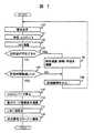
まず、レーダ装置が通常動作中であり、低消費電力モードへ遷移するプロセスでの信号処理部15の処理を、図6のフロー図を用いて説明する。レーダ装置が通常動作中は、ステップ100でレーダ装置から電波を送信する。ステップ101で前方の物体から反射され返ってくる電波を受信し、A/D変換を施す。A/D変換を施したディジタルデータに対し、ステップ102でFFT演算処理する。次にステップ103では、FFT演算の結果から、ある所定のレベル以上の反射波が存在するかどうかを判断する。反射波が存在する場合はステップ104へ進み、FFT演算の結果から相対速度・距離・角度を演算する。次にステップ106へ進み、これらの計測結果をレーダ装置外部へ出力する。これら一連の処理が終了すると、再びステップ100に戻り、計測処理を繰り返す。ステップ103において、FFT演算の結果から、ある所定のレベル以上の反射波が存在しなかった場合は、ステップ105へ進む。ステップ105では、反射波が存在しない時間が所定の時間以上経過したかを判断する。所定の時間に達しない場合はステップ106に進み、通常の計測動作を繰り返す。ステップ105で、反射波が存在しない時間が所定の時間以上経過したと判断された場合はステップ107に進み、A/Dコンバータ14の動作を停止させる。また同時に、低消費電力モードでは不要なハード部分への供給電源を停止させることも可能である。次にステップ108で、信号処理部自身を低消費電力モードへ遷移させる。低消費電力へ遷移させる方法としては、ハード的にマイクロプロセッサへ入力される電気信号を用いる方法や、マイクロプロセッサ内部のソフトウエア指令による方法などがある。ソフトウエア指令により低消費電力モードへ遷移させる場合には、マイクロプロセッサ全体の動作を停止させるソフトウエアスタンバイモードや、マイクロプロセッサ一部を動作させるスリープモードがある。
【0022】
次に低消費電力モードから通常動作モードに復帰する場合について説明する。図1に示すように、レーダ装置は、受信したアナログ信号の振幅を検出する振幅部21とその結果を判断する判断部22を持つ。アナログ回路13からは、図2に示すような受信信号が出力される。レーダの検出範囲に物体が存在しない場合は、反射波が存在しないため、受信信号の振幅は小さい。レーダの検出範囲に物体が進入してきた時には、反射波が発生するため受信信号の振幅が図2に示すように大きくなる。振幅検出部21は、所定のしきい値で受信信号の振幅変動を検出する。その結果をもとに消費電力制御部23は、信号処理部15の動作モードを、低消費電力モードから通常動作モードへ切換える。また同時に、A/Dコンバータ14も通常動作へ切換える。
【0023】
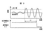
図2に示した例では、受信信号がしきい値を超えると、信号処理部15の動作モードを切換えたが、振幅検出部21が受信信号の振幅変動を検出した後に、判断部22で判断処理を行うことも可能であり、その例を図3と図4に示す。判断部22は、振幅検出部21が検出する受信信号の振幅変動の回数を計測する。図3と図4の例では、しきい値を3回超えると、動作モードを変化させるよう判断する場合の例を示している。このような判断処理を加えることで、より正確な判断が可能となる。また、検出物体の相対的な動きで発生するドップラー信号を受信信号として検出する種類のレーダ装置においては、図3の例は物体の移動速度が遅く、ドップラー周波数が低い場合であり、図4の例は物体の移動速度が早く、ドップラー周波数が高い場合である。判断部22でしきい値を超える回数を計測する方式では、物体の移動速度に応じて、反射信号が受信されてから、信号処理部15の動作モードが遷移するまでの時間を、図3におけるT1や、図4におけるT2のように、変化させることが可能となる。この特性は、高速の移動物体ほど早くみつけられるという特徴を持つため、レーダ装置に適している。
【0024】
また、図1では、アナログ回路13から振幅検出部21へ信号を送っているが、ミキサ12の出力信号を振幅検出部21へ送り、同様の処理を行うことも可能である。
【0025】
次の実施例について図5を用いて説明する。アナログ回路13から出力される受信信号には、本来検出したい物体以外からの反射信号など、余分な周波数成分も含まれている。そこで、アナログ回路の出力信号に対しフィルタ部24で、所定の信号だけ通し、その信号の大きさを振幅検出部21で検出する。ここで、フィルタ部24は、低域通過フィルタ,高域通過フィルタ,帯域通過フィルタ、のいずれかが用いられる。
【0026】
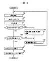
次の実施例について、図5、及び図7の処理フローを用いて説明する。受信信号の状態を検出するフィルタ部24はそのフィルタ定数を信号処理部15からの信号で可変とする機能を持ち、振幅検出部21は受信信号を検出するしきい値を信号処理部15からの信号で可変とする機能を持ち、判断部22はその判断基準を信号処理部15からの信号で可変とする機能をそれぞれ持つ。信号処理部15は、通常動作時に、各周波数帯での振幅レベルなどの受信信号特性を計測しておく。この受信信号の特性を基に、低消費電力モードから、再び通常動作モードへ遷移するための遷移条件を演算し、フィルタ部24,振幅検出部21,判断部22のいずれか一つ以上へ設定しておく。この設定されたしきい値を用いて、通常動作モードへ復帰させることで、時々刻々変化する外部環境に合わせて、レーダ装置1の動作モード切換え条件を可変とできる。この処理の流れを図7に示している。ステップ107までは、図6と同様の処理であるが、ステップ110で、今まで計測された情報をもとに、通常動作モードへ復帰するための条件を演算する。その演算結果をもとに、ステップ111では、フィルタ定数をフィルタ部24へ、受信信号を検出するしきい値を振幅検出部21へ、判断基準を判断部22へ送り設定する。これらの設定は、例えばアナログ回路での抵抗定数の切換えなどにより実現できる。以上の例では、フィルタ部24,振幅検出部21,判断部22のいずれもが、信号処理部15からの信号で、その特性を可変とする場合について説明したが、いずれか一つ以上の特性を可変とする場合についても同様である。
【0027】
また、図1または図5で説明したレーダ装置において、レーダ装置外部から入力される動作モード切換え信号により、通常動作モードと低消費電力モードを切換えることも可能である。
【0028】
また、信号処理部15をマイクロプロセッサで構成する場合、例えば低消費電力モードには、ハードウエアスタンバイモード,ソフトウエアスタンバイモード,スリープモードがある。ハードウエアスタンバイモードとソフトウエアスタンバイモードでは、マイクロプロセッサの所定の端子へ所定の信号を入力することで、通常モードへ復帰することが可能である。図1に示した例では、消費電力制御部23からの信号を所定の端子へ入力することや、レーダ装置外部から入力される動作モード切換え信号を入力することで実現できる。
【0029】
スリープモードの場合は、マイクロプロセッサ内の一部が動作しているため、割り込み信号や、レーダ装置外部からの通信指令によって通常動作モードへ復帰することが可能となる。この場合、低消費電力モードにおいても通信部は動作させることが可能であるので、外部装置との通信において、レーダ装置が低消費電力で動作していることを、外部装置へ送ることが可能である。
【0030】
なお、本発明は、主に電波レーダを中心として実施例を記載しているが、光を使うレーザレーダでも実施可能である。
【0031】
【発明の効果】
以上説明したように、本発明では、
電波を放射し物体からの反射波を受信し、物体との相対速度を計測する、車両用レーダ装置において、
ディジタル信号処理部が、少なくとも通常動作モードと低消費電力モードと2つの動作モードを持ち、
受信信号がある所定の条件に達するかを判断する判断部からの信号を用いて、ディジタル信号部の動作モードを切換える機能を持つことでレーダの検出能力を維持しつつ、消費電力を低減させる機能を持つことができる。
【図面の簡単な説明】
【図1】レーダ装置の構成を示す図。
【図2】受信信号と動作モードの遷移例を示す図。
【図3】受信信号と動作モードの遷移例を示す図。
【図4】受信信号と動作モードの遷移例を示す図。
【図5】レーダ装置の構成を示す図。
【図6】動作モードを切換える処理フローを示す図。
【図7】動作モードを切換える処理フローを示す図。
【符号の説明】
1…レーダ装置、2…表示器、10…送信アンテナ、11…受信アンテナ、
12…ミキサ、13…アナログ回路、14…A/Dコンバータ、15…信号処理部、17…変調器、18…発信器。[0001]
TECHNICAL FIELD OF THE INVENTION
The present invention relates to a radar device that emits an electromagnetic wave, receives a reflected wave from an object, and detects a distance, a relative speed, and an angle to the object.
[0002]
[Prior art]
2. Description of the Related Art Conventionally, a vehicle radar device radiates electromagnetic waves such as light and radio waves to receive a reflected wave from an object such as a car or an obstacle, and determines the propagation time of the electromagnetic wave, the strength of the reflected wave, and the Doppler shift of the frequency. The distance and the relative speed and direction to the object are measured from the detection result. Although the application field of the radar apparatus is wide, a radar apparatus for a vehicle which is mounted on a car and measures an inter-vehicle distance to a preceding vehicle has recently been developed. On the other hand, as one type of sensing using electromagnetic waves, application to fields such as home security is also being studied.
[0003]
2. Description of the Related Art In a radar apparatus using laser light, a pulse method of transmitting a pulsed laser light and measuring a distance from a round trip time of a pulse wave is used. In a radar device using radio waves, there are several methods for measuring the distance to an object and the relative speed. A two-frequency CW (Continuous Wave) method for switching two frequencies, an FMCW (Frequency Modulated Continuous Wave) method for performing triangular modulation on a transmission frequency, and a pulse for transmitting a pulse wave and measuring a distance from a reciprocation time of the pulse wave. Methods are known. In the two-frequency CW method and the FMCW method, a received signal is subjected to FFT processing (Fast Fourier Transform), and a distance to an object and a relative speed are measured from frequency / phase / amplitude information of an obtained peak signal of a frequency spectrum. .
[0004]
When such a radar device is used for a vehicle, all the power required for operation must be generated inside the vehicle. For example, as disclosed in
[0005]
[Patent Document 1]
JP-A-8-136646 [0006]
[Problems to be solved by the invention]
However, in the conventional method, while the power consumption can be reduced, the range that should be covered by the radar is searched in a time-division manner, and there is a possibility that the object detection may leak.
[0007]
An object of the present invention is to provide a vehicular radar device having a function of reducing power consumption while maintaining radar detection capability.
[0008]
[Means for Solving the Problems]
The object is to provide a radar device that includes a transmission unit that emits an electromagnetic wave and a reception unit that receives an electromagnetic wave reflected by an object, and that detects the object. In the radar device, the first operation mode and the first operation mode The second operation mode consumes less energy, and is achieved by switching between the first operation mode and the second operation mode based on an output signal of the receiving unit. Further, the object is to provide a radar device having a function of detecting any one or more of a relative speed, a distance, and a direction with respect to an object, a transmitting unit that emits an electromagnetic wave, and a transmission signal that is reflected by the object. It has a receiving unit for receiving a reflected wave, an A / D converting unit for A / D converting a received signal, and a digital signal processing unit for processing the A / D converted digital signal. The digital signal processing unit has at least a normal operation. Mode and a low power consumption mode, and has a function of switching the operation mode of the digital signal section by using a signal from a determination section for determining whether a received signal has reached a predetermined condition. This can be achieved by a radar device characterized by the following.
[0009]
When the radar device is in the low power consumption mode, the determination unit has a function of determining that the amplitude of the received signal has exceeded a predetermined threshold, and sets the operation mode of the digital signal processing unit to the low power consumption mode. The present invention can also be achieved by a radar device having a function of switching from a power mode to a normal operation mode.
[0010]
Further, when the radar device is in the low power consumption mode, the determination unit has a frequency filter, and when the amplitude of the received signal passing through the frequency filter exceeds a predetermined threshold, the operation mode of the digital signal processing unit is changed. Can be achieved also by a radar device having a function of switching from the low power consumption mode to the normal operation mode.
[0011]
Further, the present invention can also be achieved by a radar device, wherein the determination unit has a function of counting the number of times the threshold value is exceeded.
[0012]
Further, the determination unit has a function of making the determination conditions variable, and has a function of setting the determination conditions of the determination unit when the digital signal unit is in a normal operation.
[0013]
Further, the digital signal processing unit of the radar device has a judgment processing unit for judging whether or not a received signal satisfies a predetermined condition, and when the digital signal processing unit is in a normal operation mode, the judgment processing unit In this case, the digital signal processing section can be switched from the normal operation mode to the low power consumption mode by the above-mentioned command.
[0014]
Further, the digital signal processing unit of the radar device has a judgment processing unit for judging whether or not a received signal satisfies a predetermined condition, and has a function of making the judgment condition of the judgment processing unit variable. It can also be achieved by a radar device that performs the above.
[0015]
Further, the above-mentioned radar apparatus can also be achieved by a radar apparatus having a function of inputting a signal for switching an operation mode from outside the radar apparatus.
[0016]
Further, in the above radar apparatus, the radar apparatus has communication means for communication with the outside, and has a means for communicating the state of the operation mode of the normal operation mode or the low power consumption mode with the outside. it can.
[0017]
BEST MODE FOR CARRYING OUT THE INVENTION
An embodiment of the present invention will be described below with reference to FIGS.
[0018]
FIG. 1 is a diagram showing a block diagram of a radar apparatus according to the present invention.
[0019]
The
[0020]
A radio signal reflected and returned from an object such as a vehicle or an obstacle is received by the receiving antenna 11, and the
[0021]
First, the processing of the
[0022]
Next, the case of returning from the low power consumption mode to the normal operation mode will be described. As shown in FIG. 1, the radar device has an
[0023]
In the example shown in FIG. 2, when the received signal exceeds the threshold value, the operation mode of the
[0024]
In FIG. 1, a signal is sent from the
[0025]
The next embodiment will be described with reference to FIG. The received signal output from the
[0026]
The next embodiment will be described with reference to the processing flows of FIG. 5 and FIG. The
[0027]
In the radar device described with reference to FIG. 1 or FIG. 5, it is also possible to switch between the normal operation mode and the low power consumption mode by an operation mode switching signal input from outside the radar device.
[0028]
When the
[0029]
In the case of the sleep mode, since a part of the microprocessor operates, it is possible to return to the normal operation mode by an interrupt signal or a communication command from outside the radar device. In this case, since the communication unit can be operated even in the low power consumption mode, it is possible to notify the external device that the radar device is operating with low power consumption in communication with the external device. is there.
[0030]
Although the present invention has been described mainly with reference to radio wave radar, the present invention can also be practiced with laser radar using light.
[0031]
【The invention's effect】
As described above, in the present invention,
In a vehicle radar device that radiates radio waves and receives reflected waves from an object and measures the relative speed with the object,
The digital signal processing unit has at least two operation modes, a normal operation mode and a low power consumption mode,
A function to reduce the power consumption while maintaining the radar detection capability by having the function of switching the operation mode of the digital signal unit using the signal from the judgment unit that judges whether the received signal reaches a predetermined condition. Can have.
[Brief description of the drawings]
FIG. 1 is a diagram showing a configuration of a radar device.
FIG. 2 is a diagram showing a transition example of a reception signal and an operation mode.
FIG. 3 is a diagram showing a transition example of a reception signal and an operation mode.
FIG. 4 is a diagram showing a transition example of a reception signal and an operation mode.
FIG. 5 is a diagram showing a configuration of a radar device.
FIG. 6 is a diagram showing a processing flow for switching operation modes.
FIG. 7 is a diagram showing a processing flow for switching operation modes.
[Explanation of symbols]
DESCRIPTION OF
12 mixer, 13 analog circuit, 14 A / D converter, 15 signal processing unit, 17 modulator, 18 transmitter.
Claims (10)
Translated fromJapanese物体によって反射された電磁波を受信する受信部とを備え、
前記物体を検出するレーダ装置において、
第1の動作モードと、
前記第1の動作モードよりも消費エネルギーが少ない第2の動作モードとを備え、
前記受信部の出力信号に基づいて、前記第1の動作モードと第2の動作モードとを切換えることを特徴とするレーダ装置。A transmission unit that emits electromagnetic waves,
A receiving unit that receives the electromagnetic wave reflected by the object,
In a radar device for detecting the object,
A first mode of operation;
A second operation mode that consumes less energy than the first operation mode,
A radar apparatus, wherein the first operation mode and the second operation mode are switched based on an output signal of the reception unit.
A/D変換したディジタル信号を処理するディジタル信号処理部とを備え、
前記物体との相対速度,距離,方向のいずれか一つ以上を検出する機能を持つレーダ装置であって、
ディジタル信号処理部が、少なくとも前記第1の動作モードと前記第2の動作モードと2つの動作モードを持ち、
受信信号がある所定の条件に達したかどうかを判断する判断部からの信号を用いて、ディジタル信号部の動作モードを切換える機能を持つことを特徴とするレーダ装置。The A / D converter according to claim 1, wherein the A / D converter converts the signal from the receiving unit into an analog signal.
A digital signal processing unit for processing the digital signal after A / D conversion,
A radar device having a function of detecting at least one of a relative speed, a distance, and a direction with respect to the object,
A digital signal processing unit having at least two operation modes: the first operation mode and the second operation mode;
A radar apparatus having a function of switching an operation mode of a digital signal unit using a signal from a determination unit that determines whether a received signal has reached a predetermined condition.
判断部は、受信信号の振幅が所定のしきい値を超えたことを判断する機能を持ち、ディジタル信号処理部の動作モードを、第2の動作モードから第1の動作モードへ切換える機能を持つことを特徴とする、レーダ装置。In claim 2, in the second operation mode,
The determining unit has a function of determining that the amplitude of the received signal exceeds a predetermined threshold, and has a function of switching the operation mode of the digital signal processing unit from the second operation mode to the first operation mode. A radar device, characterized in that:
判断部は周波数フィルタを持ち、周波数フィルタを通過する受信信号の振幅が所定のしきい値を超えたときに、ディジタル信号処理部の動作モードを、第2の動作モードから第1の動作モードへ切換える機能を持つことを特徴とする、レーダ装置。In claim 2, in the second operation mode,
The determination unit has a frequency filter, and when the amplitude of the received signal passing through the frequency filter exceeds a predetermined threshold, changes the operation mode of the digital signal processing unit from the second operation mode to the first operation mode. A radar device having a switching function.
判断部に、しきい値が超えた回数をカウントする機能をもつことを特徴とする、レーダ装置。In claim 3,
A radar device, wherein the determination unit has a function of counting the number of times the threshold value is exceeded.
判断部は、その判断条件を可変とする機能を持ち、ディジタル信号部が通常動作時に、該判断部の判断条件を設定する機能を持つことを特徴とする、レーダ装置。In claim 2,
A radar apparatus characterized in that the judging section has a function of making the judging conditions variable, and has a function of setting the judging conditions of the judging section when the digital signal section is in normal operation.
物体との相対速度,距離,方向のいずれか一つ以上を検出する機能を持つレーダ装置において、
ディジタル信号処理部は、少なくとも第1の動作モードと第2の動作モードと2つの動作モードを持ち、
ディジタル信号処理部は、その内部に受信信号がある所定の条件に達するかを判断する判断処理部を持ち、
ディジタル信号処理部が第1の動作モードにあるときに、判断処理部からの指令で、ディジタル信号処理部を、第1の動作モードから第2の動作モードへ切換える機能を持つことを特徴とするレーダ装置。A transmitting unit that emits an electromagnetic wave, a receiving unit that receives a reflected wave that returns when a transmitted signal is reflected by an object, an A / D converting unit that A / D converts the received signal, and a digital signal that is A / D converted Has a digital signal processing unit that processes
In a radar device that has a function to detect any one or more of relative speed, distance, and direction to an object,
The digital signal processing unit has at least two operation modes, a first operation mode and a second operation mode,
The digital signal processing unit has a judgment processing unit for judging whether a received signal satisfies a predetermined condition,
When the digital signal processing unit is in the first operation mode, the digital signal processing unit has a function of switching the digital signal processing unit from the first operation mode to the second operation mode in response to a command from the determination processing unit. Radar equipment.
物体との相対速度,距離,方向のいずれか一つ以上を検出する機能を持つレーダ装置において、
ディジタル信号処理部は、少なくとも通常動作モードと低消費電力モードと2つの動作モードを持ち、
動作モードを切換える信号を、レーダ装置外部から入力できる機能を持つことを特徴とするレーダ装置。A transmitting unit that emits an electromagnetic wave, a receiving unit that receives a reflected wave that returns when a transmission signal is reflected by an object, an A / D conversion unit that A / D converts the received signal, and a digital signal that is A / D converted Has a digital signal processing unit that processes
In a radar device that has a function to detect any one or more of relative speed, distance, and direction to an object,
The digital signal processing unit has at least two operation modes, a normal operation mode and a low power consumption mode,
A radar device having a function of inputting a signal for switching an operation mode from outside the radar device.
Priority Applications (4)
| Application Number | Priority Date | Filing Date | Title |
|---|---|---|---|
| JP2003099790AJP2004309190A (en) | 2003-04-03 | 2003-04-03 | Radar equipment |
| US10/785,007US7109915B2 (en) | 2003-04-03 | 2004-02-25 | Radar apparatus |
| DE602004010947TDE602004010947T2 (en) | 2003-04-03 | 2004-02-26 | Radar device with energy saving measures |
| EP04004438AEP1464989B1 (en) | 2003-04-03 | 2004-02-26 | Radar apparatus with power saving features |
Applications Claiming Priority (1)
| Application Number | Priority Date | Filing Date | Title |
|---|---|---|---|
| JP2003099790AJP2004309190A (en) | 2003-04-03 | 2003-04-03 | Radar equipment |
Publications (1)
| Publication Number | Publication Date |
|---|---|
| JP2004309190Atrue JP2004309190A (en) | 2004-11-04 |
Family
ID=32844699
Family Applications (1)
| Application Number | Title | Priority Date | Filing Date |
|---|---|---|---|
| JP2003099790APendingJP2004309190A (en) | 2003-04-03 | 2003-04-03 | Radar equipment |
Country Status (4)
| Country | Link |
|---|---|
| US (1) | US7109915B2 (en) |
| EP (1) | EP1464989B1 (en) |
| JP (1) | JP2004309190A (en) |
| DE (1) | DE602004010947T2 (en) |
Cited By (5)
| Publication number | Priority date | Publication date | Assignee | Title |
|---|---|---|---|---|
| KR101777011B1 (en) | 2015-10-01 | 2017-09-26 | 재단법인대구경북과학기술원 | Apparatus and method for processing radar signal in accordance with the energy of the radar sensor |
| WO2019202802A1 (en)* | 2018-04-19 | 2019-10-24 | 京セラ株式会社 | Electronic device, method for controlling electronic device, and program for controlling electronic device |
| CN111095384A (en)* | 2017-09-22 | 2020-05-01 | 索尼公司 | Information processing device, autonomous mobile device, method and program |
| JP2020073942A (en)* | 2019-12-25 | 2020-05-14 | 京セラ株式会社 | Electronic apparatus, control method of electronic apparatus, and control program of electronic apparatus |
| JP2020514750A (en)* | 2017-03-16 | 2020-05-21 | コグニティヴ システムズ コーポレイション | Controlling the wireless state of motion detection |
Families Citing this family (15)
| Publication number | Priority date | Publication date | Assignee | Title |
|---|---|---|---|---|
| JP2004309190A (en)* | 2003-04-03 | 2004-11-04 | Hitachi Ltd | Radar equipment |
| JP4443269B2 (en)* | 2004-03-08 | 2010-03-31 | 富士通テン株式会社 | Evaluation method for spread spectrum radar apparatus and spread spectrum radar apparatus |
| CN1839325A (en)* | 2004-04-22 | 2006-09-27 | 松下电器产业株式会社 | Contactless Reader |
| JP3887000B2 (en)* | 2004-06-11 | 2007-02-28 | シャープ株式会社 | Electronic circuit equipment |
| US7400290B2 (en)* | 2005-12-30 | 2008-07-15 | Valeo Raytheon Systems, Inc. | Vehicle radar system having multiple operating modes |
| JP4224096B2 (en)* | 2006-10-27 | 2009-02-12 | 三菱電機株式会社 | Radar equipment |
| JP4484895B2 (en)* | 2007-04-23 | 2010-06-16 | 三菱電機株式会社 | In-vehicle radar system |
| GB0710209D0 (en)* | 2007-05-29 | 2007-07-04 | Cambridge Consultants | Radar system |
| JP2009025959A (en)* | 2007-07-18 | 2009-02-05 | Mazda Motor Corp | Vehicle obstacle detection device |
| JP4564041B2 (en)* | 2007-11-27 | 2010-10-20 | 本田技研工業株式会社 | Vehicle travel control device |
| US8593334B2 (en)* | 2011-07-29 | 2013-11-26 | The Boeing Company | Split aperture monopulse antenna system |
| US10630249B2 (en) | 2017-08-04 | 2020-04-21 | Texas Instruments Incorporated | Low power mode of operation for mm-wave radar |
| DE102018215139A1 (en)* | 2018-09-06 | 2020-03-12 | Robert Bosch Gmbh | Operating method and control unit for a data / signal evaluation system, data / signal evaluation system, ultrasound operating assistance system and working device |
| FR3100775B1 (en)* | 2019-09-12 | 2021-08-06 | Continental Automotive | PROCESS FOR OPENING A MOTOR VEHICLE OPENER BY MOTION DETECTION, USING A DOPPLER RADAR AND ASSOCIATED DETECTION DEVICE |
| CN114096734B (en)* | 2019-07-17 | 2023-09-19 | 纬湃科技有限责任公司 | Method for opening an opening part of a motor vehicle by means of movement detection using doppler radar and associated detection device |
Family Cites Families (15)
| Publication number | Priority date | Publication date | Assignee | Title |
|---|---|---|---|---|
| US4401987A (en)* | 1979-04-03 | 1983-08-30 | Sonatech, Inc. | Ranging system having reduced recognition jitter |
| US5182810A (en)* | 1989-05-31 | 1993-01-26 | Dallas Semiconductor Corp. | Isolation gates to permit selective power-downs within a closely-coupled multi-chip system |
| JP2989428B2 (en)* | 1993-06-17 | 1999-12-13 | 本田技研工業株式会社 | Time-sharing FM radar system |
| US5416488A (en)* | 1993-12-27 | 1995-05-16 | Motorola, Inc. | Radar return signal processing method |
| US5471212A (en)* | 1994-04-26 | 1995-11-28 | Texas Instruments Incorporated | Multi-stage transponder wake-up, method and structure |
| JP3300558B2 (en) | 1994-11-10 | 2002-07-08 | 本田技研工業株式会社 | Automotive multi-channel radar device |
| US5896103A (en)* | 1996-10-15 | 1999-04-20 | Honeywell Inc. | Method and aparatus for dynamically calibrating a radar receiver |
| US5828333A (en)* | 1997-01-21 | 1998-10-27 | Northrop Grumman Corporation | Multiple access diplex doppler radar |
| JPH10248162A (en) | 1997-02-28 | 1998-09-14 | Yupiteru Ind Co Ltd | Power-saving microwave detector |
| JPH1138121A (en)* | 1997-07-15 | 1999-02-12 | Mitsubishi Electric Corp | Automotive radar equipment |
| DE19803660C2 (en)* | 1998-01-30 | 2001-07-05 | Siemens Ag | Motor vehicle radar |
| JP3320023B2 (en)* | 1998-11-18 | 2002-09-03 | ユピテル工業株式会社 | Microwave detector |
| DE19921844A1 (en)* | 1999-05-11 | 2000-11-23 | Bosch Gmbh Robert | Device for the detection of objects in the vicinity of a vehicle |
| JP3893912B2 (en) | 2001-07-18 | 2007-03-14 | 株式会社日立製作所 | Vehicle control device |
| JP2004309190A (en)* | 2003-04-03 | 2004-11-04 | Hitachi Ltd | Radar equipment |
- 2003
- 2003-04-03JPJP2003099790Apatent/JP2004309190A/enactivePending
- 2004
- 2004-02-25USUS10/785,007patent/US7109915B2/ennot_activeExpired - Fee Related
- 2004-02-26EPEP04004438Apatent/EP1464989B1/ennot_activeExpired - Lifetime
- 2004-02-26DEDE602004010947Tpatent/DE602004010947T2/ennot_activeExpired - Fee Related
Cited By (7)
| Publication number | Priority date | Publication date | Assignee | Title |
|---|---|---|---|---|
| KR101777011B1 (en) | 2015-10-01 | 2017-09-26 | 재단법인대구경북과학기술원 | Apparatus and method for processing radar signal in accordance with the energy of the radar sensor |
| JP2020514750A (en)* | 2017-03-16 | 2020-05-21 | コグニティヴ システムズ コーポレイション | Controlling the wireless state of motion detection |
| JP7003148B2 (en) | 2017-03-16 | 2022-01-20 | コグニティヴ システムズ コーポレイション | Controlling the wireless state of motion detection |
| CN111095384A (en)* | 2017-09-22 | 2020-05-01 | 索尼公司 | Information processing device, autonomous mobile device, method and program |
| WO2019202802A1 (en)* | 2018-04-19 | 2019-10-24 | 京セラ株式会社 | Electronic device, method for controlling electronic device, and program for controlling electronic device |
| JP2019190881A (en)* | 2018-04-19 | 2019-10-31 | 京セラ株式会社 | Electronic device, and method and program for controlling the same |
| JP2020073942A (en)* | 2019-12-25 | 2020-05-14 | 京セラ株式会社 | Electronic apparatus, control method of electronic apparatus, and control program of electronic apparatus |
Also Published As
| Publication number | Publication date |
|---|---|
| DE602004010947D1 (en) | 2008-02-14 |
| EP1464989A1 (en) | 2004-10-06 |
| EP1464989B1 (en) | 2008-01-02 |
| US20040196173A1 (en) | 2004-10-07 |
| DE602004010947T2 (en) | 2008-12-24 |
| US7109915B2 (en) | 2006-09-19 |
Similar Documents
| Publication | Publication Date | Title |
|---|---|---|
| JP2004309190A (en) | Radar equipment | |
| KR100588767B1 (en) | Radar sensor device | |
| JP3688255B2 (en) | In-vehicle radio radar apparatus and signal processing method thereof | |
| JP2006029858A5 (en) | ||
| EP1619519A1 (en) | FM-CW radar system | |
| US7443336B2 (en) | In-vehicle pulse radar device | |
| KR101598344B1 (en) | Fmcw radar system usign adaptive scheduler | |
| JP4032881B2 (en) | FM-CW radar equipment | |
| JP2002168947A (en) | Fm-cw radar system | |
| US7427946B2 (en) | Object sensing apparatus | |
| JPH08189965A (en) | Vehicle radar device | |
| JP5697904B2 (en) | Radar apparatus and detection method | |
| JP4549587B2 (en) | FMCW radar equipment | |
| JP2009058335A (en) | Radar device and relative distance detection method | |
| US6445336B2 (en) | Radar device and on-vehicle radar device | |
| JP4353583B2 (en) | 1 antenna millimeter wave radar system | |
| JP3695650B2 (en) | Object detection device | |
| JP2004245647A (en) | Short-range radar device and vehicle equipped with short-range radar device | |
| JP2003222673A (en) | Distance measuring device and distance measuring method | |
| JP2006098099A (en) | Moving body detection device | |
| JP2003222672A (en) | Radar equipment | |
| JP2005156442A (en) | Short range sensor | |
| JP2009198272A (en) | Radar system | |
| JP4225804B2 (en) | Radar equipment | |
| JP2004219167A (en) | Microwave sensor system |
Legal Events
| Date | Code | Title | Description |
|---|---|---|---|
| A621 | Written request for application examination | Free format text:JAPANESE INTERMEDIATE CODE: A621 Effective date:20050517 | |
| RD01 | Notification of change of attorney | Free format text:JAPANESE INTERMEDIATE CODE: A7421 Effective date:20060420 | |
| A977 | Report on retrieval | Free format text:JAPANESE INTERMEDIATE CODE: A971007 Effective date:20061031 | |
| A131 | Notification of reasons for refusal | Free format text:JAPANESE INTERMEDIATE CODE: A131 Effective date:20061114 | |
| A521 | Request for written amendment filed | Free format text:JAPANESE INTERMEDIATE CODE: A523 Effective date:20070111 | |
| A02 | Decision of refusal | Free format text:JAPANESE INTERMEDIATE CODE: A02 Effective date:20070717 |