JP2004296736A - Light emitting device - Google Patents
Light emitting deviceDownload PDFInfo
- Publication number
- JP2004296736A JP2004296736AJP2003086332AJP2003086332AJP2004296736AJP 2004296736 AJP2004296736 AJP 2004296736AJP 2003086332 AJP2003086332 AJP 2003086332AJP 2003086332 AJP2003086332 AJP 2003086332AJP 2004296736 AJP2004296736 AJP 2004296736A
- Authority
- JP
- Japan
- Prior art keywords
- led
- voltage
- light emitting
- temperature
- drive
- Prior art date
- Legal status (The legal status is an assumption and is not a legal conclusion. Google has not performed a legal analysis and makes no representation as to the accuracy of the status listed.)
- Pending
Links
- 230000008859changeEffects0.000claimsabstractdescription14
- 238000005259measurementMethods0.000claimsdescription11
- 230000007423decreaseEffects0.000description12
- 230000020169heat generationEffects0.000description7
- 238000010586diagramMethods0.000description4
- 238000000034methodMethods0.000description4
- 238000001816coolingMethods0.000description3
- 230000006378damageEffects0.000description3
- 230000009467reductionEffects0.000description3
- 239000004065semiconductorSubstances0.000description3
- 238000001514detection methodMethods0.000description2
- 230000004069differentiationEffects0.000description2
- 238000000295emission spectrumMethods0.000description2
- 230000008901benefitEffects0.000description1
- 230000006866deteriorationEffects0.000description1
- 230000000694effectsEffects0.000description1
- 239000012530fluidSubstances0.000description1
- 230000006870functionEffects0.000description1
- 238000010438heat treatmentMethods0.000description1
- 239000007788liquidSubstances0.000description1
- 150000004767nitridesChemical class0.000description1
- 230000000630rising effectEffects0.000description1
Images


Landscapes
- Led Devices (AREA)
Abstract
Description
Translated fromJapanese【0001】
【発明の属する技術分野】
本発明は、発光素子を効率良く発光させるために、温度制御を行う発光装置に関するものである。
【0002】
【従来の技術】
一般に、発光ダイオード等の発光素子は、その温度や周囲温度の変化により、発光出力や発光スペクトルが変動することが知られており、このような、発光出力や発光ペクトルの変動を制御するために、発光素子の温度制御を行っている。このような技術として、発光素子の温度を検出する温度検出手段と、発光素子を加熱する発熱手段と、温度検出手段の出力に基づいて発熱手段を制御する制御手段とを設けることにより、発光素子の時間経過に伴う温度変動を抑制して、発光素子の発光出力の変動を抑制する技術(例えば、特許文献1)が開示されている。
【0003】
また、発光素子の温度を検出する温度検出手段と、発光素子の駆動電力を制御する駆動電力制御手段と、温度検出手段により検出された温度情報、駆動電力手段の駆動電力情報に基づいて発光素子の波長を算出して、この算出値に基づいて駆動電力制御手段を制御する演算処理制御手段とを設けることにより、発光素子の発光波長を制御する技術(例えば、特許文献2)が開示されている。
【0004】
【特許文献1】
特開平6−45654号公報
【特許文献2】
特開平6−237013号公報
【0005】
【発明が解決しようとする課題】
しかしながら、上記特許文献1および特許文献2に記載の技術では、発光素子の温度を検出する温度検出手段として、熱電対、サーミスタ等の温度センサが必要であり、コストが高くなるという問題があった。また、熱電対やサーミスタ等の温度センサを使用した場合には、温度検出に熱伝導による時間的な遅れが発生するために、制御に遅れが生じるという問題があった。
【0006】
本発明は、上記問題点を解決するためのもので、発光素子の温度制御を確実に行うことにより、発光素子を効率良く発光させる発光装置を低コストで提供することを目的とする。
【0007】
【課題を解決するための手段】
上記問題点を解決するために、本発明の発光装置は、発光素子と、発光素子の駆動電流を制御する駆動電流制御手段と、発光素子の電圧を測定する電圧測定手段と、発光素子を定電流で駆動する時に、電圧測定手段から電圧の測定値を順次取得して電圧の変化量を算出し、この変化量に基づいて駆動電流制御手段を制御する演算制御手段とを設けたことを特徴とするものであり、電圧の変化量に基づいて駆動電流を制御することにより、発光素子の温度制御を確実に行うことができる。
【0008】
【発明の実施の形態】
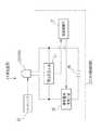
図1は、本発明の発光装置の電気的構成を示すブロック図である。発光装置10は、発光ダイオード(以下LEDと省略する)11と、LED駆動回路12と、ヒートシンク13とで構成されている。
【0009】
本実施形態においては、LED11として高輝度青色発光ダイオード(例えば、InGaN)を用いて説明を行うが、これに限るものではない。以下に、このLED11の特性について説明を行う。LED11を高電流駆動した時の時間経過に対する電圧変化を図2に示す。図2は、定電流(2A)で駆動した時のLED11の時間−電圧特性を示すグラフであり、横軸が経過時間(s)、縦軸が駆動電圧(V)である。このような高電流駆動時には、LED11の発熱により一般的な電圧低下が発生する。この電圧低下は、LED11の駆動開始(位置A)から約3秒後まで発生する。この時、グラフの変曲点(位置B)に達しており、それ以降は、逆に電圧増加が発生して、約8秒後に位置Cに到達している。
【0010】
図3は、LED11の電圧−光出力特性を示すグラフである。このグラフのデータは、図2の時間−電圧特性を示すグラフのデータと同じであり、LED11を2Aの定電流で駆動している。このグラフの横軸は駆動電圧(V)、縦軸は光出力(mW)を示している。LED11の駆動開始時は、右上端の位置Aであり、その後、時間経過とともに、駆動電圧及び光出力が低下し、約3秒後に変曲点(位置B)に到達する。その後、光出力は低下し続けるが、駆動電圧は、逆に増加を開始して、駆動開始から約8秒後に左下端の位置Cに到達する。
【0011】
このグラフより、駆動開始(位置A)から、時間の経過とともに、LED11の発熱により、徐々に発光効率が低下し、かつ駆動電圧が減少することが分かる(図中領域a)。さらに、LED11の発熱が進むと変曲点(位置B)を過ぎて、光出力は領域aの時と同じように低下するが、駆動電圧は逆に上昇に転じる(図中領域b)。これは、光出力の低下、つまり投入された駆動電力が光に変換される効率が、LED11の発熱により低下して、この低下の割合が、発熱による半導体の抵抗低下による駆動電圧の減少を上回ったためであると解釈できる。この領域bでは、急速に、光出力の低下→発熱→駆動電圧の上昇→発熱の増加→光出力の低下と帰還がかかり、LED11の破壊に至る。
【0012】
よって、LED11の破壊を防ぐためには、LED11の電圧測定を逐次行い、単位時間当たりの電圧の変化量、すなわち、電圧の時間微分(dV/dt)を算出することにより、LED11の温度が、領域aの範囲内であるか、変曲点(位置B)であるか、領域bの範囲内であるかを判断することが可能である。
【0013】
変曲点(位置B)においては、電圧の時間微分(dV/dt)=0となるので、これを閾値として変曲点(位置B)に至ってるかどうかを判断して、この閾値に到達した時は、LED11の温度上昇が大きいので、駆動電力(駆動電圧×駆動電流)を減らせば、温度上昇を抑制できる。これにより、LED11の破壊を防止でき、駆動電力に対して効率良く発光させることができる。
【0014】
次に、LED駆動回路12の説明を行う。LED駆動回路12は、LED11の駆動電圧を測定する電圧測定回路14と、駆動電流を制御する駆動電流制御回路15と、LED11を駆動するための電源である駆動用DC16と、演算制御部17とで構成されている。電圧測定回路14及び駆動用DC16は、LED11に対して並列に接続されており、駆動電流制御回路15は、LED11に対して直列に接続されている。また、演算制御部17は、電圧測定回路14及び駆動電流制御回路15に接続されている。
【0015】
演算制御部17は、電圧測定回路14が測定した電圧値を順次取得して、単位時間当たりの電圧変化量、すなわち、電圧の時間微分(dV/dt)を算出する。演算制御部17は、この算出値に基づいて、図3に示す位置Bの変曲点(dV/dt=0)に到達したか否かの判断を行い、変曲点Bに到達したと判断した場合には、駆動電流制御回路15を制御して、電圧の時間微分(dV/dt)が、0より小さい範囲内で駆動するように駆動電流を制限・制御する。また、閾値は変曲点(dV/dt=0)ではなく、dV/dt<0の領域、すなわち領域b内に設けても良い。この場合も、電圧の時間微分(dV/dt)が、閾値より小さい範囲内で駆動するように駆動電流を制限・制御すれば良い。
【0016】
ヒートシンク13は、LED11の内部で発生する熱を冷却するために設けられた部品である。ヒートシンクは、熱の消費体である半導体素子の内部で発生する熱を周囲の冷たい流動体(気体または液体)に移す機能を持っており、半導体を冷却するのに最も実用的で、且つ経済的な部品として知られている。
【0017】
次に、上記実施形態の作用について説明する。発光装置10は、LED駆動回路12により駆動されて発光する。窒化物系青色発光ダイオードであるLED11を定電流で駆動する場合は、一般的な駆動条件において、1℃上昇時の発光効率の低下は、−0.43%/℃、電圧の低下は、−0.006V/℃(駆動電圧が3.3Vとすると、0.18%/℃程度)である。
【0018】
また、高電流注入時には、LED11に投入電力が大きく、温度上昇に伴う発光効率低下による温度上昇が加わることにより、電圧の時間変化量、すなわち電圧の時間微分(dV/dt)は、マイナス(領域a)からプラス(領域b)に転じる。この電圧特性が変曲点(位置B)を越えた(dV/dt>0)の領域bでは、非常に短時間(数〜数十秒)程度しか駆動出来ず、このまま駆動すると破壊に至る。
【0019】
LED11がLED駆動回路12により駆動され発光している時、電圧測定回路14は、LED11の駆動電圧を測定する。LED11の駆動中は、この駆動電圧の測定値は、演算制御部17にて順次取得される。演算制御部17は、取得した測定値に基づいて、電圧の時間変化量、すなわち電圧の時間微分(dV/dt)を算出し、この算出値に基づいて、図3に示す位置Bの変曲点(dV/dt=0)に到達したか否かの判断を行い、変曲点Bに到達したと判断された場合には、駆動電流制御回路15を制御して、電圧の時間微分(dV/dt)が0より小さい範囲内で駆動するように、必要なLED動作時間に応じて駆動電流を制限・制御する。これにより、LED11の温度上昇を制御することが可能であり、LED11が温度上昇により破壊されることを防止できる。また、駆動電力に対して、LED11を効率良く発光させることができる。
【0020】
変曲点Bに到達していないと判断された場合には、演算制御部17は、駆動電流制御回路15により、LED11の定電流駆動を継続させる。
【0021】
また、閾値は変曲点(dV/dt=0)ではなく、dV/dt<0の領域、すなわち領域b内に設けても良い。この場合も、電圧の時間微分(dV/dt)が、閾値より小さい範囲内で駆動するように、必要なLED動作時間に応じて駆動電流を制限・制御すれば良い。
【0022】
さらに、LED11の各電圧時間微分(dV/dt)の値に対応するLED11の温度を演算制御部17のメモリに記憶させておくことにより、この時間微分の値に対応する温度を順次参照して駆動電流を制限・制御すれば、より細かい温度制御が可能である。
【0023】
また、LED11の発熱が小さい、定格以下の電流で駆動した時の電圧値と、一定電流で駆動開始後、一定時間経過後の電圧値との差を算出して、この差が小さくなった時には、LED11の温度が上昇していることが推測できる。これにより、同一電流における発光効率そのものの低下と、LEDの温度上昇による発光効率の低下という異なるモードごとのLEDチップの劣化率を割り出すことができる。
【0024】
なお、本実施形態においては、LEDを駆動するのに駆動用DC電源を用いたが、これに限るものではなく、例えば、パルス直流電源でも良い。この場合は、駆動電圧Vfの時間に対する微分値を算出することにより、LEDの温度上昇に関する情報を取得して、この情報に基づいて、駆動電圧やパルス幅を適宜制御することにより、LEDの発熱を一定値以下に制御することが可能であり、LEDを駆動電力に対して効率良く発光させることができる。
【0025】
また、本実施形態においては、1つのLEDを使用するように説明したが、複数のLEDで構成されるLEDアレイを使用しても良い。この場合は、LEDの駆動電圧の時間変化に基づいてLEDの温度を検知して、駆動電流を制御する制御手段を1個以上のLEDに設ければ良い。これにより、LEDアレイ内の温度分布を知ることができる。また、サーミスター等の温度計測用素子を用いて温度を測定するよりも、熱伝導による時間の遅れがない分、LEDの温度を迅速に検出することができる。このため、LEDのパルス駆動や、フラッシュのような駆動において温度上昇を検出する手段として有効である。
【0026】
さらに、本実施形態の発光装置に、発光量を測定する手段を設け、LEDに投入する電力の損失に対する発熱量が一定値以下で駆動するように、LEDに投入する電力を制御するようにしても良い。あるいは、LEDの冷却のために、例えばヒートシンクとファン等を設けた場合、このファンの風量により、ヒートシンクによるLEDの冷却量を制御するために、この電圧変動値を用いて制御することも可能である。
【0027】
また、本実施形態の発光装置に、LEDの温度を測定する温度測定手段を設け、この温度測定手段により測定された温度と、LEDを定電流駆動したときの電圧値から換算される温度との差を算出して、この差が一定値の範囲内で駆動するように、LEDに投入する電力を制御するようにしても良い。
【0028】
【発明の効果】
以上説明したように、本発明の発光装置は、発光素子の電圧の時間変化量に基づいて、発光素子の温度変化を制御するので、熱電対やサーミスタ等の温度センサを使用した場合の熱伝導による温度検出の遅れがないので、制御の遅れが発生せずに確実な温度制御が可能であるため、温度上昇による発光素子の破壊を防止することができる。また、発光素子を駆動電力に対して効率的に発光させることが可能である。
【0029】
また、熱電対やサーミスタ等の温度センサを必要としないため、温度センサを設けた場合と比べて低コストで製造可能である。
【図面の簡単な説明】
【図1】本発明の発光装置の電気的構成を示すブロック図である。
【図2】LEDの時間−電圧特性を示す図である。
【図3】LEDの電圧−光出力特性を示す図である。
【符号の説明】
10 発光装置
11 LED
12 LED駆動回路
13 ヒートシンク
14 電圧測定回路
15 駆動電流測定回路
16 駆動用DC
17 演算制御部[0001]
BACKGROUND OF THE INVENTION
The present invention relates to a light emitting device that performs temperature control in order to cause a light emitting element to emit light efficiently.
[0002]
[Prior art]
In general, it is known that a light emitting element such as a light emitting diode fluctuates in light emission output and light emission spectrum due to changes in its temperature and ambient temperature. In order to control such fluctuations in light output and light emission spectrum. The temperature of the light emitting element is controlled. As such a technique, by providing temperature detecting means for detecting the temperature of the light emitting element, heat generating means for heating the light emitting element, and control means for controlling the heat generating means based on the output of the temperature detecting means, the light emitting element A technique (for example, Patent Document 1) that suppresses fluctuations in light emission output of a light emitting element by suppressing temperature fluctuations with the passage of time is disclosed.
[0003]
Further, a temperature detecting means for detecting the temperature of the light emitting element, a driving power control means for controlling the driving power of the light emitting element, temperature information detected by the temperature detecting means, and a light emitting element based on the driving power information of the driving power means A technique (for example, Patent Document 2) for controlling the light emission wavelength of the light emitting element by providing a calculation processing control means for calculating the wavelength of the light source and providing a calculation processing control means for controlling the drive power control means based on the calculated value is disclosed. Yes.
[0004]
[Patent Document 1]
JP-A-6-45654 [Patent Document 2]
Japanese Patent Laid-Open No. 6-237013
[Problems to be solved by the invention]
However, the techniques described in Patent Document 1 and
[0006]
SUMMARY An advantage of some aspects of the invention is to provide a light emitting device that efficiently emits light from a light emitting element at low cost by reliably controlling the temperature of the light emitting element.
[0007]
[Means for Solving the Problems]
In order to solve the above problems, a light emitting device of the present invention includes a light emitting element, a driving current control unit that controls a driving current of the light emitting element, a voltage measuring unit that measures a voltage of the light emitting element, and a light emitting element. When driving with current, a voltage measurement value is sequentially obtained from the voltage measurement means, a change amount of the voltage is calculated, and an arithmetic control means for controlling the drive current control means based on the change amount is provided. By controlling the drive current based on the amount of change in voltage, the temperature control of the light emitting element can be reliably performed.
[0008]
DETAILED DESCRIPTION OF THE INVENTION
FIG. 1 is a block diagram showing an electrical configuration of the light emitting device of the present invention. The
[0009]
In the present embodiment, a description is given using a high-intensity blue light-emitting diode (for example, InGaN) as the
[0010]
FIG. 3 is a graph showing the voltage-light output characteristics of the
[0011]
From this graph, it can be seen that the light emission efficiency gradually decreases and the drive voltage decreases due to heat generation of the
[0012]
Therefore, in order to prevent the destruction of the
[0013]
At the inflection point (position B), the time derivative of voltage (dV / dt) = 0, so that it is determined whether or not the inflection point (position B) has been reached by using this as a threshold value. In this case, since the temperature rise of the
[0014]
Next, the LED drive circuit 12 will be described. The LED drive circuit 12 includes a
[0015]
The
[0016]
The
[0017]
Next, the operation of the above embodiment will be described. The
[0018]
In addition, when high current is injected, the input electric power is large in the
[0019]
When the
[0020]
When it is determined that the inflection point B has not been reached, the
[0021]
The threshold value may be provided not in the inflection point (dV / dt = 0) but in the region where dV / dt <0, that is, the region b. In this case as well, the drive current may be limited and controlled according to the required LED operation time so that the voltage is time-differentiated (dV / dt) within a range smaller than the threshold value.
[0022]
Furthermore, by storing the temperature of the
[0023]
In addition, the difference between the voltage value when the
[0024]
In the present embodiment, the driving DC power source is used to drive the LED. However, the present invention is not limited to this, and for example, a pulse direct current power source may be used. In this case, by calculating a differential value with respect to time of the drive voltage Vf, information on the temperature rise of the LED is obtained, and based on this information, the drive voltage and the pulse width are appropriately controlled, thereby generating heat of the LED. Can be controlled to a certain value or less, and the LED can emit light efficiently with respect to driving power.
[0025]
Further, in the present embodiment, it has been described that one LED is used, but an LED array including a plurality of LEDs may be used. In this case, one or more LEDs may be provided with a control means for detecting the temperature of the LED based on the change in the LED driving voltage with time and controlling the driving current. Thereby, the temperature distribution in the LED array can be known. In addition, the temperature of the LED can be detected more quickly because there is no time delay due to heat conduction than when the temperature is measured using a temperature measuring element such as a thermistor. For this reason, it is effective as a means for detecting a temperature rise in LED pulse driving or flash driving.
[0026]
Furthermore, the light emitting device of the present embodiment is provided with means for measuring the amount of light emission, and the power input to the LED is controlled so that the heat generation amount for the loss of power input to the LED is driven below a certain value. Also good. Alternatively, for example, when a heat sink and a fan are provided for cooling the LED, it is possible to control using the voltage fluctuation value in order to control the cooling amount of the LED by the heat sink by the air volume of the fan. is there.
[0027]
Further, the light emitting device of the present embodiment is provided with temperature measuring means for measuring the temperature of the LED, and the temperature measured by the temperature measuring means and the temperature converted from the voltage value when the LED is driven at a constant current. The difference may be calculated, and the power supplied to the LED may be controlled so that the difference is driven within a certain range.
[0028]
【The invention's effect】
As described above, since the light-emitting device of the present invention controls the temperature change of the light-emitting element based on the amount of time change of the voltage of the light-emitting element, the heat conduction when a temperature sensor such as a thermocouple or thermistor is used. Since there is no delay in temperature detection due to the above, it is possible to perform reliable temperature control without causing a delay in control, and thus it is possible to prevent the light emitting element from being destroyed due to a temperature rise. In addition, the light emitting element can emit light efficiently with respect to driving power.
[0029]
In addition, since a temperature sensor such as a thermocouple or a thermistor is not required, it can be manufactured at a lower cost than the case where a temperature sensor is provided.
[Brief description of the drawings]
FIG. 1 is a block diagram showing an electrical configuration of a light emitting device of the present invention.
FIG. 2 is a diagram showing time-voltage characteristics of an LED.
FIG. 3 is a diagram showing voltage-light output characteristics of an LED.
[Explanation of symbols]
10
12
17 Calculation control unit
Claims (1)
Translated fromJapanesePriority Applications (1)
| Application Number | Priority Date | Filing Date | Title |
|---|---|---|---|
| JP2003086332AJP2004296736A (en) | 2003-03-26 | 2003-03-26 | Light emitting device |
Applications Claiming Priority (1)
| Application Number | Priority Date | Filing Date | Title |
|---|---|---|---|
| JP2003086332AJP2004296736A (en) | 2003-03-26 | 2003-03-26 | Light emitting device |
Publications (1)
| Publication Number | Publication Date |
|---|---|
| JP2004296736Atrue JP2004296736A (en) | 2004-10-21 |
Family
ID=33401019
Family Applications (1)
| Application Number | Title | Priority Date | Filing Date |
|---|---|---|---|
| JP2003086332APendingJP2004296736A (en) | 2003-03-26 | 2003-03-26 | Light emitting device |
Country Status (1)
| Country | Link |
|---|---|
| JP (1) | JP2004296736A (en) |
Cited By (6)
| Publication number | Priority date | Publication date | Assignee | Title |
|---|---|---|---|---|
| JP2009011676A (en)* | 2007-07-06 | 2009-01-22 | Olympus Corp | Endoscope system |
| US8050728B2 (en) | 2005-03-01 | 2011-11-01 | Masimo Laboratories, Inc. | Multiple wavelength sensor drivers |
| US8801613B2 (en) | 2009-12-04 | 2014-08-12 | Masimo Corporation | Calibration for multi-stage physiological monitors |
| US8965471B2 (en) | 2007-04-21 | 2015-02-24 | Cercacor Laboratories, Inc. | Tissue profile wellness monitor |
| US9839381B1 (en) | 2009-11-24 | 2017-12-12 | Cercacor Laboratories, Inc. | Physiological measurement system with automatic wavelength adjustment |
| US12029586B2 (en) | 2006-10-12 | 2024-07-09 | Masimo Corporation | Oximeter probe off indicator defining probe off space |
- 2003
- 2003-03-26JPJP2003086332Apatent/JP2004296736A/enactivePending
Cited By (40)
| Publication number | Priority date | Publication date | Assignee | Title |
|---|---|---|---|---|
| US10123726B2 (en) | 2005-03-01 | 2018-11-13 | Cercacor Laboratories, Inc. | Configurable physiological measurement system |
| US9241662B2 (en) | 2005-03-01 | 2016-01-26 | Cercacor Laboratories, Inc. | Configurable physiological measurement system |
| JP4879913B2 (en)* | 2005-03-01 | 2012-02-22 | マシモ・ラボラトリーズ・インコーポレーテッド | Multi-wavelength sensor board |
| US8483787B2 (en) | 2005-03-01 | 2013-07-09 | Cercacor Laboratories, Inc. | Multiple wavelength sensor drivers |
| US8626255B2 (en) | 2005-03-01 | 2014-01-07 | Cercacor Laboratories, Inc. | Noninvasive multi-parameter patient monitor |
| US8634889B2 (en) | 2005-03-01 | 2014-01-21 | Cercacor Laboratories, Inc. | Configurable physiological measurement system |
| US8718735B2 (en) | 2005-03-01 | 2014-05-06 | Cercacor Laboratories, Inc. | Physiological parameter confidence measure |
| US12283374B2 (en) | 2005-03-01 | 2025-04-22 | Willow Laboratories, Inc. | Noninvasive multi-parameter patient monitor |
| US8849365B2 (en) | 2005-03-01 | 2014-09-30 | Cercacor Laboratories, Inc. | Multiple wavelength sensor emitters |
| US8912909B2 (en) | 2005-03-01 | 2014-12-16 | Cercacor Laboratories, Inc. | Noninvasive multi-parameter patient monitor |
| US8929964B2 (en) | 2005-03-01 | 2015-01-06 | Cercacor Laboratories, Inc. | Multiple wavelength sensor drivers |
| US12230393B2 (en) | 2005-03-01 | 2025-02-18 | Willow Laboratories, Inc. | Multiple wavelength sensor emitters |
| US9131882B2 (en) | 2005-03-01 | 2015-09-15 | Cercacor Laboratories, Inc. | Noninvasive multi-parameter patient monitor |
| US9167995B2 (en) | 2005-03-01 | 2015-10-27 | Cercacor Laboratories, Inc. | Physiological parameter confidence measure |
| US11545263B2 (en) | 2005-03-01 | 2023-01-03 | Cercacor Laboratories, Inc. | Multiple wavelength sensor emitters |
| US9351675B2 (en) | 2005-03-01 | 2016-05-31 | Cercacor Laboratories, Inc. | Noninvasive multi-parameter patient monitor |
| US9549696B2 (en) | 2005-03-01 | 2017-01-24 | Cercacor Laboratories, Inc. | Physiological parameter confidence measure |
| US9750443B2 (en) | 2005-03-01 | 2017-09-05 | Cercacor Laboratories, Inc. | Multiple wavelength sensor emitters |
| US8050728B2 (en) | 2005-03-01 | 2011-11-01 | Masimo Laboratories, Inc. | Multiple wavelength sensor drivers |
| US11430572B2 (en) | 2005-03-01 | 2022-08-30 | Cercacor Laboratories, Inc. | Multiple wavelength sensor emitters |
| US10984911B2 (en) | 2005-03-01 | 2021-04-20 | Cercacor Laboratories, Inc. | Multiple wavelength sensor emitters |
| US10251585B2 (en) | 2005-03-01 | 2019-04-09 | Cercacor Laboratories, Inc. | Noninvasive multi-parameter patient monitor |
| US10856788B2 (en) | 2005-03-01 | 2020-12-08 | Cercacor Laboratories, Inc. | Noninvasive multi-parameter patient monitor |
| US10327683B2 (en) | 2005-03-01 | 2019-06-25 | Cercacor Laboratories, Inc. | Multiple wavelength sensor emitters |
| US12029586B2 (en) | 2006-10-12 | 2024-07-09 | Masimo Corporation | Oximeter probe off indicator defining probe off space |
| US9848807B2 (en) | 2007-04-21 | 2017-12-26 | Masimo Corporation | Tissue profile wellness monitor |
| US10251586B2 (en) | 2007-04-21 | 2019-04-09 | Masimo Corporation | Tissue profile wellness monitor |
| US10980457B2 (en) | 2007-04-21 | 2021-04-20 | Masimo Corporation | Tissue profile wellness monitor |
| US11647923B2 (en) | 2007-04-21 | 2023-05-16 | Masimo Corporation | Tissue profile wellness monitor |
| US8965471B2 (en) | 2007-04-21 | 2015-02-24 | Cercacor Laboratories, Inc. | Tissue profile wellness monitor |
| US12156733B2 (en) | 2007-04-21 | 2024-12-03 | Masimo Corporation | Tissue profile wellness monitor |
| JP2009011676A (en)* | 2007-07-06 | 2009-01-22 | Olympus Corp | Endoscope system |
| US10750983B2 (en) | 2009-11-24 | 2020-08-25 | Cercacor Laboratories, Inc. | Physiological measurement system with automatic wavelength adjustment |
| US12127833B2 (en) | 2009-11-24 | 2024-10-29 | Willow Laboratories, Inc. | Physiological measurement system with automatic wavelength adjustment |
| US11534087B2 (en) | 2009-11-24 | 2022-12-27 | Cercacor Laboratories, Inc. | Physiological measurement system with automatic wavelength adjustment |
| US9839381B1 (en) | 2009-11-24 | 2017-12-12 | Cercacor Laboratories, Inc. | Physiological measurement system with automatic wavelength adjustment |
| US11571152B2 (en) | 2009-12-04 | 2023-02-07 | Masimo Corporation | Calibration for multi-stage physiological monitors |
| US10729402B2 (en) | 2009-12-04 | 2020-08-04 | Masimo Corporation | Calibration for multi-stage physiological monitors |
| US12186079B2 (en) | 2009-12-04 | 2025-01-07 | Masimo Corporation | Calibration for multi-stage physiological monitors |
| US8801613B2 (en) | 2009-12-04 | 2014-08-12 | Masimo Corporation | Calibration for multi-stage physiological monitors |
Similar Documents
| Publication | Publication Date | Title |
|---|---|---|
| CN101926224B (en) | LED driver circuit and method, and system and method for estimating junction temperature of light emitting diode | |
| US9392668B2 (en) | Lighting device and lighting fixture | |
| JP4753885B2 (en) | Lighting control apparatus and related control method | |
| EP1521503A1 (en) | Method and drive circuit for controlling leds | |
| EP2768281B1 (en) | Lighting device and lighting fixture | |
| EP2768280B1 (en) | Lighting device and lighting fixture | |
| CN101487586A (en) | LED illumination apparatus and its cooling method | |
| US9372122B2 (en) | Electronic circuit to monitor a temperature of a light emitting diode | |
| JP6378901B2 (en) | LIGHT SOURCE DEVICE, ENDOSCOPE DEVICE, AND LIGHT SOURCE CONTROL METHOD | |
| JP2002005989A (en) | Deterioration determining method for electric power semiconductor element | |
| CN102695326B (en) | Controller with protection function and light emitting diode driving circuit | |
| JP2007109747A (en) | LED lighting control device | |
| US20240237801A1 (en) | Modulation techniques for prolonging battery life in a battery-powered hair dryer | |
| JP2004296736A (en) | Light emitting device | |
| EP1701589A1 (en) | Electric circuit and method for monitoring a temperature of a light emitting diode | |
| US9326349B2 (en) | LED, testing method and article | |
| TWI566443B (en) | Method for heat dissipation of led and lighting device | |
| KR20190051047A (en) | Lamp systems including gas discharge lamps and operating methods adapted thereto | |
| JP6564594B2 (en) | Light source device | |
| US20240266800A1 (en) | Control of laser sources | |
| JP5545082B2 (en) | Lamp drive device | |
| JP2010056219A (en) | Method of controlling junction temperature of semiconductor light-emitting element | |
| JP2006013171A (en) | Light irradiation device | |
| WO2010049882A2 (en) | Lighting unit with temperature protection | |
| KR20110005550A (en) | LED Driver and Lighting |
Legal Events
| Date | Code | Title | Description |
|---|---|---|---|
| A621 | Written request for application examination | Free format text:JAPANESE INTERMEDIATE CODE: A621 Effective date:20050318 | |
| A711 | Notification of change in applicant | Free format text:JAPANESE INTERMEDIATE CODE: A712 Effective date:20061219 | |
| A977 | Report on retrieval | Free format text:JAPANESE INTERMEDIATE CODE: A971007 Effective date:20080201 | |
| A131 | Notification of reasons for refusal | Free format text:JAPANESE INTERMEDIATE CODE: A131 Effective date:20080227 | |
| A02 | Decision of refusal | Free format text:JAPANESE INTERMEDIATE CODE: A02 Effective date:20080702 |