JP2004288172A - Input device, information terminal device and mode switching method - Google Patents
Input device, information terminal device and mode switching methodDownload PDFInfo
- Publication number
- JP2004288172A JP2004288172AJP2004040742AJP2004040742AJP2004288172AJP 2004288172 AJP2004288172 AJP 2004288172AJP 2004040742 AJP2004040742 AJP 2004040742AJP 2004040742 AJP2004040742 AJP 2004040742AJP 2004288172 AJP2004288172 AJP 2004288172A
- Authority
- JP
- Japan
- Prior art keywords
- finger
- information terminal
- terminal device
- input device
- contact
- Prior art date
- Legal status (The legal status is an assumption and is not a legal conclusion. Google has not performed a legal analysis and makes no representation as to the accuracy of the status listed.)
- Pending
Links
Images


Classifications
- G—PHYSICS
- G06—COMPUTING OR CALCULATING; COUNTING
- G06F—ELECTRIC DIGITAL DATA PROCESSING
- G06F3/00—Input arrangements for transferring data to be processed into a form capable of being handled by the computer; Output arrangements for transferring data from processing unit to output unit, e.g. interface arrangements
- G06F3/01—Input arrangements or combined input and output arrangements for interaction between user and computer
- G06F3/03—Arrangements for converting the position or the displacement of a member into a coded form
- G06F3/033—Pointing devices displaced or positioned by the user, e.g. mice, trackballs, pens or joysticks; Accessories therefor
- G06F3/0354—Pointing devices displaced or positioned by the user, e.g. mice, trackballs, pens or joysticks; Accessories therefor with detection of 2D relative movements between the device, or an operating part thereof, and a plane or surface, e.g. 2D mice, trackballs, pens or pucks
- G06F3/03547—Touch pads, in which fingers can move on a surface
- G—PHYSICS
- G04—HOROLOGY
- G04G—ELECTRONIC TIME-PIECES
- G04G21/00—Input or output devices integrated in time-pieces
- G04G21/08—Touch switches specially adapted for time-pieces
- G—PHYSICS
- G06—COMPUTING OR CALCULATING; COUNTING
- G06F—ELECTRIC DIGITAL DATA PROCESSING
- G06F1/00—Details not covered by groups G06F3/00 - G06F13/00 and G06F21/00
- G06F1/16—Constructional details or arrangements
- G06F1/1613—Constructional details or arrangements for portable computers
- G06F1/1626—Constructional details or arrangements for portable computers with a single-body enclosure integrating a flat display, e.g. Personal Digital Assistants [PDAs]
- G—PHYSICS
- G06—COMPUTING OR CALCULATING; COUNTING
- G06F—ELECTRIC DIGITAL DATA PROCESSING
- G06F1/00—Details not covered by groups G06F3/00 - G06F13/00 and G06F21/00
- G06F1/16—Constructional details or arrangements
- G06F1/1613—Constructional details or arrangements for portable computers
- G06F1/163—Wearable computers, e.g. on a belt
- G—PHYSICS
- G06—COMPUTING OR CALCULATING; COUNTING
- G06F—ELECTRIC DIGITAL DATA PROCESSING
- G06F1/00—Details not covered by groups G06F3/00 - G06F13/00 and G06F21/00
- G06F1/16—Constructional details or arrangements
- G06F1/1613—Constructional details or arrangements for portable computers
- G06F1/1633—Constructional details or arrangements of portable computers not specific to the type of enclosures covered by groups G06F1/1615 - G06F1/1626
- G06F1/1684—Constructional details or arrangements related to integrated I/O peripherals not covered by groups G06F1/1635 - G06F1/1675
- G06F1/1686—Constructional details or arrangements related to integrated I/O peripherals not covered by groups G06F1/1635 - G06F1/1675 the I/O peripheral being an integrated camera
- G—PHYSICS
- G06—COMPUTING OR CALCULATING; COUNTING
- G06F—ELECTRIC DIGITAL DATA PROCESSING
- G06F1/00—Details not covered by groups G06F3/00 - G06F13/00 and G06F21/00
- G06F1/16—Constructional details or arrangements
- G06F1/1613—Constructional details or arrangements for portable computers
- G06F1/1633—Constructional details or arrangements of portable computers not specific to the type of enclosures covered by groups G06F1/1615 - G06F1/1626
- G06F1/1684—Constructional details or arrangements related to integrated I/O peripherals not covered by groups G06F1/1635 - G06F1/1675
- G06F1/169—Constructional details or arrangements related to integrated I/O peripherals not covered by groups G06F1/1635 - G06F1/1675 the I/O peripheral being an integrated pointing device, e.g. trackball in the palm rest area, mini-joystick integrated between keyboard keys, touch pads or touch stripes
- G—PHYSICS
- G06—COMPUTING OR CALCULATING; COUNTING
- G06F—ELECTRIC DIGITAL DATA PROCESSING
- G06F1/00—Details not covered by groups G06F3/00 - G06F13/00 and G06F21/00
- G06F1/16—Constructional details or arrangements
- G06F1/1613—Constructional details or arrangements for portable computers
- G06F1/1633—Constructional details or arrangements of portable computers not specific to the type of enclosures covered by groups G06F1/1615 - G06F1/1626
- G06F1/1684—Constructional details or arrangements related to integrated I/O peripherals not covered by groups G06F1/1635 - G06F1/1675
- G06F1/1698—Constructional details or arrangements related to integrated I/O peripherals not covered by groups G06F1/1635 - G06F1/1675 the I/O peripheral being a sending/receiving arrangement to establish a cordless communication link, e.g. radio or infrared link, integrated cellular phone
- G—PHYSICS
- G06—COMPUTING OR CALCULATING; COUNTING
- G06F—ELECTRIC DIGITAL DATA PROCESSING
- G06F3/00—Input arrangements for transferring data to be processed into a form capable of being handled by the computer; Output arrangements for transferring data from processing unit to output unit, e.g. interface arrangements
- G06F3/01—Input arrangements or combined input and output arrangements for interaction between user and computer
- G06F3/03—Arrangements for converting the position or the displacement of a member into a coded form
- G06F3/041—Digitisers, e.g. for touch screens or touch pads, characterised by the transducing means
- G06F3/044—Digitisers, e.g. for touch screens or touch pads, characterised by the transducing means by capacitive means
- G06F3/0447—Position sensing using the local deformation of sensor cells
- H—ELECTRICITY
- H04—ELECTRIC COMMUNICATION TECHNIQUE
- H04M—TELEPHONIC COMMUNICATION
- H04M1/00—Substation equipment, e.g. for use by subscribers
- H04M1/02—Constructional features of telephone sets
- H—ELECTRICITY
- H04—ELECTRIC COMMUNICATION TECHNIQUE
- H04N—PICTORIAL COMMUNICATION, e.g. TELEVISION
- H04N23/00—Cameras or camera modules comprising electronic image sensors; Control thereof
- H04N23/50—Constructional details
- H04N23/51—Housings
- H—ELECTRICITY
- H04—ELECTRIC COMMUNICATION TECHNIQUE
- H04N—PICTORIAL COMMUNICATION, e.g. TELEVISION
- H04N23/00—Cameras or camera modules comprising electronic image sensors; Control thereof
- H04N23/60—Control of cameras or camera modules
- H04N23/63—Control of cameras or camera modules by using electronic viewfinders
- H04N23/631—Graphical user interfaces [GUI] specially adapted for controlling image capture or setting capture parameters
- H04N23/632—Graphical user interfaces [GUI] specially adapted for controlling image capture or setting capture parameters for displaying or modifying preview images prior to image capturing, e.g. variety of image resolutions or capturing parameters
- H—ELECTRICITY
- H04—ELECTRIC COMMUNICATION TECHNIQUE
- H04N—PICTORIAL COMMUNICATION, e.g. TELEVISION
- H04N23/00—Cameras or camera modules comprising electronic image sensors; Control thereof
- H04N23/60—Control of cameras or camera modules
- H04N23/63—Control of cameras or camera modules by using electronic viewfinders
- H04N23/633—Control of cameras or camera modules by using electronic viewfinders for displaying additional information relating to control or operation of the camera
- H—ELECTRICITY
- H04—ELECTRIC COMMUNICATION TECHNIQUE
- H04N—PICTORIAL COMMUNICATION, e.g. TELEVISION
- H04N23/00—Cameras or camera modules comprising electronic image sensors; Control thereof
- H04N23/60—Control of cameras or camera modules
- H04N23/66—Remote control of cameras or camera parts, e.g. by remote control devices
- H04N23/661—Transmitting camera control signals through networks, e.g. control via the Internet
Landscapes
- Engineering & Computer Science (AREA)
- Theoretical Computer Science (AREA)
- General Engineering & Computer Science (AREA)
- Computer Hardware Design (AREA)
- Human Computer Interaction (AREA)
- Physics & Mathematics (AREA)
- General Physics & Mathematics (AREA)
- Signal Processing (AREA)
- Multimedia (AREA)
- Position Input By Displaying (AREA)
- User Interface Of Digital Computer (AREA)
- Telephone Set Structure (AREA)
Abstract
Description
Translated fromJapaneseこの発明は、情報端末装置に対してユーザが指示を入力するのに適用される入力装置、情報端末装置およびモード切替方法に関する。 The present invention relates to an input device, an information terminal device, and a mode switching method applied when a user inputs an instruction to an information terminal device.
最近では、軽量のパームトップ型情報端末や、腕時計型情報端末、腕時計型コンピュータ、小型電子カメラ等の情報端末装置が提案されている。例えば下記の特許文献1には、腕時計型情報端末が記載されている。 Recently, information terminal devices such as lightweight palmtop information terminals, wristwatch-type information terminals, wristwatch-type computers, and small electronic cameras have been proposed. For example,
図14は、特許文献1に記載の腕時計型情報端末の外観を示す。図14に示すように、この腕時計型情報端末は、装置本体101と、その両端部に係止されたリストバンド102とから構成されている。装置本体101の上面略中央部分には、各種の情報を表示するための表示部103が設けられている。また、装置本体101の上面の下部には、腕時計型情報端末を操作するためのボタン104a、104bおよび104cが設けられている。さらに、装置本体101の下部に延設された延設部105には、情報を入力するための複数のボタン106が設けられている。 FIG. 14 shows the appearance of a wristwatch-type information terminal described in
ところが、この腕時計型情報端末は、図14に示すように、機器自体の小型化により入力ボタンが小さくなっているため、ボタンを操作するのが面倒であり、誤操作を起こし易い問題があった。ボタンを大きくするために、機器の形状を大きくすると、身につける腕時計としては大きくなりすぎたり、デザインが悪くなる問題が生じた。さらに、外部にボタンが露出していることは、ボタンが故障したり、デザインを損ねるおそれがあった。 However, in this wristwatch-type information terminal, as shown in FIG. 14, since the input button is reduced due to the miniaturization of the device itself, it is troublesome to operate the button, and there is a problem that erroneous operation is likely to occur. If the size of the device is increased to increase the size of the button, the size of the wristwatch to be worn becomes too large or the design becomes poor. Further, the exposure of the button to the outside may cause the button to break down or damage the design.
また、パームトップ型のPDA(Personal Digital Assistant)等では、ペン状の入力機器を用いることによって、画面上に表示されたボタンを押すことで入力操作を行うようにされている。しかしながら、ペン状の入力機器と本体とが分離されているため、ペン状の入力機器を紛失しやすい、という問題点があった。また、入力操作時に本体に加えてペン状の入力機器を取り出さなければならないため、入力操作が煩雑である、という問題もあった。ペン状入力機器により情報の入力を行うようにした場合でも、携帯情報端末の表面には、情報を入力するための入力エリアを確保しなければならず、機器の小型化やデザインが損なわれる問題があった。 In a palmtop type PDA (Personal Digital Assistant) or the like, an input operation is performed by pressing a button displayed on a screen by using a pen-shaped input device. However, since the pen-shaped input device and the main body are separated from each other, there is a problem that the pen-shaped input device is easily lost. In addition, a pen-shaped input device must be taken out in addition to the main body at the time of the input operation, so that there is a problem that the input operation is complicated. Even when information is input using a pen-shaped input device, an input area for inputting information must be ensured on the surface of the portable information terminal, resulting in a reduction in the size and design of the device. was there.
したがって、この発明の目的は、機器の小型化および機器のデザインを損なうことなく、安定、且つ容易に入力操作が可能とされた入力装置、情報端末装置およびモード切替方法を提供することにある。 Accordingly, it is an object of the present invention to provide an input device, an information terminal device, and a mode switching method that can perform an input operation stably and easily without reducing the size of the device and losing the design of the device.
上述した課題を解決するために、この発明の第1の態様は、情報端末装置の本体の外面の一部に位置センサーが配置され、位置センサーに接触する指の位置と、指の接触・離間とを位置センサーによって検出し、指の位置と指の接触・離間操作とに対応する操作信号を情報端末装置を制御するコントローラに対して供給するようにした入力装置である。より具体的な態様は、位置センサーのセンシング部が本体の筐体によって覆われる構成である。 In order to solve the above-described problems, a first aspect of the present invention is directed to a first aspect of the present invention, wherein a position sensor is disposed on a part of an outer surface of a main body of an information terminal device, and a position of a finger in contact with the position sensor, Is detected by a position sensor, and an operation signal corresponding to the position of the finger and the contact / separation operation of the finger is supplied to a controller that controls the information terminal device. A more specific mode is a configuration in which the sensing unit of the position sensor is covered by a housing of the main body.
この発明の第2の態様は、入力装置と入力装置からの操作信号が制御用のコントローラに与えられる情報端末装置において、入力装置は、本体の外面の一部に位置センサーが配置され、位置センサーに接触する指の位置と、指の接触・離間とを位置センサーによって検出し、指の位置と指の接触・離間操作とに対応する操作信号を情報端末装置を制御するコントローラに対して供給する構成とされた情報端末装置である。より具体的な態様は、位置センサーのセンシング部が本体の筐体によって覆われる構成である。 According to a second aspect of the present invention, in an information terminal device in which an input device and an operation signal from the input device are provided to a controller for control, the input device has a position sensor disposed on a part of an outer surface of a main body, The position sensor detects the position of the finger contacting the finger and the contact / separation of the finger, and supplies an operation signal corresponding to the finger position and the contact / separation operation of the finger to a controller that controls the information terminal device. An information terminal device having a configuration. A more specific mode is a configuration in which the sensing unit of the position sensor is covered by a housing of the main body.
この発明の第3の態様は、モード項目の下位に設定項目を有するように、複数のモードが規定された情報端末装置のモード切替方法において、位置センサー上を指でなぞることによってモード項目を切り替えるステップと、位置センサー上の所定位置を指で接触・離間させることによって設定項目を切り替えるステップと、現在のモードを示す表示をディスプレイ上に表示するステップとからなるモード切替方法である。 According to a third aspect of the present invention, in a mode switching method for an information terminal device in which a plurality of modes are defined so as to have a setting item below a mode item, the mode item is switched by tracing a position sensor with a finger. The mode switching method includes a step, a step of switching setting items by touching / separating a predetermined position on the position sensor with a finger, and a step of displaying a display indicating a current mode on a display.
この発明では、位置センサーのセンシング部が本体の正面または側面に配置され、位置センサーに接触する指の位置と、位置センサーにおける指の接触・離間とにより入力を行うので、狭いスペースであっても、入力装置を構成することができる。この発明によれば、筐体表面にボタン等を設ける必要がないので、限られたスペースであっても、ボタンを押し間違えることを防止でき、操作性を良好とでき、また、デザインを損なうおそれがない。 In the present invention, the sensing unit of the position sensor is disposed on the front or side surface of the main body, and inputs are performed by the position of the finger that contacts the position sensor and the contact / separation of the finger on the position sensor. , An input device. According to the present invention, it is not necessary to provide a button or the like on the housing surface, so that even in a limited space, it is possible to prevent a button from being mistakenly pressed, improve operability, and possibly impair the design. There is no.
また、この発明は、ペンを必要としないので、ペンの保管を考慮することが不要で身体に装着している状態で入力を行うことができる。しかも、指を動かす、指でタップする等の操作は、自分の指で行う感覚的なものであることから、この発明は、入力操作時の心理的な負担がキーボード入力等に比較して大幅に軽減することができる。 Further, since the present invention does not require a pen, it is not necessary to consider storage of the pen, and input can be performed while the pen is being worn on the body. In addition, since operations such as moving a finger and tapping with a finger are sensual operations performed with one's own finger, the present invention has a significant psychological burden when performing input operations as compared to keyboard input and the like. Can be reduced.
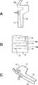
以下、この発明の一実施形態について図面を参照しながら説明する。図1Aは、この発明の一実施形態による腕時計型情報端末の正面図である。腕時計型情報端末は、本体1と、本体1の上端部および下端部に係り止めされたリストバンド2とを備える。電源としての電池は、本体1内またはリストバンド2内に収納される。 Hereinafter, an embodiment of the present invention will be described with reference to the drawings. FIG. 1A is a front view of a wristwatch-type information terminal according to an embodiment of the present invention. The wristwatch-type information terminal includes a
本体1の略中央には、フラットディスプレイ例えばLCD(Liquid Crystal Display)
等の表示部3が配置されている。そして、本体1の右上部には、CCD(Charge Coupled Device)、CMOS(Complementary Metal Oxide Semiconductor)等の撮像素子とレンズ
とからなるカメラ部4が設けられている。本体1の筐体は、セラミック、プラスチック等の非導電性材料からなる。At the approximate center of the
And the like. In the upper right portion of the
本体1の表示部3の周囲の正面または本体1の上、下、左または右側面の筐体表面がユーザの情報入力面とされる。一実施形態においては、本体1の一方の側面であって、表示部3の側面と重なり合う高さの領域がこの発明による入力装置の情報入力面5とされる。後述するように、情報入力面5の側面筐体の内側には位置センサー、例えば、静電容量の変化を検知する静電センサー(以下、適宜センサーと称する)が設置されている。 The front surface around the
図1Bに示すように、情報入力面5に対して、ユーザの指例えば人指し指の指先6が接触しながら上下に移動することで入力操作がなされる。指先6の位置が内側のセンサーによって検出される。後述するように、指先6が上下に動くことによって、表示部3において、選択位置またはカーソルが上下される。 As shown in FIG. 1B, an input operation is performed by moving the
また、図1Cに示すように、情報入力面5を高さ方向に3分割したタップ位置U、C、Lが規定される。これらのタップ位置を上タップ位置U、中タップ位置C、下タップ位置Lと呼ぶことにする。各タップ位置を1回軽く打つことによって、指先6の離間・接触がセンサーによって検知され、タップ動作が認識される。タップ動作は、選択されている位置のメニューの決定、シャッター動作等の意味を有し、タップ位置の相違がセンサーによって検出可能である。また、短時間で2回のタップを行うことをタップ動作と定義しても良い。 Further, as shown in FIG. 1C, tap positions U, C, and L obtained by dividing the
図2は、本体の裏側の筐体を取り外した状態を概略的に示す。本体1の箱型の収納部には、表示部3、カメラ部4、図示しない信号処理用のICが実装された回路基板等が収納されると共に、情報入力面5の側面に沿ってセンサー10のセンシング部が配置されている。裏側の筐体と回路基板(図示しない)との間の隙間にセンサー10が取り付けられる。センサー10は、軽量且つ薄型のフィルム状であるので、例えば両面接着テープにより取り付けることができる。 FIG. 2 schematically shows a state in which a housing on the back side of the main body is removed. The
図3を参照してセンサー10の一例について説明する。センサー10は、図3Aに示すように、基部11と、基部11から延長する帯状部12とがポリイミド等からなるフレキシブル配線基板によって一体として構成されている。図3Aは、操作面から見た図であって、反対側の面が部品面とされている。 An example of the
基部11の部品面に信号処理用IC、水晶発振器、抵抗、コンデンサ等のチップ部品が実装されている。帯状部12の部品面に電極パターンが形成される。例えばICがASIC(Application Specific Integrated Circuit)とされ、ベアチップを使用したフリップ
チップ実装を行うことによって、センサー10の小型化と薄型化が実現されている。Chip components such as a signal processing IC, a crystal oscillator, a resistor, and a capacitor are mounted on the component surface of the
帯状部12の略中央位置に本体1の上下方向の湾曲に沿った線上に多数の小穴13が形成されている。小穴13によって、図3Cに示すように、小穴13の形成されている線に沿って帯状部12を部品面側にほぼ直角に折り曲げることが容易とされている。小穴に代えてスリット、溝等を設けて折り曲げを容易としても良い。さらに、フレキシブルな特性を利用して本体1内に丸めて収納するようにしても良い。 A large number of
帯状部12の基部11から離れた側の折り曲げ部がセンシング部14である。センシング部14の部品面には、図3Bに拡大して示すように、櫛歯状に電極が形成されている。すなわち、共通電極15がセンシング部14の延長方向に一定の間隔が形成され、二つの共通電極の間の中央に位置するように、検出電極16a、16b、・・・・が形成されている。センシング部14は、帯状部12の延長方向の位置を検知する1次元位置センサーの構成とされている。 The bent portion on the side away from the
上述したセンサー10が図2に示すように、本体1内に収納され、センシング部14が本体1の側面の情報入力面5と対向される。情報入力面5とセンシング部14の間に筐体が介在するが、筐体の厚みが1mm程度であるので、情報入力面5上の指先6の位置、並びに指先6のタップ動作をセンサー10が検知することができる。 As shown in FIG. 2, the
センサー10のセンシング部14では、隣接する電極間に静電容量が形成され、この静電容量が指先6の接近によって変化することを検出して1次元方向の座標位置を検出するようになされる。すなわち、指先6が導電性を有しているので、電極間で発生する電気力線が指先で吸収され、その結果、静電容量が変化する。したがって、金属物等を手に持って操作した場合のように、指以外の物で操作面上に部分的に容量変化を起こした場合でも、同様に位置検出が可能であるが、導電性のない物(爪、ペン等)では、位置検出がされない。このようなセンサー10は、ノート型パーソナルコンピュータで使用されている2次元のポインティングデバイス(タッチパッドまたはトラックパッドと称される)と同様の動作原理のものである。 In the
図4は、この発明の一実施形態による情報端末装置のシステム構成の一例を示す。図4に示すように、この情報端末装置は、装置全体を制御するCPU(Central Processing Unit) 21を有する。CPU21は、プログラムに基づき、各部を制御する。 FIG. 4 shows an example of a system configuration of the information terminal device according to one embodiment of the present invention. As shown in FIG. 4, the information terminal device has a CPU (Central Processing Unit) 21 for controlling the entire device. The
CPU21に対して、表示部3、カメラ部4およびセンサー10が接続されている。表示部3には、情報端末装置を制御するためのメニューが表示され、また、カメラ部4によって撮影された画像が表示可能とされている。さらに、CPU21に対してプログラム格納用および作業用のメモリ22、外部ストレージ23および無線装置24が接続される。外部ストレージ23は、例えばリムーバブルなメモリカードである。 The
無線装置24は、Bluetooth方式、IrDA(Infrared Data Association)方式等の近距離通信、無線LAN(Local Area Network)の通信、PHS(Personal Handyphone System)等の公衆無線を行うための装置である。情報端末装置に対して例えばIPアドレスが割り当てられている。無線装置24によって、他のパーソナルコンピュータと通信したり、屋外のアクセスポイントとの通信が可能とされ、コマンド、データ等を無線通信で送受信できる。なお、参照符号25は、バッテリー、安定化回路等からなる電源部である。 The
図5は、この発明の一実施形態による腕時計型情報端末の操作方法を説明するための図である。この一実施形態による腕時計型情報端末の動作モードの切替は、スクロールおよびタップにより行われる。スクロールは、図5Aに示すように、腕時計型情報端末の本体1の側面の情報入力面5を上方向あるいは下方向に指先でなぞる操作である。なお、以下では、情報入力面5を下方向になぞる操作を下スクロールと称し、情報入力面5を上方向になぞる操作を上スクロールと称する。タップは、情報入力面5を軽く叩く操作であり、操作位置に応じて異なるタップとして認識される。ここでは、図5Bに示すように、図の上から下に向かって、上タップU、中タップC、下タップLが規定されている。 FIG. 5 is a diagram for explaining a method of operating the wristwatch-type information terminal according to the embodiment of the present invention. Switching of the operation mode of the wristwatch-type information terminal according to this embodiment is performed by scrolling and tapping. As shown in FIG. 5A, scrolling is an operation of tracing the
図6を参照して、この発明の一実施形態による情報端末装置の操作の一例を説明する。一実施形態においては、カメラモード、スケジューラモード、電子メールモード等の複数の動作モードが可能とされている。ここで、カメラモードは、所望の被写体を撮影するためのディジタルカメラとしての動作モードであり、スケジューラーモードは個人のスケジュールなどを管理するためのモードであり、メールモードは無線などを介してパーソナルコンピュータからメールを受信するためのモードである。各モードでは、表示部3にモード名が表示される。最初に、ユーザがモード選択動作を行う。 An example of the operation of the information terminal device according to the embodiment of the present invention will be described with reference to FIG. In one embodiment, a plurality of operation modes such as a camera mode, a scheduler mode, and an e-mail mode are allowed. Here, the camera mode is an operation mode as a digital camera for photographing a desired subject, the scheduler mode is a mode for managing personal schedules and the like, and the mail mode is a personal computer via a radio or the like. This is the mode for receiving mail from. In each mode, the
図6に示すように、情報入力面5を指先で上下になぞるスクロールを行うと、カメラモード表示31a 、スケジューラモード表示31b、電子メールモード表示31c・・・
が切り換えられる。ユーザは、所望のモード表示の状態で、中タップをタップする。それによってモード選択がなされる。As shown in FIG. 6, when the user scrolls up and down the
Is switched. The user taps the middle tap in a desired mode display state. Thereby, mode selection is performed.
一例として、カメラモード表示31aが表示部3になされている状態で、中タップをタップすることによって、カメラモードが選択される。カメラモードの動作を図6を参照して説明する。中タップをタップすることによって、カメラモードのメニュー表示画面32aが表示される。メニューとしては、撮影メニュー、再生メニュー、消去メニュー、戻り(Back)とがある。選択されているメニューがハイライト表示、反転表示等のカーソルで指示される。メニュー表示画面32aでは、撮影メニューが選択されている。 As an example, the camera mode is selected by tapping the middle tap while the
この状態から下スクロールを行うことによってカーソルが下方向に移動し、再生メニューが選択されている画面32b、消去メニューが選択されている画面32cが順に表示され、さらに、下スクロールを行うことによって、戻りが選択されている画面32dが表示される。各メニューが選択されているメニュー表示画面32a,32b,32c,32dにおいて、中タップをタップすることによって実行されるメニューが決定される。また、画面32dにおいて、中タップをタップすることによって、メニュー表示画面32dからカメラモード表示31aに戻る。 By performing a downward scroll from this state, the cursor moves downward, and a
カメラモードにおける各メニューについて説明する。メニュー表示画面32aが表示されている状態で中タップがタップされると、撮影メニューが選択される。そして、カメラ部4により撮影される画像が表示される画像表示画面331が表示される。撮影メニュー
であることが画面内のシャッターボタン33aの表示の色を変えることによってユーザに示される。画像表示画面331を確認したら、中タップをタップする。これにより、画像
表示画面332に表示された被写体が撮影される。撮影終了後に、中タップをタップする
と、撮影された画像が所定時間例えば3秒間表示される。そして、中タップをタップする毎に、シャッターボタン33aが押されることになり、画像が撮影される。参照符号33bは、撮影可能な画像の残枚数を示す残枚数表示である。Each menu in the camera mode will be described. When the middle tap is tapped while the
カメラ部4によって撮影された画像は、必要に応じて圧縮されてから外部ストレージ23に記憶される。撮影された画像を再生する場合には、外部ストレージ23から画像データが読み出され、圧縮されている場合には、伸長されてから表示部3に表示される。なお、撮影画像は、外部ストレージに限らず、内部のフラッシュメモリに格納しても良い。 The image captured by the
撮影メニューを終了する時には、画像表示画面332等の画像表示画面が選択されてい
る状態で、下スクロールを行い、表示画面333で示すように、“Back”ボタンを選
択し、中タップをタップする。この中タップによって、撮影メニューが終了する。そして、メニュー画面32dが表示される状態となる。When exit the shooting menu, in a state where the
メニュー画面32bに示すように、再生メニューを選択し、中タップをタップした場合には、再生メニューが実行される。再生メニューでは、表示画面341で示すように、再
生画像と、画像インデックス34aと、順送りボタン34bとが表示される。画像インデックス34aは、全撮影枚数中のうち、何枚目が表示されているかを示す表示である。順送りボタン34bは、撮影画像を1枚ずつ順に表示するためのボタンである。表示画面341において、中タップをタップすると、次の撮影画像の表示画面342が表示される。その後、中タップをタップする毎に、撮影画面が1枚ずつ順送りされる。As shown in the
再生メニューを終了する時には、画像表示画面342等の再生画像の表示画面が選択さ
れている状態で、下スクロールを行い、表示画面343で示すように、“Back”ボタ
ンを選択し、中タップをタップする。この中タップによって、再生メニューが終了する。そして、メニュー画面32dが表示される状態となる。When exit the playback menu, in a state where the display screen of the image display screen 342, etc. of the playback image is selected, performs a down scroll, as shown by the display screen 343, select "Back" button, medium Tap the tap. The playback menu is ended by tapping on this. Then, the
メニュー画面32cに示すように、消去メニューを選択し、中タップをタップした場合には、消去メニューが実行される。消去メニューでは、表示画面351で示すように、再
生画像と、画像インデックス35aと、消去ボタン35bとが表示される。画像インデックス35aは、全撮影枚数中のうち、何枚目が表示されているかを示す表示である。表示画面351において、中タップをタップすると、消去確認画面352が表示される。消去確認画面352においては、「消去しますか?」のメッセージと、「YES」および「NO
」のボタンとが表示される。消去する場合では、「YES」のボタンが選択され、消去しない場合では、「NO」のボタンが選択される。中タップをタップすることによって選択した動作が実行される。そして、次の画像に関する消去確認画面が表示される。As shown in the menu screen 32c, when the delete menu is selected and the middle tap is tapped, the delete menu is executed. In the erase menu, as shown by display screen351, and the reproduced image, and the
Button is displayed. In the case of erasing, the “YES” button is selected, and in the case of not erasing, the “NO” button is selected. The selected operation is executed by tapping the middle tap. Then, a deletion confirmation screen for the next image is displayed.
消去メニューを終了する時には、消去確認画面352等の消去確認画面が選択されてい
る状態で、下スクロールを行い、画面353で示すように、“Back”ボタンを選択し
、中タップをタップする。この中タップによって、消去メニューが終了する。そして、メニュー画面32dが表示される状態となる。When you exit the erase menu, in a state in which the erase confirmation screen, such as erasing the
なお、メニュー画面32dの表示状態において、中タップをタップすることによって、モード表示画面31aが表示される状態に戻る。 In addition, in the display state of the
次に、この発明の他の実施形態について説明する。図7は、この発明が適用された超小型ディジタルカメラの前面および背面の外観を示すものである。例えば(幅×奥行き×高さ、最大突起部を含まない寸法)が(69.1×16.8×24)(mm)の大きさとされている。小
型であるので、指でつまむように持つことができる。電源は、薄型リチウムイオン電池である。Next, another embodiment of the present invention will be described. FIG. 7 shows front and rear appearances of a micro digital camera to which the present invention is applied. For example, (width × depth × height, dimensions not including the largest protrusion) is (69.1 × 16.8 × 24) (mm). Because it is small, it can be held by pinching it with your fingers. The power supply is a thin lithium-ion battery.
ケース前面から突出する撮影レンズ41の横に電源スイッチ42が設けられている。ケース上部には、シャッタースイッチ43が設けられている。電源スイッチ42がオフ状態であっても、シャッタースイッチ43を押すと、直ちに電源がオンして撮影できるようになされている。 A
ケース背面にLCDディスプレイ44が設けられている。LCDディスプレイ44は、例えば0.55インチのサイズである。LCDディスプレイ44には、撮影しようとする画像、メモリカード等の媒体から読み出された再生画像、メニュー、種々の動作モードを示す画像等が表示される。ケース上部には、シャッターボタン43の横に、図8の平面図にも示すように、入力装置としてのタッチパッド45が設けられている。タッチパッド45の近傍には、その両端位置と中央の位置の目安となるマーカーが設けられている。 An
図9は、タッチパッド45の部分のみを示し、図9Aがケース上面側から見た図であり、図9Bが図9Aの裏面を示す。タッチパッド45は、フレキシブルな配線基板46と、配線基板46上に一列に並んで設けられた複数例えば5個の感圧スイッチ47a,47b,47c,47d,47eと、感圧スイッチ47a〜47eを被覆する樹脂製のシート48とから構成されている。配線基板46の配線形成部が必要に応じて折り曲げられてケース内に配置される。 9 shows only a portion of the
ディジタルカメラを指でもって構えて撮影する状態で、左から順に感圧スイッチ47a〜47eが配列される。シート48の上から感圧スイッチ47a〜47eの所望のものを指で押すことができる。感圧スイッチ47a〜47eとしては、例えば押下力に応じて連続的に接点抵抗値が変化する感圧接点を有するものである。感圧スイッチ47a〜47eは、指先によってシート48を介してある程度の力を加えることによってオンする。感圧スイッチ47a〜47eのオン/オフがケース内の回路部(制御部)に伝達される。 The pressure-
図10は、ディジタルカメラの回路部の構成を示す。参照符号50が例えばCCD(Charge Coupled Device)からなる撮像部を示す。撮像部50に対して撮影レンズ41を介して被写体像が入射する。撮像部50からの撮像信号S1が信号処理部51に入力される。信号処理部51は、CDS(Correlated Double Sampling)、AGCを有する。CDSは、撮像信号S1にリセット雑音が発生する期間において、その信号レベルを所定電位にクランプすることによってノイズ成分低減する。AGCは、撮像信号S1の振幅を自動的に調整する。 FIG. 10 shows a configuration of a circuit unit of the digital camera.
さらに、信号処理部51は、撮像信号S1に対してY/C分離、ガンマ補正、ホワイトバランス等の処理を行い、マトリクス処理によってビデオ信号S2を発生する。ビデオ信号S2がA/D変換器(アナログ−ディジタル変換器)52によってディジタルビデオ信号S3に変換される。 Further, the
ディジタルビデオ信号S3がバス53に出力される。バス53は、CPU(Central Processing Unit)54に接続されたもので、バス53を介してコントロール信号、アドレス
データ、ビデオデータ等が伝送される。CPU54によってディジタルカメラ全体の動作が制御される。The digital video signal S3 is output to the
バス53に対して、システムメモリ55、不揮発性メモリ56、I/Oポート57、カードインターフェース59が接続される。システムメモリ55には、プログラム等が記憶されるROM、プログラム実行時の作業領域となるRAMが含まれる。不揮発性メモリ56には、電源オフ後でも、ディジタルカメラの動作に関する各種定数等が記憶される。 A
I/Oポート57は、操作部(シャッターボタン43およびタッチパッド45)からの操作信号をバス53を介してCPU54に伝送する。メモリカードスロット58に対してメモリカードMCが装着自在とされている。メモリカードスロット58に挿入されたメモリカードMCとCPU54との間のデータの授受がカードインターフェース59を介してなされる。 The I /
アンテナ60および送受信回路61は、GPS(Global Positioning System)を構成す
る。但し、GPSの機能は、オプションの構成とされ、必ずしも備えなくても良い。ストロボが装着自在に備えられており、参照符号62で示すストロボがストロボ制御部63によって制御される。ストロボ制御部63は、バス53を介してCPU54と接続され、制御信号S4がCPU54からストロボ制御部63に供給される。ユーザの設定に応じて、自動発光、発光オン、発光オフ等の動作がなされる。The
バス53に対してカレンダー・時計部64が接続される。カレンダー・時計部64は、撮影日時、バッテリー使用時間等を管理する。撮影日時が撮影画像に付加され、バッテリの残量時間等が演算される。 A calendar /
A/D変換器52からのディジタルビデオ信号S3が圧縮/伸張部65にて例えばJPEG(Joint Photographic Experts Group)によるデータ圧縮の処理を受ける。圧縮ビデ
オデータがフレームメモリ66に書き込まれると共に、D/A変換器(ディジタル−アナログ変換器)67を介してアナログビデオ信号がLCDディスプレイ44に供給され、撮影中の画像が表示される。The digital video signal S3 from the A /
ユーザがシャッタースイッチ43を押すと、CPU54は、ディジタルビデオ信号S3をフレームメモリ66に書き込みながらシャッタースイッチ43を押した時の画像データD1を読み出した後、バス53を介して画像データD1を圧縮/伸張部65に供給する。フレームメモリ66の出力がD/A変換器67を介してLCDディスプレイ44に供給され、表示される。 When the user presses the
圧縮/伸張部65は、フレームメモリ66から読み出された撮影画像データD1に対して例えばJPEGによる圧縮を行い、圧縮画像データD2を出力する。圧縮画像データD2は、CPU54の制御の下で、カードインターフェース59を介してメモリカードスロット58に出力され、メモリカードMCに書き込まれる。 The compression /
ユーザが操作部(タッチパッド45)を操作してモードを設定すると、CPU54がOSD部68に制御信号S6を送出し、各モードに応じたパターンの画像(所謂アイコン画像)がOSD部68から出力され、D/A変換器67を介してLCDディスプレイ44上に画像に重畳して表示される。 When the user operates the operation unit (touch pad 45) to set a mode, the
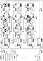
図11および図12を参照して他の実施形態におけるモード切替の一例について説明する。図11が撮影メニューの一覧の一例を示し、図12が再生メニューの一覧の一例を示す。これらのメニューは、複数の設定項目がマトリクス状に配置されたものである。各設定項目は、上位のメニュー項目毎に規定されたものである。例えば「高画質」の項目は、メニュー項目の「画質選択」の中で規定されている。メニュー項目の切替と、設定項目の切替とがタッチパッド45の異なる操作によってなされる。さらに、メニューは、タッチパッド45の両端部(感圧スイッチ47aおよび47e)を同時に押すことによってLCDディスプレイ44上に表示される。メニュー項目および設定項目の切替を行い、所望のメニューを選択し、そのメニューがLCDディスプレイ44上に表示されている状態で、タッチパッド45の両端部(感圧スイッチ47aおよび47e)が同時に押される。その結果、メニューが非表示になると同時に、複数の設定項目中で最後に表示されていた設定項目が有効とされる。 An example of mode switching in another embodiment will be described with reference to FIGS. FIG. 11 shows an example of a shooting menu list, and FIG. 12 shows an example of a playback menu list. These menus have a plurality of setting items arranged in a matrix. Each setting item is defined for each higher-level menu item. For example, the item "high image quality" is defined in the menu item "select image quality". Switching of menu items and switching of setting items are performed by different operations of the
図11に示す撮影メニューの一覧においては、矢印71で示す水平方向にメニュー項目が切り替えられ、矢印72で示す垂直方向(例えば上から下)に設定項目が切り替えられる。タッチパッド45の上を指先で左右になぞることによって、矢印71で示すようにメニュー項目が切り替えられる。タッチパッド45の中央部(中央位置の感圧スイッチ47c)を指先で押す度に設定項目が切り替えられる。 In the shooting menu list shown in FIG. 11, the menu items are switched in the horizontal direction indicated by an arrow 71, and the setting items are switched in the vertical direction (for example, from top to bottom) indicated by an arrow 72. By tracing right and left on the
例えばメニュー項目として、画質選択が選択されると、最初の設定項目として、デフォルトの項目または前回(最後)の設定項目がLCDディスプレイ44上に表示される。そのメニュー項目を変更したい場合では、タッチパッド45の中央部が押される。他のメニュー項目例えば「ホワイトバランス」のメニュー項目を設定したい場合には、指先がタッチパッド45を例えば右方向になぞる。それによって、「ホワイトバランス」のメニュー項目に移動し、デフォルトの項目または前回の設定項目が表示される。表示されたメニュー項目例えば「太陽光」を「蛍光灯」に変更したい場合では、タッチパッド45の中央部の感圧スイッチ47cが2回押される。「蛍光灯」がLCDディスプレイ44上に表示されている状態で、タッチパッド45の両端部(感圧スイッチ47aおよび47e)が同時に押される。その結果、メニューが非表示になると同時に、最後に表示されていた設定項目の「蛍光灯」が有効とされる。 For example, when the image quality selection is selected as a menu item, a default item or a previous (last) setting item is displayed on the
図13に示すように、実際には、各メニュー項目を示すことが可能なアイコン画像がLCDディスプレイ44上に表示される。図13は、「ホワイトバランス」のメニュー項目における設定項目の表示を示す。 As shown in FIG. 13, an icon image capable of indicating each menu item is actually displayed on the
オートホワイトバランスのモードが設定されると、表示75がLCDディスプレイ44に表示される。「太陽光」のモードの場合の表示76、「白熱灯」のモードの場合の表示77および「蛍光灯」の場合の表示78が用意されている。他のモードについても図示を省略するが、それぞれ表示が用意されている。 When the auto white balance mode is set, the
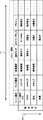
図12に示す再生メニューの一覧において、設定を変更する操作は、上述した撮影メニューの場合と同様である。タッチパッド45の上部を左右になぞることによって、矢印73で示すように、メニュー項目が切り替えられ、各メニュー項目において、中央の感圧スイッチ47cを押す毎に、メニュー項目が矢印74で示すように、上から下に順に切り替えられる。所望のメニュー項目が選択されると、デフォルトの項目または前回(最後)の設定項目がLCDディスプレイ44上に表示される。 In the reproduction menu list shown in FIG. 12, the operation of changing the setting is the same as that of the above-described shooting menu. By tracing the upper portion of the
「1枚削除」および「全画削除」は、メモリカードMC上の画像データを削除するメニュー項目である。消去動作の場合では、メニューを切り替えた後に、実際に消去動作を行うか否かのメニュー項目(「消去実行」)が設けられている。「消去実行」のメニュー項目が選択されると、消去動作が実行され、消去動作の「実行中」のアイコン等がLCDディスプレイ44上に表示される。撮影メニューの場合と同様に、所望のメニューがLCDディスプレイ44上に表示されている状態で、タッチパッド45の両端部(感圧スイッチ47aおよび47e)が同時に押される結果、メニューが非表示になると同時に、最後に表示されていた設定項目が有効とされる。 “Delete one image” and “delete all images” are menu items for deleting image data on the memory card MC. In the case of the erasing operation, a menu item ("Erase execution") for determining whether or not to actually perform the erasing operation after switching the menu is provided. When the “erase execution” menu item is selected, the erase operation is executed, and an “executing” icon or the like of the erase operation is displayed on the
図示しないが、タッチパッド45の左端の感圧スイッチ47aを長く押すと、LCDディスプレイ44上に、バッテリーの残量表示と残りの撮影可能枚数とが表示される。 Although not shown, when the pressure-
この発明は、上述したこの発明の一実施形態等に限定されるものでは無く、この発明の要旨を逸脱しない範囲内で様々な変形や応用が可能である。例えばこの発明は、静電容量型の位置センサー、感圧スイッチ以外の指の位置を検出できるセンサー例えば指先が触れるとオンするタッチスイッチを使用できる。また、この発明は、腕時計型の構成に限らず、ネックレス、指輪、腕輪等のウエアラブル(身体装着可能)な情報端末装置に対して適用することができる。さらに、PDA型あるいは携帯電話型の情報端末装置にこの発明を適用するようにしてもよい。 The present invention is not limited to the above-described embodiment of the present invention, and various modifications and applications are possible without departing from the gist of the present invention. For example, the present invention can use a capacitance type position sensor, a sensor capable of detecting the position of a finger other than the pressure-sensitive switch, for example, a touch switch that is turned on when a fingertip touches. Further, the present invention is not limited to a wristwatch-type configuration, and can be applied to a wearable (body-wearable) information terminal device such as a necklace, a ring, and a bracelet. Further, the present invention may be applied to a PDA type or mobile phone type information terminal device.
1・・・本体
3・・・表示部
4・・・カメラ部
5・・・情報入力面
6・・・指先
10・・・センサー
14・・・センシング部
41・・・撮影レンズ
43・・・シャッタースイッチ
44・・・LCDディスプレイ
45・・・タッチパッド
47a〜47e・・・感圧スイッチ
DESCRIPTION OF
Claims (23)
Translated fromJapanese上記位置センサーに接触する指の位置と、上記指の接触・離間とを上記位置センサーによって検出し、
上記指の位置と上記指の接触・離間操作とに対応する操作信号を情報端末装置を制御するコントローラに対して供給するようにした入力装置。A position sensor is arranged on a part of the outer surface of the main body of the information terminal device,
The position of the finger in contact with the position sensor and the contact / separation of the finger are detected by the position sensor,
An input device configured to supply an operation signal corresponding to the position of the finger and a contact / separation operation of the finger to a controller that controls the information terminal device.
上記センシング部を覆う筐体表面に接触する指の位置と、上記筐体表面における上記指の接触・離間とを上記位置センサーによって検出し、
上記指の位置と上記指の接触・離間操作とに対応する操作信号を情報端末装置を制御するコントローラに対して供給するようにした入力装置。The sensing part of the position sensor is covered by the housing of the main body of the information terminal device,
The position of the finger that contacts the surface of the housing that covers the sensing unit, and the contact / separation of the finger on the surface of the housing is detected by the position sensor,
An input device configured to supply an operation signal corresponding to the position of the finger and a contact / separation operation of the finger to a controller that controls the information terminal device.
上記指を接触させた状態で、上記筐体表面において指を移動させることによって選択位置を変更するようにした入力装置。In claim 2,
An input device in which a selected position is changed by moving a finger on the surface of the housing in a state where the finger is in contact with the input device.
上記指を接触・離間させることによって、決定入力を行うようにした入力装置。In claim 2,
An input device for performing a determination input by touching and separating the finger.
上記本体に表示部が設けられた入力装置。In claim 2,
An input device provided with a display unit on the main body.
上記接触・離間の位置が上記筐体表面における所定の場所とされた入力装置。In claim 2,
The input device, wherein the contact / separation position is a predetermined position on the surface of the housing.
上記筐体が、非導電性材料からなる入力装置。In claim 2,
An input device in which the housing is made of a non-conductive material.
上記非導電性材料がセラミックあるいはプラスチックである入力装置。In claim 8,
An input device wherein the non-conductive material is ceramic or plastic.
上記位置センサーは、上記センシング部がフィルム状の構成とされ、上記指の接触によって生じる静電容量の変化を検知するようになされた入力装置。In claim 1 or 2,
The position sensor is an input device in which the sensing unit has a film-like configuration, and detects a change in capacitance caused by contact of the finger.
上記位置センサーは、指の接触によってオンする複数の感圧スイッチが少なくとも一方向に整列して配された入力装置。In claim 1 or 2,
The input device, wherein the position sensor includes a plurality of pressure-sensitive switches that are turned on by a touch of a finger and arranged in at least one direction.
上記入力装置は、
本体の外面の一部に位置センサーが配置され、
上記位置センサーに接触する指の位置と、上記指の接触・離間とを上記位置センサーによって検出し、
上記指の位置と上記指の接触・離間操作とに対応する操作信号を情報端末装置を制御するコントローラに対して供給する構成とされた情報端末装置。In an information terminal device in which an input device and an operation signal from the input device are provided to a controller for control,
The input device is
A position sensor is placed on a part of the outer surface of the main unit,
The position of the finger in contact with the position sensor and the contact / separation of the finger are detected by the position sensor,
An information terminal device configured to supply an operation signal corresponding to the position of the finger and the contact / separation operation of the finger to a controller that controls the information terminal device.
上記入力装置は、
本体の筐体によって、位置センサーのセンシング部が覆われ、
上記センシング部を覆う筐体表面に接触する指の位置と、上記筐体表面における上記指の接触・離間とを上記位置センサーによって検出し、
上記指の位置と上記指の接触・離間操作とに対応する操作信号を発生する構成とされた情報端末装置。In an information terminal device in which an input device and an operation signal from the input device are provided to a controller for control,
The input device is
The housing of the main body covers the sensing part of the position sensor,
The position of the finger that contacts the surface of the housing that covers the sensing unit, and the contact / separation of the finger on the surface of the housing is detected by the position sensor,
An information terminal device configured to generate an operation signal corresponding to a position of the finger and a contact / separation operation of the finger.
上記指を接触させた状態で、上記筐体表面において指を移動させることによって選択位置を変更するようにした情報端末装置。In claim 12,
An information terminal device wherein a selected position is changed by moving a finger on the surface of the housing while the finger is in contact with the information terminal device.
上記指を接触・離間させることによって、決定入力を行うようにした情報端末装置。In claim 12,
An information terminal device configured to perform a determination input by touching and separating the finger.
上記本体に表示部が設けられた情報端末装置。In claim 12,
An information terminal device provided with a display unit on the main body.
上記接触・離間の位置が上記筐体表面における所定の場所とされた情報端末装置。In claim 12,
An information terminal device in which the contact / separation position is a predetermined location on the housing surface.
上記筐体が、非導電性材料からなる情報端末装置。In claim 12,
An information terminal device in which the housing is made of a non-conductive material.
上記非導電性材料がセラミックあるいはプラスチックである情報端末装置。In claim 17,
An information terminal device wherein the non-conductive material is ceramic or plastic.
上記位置センサーは、上記センシング部がフィルム状の構成とされ、上記指の接触によって生じる静電容量の変化を検知するようになされた情報端末装置。In claim 11 or 12,
The information terminal device, wherein the position sensor is configured such that the sensing unit has a film-like configuration and detects a change in capacitance caused by the contact of the finger.
上記位置センサーは、指の接触によってオンする複数の感圧スイッチが少なくとも一方向に整列して配された情報端末装置。In claim 11 or 12,
The information terminal device, wherein the position sensor includes a plurality of pressure-sensitive switches that are turned on by a touch of a finger and arranged in at least one direction.
位置センサー上を指でなぞることによってモード項目を切り替えるステップと、
上記位置センサー上の所定位置を指で接触・離間させることによって設定項目を切り替えるステップと、
現在のモードを示す表示をディスプレイ上に表示するステップとからなるモード切替方法。In a mode switching method for an information terminal device in which a plurality of modes are defined so as to have a setting item below the mode item,
Switching a mode item by tracing a finger on the position sensor;
Switching a setting item by contacting / separating a predetermined position on the position sensor with a finger;
Displaying a current mode display on a display.
上記モード項目を切り替えた直後のモードが前回のモードに設定されるモード切替方法。In claim 21,
A mode switching method in which the mode immediately after switching the mode item is set to the previous mode.
上記指の接触・離間を行う度にモードが変化するモード切替方法。
In claim 21,
A mode switching method in which the mode changes each time the finger is touched or separated.
Priority Applications (5)
| Application Number | Priority Date | Filing Date | Title |
|---|---|---|---|
| JP2004040742AJP2004288172A (en) | 2003-03-04 | 2004-02-18 | Input device, information terminal device and mode switching method |
| US10/547,392US7791587B2 (en) | 2003-03-04 | 2004-03-03 | Input apparatus, information terminal apparatus, and mode switching method |
| KR1020057015956AKR20050115882A (en) | 2003-03-04 | 2004-03-03 | Input device, information terminal device, and mode-switching method |
| EP04716726.7AEP1610209B1 (en) | 2003-03-04 | 2004-03-03 | Input device, information terminal device, and mode- switching method |
| PCT/JP2004/002676WO2004090705A1 (en) | 2003-03-04 | 2004-03-03 | Input device, information terminal device, and mode- switching method |
Applications Claiming Priority (2)
| Application Number | Priority Date | Filing Date | Title |
|---|---|---|---|
| JP2003056529 | 2003-03-04 | ||
| JP2004040742AJP2004288172A (en) | 2003-03-04 | 2004-02-18 | Input device, information terminal device and mode switching method |
Publications (1)
| Publication Number | Publication Date |
|---|---|
| JP2004288172Atrue JP2004288172A (en) | 2004-10-14 |
Family
ID=33161459
Family Applications (1)
| Application Number | Title | Priority Date | Filing Date |
|---|---|---|---|
| JP2004040742APendingJP2004288172A (en) | 2003-03-04 | 2004-02-18 | Input device, information terminal device and mode switching method |
Country Status (5)
| Country | Link |
|---|---|
| US (1) | US7791587B2 (en) |
| EP (1) | EP1610209B1 (en) |
| JP (1) | JP2004288172A (en) |
| KR (1) | KR20050115882A (en) |
| WO (1) | WO2004090705A1 (en) |
Cited By (22)
| Publication number | Priority date | Publication date | Assignee | Title |
|---|---|---|---|---|
| JP2006302204A (en)* | 2005-04-25 | 2006-11-02 | Chiba Inst Of Technology | Portable operation input device |
| WO2007053217A1 (en)* | 2005-10-31 | 2007-05-10 | Hewlett-Packard Development Company, L.P. | Imaging device scrolling touch pad with tap points |
| KR100899943B1 (en) | 2007-08-31 | 2009-05-28 | 에스케이 텔레콤주식회사 | Mode switching method based on vibration detection and terminal device applied thereto |
| JP2010009392A (en)* | 2008-06-27 | 2010-01-14 | Nikon Corp | Digital photo frame |
| JP2010035020A (en)* | 2008-07-30 | 2010-02-12 | Fujitsu Ltd | Mobile terminal device |
| JP2010219641A (en)* | 2009-03-13 | 2010-09-30 | Olympus Imaging Corp | Image capturing apparatus, and method for switching mode of the same |
| JP2010262463A (en)* | 2009-05-07 | 2010-11-18 | Sony Ericsson Mobile Communications Ab | Electronic apparatus, input processing method, and input device |
| JP2013150359A (en)* | 2013-04-24 | 2013-08-01 | Olympus Imaging Corp | Imaging apparatus and mode switching method therefor |
| JP2014029722A (en)* | 2013-10-03 | 2014-02-13 | Sony Mobile Communications Ab | Electronic apparatus, input processing method and input device |
| JP2014035754A (en)* | 2012-08-10 | 2014-02-24 | Nissha Printing Co Ltd | Touch sensor and electronic device |
| JP2014102839A (en)* | 2012-11-20 | 2014-06-05 | Samsung Electronics Co Ltd | Transition and interaction model for wearable electronic device |
| JP2014522071A (en)* | 2011-08-16 | 2014-08-28 | シェーファー,マーク | Watch keyboard |
| JP2015122648A (en)* | 2013-12-24 | 2015-07-02 | 京セラ株式会社 | Portable electronic devices |
| JP2015537214A (en)* | 2012-11-28 | 2015-12-24 | モントレー・ラドー・エス アー | Portable touch electronic products |
| US9477320B2 (en) | 2011-08-16 | 2016-10-25 | Argotext, Inc. | Input device |
| US10185416B2 (en) | 2012-11-20 | 2019-01-22 | Samsung Electronics Co., Ltd. | User gesture input to wearable electronic device involving movement of device |
| US10194060B2 (en) | 2012-11-20 | 2019-01-29 | Samsung Electronics Company, Ltd. | Wearable electronic device |
| US10423214B2 (en) | 2012-11-20 | 2019-09-24 | Samsung Electronics Company, Ltd | Delegating processing from wearable electronic device |
| US10551928B2 (en) | 2012-11-20 | 2020-02-04 | Samsung Electronics Company, Ltd. | GUI transitions on wearable electronic device |
| US10691332B2 (en) | 2014-02-28 | 2020-06-23 | Samsung Electronics Company, Ltd. | Text input on an interactive display |
| US11157436B2 (en) | 2012-11-20 | 2021-10-26 | Samsung Electronics Company, Ltd. | Services associated with wearable electronic device |
| US11372536B2 (en) | 2012-11-20 | 2022-06-28 | Samsung Electronics Company, Ltd. | Transition and interaction model for wearable electronic device |
Families Citing this family (56)
| Publication number | Priority date | Publication date | Assignee | Title |
|---|---|---|---|---|
| CN1858684B (en)* | 2005-04-30 | 2011-08-03 | 张苏渝 | Method of completing signal input through motion and its characteristics |
| KR101155572B1 (en)* | 2006-03-27 | 2012-06-19 | 주식회사 이노칩테크놀로지 | Pointing device and handheld terminal having the same and method for controlling the same |
| US7607243B2 (en) | 2006-05-03 | 2009-10-27 | Nike, Inc. | Athletic or other performance sensing systems |
| US20070286596A1 (en)* | 2006-06-08 | 2007-12-13 | Lonn Fredrik A | Method and system for adjusting camera settings in a camera equipped mobile radio terminal |
| US20080183313A1 (en)* | 2007-01-29 | 2008-07-31 | Johan Lundquist | System, device and method for steering a mobile terminal |
| US8370549B2 (en) | 2007-09-07 | 2013-02-05 | Nike, Inc. | Wearable device assembly having athletic functionality |
| US20090085865A1 (en)* | 2007-09-27 | 2009-04-02 | Liquivision Products, Inc. | Device for underwater use and method of controlling same |
| US8517896B2 (en) | 2008-04-02 | 2013-08-27 | Nike, Inc. | Wearable device assembly having athletic functionality |
| JP4600548B2 (en)* | 2008-08-27 | 2010-12-15 | ソニー株式会社 | REPRODUCTION DEVICE, REPRODUCTION METHOD, AND PROGRAM |
| KR101484944B1 (en)* | 2008-10-02 | 2015-01-22 | 삼성전자 주식회사 | Electronic device case and manufacturing method thereof |
| US8624836B1 (en) | 2008-10-24 | 2014-01-07 | Google Inc. | Gesture-based small device input |
| JP4692625B2 (en)* | 2008-12-26 | 2011-06-01 | ブラザー工業株式会社 | Input device |
| US8497884B2 (en) | 2009-07-20 | 2013-07-30 | Motorola Mobility Llc | Electronic device and method for manipulating graphic user interface elements |
| JP5523559B2 (en)* | 2010-05-20 | 2014-06-18 | 三菱電機株式会社 | In-vehicle information system |
| US8824245B2 (en) | 2010-10-25 | 2014-09-02 | Advance Watch Company, Ltd. | Touch screen watch |
| US9081542B2 (en)* | 2012-08-28 | 2015-07-14 | Google Technology Holdings LLC | Systems and methods for a wearable touch-sensitive device |
| US10413251B2 (en) | 2012-10-07 | 2019-09-17 | Rhythm Diagnostic Systems, Inc. | Wearable cardiac monitor |
| US9477313B2 (en) | 2012-11-20 | 2016-10-25 | Samsung Electronics Co., Ltd. | User gesture input to wearable electronic device involving outward-facing sensor of device |
| US9030446B2 (en)* | 2012-11-20 | 2015-05-12 | Samsung Electronics Co., Ltd. | Placement of optical sensor on wearable electronic device |
| EP2784606A1 (en)* | 2013-03-27 | 2014-10-01 | Montres Rado S.A. | Touch-sensitive portable electronic object |
| ITMI20122258A1 (en) | 2012-12-28 | 2014-06-29 | Rototype Spa | METHOD OF IMPLEMENTATION OF A BANK CHECK AND BANK CHECK MADE WITH SUCH A METHOD |
| US9753436B2 (en) | 2013-06-11 | 2017-09-05 | Apple Inc. | Rotary input mechanism for an electronic device |
| EP3014400B1 (en) | 2013-08-09 | 2020-06-03 | Apple Inc. | Tactile switch for an electronic device |
| TWI554852B (en)* | 2014-01-22 | 2016-10-21 | 巨擘科技股份有限公司 | Time adjusting method and system for wristwatch |
| US10048802B2 (en) | 2014-02-12 | 2018-08-14 | Apple Inc. | Rejection of false turns of rotary inputs for electronic devices |
| KR20250021617A (en) | 2014-09-02 | 2025-02-13 | 애플 인크. | Wearable electronic device |
| US9785123B2 (en)* | 2014-09-26 | 2017-10-10 | Intel Corporation | Digital analog display with rotating bezel |
| CN105988361A (en)* | 2015-02-10 | 2016-10-05 | 阿里巴巴集团控股有限公司 | Control method of intelligent watch and apparatus thereof, and the intelligent watch |
| EP3251139B1 (en) | 2015-03-08 | 2021-04-28 | Apple Inc. | Compressible seal for rotatable and translatable input mechanisms |
| KR101639338B1 (en)* | 2015-04-30 | 2016-07-13 | 성균관대학교산학협력단 | Method and smart watch device for providing input-interface using recognizing tapping |
| CN104865823A (en)* | 2015-06-16 | 2015-08-26 | 深圳市欧珀通信软件有限公司 | Smartwatch |
| CN104994258A (en)* | 2015-06-16 | 2015-10-21 | 成都西可科技有限公司 | Equipment for achieving video and picture shooting of outdoor sports |
| KR102465377B1 (en)* | 2016-02-12 | 2022-11-10 | 삼성디스플레이 주식회사 | Display device and the method of manufacturing thereof |
| US10551798B1 (en) | 2016-05-17 | 2020-02-04 | Apple Inc. | Rotatable crown for an electronic device |
| US10061399B2 (en) | 2016-07-15 | 2018-08-28 | Apple Inc. | Capacitive gap sensor ring for an input device |
| US10019097B2 (en) | 2016-07-25 | 2018-07-10 | Apple Inc. | Force-detecting input structure |
| DE102016216126A1 (en) | 2016-08-26 | 2018-03-01 | Dometic Sweden Ab | Cooling device for a recreational vehicle |
| CN108319127A (en)* | 2017-01-16 | 2018-07-24 | 深圳智能表芯科技有限公司 | A kind of key control method and device of smartwatch |
| US10962935B1 (en) | 2017-07-18 | 2021-03-30 | Apple Inc. | Tri-axis force sensor |
| US11360440B2 (en) | 2018-06-25 | 2022-06-14 | Apple Inc. | Crown for an electronic watch |
| WO2020021522A1 (en)* | 2018-07-26 | 2020-01-30 | Yoav Netzer | Wrist camera activation |
| US11561515B2 (en) | 2018-08-02 | 2023-01-24 | Apple Inc. | Crown for an electronic watch |
| US12259690B2 (en) | 2018-08-24 | 2025-03-25 | Apple Inc. | Watch crown having a conductive surface |
| CN211293787U (en) | 2018-08-24 | 2020-08-18 | 苹果公司 | Electronic watch |
| CN209625187U (en) | 2018-08-30 | 2019-11-12 | 苹果公司 | Electronic Watches and Electronic Devices |
| CN113631097A (en) | 2019-01-25 | 2021-11-09 | Rds公司 | Health monitoring system and method |
| US11194299B1 (en) | 2019-02-12 | 2021-12-07 | Apple Inc. | Variable frictional feedback device for a digital crown of an electronic watch |
| DE102019207919A1 (en) | 2019-05-29 | 2020-12-03 | Dometic Sweden Ab | Hinge mechanism, compartment door arrangement with such a hinge mechanism, cabinet or refrigerator with such a hinge mechanism and / or compartment door arrangement, and recreational vehicle |
| EP4021293A4 (en) | 2019-08-28 | 2023-08-09 | Rds | Vital signs or health monitoring systems and methods |
| US11461511B2 (en)* | 2020-03-13 | 2022-10-04 | Palo Alto Research Center Incorporated | Spatial field optimization with reduced parameters |
| US11550268B2 (en) | 2020-06-02 | 2023-01-10 | Apple Inc. | Switch module for electronic crown assembly |
| US12079386B2 (en)* | 2020-09-14 | 2024-09-03 | Zebra Technologies Corporation | Devices having protective screens selectively positionable to switch devices between user interface modes and methods of operating the same |
| US12092996B2 (en) | 2021-07-16 | 2024-09-17 | Apple Inc. | Laser-based rotation sensor for a crown of an electronic watch |
| US11868553B2 (en)* | 2022-03-11 | 2024-01-09 | Meta Platforms Technologies, Llc | Pressure sensing for user interactions |
| US12189347B2 (en) | 2022-06-14 | 2025-01-07 | Apple Inc. | Rotation sensor for a crown of an electronic watch |
| CN117666859A (en)* | 2022-08-23 | 2024-03-08 | 脸萌有限公司 | Information display method, device, electronic equipment and storage medium |
Family Cites Families (16)
| Publication number | Priority date | Publication date | Assignee | Title |
|---|---|---|---|---|
| JPH0944285A (en) | 1995-07-28 | 1997-02-14 | Hitachi Ltd | Information processing device |
| US5995083A (en) | 1996-11-20 | 1999-11-30 | Alps Electric Co., Ltd. | Coordinates input apparatus |
| JPH10198502A (en) | 1997-01-07 | 1998-07-31 | Matsushita Electric Ind Co Ltd | Coordinate position input device |
| JPH11194872A (en) | 1998-01-06 | 1999-07-21 | Poseidon Technical Systems:Kk | Contact operation type input device and its electronic part |
| JPH11194863A (en) | 1998-01-06 | 1999-07-21 | Poseidon Technical Systems:Kk | Touch input detecting method and touch input detector |
| JP2001100907A (en)* | 1999-09-30 | 2001-04-13 | Mitsumi Electric Co Ltd | Information input device |
| JP3814117B2 (en) | 2000-02-03 | 2006-08-23 | セイコーインスツル株式会社 | Electronic devices and electronic watches with composite switches |
| JP3785902B2 (en)* | 2000-07-11 | 2006-06-14 | インターナショナル・ビジネス・マシーンズ・コーポレーション | Device, device control method, pointer movement method |
| JP2002125039A (en) | 2000-10-16 | 2002-04-26 | Casio Comput Co Ltd | Communication systems and body-worn wireless communication terminals. |
| US7170488B2 (en)* | 2000-12-22 | 2007-01-30 | Logitech Europe S.A. | Pointing device with solid-state roller |
| JP3613177B2 (en) | 2000-12-26 | 2005-01-26 | インターナショナル・ビジネス・マシーンズ・コーポレーション | Input object selection apparatus and method |
| US7088343B2 (en)* | 2001-04-30 | 2006-08-08 | Lenovo (Singapore) Pte., Ltd. | Edge touchpad input device |
| JP2002333951A (en) | 2001-05-08 | 2002-11-22 | Matsushita Electric Ind Co Ltd | Input device |
| JP4127982B2 (en)* | 2001-05-28 | 2008-07-30 | 富士フイルム株式会社 | Portable electronic devices |
| CN103440040B (en)* | 2001-11-01 | 2018-02-16 | 意美森公司 | Method and apparatus for providing sense of touch |
| US20060232557A1 (en)* | 2001-12-11 | 2006-10-19 | Wolfgang Fallot-Burghardt | Combination consisting of a computer keyboard and mouse control device |
- 2004
- 2004-02-18JPJP2004040742Apatent/JP2004288172A/enactivePending
- 2004-03-03KRKR1020057015956Apatent/KR20050115882A/ennot_activeCeased
- 2004-03-03WOPCT/JP2004/002676patent/WO2004090705A1/enactiveApplication Filing
- 2004-03-03EPEP04716726.7Apatent/EP1610209B1/ennot_activeExpired - Lifetime
- 2004-03-03USUS10/547,392patent/US7791587B2/ennot_activeExpired - Fee Related
Cited By (24)
| Publication number | Priority date | Publication date | Assignee | Title |
|---|---|---|---|---|
| JP2006302204A (en)* | 2005-04-25 | 2006-11-02 | Chiba Inst Of Technology | Portable operation input device |
| WO2007053217A1 (en)* | 2005-10-31 | 2007-05-10 | Hewlett-Packard Development Company, L.P. | Imaging device scrolling touch pad with tap points |
| KR100899943B1 (en) | 2007-08-31 | 2009-05-28 | 에스케이 텔레콤주식회사 | Mode switching method based on vibration detection and terminal device applied thereto |
| JP2010009392A (en)* | 2008-06-27 | 2010-01-14 | Nikon Corp | Digital photo frame |
| JP2010035020A (en)* | 2008-07-30 | 2010-02-12 | Fujitsu Ltd | Mobile terminal device |
| JP2010219641A (en)* | 2009-03-13 | 2010-09-30 | Olympus Imaging Corp | Image capturing apparatus, and method for switching mode of the same |
| JP2010262463A (en)* | 2009-05-07 | 2010-11-18 | Sony Ericsson Mobile Communications Ab | Electronic apparatus, input processing method, and input device |
| JP2014522071A (en)* | 2011-08-16 | 2014-08-28 | シェーファー,マーク | Watch keyboard |
| JP2017050020A (en)* | 2011-08-16 | 2017-03-09 | シェーファー, マークSCHAFFER, Mark | Wrist watch keyboard |
| US9477320B2 (en) | 2011-08-16 | 2016-10-25 | Argotext, Inc. | Input device |
| JP2014035754A (en)* | 2012-08-10 | 2014-02-24 | Nissha Printing Co Ltd | Touch sensor and electronic device |
| US10423214B2 (en) | 2012-11-20 | 2019-09-24 | Samsung Electronics Company, Ltd | Delegating processing from wearable electronic device |
| JP2014102839A (en)* | 2012-11-20 | 2014-06-05 | Samsung Electronics Co Ltd | Transition and interaction model for wearable electronic device |
| US10185416B2 (en) | 2012-11-20 | 2019-01-22 | Samsung Electronics Co., Ltd. | User gesture input to wearable electronic device involving movement of device |
| US10194060B2 (en) | 2012-11-20 | 2019-01-29 | Samsung Electronics Company, Ltd. | Wearable electronic device |
| US10551928B2 (en) | 2012-11-20 | 2020-02-04 | Samsung Electronics Company, Ltd. | GUI transitions on wearable electronic device |
| US11157436B2 (en) | 2012-11-20 | 2021-10-26 | Samsung Electronics Company, Ltd. | Services associated with wearable electronic device |
| US11237719B2 (en) | 2012-11-20 | 2022-02-01 | Samsung Electronics Company, Ltd. | Controlling remote electronic device with wearable electronic device |
| US11372536B2 (en) | 2012-11-20 | 2022-06-28 | Samsung Electronics Company, Ltd. | Transition and interaction model for wearable electronic device |
| JP2015537214A (en)* | 2012-11-28 | 2015-12-24 | モントレー・ラドー・エス アー | Portable touch electronic products |
| JP2013150359A (en)* | 2013-04-24 | 2013-08-01 | Olympus Imaging Corp | Imaging apparatus and mode switching method therefor |
| JP2014029722A (en)* | 2013-10-03 | 2014-02-13 | Sony Mobile Communications Ab | Electronic apparatus, input processing method and input device |
| JP2015122648A (en)* | 2013-12-24 | 2015-07-02 | 京セラ株式会社 | Portable electronic devices |
| US10691332B2 (en) | 2014-02-28 | 2020-06-23 | Samsung Electronics Company, Ltd. | Text input on an interactive display |
Also Published As
| Publication number | Publication date |
|---|---|
| KR20050115882A (en) | 2005-12-08 |
| EP1610209A4 (en) | 2011-12-07 |
| EP1610209B1 (en) | 2019-05-08 |
| EP1610209A1 (en) | 2005-12-28 |
| US20060170649A1 (en) | 2006-08-03 |
| US7791587B2 (en) | 2010-09-07 |
| WO2004090705A1 (en) | 2004-10-21 |
Similar Documents
| Publication | Publication Date | Title |
|---|---|---|
| JP2004288172A (en) | Input device, information terminal device and mode switching method | |
| JP4897596B2 (en) | INPUT DEVICE, STORAGE MEDIUM, INFORMATION INPUT METHOD, AND ELECTRONIC DEVICE | |
| US10684766B2 (en) | Mobile terminal and method for controlling the same | |
| US9658767B2 (en) | Information processing device | |
| JP5722642B2 (en) | Mobile terminal device | |
| US9519382B2 (en) | Touch panel device and portable information terminal including touch panel device | |
| US9538086B2 (en) | Method of performing previewing and electronic device for implementing the same | |
| US20110074671A1 (en) | Image display apparatus and control method thereof, and computer program | |
| US20080079837A1 (en) | Focusing Area Adjusting Camera-Carrying Portable Terminal | |
| KR20160000793A (en) | Mobile terminal and method for controlling the same | |
| JP2014052852A (en) | Information processor | |
| JP6940353B2 (en) | Electronics | |
| US11012625B2 (en) | Electronic equipment having a touch operating face | |
| US9204045B2 (en) | Image capture method and portable communication device | |
| JP2007505584A (en) | Keypad for portable electronic devices | |
| JP2010245843A (en) | Image display device | |
| CN100483320C (en) | Input unit, mobile terminal unit, and content data manipulation method | |
| CN110661944B (en) | Electronic device | |
| CN110661941B (en) | Electronic device | |
| CN110661942B (en) | Electronic device | |
| JP5656107B2 (en) | Input device, input method, and program | |
| KR20160000795A (en) | Mobile terminal and method for controlling the same | |
| JP2003036141A (en) | Input device | |
| KR20160000796A (en) | Mobile terminal and method for controlling the same | |
| JP2012238267A (en) | Processor, processing method, and program |
Legal Events
| Date | Code | Title | Description |
|---|---|---|---|
| A131 | Notification of reasons for refusal | Free format text:JAPANESE INTERMEDIATE CODE: A131 Effective date:20060919 | |
| A521 | Request for written amendment filed | Free format text:JAPANESE INTERMEDIATE CODE: A523 Effective date:20061117 | |
| A02 | Decision of refusal | Free format text:JAPANESE INTERMEDIATE CODE: A02 Effective date:20071002 | |
| A521 | Request for written amendment filed | Free format text:JAPANESE INTERMEDIATE CODE: A523 Effective date:20071203 | |
| A521 | Request for written amendment filed | Free format text:JAPANESE INTERMEDIATE CODE: A523 Effective date:20080109 | |
| A911 | Transfer to examiner for re-examination before appeal (zenchi) | Free format text:JAPANESE INTERMEDIATE CODE: A911 Effective date:20080115 | |
| A912 | Re-examination (zenchi) completed and case transferred to appeal board | Free format text:JAPANESE INTERMEDIATE CODE: A912 Effective date:20080307 |