JP2004281514A - Wire bonding method - Google Patents
Wire bonding methodDownload PDFInfo
- Publication number
- JP2004281514A JP2004281514AJP2003067959AJP2003067959AJP2004281514AJP 2004281514 AJP2004281514 AJP 2004281514AJP 2003067959 AJP2003067959 AJP 2003067959AJP 2003067959 AJP2003067959 AJP 2003067959AJP 2004281514 AJP2004281514 AJP 2004281514A
- Authority
- JP
- Japan
- Prior art keywords
- wire
- nozzle
- cut
- pad
- bonding
- Prior art date
- Legal status (The legal status is an assumption and is not a legal conclusion. Google has not performed a legal analysis and makes no representation as to the accuracy of the status listed.)
- Granted
Links
- 238000000034methodMethods0.000titleclaimsabstractdescription21
- 238000005520cutting processMethods0.000claimsabstractdescription18
- 230000001678irradiating effectEffects0.000abstractdescription7
- 239000012141concentrateSubstances0.000description3
- 239000004065semiconductorSubstances0.000description3
- XEEYBQQBJWHFJM-UHFFFAOYSA-NIronChemical compound[Fe]XEEYBQQBJWHFJM-UHFFFAOYSA-N0.000description2
- 239000010949copperSubstances0.000description2
- 238000010586diagramMethods0.000description2
- 239000010931goldSubstances0.000description2
- 229910001369BrassInorganic materials0.000description1
- RYGMFSIKBFXOCR-UHFFFAOYSA-NCopperChemical compound[Cu]RYGMFSIKBFXOCR-UHFFFAOYSA-N0.000description1
- 229910052782aluminiumInorganic materials0.000description1
- XAGFODPZIPBFFR-UHFFFAOYSA-NaluminiumChemical compound[Al]XAGFODPZIPBFFR-UHFFFAOYSA-N0.000description1
- 239000010951brassSubstances0.000description1
- 239000000919ceramicSubstances0.000description1
- 229910052802copperInorganic materials0.000description1
- 230000003247decreasing effectEffects0.000description1
- PCHJSUWPFVWCPO-UHFFFAOYSA-NgoldChemical compound[Au]PCHJSUWPFVWCPO-UHFFFAOYSA-N0.000description1
- 229910052737goldInorganic materials0.000description1
- 230000017525heat dissipationEffects0.000description1
- 230000002452interceptive effectEffects0.000description1
- 229910052742ironInorganic materials0.000description1
- 239000002184metalSubstances0.000description1
- 229910052751metalInorganic materials0.000description1
- 238000000465mouldingMethods0.000description1
- 230000005855radiationEffects0.000description1
- 239000011347resinSubstances0.000description1
- 229920005989resinPolymers0.000description1
- 238000005476solderingMethods0.000description1
- 239000000758substrateSubstances0.000description1
- 238000003466weldingMethods0.000description1
Images

Classifications
- H—ELECTRICITY
- H01—ELECTRIC ELEMENTS
- H01L—SEMICONDUCTOR DEVICES NOT COVERED BY CLASS H10
- H01L24/00—Arrangements for connecting or disconnecting semiconductor or solid-state bodies; Methods or apparatus related thereto
- H01L24/74—Apparatus for manufacturing arrangements for connecting or disconnecting semiconductor or solid-state bodies
- H01L24/78—Apparatus for connecting with wire connectors
- H—ELECTRICITY
- H01—ELECTRIC ELEMENTS
- H01L—SEMICONDUCTOR DEVICES NOT COVERED BY CLASS H10
- H01L2224/00—Indexing scheme for arrangements for connecting or disconnecting semiconductor or solid-state bodies and methods related thereto as covered by H01L24/00
- H01L2224/01—Means for bonding being attached to, or being formed on, the surface to be connected, e.g. chip-to-package, die-attach, "first-level" interconnects; Manufacturing methods related thereto
- H01L2224/42—Wire connectors; Manufacturing methods related thereto
- H01L2224/44—Structure, shape, material or disposition of the wire connectors prior to the connecting process
- H01L2224/45—Structure, shape, material or disposition of the wire connectors prior to the connecting process of an individual wire connector
- H01L2224/45001—Core members of the connector
- H01L2224/45099—Material
- H01L2224/451—Material with a principal constituent of the material being a metal or a metalloid, e.g. boron (B), silicon (Si), germanium (Ge), arsenic (As), antimony (Sb), tellurium (Te) and polonium (Po), and alloys thereof
- H01L2224/45117—Material with a principal constituent of the material being a metal or a metalloid, e.g. boron (B), silicon (Si), germanium (Ge), arsenic (As), antimony (Sb), tellurium (Te) and polonium (Po), and alloys thereof the principal constituent melting at a temperature of greater than or equal to 400°C and less than 950°C
- H01L2224/45124—Aluminium (Al) as principal constituent
- H—ELECTRICITY
- H01—ELECTRIC ELEMENTS
- H01L—SEMICONDUCTOR DEVICES NOT COVERED BY CLASS H10
- H01L2224/00—Indexing scheme for arrangements for connecting or disconnecting semiconductor or solid-state bodies and methods related thereto as covered by H01L24/00
- H01L2224/01—Means for bonding being attached to, or being formed on, the surface to be connected, e.g. chip-to-package, die-attach, "first-level" interconnects; Manufacturing methods related thereto
- H01L2224/42—Wire connectors; Manufacturing methods related thereto
- H01L2224/44—Structure, shape, material or disposition of the wire connectors prior to the connecting process
- H01L2224/45—Structure, shape, material or disposition of the wire connectors prior to the connecting process of an individual wire connector
- H01L2224/45001—Core members of the connector
- H01L2224/45099—Material
- H01L2224/451—Material with a principal constituent of the material being a metal or a metalloid, e.g. boron (B), silicon (Si), germanium (Ge), arsenic (As), antimony (Sb), tellurium (Te) and polonium (Po), and alloys thereof
- H01L2224/45138—Material with a principal constituent of the material being a metal or a metalloid, e.g. boron (B), silicon (Si), germanium (Ge), arsenic (As), antimony (Sb), tellurium (Te) and polonium (Po), and alloys thereof the principal constituent melting at a temperature of greater than or equal to 950°C and less than 1550°C
- H01L2224/45144—Gold (Au) as principal constituent
- H—ELECTRICITY
- H01—ELECTRIC ELEMENTS
- H01L—SEMICONDUCTOR DEVICES NOT COVERED BY CLASS H10
- H01L2224/00—Indexing scheme for arrangements for connecting or disconnecting semiconductor or solid-state bodies and methods related thereto as covered by H01L24/00
- H01L2224/01—Means for bonding being attached to, or being formed on, the surface to be connected, e.g. chip-to-package, die-attach, "first-level" interconnects; Manufacturing methods related thereto
- H01L2224/42—Wire connectors; Manufacturing methods related thereto
- H01L2224/44—Structure, shape, material or disposition of the wire connectors prior to the connecting process
- H01L2224/45—Structure, shape, material or disposition of the wire connectors prior to the connecting process of an individual wire connector
- H01L2224/45001—Core members of the connector
- H01L2224/45099—Material
- H01L2224/451—Material with a principal constituent of the material being a metal or a metalloid, e.g. boron (B), silicon (Si), germanium (Ge), arsenic (As), antimony (Sb), tellurium (Te) and polonium (Po), and alloys thereof
- H01L2224/45138—Material with a principal constituent of the material being a metal or a metalloid, e.g. boron (B), silicon (Si), germanium (Ge), arsenic (As), antimony (Sb), tellurium (Te) and polonium (Po), and alloys thereof the principal constituent melting at a temperature of greater than or equal to 950°C and less than 1550°C
- H01L2224/45147—Copper (Cu) as principal constituent
- H—ELECTRICITY
- H01—ELECTRIC ELEMENTS
- H01L—SEMICONDUCTOR DEVICES NOT COVERED BY CLASS H10
- H01L2224/00—Indexing scheme for arrangements for connecting or disconnecting semiconductor or solid-state bodies and methods related thereto as covered by H01L24/00
- H01L2224/01—Means for bonding being attached to, or being formed on, the surface to be connected, e.g. chip-to-package, die-attach, "first-level" interconnects; Manufacturing methods related thereto
- H01L2224/42—Wire connectors; Manufacturing methods related thereto
- H01L2224/47—Structure, shape, material or disposition of the wire connectors after the connecting process
- H01L2224/48—Structure, shape, material or disposition of the wire connectors after the connecting process of an individual wire connector
- H01L2224/4805—Shape
- H01L2224/4809—Loop shape
- H01L2224/48091—Arched
- H—ELECTRICITY
- H01—ELECTRIC ELEMENTS
- H01L—SEMICONDUCTOR DEVICES NOT COVERED BY CLASS H10
- H01L2224/00—Indexing scheme for arrangements for connecting or disconnecting semiconductor or solid-state bodies and methods related thereto as covered by H01L24/00
- H01L2224/01—Means for bonding being attached to, or being formed on, the surface to be connected, e.g. chip-to-package, die-attach, "first-level" interconnects; Manufacturing methods related thereto
- H01L2224/42—Wire connectors; Manufacturing methods related thereto
- H01L2224/47—Structure, shape, material or disposition of the wire connectors after the connecting process
- H01L2224/48—Structure, shape, material or disposition of the wire connectors after the connecting process of an individual wire connector
- H01L2224/481—Disposition
- H01L2224/48151—Connecting between a semiconductor or solid-state body and an item not being a semiconductor or solid-state body, e.g. chip-to-substrate, chip-to-passive
- H01L2224/48221—Connecting between a semiconductor or solid-state body and an item not being a semiconductor or solid-state body, e.g. chip-to-substrate, chip-to-passive the body and the item being stacked
- H01L2224/48245—Connecting between a semiconductor or solid-state body and an item not being a semiconductor or solid-state body, e.g. chip-to-substrate, chip-to-passive the body and the item being stacked the item being metallic
- H01L2224/48247—Connecting between a semiconductor or solid-state body and an item not being a semiconductor or solid-state body, e.g. chip-to-substrate, chip-to-passive the body and the item being stacked the item being metallic connecting the wire to a bond pad of the item
- H—ELECTRICITY
- H01—ELECTRIC ELEMENTS
- H01L—SEMICONDUCTOR DEVICES NOT COVERED BY CLASS H10
- H01L2224/00—Indexing scheme for arrangements for connecting or disconnecting semiconductor or solid-state bodies and methods related thereto as covered by H01L24/00
- H01L2224/74—Apparatus for manufacturing arrangements for connecting or disconnecting semiconductor or solid-state bodies and for methods related thereto
- H01L2224/78—Apparatus for connecting with wire connectors
- H01L2224/7825—Means for applying energy, e.g. heating means
- H01L2224/783—Means for applying energy, e.g. heating means by means of pressure
- H01L2224/78301—Capillary
- H—ELECTRICITY
- H01—ELECTRIC ELEMENTS
- H01L—SEMICONDUCTOR DEVICES NOT COVERED BY CLASS H10
- H01L2224/00—Indexing scheme for arrangements for connecting or disconnecting semiconductor or solid-state bodies and methods related thereto as covered by H01L24/00
- H01L2224/74—Apparatus for manufacturing arrangements for connecting or disconnecting semiconductor or solid-state bodies and for methods related thereto
- H01L2224/78—Apparatus for connecting with wire connectors
- H01L2224/7825—Means for applying energy, e.g. heating means
- H01L2224/783—Means for applying energy, e.g. heating means by means of pressure
- H01L2224/78313—Wedge
- H—ELECTRICITY
- H01—ELECTRIC ELEMENTS
- H01L—SEMICONDUCTOR DEVICES NOT COVERED BY CLASS H10
- H01L2224/00—Indexing scheme for arrangements for connecting or disconnecting semiconductor or solid-state bodies and methods related thereto as covered by H01L24/00
- H01L2224/80—Methods for connecting semiconductor or other solid state bodies using means for bonding being attached to, or being formed on, the surface to be connected
- H01L2224/85—Methods for connecting semiconductor or other solid state bodies using means for bonding being attached to, or being formed on, the surface to be connected using a wire connector
- H01L2224/852—Applying energy for connecting
- H01L2224/8521—Applying energy for connecting with energy being in the form of electromagnetic radiation
- H01L2224/85214—Applying energy for connecting with energy being in the form of electromagnetic radiation using a laser
- H—ELECTRICITY
- H01—ELECTRIC ELEMENTS
- H01L—SEMICONDUCTOR DEVICES NOT COVERED BY CLASS H10
- H01L2924/00—Indexing scheme for arrangements or methods for connecting or disconnecting semiconductor or solid-state bodies as covered by H01L24/00
- H01L2924/01—Chemical elements
- H01L2924/01004—Beryllium [Be]
- H—ELECTRICITY
- H01—ELECTRIC ELEMENTS
- H01L—SEMICONDUCTOR DEVICES NOT COVERED BY CLASS H10
- H01L2924/00—Indexing scheme for arrangements or methods for connecting or disconnecting semiconductor or solid-state bodies as covered by H01L24/00
- H01L2924/01—Chemical elements
- H01L2924/01005—Boron [B]
- H—ELECTRICITY
- H01—ELECTRIC ELEMENTS
- H01L—SEMICONDUCTOR DEVICES NOT COVERED BY CLASS H10
- H01L2924/00—Indexing scheme for arrangements or methods for connecting or disconnecting semiconductor or solid-state bodies as covered by H01L24/00
- H01L2924/01—Chemical elements
- H01L2924/01006—Carbon [C]
- H—ELECTRICITY
- H01—ELECTRIC ELEMENTS
- H01L—SEMICONDUCTOR DEVICES NOT COVERED BY CLASS H10
- H01L2924/00—Indexing scheme for arrangements or methods for connecting or disconnecting semiconductor or solid-state bodies as covered by H01L24/00
- H01L2924/01—Chemical elements
- H01L2924/01013—Aluminum [Al]
- H—ELECTRICITY
- H01—ELECTRIC ELEMENTS
- H01L—SEMICONDUCTOR DEVICES NOT COVERED BY CLASS H10
- H01L2924/00—Indexing scheme for arrangements or methods for connecting or disconnecting semiconductor or solid-state bodies as covered by H01L24/00
- H01L2924/01—Chemical elements
- H01L2924/01019—Potassium [K]
- H—ELECTRICITY
- H01—ELECTRIC ELEMENTS
- H01L—SEMICONDUCTOR DEVICES NOT COVERED BY CLASS H10
- H01L2924/00—Indexing scheme for arrangements or methods for connecting or disconnecting semiconductor or solid-state bodies as covered by H01L24/00
- H01L2924/01—Chemical elements
- H01L2924/01029—Copper [Cu]
- H—ELECTRICITY
- H01—ELECTRIC ELEMENTS
- H01L—SEMICONDUCTOR DEVICES NOT COVERED BY CLASS H10
- H01L2924/00—Indexing scheme for arrangements or methods for connecting or disconnecting semiconductor or solid-state bodies as covered by H01L24/00
- H01L2924/01—Chemical elements
- H01L2924/01033—Arsenic [As]
- H—ELECTRICITY
- H01—ELECTRIC ELEMENTS
- H01L—SEMICONDUCTOR DEVICES NOT COVERED BY CLASS H10
- H01L2924/00—Indexing scheme for arrangements or methods for connecting or disconnecting semiconductor or solid-state bodies as covered by H01L24/00
- H01L2924/01—Chemical elements
- H01L2924/01039—Yttrium [Y]
- H—ELECTRICITY
- H01—ELECTRIC ELEMENTS
- H01L—SEMICONDUCTOR DEVICES NOT COVERED BY CLASS H10
- H01L2924/00—Indexing scheme for arrangements or methods for connecting or disconnecting semiconductor or solid-state bodies as covered by H01L24/00
- H01L2924/01—Chemical elements
- H01L2924/01079—Gold [Au]
- H—ELECTRICITY
- H01—ELECTRIC ELEMENTS
- H01L—SEMICONDUCTOR DEVICES NOT COVERED BY CLASS H10
- H01L2924/00—Indexing scheme for arrangements or methods for connecting or disconnecting semiconductor or solid-state bodies as covered by H01L24/00
- H01L2924/01—Chemical elements
- H01L2924/01082—Lead [Pb]
- H—ELECTRICITY
- H01—ELECTRIC ELEMENTS
- H01L—SEMICONDUCTOR DEVICES NOT COVERED BY CLASS H10
- H01L2924/00—Indexing scheme for arrangements or methods for connecting or disconnecting semiconductor or solid-state bodies as covered by H01L24/00
- H01L2924/013—Alloys
- H01L2924/014—Solder alloys
- H—ELECTRICITY
- H01—ELECTRIC ELEMENTS
- H01L—SEMICONDUCTOR DEVICES NOT COVERED BY CLASS H10
- H01L2924/00—Indexing scheme for arrangements or methods for connecting or disconnecting semiconductor or solid-state bodies as covered by H01L24/00
- H01L2924/15—Details of package parts other than the semiconductor or other solid state devices to be connected
- H01L2924/151—Die mounting substrate
- H01L2924/156—Material
- H01L2924/15786—Material with a principal constituent of the material being a non metallic, non metalloid inorganic material
- H01L2924/15787—Ceramics, e.g. crystalline carbides, nitrides or oxides
Landscapes
- Engineering & Computer Science (AREA)
- Manufacturing & Machinery (AREA)
- Computer Hardware Design (AREA)
- Microelectronics & Electronic Packaging (AREA)
- Power Engineering (AREA)
- Wire Bonding (AREA)
Abstract
Description
Translated fromJapanese【0001】
【発明の属する技術分野】
本発明は、レーザを用いてワイヤを被接合部材に接合させるレーザワイヤボンディング方法に関する。
【0002】
【従来の技術】
この種のワイヤボンディング方法は、レーザ照射可能なノズルを備えるワイヤボンディング装置によって行われる。すなわち、ワイヤをパッドやターミナル等の被接合部材上に位置させるとともにノズルによってワイヤを被接合部材に押し付けた状態で、ワイヤにレーザを照射することにより、ワイヤの接合を行うものである(例えば、特許文献1、2参照)。
【0003】
そして、ワイヤ接合後には、ワイヤのうち接合部から離れた部位にてワイヤを切断するが、この切断は、ワイヤを案内するガイド部に一体化して設けられたカッターを用いて行われている。
【0004】
【特許文献1】
特開平7−37922号公報
【0005】
【特許文献2】
特開平5−343899号公報
【0006】
【発明が解決しようとする課題】
しかしながら、上述したように、従来ではワイヤの切断は、ガイド部材に一体に設けられたカッターを用いているため、カッター(刃具)の摩耗により、カッターを定期的に交換する必要があり、設備の稼働率が低下するという問題があった。
【0007】
また、カッターおよびこれを駆動させる駆動部が、被接合部材側の製品における他の部分と干渉するのを防止する必要があり、その分、スペースの確保が必要となるため、被接合部材側の製品において部品配置の自由度に制約が生じていた。
【0008】
そこで、本発明は上記問題に鑑み、レーザワイヤボンディング方法において、カッターを用いないでワイヤの切断を行えるようにすることを目的とする。
【0009】
【課題を解決するための手段】
本発明者は、カッターを用いずに、レーザをワイヤに照射し、その熱でワイヤを切断することを考え、鋭意検討を行った。
【0010】
その結果、ワイヤにノズルや被接合部材を接触させたままレーザを当てると、ワイヤからノズルや被接合部材を介して熱の逃げが生じるので高エネルギーのレーザが必要になるが、ワイヤにノズルや被接合部材等の他部材を接触させない状態でレーザ照射すれば、熱がワイヤの切断部に集中し、低エネルギーで切断可能なことを見出した。本発明はこの点に着想を得て創出されたものである。
【0011】
すなわち、請求項1に記載の発明では、ワイヤ(40)を被接合部材(21)上に位置させるとともにノズル(50)によってワイヤを被接合部材に押し付けた状態で、ワイヤにレーザを照射することにより、ワイヤを前記被接合部材に接合する工程と、続いて、ワイヤのうち接合部(80)から離れた部位にてワイヤを切断する工程とを備えるワイヤボンディング方法において、ワイヤの切断工程では、ワイヤの切断すべき部位(41)を被接合部材から離すとともに、ノズルを移動させワイヤの切断すべき部位の上に離して位置させた状態で、レーザの照射を再度行うことにより、ワイヤの切断を行うことを特徴とする。
【0012】
それによれば、ワイヤ(40)の切断工程では、ワイヤの切断すべき部位(41)を被接合部材(21)およびノズル(50)から離した状態で、ワイヤの切断すべき部位にレーザの照射を行うことになる。そのため、レーザ照射によってワイヤの切断すべき部位に熱が集中し、低いエネルギーによってワイヤの切断を行うことができる。
【0013】
よって、本発明によれば、カッターを用いないでワイヤの切断を行うことができる。その結果、カッターの交換が不要となり稼働率の向上が図れるとともに、ワイヤボンディング装置においてカッターおよびこれを駆動させる駆動部が無くなるため、被接合部材側の製品において部品配置の自由度が向上する。
【0014】
ここで、請求項2に記載の発明のように、ワイヤ(40)の切断工程では、ワイヤに対してワイヤの長手方向に引っ張る力を加えながら、ワイヤの切断を行うことが好ましい。それによれば、よりワイヤの切断が容易になる。
【0015】
なお、上記各手段の括弧内の符号は、後述する実施形態に記載の具体的手段との対応関係を示す一例である。
【0016】
【発明の実施の形態】
以下、本発明を図に示す実施形態について説明する。図1は本実施形態のワイヤボンディング方法によりワイヤ接続が行われた後の装置S1の状態を示す概略断面図である。本例の装置S1は、自動車等に搭載される制御回路装置として構成されている。
【0017】
装置S1において、アルミニウム(Al)等からなる放熱部材(フィン)10の上には、セラミック基板等からなる回路基板20が搭載され接着等により固定されている。
【0018】
この回路基板20は、ハイブリッドIC基板として構成されており、回路基板20の上には、鉄系金属等からなるパッド21がはんだ付け等により、回路基板20に固定されている。
【0019】
また、放熱部材10の上には、樹脂等からなるパッケージ30が設けられており、このパッケージ30には、外部引き出し用端子としてのターミナル31が設けられている。このターミナル31は真鍮等からなるもので、パッケージ30にインサート成形等によって一体化されている。
【0020】
そして、ターミナル31と回路基板20のパッド21とは、銅(Cu)、Al、金(Au)等からなるワイヤ40により結線されており、電気的に接続されている。そして、回路基板20はこのワイヤ40、ターミナル31を介して外部と電気的に接続可能となっている。
【0021】
また、このワイヤ40は、図1に示されるノズル50およびワイヤガイド60を有するワイヤボンディング装置を用いて、レーザワイヤボンディング方法によって接続されたものである。ここでは、ターミナル31を1次ボンディング側、パッド21を2次ボンディング側としてボンディングが行われている。
【0022】
また、図1では、本実施形態のワイヤボンディング装置のうちノズル50およびワイヤガイド60が示してあるが、詳しくは、上記した特許文献1に記載されているワイヤボンディング装置においてカッターを無くした構成のものを採用することができる。
【0023】
ノズル50は円筒状をなし、且つ、先端側(図中、下側)ほど細くなっている。ノズル50は、ワイヤ40の接合時にワイヤ40と被接合部材21、31とを密着させるためのものである。
【0024】
また、図1において、このノズル50の上方位置には図示しないが、集光レンズが配置されている。そして、この集光レンズの上方からレーザビーム70が照射され、集光レンズにより集光され、ノズル50内を通り、ノズル50の先端からレーザビーム70が発射されるようになっている。
【0025】
そして、ワイヤガイド60は、ノズル50の側方にわずかに離間して配置されている。このワイヤガイド60は、ワイヤ40を案内するガイド部材であり、ワイヤ40を支持して被接合部材21、31に対してワイヤ40を引き回すようになっている。
【0026】
例えば、ノズル50およびワイヤガイド60は、それぞれ上記ワイヤボンディング装置に設けられているモータ等の駆動部によって、図1中の上下方向すなわちZ方向に可動となっている。
【0027】
また、ワイヤボンディング時において、装置S1は図示しない加工台に搭載されるが、この加工台は、例えば、図1中の紙面垂直方向に広がる面内に可動となっている。具体的には、この加工台は図1中に示すX方向、Y方向へ可動となっており、さらにはZ方向回りに回転可能となっている。
【0028】
これにより、ノズル50、ワイヤガイド60およびワイヤガイド60に支持されたワイヤ40が、上記加工台に搭載された装置S1の所定位置へ移動することができるようになっている。
【0029】
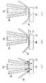
このような本実施形態の装置S1におけるレーザワイヤボンディング方法について、上記図1に加え、図2も参照して述べる。図2は、本実施形態のワイヤボンディング方法の要部を断面的に示す工程図である。
【0030】
まず、パッケージ30のターミナル31において1次ボンディングを行う。この1次ボンディングは、上記特許文献1に記載されている方法と同様にして行われる。
【0031】
すなわち、ワイヤ40を支持したワイヤガイド60およびノズル50をターミナル31の上に位置させ、ノズル50を下降させて、ワイヤ40をターミナル31に押しつける。これにより、ワイヤ40はターミナル31とノズル50との間に挟まれて固定される。この状態において、レーザビーム70をワイヤ40に照射することにより、ワイヤ40とターミナル31とが溶接される。
【0032】
こうして1次ボンディングを行った後、ワイヤ40を2次ボンディング側の被接合部材21上に位置させるとともにノズル50によってワイヤ40を該被接合部材21に押し付けた状態で、ワイヤ40にレーザを照射することにより、ワイヤ40を該被接合部材21に接合する工程を行う。
【0033】
すなわち、ワイヤガイド60からワイヤ40を引き出しながら、ノズル50およびワイヤガイド60を移動させ、2次ボンディング側の被接合部材つまり回路基板20のパッド21の上に位置させる。
【0034】
そして、ノズル50を下降させワイヤ40をパッド21に押しつける。これにより、ワイヤ40はパッド21とノズル50との間に挟まれて固定される。この状態において、レーザビーム70をワイヤ40に照射することにより、ワイヤ40とパッド21とが溶接される。
【0035】
このワイヤ40とパッド21とが溶接され2次ボンディングが行われた状態が図2(a)に示される。ここで、図2(a)では、ワイヤ40とパッド21とが溶け合った溶接部としての接合部80が示されている。
【0036】
この後、図2(b)、(c)に示すように、ワイヤ40のうち接合部80から離れた部位41にてワイヤ40を切断する工程を行う。
【0037】
このワイヤ40の切断工程では、ワイヤガイド60(図2では省略されている)によってワイヤ40の切断すべき部位41をパッド21から離すとともに、ノズル50を移動させてワイヤ40の切断すべき部位41の上に離して位置させた状態とする。そして、この状態でレーザビーム70の照射を再度行うことにより、ワイヤ40の切断を行う。
【0038】
それによれば、ワイヤ40の切断すべき部位41をパッド21およびノズル50から離した状態で、ワイヤ40の切断すべき部位41にレーザの照射を行うことになる。そのため、レーザ照射によってワイヤ40の切断すべき部位41に熱が集中し、低いエネルギーによってワイヤ40の切断を行うことができる。
【0039】
ちなみに、もし、ワイヤ40にノズル50やパッド21を接触させたままレーザを当てると、図2(a)中に矢印にて示すように放熱経路が生じる。つまり、ワイヤ40からノズル50やパッド21を介して熱の逃げが生じるので高エネルギーのレーザが必要になる。また、溶融したワイヤ40の一部が接触しているノズル50やパッド21に付着する可能性も高い。
【0040】
こうして、ワイヤボンディングが完了し、上記図1に示すように、パッケージ30のターミナル31と回路基板20のパッド21とがワイヤ40を介して結線され電気的に接続される。なお、以上のサイクルを、各ターミナル〜パッド間で繰り返すことにより、任意の本数、位置の電極間の結線が可能となる。
【0041】
このように、本実施形態のレーザワイヤボンディング方法によれば、カッターを用いないでワイヤ40の切断を行うことができる。その結果、カッターの交換が不要となり稼働率の向上が図れるとともに、ワイヤボンディング装置においてカッターおよびこれを駆動させる駆動部が無くなるため、被接合部材側の製品において部品配置の自由度が向上する。
【0042】
また、上記ワイヤ40の切断工程では、ワイヤ40に対してワイヤ40の長手方向に引っ張る力を加えながら、ワイヤ40の切断を行うことが好ましい。
【0043】
具体的には、図2(b)に示すように、ワイヤガイド60によってワイヤ40を矢印Kに示す方向へ引っ張るようにしながら、レーザビーム70の照射を行う。それによれば、ワイヤ40に対して当該引っ張る力を加えない状態で切断を行う場合に比べて、よりワイヤ40の切断が容易になるという利点がある。
【0044】
なお、上記実施形態では、装置S1において、パッケージ30のターミナル31を1次ボンディング側、回路基板20のパッド21を2次ボンディング側としたが、逆に、パッド21を1次ボンディング側、ターミナル31を2次ボンディング側としてもよい。この場合、ターミナル31へのワイヤ40の接合後にワイヤ40を切断する際に、上記レーザによる切断を行うようにする。
【0045】
また、本発明のワイヤボンディング方法は、上記装置S1以外にも適用できることは言うまでもない。例えば、半導体チップとリードフレームとの間のワイヤボンディングや、半導体チップ同士の間のワイヤボンディング、あるいは半導体チップと回路チップとの間のワイヤボンディング等に適用できることは明らかである。
【図面の簡単な説明】
【図1】本発明の実施形態に係るワイヤボンディング方法によりワイヤ接続が行われた後の装置の状態を示す概略断面図である。
【図2】上記実施形態のワイヤボンディング方法の要部を示す工程図である。
【符号の説明】
21…被接合部材としてのパッド、40…ワイヤ、
41…ワイヤの切断すべき部位、50…ノズル、80…ワイヤの接合部。[0001]
BACKGROUND OF THE INVENTION
The present invention relates to a laser wire bonding method for bonding a wire to a member to be bonded using a laser.
[0002]
[Prior art]
This type of wire bonding method is performed by a wire bonding apparatus including a nozzle capable of laser irradiation. That is, the wire is joined by irradiating the wire with a laser in a state where the wire is positioned on the member to be joined such as a pad or a terminal and the wire is pressed against the member to be joined by the nozzle (for example, (See
[0003]
After wire bonding, the wire is cut at a portion of the wire that is away from the bonded portion. This cutting is performed using a cutter that is provided integrally with a guide portion that guides the wire.
[0004]
[Patent Document 1]
Japanese Patent Laid-Open No. 7-37922
[Patent Document 2]
JP-A-5-343899 [0006]
[Problems to be solved by the invention]
However, as described above, conventionally, the cutting of the wire uses a cutter provided integrally with the guide member. Therefore, it is necessary to periodically replace the cutter due to wear of the cutter (blade). There was a problem that the operation rate decreased.
[0007]
In addition, it is necessary to prevent the cutter and the driving unit for driving the same from interfering with other parts in the product on the bonded member side, and accordingly, it is necessary to secure space. There was a restriction on the degree of freedom of component placement in the product.
[0008]
In view of the above problems, an object of the present invention is to enable cutting of a wire without using a cutter in a laser wire bonding method.
[0009]
[Means for Solving the Problems]
The present inventor has conducted intensive studies in consideration of irradiating the wire with a laser without using a cutter and cutting the wire with the heat.
[0010]
As a result, if a laser is applied with the nozzle or member to be joined in contact with the wire, heat escapes from the wire through the nozzle or member to be joined, so a high-energy laser is required. It has been found that if laser irradiation is performed in a state where other members such as the members to be joined are not brought into contact with each other, heat concentrates on the cut portion of the wire and can be cut with low energy. The present invention was created with the idea in mind.
[0011]
That is, in the first aspect of the invention, the wire (40) is positioned on the member to be joined (21) and the wire is irradiated with the laser while the wire is pressed against the member to be joined by the nozzle (50). In the wire bonding method including the step of bonding the wire to the member to be bonded, and then the step of cutting the wire at a site away from the bonding portion (80) of the wire, The wire is cut by moving the nozzle away from the member to be cut (41) and moving the nozzle away from the member to be cut, and irradiating the laser again. It is characterized by performing.
[0012]
According to this, in the cutting process of the wire (40), the portion to be cut of the wire is irradiated with the laser in a state where the portion to be cut (41) is separated from the member to be joined (21) and the nozzle (50). Will do. Therefore, heat concentrates on the part of the wire to be cut by laser irradiation, and the wire can be cut with low energy.
[0013]
Therefore, according to the present invention, the wire can be cut without using a cutter. As a result, it is not necessary to replace the cutter and the operating rate can be improved, and the cutter and the drive unit for driving the wire bonding apparatus are eliminated, so that the degree of freedom of component placement is improved in the product on the bonded member side.
[0014]
Here, as in the invention described in
[0015]
In addition, the code | symbol in the bracket | parenthesis of each said means is an example which shows a corresponding relationship with the specific means as described in embodiment mentioned later.
[0016]
DETAILED DESCRIPTION OF THE INVENTION
DESCRIPTION OF THE PREFERRED EMBODIMENTS Embodiments shown in the drawings will be described below. FIG. 1 is a schematic cross-sectional view showing a state of the device S1 after wire connection is performed by the wire bonding method of the present embodiment. The device S1 of this example is configured as a control circuit device mounted on an automobile or the like.
[0017]
In the device S1, a
[0018]
The
[0019]
Further, a
[0020]
The
[0021]
The
[0022]
1 shows the
[0023]
The
[0024]
In FIG. 1, a condensing lens is disposed above the
[0025]
The
[0026]
For example, the
[0027]
At the time of wire bonding, the apparatus S1 is mounted on a processing table (not shown), and this processing table is movable in a plane extending in a direction perpendicular to the paper surface in FIG. Specifically, this processing table is movable in the X and Y directions shown in FIG. 1, and is further rotatable about the Z direction.
[0028]
Thereby, the
[0029]
The laser wire bonding method in the apparatus S1 of this embodiment will be described with reference to FIG. 2 in addition to FIG. FIG. 2 is a process diagram showing in cross section the main part of the wire bonding method of this embodiment.
[0030]
First, primary bonding is performed at the terminal 31 of the
[0031]
That is, the
[0032]
After performing the primary bonding in this manner, the
[0033]
That is, while pulling out the
[0034]
Then, the
[0035]
FIG. 2A shows a state in which the
[0036]
Thereafter, as shown in FIGS. 2B and 2C, a step of cutting the
[0037]
In the cutting process of the
[0038]
According to this, the
[0039]
Incidentally, if a laser is applied while the
[0040]
Thus, the wire bonding is completed, and the
[0041]
Thus, according to the laser wire bonding method of this embodiment, the
[0042]
Further, in the step of cutting the
[0043]
Specifically, as shown in FIG. 2B, the
[0044]
In the above embodiment, in the device S1, the
[0045]
Needless to say, the wire bonding method of the present invention can be applied to devices other than the device S1. For example, it can be clearly applied to wire bonding between a semiconductor chip and a lead frame, wire bonding between semiconductor chips, or wire bonding between a semiconductor chip and a circuit chip.
[Brief description of the drawings]
FIG. 1 is a schematic cross-sectional view showing a state of an apparatus after wire connection is performed by a wire bonding method according to an embodiment of the present invention.
FIG. 2 is a process diagram showing the main part of the wire bonding method of the embodiment.
[Explanation of symbols]
21 ... Pad as a member to be joined, 40 ... Wire,
41... Part to be cut of the wire, 50... Nozzle, 80.
Claims (2)
Translated fromJapanese続いて、前記ワイヤのうち前記接合部(80)から離れた部位にて前記ワイヤを切断する工程とを備えるワイヤボンディング方法において、
前記ワイヤの切断工程では、前記ワイヤの切断すべき部位(41)を前記被接合部材から離すとともに、前記ノズルを移動させ前記ワイヤの切断すべき部位の上に離して位置させた状態で、レーザの照射を再度行うことにより、前記ワイヤの切断を行うことを特徴とするワイヤボンディング方法。The wire (40) is positioned on the member to be joined (21), and the wire is irradiated with a laser in a state where the wire (40) is pressed against the member to be joined by the nozzle (50). Joining the member;
Subsequently, in the wire bonding method including the step of cutting the wire at a site away from the joint (80) of the wire,
In the step of cutting the wire, the laser beam is moved in a state in which the portion (41) to be cut of the wire is separated from the member to be joined and the nozzle is moved to be separated from the portion to be cut of the wire. The wire bonding method is characterized in that the wire is cut by re-irradiating.
Priority Applications (1)
| Application Number | Priority Date | Filing Date | Title |
|---|---|---|---|
| JP2003067959AJP3885747B2 (en) | 2003-03-13 | 2003-03-13 | Wire bonding method |
Applications Claiming Priority (1)
| Application Number | Priority Date | Filing Date | Title |
|---|---|---|---|
| JP2003067959AJP3885747B2 (en) | 2003-03-13 | 2003-03-13 | Wire bonding method |
Publications (2)
| Publication Number | Publication Date |
|---|---|
| JP2004281514Atrue JP2004281514A (en) | 2004-10-07 |
| JP3885747B2 JP3885747B2 (en) | 2007-02-28 |
Family
ID=33285419
Family Applications (1)
| Application Number | Title | Priority Date | Filing Date |
|---|---|---|---|
| JP2003067959AExpired - Fee RelatedJP3885747B2 (en) | 2003-03-13 | 2003-03-13 | Wire bonding method |
Country Status (1)
| Country | Link |
|---|---|
| JP (1) | JP3885747B2 (en) |
Cited By (49)
| Publication number | Priority date | Publication date | Assignee | Title |
|---|---|---|---|---|
| WO2013126269A1 (en)* | 2012-02-24 | 2013-08-29 | Invensas Corporation | Method for package-on-package assembly with wire bonds to encapsulation surface |
| US8618659B2 (en) | 2011-05-03 | 2013-12-31 | Tessera, Inc. | Package-on-package assembly with wire bonds to encapsulation surface |
| US8623706B2 (en) | 2010-11-15 | 2014-01-07 | Tessera, Inc. | Microelectronic package with terminals on dielectric mass |
| US8728865B2 (en) | 2005-12-23 | 2014-05-20 | Tessera, Inc. | Microelectronic packages and methods therefor |
| US8835228B2 (en) | 2012-05-22 | 2014-09-16 | Invensas Corporation | Substrate-less stackable package with wire-bond interconnect |
| US8836136B2 (en) | 2011-10-17 | 2014-09-16 | Invensas Corporation | Package-on-package assembly with wire bond vias |
| US8878353B2 (en) | 2012-12-20 | 2014-11-04 | Invensas Corporation | Structure for microelectronic packaging with bond elements to encapsulation surface |
| US8883563B1 (en) | 2013-07-15 | 2014-11-11 | Invensas Corporation | Fabrication of microelectronic assemblies having stack terminals coupled by connectors extending through encapsulation |
| US8907466B2 (en) | 2010-07-19 | 2014-12-09 | Tessera, Inc. | Stackable molded microelectronic packages |
| US8927337B2 (en) | 2004-11-03 | 2015-01-06 | Tessera, Inc. | Stacked packaging improvements |
| US8975738B2 (en) | 2012-11-12 | 2015-03-10 | Invensas Corporation | Structure for microelectronic packaging with terminals on dielectric mass |
| US9023691B2 (en) | 2013-07-15 | 2015-05-05 | Invensas Corporation | Microelectronic assemblies with stack terminals coupled by connectors extending through encapsulation |
| US9034696B2 (en) | 2013-07-15 | 2015-05-19 | Invensas Corporation | Microelectronic assemblies having reinforcing collars on connectors extending through encapsulation |
| US9082753B2 (en) | 2013-11-12 | 2015-07-14 | Invensas Corporation | Severing bond wire by kinking and twisting |
| US9087815B2 (en) | 2013-11-12 | 2015-07-21 | Invensas Corporation | Off substrate kinking of bond wire |
| US9214454B2 (en) | 2014-03-31 | 2015-12-15 | Invensas Corporation | Batch process fabrication of package-on-package microelectronic assemblies |
| US9224717B2 (en) | 2011-05-03 | 2015-12-29 | Tessera, Inc. | Package-on-package assembly with wire bonds to encapsulation surface |
| US9324681B2 (en) | 2010-12-13 | 2016-04-26 | Tessera, Inc. | Pin attachment |
| US9349706B2 (en) | 2012-02-24 | 2016-05-24 | Invensas Corporation | Method for package-on-package assembly with wire bonds to encapsulation surface |
| US9391008B2 (en) | 2012-07-31 | 2016-07-12 | Invensas Corporation | Reconstituted wafer-level package DRAM |
| US9412714B2 (en) | 2014-05-30 | 2016-08-09 | Invensas Corporation | Wire bond support structure and microelectronic package including wire bonds therefrom |
| US9502390B2 (en) | 2012-08-03 | 2016-11-22 | Invensas Corporation | BVA interposer |
| US9530749B2 (en) | 2015-04-28 | 2016-12-27 | Invensas Corporation | Coupling of side surface contacts to a circuit platform |
| US9553076B2 (en) | 2010-07-19 | 2017-01-24 | Tessera, Inc. | Stackable molded microelectronic packages with area array unit connectors |
| US9583411B2 (en) | 2014-01-17 | 2017-02-28 | Invensas Corporation | Fine pitch BVA using reconstituted wafer with area array accessible for testing |
| US9601454B2 (en) | 2013-02-01 | 2017-03-21 | Invensas Corporation | Method of forming a component having wire bonds and a stiffening layer |
| US9646917B2 (en) | 2014-05-29 | 2017-05-09 | Invensas Corporation | Low CTE component with wire bond interconnects |
| US9659848B1 (en) | 2015-11-18 | 2017-05-23 | Invensas Corporation | Stiffened wires for offset BVA |
| US9685365B2 (en) | 2013-08-08 | 2017-06-20 | Invensas Corporation | Method of forming a wire bond having a free end |
| US9728527B2 (en) | 2013-11-22 | 2017-08-08 | Invensas Corporation | Multiple bond via arrays of different wire heights on a same substrate |
| US9735084B2 (en) | 2014-12-11 | 2017-08-15 | Invensas Corporation | Bond via array for thermal conductivity |
| US9761554B2 (en) | 2015-05-07 | 2017-09-12 | Invensas Corporation | Ball bonding metal wire bond wires to metal pads |
| US9812402B2 (en) | 2015-10-12 | 2017-11-07 | Invensas Corporation | Wire bond wires for interference shielding |
| US9842745B2 (en) | 2012-02-17 | 2017-12-12 | Invensas Corporation | Heat spreading substrate with embedded interconnects |
| US9852969B2 (en) | 2013-11-22 | 2017-12-26 | Invensas Corporation | Die stacks with one or more bond via arrays of wire bond wires and with one or more arrays of bump interconnects |
| US9888579B2 (en) | 2015-03-05 | 2018-02-06 | Invensas Corporation | Pressing of wire bond wire tips to provide bent-over tips |
| US9911718B2 (en) | 2015-11-17 | 2018-03-06 | Invensas Corporation | ‘RDL-First’ packaged microelectronic device for a package-on-package device |
| US9935075B2 (en) | 2016-07-29 | 2018-04-03 | Invensas Corporation | Wire bonding method and apparatus for electromagnetic interference shielding |
| US9984992B2 (en) | 2015-12-30 | 2018-05-29 | Invensas Corporation | Embedded wire bond wires for vertical integration with separate surface mount and wire bond mounting surfaces |
| US10008477B2 (en) | 2013-09-16 | 2018-06-26 | Invensas Corporation | Microelectronic element with bond elements to encapsulation surface |
| US10008469B2 (en) | 2015-04-30 | 2018-06-26 | Invensas Corporation | Wafer-level packaging using wire bond wires in place of a redistribution layer |
| US10026717B2 (en) | 2013-11-22 | 2018-07-17 | Invensas Corporation | Multiple bond via arrays of different wire heights on a same substrate |
| US10181457B2 (en) | 2015-10-26 | 2019-01-15 | Invensas Corporation | Microelectronic package for wafer-level chip scale packaging with fan-out |
| US10299368B2 (en) | 2016-12-21 | 2019-05-21 | Invensas Corporation | Surface integrated waveguides and circuit structures therefor |
| US10332854B2 (en) | 2015-10-23 | 2019-06-25 | Invensas Corporation | Anchoring structure of fine pitch bva |
| US10381326B2 (en) | 2014-05-28 | 2019-08-13 | Invensas Corporation | Structure and method for integrated circuits packaging with increased density |
| US10460958B2 (en) | 2013-08-07 | 2019-10-29 | Invensas Corporation | Method of manufacturing embedded packaging with preformed vias |
| US10490528B2 (en) | 2015-10-12 | 2019-11-26 | Invensas Corporation | Embedded wire bond wires |
| CN116313940A (en)* | 2023-05-18 | 2023-06-23 | 上海聚跃检测技术有限公司 | Cutting method and auxiliary cutting device for wire bonding structure |
- 2003
- 2003-03-13JPJP2003067959Apatent/JP3885747B2/ennot_activeExpired - Fee Related
Cited By (102)
| Publication number | Priority date | Publication date | Assignee | Title |
|---|---|---|---|---|
| US9570416B2 (en) | 2004-11-03 | 2017-02-14 | Tessera, Inc. | Stacked packaging improvements |
| US9153562B2 (en) | 2004-11-03 | 2015-10-06 | Tessera, Inc. | Stacked packaging improvements |
| US8927337B2 (en) | 2004-11-03 | 2015-01-06 | Tessera, Inc. | Stacked packaging improvements |
| US9984901B2 (en) | 2005-12-23 | 2018-05-29 | Tessera, Inc. | Method for making a microelectronic assembly having conductive elements |
| US8728865B2 (en) | 2005-12-23 | 2014-05-20 | Tessera, Inc. | Microelectronic packages and methods therefor |
| US9218988B2 (en) | 2005-12-23 | 2015-12-22 | Tessera, Inc. | Microelectronic packages and methods therefor |
| US8907466B2 (en) | 2010-07-19 | 2014-12-09 | Tessera, Inc. | Stackable molded microelectronic packages |
| US10128216B2 (en) | 2010-07-19 | 2018-11-13 | Tessera, Inc. | Stackable molded microelectronic packages |
| US9570382B2 (en) | 2010-07-19 | 2017-02-14 | Tessera, Inc. | Stackable molded microelectronic packages |
| US9553076B2 (en) | 2010-07-19 | 2017-01-24 | Tessera, Inc. | Stackable molded microelectronic packages with area array unit connectors |
| US9123664B2 (en) | 2010-07-19 | 2015-09-01 | Tessera, Inc. | Stackable molded microelectronic packages |
| US8623706B2 (en) | 2010-11-15 | 2014-01-07 | Tessera, Inc. | Microelectronic package with terminals on dielectric mass |
| US8659164B2 (en) | 2010-11-15 | 2014-02-25 | Tessera, Inc. | Microelectronic package with terminals on dielectric mass |
| US8957527B2 (en) | 2010-11-15 | 2015-02-17 | Tessera, Inc. | Microelectronic package with terminals on dielectric mass |
| US8637991B2 (en) | 2010-11-15 | 2014-01-28 | Tessera, Inc. | Microelectronic package with terminals on dielectric mass |
| US9324681B2 (en) | 2010-12-13 | 2016-04-26 | Tessera, Inc. | Pin attachment |
| US11424211B2 (en) | 2011-05-03 | 2022-08-23 | Tessera Llc | Package-on-package assembly with wire bonds to encapsulation surface |
| US10062661B2 (en) | 2011-05-03 | 2018-08-28 | Tessera, Inc. | Package-on-package assembly with wire bonds to encapsulation surface |
| US9224717B2 (en) | 2011-05-03 | 2015-12-29 | Tessera, Inc. | Package-on-package assembly with wire bonds to encapsulation surface |
| US10593643B2 (en) | 2011-05-03 | 2020-03-17 | Tessera, Inc. | Package-on-package assembly with wire bonds to encapsulation surface |
| US9093435B2 (en) | 2011-05-03 | 2015-07-28 | Tessera, Inc. | Package-on-package assembly with wire bonds to encapsulation surface |
| US8618659B2 (en) | 2011-05-03 | 2013-12-31 | Tessera, Inc. | Package-on-package assembly with wire bonds to encapsulation surface |
| US9691731B2 (en) | 2011-05-03 | 2017-06-27 | Tessera, Inc. | Package-on-package assembly with wire bonds to encapsulation surface |
| US9105483B2 (en) | 2011-10-17 | 2015-08-11 | Invensas Corporation | Package-on-package assembly with wire bond vias |
| US11189595B2 (en) | 2011-10-17 | 2021-11-30 | Invensas Corporation | Package-on-package assembly with wire bond vias |
| US11735563B2 (en) | 2011-10-17 | 2023-08-22 | Invensas Llc | Package-on-package assembly with wire bond vias |
| US9761558B2 (en) | 2011-10-17 | 2017-09-12 | Invensas Corporation | Package-on-package assembly with wire bond vias |
| US9041227B2 (en) | 2011-10-17 | 2015-05-26 | Invensas Corporation | Package-on-package assembly with wire bond vias |
| US9252122B2 (en) | 2011-10-17 | 2016-02-02 | Invensas Corporation | Package-on-package assembly with wire bond vias |
| US8836136B2 (en) | 2011-10-17 | 2014-09-16 | Invensas Corporation | Package-on-package assembly with wire bond vias |
| US10756049B2 (en) | 2011-10-17 | 2020-08-25 | Invensas Corporation | Package-on-package assembly with wire bond vias |
| US9842745B2 (en) | 2012-02-17 | 2017-12-12 | Invensas Corporation | Heat spreading substrate with embedded interconnects |
| US8772152B2 (en) | 2012-02-24 | 2014-07-08 | Invensas Corporation | Method for package-on-package assembly with wire bonds to encapsulation surface |
| US9349706B2 (en) | 2012-02-24 | 2016-05-24 | Invensas Corporation | Method for package-on-package assembly with wire bonds to encapsulation surface |
| WO2013126269A1 (en)* | 2012-02-24 | 2013-08-29 | Invensas Corporation | Method for package-on-package assembly with wire bonds to encapsulation surface |
| US9691679B2 (en) | 2012-02-24 | 2017-06-27 | Invensas Corporation | Method for package-on-package assembly with wire bonds to encapsulation surface |
| US9953914B2 (en) | 2012-05-22 | 2018-04-24 | Invensas Corporation | Substrate-less stackable package with wire-bond interconnect |
| US8835228B2 (en) | 2012-05-22 | 2014-09-16 | Invensas Corporation | Substrate-less stackable package with wire-bond interconnect |
| US10170412B2 (en) | 2012-05-22 | 2019-01-01 | Invensas Corporation | Substrate-less stackable package with wire-bond interconnect |
| US10510659B2 (en) | 2012-05-22 | 2019-12-17 | Invensas Corporation | Substrate-less stackable package with wire-bond interconnect |
| US9391008B2 (en) | 2012-07-31 | 2016-07-12 | Invensas Corporation | Reconstituted wafer-level package DRAM |
| US9917073B2 (en) | 2012-07-31 | 2018-03-13 | Invensas Corporation | Reconstituted wafer-level package dram with conductive interconnects formed in encapsulant at periphery of the package |
| US9502390B2 (en) | 2012-08-03 | 2016-11-22 | Invensas Corporation | BVA interposer |
| US10297582B2 (en) | 2012-08-03 | 2019-05-21 | Invensas Corporation | BVA interposer |
| US8975738B2 (en) | 2012-11-12 | 2015-03-10 | Invensas Corporation | Structure for microelectronic packaging with terminals on dielectric mass |
| US9615456B2 (en) | 2012-12-20 | 2017-04-04 | Invensas Corporation | Microelectronic assembly for microelectronic packaging with bond elements to encapsulation surface |
| US9095074B2 (en) | 2012-12-20 | 2015-07-28 | Invensas Corporation | Structure for microelectronic packaging with bond elements to encapsulation surface |
| US8878353B2 (en) | 2012-12-20 | 2014-11-04 | Invensas Corporation | Structure for microelectronic packaging with bond elements to encapsulation surface |
| US9601454B2 (en) | 2013-02-01 | 2017-03-21 | Invensas Corporation | Method of forming a component having wire bonds and a stiffening layer |
| US9023691B2 (en) | 2013-07-15 | 2015-05-05 | Invensas Corporation | Microelectronic assemblies with stack terminals coupled by connectors extending through encapsulation |
| US9633979B2 (en) | 2013-07-15 | 2017-04-25 | Invensas Corporation | Microelectronic assemblies having stack terminals coupled by connectors extending through encapsulation |
| US8883563B1 (en) | 2013-07-15 | 2014-11-11 | Invensas Corporation | Fabrication of microelectronic assemblies having stack terminals coupled by connectors extending through encapsulation |
| US9034696B2 (en) | 2013-07-15 | 2015-05-19 | Invensas Corporation | Microelectronic assemblies having reinforcing collars on connectors extending through encapsulation |
| US10460958B2 (en) | 2013-08-07 | 2019-10-29 | Invensas Corporation | Method of manufacturing embedded packaging with preformed vias |
| US9685365B2 (en) | 2013-08-08 | 2017-06-20 | Invensas Corporation | Method of forming a wire bond having a free end |
| US10008477B2 (en) | 2013-09-16 | 2018-06-26 | Invensas Corporation | Microelectronic element with bond elements to encapsulation surface |
| US9082753B2 (en) | 2013-11-12 | 2015-07-14 | Invensas Corporation | Severing bond wire by kinking and twisting |
| US9087815B2 (en) | 2013-11-12 | 2015-07-21 | Invensas Corporation | Off substrate kinking of bond wire |
| US9893033B2 (en) | 2013-11-12 | 2018-02-13 | Invensas Corporation | Off substrate kinking of bond wire |
| US10290613B2 (en) | 2013-11-22 | 2019-05-14 | Invensas Corporation | Multiple bond via arrays of different wire heights on a same substrate |
| US9852969B2 (en) | 2013-11-22 | 2017-12-26 | Invensas Corporation | Die stacks with one or more bond via arrays of wire bond wires and with one or more arrays of bump interconnects |
| USRE49987E1 (en) | 2013-11-22 | 2024-05-28 | Invensas Llc | Multiple plated via arrays of different wire heights on a same substrate |
| US9728527B2 (en) | 2013-11-22 | 2017-08-08 | Invensas Corporation | Multiple bond via arrays of different wire heights on a same substrate |
| US10026717B2 (en) | 2013-11-22 | 2018-07-17 | Invensas Corporation | Multiple bond via arrays of different wire heights on a same substrate |
| US10629567B2 (en) | 2013-11-22 | 2020-04-21 | Invensas Corporation | Multiple plated via arrays of different wire heights on same substrate |
| US11990382B2 (en) | 2014-01-17 | 2024-05-21 | Adeia Semiconductor Technologies Llc | Fine pitch BVA using reconstituted wafer with area array accessible for testing |
| US11404338B2 (en) | 2014-01-17 | 2022-08-02 | Invensas Corporation | Fine pitch bva using reconstituted wafer with area array accessible for testing |
| US9837330B2 (en) | 2014-01-17 | 2017-12-05 | Invensas Corporation | Fine pitch BVA using reconstituted wafer with area array accessible for testing |
| US9583411B2 (en) | 2014-01-17 | 2017-02-28 | Invensas Corporation | Fine pitch BVA using reconstituted wafer with area array accessible for testing |
| US10529636B2 (en) | 2014-01-17 | 2020-01-07 | Invensas Corporation | Fine pitch BVA using reconstituted wafer with area array accessible for testing |
| US9356006B2 (en) | 2014-03-31 | 2016-05-31 | Invensas Corporation | Batch process fabrication of package-on-package microelectronic assemblies |
| US9214454B2 (en) | 2014-03-31 | 2015-12-15 | Invensas Corporation | Batch process fabrication of package-on-package microelectronic assemblies |
| US9812433B2 (en) | 2014-03-31 | 2017-11-07 | Invensas Corporation | Batch process fabrication of package-on-package microelectronic assemblies |
| US10381326B2 (en) | 2014-05-28 | 2019-08-13 | Invensas Corporation | Structure and method for integrated circuits packaging with increased density |
| US10032647B2 (en) | 2014-05-29 | 2018-07-24 | Invensas Corporation | Low CTE component with wire bond interconnects |
| US10475726B2 (en) | 2014-05-29 | 2019-11-12 | Invensas Corporation | Low CTE component with wire bond interconnects |
| US9646917B2 (en) | 2014-05-29 | 2017-05-09 | Invensas Corporation | Low CTE component with wire bond interconnects |
| US9412714B2 (en) | 2014-05-30 | 2016-08-09 | Invensas Corporation | Wire bond support structure and microelectronic package including wire bonds therefrom |
| US9947641B2 (en) | 2014-05-30 | 2018-04-17 | Invensas Corporation | Wire bond support structure and microelectronic package including wire bonds therefrom |
| US9735084B2 (en) | 2014-12-11 | 2017-08-15 | Invensas Corporation | Bond via array for thermal conductivity |
| US10806036B2 (en) | 2015-03-05 | 2020-10-13 | Invensas Corporation | Pressing of wire bond wire tips to provide bent-over tips |
| US9888579B2 (en) | 2015-03-05 | 2018-02-06 | Invensas Corporation | Pressing of wire bond wire tips to provide bent-over tips |
| US9530749B2 (en) | 2015-04-28 | 2016-12-27 | Invensas Corporation | Coupling of side surface contacts to a circuit platform |
| US10008469B2 (en) | 2015-04-30 | 2018-06-26 | Invensas Corporation | Wafer-level packaging using wire bond wires in place of a redistribution layer |
| US9761554B2 (en) | 2015-05-07 | 2017-09-12 | Invensas Corporation | Ball bonding metal wire bond wires to metal pads |
| US11462483B2 (en) | 2015-10-12 | 2022-10-04 | Invensas Llc | Wire bond wires for interference shielding |
| US10490528B2 (en) | 2015-10-12 | 2019-11-26 | Invensas Corporation | Embedded wire bond wires |
| US10115678B2 (en) | 2015-10-12 | 2018-10-30 | Invensas Corporation | Wire bond wires for interference shielding |
| US10559537B2 (en) | 2015-10-12 | 2020-02-11 | Invensas Corporation | Wire bond wires for interference shielding |
| US9812402B2 (en) | 2015-10-12 | 2017-11-07 | Invensas Corporation | Wire bond wires for interference shielding |
| US10332854B2 (en) | 2015-10-23 | 2019-06-25 | Invensas Corporation | Anchoring structure of fine pitch bva |
| US10181457B2 (en) | 2015-10-26 | 2019-01-15 | Invensas Corporation | Microelectronic package for wafer-level chip scale packaging with fan-out |
| US10043779B2 (en) | 2015-11-17 | 2018-08-07 | Invensas Corporation | Packaged microelectronic device for a package-on-package device |
| US9911718B2 (en) | 2015-11-17 | 2018-03-06 | Invensas Corporation | ‘RDL-First’ packaged microelectronic device for a package-on-package device |
| US9659848B1 (en) | 2015-11-18 | 2017-05-23 | Invensas Corporation | Stiffened wires for offset BVA |
| US10325877B2 (en) | 2015-12-30 | 2019-06-18 | Invensas Corporation | Embedded wire bond wires for vertical integration with separate surface mount and wire bond mounting surfaces |
| US9984992B2 (en) | 2015-12-30 | 2018-05-29 | Invensas Corporation | Embedded wire bond wires for vertical integration with separate surface mount and wire bond mounting surfaces |
| US10658302B2 (en) | 2016-07-29 | 2020-05-19 | Invensas Corporation | Wire bonding method and apparatus for electromagnetic interference shielding |
| US9935075B2 (en) | 2016-07-29 | 2018-04-03 | Invensas Corporation | Wire bonding method and apparatus for electromagnetic interference shielding |
| US10299368B2 (en) | 2016-12-21 | 2019-05-21 | Invensas Corporation | Surface integrated waveguides and circuit structures therefor |
| CN116313940A (en)* | 2023-05-18 | 2023-06-23 | 上海聚跃检测技术有限公司 | Cutting method and auxiliary cutting device for wire bonding structure |
| CN116313940B (en)* | 2023-05-18 | 2023-08-11 | 上海聚跃检测技术有限公司 | Cutting method and auxiliary cutting device for wire bonding structure |
Also Published As
| Publication number | Publication date |
|---|---|
| JP3885747B2 (en) | 2007-02-28 |
Similar Documents
| Publication | Publication Date | Title |
|---|---|---|
| JP3885747B2 (en) | Wire bonding method | |
| US5872405A (en) | Laser wire bonding for wire embedded dielectrics to integrated circuits | |
| US6892927B2 (en) | Method and apparatus for bonding a wire to a bond pad on a device | |
| JPH10135220A (en) | Bump-forming method | |
| US4587395A (en) | Bonding leads to semiconductor devices | |
| CN101271834A (en) | Device Manufacturing Method | |
| JP5651575B2 (en) | Wire bonding apparatus and wire bonding method | |
| JP2009146979A (en) | Photoelectric conversion device | |
| WO1998031498A1 (en) | Laser-driven microwelding apparatus and process | |
| JP3739091B2 (en) | Manufacturing method of semiconductor device | |
| JP2006289388A (en) | Laser processing equipment | |
| JP3922870B2 (en) | Implementation method | |
| JP2012190950A (en) | Conductive pattern member for substrate for power module | |
| JPH1022328A (en) | Bonding method and apparatus | |
| JP5489808B2 (en) | Manufacturing method of semiconductor device | |
| JP5070868B2 (en) | Mounting method of semiconductor chip | |
| JPH05109808A (en) | Wire bonding method and device thereof | |
| CN113380684A (en) | Manufacturing method, manufacturing apparatus, jig assembly, semiconductor module, and vehicle | |
| JP3676995B2 (en) | Bump bonding method and apparatus | |
| JP4522752B2 (en) | Terminal joining method by soldering | |
| JPH0951162A (en) | Electronic-component mounting apparatus | |
| JPH0737890A (en) | Solder ball joining apparatus and joining method thereof | |
| JPH0682701B2 (en) | Wire bonding method and apparatus | |
| JPH07273267A (en) | Lead joining method | |
| JP2004273507A (en) | Wire bonding device |
Legal Events
| Date | Code | Title | Description |
|---|---|---|---|
| A621 | Written request for application examination | Free format text:JAPANESE INTERMEDIATE CODE: A621 Effective date:20050509 | |
| A977 | Report on retrieval | Free format text:JAPANESE INTERMEDIATE CODE: A971007 Effective date:20061026 | |
| TRDD | Decision of grant or rejection written | ||
| A01 | Written decision to grant a patent or to grant a registration (utility model) | Free format text:JAPANESE INTERMEDIATE CODE: A01 Effective date:20061031 | |
| A61 | First payment of annual fees (during grant procedure) | Free format text:JAPANESE INTERMEDIATE CODE: A61 Effective date:20061113 | |
| R150 | Certificate of patent or registration of utility model | Free format text:JAPANESE INTERMEDIATE CODE: R150 | |
| FPAY | Renewal fee payment (event date is renewal date of database) | Free format text:PAYMENT UNTIL: 20091201 Year of fee payment:3 | |
| FPAY | Renewal fee payment (event date is renewal date of database) | Free format text:PAYMENT UNTIL: 20101201 Year of fee payment:4 | |
| FPAY | Renewal fee payment (event date is renewal date of database) | Free format text:PAYMENT UNTIL: 20111201 Year of fee payment:5 | |
| FPAY | Renewal fee payment (event date is renewal date of database) | Free format text:PAYMENT UNTIL: 20121201 Year of fee payment:6 | |
| LAPS | Cancellation because of no payment of annual fees |