JP2004278738A - Bearing unit - Google Patents
Bearing unitDownload PDFInfo
- Publication number
- JP2004278738A JP2004278738AJP2003073461AJP2003073461AJP2004278738AJP 2004278738 AJP2004278738 AJP 2004278738AJP 2003073461 AJP2003073461 AJP 2003073461AJP 2003073461 AJP2003073461 AJP 2003073461AJP 2004278738 AJP2004278738 AJP 2004278738A
- Authority
- JP
- Japan
- Prior art keywords
- bearing unit
- inner ring
- fitting base
- peripheral groove
- oil seal
- Prior art date
- Legal status (The legal status is an assumption and is not a legal conclusion. Google has not performed a legal analysis and makes no representation as to the accuracy of the status listed.)
- Granted
Links
- 230000002093peripheral effectEffects0.000claimsabstractdescription42
- 238000007789sealingMethods0.000claimsabstractdescription17
- 238000005096rolling processMethods0.000claimsabstractdescription6
- XLYOFNOQVPJJNP-UHFFFAOYSA-NwaterSubstancesOXLYOFNOQVPJJNP-UHFFFAOYSA-N0.000description8
- 239000000314lubricantSubstances0.000description7
- 230000000694effectsEffects0.000description5
- 238000009749continuous castingMethods0.000description3
- 239000013013elastic materialSubstances0.000description2
- 238000009434installationMethods0.000description2
- 239000002184metalSubstances0.000description2
- 230000006835compressionEffects0.000description1
- 238000007906compressionMethods0.000description1
- 230000007423decreaseEffects0.000description1
- 239000000428dustSubstances0.000description1
- 210000004907glandAnatomy0.000description1
- 230000008595infiltrationEffects0.000description1
- 238000001764infiltrationMethods0.000description1
- 238000012856packingMethods0.000description1
Images


Classifications
- F—MECHANICAL ENGINEERING; LIGHTING; HEATING; WEAPONS; BLASTING
- F16—ENGINEERING ELEMENTS AND UNITS; GENERAL MEASURES FOR PRODUCING AND MAINTAINING EFFECTIVE FUNCTIONING OF MACHINES OR INSTALLATIONS; THERMAL INSULATION IN GENERAL
- F16C—SHAFTS; FLEXIBLE SHAFTS; ELEMENTS OR CRANKSHAFT MECHANISMS; ROTARY BODIES OTHER THAN GEARING ELEMENTS; BEARINGS
- F16C33/00—Parts of bearings; Special methods for making bearings or parts thereof
- F16C33/72—Sealings
- F16C33/76—Sealings of ball or roller bearings
- F16C33/78—Sealings of ball or roller bearings with a diaphragm, disc, or ring, with or without resilient members
- F16C33/7816—Details of the sealing or parts thereof, e.g. geometry, material
- F16C33/783—Details of the sealing or parts thereof, e.g. geometry, material of the mounting region
- F—MECHANICAL ENGINEERING; LIGHTING; HEATING; WEAPONS; BLASTING
- F16—ENGINEERING ELEMENTS AND UNITS; GENERAL MEASURES FOR PRODUCING AND MAINTAINING EFFECTIVE FUNCTIONING OF MACHINES OR INSTALLATIONS; THERMAL INSULATION IN GENERAL
- F16C—SHAFTS; FLEXIBLE SHAFTS; ELEMENTS OR CRANKSHAFT MECHANISMS; ROTARY BODIES OTHER THAN GEARING ELEMENTS; BEARINGS
- F16C33/00—Parts of bearings; Special methods for making bearings or parts thereof
- F16C33/30—Parts of ball or roller bearings
- F16C33/58—Raceways; Race rings
- F16C33/583—Details of specific parts of races
- F—MECHANICAL ENGINEERING; LIGHTING; HEATING; WEAPONS; BLASTING
- F16—ENGINEERING ELEMENTS AND UNITS; GENERAL MEASURES FOR PRODUCING AND MAINTAINING EFFECTIVE FUNCTIONING OF MACHINES OR INSTALLATIONS; THERMAL INSULATION IN GENERAL
- F16C—SHAFTS; FLEXIBLE SHAFTS; ELEMENTS OR CRANKSHAFT MECHANISMS; ROTARY BODIES OTHER THAN GEARING ELEMENTS; BEARINGS
- F16C33/00—Parts of bearings; Special methods for making bearings or parts thereof
- F16C33/72—Sealings
- F16C33/76—Sealings of ball or roller bearings
- F16C33/78—Sealings of ball or roller bearings with a diaphragm, disc, or ring, with or without resilient members
- F16C33/7889—Sealings of ball or roller bearings with a diaphragm, disc, or ring, with or without resilient members mounted to an inner race and extending toward the outer race
- F—MECHANICAL ENGINEERING; LIGHTING; HEATING; WEAPONS; BLASTING
- F16—ENGINEERING ELEMENTS AND UNITS; GENERAL MEASURES FOR PRODUCING AND MAINTAINING EFFECTIVE FUNCTIONING OF MACHINES OR INSTALLATIONS; THERMAL INSULATION IN GENERAL
- F16C—SHAFTS; FLEXIBLE SHAFTS; ELEMENTS OR CRANKSHAFT MECHANISMS; ROTARY BODIES OTHER THAN GEARING ELEMENTS; BEARINGS
- F16C19/00—Bearings with rolling contact, for exclusively rotary movement
- F16C19/22—Bearings with rolling contact, for exclusively rotary movement with bearing rollers essentially of the same size in one or more circular rows, e.g. needle bearings
- F16C19/24—Bearings with rolling contact, for exclusively rotary movement with bearing rollers essentially of the same size in one or more circular rows, e.g. needle bearings for radial load mainly
- F16C19/26—Bearings with rolling contact, for exclusively rotary movement with bearing rollers essentially of the same size in one or more circular rows, e.g. needle bearings for radial load mainly with a single row of rollers
- F—MECHANICAL ENGINEERING; LIGHTING; HEATING; WEAPONS; BLASTING
- F16—ENGINEERING ELEMENTS AND UNITS; GENERAL MEASURES FOR PRODUCING AND MAINTAINING EFFECTIVE FUNCTIONING OF MACHINES OR INSTALLATIONS; THERMAL INSULATION IN GENERAL
- F16C—SHAFTS; FLEXIBLE SHAFTS; ELEMENTS OR CRANKSHAFT MECHANISMS; ROTARY BODIES OTHER THAN GEARING ELEMENTS; BEARINGS
- F16C23/00—Bearings for exclusively rotary movement adjustable for aligning or positioning
- F16C23/06—Ball or roller bearings
- F16C23/08—Ball or roller bearings self-adjusting
- F16C23/082—Ball or roller bearings self-adjusting by means of at least one substantially spherical surface
- F16C23/084—Ball or roller bearings self-adjusting by means of at least one substantially spherical surface sliding on a complementary spherical surface
Landscapes
- Engineering & Computer Science (AREA)
- General Engineering & Computer Science (AREA)
- Mechanical Engineering (AREA)
- Sealing Of Bearings (AREA)
- Rolling Contact Bearings (AREA)
Abstract
Description
Translated fromJapanese【0001】
【発明の属する技術分野】
本発明は、軸受ユニットに関する。
【0002】
【従来の技術】
連続鋳造設備で使用されるピンチロールは、負荷される荷重が大きいため、両端で支持されるほか、中央部でも支持されることがある。この場合、ピンチロールの中央部の支持には、組み立て上の制約から、2つ割り型の軸受ユニットが使用される(特許文献1参照)。
【0003】
従来の2つ割り型軸受ユニットは、2つ割りの外輪と、同じく2つ割りの内輪と、これら内外輪の間に配置される複数の転動体と、前記2つ割りの内輪を環状に結合する締結リングとを含むもので、上下2つ割りのハウジング内に設けられる。この軸受ユニットでは、潤滑剤の保持と、防水や防塵のために、内輪軌道面の軸方向外側で、内輪もしくはこの内輪と一体の部材(特許文献1の例では締結リング)の外周部に周溝が形成されていて、この周溝にオイルシール等のシール部材が嵌め込みにより取り付けられている。なお、シール部材は、少なくとも周方向1個所に割れ目を有し、この割れ目を中心に大径に拡開できるようになっている。
【0004】
【特許文献1】
実公平6−4098号公報
【0005】
【発明が解決しようとする課題】
ところで、上記のような軸受ユニットでは、オイルシールの取り付け状態を強固にするために、オイルシールの嵌め込み基部を圧縮した状態で、周溝の内部に嵌め込む必要がある。しかし、その嵌め込みの際、オイルシールの嵌め込み基部の側面が、周溝の内壁面と全面的に圧接することになるので、嵌め込みに対する抵抗が大きく、オイルシールの取り付け作業が容易ではなく、それだけ軸受ユニット全体の組み立てに時間がかかる。オイルシールの取り付け状態が不確実であると、オイルシール自体が使用中に脱落したり、またオイルシールのリップが必要以上に外径側に突出して、その突出部分が早期に摩耗する等の不具合が生じる。
【0006】
これに対して、オイルシールの嵌め込み基部の幅を狭くする等して、オイルシールの周溝への嵌め込みを容易にすると、組み立ての作業性は向上するが、オイルシールの嵌め込み基部と周溝との密着度が減少し、外部から水や異物が浸入しやすくなり、シール性能が低下する。
【0007】
本発明は、上記の問題に対処したもので、シール性能を低下させることなく、内輪側の周溝へのシール部材の取り付けが容易、確実にできるようにすることを課題とする。
【0008】
【課題を解決するための手段】
上記課題を達成するために、本件発明者が種々検討したところ、軸受ユニットでは、オイルシールの嵌め込み基部の側面に、凸部を全周にわたって形成する試みがなされている。この構成では、オイルシールを周溝に嵌め込む際の抵抗が小さくなると考えられている。
【0009】
しかし、単にオイルシールの嵌め込み基部に凸部を設けただけの構成では、凸部を含む嵌め込み基部は、周溝の限られた空間内で圧縮されることになるので、変形する余裕が少なく、嵌め込みに対する抵抗は余り小さくならない。この欠点は、大型のものほど顕著で、大径のオイルシールの取り付けにはかなりの手間がかかる。これに対して、凸部の突出量を小さくするか、周溝の幅を広くする等して、オイルシールの嵌め込みを容易にすると、シール性能が低下する。
【0010】
本発明は、上記のような事情を考慮してなされたものであって、外輪と、この外輪に転動体を介して回転可能に支持される内輪と、内輪の軌道面の軸方向外側で内輪もしくはこの内輪と一体の部材の外周部に形成されて軸方向とほぼ直交する内壁面を有する周溝と、この周溝に嵌め込みにより取り付けられ前記外輪側の部材の内周面に摺接する弾性摺接部を有するシール部材とを備え、前記シール部材には、その嵌め込み基部の側面に、前記周溝の内壁面に圧接する凸部がシール部材の全周にわたって形成されるとともに、前記凸部の外径側に、圧縮変形した前記凸部を受け入れる受け入れ凹部が形成されている軸受ユニットを構成した。
【0011】
上記構成における「周溝」とは、コ字形断面の角溝だけでなく、断面がU字形の溝も含み、開口部の両側に、この軸受ユニットの軸方向とほぼ直交する内壁面を有する溝を意味する。
【0012】
上記構成において、この軸受ユニットの組み立てに当たっては、内輪側にある周溝に、シール部材の嵌め込み基部を嵌め込む。この場合、嵌め込み基部の側面からは凸部が突出しているから、嵌め込み基部の側面の各部分のうち、凸部が周溝の内壁面に大きな接触圧で接触し、凸部に周溝内壁面との接触圧が集中する。そのため、嵌め込み基部の嵌め込みに対する抵抗が小さく、容易に嵌め込みができる。
【0013】
しかも、嵌め込み基部の周溝内への嵌め込みに伴い、凸部は、圧縮されるとともに、外径側に折り畳まれるように変形して、その外径側にある受け入れ凹部内に入り込む。このように、嵌め込み基部では、凸部の圧縮された分が受け入れ凹部内に逃げることになり、周溝の限られた空間内でも、凸部を含む嵌め込み基部の全体は柔軟に変形する。そのため、嵌め込み基部は、抵抗少なく容易に周溝の奥の所定深さまで嵌め込むことができる。
【0014】
さらに、シール部材の嵌め込み基部を周溝の内部に嵌め込んだ状態では、凸部が受け入れ凹部内に入り込むことで、嵌め込み基部の側面が平坦化し、この平坦化した側面の全面がほぼ均等の接触圧で周溝の内壁面に圧接するので、周溝の内壁面との密着度が増し、高いシール性能を発揮する。
【0015】
前記の凸部とその外径側の受け入れ凹部とは、シール部材の嵌め込み基部の一方の側面に形成されていればよいが、嵌め込み基部の軸方向外側の側面に設けられている場合、軸方向外側に突出している凸部が、周溝の内壁面との間で、外径側に折り畳まれるように変形する。これにより、凸部の先端の向きが周溝の開口側に対して迎え角となるから、外部から周溝の内面に沿って水等が浸入することを確実に防止する。なお、凸部が、嵌め込み基部の軸方向内側の側面に設けられている場合は、その変形形状により、軸受内部からの潤滑剤の流出を確実に阻止する。
【0016】
前記の凸部と凹部とが、シール部材の嵌め込み基部の両側面にそれぞれ設けられている場合は、各側面での凸部の変形形状により、外部からの水の浸入や、内部からの潤滑剤の流出が確実に防止されるほか、嵌め込み基部の嵌め込みに対する抵抗が、両側面の間で均等になるので、シール部材を傾けることなく、所定の姿勢で周溝に取り付けることができる。
【0017】
外輪や、内輪、シール部材は、いずれも環状で周方向に連続するものでもよいが、外輪と内輪とがいずれも2つ割り構造で、かつシール部材は、少なくとも単一の割れ目を有してその割れ目から拡開可能である場合は、たとえば、連続鋳造設備において、ピンチロールの中央部を支持する2つ割り型の軸受ユニットとして、好適に使用しうる。
【0018】
【発明の実施の形態】
〔第1実施形態〕
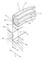
以下、本発明の詳細を図面に基づいて説明すると、図1および図2は、本発明の第1実施形態を示すもので、図1は、第1実施形態に係る軸受ユニットの軸方向に沿った半断面図で、要部の拡大図を併記している。図2は、図1の軸受ユニットの要部の分解斜視図である。
【0019】
この第1実施形態は、本発明を、連続鋳造設備におけるピンチロールの支軸の中央部を支持する2つ割り型の軸受ユニットに実施したもので、図1中、符号1は、ピンチロールの支軸、2はハウジング、3は外輪、4は、内輪を一部として含む内輪体、5は、転動体としての円筒ころである。前記の各部材のうち、ハウジング2は上下2つに分割されており、外輪3と内輪体4とはそれぞれ2つ割り構造となっている。外輪3の軸方向外側で、ハウジング2の内周部には、ラビリンスリング21が取り付けられている。このラビリンスリング21は、ハウジング2より軸方向外方に張り出し、その張り出し端部は、この実施形態の軸受ユニットの軸方向両側に位置するローラの端面に形成された溝22内に挿入されている。
【0020】
外輪3は、球面座2aを介してハウジング2の内周部に設けられている。内輪体4は、内輪軌道面4aを有する内輪部4bと、この内輪部4bから軸方向(図1で、矢印イの方向)外方に張り出した締結部4cとを一体化したものである。内輪部4bと締結部4cとは、別部材として構成される場合もある。
【0021】
締結部4cは、内輪軌道面4aより大径で、その外周面はハウジング2の内周面に近接している。内輪軌道面4aの軸方向両外側で、締結部4cの外周部にはそれぞれ周溝6が形成されている。これら周溝6は角溝であって、図2に明示するように、軸方向(矢印イの方向)とほぼ直交する内壁面6a,6bを有する。この周溝6には、シール部材として、オイルシール7が嵌め込みにより取り付けられている。
【0022】
オイルシール7は、環状で、周方向1個所に割れ目があり、この割れ目を中心に大径に拡開できるようになっている。このオイルシール7は、図2に拡大して示すように、ゴムのような弾性材で互いに一体に形成された弾性摺接部としてのリップ8と嵌め込み基部9とを有する。リップ8は、軸方向外方へ斜めに延出し、その先端部が外輪3側の部材であるラビリンスリング21の内周面に摺接するようになっている。嵌め込み基部9は、前記の周溝6内に嵌め込まれる部分で、周溝6の断面形状に応じて、断面がほぼ矩形に成形されている。この嵌め込み基部9には断面L字形の芯金10が一体的に接合されている。なお、オイルシール7の嵌め込み基部9の軸方向に沿った幅Wに対して、周溝6の軸方向に沿った幅Dは、同一もしくは若干広幅に設定されており、具体的には、最大で嵌め込み基部Wの幅より0.2mm広い幅となっている。
【0023】
この嵌め込み基部9の両側面(嵌め込み基部9の外面で、軸方向イとほぼ直交する面)のうち、軸方向外側の側面(芯金10とは反対側の側面で、図では右側の側面)9aには、凸部11がオイルシール7の全周にわたって形成されている。この凸部11は、嵌め込み基部9が周溝6内に嵌め込まれた状態では、周溝6の内壁面6aに圧接する部分である。そして、この凸部11の外径側で該凸部11に隣り合う位置に、受け入れ凹部12が前記凸部11と平行に、オイルシール7の全周にわたって形成されている。この受け入れ凹部12は、圧縮変形した凸部11を受け入れる部分である。
【0024】
上記構成において、この軸受ユニットの組み立てに当たっては、内輪側にある周溝6に、オイルシール7の嵌め込み基部9を嵌め込むのであるが、嵌め込み基部9の側面9aからは凸部11が突出しているから、嵌め込み基部9の側面9aの各部分のうち、凸部11に周溝6の内壁面6aとの接触圧が集中的に作用する。そのため、嵌め込み基部9の側面の全面が周溝6の内壁面6aに接触する場合に比べ、嵌め込み基部9の嵌め込みに対する抵抗が小さく、容易に嵌め込みができる。
【0025】
しかも、嵌め込み基部9の周溝6内への嵌め込みに伴い、凸部11は、圧縮されるとともに、外径側に折り畳まれるように変形して、その外径側にある受け入れ凹部12内に入り込む。このように、嵌め込み基部9では、凸部11の圧縮された分が受け入れ凹部12内に逃げることになり、周溝6の限られた空間内でも、凸部11を含む嵌め込み基部9の全体は柔軟に変形する。そのため、嵌め込み基部9は、抵抗の少ない状態で容易に周溝6の奥の所定深さまで嵌め込むことができる。
【0026】
さらに、オイルシール7の嵌め込み基部9を周溝6の内部に嵌め込んだ状態では、凸部11が受け入れ凹部12内に入り込むことで、嵌め込み基部9の側面9aが平坦化し、この平坦化した側面9aの全面がほぼ均等の接触圧で周溝6の内壁面6aに圧接する。また、嵌め込み基部9の他の側面9bも、凸部11の圧縮変形により、周溝6の対応する側面6bに圧接する。これで、嵌め込み基部9の両側面9a,9bと周溝6の内壁面6a,6bとの密着度が増し、高いシール性能の発揮する。
【0027】
また、図1に図示のように、凸部11が嵌め込み基部9の軸方向外側の側面9aに設けられている場合、その凸部11は、周溝6の内壁面6aとの間で、外径側に折り畳まれるように変形することで、その先端の向きが周溝6の開口に対して迎え角となる。凸部11はその変形形状により、外部から周溝6の内面に沿って水や異物が浸入することを確実に防止する。この点からも、高いシール性能が得られる。
【0028】
なお、図示の実施形態では、凸部11の断面形状をほぼ半円形としたが、これに限定されるものではなく、凸部11は断面角形に突出するものでもよく、また、外径側に折り畳み変形がしやすいように、外径側に斜めに突出するものであってもよい。受け入れ凹部12の断面形状は、凸部11の断面形状に応じて適宜設定されていればよい。
【0029】
このほか、図示の実施形態では、内輪軌道面4aの外側には、オイルシール7が1列設けられているだけであるが、グランドパッキン等、他のシール部材を併設して、多段でシールを行うようにしてもよい。また、図1の例では、オイルシール7のリップ8がラビリンスリング22の内周面に摺接しているが、リップ8がハウジング2の内周面もしくは外輪3の内周面に摺接するようにしてもよい。
【0030】
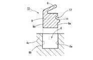
〔他の実施形態〕
周溝6に嵌め込みにより取り付けられるのは、第1実施形態に示すオイルシール7に限らず、図3ないし図5に示すようなシール部材でもよい。図3は、本発明の第2実施形態に係る軸受ユニットのオイルシールの断面図で、併せて周溝との関係を示している。この実施形態では、芯金を含まないオイルシール72が使用されている。すなわち、この実施形態のオイルシール72は、第1実施形態のオイルシール7と同様に、外輪3側の部材(ラビリンスリング21)の内周面に摺接するリップ8と、周溝6の内部に嵌め込まれる嵌め込み基部9とを有するが、リップ8も嵌め込み基部9も、ともにゴムのような弾性材のみで成形されている。
【0031】
このオイルシール72の嵌め込み基部9の両側面9a,9bのうち、軸方向外側の側面9aに、凸部11がオイルシール72の全周にわたって形成されるとともに、この凸部11の外径側で該凸部11に隣り合う位置に、受け入れ凹部12が前記凸部11と平行にオイルシール72の全周にわたって形成されている点は、第1実施形態のオイルシール7と同じである。
【0032】
したがって、第1実施形態の場合と同様の作用効果が得られる。すなわち、(イ)凸部11に周溝6の内壁面6aとの接触圧が集中的に作用する、また、圧縮変形される凸部11が受け入れ凹部12内に入り込む、等の理由で、嵌め込み基部9の嵌め込みに対する抵抗が小さく、容易に嵌め込みができる、(ロ)嵌め込み基部9を周溝6の内部に嵌め込んだ状態では、嵌め込み基部9の側面9aが平坦化する等の理由で、嵌め込み基部9と周溝6との密着度が増し、高いシール性能の発揮する、(ハ)軸方向外方に突出する凸部11は、外径側に折り畳まれるように変形して、その変形形状により、外部からの水の浸入を確実に防止する、等の作用効果が得られる。
【0033】
図4は、本発明の第3実施形態に係る軸受ユニットのオイルシールの断面図で、併せて周溝との関係を示している。この実施形態のオイルシール73は、第1実施形態のオイルシール7と同様に、外輪3側の部材(ラビリンスリング21)の内周面に摺接するリップ8と、周溝6の内部に嵌め込まれる嵌め込み基部9とを有するが、嵌め込み基部9には芯金が含まれておらず、かつ、この嵌め込み基部9の両側面9a,9bに、それぞれ凸部11,13と凹部12,14とが形成されている。各側面9a,9bにおいて、凸部11,13がオイルシール73の全周にわたって形成されるとともに、受け入れ凹部12,14が、凸部11,13の外径側で該凸部11,13に隣り合う位置に、オイルシール73の全周にわたって形成されている。
【0034】
このように、オイルシール73の嵌め込み基部9の両側面9a,9bにそれぞれ凸部11,13と凹部12,14とが形成されていると、(ニ)各側面9a,9bでの凸部11,13の変形形状により、外部からの水の浸入や、潤滑剤の流出が確実に防止されるほか、(ホ)嵌め込み基部9の嵌め込みに対する抵抗が、両側面9a,9bの間で均等になるので、オイルシール73を傾けることなく、所定の姿勢で周溝6に取り付けることができる。
【0035】
もちろん、第1実施形態や第2実施形態について記した(イ)嵌め込み基部9の嵌め込みに対する抵抗が小さく、容易に嵌め込みができる、(ロ)周溝6内で嵌め込み基部9の側面が平坦化する等の理由で、嵌め込み基部9と周溝6との密着度が増し、高いシール性能を発揮する、等の作用効果を有することは、言うまでもない。
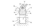
【0036】
図5は、本発明の第4実施形態に係る軸受ユニットのオイルシールの断面図で、併せて周溝との関係を示している。この実施形態では、オイルシール74は、複リップタイプで、2つのリップ81,82の間にガータスプリング15が設けられている。嵌め込み基部9には、その両側面9a,9bにそれぞれ凸部11,13と凹部12,14とが形成されている。各側面9a,9bにおいて、凸部11,13がオイルシール74の全周にわたって形成されるとともに、受け入れ凹部12,14が、凸部11,13の外径側で該凸部11,13に隣り合う位置にオイルシール74の全周にわたって形成されている点は、第3実施形態のオイルシール73の場合と同じである。
【0037】
この第4実施形態の構成では、第3実施形態の場合と同様に、(ニ)各側面9a,9bでの凸部11,13の変形形状により、外部からの水の浸入や、潤滑剤の流出が確実に防止されるほか、(ホ)嵌め込み基部9の嵌め込みに対する抵抗が、両側面9a,9bの間で均等になり、オイルシール74を傾けることなく周溝6に取り付けることができる、等の作用効果を有する。もちろん、(イ)嵌め込み基部9の嵌め込みに対する抵抗が小さく、容易に嵌め込みができる、(ロ)周溝6内で嵌め込み基部9の側面が平坦化する等の理由で、嵌め込み基部9と周溝6との密着度が増し、高いシール性能を発揮する、等の作用効果を有することは、言うまでもない。
【0038】
このほか、第1実施形態については、外輪3および内輪体4を2つ割りとしたが、本発明は、環状で周方向に連続した外輪、内輪もしくは内輪体を有する軸受ユニットにも実施しうる。オイルシール7等のシール部材は、第1実施形態で述べたように、周方向の少なくとも1個所に割れ目を有するものであってもよいが、全体が円環状のまま拡縮変形が可能である場合は、環状で周方向に連続したものであってもよい。
【0039】
【発明の効果】
本発明によれば、シール部材の嵌め込み基部を抵抗の少ない状態で、内輪側の周溝に嵌め込むことができ、取り付けに手間がかからず、軸受ユニットの組み立てが容易にできる。しかも、周溝に嵌め込み基部を嵌め込んだ状態では、凸部が外径側に折り畳まれるように変形して、その先端が周溝の開口側に対して迎え角となるので、外部からの水の浸入、もしくは潤滑剤の流出を確実に防止するほか、周溝内で嵌め込み基部の側面が平坦化する等して、周溝の内壁面に全面的に密着するので、高いシール効果が得られる。
【図面の簡単な説明】
【図1】本発明の第1実施形態に係る軸受ユニットの軸方向に沿った半断面図で、要部の拡大図を併記している。
【図2】図1の軸受ユニットの要部の分解斜視図である。
【図3】本発明の第2実施形態に係る軸受ユニットのオイルシールの断面図で、併せて周溝との関係を示している。
【図4】本発明の第3実施形態に係る軸受ユニットのオイルシールの断面図で、併せて周溝との関係を示している。
【図5】本発明の第4実施形態に係る軸受ユニットのオイルシールの断面図で、併せて周溝との関係を示している。
【符号の説明】
2 ハウジング
3 外輪
4 内輪体(内輪を含む部材)
5 円筒ころ(転動体)
6 周溝
6a,6b 周溝の内壁面
7 オイルシール(シール部材)
8 リップ
9 嵌め込み基部
9a,9b 嵌め込み基部の側面
11 凸部
12 受け入れ凹部[0001]
TECHNICAL FIELD OF THE INVENTION
The present invention relates to a bearing unit.
[0002]
[Prior art]
A pinch roll used in a continuous casting facility is supported at both ends and may be supported at a central portion because a large load is applied. In this case, a split bearing unit is used to support the center of the pinch roll due to assembly restrictions (see Patent Document 1).
[0003]
The conventional split type bearing unit includes a split outer ring, a split inner ring, a plurality of rolling elements disposed between the inner and outer rings, and an annular connection of the split inner ring. And is provided in a vertically split housing. In this bearing unit, the outer periphery of the inner ring or a member integral with the inner ring (a fastening ring in the example of Patent Document 1) is provided on the outer side in the axial direction of the inner ring raceway surface in order to retain the lubricant and to prevent water and dust. A groove is formed, and a seal member such as an oil seal is fitted into the peripheral groove by fitting. The seal member has a crack at least at one location in the circumferential direction, and can be expanded to a large diameter around the crack.
[0004]
[Patent Document 1]
Japanese Utility Model Publication No. 6-4098
[Problems to be solved by the invention]
By the way, in the bearing unit as described above, it is necessary to fit the oil seal into the circumferential groove in a state where the fitting base of the oil seal is compressed in order to strengthen the mounting state of the oil seal. However, at the time of the fitting, the side surface of the fitting base of the oil seal comes into full pressure contact with the inner wall surface of the circumferential groove, so that the resistance to the fitting is large, and the work of attaching the oil seal is not easy. It takes time to assemble the entire unit. If the mounting state of the oil seal is uncertain, the oil seal itself will fall off during use, or the lip of the oil seal will protrude more than necessary to the outer diameter side, and the protruding part will wear out early, etc. Occurs.
[0006]
On the other hand, when the oil seal is easily fitted into the circumferential groove by reducing the width of the fitting base of the oil seal, etc., the workability of the assembly is improved, but the fitting base of the oil seal and the circumferential groove are improved. , The water and foreign matter easily enter from the outside, and the sealing performance decreases.
[0007]
SUMMARY OF THE INVENTION The present invention has been made to solve the above-described problem, and has as its object to easily and reliably attach a seal member to a circumferential groove on the inner ring side without reducing sealing performance.
[0008]
[Means for Solving the Problems]
In order to achieve the above object, the inventor of the present invention has made various studies, and as a result, in the bearing unit, attempts have been made to form a protrusion on the side surface of the fitting base of the oil seal over the entire circumference. In this configuration, it is considered that the resistance when the oil seal is fitted into the circumferential groove is reduced.
[0009]
However, in the configuration in which the projection is simply provided on the fitting base of the oil seal, the fitting base including the projection is compressed in the limited space of the circumferential groove, so that there is little room for deformation, The resistance to fitting does not become too small. This drawback is more pronounced for larger ones, and the installation of a large-diameter oil seal requires considerable effort. On the other hand, if the fitting of the oil seal is facilitated by reducing the amount of protrusion of the convex portion or increasing the width of the circumferential groove, the sealing performance is reduced.
[0010]
The present invention has been made in view of the above circumstances, and has an outer ring, an inner ring rotatably supported on the outer ring via a rolling element, and an inner ring at an axially outer side of a raceway surface of the inner ring. Alternatively, a peripheral groove formed on an outer peripheral portion of a member integral with the inner ring and having an inner wall surface substantially perpendicular to the axial direction, and an elastic slide attached by fitting into the peripheral groove and slidingly contacting the inner peripheral surface of the member on the outer ring side A seal member having a contact portion, wherein the seal member has, on the side surface of the fitting base, a convex portion which is in pressure contact with the inner wall surface of the peripheral groove over the entire periphery of the seal member, and A bearing unit was formed on the outer diameter side, in which a receiving concave portion for receiving the compressed and deformed convex portion was formed.
[0011]
The "circumferential groove" in the above configuration includes not only a square groove having a U-shaped cross section but also a groove having a U-shaped cross section, and a groove having an inner wall surface substantially orthogonal to the axial direction of the bearing unit on both sides of the opening. Means
[0012]
In the above configuration, in assembling the bearing unit, the fitting base of the sealing member is fitted into the circumferential groove on the inner ring side. In this case, since the convex portion protrudes from the side surface of the fitting base, the convex portion contacts the inner wall surface of the circumferential groove with a large contact pressure, and the convex portion of the side surface of the fitting base portion contacts the inner surface of the circumferential groove. The contact pressure with is concentrated. Therefore, the resistance to the fitting of the fitting base is small, and the fitting can be easily performed.
[0013]
In addition, with the fitting of the fitting base into the circumferential groove, the convex portion is compressed and deforms so as to be folded toward the outer diameter side, and enters the receiving concave portion on the outer diameter side. As described above, in the fitting base, the compressed portion of the projection escapes into the receiving recess, and the entire fitting base including the projection is flexibly deformed even in the limited space of the circumferential groove. Therefore, the fitting base can be easily fitted to a predetermined depth deep in the circumferential groove with low resistance.
[0014]
Furthermore, in a state where the fitting base of the sealing member is fitted in the inside of the peripheral groove, the side face of the fitting base is flattened by the protrusion entering the receiving recess, and the entire surface of the flattened side is almost uniformly contacted. Since the pressure is applied to the inner wall surface of the peripheral groove by pressure, the degree of adhesion to the inner wall surface of the peripheral groove is increased, and high sealing performance is exhibited.
[0015]
The convex portion and the receiving concave portion on the outer diameter side may be formed on one side surface of the fitting base of the seal member, but when provided on the axially outer side surface of the fitting base, The convex portion protruding outward deforms so as to be folded toward the outer diameter side with the inner wall surface of the circumferential groove. Thereby, the direction of the tip of the projection becomes the angle of attack with respect to the opening side of the peripheral groove, so that it is possible to reliably prevent water or the like from entering along the inner surface of the peripheral groove from outside. When the projection is provided on the axially inner side surface of the fitting base, the deformed shape surely prevents the lubricant from flowing out from the inside of the bearing.
[0016]
When the convex portion and the concave portion are provided on both side surfaces of the fitting base of the sealing member, respectively, the deformed shape of the convex portion on each side surface allows intrusion of water from the outside and lubricant from the inside. Is reliably prevented from flowing out, and the resistance to the fitting of the fitting base is equal between the two side surfaces, so that the sealing member can be attached to the circumferential groove in a predetermined posture without tilting.
[0017]
The outer ring, the inner ring, and the seal member may all be annular and continuous in the circumferential direction, but the outer ring and the inner ring each have a split structure, and the seal member has at least a single fracture. In the case where it can be opened from the crack, for example, in a continuous casting facility, it can be suitably used as a split-type bearing unit that supports the center of a pinch roll.
[0018]
BEST MODE FOR CARRYING OUT THE INVENTION
[First Embodiment]
The details of the present invention will be described below with reference to the drawings. FIGS. 1 and 2 show a first embodiment of the present invention. FIG. 1 shows an axial direction of a bearing unit according to the first embodiment. In the half sectional view, an enlarged view of a main part is also shown. FIG. 2 is an exploded perspective view of a main part of the bearing unit of FIG.
[0019]
In the first embodiment, the present invention is applied to a split bearing unit that supports a central portion of a support shaft of a pinch roll in a continuous casting facility. In FIG. 1, reference numeral 1 denotes a pinch roll. The
[0020]
The outer ring 3 is provided on the inner peripheral portion of the
[0021]
The
[0022]
The
[0023]
Of the two side surfaces of the fitting base 9 (the outer surface of the
[0024]
In the above configuration, when assembling the bearing unit, the
[0025]
In addition, as the
[0026]
Further, in a state where the
[0027]
In addition, as shown in FIG. 1, when the
[0028]
In the illustrated embodiment, the cross-sectional shape of the
[0029]
In addition, in the illustrated embodiment, only one line of the
[0030]
[Other embodiments]
What is fitted into the
[0031]
Of the two
[0032]
Therefore, the same operation and effect as in the first embodiment can be obtained. That is, (a) the contact pressure with the
[0033]
FIG. 4 is a sectional view of an oil seal of a bearing unit according to a third embodiment of the present invention, and also shows a relationship with a circumferential groove. The
[0034]
As described above, when the
[0035]
Of course, the resistance to the fitting of the
[0036]
FIG. 5 is a sectional view of an oil seal of a bearing unit according to a fourth embodiment of the present invention, and also shows a relationship with a circumferential groove. In this embodiment, the
[0037]
In the configuration of the fourth embodiment, as in the case of the third embodiment, (d) the intrusion of water from the outside and the introduction of lubricant by the deformed shape of the
[0038]
In addition, in the first embodiment, the outer race 3 and the
[0039]
【The invention's effect】
ADVANTAGE OF THE INVENTION According to this invention, the fitting base of a sealing member can be fitted in the peripheral groove of an inner ring side with little resistance, installation does not take time, and assembly of a bearing unit can be facilitated. Moreover, when the base is fitted into the circumferential groove, the convex portion is deformed so as to be folded toward the outer diameter side, and the tip thereof has an angle of attack with respect to the opening side of the circumferential groove. In addition to preventing the infiltration of the lubricant or the outflow of the lubricant, the fitting surface is flattened in the circumferential groove, and the entire surface is in close contact with the inner wall surface of the circumferential groove, so that a high sealing effect is obtained. .
[Brief description of the drawings]
FIG. 1 is a half sectional view along an axial direction of a bearing unit according to a first embodiment of the present invention, and also shows an enlarged view of a main part.
FIG. 2 is an exploded perspective view of a main part of the bearing unit of FIG.
FIG. 3 is a cross-sectional view of an oil seal of a bearing unit according to a second embodiment of the present invention, and also shows a relationship with a circumferential groove.
FIG. 4 is a sectional view of an oil seal of a bearing unit according to a third embodiment of the present invention, and also shows a relationship with a circumferential groove.
FIG. 5 is a sectional view of an oil seal of a bearing unit according to a fourth embodiment of the present invention, and also shows a relationship with a circumferential groove.
[Explanation of symbols]
2 Housing 3
5 Cylindrical rollers (rolling elements)
6
8
Claims (3)
Translated fromJapanese前記シール部材には、その嵌め込み基部の側面に、前記周溝の内壁面に圧接する凸部がシール部材の全周にわたって形成されるとともに、前記凸部の外径側に、圧縮変形した前記凸部を受け入れる受け入れ凹部が形成されていることを特徴とする軸受ユニット。An outer ring, an inner ring rotatably supported by the outer ring via a rolling element, and an outer ring formed on an inner ring or an outer peripheral portion of an integral member with the inner ring at an axially outer side of a raceway surface of the inner ring, and being substantially orthogonal to the axial direction. A peripheral groove having an inner wall surface, and a sealing member having an elastic sliding contact portion attached to the peripheral groove by being fitted into the peripheral groove and slidingly contacting the inner peripheral surface of the outer ring side member;
On the side surface of the fitting base portion, a convex portion that presses against the inner wall surface of the peripheral groove is formed over the entire circumference of the seal member, and the convex portion that is compressed and deformed is formed on the outer diameter side of the convex portion. A bearing unit, wherein a receiving recess for receiving a portion is formed.
前記シール部材の嵌め込み基部の両側面に、それぞれ前記凸部と前記凹部とが形成されている軸受ユニット。The bearing unit according to claim 1,
A bearing unit in which the convex portion and the concave portion are respectively formed on both side surfaces of a fitting base of the seal member.
前記外輪と前記内輪とはいずれも2つ割り構造で、かつシール部材は、少なくとも単一の割れ目を有しその割れ目から拡開可能である軸受ユニット。In the bearing unit according to claim 1 or 2,
A bearing unit wherein each of the outer race and the inner race has a split structure, and the seal member has at least a single split and can be expanded from the split.
Priority Applications (1)
| Application Number | Priority Date | Filing Date | Title |
|---|---|---|---|
| JP2003073461AJP4140411B2 (en) | 2003-03-18 | 2003-03-18 | Bearing unit for continuous casting equipment |
Applications Claiming Priority (1)
| Application Number | Priority Date | Filing Date | Title |
|---|---|---|---|
| JP2003073461AJP4140411B2 (en) | 2003-03-18 | 2003-03-18 | Bearing unit for continuous casting equipment |
Publications (2)
| Publication Number | Publication Date |
|---|---|
| JP2004278738Atrue JP2004278738A (en) | 2004-10-07 |
| JP4140411B2 JP4140411B2 (en) | 2008-08-27 |
Family
ID=33289355
Family Applications (1)
| Application Number | Title | Priority Date | Filing Date |
|---|---|---|---|
| JP2003073461AExpired - Fee RelatedJP4140411B2 (en) | 2003-03-18 | 2003-03-18 | Bearing unit for continuous casting equipment |
Country Status (1)
| Country | Link |
|---|---|
| JP (1) | JP4140411B2 (en) |
Cited By (4)
| Publication number | Priority date | Publication date | Assignee | Title |
|---|---|---|---|---|
| JP2007040519A (en)* | 2005-07-04 | 2007-02-15 | Nsk Ltd | Split type rolling bearing unit |
| US7789567B2 (en)* | 2006-08-30 | 2010-09-07 | Honeywell International Inc. | Bearing with fluid flow bypass |
| WO2014094755A1 (en)* | 2012-12-20 | 2014-06-26 | Schaeffler Technologies AG & Co. KG | Bearing |
| WO2024009459A1 (en)* | 2022-07-07 | 2024-01-11 | 株式会社ジェイテクト | Rolling bearing device |
Families Citing this family (2)
| Publication number | Priority date | Publication date | Assignee | Title |
|---|---|---|---|---|
| JP6227250B2 (en)* | 2013-01-10 | 2017-11-08 | Ntn株式会社 | Bearing seals and rolling bearings with seals |
| EP2853351B1 (en)* | 2013-09-27 | 2019-12-25 | Aktiebolaget SKF | Rotative assembly, method for dismounting a sealing element and extraction tool for dismounting a sealing element |
Citations (10)
| Publication number | Priority date | Publication date | Assignee | Title |
|---|---|---|---|---|
| JPS5998163U (en)* | 1982-12-23 | 1984-07-03 | 三菱電線工業株式会社 | One-way sealing gasket |
| JPS62196254U (en)* | 1986-06-02 | 1987-12-14 | ||
| JPH066751U (en)* | 1992-06-30 | 1994-01-28 | エヌティエヌ株式会社 | Sealing device for split rolling bearings |
| JPH0626077A (en)* | 1992-07-08 | 1994-02-01 | Hitachi Constr Mach Co Ltd | Seal for turning wheel |
| JPH064098Y2 (en)* | 1987-04-01 | 1994-02-02 | 光洋精工株式会社 | Split type rotary bearing unit |
| JPH0925939A (en)* | 1995-07-14 | 1997-01-28 | Nippon Thompson Co Ltd | Sealed bearing |
| JPH10217996A (en)* | 1997-02-04 | 1998-08-18 | Koyo Seiko Co Ltd | Rack pinion type steering device |
| JPH1193197A (en)* | 1997-09-24 | 1999-04-06 | Hitachi Constr Mach Co Ltd | Bearing unit |
| JP2000002255A (en)* | 1998-06-12 | 2000-01-07 | Nok Corp | Sealing device |
| JP2001227553A (en)* | 2000-02-16 | 2001-08-24 | Ntn Corp | Super-thin-walled type rolling bearing |
- 2003
- 2003-03-18JPJP2003073461Apatent/JP4140411B2/ennot_activeExpired - Fee Related
Patent Citations (10)
| Publication number | Priority date | Publication date | Assignee | Title |
|---|---|---|---|---|
| JPS5998163U (en)* | 1982-12-23 | 1984-07-03 | 三菱電線工業株式会社 | One-way sealing gasket |
| JPS62196254U (en)* | 1986-06-02 | 1987-12-14 | ||
| JPH064098Y2 (en)* | 1987-04-01 | 1994-02-02 | 光洋精工株式会社 | Split type rotary bearing unit |
| JPH066751U (en)* | 1992-06-30 | 1994-01-28 | エヌティエヌ株式会社 | Sealing device for split rolling bearings |
| JPH0626077A (en)* | 1992-07-08 | 1994-02-01 | Hitachi Constr Mach Co Ltd | Seal for turning wheel |
| JPH0925939A (en)* | 1995-07-14 | 1997-01-28 | Nippon Thompson Co Ltd | Sealed bearing |
| JPH10217996A (en)* | 1997-02-04 | 1998-08-18 | Koyo Seiko Co Ltd | Rack pinion type steering device |
| JPH1193197A (en)* | 1997-09-24 | 1999-04-06 | Hitachi Constr Mach Co Ltd | Bearing unit |
| JP2000002255A (en)* | 1998-06-12 | 2000-01-07 | Nok Corp | Sealing device |
| JP2001227553A (en)* | 2000-02-16 | 2001-08-24 | Ntn Corp | Super-thin-walled type rolling bearing |
Cited By (5)
| Publication number | Priority date | Publication date | Assignee | Title |
|---|---|---|---|---|
| JP2007040519A (en)* | 2005-07-04 | 2007-02-15 | Nsk Ltd | Split type rolling bearing unit |
| US7789567B2 (en)* | 2006-08-30 | 2010-09-07 | Honeywell International Inc. | Bearing with fluid flow bypass |
| WO2014094755A1 (en)* | 2012-12-20 | 2014-06-26 | Schaeffler Technologies AG & Co. KG | Bearing |
| US9581201B2 (en) | 2012-12-20 | 2017-02-28 | Schaeffler Technologies AG & Co. KG | Bearing |
| WO2024009459A1 (en)* | 2022-07-07 | 2024-01-11 | 株式会社ジェイテクト | Rolling bearing device |
Also Published As
| Publication number | Publication date |
|---|---|
| JP4140411B2 (en) | 2008-08-27 |
Similar Documents
| Publication | Publication Date | Title |
|---|---|---|
| JPH10252762A (en) | Sealing device for rolling bearings | |
| JP2009540253A (en) | Rolling bearing with sealing device for sealing two inner races and a separate seam between inner races | |
| US8226298B2 (en) | Sealing device and rolling bearing apparatus | |
| JP2010190241A (en) | Self-aligning roller bearing | |
| JP2004278738A (en) | Bearing unit | |
| CN113508240B (en) | Rolling bearing | |
| JP4465755B2 (en) | Rolling bearing with sealing plate | |
| JP2002206550A (en) | Sealing device for rolling bearings | |
| JP2003269616A (en) | sticker | |
| JP6981143B2 (en) | Ball bearing with seal | |
| JP2015161405A (en) | Rolling bearing with sealing device | |
| JP2005320983A (en) | Rolling bearing | |
| JP4649811B2 (en) | Sealing device | |
| JP2010090986A (en) | Sealed rolling bearing | |
| JP2005054827A (en) | Sealing device | |
| JP4506262B2 (en) | Sealing means for rolling bearing unit Rolling bearing unit | |
| JP2000145799A (en) | Sealing device for rolling bearing and highly sludgeresistant rolling bearing | |
| JP4545468B2 (en) | Sealing device | |
| JP4417190B2 (en) | Sealing device | |
| JP2005282669A (en) | Rolling bearing sealing device | |
| JPH08159164A (en) | Rolling bearing with seal | |
| JP2020143708A (en) | Thrust bearing | |
| JP2001304424A (en) | Sealing device for axle support bearings of railway vehicles | |
| JP4203712B2 (en) | Rolling bearing | |
| JP2002188652A (en) | Rolling bearing |
Legal Events
| Date | Code | Title | Description |
|---|---|---|---|
| A621 | Written request for application examination | Free format text:JAPANESE INTERMEDIATE CODE: A621 Effective date:20060215 | |
| A977 | Report on retrieval | Free format text:JAPANESE INTERMEDIATE CODE: A971007 Effective date:20070731 | |
| A131 | Notification of reasons for refusal | Free format text:JAPANESE INTERMEDIATE CODE: A131 Effective date:20070808 | |
| A521 | Request for written amendment filed | Free format text:JAPANESE INTERMEDIATE CODE: A523 Effective date:20070928 | |
| A02 | Decision of refusal | Free format text:JAPANESE INTERMEDIATE CODE: A02 Effective date:20080205 | |
| A521 | Request for written amendment filed | Free format text:JAPANESE INTERMEDIATE CODE: A523 Effective date:20080229 | |
| A911 | Transfer to examiner for re-examination before appeal (zenchi) | Free format text:JAPANESE INTERMEDIATE CODE: A911 Effective date:20080409 | |
| TRDD | Decision of grant or rejection written | ||
| A01 | Written decision to grant a patent or to grant a registration (utility model) | Free format text:JAPANESE INTERMEDIATE CODE: A01 Effective date:20080520 | |
| A01 | Written decision to grant a patent or to grant a registration (utility model) | Free format text:JAPANESE INTERMEDIATE CODE: A01 | |
| A61 | First payment of annual fees (during grant procedure) | Free format text:JAPANESE INTERMEDIATE CODE: A61 Effective date:20080602 | |
| FPAY | Renewal fee payment (event date is renewal date of database) | Free format text:PAYMENT UNTIL: 20110620 Year of fee payment:3 | |
| R150 | Certificate of patent or registration of utility model | Ref document number:4140411 Country of ref document:JP Free format text:JAPANESE INTERMEDIATE CODE: R150 Free format text:JAPANESE INTERMEDIATE CODE: R150 | |
| FPAY | Renewal fee payment (event date is renewal date of database) | Free format text:PAYMENT UNTIL: 20120620 Year of fee payment:4 | |
| FPAY | Renewal fee payment (event date is renewal date of database) | Free format text:PAYMENT UNTIL: 20120620 Year of fee payment:4 | |
| FPAY | Renewal fee payment (event date is renewal date of database) | Free format text:PAYMENT UNTIL: 20130620 Year of fee payment:5 | |
| LAPS | Cancellation because of no payment of annual fees |