JP2004275782A - Controller for injection device - Google Patents
Controller for injection deviceDownload PDFInfo
- Publication number
- JP2004275782A JP2004275782AJP2004164810AJP2004164810AJP2004275782AJP 2004275782 AJP2004275782 AJP 2004275782AJP 2004164810 AJP2004164810 AJP 2004164810AJP 2004164810 AJP2004164810 AJP 2004164810AJP 2004275782 AJP2004275782 AJP 2004275782A
- Authority
- JP
- Japan
- Prior art keywords
- plunger
- syringe
- injection
- motor
- display
- Prior art date
- Legal status (The legal status is an assumption and is not a legal conclusion. Google has not performed a legal analysis and makes no representation as to the accuracy of the status listed.)
- Granted
Links
- 238000002347injectionMethods0.000titleclaimsabstractdescription119
- 239000007924injectionSubstances0.000titleclaimsabstractdescription119
- 239000012530fluidSubstances0.000claimsabstractdescription14
- 241001465754MetazoaSpecies0.000claimsabstractdescription5
- 239000004606Fillers/ExtendersSubstances0.000claimsdescription10
- 239000000243solutionSubstances0.000abstract1
- 238000004891communicationMethods0.000description16
- 229940071643prefilled syringeDrugs0.000description16
- 238000003825pressingMethods0.000description16
- 238000012545processingMethods0.000description11
- 230000006870functionEffects0.000description10
- 238000000034methodMethods0.000description10
- 230000000994depressogenic effectEffects0.000description7
- 238000010586diagramMethods0.000description7
- 230000008569processEffects0.000description7
- 239000002872contrast mediaSubstances0.000description6
- 238000009987spinningMethods0.000description6
- 230000001133accelerationEffects0.000description5
- 239000000872bufferSubstances0.000description5
- 238000001514detection methodMethods0.000description5
- 230000008859changeEffects0.000description4
- 230000000694effectsEffects0.000description4
- 230000003287optical effectEffects0.000description4
- 230000004044responseEffects0.000description4
- 238000005516engineering processMethods0.000description3
- 238000002360preparation methodMethods0.000description3
- 230000007704transitionEffects0.000description3
- 239000004020conductorSubstances0.000description2
- 229940039231contrast mediaDrugs0.000description2
- 208000015181infectious diseaseDiseases0.000description2
- 239000004973liquid crystal related substanceSubstances0.000description2
- 230000007257malfunctionEffects0.000description2
- 238000012360testing methodMethods0.000description2
- 238000013519translationMethods0.000description2
- 240000002317Camassia leichtliniiSpecies0.000description1
- 235000000459Camassia leichtliniiNutrition0.000description1
- 241001522296Erithacus rubeculaSpecies0.000description1
- 230000005355Hall effectEffects0.000description1
- 210000001015abdomenAnatomy0.000description1
- 244000145845chatteringSpecies0.000description1
- 238000006243chemical reactionMethods0.000description1
- 230000006872improvementEffects0.000description1
- 210000004185liverAnatomy0.000description1
- 238000012986modificationMethods0.000description1
- 230000004048modificationEffects0.000description1
- 238000012544monitoring processMethods0.000description1
- 230000002093peripheral effectEffects0.000description1
- 230000005855radiationEffects0.000description1
- 239000004065semiconductorSubstances0.000description1
- 239000007787solidSubstances0.000description1
- 230000001360synchronised effectEffects0.000description1
- 230000001960triggered effectEffects0.000description1
- 230000000007visual effectEffects0.000description1
Images


Classifications
- A—HUMAN NECESSITIES
- A61—MEDICAL OR VETERINARY SCIENCE; HYGIENE
- A61M—DEVICES FOR INTRODUCING MEDIA INTO, OR ONTO, THE BODY; DEVICES FOR TRANSDUCING BODY MEDIA OR FOR TAKING MEDIA FROM THE BODY; DEVICES FOR PRODUCING OR ENDING SLEEP OR STUPOR
- A61M5/00—Devices for bringing media into the body in a subcutaneous, intra-vascular or intramuscular way; Accessories therefor, e.g. filling or cleaning devices, arm-rests
- A61M5/14—Infusion devices, e.g. infusing by gravity; Blood infusion; Accessories therefor
- A61M5/142—Pressure infusion, e.g. using pumps
- A61M5/145—Pressure infusion, e.g. using pumps using pressurised reservoirs, e.g. pressurised by means of pistons
- A61M5/1452—Pressure infusion, e.g. using pumps using pressurised reservoirs, e.g. pressurised by means of pistons pressurised by means of pistons
- A61M5/14546—Front-loading type injectors
- A—HUMAN NECESSITIES
- A61—MEDICAL OR VETERINARY SCIENCE; HYGIENE
- A61M—DEVICES FOR INTRODUCING MEDIA INTO, OR ONTO, THE BODY; DEVICES FOR TRANSDUCING BODY MEDIA OR FOR TAKING MEDIA FROM THE BODY; DEVICES FOR PRODUCING OR ENDING SLEEP OR STUPOR
- A61M5/00—Devices for bringing media into the body in a subcutaneous, intra-vascular or intramuscular way; Accessories therefor, e.g. filling or cleaning devices, arm-rests
- A61M5/14—Infusion devices, e.g. infusing by gravity; Blood infusion; Accessories therefor
- A61M5/168—Means for controlling media flow to the body or for metering media to the body, e.g. drip meters, counters ; Monitoring media flow to the body
- A61M5/172—Means for controlling media flow to the body or for metering media to the body, e.g. drip meters, counters ; Monitoring media flow to the body electrical or electronic
- A—HUMAN NECESSITIES
- A61—MEDICAL OR VETERINARY SCIENCE; HYGIENE
- A61M—DEVICES FOR INTRODUCING MEDIA INTO, OR ONTO, THE BODY; DEVICES FOR TRANSDUCING BODY MEDIA OR FOR TAKING MEDIA FROM THE BODY; DEVICES FOR PRODUCING OR ENDING SLEEP OR STUPOR
- A61M2205/00—General characteristics of the apparatus
- A61M2205/60—General characteristics of the apparatus with identification means
- A61M2205/6027—Electric-conductive bridges closing detection circuits, with or without identifying elements, e.g. resistances, zener-diodes
- A—HUMAN NECESSITIES
- A61—MEDICAL OR VETERINARY SCIENCE; HYGIENE
- A61M—DEVICES FOR INTRODUCING MEDIA INTO, OR ONTO, THE BODY; DEVICES FOR TRANSDUCING BODY MEDIA OR FOR TAKING MEDIA FROM THE BODY; DEVICES FOR PRODUCING OR ENDING SLEEP OR STUPOR
- A61M5/00—Devices for bringing media into the body in a subcutaneous, intra-vascular or intramuscular way; Accessories therefor, e.g. filling or cleaning devices, arm-rests
- A61M5/14—Infusion devices, e.g. infusing by gravity; Blood infusion; Accessories therefor
- A61M5/142—Pressure infusion, e.g. using pumps
- A61M5/145—Pressure infusion, e.g. using pumps using pressurised reservoirs, e.g. pressurised by means of pistons
- A61M5/1452—Pressure infusion, e.g. using pumps using pressurised reservoirs, e.g. pressurised by means of pistons pressurised by means of pistons
- A61M5/14566—Pressure infusion, e.g. using pumps using pressurised reservoirs, e.g. pressurised by means of pistons pressurised by means of pistons with a replaceable reservoir for receiving a piston rod of the pump
- A—HUMAN NECESSITIES
- A61—MEDICAL OR VETERINARY SCIENCE; HYGIENE
- A61M—DEVICES FOR INTRODUCING MEDIA INTO, OR ONTO, THE BODY; DEVICES FOR TRANSDUCING BODY MEDIA OR FOR TAKING MEDIA FROM THE BODY; DEVICES FOR PRODUCING OR ENDING SLEEP OR STUPOR
- A61M5/00—Devices for bringing media into the body in a subcutaneous, intra-vascular or intramuscular way; Accessories therefor, e.g. filling or cleaning devices, arm-rests
- A61M5/44—Devices for bringing media into the body in a subcutaneous, intra-vascular or intramuscular way; Accessories therefor, e.g. filling or cleaning devices, arm-rests having means for cooling or heating the devices or media
- A61M5/445—Devices for bringing media into the body in a subcutaneous, intra-vascular or intramuscular way; Accessories therefor, e.g. filling or cleaning devices, arm-rests having means for cooling or heating the devices or media the media being heated in the reservoir, e.g. warming bloodbags
Landscapes
- Health & Medical Sciences (AREA)
- Vascular Medicine (AREA)
- Engineering & Computer Science (AREA)
- Anesthesiology (AREA)
- Biomedical Technology (AREA)
- Heart & Thoracic Surgery (AREA)
- Hematology (AREA)
- Life Sciences & Earth Sciences (AREA)
- Animal Behavior & Ethology (AREA)
- General Health & Medical Sciences (AREA)
- Public Health (AREA)
- Veterinary Medicine (AREA)
- Infusion, Injection, And Reservoir Apparatuses (AREA)
- Feeding And Watering For Cattle Raising And Animal Husbandry (AREA)
- Catching Or Destruction (AREA)
- Fluid-Pressure Circuits (AREA)
Abstract
Description
Translated fromJapanese本発明は、動物へ流体を注射するための注射装置のコントローラに関し、1992年5月11日に出願され、本願出願人に譲渡された米国特許出願第07/881,782号、発明の名称「動物に流体を注射するための方法および装置、およびそれに使用される使い捨てフロント装着可能な注射器」、発明者チャールズ・エス・ネアー外、と関連がある。 The present invention relates to a controller for an injection device for injecting a fluid into an animal, and relates to U.S. Patent Application No. 07 / 881,782, filed May 11, 1992 and assigned to the present applicant, entitled "Animal Methods and Apparatus for Injecting Fluids and the Disposable Front-Wappable Syringes Used Therewith ", Outside Charles S. Nehr.
注射装置(インジェクタ)は流体、例えばX線像または磁気像を増感するのに使用される、放射線に半透明な媒体(コントラスト流体)を注射器からチューブを介して、動物の被検体に注射する装置である。注射装置には、一般に注射ユニットが設けられ、このユニットはプランジャ駆動装置を有するスタンドすなわち支持体に調節自在に固定され、プランジャ駆動装置は注射器のプランジャに結合され、プランジャを前方に移動させ、流体をチューブ内に押し込んだり、プランジャを後方に移動させ、流体を注射器内に吸引して注射器を満たすことができる。 An injection device (injector) injects a translucent medium for radiation (contrast fluid), which is used to sensitize a fluid, for example, an X-ray image or a magnetic image, from a syringe through a tube to an animal subject. Device. The injection device is generally provided with an injection unit, which is adjustably secured to a stand or support having a plunger drive, the plunger drive being coupled to the plunger of the syringe to move the plunger forward and to move the fluid. Can be pushed into the tube or the plunger can be moved backwards to draw fluid into the syringe to fill the syringe.
注射装置は、被検体に注射される流体の注射レートおよび量を制御するように、プランジャ駆動装置を制御するための制御回路を含む。一般に制御回路は一つ以上の手動(マニュアル)スイッチを含み、この手動スイッチはユーザーが手動でプランジャ駆動装置を作動させ、プランジャを注射器の内外に移動させることができるようにする。一般にユーザーはプランジャを前方方向に移動させるには、前進駆動スイッチを押し続け、一方、後方にプランジャを移動させるには後進駆動スイッチを押し続けるようになっている。 The injection device includes a control circuit for controlling the plunger drive to control the injection rate and volume of the fluid injected into the subject. Generally, the control circuit includes one or more manual switches, which allow the user to manually activate the plunger drive and move the plunger into and out of the syringe. Generally, the user keeps pushing the forward drive switch to move the plunger in the forward direction, and keeps pushing the backward drive switch to move the plunger backward.
一般的な注射にでは、感染の危険を少なくするため、注射器は一回しか使用されず、使用後は廃棄される。あるケースでは、注射器は空の状態で注射装置に挿入される。この空の注射器は、注射器の内部が注射器のノズルと媒体供給部との間に接続された注射用チューブを介して、コントラスト流体の供給部に連通した状態で、プランジャを後退させることにより、内部に充填される。次に注射器から気泡が除かれ、注射を行う。注射の終了時には、注射器のプランジャはプランジャ駆動装置と同じように一般に前進している。 In a typical injection, the syringe is used only once to reduce the risk of infection and is discarded after use. In some cases, the syringe is inserted empty into the injection device. The empty syringe is retracted by retracting the plunger while the interior of the syringe is in communication with the supply of contrast fluid via an injection tube connected between the syringe nozzle and the media supply. Is filled. The air bubbles are then removed from the syringe and the injection is made. At the end of the injection, the plunger of the syringe is generally advanced, similar to the plunger drive.
ある注射装置では、プランジャ駆動装置が完全に後退している状態でしか、注射器を除いたり交換したりすることはできない。図1Aに示すように、空の注射器10には殺菌された空気が充填されており、プランジャ12は図示するような完全に後退した位置にある。プランジャ駆動装置はプランジャが完全に後退した位置にある状態で、プランジャの背面に設けられたボタン14に係合したりはずれたりするようになっているジョー18を含む。新しい空の注射器を充填する前は、プランジャを後方に後退させることにより、注射器に充填できるように、プランジャを注射器内で完全に前方に移動させる必要がある。従って、注射器の取り外しおよび交換が可能なように、プランジャ駆動装置を完全に後退させ、次にプランジャ駆動装置およびプランジャを完全に前進させ、注射器から空気を押しだし、次にプランジャ駆動装置およびプランジャを後退させて注射器を充填させることにより再装着作業が可能である。これらの長く、手動によるプランジャーの移動は、時間がかかる作業である。 In some injection devices, the syringe can only be removed or replaced with the plunger drive fully retracted. As shown in FIG. 1A, the empty syringe 10 is filled with sterile air and the
上記米国特許出願は、プランジャが完全に後退されていなくても、注射器を交換できるフロントローディング(装着)式注射装置を開示している。この注射装置は新しい注射をするための注射器を準備するために必要なプランジャの移動回数をかなり少なくし、注射をした後は、完全に前進した位置から駆動装置を移動することなく、注射器を取り除き、交換できるようになっている。(プランジャ駆動ジョー20は、プランジャの位置に係わらずボタン14と係合したりはずれたりすることができる。)注射器を交換した後は、駆動装置は格納され、次の注射のための注射器を充填できる。従って次の注射のために注射装置の準備をするには、プランジャ駆動装置を3回でなくて、1回移動するだけでよい。 The U.S. patent application discloses a front-loading injection device that allows the syringe to be replaced without the plunger being fully retracted. This injection device significantly reduces the number of plunger movements required to prepare the syringe for a new injection, and removes the syringe after the injection without moving the drive from the fully advanced position. , Can be replaced. (Plunger drive jaw 20 can engage and disengage
他の最近の改良点は、予め充填された使い捨て注射器を使用することである。この予め充填された注射器も、次回の注射のために注射装置の準備をするに必要な手動のプランジャの移動回数を減らす。注射の後に、プランジャ駆動装置を格納し、使用済み注射器を取り外し、次の充填済み注射器と交換し、次の注射のために注射装置の準備をする。よって、この場合も、プランジャ駆動装置を3回でなくて1回だけ手動で移動するだけでよい。 Another recent improvement is the use of pre-filled disposable syringes. This pre-filled syringe also reduces the number of manual plunger movements required to prepare the injection device for the next injection. After the injection, retract the plunger drive, remove the used syringe, replace it with the next filled syringe, and prepare the injection device for the next injection. Therefore, also in this case, the plunger driving device need only be manually moved once instead of three times.
感染を防止するため、注射後に注射器内に残留しているコントラスト媒体を廃棄しなければならない。しかしながらコントラスト媒体は比較的高価である。この理由から、注射の準備をする際は、次の注射に必要な量の媒体だけを空の注射器に充填する。同じ理由から、注射の準備をするオペレータが注射に必要な量の媒体だけを含む注射器を選択できるように、種々の容量、例えば60ml〜125mlまでの範囲の容量の、予め充填された注射器が販売されている。 The contrast medium remaining in the syringe after the injection must be discarded to prevent infection. However, contrast media is relatively expensive. For this reason, when preparing for an injection, the empty syringe is filled with only the required amount of medium for the next injection. For the same reason, pre-filled syringes of various volumes, for example volumes ranging from 60 ml to 125 ml, are sold so that the operator preparing for the injection can select a syringe containing only the required amount of medium for the injection. Have been.
図1Bに代表的な予め充填された注射器が示されている。多くの点で予め充填された注射器は図1に示した空の注射器と同じである。双方の注射器では、バレル10およびプランジャ12は、同じ大きさで同じ形状となっている(現在使用されている注射装置は、わずか数種の、FDAで認可された注射器の寸法、すなわち200mlサイズおよび125mlサイズに合致しているだけで、すべての注射器はこれらの寸法を使用している)。更に双方の注射器は最初バレル10の端部に位置するボタン14を有している(従って双方の注射器は注射器の端部のボタンを把持するようになっている注射装置とコンパーチブルである)。主な違いは、図1Bの予め充填された注射器では、プランジャ12の最初の位置が注射器の中間にあることである(従って予め充填された注射器の初期容量は少なくなっている)。プランジャのボタン14にはイクステンダー16を取り付け、注射器の端部に注射装置によりグリップできる第2ボタン18を形成している。 An exemplary pre-filled syringe is shown in FIG. 1B. In many respects, the pre-filled syringe is the same as the empty syringe shown in FIG. In both syringes, barrel 10 and
上記のように、現在の技術レベルでは、注射を行うよう注射装置の準備をするには、注射器のバレルの内外にプランジャの駆動装置を手動で少なくとも1回移動し、かかる移動を3回行わなければならない。かかる作業は時間がかかるだけでなく、オペレータがかかる移動を行うのに手動の移動スイッチを押し続けなければならず、よって注射装置に物理的に縛り付けられ、他の準備を行うのに、この作業時間を割くことはできないので、手間がかかり、非効率的である。 As noted above, at the current state of the art, to prepare an injection device for injection, the plunger drive must be manually moved at least once in and out of the barrel of the syringe and three such movements must be performed. Must. Such an operation is not only time consuming, but also requires the operator to keep pressing the manual movement switch to make such a movement, thus being physically tied to the injection device and making other preparations. It is time-consuming, inefficient, and time-consuming.
本発明の一実施例によれば、プランジャ駆動コントローラはロックモードを有し、このロックモードでは手動移動スイッチを押すことにより、最初リクエストした移動がオペレータがスイッチを押し続けているか否かに係わらず続き、この移動はプランジャ駆動装置が完全前進位置または完全後退位置に達するまで続く。従って、一旦コントローラがロックモードに入れば、オペレータは手動スイッチを解放してもよく、オペレータが次の注射のための他の準備をしながら所望の移動(前進または後進)が続く。 According to one embodiment of the present invention, the plunger drive controller has a lock mode in which pressing the manual movement switch allows the originally requested movement to be performed regardless of whether the operator continues to press the switch. This movement continues until the plunger drive reaches a fully advanced position or a fully retracted position. Thus, once the controller has entered the lock mode, the operator may release the manual switch and the desired movement (forward or reverse) continues while the operator makes other preparations for the next injection.
好ましい実施例では、オペレータは所定の時間の間手動移動スイッチを押すことによりコントローラをロックモードに入れる。安全のため、手動移動スイッチは2つのボタンから構成され、これら2つのボタンは移動を行わせるには同時に押さなければならない。移動は双方のボタンを押すことにより開始される。双方のボタンは押され続けると、プランジャ駆動は速度が最大値に達し、プランジャ駆動コントローラがロックモードとなるまで移動速度を速める。コントローラが最大速度に達し、ロックモードとなる前に、一方のボタンが解放されると移動が続くが、一定速度となる。第2ボタンが解放されれば移動は停止する。これとは異なり、コントローラが最大速度に達し、ロックモードになれば、双方のボタンが解放されても移動が続くが、その後、いずれかのボタンが押されると、移動が停止する。コントローラは例えば移動中点滅し、コントローラがロックモードに入ると定常的に光るライトにより視覚的なフィードバックを行うこともできる。このライト自体は、移動速度を更にフィードバックするようにプランジャ駆動装置と同期して移動するようにできる。 In a preferred embodiment, the operator puts the controller into the lock mode by pressing the manual movement switch for a predetermined time. For safety, the manual movement switch consists of two buttons, which must be pressed simultaneously to effect the movement. Movement is initiated by pressing both buttons. If both buttons are kept depressed, the plunger drive speeds up until the speed reaches a maximum and the plunger drive controller enters the lock mode. If one of the buttons is released before the controller reaches the maximum speed and enters the lock mode, the movement continues but the speed is constant. The movement stops when the second button is released. In contrast, if the controller reaches the maximum speed and enters the lock mode, the movement continues even if both buttons are released, but then stops when either button is pressed. The controller may also provide visual feedback, for example, by flashing light when the controller is in motion and steadily glowing when the controller enters the lock mode. The light itself can be moved in synchronism with the plunger drive to provide further feedback of the movement speed.
上記のように、プランジャ駆動コントローラは一般に押されるとプランジャ駆動装置を2つの方向のうちのいずれかに移動させるスイッチによって、手動で制御される。本発明の第2の特徴によれば、この手動制御は、プランジャ駆動装置が移動または加速するレートをオペレータが調節できるようにする調節装置を設けることによって改善されている。これにより、オペレータは個々の快適さを高めるように、プランジャ駆動コントローラの操作をカスタマイズできる。 As described above, the plunger drive controller is generally manually controlled by a switch which, when pressed, causes the plunger drive to move in one of two directions. According to a second aspect of the invention, this manual control is improved by providing an adjustment device that allows an operator to adjust the rate at which the plunger drive moves or accelerates. This allows the operator to customize the operation of the plunger drive controller to enhance individual comfort.
好ましい実施例では、手動制御装置は、ホイールを含み、このホイールは回転時にプランジャ駆動装置を回転速度に比例した速度で移動させる。これと異なり、手動制御装置は、プログラム可能な速度または加速度で表示方向にプランジャ駆動装置を移動させる前進スイッチおよび後進スイッチとしてもよい。 In a preferred embodiment, the manual control includes a wheel which, when rotated, moves the plunger drive at a speed proportional to the speed of rotation. Alternatively, the manual controls may be forward and reverse switches that move the plunger drive in the display direction at a programmable speed or acceleration.
効率的に操作するには、プランジャ駆動コントローラは例えばコントローラが注射器内に残留しているコントラスト媒体の量を測定できるように、注射器10の端部に対するプランジャ12の位置を決定できなければならない。これは、プランジャ12に直接結合されており、プランジャ12と共に移動するプランジャ駆動ジョー20の位置を検出するセンサによって行うことができる。しかしながら、予め充填された注射器は、プランジャ駆動コントローラの誤動作を引き起こすような、プランジャ12およびプランジャ駆動ジョー20の相対的位置を変えるイクステンダー16を含むことができる。本発明の第3の特徴によれば、この誤動作はイクステンダー16の長さを示すオフセット値を記憶し、このオフセット値を計算された駆動装置のジョー位置に加えることにより回避される。 To operate efficiently, the plunger drive controller must be able to determine the position of the
好ましい実施例では、注射器の容量について、オペレータに問い合わせ、これより適当なオフセット値を計算できる。コントローラはこの問い合わせを行わないように(例えば予め充填された注射器を注射装置に使用しない場合、従ってオフセット値を変えない場合)、構成できる。これとは異なり、イクステンダーの長さを示す注射器またはイクステンダー上の物理的指標を検出することにより、自動的にオフセット値を計算してもよい。 In a preferred embodiment, the operator can be queried about the volume of the syringe from which the appropriate offset value can be calculated. The controller can be configured not to make this inquiry (e.g., if a pre-filled syringe is not used for the injection device, and therefore does not change the offset value). Alternatively, the offset value may be calculated automatically by detecting a physical indicator on the syringe or extender that indicates the length of the extender.
添付図面を参照して次の詳細な説明を読めば、これらおよび他の特徴が明らかとなろう。 These and other features will become apparent from the following detailed description when read in conjunction with the accompanying drawings.
図2A、2Bおよび2Cを参照すると、本発明に係わる注射システムは3つの主要コンポーネント、すなわちコンソール30と、パワーヘッド40と、パワーパック50とを含む。 Referring to FIGS. 2A, 2B and 2C, the injection system according to the present invention includes three main components: a
コンソール30は、ハウジング36内の8つのキーパッド34に結合された、ノートブックコンピュータで使用されているようなタイプの液晶ディスプレイ(例えば部品番号LM64P62としてワイオミング州98607、カマスのパシフィック・リム・ブルバード5700N.W.のシャープエレクトロニクス社によって販売されているディスプレイ)を含む。後に詳細に述べるように、ディスプレイ32に表示されるディスプレイスクリーンは、注射情報を表示し、ユーザーに一つ以上の可能な操作(各操作はキーパッド34上のキーの一つに対応している)のメニューを示す。
パワーヘッド40は(上記米国特許出願に記載されているような)マウント42を含み、このマウントは注射できるよう注射器10を受け入れるようになっている。このパワーヘッドはオペレータによるコンソール30の操作で選択された、あらかじめプログラムされたプロトコル、すなわちシーケンスに従って、注射中にプランジャー12を注射器10の内外へ移動するためのプランジャー駆動モータ(図示せず)を含む。
プランジャー駆動装置の位置および移動は、プランジャー駆動装置に取り付けられている発光ダイオード(LED)によって表示され、この発光ダイオードはパワーヘッド40の側面に設けられた目盛り付きウィンドー44を通してオペレータが見ることができるようになっている。下記に示すように、このLEDはプランジャー駆動装置が移動する際は点滅し、下記に示すように、プランジャー駆動装置が前進または後進運動するよう手動ロックされた時は、常に点灯するようになている。 The position and movement of the plunger drive is indicated by a light emitting diode (LED) mounted on the plunger drive which is visible to the operator through a graduated window 44 provided on the side of the
パワーヘッド40の側面は6つのプッシュボタン、すなわちスタート/ストップボタン45と、手動前進移動ボタン46と、手動後進移動ボタン47と、3つのイネーブル/加速ボタン48とを含む。3つのイネーブル/加速ボタン48は同一機能を実行し、オペレータの操作を容易にするため、一つのボタンの代わりに3つのボタンが設けられている。 The side of
スタート/ストップボタン45は、コンソールで選択された注射シーケンスを開始させたり、注射を停止したり、再スタートするのに用いられる。注射中、コンソール30のキーボード34上の8つのボタンすべては、同じスタートおよび停止機能を実行する。更に、パワーパック50(下に示す)にはリモートハンドスイッチ(図示せず)を接続でき、スタートおよびストップ機能を実行できる(この理由からスタート/ストップボタン45にはハンドスイッチの絵が描かれている)。 The start / stop button 45 is used to start the injection sequence selected on the console, stop the injection, or restart it. During an injection, all eight buttons on the
プランジャー駆動装置を手で移動するには、オペレータは移動ボタン46または47とイネーブルボタン48とを同時に押す必要がある。これはプランジャーが不意に移動する危険性を少なくするための安全対策である。オペレータが前進ボタン46および3つのイネーブルボタン48のいずれかを押すと、プランジャーは前進移動を開始する。逆にオペレータが後進ボタン47および3つのイネーブルボタン48のいずれかを押すと、プランジャーは後進運動を開始する。運動がいずれかの方向に開始すると、オペレータはこれらボタンの内の一つを解放でき、5つのボタン46、47または48のいずれか一つが下げられた状態に保持される間、この運動は同一方向に低速に維持される。この代わりに一方向への運動が開始した後に、オペレータがイネーブルボタン48および移動ボタン46または47を下げ続けると、移動は同一方向に維持されるだけでなく、この方向に加速されるが、この加速はオペレータがボタンのうちの一つを解放する(外す)か、または最大速度に達するまで続く。加速中はオペレータはボタンのうちの一つを解放し、その他を圧し続けることができ、この場合移動は加速することなく同一方向に続く。その後、オペレータは解放したボタンを再び押すことができ、この時加速が再び開始する。 To manually move the plunger drive, the operator must simultaneously press the
移動速度が最大値まで増加すると、プランジャー駆動コントローラ(以下、より詳細に説明する)はロックされたモードとなる。このロックされたモードでは、オペレータがボタンのすべてを解放したとしても最大速度で同一方向に移動が続く。プランジャードライブ装置が完全に伸長した位置、または完全に格納された位置まで、長い移行距離を移動するまで、注射器上の手動ボタンを強制的に押さない限り、注射準備の際の他の操作をこれによりオペレータが自由に行うことができる。 When the travel speed increases to a maximum value, the plunger drive controller (described in more detail below) goes into a locked mode. In this locked mode, movement continues in the same direction at maximum speed even if the operator releases all of the buttons. Unless the manual button on the syringe is forcibly depressed until the plunger drive device has traveled a long transition distance to the fully extended or fully retracted position, do not perform any other operations in preparation for injection. This allows the operator to perform the operation freely.
安全性の理由から、ロックされたモードはすぐに終了できるようになっている。オペレータがロックモードにし、その後すべてのボタンを解放すれば、その後、いずれかのボタンを押した場合、プランジャードライブコントローラはロックされたモードから出て移動を終了させる。 For security reasons, the locked mode can be exited immediately. If the operator enters the lock mode and then releases all buttons, then if any of the buttons are pressed, the plunger drive controller will exit the locked mode and end the move.
パワーヘッド40の背部に取り付けられた2つのライト49Aおよび49Bは、注射器の操作のステータスを表示する。ライト49Aは、注射中/故障中のインディケータであり、注射が進行中はこのライトが光る。また、エラーが検出されると点滅する。ライト49Bはイネーブルインディケータであり、注射器がイネーブル状態の際に光り、注射シーケンスを実行する準備が完了していることを示す。 Two
(マウント40の反対側の)後端部は下記のようにプランジャー駆動の移動を手動で行うのに使用されるジョグホイールまたはスイッチ(図2Bでは図示されていないが、図5の参照番号163を参照)を含む。
図2Cに示されるパワーパック50は、電子回路を含み、この電子回路はコンソール30およびパワーヘッド40と通信し、上記機能を実行する。このパワーパックは標準コンピュータ通信ケーブル(図示せず)によってコンソール30およびパワーヘッド40に接続されており、これらケーブル上を搬送される信号は下記のようにパワーヘッド、コンソールおよびパワーパック側の回路とインターフェース化される。The rear end (opposite the mount 40) is a jog wheel or switch (not shown in FIG. 2B but referenced 163 in FIG. 5) used to manually move the plunger drive as described below. See).
The
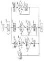
図3に示すように、パワーパック内の回路はパワーヘッド40およびコンソール30の作動を制御する中央処理ユニット(CPU)52を含む。このCPUは、アリゾナ州85284、テンペ、2110イーストエリオットのモトローラ社により製造されている、MC68332FNマイクロプロセッサのようなプログラマブルマイクロプロセッサであることが好ましい。このマイクロプロセッサは68000ファミリーのマイクロプロセッサの一つである。マルチタスクサポートを特徴とし、本明細書に記載されている回路のようないわゆる「エンベッド」環境で使用するように設計されているので、通常の数より多い数のダイレクトワイヤ式入出力ポートを有する。 As shown in FIG. 3, the circuitry in the power pack includes a central processing unit (CPU) 52 that controls the operation of the
このCPUは多数のメモリおよび通信用部品、更にこれら部品との間でデータを検索し、および/または送信するためのデータバス56をアドレス指定するためのアドレスバス54に接続されている。バッファ55および57はCPU52をアドレスバスおよびデータバスとそれぞれインターフェースするのに補助する。以下、アドレスバスおよびデータバスに接続された素子の各々について簡単に説明する。 The CPU is connected to a number of memory and communication components and to an address bus 54 for addressing a data bus 56 for retrieving and / or transmitting data to and from these components. Buffers 55 and 57 assist in interfacing CPU 52 with the address and data buses, respectively. Hereinafter, each of the elements connected to the address bus and the data bus will be briefly described.
データバス56に接続された消去可能なプログラマブルリードオンリーメモリ(EPROM)58は、CPU52を作動させるプログラムソフトウェアを含んでいる。このEPROMはCPUの低レベル管理、CPUと他の回路との通信および注射シーケンスを実行するようコンソールおよびパワーヘッドを制御するためのカスタムプログラムを実行するオペレーティングシステムを含む。ある実施例では、このオペレーティングシステムソフトウェアは、オレゴン州97229、ポートランド、サイエンスパークドライブ14215、N.W.のUSソフトウェア社により販売されている6800シリーズのマイクロプロセッサ用マルチタスクオペレーティングシステムであるUSX68Kオペレーティングシステムであり、カスタムプログラムはCプログラム言語で書かれている。このカスタムプログラムについては後に説明する。 An erasable programmable read only memory (EPROM) 58 connected to the data bus 56 includes program software for operating the CPU 52. The EPROM includes a low-level management of the CPU, communication between the CPU and other circuitry, and an operating system that executes a custom program to control the console and powerhead to perform the injection sequence. In one embodiment, the operating system software is available from Science Park Drive 14215, N.D., 97229, Portland, Oregon. W. USX68K operating system, a multitasking operating system for 6800 series microprocessors sold by US Software Company, Inc., with custom programs written in the C programming language. This custom program will be described later.
データバス56に接続された第2EPROM60は、ディスプレイ32(図2A)上に表示するためのディスプレイを発生する際に、EPROM56内のプログラムソフトウェアにより使用される言語情報を含む。ディスプレイ32上に示されるディスプレイスクリーンは、注射器の行う動作のテキスト記述およびオペレータが選択できるメニュー選択を含む。これらディスプレイ要素のテキスト部分は、言語用EPROM56に記憶されており、これらテキスト部分はこのEPROMから検索され、CPU52がディスプレイスクリーンを発生している際のテンプレートに挿入される。この言語用EPROMは、コンソールのキーボード34で入力したメニュー選択により、オペレータがスクリーンディスプレイを発生する好ましい言語を選択できるように、異なる言語を示す各テキストインサートの多数の変形例を含む。北米およびヨーロッパのマーケット用に適した言語のセット例としては、英語、ドイツ語、フランス語およびスペイン語となる。 A second EPROM 60 connected to the data bus 56 contains language information used by the program software in the EPROM 56 when generating a display for display on the display 32 (FIG. 2A). The display screen shown on display 32 includes a text description of the operation to be performed by the syringe and menu choices that can be selected by the operator. The text portions of these display elements are stored in the language EPROM 56, which text portions are retrieved from the EPROM and inserted into the template when the CPU 52 is generating the display screen. The language EPROM includes a number of variations of each text insert indicating a different language so that the menu selection entered on the
データバスには第3の電気的に消去可能なプログラマブルリードオンリーメモリ(EEPROM)62が取り付けられている。このEEPROM62は、不揮発状(電源がオフになってもデータが失われないように)データを記憶しており、特にプリプログラムされた注射シーケンスを記憶している。これらシーケンスはユーザーが望むように作成し記憶される(詳細については後に図6を参照して説明する)。更にEEPROM62は注射実行中に受ける流体圧力およびプランジャー位置情報を解釈するのにCPU52が使用するキャリブレート情報を記憶している。更にこのEEROM62は最も最近に完了した注射についての情報、例えば注射時間および注射容量を記憶しているので、オペレータがこの情報を検索できるようになっている。EEROM62は更に、オペレータがコンソールに入力したオペレータの優先データも記憶している(下記の図10を参照)。この優先データとしては、好ましいディスプレイ言語、時間および日付フォーマットがある。更に、EEROM62は作動パラメータ例えばプログラム可能な圧力限界および注射装置を図1Bに示したタイプの部分的にあらかじめ充填した注射器と共に使用するかどうかを示すフラグ(これは下記に示すように使用される)を記憶している。最後にこのEEROM62は、サービスおよびオンラインによるカスタマーサポートを容易とするよう、装置の所有者の登録名および/または番号を記憶している。 A third electrically erasable programmable read only memory (EEPROM) 62 is attached to the data bus. The EEPROM 62 stores non-volatile data (so that data is not lost even when the power is turned off), and particularly stores a preprogrammed injection sequence. These sequences are created and stored as desired by the user (details will be described later with reference to FIG. 6). Further, EEPROM 62 stores calibration information used by CPU 52 to interpret fluid pressure and plunger position information received during the execution of the injection. Further, the EEPROM 62 stores information about the most recently completed injection, such as injection time and injection volume, so that the operator can retrieve this information. The EEROM 62 further stores operator priority data input to the console by the operator (see FIG. 10 below). This priority data includes the preferred display language, time and date format. In addition, EEPROM 62 may include operating parameters such as programmable pressure limits and a flag indicating whether the injection device is to be used with a partially pre-filled syringe of the type shown in FIG. 1B (this is used as described below). I remember. Finally, this EEPROM 62 stores the registered name and / or number of the device owner to facilitate service and online customer support.
データバス56はランダムアクセスメモリ(RAM)64にも接続されており、このメモリはCPU作動中に発生されるレジスタの値のスタック、およびCPU上で走る現在作動していないプロセスに対応するマシンステート情報を記憶するように、オペレーティングシステムにより使用される。アプリケーションソフトウェアは(オペレーティングシステムにより管理され、割り当てられるような〜RAM64内の残りのスペースを使用し、注射装置の作動中に計算され、かつ操作される変数を記憶する。 The data bus 56 is also connected to a random access memory (RAM) 64, which stores a stack of register values generated during CPU operation and machine states corresponding to currently inactive processes running on the CPU. Used by the operating system to store information. The application software uses the remaining space in RAM 64 (as managed and allocated by the operating system) and stores variables calculated and manipulated during operation of the injection device.
CPU52とパワーヘッド42とコンソール30との間の通信信号のほとんどは、データバスに接続されている2つのユニバーサル非同期受信/送信機(UART)66、68の一方を通して送られる。UARTは一般に集積回路として入手可能な通信用回路であり、出入力情報を収集し、かつバッファ化し、データリンクを通るプロセッサ間または計算システム間の非同期通信を可能にするものである。モトローラ社から販売されているMC68681がこのUARTに適している。第1UART66は、インターフェース70およびパワーヘッドに接続されている通信ケーブル71を通るパワーヘッド回路(図5の下方参照)との通信を行う役割を果たす。(しかしながらパワーヘッド上の光エンコーダ166からのパルスはインターフェース70からライン71を通ってCPU52上のインターラプト入力端に進む。)UART60は補助インターフェース72との通信も処理する。この補助インターフェースは通信ケーブル73を介してプリンタに結合でき、CPU52が注射の記録をプリントできるようにしている。これとは異なり、インターフェース72(または同様のインターフェース)を用いて、CPU52を遠隔地のコンピュータまたは他の外部デバイスに取り付け、注射装置の遠隔モニタリングおよび/または制御を可能にできる。 Most of the communication signals between the CPU 52, the powerhead 42 and the
第2UART68は、コンソール30(図2A)との通信の役割を分担している。ケーブル75、76を介してパワーパックに2つのコンソール30を接続できる。
ケーブル75および76はパワーパック50とコンソール30との間でキーストロークおよびスクリーン動作を表示するデータを搬送する。このデータは通信シーケンスでエンコードされており、RS422規格に従って送信される。このエンコードされたデータはライン75および76を介してインターフェース74へ送られ、インターフェース74は第2UART68のための送信信号をエンコードし、かつデコードする。UART68はいずれかのコンソールによりインターフェース74を介してCPU52に受信されたキーストロークをデータバス56を介してルート決定し、更にCPU52によりインターフェース74に発生されたディスプレイ情報をルート決定し、ライン75Aおよび76Aを介してコンソールへ送信する。The second UART 68 has a role of communicating with the console 30 (FIG. 2A). Two
ケーブル75および76は別個の導線上にライン75Bおよび76Bも含み、これらラインは各コンソールキーボードのキー38(図2A)に対応する論理信号を搬送する。下記に詳述するように、コンソールディスプレイを駆動するソフトウェアはキー38が最も頻繁に使用されるキーとなるように書かれている。このキー38は、ディスプレイ中のスクリーンに応じ、スクリーンを出る「Exit」キー、値または選択を受け入れスクリーンを出る「Enter」キーまたは操作を終了する「Disable」または「Cancel」キーとして機能する。(図6〜11を参照してスクリーンの例について説明する。)キー38は最も多く使用されるキーであり、キャンセルコマンドのような時間応答入力信号用に使用されているので、このキー38は他のキーとは異なり、CPU50に接続されている。このキーは割り込みライン79を介してCPU52に直接接続されている。キーストロークが検出されると、マスク不能な割り込みインターフェース(NMI)78(これはライン75Bおよび76B上の信号をライン79上のクリーンな論理信号に変換するRS422送受信機を構成する)はライン79上に割り込み信号をセットする。この割り込み信号はすぐに検出され、その後CPU52で処理される。
リモートハンドスイッチ用に同様なインターフェースが使用されている。ハンドスイッチから延びるケーブル81は、ハンドスイッチインターフェース回路80に接続しており、このインターフェース回路80は特に、パワーパックのアースからのハンドスイッチを電気的に絶縁し、ハンドスイッチボタンが押されているか、または離されているかどうかを表示するクリーンな論理信号を発生するよう、ハンドスイッチからのノイズ(このノイズはスイッチを押したり離したりする時に生じる)を除く。この論理信号はライン82を介しCPU52上の時間処理ユニット(TPU)ポートに送られる。CPU52は、このTPUポートにおける論理信号を読み取り、EPROM58内のソフトウェアに従って適宜応答する。 A similar interface is used for remote hand switches. The cable 81 extending from the handswitch connects to a handswitch interface circuit 80, which in particular electrically isolates the handswitch from the power pack ground and whether the handswitch button is pressed, Or remove the noise from the hand switch (which occurs when pressing and releasing the switch) to generate a clean logic signal indicating whether or not the switch has been released. This logic signal is sent via line 82 to a time processing unit (TPU) port on CPU 52. The CPU 52 reads the logic signal at the TPU port and responds appropriately according to the software in the
CPUデータバス56上の最終コンポーネントは、アナログ/デジタルコンバータ(A/D)84である。このコンバータはライン85上で受信されるアナログ信号に対応するデータバス56から読み出されるデジタル信号を発生するのに使用される。このA/Dコンバータとしては、カリフォルニア州95035、ミルピタス、1630マッカーシー・ブルバードのリニアテクノロジー社によって販売されている、LT1094が適当である。A/Dコンバータ84は、下記のモータサーボ制御回路によって使用される。CPUはモータサーボ制御回路にたいする2つの付加的インターフェースを有する。すなわちデジタル/アナログコンバータ(D/A)86に対するライン87上のインターフェース(これはライン87上で受信されたデジタル信号に対応するアナログ信号をライン88上に発生し、例えばマサチューセッツ州02062、ノーウッド私書箱9106のアナログデバイセス・オブ・ワンテクノロジーウェイから販売されているAD7245である)と、圧力限界制御回路92に対するライン90上に第2インターフェースを有する。これらインターフェース(ライン87および90)は、マイクロプロセッサ上の同期周辺インターフェース(SPI)チャンネルに接続しており、EPROM58内のソフトウェアに従って制御される。 The final component on the CPU data bus 56 is an analog / digital converter (A / D) 84. This converter is used to generate a digital signal that is read from data bus 56 corresponding to the analog signal received on line 85. A suitable A / D converter is the LT1094 sold by Linear Technology of 1630 McCarthy Boulevard, Milpitas, 95035, California. The A / D converter 84 is used by the following motor servo control circuit. The CPU has two additional interfaces to the motor servo control circuit. That is, an interface on line 87 to a digital-to-analog converter (D / A) 86 (which generates an analog signal on line 88 that corresponds to the digital signal received on line 87, for example, Norwood PO Box 9106, Norway 02062, Mass.) And a second interface on line 90 to a pressure limit control circuit 92. The AD7245 is available from Analog Devices of One Technology Way, Inc. These interfaces (lines 87 and 90) connect to a synchronous peripheral interface (SPI) channel on the microprocessor and are controlled according to software in
D/A86、A/D84、サーボ制御回路94、圧力限界制御回路92および圧力検出回路96は、集合してモータサーボ制御回路を形成しており、この回路は注射器のプランジャーを注射器の内外へ駆動するモータ98の作動を制御する。(明瞭化のためモータ98が示されているが、このモータ98は物理的にはパワーヘッド40の中に設けられていると解すべきであり(図2B、図5)、ライン92および93はパワーヘッド40およびパワーパックに接続するコンピュータインターフェースケーブルの数本の導線を介してモータに接続している。) The D / A 86, A / D 84, servo control circuit 94, pressure limit control circuit 92, and
サーボ制御回路94はD/A86によりライン88上に発生されたアナログ電圧に応答し、ライン99と100との間に対応する電圧を発生する。ライン99および100上の電圧は、ライン91および93を解してモータ98を駆動するのに十分なレベルまでトランス102により変換される。サーボ制御回路94は、スイッチング用FETのデューティサイクルに関連した出力電圧を発生するフライバックトランス回路を含む。このデューティサイクルは、集積回路であるUC3525パルス幅変調(PWM)回路により発生され、このPWM回路はライン88上のアナログ入力電圧に応答して、デューティサイクルが0%〜50%変化する100kHzのデジタル出力信号を発生する。このPWM回路としては、ニューハンプシャー州03054、メリマック、7 コンチネンタル・ブルバードのユニトロード社により販売されているUC3525が適当である。従って、CPU52は、ライン87を介しD/A86に所望の出力電圧を表示するデジタルワードを書き込むことにより、モータ98の速度およびパワー出力を制御する。このデジタルワードは次にアナログ信号に変換され、このアナログ信号はサーボ制御回路内でパルス幅変調制御信号に変換される結果、モータでは所望の出力電圧が得られる。 Servo control circuit 94 is responsive to the analog voltage generated on line 88 by D / A 86 to generate a corresponding voltage between
圧力検出回路96は電流検出回路を含み、この回路はライン93を通る電流(すなわちモータを通る電流)を検出し、検出された電流に比例するアナログ信号をライン104および85上に発生する。本質的にはこの電流検出回路は、モータ98に取り付けられたライン93と直列なハイパワー定格の小抵抗器から成る。(低ノイズのハイコモンモードリジェクションのオペアンプに基づく)電圧差動アンプは、抵抗器の両端の電圧を検出し、この電圧をライン85および104上のアナログ電圧に変換する。モータを流れる電流は、モータが発生する力、すなわち注射圧力に比例している。従って、圧力検出回路96により発生されるアナログ信号を用いて、注射圧力を求めることができる。
圧力限界制御回路92は、ライン104上のアナログ信号を用いてハードウェア圧力制御関数を演算する。この圧力限界制御回路92は、アナログ比較電圧を発生するのに使用される市販デジタルポテンショメータを含む。このポテンショメータとしては、テキサス州75244、ダラス、4350 ベルトウッドパークウェイ・サウスのダラスセミコンダクター社によって販売されている、DS1267が適する。CPU52は、(ライン90を介して)このポテンショメータのプログラムを実行し、最大許容圧力に対応する比較電圧を発生する。圧力限界制御回路92は、比較電圧と圧力検出回路96により発生されたライン104上のアナログ信号とを比較するコンパレータを含む。この圧力が最大許容圧力を越えると(これはCPU52の故障を示す)、ライン105上にてサーボ制御回路94にデジタル信号が送信され、このサーボ制御回路94はこれに応答してライン88上のアナログ信号を無視し、その代わりにライン99および100上の電圧を低下してモータを停止する。従って、CPU52が圧力限界制御回路92に正しい最大圧力のプログラムを組むと、注射装置はCPU52が故障したとしてもその圧力を越えることはない。 The pressure limit control circuit 92 computes a hardware pressure control function using the analog signal on
正常な条件下では、CPU52は、モータの性能および発生圧力に対し連続的にフィードバックをかけ、D/A86によりモータを制御して、所望の注射シーケンスを得るので、このハードウェアの圧力限界に達することはない。CPU52は3つのソースから進行中の注射にフィードバックをかけている。すなわち、(1)圧力検出回路96により発生されるライン85上のアナログ電圧に対応するデジタルワードをバス56に発生するA/D84から注射圧力に対するフィードバックをかけており、(2)(図5を参照して下記に詳述するように)パワーヘッド40の内部のモータに物理的に結合された光エンコーダ166から、モータの速度にフィードバックをかけており、(3)(図5参照)プランジャーに物理的に結合されたリニアポテンショメータ168から、注射器の内部のプランジャー位置にフィードバックをかけている。この情報を用い、CPU52はEPROM58内のソフトウェアの制御によりあらかじめプログラムされたシーケンスに従って注射圧力、容積および速度を注意深く制御する。 Under normal conditions, the CPU 52 provides continuous feedback on motor performance and generated pressure and controls the motor with the D / A 86 to obtain the desired injection sequence, thus reaching the hardware pressure limit. Never. CPU 52 provides feedback on ongoing injections from three sources. That is, (1) the digital word corresponding to the analog voltage on the line 85 generated by the
パワーパック、パワーヘッドおよびコンソールディスプレイのための電力は、ACパワーライン107および108により供給される。ACライン電圧は米国以外の国のライン電圧にも使用できるよう、調節可能なトランスと、検出されたライン電圧に基づく適当なトランスを選択するための電圧検出回路とを含む、従来の電源回路106によって変換されている。電源は注射装置を抜くか、好ましくはリモートオンオフ回路110内の固体リレーを開閉するトグルスイッチにより切ることができる。 Power for the power pack, power head and console display is provided by
図4を参照すると、コンソール回路は汎用CPU120の回りにも設けられている。このマイクロプロセッサにはMC68332FMが適当である。アドレスバス122およびCPU120に接続されたデータバス124は多数の支持回路に接続している。プログラムROM126は、CPU120を管理するソフトウェアを含む。(このソフトウェアはアセンブリ言語で書かれている。)フォントROM128は、ディスプレイスクリーン上に発生されるテキスト用フォントを発生する際に、CPU120により検索されるフォント情報を含む。これらフォントは外国言語テキストをサポートすることが必要な場合、外国語のキャラクター(文字)を含む。RAM130は、ディスプレイおよび検索操作を実行する際に、マイクロプロセッサにより使用される。バッテリーでバックアップされたRAM132は、1日のうちの現在の時刻を記録しているので、パワーパックは注射の日付および時間のスタンプされた記録を作成できる。 Referring to FIG. 4, the console circuit is also provided around the general-
コンソール回路の使用機能はディスプレイ32上にスクリーンを発生し、かつ、8個のキーのキーパッド34(図2A)からのキーストロークを受信し、キーストロークをパワーパックに中継することである。ディスプレイはディスプレイコントローラ134、例えばカリフォルニア州、95134、サンホセ、3050、ザンカーロードのチップス・アンド・テクノロジー社により販売されているF82C455VGAコントローラによって発生される。このVGAコントローラはアドレスバッファ136およびデータバッファ138を介してCPU120と相互作用し、ダイナミックランダムアクセスメモリ(DRAM)140内にスクリーン情報を記憶する。ライン142を介してディスプレイ32に情報が送られる。 The use function of the console circuit is to generate a screen on the display 32 and to receive keystrokes from the eight-key keypad 34 (FIG. 2A) and relay the keystrokes to the power pack. The display is generated by a display controller 134, such as the F82C455 VGA controller sold by Chips and Technology, Inc., 3050, San Jose, San Jose, 95134, California. The VGA controller interacts with
キーパッドからのキーストロークはキーボードインターフェース回路144により受信される。この回路はキーストロークのチャッタリングを防止し、ライン146上にクリーンな論理信号を発生する。これらの論理信号はCPU120にフィードバックされるので、CPUはスピーカー制御回路150を介して可聴トーンを発生することにより、キーストロークを確認できる。スピーカー制御回路は、ユニークな音響信号も発生し、他の作動、例えば注射の開始を表示したり、スキャンニングを開始すべきことをオペレータに知らせることもできる。このコントローラとしては、モトローラ社により販売されているMC3487が適当である。CPU120は、ライン75および76を通してデジタル信号を送受信するRS422インターフェース回路148を介し、パワーパックと通信する。インターフェース回路148は、キーボードインターフェース144からのキーストロークを直接送受信することも行う。コンソール上の8つのキーは、一つで8ビットバイトの情報(ここで書くビットはキーが押されているか離されているかを表示する)を発生する。このバイトは245タイプの論理バッファを介してCPU120に直接送られる。 Keystrokes from the keypad are received by the keyboard interface circuit 144. This circuit prevents chattering of keystrokes and generates a clean logic signal on line 146. Since these logic signals are fed back to the
+28ボルトのDCパワーは、ライン152を介しパワーパック内の電源から発生される。電源回路154は、この+28ボルトのDC電力ラインをコンソール内の種々の回路が必要とする一組の電源電圧に安定化する。更に、電力インバータ回路は電源回路154により発生される+12ボルトのDC電力を液晶ディスプレイを附勢するための低電流の600ボルトのAC電力に変換する。 +28 volts DC power is generated from the power supply in the power pack via
図5を参照すると、パワーヘッドはパワーパック50(図2C)との通信を行うためのマイクロプロセッサを含む回路ボード160も有する。このマイクロプロセッサとしては、68000ファミリーの低コストの最小機能のマイクロプロセッサである、モトローラ社で販売されている68HC11E2がある。回路ボードは(上記)キーボード162上のボタンからのキーストロークおよびパワーヘッドの背部に取り付けられた手動ノブ163からの運動を表示する電気パルスを送受信する。この手動ノブとしては、ニューハンプシャー州03820、ドーバー、1ワシントンストリートのコラロスタッド社により販売されているモデル600サムホイールが適当である。この回路ボード(基板)は注射/故障インディケータライト49Aおよびイネーブルされたイネーブルライト49Bを点灯および消灯する。 Referring to FIG. 5, the powerhead also has a circuit board 160 that includes a microprocessor for communicating with the power pack 50 (FIG. 2C). This microprocessor is the 68HC11E2 sold by Motorola, a low cost, minimal function microprocessor of the 68000 family. The circuit board sends and receives electrical pulses indicating keystrokes from buttons on the keyboard 162 (described above) and movement from a
モータ98はモータの回転運動をプランジャーの線形並進運動に変換するギアボックスに結合されている。このモータとしては、イリノイ州61125、ロックフォード、私書箱7040、バーバーコールマン社によって販売されている、CYMS A2774−2モータが適当である。モータの回転は光エンコーダ166により検出される。(このエンコーダ166は光源と光検出器との間で回転するピンホイールを含み、例えばカリフォルニア州95054、3003スコットブルバードのヒューレットパッカード社により販売されている、HEDS−9100エンコーダで構成される。)このエンコーダ166は、回路ボード160に電気パルスを送り、回路ボードはこれら電気パルスをパワーパック50にリレーし、パワーパック内のCPU52がモータの運動をモニタできるようにしている。 Motor 98 is coupled to a gearbox that converts the rotational movement of the motor into a linear translation of the plunger. A suitable motor is the CYMS A2774-2 motor sold by Barber Coleman, Inc., PO Box 7040, Rockford, Illinois 61125. The rotation of the motor is detected by the
プランジャーの位置は、リニアポテンショメータ168により検出され、このポテンショメータは例えばカリフォルニア州92054、オーシャンサイド、215ビアデルモルテのETIシステムズ社により販売されているLCPL200である。ポテンショメータ168の摺動子169は、プランジャー12に機械的に結合されており、このプランジャー12と共に移動する。ポテンショメータのターミナル170と171との間でDC電圧が低下し、この結果、プランジャーおよび摺動子169の位置を示すアナログ電圧が摺動子169に発生する。回路ボード169内のADコンバータはこのアナログ信号をデジタル信号に変換し、回路ボード160はこのデジタル信号をパワーパック50に送る。 The position of the plunger is detected by a
回路ボード160は2つのホール効果センサ172および174の出力も検出する。パワーヘッドは取り外し自在なフェースプレート42(図2B)を有し、異なる大きさの注射器を嵌合するための異なる寸法の孔を有する、異なるフェースプレートが、現在のところ2つ設けられている。従って、注射器を交換するには、フェースプレートを取り外す必要はないが、異なる大きさの注射器を用いる場合、取り外すことができる。センサ172は、フェースプレート42が開いているかどうかを検出し、開いている場合、回路ボード160はフェースプレートが閉じるまで更なる注射手順を防止するメッセージをパワーパック50に送る。センサ174は使用中のフェースプレートの大きさを検出する。現在のところ、2つのフェースプレートのうちの一方しか、センサ174のトリガーを引くマグネットを含んでいないので、回路ボードはセンサ174がトリガーされたかどうかを判別することにより、いずれのフェースプレートが取り付けられているかを判断できる。この情報も、パワーパック内のCPU52に送られるので、CPU52は(下記のように)モータ98を制御する際、注射器の異なる寸法を補償できる。 Circuit board 160 also detects the outputs of two
回路ボード160はCPU52の指示でヒーターブラケット176を制御し、このブラケットは注射器内のコントラスト流体を加熱する。更に回路ボード160は、移動インディケータボード178を制御する。移動インディケータボード178は、プランジャー12に機械的に結合されており、パワーヘッド上のウィンドー44を介して見ることができる2つの発光ダイオードLED179を含む。LED179はダイオードの位置とウィンドー41上のメモリとを関連させることにより、オペレータにプランジャーの位置をフィードバックさせる。ウィンドー41の2つの辺は、異なる目盛りを含み、一方の目盛りは大きな注射器用に較正され、他方は小さい注射器用に較正されている。センサ174により検出された注射器の寸法に応じ、適当な目盛りの横のLEDが照明される。更に後に詳述するように、プランジャーが移動すると、CPU52は回路ボード160がLEDを点灯するように指示する。更にCPU52が上記のロックモードとなると、CPU52は回路ボード160がLEDを常時点灯するように指示する。従って、LED179はプランジャーの位置、移動方向およびロックモードについてオペレータにフィードバックする。 The circuit board 160 controls the
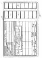
図6〜11を参照し、オペレータの立場から注射シーケンスについて説明する。図6に主要作動スクリーンが示されている。パワーヘッドのアイコン表示201に関連するボックス200は、注射器内のコントラスト媒体の現在の容積を識別し、注射器のアイコン表示203に関連するボックス202は、現在選択されているシーケンス中において繰り出された総容積を識別する。ボックス204は、オペレータによりあらかじめ選択された圧力限界を識別し、ボックス206は、オペレータが注射を開始(ハンドスイッチ、コンソール上のキーまたはパワーヘッド上のボタンのいずれかによる)した時刻から、被検体のX線または磁気スキャンを開始するまでの遅延時間である操作遅延(秒)を識別する。(この遅延の終了時にはCPU120はスキャンを開始すべきであること、またはスキャナーと注射装置との適当な電気接続によりスキャンを自動的に開始できることをオペレータに知らせるトーンを発生する。)図示された状態では、注射器は180mlの流体を含み、そのうちの300mlが現在選択されているシーケンスにより使用され、圧力限界は200psiであり、スキャン遅延はない状態になっている。 The injection sequence will be described from an operator's standpoint with reference to FIGS. FIG. 6 shows the main operating screen. The
図6に示すディスプレイでは、スクリーンディスプレイの上部領域には注射シーケンスが記憶されている。領域208はオペレータが選択できるシーケンスを識別し、表示しており、領域210は現在選択されているシーケンスの細部を示している。領域210に示すように、シーケンスは多くのフェーズから成る。各フェーズの間で注射装置はあらかじめプログラムされた流量を発生し、あらかじめプログラムされた総流体容積を出力する。図示されたシーケンス「SERIO VASCUL」は一つのフェーズしか有していないが、オペレータが選択できる他のシーケンスは多数のフェーズを有する。領域201ではシーケンスは名称およびフェーズの番号によって識別されるので、「LIVER(肝臓)」シーケンスは2つのフェーズを有し、「ABDOMEN(腹部) PI」シーケンスは3つのフェーズを有する。 In the display shown in FIG. 6, the injection sequence is stored in the upper area of the screen display.
ユーザーはシーケンスを選択し、注射を可能とできるが、それ以外にはディスプレイの横のキーパッド34上のボタンを押すことにより、ディスプレイスクリーンを通してナビゲートできる。ディスプレイの領域212はキーパッド34上のボタンから利用可能な機能を識別する専用のものとなっている。従って図6に示されるこのディスプレイでは、ユーザーはディスプレイ上のワード「PREVIOUS PROTOCOL(先のシーケンス)」および「NEXT PROTOCOL(次のシーケンス)」のボタンを押すことにより、領域208内のリスト内の先のまたは次のシーケンスをそれぞれ選択することができる。また、ユーザーは「CHANGE VALUES(値変更)」のボタンを押すことにより、現在のシーケンスの流量、容積および注射遅延値を変更し、これを記憶することもできる。このようにすることにより、キーパッドの機能およびディスプレイの領域212が変わるので、オペレータは値を選択し、値を増減し、文字を選択し、シーケンス名を編集し、図6に示されるディスプレイにリターンできる。図6から、オペレータは操作パラメータおよびその他データを調節するように、制御パネルディスプレイ(図10、下記参照)を入力できる。また、オペレータはシーケンスの名称変更または削除を行うシーケンスマネージャーを入力でき、領域208に示されているシーケンスリストの順を決定できる。最後に、ユーザーは「ENABLE(可能)」ボタンを押すことにより、図6に示されているディスプレイから注射を可能にできる。 The user can select a sequence and enable an injection, but otherwise navigate through the display screen by pressing a button on the
図7に示すように、ユーザーが注射を可能にすると、安全対策として注射装置はまず注射器から空気のすべてが排気されたかどうかをオペレータに質問するテキストボックス214を表示する。このディスプレイの領域212は、ワード「YES」および「NO」しか含んでいない。このことは、オペレータはyesまたはnoのいずれかで質問に答えなければならないことを意味している。「NO」ボタンが押されると、注射はキャンセルされる。答えが「YES」であれば注射装置は図8に示すような可能状態に進む。ここでディスプレイの領域208は予想期間を示し、領域212はワード「START」、「AUTO ENABLE」および「EXIT」を含む。オペレータが「EXIT」ボタンを押すと、注射装置は図6に示される状態に復帰する。オペレータが「AUTO ENABLE」ボタンを押すと、注射装置はスクリーンの中心部の簡単表示ボックスにより確認されるオートイネーブルモードに入ったり、これより出たりする。オペレータが「START」ボタンを押すと、注射が開始し、注射装置が図9に示される状態に移動する。 As shown in FIG. 7, when the user enables injection, as a safety measure, the injection device first displays a text box 214 asking the operator whether all of the air has been exhausted from the syringe.
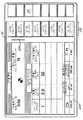
注射が進行している間は、図9に示されるディスプレイが表示される。このディスプレイでは領域208は総注射時間および被検体に注射される容積(ml)を示す。領域212のキーパッド34上のボタンの各々にはワード「STOP」が示されているが、これはボタンのいずれかを押すことにより(またはパワーヘッド上のスタート/ストップボタン45またはハンドスイッチを押すことにより)、オペレータが注射を中止できる。 While the injection is in progress, the display shown in FIG. 9 is displayed. In this display, the
注射シーケンスが完了した後に、注射装置は図6に示される状態または図8に示される状態のいずれかに復帰する。図8の「AUTO ENABLE」を押して注射装置をオートイネーブルモードにすると、注射装置は図8に示される状態に復帰する。しかしながらオペレータが注射装置をオートイネーブルモードにしないと、注射装置は図6に示される状態に復帰する。従って注射装置をオートイネーブルモードにすることによりオペレータはより容易に注射シーケンスを繰り返すことができる。このモードは例えばコントラスト媒体が比較的急速に拡散し、被検体の同一領域について多数の像を撮影する場合に有効である。この「AUTO ENABLE」ボタンを用いることにより、注射装置を再イネーブル化することなく、一つのキーまたはハンドスイッチを押すことにより、各像の直前にコントラスト媒体を補充できる。 After the injection sequence is completed, the injection device returns to either the state shown in FIG. 6 or the state shown in FIG. Pressing "AUTO ENABLE" in FIG. 8 to place the injection device in the auto-enable mode returns the injection device to the state shown in FIG. However, if the operator does not put the injector in the auto-enable mode, the injector returns to the state shown in FIG. Therefore, by setting the injection device to the auto enable mode, the operator can more easily repeat the injection sequence. This mode is effective, for example, when the contrast medium diffuses relatively quickly and a large number of images are taken of the same region of the subject. By using this "AUTO ENABLE" button, the contrast medium can be replenished just before each image by pressing one key or hand switch without re-enabling the injection device.
上記のように、注射オペレータは注射のためにあらかじめ充填された注射器を用いたいと考える場合がある。しかしながらあらかじめ充填された注射器は注射器の充填容積を減少するイクステンダーを含んでいることが多い。(このタイプの注射器は部分的にあらかじめ充填された注射器として知られている。)本明細書に記載の注射器は下記の部分的にあらかじめ充填された注射器の小容積を補償するという特徴を有している。 As noted above, an injection operator may wish to use a pre-filled syringe for injection. However, pre-filled syringes often include an extender that reduces the fill volume of the syringe. (This type of syringe is known as a partially pre-filled syringe.) The syringes described herein have the feature of compensating for the small volume of the following partially pre-filled syringes: ing.
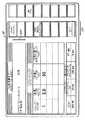
上記のように注射装置をセットアップするにはオペレータは図10に示される「Control Panel」に入力すればよい。この制御パネルではディスプレイは、注射装置の現在の操作セッティングを識別する。従って制御パネルは現在の圧力限界を示すボックス220と、現在の言語(上記のようにオペレータはディスプレイのテキスト部分のための言語を選択できる)を示すボックス222と、現在の時間および日付を示すボックス226および228、および所有者の登録名および/または番号を示すボックス230を含む。この情報は、上記のようにキーパッドおよびディスプレイの領域212を用いて入力される。 To set up the injection device as described above, the operator may enter the "Control Panel" shown in FIG. In this control panel, the display identifies the current operating setting of the injection device. Thus, the control panel displays a
「Control Panel」の別ボックス232は、部分的にあらかじめ充填された注射装置と共に用いるかどうかを示すのに使用される。ボックス232にはオペレータが選択するワード「YES」または「NO」を含む。(図10に示すように、ユーザーがこのボックスを変えたい場合、ディスプレイの領域212はメニューに「YES」または「NO」の選択を与える。) Another box 232 of "Control Panel" is used to indicate whether to use with a partially pre-filled injection device. Box 232 contains the word "YES" or "NO" selected by the operator. (As shown in FIG. 10, if the user wants to change this box,
オペレータが部分的にあらかじめ充填された注射器を用いることができることを表示するよう、ボックス232を変える場合(すなわちボックス232はYESの表示をする)、上記イネーブル手順を若干変える。オペレータが図6のディスプレイの「ENABLE」ボタンを押すことにより、注射を可能にした後、部分的にあらかじめ充填された注射器を用いることができるようにした場合、注射装置は図11に示すスクリーンを表示し、ここでオペレータは50ml、65ml、75ml、100mlまたは125mlのボタンを押すことにより、あらかじめ充填された注射器の寸法を表示しなければならない。オペレータが一旦入力した充填された注射器の寸法を表示すると、注射装置は図7に示すディスプレイとなる。CPU52(図3)は、次に、図13を参照して下記に説明するように、注射器内のイクステンダーを補償する。 If box 232 is changed to indicate that the operator can use a partially pre-filled syringe (ie, box 232 displays YES), the enable procedure is slightly changed. If the operator enabled the injection by pressing the “ENABLE” button on the display of FIG. 6 and then enabled the use of a partially pre-filled syringe, the injection device would display the screen shown in FIG. Display, where the operator must display the dimensions of the pre-filled syringe by pressing a 50 ml, 65 ml, 75 ml, 100 ml or 125 ml button. Once the dimensions of the filled syringe have been displayed by the operator, the injection device becomes the display shown in FIG. CPU 52 (FIG. 3) then compensates for the extender in the syringe, as described below with reference to FIG.
図12を参照すると、パワーをオンにすると、CPU52内で作動するプログラムが開始する(240)。プログラムはまず、パワーパック50、パワーヘッド40およびディスプレイ内のハードウェアおよびソフトウェアを初期化し(242)、次にCPU52は注射装置が正しく作動するように診断を実行(244)する。この場合、種々のハードウェア要素にテストデータを送り、正しい応答が受信されたかどうか検証を行う。 Referring to FIG. 12, when the power is turned on, a program operating in the CPU 52 starts (240). The program first initializes (242) the hardware and software in the
これら診断が合格した後、CPU52は多数の「スレッド」すなわち並列プロセスを開始し、その後これらプロセスは上記USX68Kで作動するシステムの制御によりCPU52上で時間多重化される。これらスレッドはメッセージすなわち信号によりオペレーティングシステムと通信し、かつ相互に通信し、オペレーティングシステムにより管理されているグローバルにアクセス可能なエリアに内部プロセス通信が置かれ、ここでは他のスレッドにより内部通信信号が検索できるようになっている。オペレーティングシステムはプロセス時間をスレッドに割り当てる。多くの時間の間スレッドは不作動状態である。すなわち、実行するペンディング状態の演算はない。スレッドは一般に不作動状態の場合、オペレーティングシステムが他のスレッドに処理時間を再割り当てできるように、この事実(オペレーティングシステムに対する復帰時間)をオペレーティングシステムに通知するように書かれている。 After passing these diagnostics, CPU 52 initiates a number of "threads" or parallel processes, which are then time multiplexed on CPU 52 under the control of a system running on the USX68K. These threads communicate with the operating system and communicate with each other by messages or signals, and internal process communication is placed in a globally accessible area managed by the operating system, where internal communication signals are placed by other threads. You can search. The operating system allocates process time to threads. For many hours the thread is inactive. That is, there is no calculation of the pending state to be executed. A thread is generally written to notify the operating system of this fact (return time to the operating system) when the thread is inactive, so that the operating system can reassign processing time to other threads.
オペレーティングシステムは優先的なラウンドロビン状にスレッドに処理時間を割り当てる。従って、オペレーティングシステムは各スレッドに一般的に順に処理時間を与える。アクティブ状態の低優先度のスレッドが最大量の処理時間よりも長い時間を使用する場合、オペレーティングシステムはこのスレッドに割り込み、その他の優先度の高いほうのスレッドに処理時間を使用する機会を与える。しかしながら優先度の高いスレッドが最大量の処理時間よりも長く使用するかどうかとは無関係に、低い方のスレッドに割り込まれることはない。正常な作動条件下ではほとんどのスレッドはアクティブでなく、処理時間に関しスレッド間で競合することはない。しかしながら競合が生じるような場合、このような優先システムにより最も重要なスレッドが必要に応じて割り込まれないような状態に維持される。しかしながら、(割り込みが許容できる場合)最高優先度のスレッド(サーボスレッド254)が作動システムに時間を戻しても、他のスレッドは最高優先度のスレッドがアクティブであった場合でも作動を続けることができる。 The operating system allocates processing time to threads in a priority round robin manner. Thus, the operating system generally gives each thread processing time in turn. If an active low priority thread uses more time than the maximum amount of processing time, the operating system interrupts this thread and gives other higher priority threads the opportunity to use the processing time. However, regardless of whether a higher priority thread uses longer than the maximum amount of processing time, the lower priority thread will not be interrupted. Under normal operating conditions, most threads are inactive and there is no competition between threads for processing time. However, in the event of contention, such a priority system keeps the most important threads from being interrupted as needed. However, if the highest priority thread (servo thread 254) returns time to the operating system (if interrupts are acceptable), other threads may continue to operate even if the highest priority thread was active. it can.
CPU52内で作動するスレッドは、一般に2つのカテゴリー、すなわちパワーパック50の内外に情報を送る通信スレッドと、パワーパックにより送受信される情報を発生または処理する作動スレッドとに分かれる。作動スレッドは2つある。すなわち、ステートマシンスレッド246とサーボスレッド254とがある。 The threads that operate within the CPU 52 generally fall into two categories: communication threads that send information into and out of the
ステートマシンスレッド246は図6〜10に示されるタイプのスクリーンディスプレイを発生するようにコンソール30に指示すると共に、ユーザーにより押されたボタンを処理する。スレッド246は各ステートがディスプレイスクリーンに対応しているステートマシンであり、オペレータの各キーストロークにより、ステート変換信号が発生される。プログラムEPROM58(図3)は、本質的にはステート変換ダイヤグラム、特定の識別ステート、そのステートに関連したディスプレイおよび他のステートへの変換を生じさせる各ステートに対応するキーストロークまたは他のアクティビティを決めている。
図13に示すように、イニシエートされるとスレッド246はメッセージ、例えばコンソールボタンが押されたことを示す通信スレッドからのメッセージまたは最新の注射動作を表示するようディスプレイを更新するべきかどうかを示すサーボスレッドからのメッセージを探す(270)。メッセージが全く受信されない場合、スレッドはオペレーティングシステムへタイムをリターンする(272)。しかしながらメッセージが受信されると、スレッドはプログラムEPROM58内のソフトウェアを使用して、受信されたキーストロークすなわちアクティビティに関連した新しいステートを識別し、これに移行する(274)。あるケース、例えばオペレータが無効ボタンを押した場合、新しいステートは旧ステートと同じになるが、他のケースでは新しいステートは異なるステートとなる場合もある。新しいステートが異なるステートである場合、ステートマシンスレッドは適当な通信ステートにメッセージを送り、新しいステートを表示するように、スクリーンを変える(276)。更にステートマシンスレッドは、例えばシーケンスをスタートするボタンをオペレータが押したことをサーボスレッドに通知するよう、サーボスレッドにメッセージを送ることができる(278)。これが完了すると、ステートマシンはオペレーティングシステムにリターンする(280)。 As shown in FIG. 13, when initiated, the
スタートメッセージがサーボスレッドに送られると、メッセージを送るスレッドは一つ以上のグローバル変数をイニシエートし、リクエストされた運動の種類を示す。8つのグローバル変数(オペレーティングシステムにより管理され、すべてのスレッドによりアクセス可能な変数)が4つのペアに組織されており、この目的のために使用される。変数の各ペアは、プランジャの希望する新しい位置およびその位置へ移動する際のプランジャの速度を識別する。4つの変数ペアにより4つのシーケンスフェーズを記述できるので、これら4つのシーケンスフェーズはサーボスレッドへの一つのメッセージで実行できる。従って、ステートマシンスレッドがサーボスレッドにメッセージを送る(278)と、サーボスレッドは選択されたシーケンスからの一つ以上の所望の終了位置および速度を計算し、グローバル変数に計算された値を入れる。 When the start message is sent to the servo thread, the message sending thread initiates one or more global variables to indicate the type of motion requested. Eight global variables (variables managed by the operating system and accessible by all threads) are organized into four pairs and are used for this purpose. Each pair of variables identifies the desired new position of the plunger and the speed of the plunger in moving to that position. Since four sequence phases can be described by four variable pairs, these four sequence phases can be executed by one message to the servo thread. Thus, when the state machine thread sends a message to the servo thread (278), the servo thread calculates one or more desired end positions and velocities from the selected sequence and populates the global variables with the calculated values.
図14を参照する。サーボスレッド254は、オペレーティングシステムによりイニシエートされると、プランジャの移動を開始するようサーボに送られるメッセージをまずチェックする(282)。メッセージが受信されない場合、サーボスレッドはオペレーティングシステムへタイムをリターンする(284)。しかしながら、スタートメッセージが受信されると、サーボスレッドはグローバル変数により示される所望位置へグローバル変数で示される所望速度にて移動するように、モータをスタートさせる(286)。この点で、サーボスレッドはループに進入する。各繰り返しの間、ループはプランジャが所望位置(プランジャ位置は下記の図16に示すように、パワーヘッドが受信したスレッド260によって決定される)に達しているかどうかをチェックする(288)。達していれば、ループは終了し、サーボスレッドはモータを停止し(290)、リターンする。しかしなから、プランジャが所望位置に達していなければ、サーボスレッドはモータの速度(このモータの速度は下記の図15に示されている割り込みルーチンにより測定される)をチェックする(292)。モータの速度が正しくなければ、この速度はモータの電圧を調節することにより補正される(294)。これらステップが完了すると、サーボスレッドはオペレーティングシステムの3つのタイムスライス(約21ミリ秒)が他のプロセスをオペレートできるようにし(296)、その後、ステップ288にリターンし、ループを閉じる。 Please refer to FIG.
図15を参照する。上記のようにモータの速度はインターラプトルーチンにより測定されている。モータ98に取り付けれられている光エンコーダ166(図5)からのパルスが検出されると、パワーヘッドのサーキットボード160内のプロセッサは割り込み信号をライン71を通してCPU52へ送らせる。この割り込み信号が受信されると(300)、割り込みルーチンは先のカウント割り込みから経過した時間を計算し(302)、この系か時間からプランジャの速度を計算する(304)。この速度の値は、グローバル変数(この変数がサーボルーチンによりアクセス可能である場合)に記憶され(306)、割り込みが行われる(308)。 Please refer to FIG. As described above, the speed of the motor is measured by the interrupt routine. When a pulse from the optical encoder 166 (FIG. 5) attached to the motor 98 is detected, the processor in the powerhead circuit board 160 causes an interrupt signal to be sent to the CPU 52 via line 71. When this interrupt signal is received (300), the interrupt routine calculates the time elapsed since the previous count interrupt (302) and calculates the plunger speed from this system or time (304). This speed value is stored in a global variable (if this variable is accessible by the servo routine) (306) and an interrupt is made (308).
次に図16を参照する。パワーヘッド受信スレッド260は、パワーヘッドからのメッセージの受信およびサーボスレッドへのプランジャのマニュアル移動のリレーおよび(上記したような)プランジャ移動中のサーボスレッドへの位置測定のリレーを含む、応答する多数のタスクの実行を行う役割を果たす。 Next, reference is made to FIG. The powerhead receive
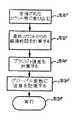
オペレーティングシステムがパワースレッドをイニシエートすると(260)、スレッドはまずメッセージをチェックする(310)。何も受信されない場合、スレッドはオペレーティングシステムへタイムをリターンする(312)。しかしながら、スレッドがメッセージを受信すれば、スレッドはメッセージにあることを判別(この判別は明瞭にするためマルチウェイブランチとして示されているが、コードではシーケンス状に実行される一連の個々のテストとして実行される)し(312)、正しく作動する。このメッセージはエラーメッセージ314、マニュアルノブ移動信号316、リニアポテンショメータ表示信号318(これはパワーヘッドにより周期的に発生される)、フィルボタン表示信号320(これもパワーヘッドにより周期的に発生される)、スタート/ストップボタン押し下げ信号322、または他の数個の信号(一度に多数のメッセージを受信できる)を含むことができる。 When the operating system initiates a power thread (260), the thread first checks for messages (310). If nothing is received, the thread returns time to the operating system (312). However, if the thread receives the message, the thread determines that it is in the message (this determination is shown as a multi-way branch for clarity, but the code shows a series of individual tests that are executed in a sequence). (312) and operate correctly. This message includes an
図16に示すように、メッセージがリニアポテンショメータの表示信号318を含んでいる場合、この表示信号は(EPROM62内に記憶されているキャリブレーションの表示を用いて)等価容積に変換される。次に計算された容積からオフセット値(これは部分的に予め充填された注射器内のイクステンダーの存在を補償する)を引き、この結果をグローバル変数(図14のステップ288においてサーボスレッドによりアクセス可能となっている場合)に記憶する。図11に示されているディスプレイに応答してユーザーが部分的に予め充填されているサイズを識別すると、ステップ326で使用されているオフセット値が発生される。部分的な予め充填された注射器が用いられない場合、このオフセット値は一定のゼロ値にセットされる。調節された容積が一度記憶されると、パワーヘッドスレッドはオペレーティングシステムへタイムをリターンする。 If the message includes a linear
図17に示すように、フィルボタン表示信号が受信される(すなわち受信メッセージがパワーヘッドのキーボード162上のボタン46、47および48のステートを表示する)と、パワーヘッドスレッドはまずどのボタンが押されたかを判別する(330)。 As shown in FIG. 17, when a fill button display signal is received (ie, the received message indicates the state of
高速ボタン48および前進ボタン46または後進ボタン47が押されている場合(332)、スレッドはまず(図15に示されている割り込みルーチンにより発生されるようなモータ速度を表示するグローバル変数を読み出すことにより)モータが最大のラッチ速度になっているかどうかを判別する(334)。最大速度に達していなければ、スレッドは所望の速度を識別するグローバル変数の値を増加し、注射器の端部を示すよう、所望位置を識別するグローバル変数をセットする(更に、モータがまだ動いていない場合、サーボスレッドへスタートサーボメッセージを送る)ことにより、表示方向にモータ速度を増加し(336)、オペレーティングシステムへタイムをリターンする(338)。しかしながら既にモータがラッチ速度に達していれば、フィルボタンの表示信号を処理する最終時に、スレッドはボタンが押されているかどうかを判別する(340)。ボタンが押されていれば、オペレータはモータを最大速度まで加速済みであり、ボタンを押し下げ続けている。この状況下では、モータは最大速度で回転しなければならないので、スレッドはオペレーティングシステムにタイムをリターン(338)するだけである。しかしながら、最終時にボタンが押されていない場合、オペレータはモータを最大速度にラッチし、ボタンを解放し、その後のある時期にモータを停止しようとしてボタンを押していることになる。従ってこのような状況下ではスレッドは(所望速度を表示するグローバル変数をゼロにセットすることにより)モータを停止し(342)、オペレーティングシステムへタイムをリターンする(338)。 If the fast button 48 and the forward button 46 or the
オペレータが前進ボタンまたは後進ボタンのみを押し続けているか、または他の組み合わせのボタンを押している場合、スレッドは(モータ速度を表示するグローバル変数の値をチェックすることにより)モータが回転しているかどうかをまず判別する(346)。モータが回転していなければ、一つのキーストロークではモータの回転をスタートしないので、スレッドはオペレーティングシステムにリターンするだけである(388)。しかしながら、モータが回転していれば、スレッドはフィルボタンの表示信号を処理する最終時にボタンが押されているかどうかを判別する(348)。最終時にボタンが押されていると、オペレータはボタンを押し続けることにより、モータをその時の速度に回転し続けようとしているにすぎない。従ってこの状況では、スレッドはオペレーティングシステムにリターンし(338)、モータの連続回転を可能とする。しかしながら、最終時にボタンが押されていない場合、オペレータはモータを最大速度までラッチし、ボタンを解放し、その後のある時にモータを停止しようとしてボタンを押したはずである。従って、この状況ではスレッドは(所望速度を表示するグローバル変数をゼロにセットすることにより)モータを停止する。 If the operator is pressing and holding only the forward or reverse button, or pressing any other combination of buttons, the sled determines whether the motor is spinning (by checking the value of a global variable that indicates motor speed). Is first determined (346). If the motor is not spinning, one keystroke will not start spinning the motor, and the thread will only return to the operating system (388). However, if the motor is spinning, the thread determines whether the button has been pressed at the end of processing the fill button display signal (348). If the button was depressed at the end, the operator would simply continue to rotate the motor to the current speed by continuing to depress the button. Thus, in this situation, the sled returns (338) to the operating system, allowing continuous rotation of the motor. However, if the button was not depressed at the end, the operator would have latched the motor to maximum speed, released the button, and depressed the button at some later time in an attempt to stop the motor. Thus, in this situation, the sled stops the motor (by setting the global variable indicating the desired speed to zero).
ボタンが押されていなければ(352)、スレッドはモータがラッチ速度になっているかどうかを判別する(354)だけである。ラッチ速度になっていなければ、スロットはモータを停止し(356)、オペレーティングシステムにタイムをリターンする。リターンしない場合は、スレッドは直接リターンして、モータがラッチ速度で回転し続けることができるようにする。 If the button has not been pressed (352), the sled only determines whether the motor is at latch speed (354). If not, the slot stops the motor (356) and returns time to the operating system. If not, the sled returns directly, allowing the motor to continue spinning at the latch speed.
次に図18を参照する。パワーヘッドの背部に取り付けられたマニュアルノブ163(図5)を回転することにより、手動の移動を行うこともできる。上記のようにパワーヘッドCPU160はマニュアルノブの移動をパワーパックのCPU52に定期的にレポートしている。このレポートは最終レポートからのノブから受信された電気パルスの数(パルス数が多ければ回転速度はより速い)および回転方向を識別する。マニュアルノブメッセージが受信(316)されると、パワーヘッド受信スレッドは、まずメッセージに識別されたパルス数から所望のプランジャ速度を計算し(340)、パルス数およびノブの回転方向から所望の終了位置を計算する(342)。これら値は上記のようにサーボスレッドにアクセス可能なグローバル変数内に記憶される(344)。モータがまだ回転していない場合、パワーヘッド受信スレッドはパワースレッドにサーボスタートメッセージも送る。次に、スレッドはオペレーティングシステムへタイムをリターンする(346)。 Next, reference is made to FIG. Manual movement can also be performed by rotating a manual knob 163 (FIG. 5) attached to the back of the powerhead. As described above, the power head CPU 160 periodically reports the movement of the manual knob to the CPU 52 of the power pack. This report identifies the number of electrical pulses received from the knob from the final report (the higher the number of pulses, the faster the speed of rotation) and the direction of rotation. When a manual knob message is received (316), the powerhead receiving thread first calculates (340) the desired plunger speed from the number of pulses identified in the message, and determines the desired end position from the number of pulses and the direction of knob rotation. Is calculated (342). These values are stored (344) in global variables accessible to the servo thread as described above. If the motor is not spinning yet, the powerhead receive thread also sends a servo start message to the power sled. Next, the thread returns time to the operating system (346).
以上で、特定の実施例を参照して、本発明について説明した。しかしながら、ここに具現化した発明の要旨から逸脱することなく、この特定実施例について種々の変形および変更が可能であると理解すべきである。例えば、マニュアル移動ノブ163は速度および方向の制御を可能とする他の制御装置、例えば種々の速度および運動方向に対応する多数の位置に回転し、ロックできるボタンまたはノブまたはオペレータがボタンまたはノブにより所望速度を選択し、別のボタンまたはノブにより所望の方向を別個に選択できるボタンまたはノブの組と置換できる。よって、この特定の実施例は単なる例として解釈すべきであり、特許請求の範囲からのみ決定される保護範囲を制限するものではない。 The invention has been described with reference to a specific embodiment. However, it should be understood that various modifications and changes can be made in this particular embodiment without departing from the spirit of the invention embodied herein. For example, the
10 注射器のハウジング
12 プランジャ
30 コンソール
40 パワーヘッド
50 パワーパックReference Signs List 10
Claims (1)
Translated fromJapanese前記モータを動作させる制御回路を有して、該コントローラは該モータの動作時に該モータの位置をトラッキングし、
前記プランジャに取り付けられるイクステンダーの長さを表わすオフセット値を記憶するメモリとを有し、
前記モータのトラッキング位置に前記記憶オフセット値を適用することにより前記注射器内の前記プランジャの位置を示す値を前記制御回路が計算して、前記プランジャが前記注射器の端部に位置することを前記計算値が示す時は前記プランジャの動作を止めることを特徴とする、
注射装置用コントローラ。A motor for advancing a plunger located in the housing of the syringe toward a nozzle located in front of the syringe for injecting or extracting fluid into and out of an animal subject, and for retracting the plunger from the nozzle; An injection device controller of a type usable with a syringe assembly having an extender attached to a plunger,
A control circuit for operating the motor, wherein the controller tracks the position of the motor when the motor is operating;
A memory for storing an offset value representing the length of the extender attached to the plunger,
The control circuit calculates a value indicating the position of the plunger in the syringe by applying the stored offset value to the tracking position of the motor, and calculates that the plunger is located at the end of the syringe. When the value indicates, the operation of the plunger is stopped,
Controller for injection device.
Applications Claiming Priority (1)
| Application Number | Priority Date | Filing Date | Title |
|---|---|---|---|
| US15782393A | 1993-11-24 | 1993-11-24 |
Related Parent Applications (1)
| Application Number | Title | Priority Date | Filing Date |
|---|---|---|---|
| JP23363194ADivisionJP3853385B2 (en) | 1993-11-24 | 1994-09-28 | Controller for injection device |
Related Child Applications (1)
| Application Number | Title | Priority Date | Filing Date |
|---|---|---|---|
| JP2009120042ADivisionJP5382859B2 (en) | 1993-11-24 | 2009-05-18 | Controller for injection device |
Publications (2)
| Publication Number | Publication Date |
|---|---|
| JP2004275782Atrue JP2004275782A (en) | 2004-10-07 |
| JP4681824B2 JP4681824B2 (en) | 2011-05-11 |
Family
ID=22565427
Family Applications (6)
| Application Number | Title | Priority Date | Filing Date |
|---|---|---|---|
| JP23363194AExpired - LifetimeJP3853385B2 (en) | 1993-11-24 | 1994-09-28 | Controller for injection device |
| JP2004164815AWithdrawnJP2004243149A (en) | 1993-11-24 | 2004-06-02 | Electrically controlled injection device |
| JP2004164810AExpired - LifetimeJP4681824B2 (en) | 1993-11-24 | 2004-06-02 | Controller for injection device |
| JP2005342037AWithdrawnJP2006068555A (en) | 1993-11-24 | 2005-11-28 | Controller for injector |
| JP2009120042AExpired - LifetimeJP5382859B2 (en) | 1993-11-24 | 2009-05-18 | Controller for injection device |
| JP2013057663AWithdrawnJP2013116402A (en) | 1993-11-24 | 2013-03-21 | Controller for injector |
Family Applications Before (2)
| Application Number | Title | Priority Date | Filing Date |
|---|---|---|---|
| JP23363194AExpired - LifetimeJP3853385B2 (en) | 1993-11-24 | 1994-09-28 | Controller for injection device |
| JP2004164815AWithdrawnJP2004243149A (en) | 1993-11-24 | 2004-06-02 | Electrically controlled injection device |
Family Applications After (3)
| Application Number | Title | Priority Date | Filing Date |
|---|---|---|---|
| JP2005342037AWithdrawnJP2006068555A (en) | 1993-11-24 | 2005-11-28 | Controller for injector |
| JP2009120042AExpired - LifetimeJP5382859B2 (en) | 1993-11-24 | 2009-05-18 | Controller for injection device |
| JP2013057663AWithdrawnJP2013116402A (en) | 1993-11-24 | 2013-03-21 | Controller for injector |
Country Status (8)
| Country | Link |
|---|---|
| US (5) | US5681286A (en) |
| EP (2) | EP1323441B1 (en) |
| JP (6) | JP3853385B2 (en) |
| KR (2) | KR100373621B1 (en) |
| AT (2) | ATE339231T1 (en) |
| CA (1) | CA2129284C (en) |
| DE (2) | DE69434850T2 (en) |
| ES (2) | ES2202317T3 (en) |
Families Citing this family (289)
| Publication number | Priority date | Publication date | Assignee | Title |
|---|---|---|---|---|
| US5383858B1 (en) | 1992-08-17 | 1996-10-29 | Medrad Inc | Front-loading medical injector and syringe for use therewith |
| US6402718B1 (en) | 1992-08-17 | 2002-06-11 | Medrad, Inc. | Front-loading medical injector and syringe for use therewith |
| CA2129284C (en)* | 1993-11-24 | 1999-03-09 | Kenneth J. Niehoff | Controlling plunger drives for fluid injection in animals |
| US6221045B1 (en)* | 1995-04-20 | 2001-04-24 | Acist Medical Systems, Inc. | Angiographic injector system with automatic high/low pressure switching |
| US7267666B1 (en)* | 1995-04-20 | 2007-09-11 | Acist Medical Systems, Inc. | Angiographic injector system with multiple processor redundancy |
| US5651775A (en) | 1995-07-12 | 1997-07-29 | Walker; Richard Bradley | Medication delivery and monitoring system and methods |
| AU2551097A (en)* | 1996-03-29 | 1997-10-22 | Robert J. Ashcraft Jr. | Front-loading syringe adapter for front-loading medical injector |
| US5868710A (en)* | 1996-11-22 | 1999-02-09 | Liebel Flarsheim Company | Medical fluid injector |
| US5980573A (en)* | 1997-05-12 | 1999-11-09 | Shaffner; Richard L. | Method and apparatus for fighting infection and maintaining joint spacing in a prosthesis implant area |
| US6796964B2 (en)* | 1997-11-19 | 2004-09-28 | Eidson Associates, Inc | Automatic veterinary medicament delivery system |
| US5954697A (en)* | 1998-03-02 | 1999-09-21 | Srisathapat; Chad | Threaded nut syringe plunger for use with a medication infusion pump |
| US6743202B2 (en) | 1998-06-15 | 2004-06-01 | Medrad, Inc. | Encoding of syringe information |
| JP2002518108A (en)* | 1998-06-15 | 2002-06-25 | メドラッド インコーポレイテッド | Encoding syringe information |
| KR100301657B1 (en)* | 1998-08-14 | 2001-10-27 | 최수봉 | Control method of insulin syringe with pseudo mode |
| US6503573B1 (en)* | 1998-09-29 | 2003-01-07 | The United States Of America As Represented By The Secretary Of The Navy | Bomb annealing of thin films |
| DE19850841A1 (en)* | 1998-11-04 | 2000-05-25 | Eppendorf Geraetebau Netheler | Method for operating an electronic dosing system and dosing system for carrying out the method |
| US8177762B2 (en) | 1998-12-07 | 2012-05-15 | C. R. Bard, Inc. | Septum including at least one identifiable feature, access ports including same, and related methods |
| JP2000189515A (en)* | 1998-12-28 | 2000-07-11 | Nemoto Kyorindo:Kk | Device and method for packing liquid chemicals |
| US6196999B1 (en)* | 1999-02-05 | 2001-03-06 | Liebel-Flarsheim Company | Syringe/plunger coupling |
| US6645177B1 (en) | 1999-02-09 | 2003-11-11 | Alaris Medical Systems, Inc. | Directly engaged syringe driver system |
| US6635030B1 (en) | 1999-04-09 | 2003-10-21 | B.H.B. Llc | Contrast injector for injecting a contrast medium to generate prolonged uniform vascular enhancement |
| US6055985A (en)* | 1999-04-09 | 2000-05-02 | B.H.B., L.C. | Methods for injecting a contrast medium to generate prolonged uniform vascular enhancement |
| US6516749B1 (en) | 1999-06-18 | 2003-02-11 | Salasoft, Inc. | Apparatus for the delivery to an animal of a beneficial agent |
| WO2001008727A1 (en) | 1999-07-30 | 2001-02-08 | Medrad, Inc. | Injector systems and syringe adapters for use therewith |
| US20030216643A1 (en)* | 1999-07-30 | 2003-11-20 | Zatezalo Douglas M. | Programmable injector control |
| US6339718B1 (en)* | 1999-07-30 | 2002-01-15 | Medrad, Inc. | Programmable injector control |
| ES2162573B1 (en)* | 1999-08-04 | 2002-08-01 | Probitas Pharma Sa | ANGIOGRAPHY DEVICE FOR CO2 INJECTION. |
| IT1307266B1 (en)* | 1999-08-13 | 2001-10-30 | Cane Srl | APPARATUS FOR INFUSION OF DRUGS. |
| US6285155B1 (en) | 1999-10-29 | 2001-09-04 | Abbott Laboratories | Pseudo half-step motor drive method and apparatus |
| US6958053B1 (en) | 1999-11-24 | 2005-10-25 | Medrad, Inc. | Injector providing drive member advancement and engagement with syringe plunger, and method of connecting a syringe to an injector |
| US6652489B2 (en) | 2000-02-07 | 2003-11-25 | Medrad, Inc. | Front-loading medical injector and syringes, syringe interfaces, syringe adapters and syringe plungers for use therewith |
| US6626862B1 (en)* | 2000-04-04 | 2003-09-30 | Acist Medical Systems, Inc. | Fluid management and component detection system |
| AU6179001A (en)* | 2000-05-18 | 2001-11-26 | Dentsply Int Inc | Fluid material dispensing syringe |
| US6558352B1 (en)* | 2000-05-30 | 2003-05-06 | Verilogik, Inc. | System and method for variable dosage medicine delivery |
| US6663602B2 (en) | 2000-06-16 | 2003-12-16 | Novo Nordisk A/S | Injection device |
| AUPQ867900A0 (en) | 2000-07-10 | 2000-08-03 | Medrad, Inc. | Medical injector system |
| JP4689142B2 (en)* | 2000-07-22 | 2011-05-25 | イー−ファ フレセニウス カビ インコーポレイテッド | Liquid supply device |
| US6585700B1 (en) | 2000-10-05 | 2003-07-01 | Medrad, Inc. | Syringe, syringe plunger and attachment mechanism for front loading medical injector |
| US20050273079A1 (en)* | 2000-10-10 | 2005-12-08 | Hohlfelder Ingrid E | Fluid material dispensing syringe |
| US7462166B2 (en)* | 2000-12-11 | 2008-12-09 | Medrad, Inc. | Encoding and sensing of syringe information |
| IL156245A0 (en)* | 2000-12-22 | 2004-01-04 | Dca Design Int Ltd | Drive mechanism for an injection device |
| US7018363B2 (en) | 2001-01-18 | 2006-03-28 | Medrad, Inc. | Encoding and sensing of syringe information |
| US7044933B2 (en)* | 2001-03-01 | 2006-05-16 | Scimed Life Systems, Inc. | Fluid injection system for coronary intervention |
| JP3845857B2 (en)* | 2001-03-15 | 2006-11-15 | ニプロ株式会社 | Simple chemical injector |
| WO2002081011A1 (en)* | 2001-04-03 | 2002-10-17 | Medrad, Inc. | Encoding and sensing of syringe information |
| US6817986B2 (en)* | 2001-04-13 | 2004-11-16 | Avant Medical Corp. | Jet injector with data logging system for use in compliance and dose monitoring programs |
| WO2002082113A2 (en)* | 2001-04-30 | 2002-10-17 | Medrad, Inc. | Improved mr injector system with increased mobility and electromagnetic interference mitigation |
| GB2377176B (en)* | 2001-06-30 | 2004-10-20 | John Leyshon Maddocks | Devices for administering material |
| KR100407467B1 (en)* | 2001-07-12 | 2003-11-28 | 최수봉 | Insulin pump operated by remote-controller |
| JP4633095B2 (en)* | 2001-12-13 | 2011-02-16 | パナソニック株式会社 | Medical dosing device |
| US7553294B2 (en) | 2002-05-30 | 2009-06-30 | Medrad, Inc. | Syringe plunger sensing mechanism for a medical injector |
| US7018361B2 (en)* | 2002-06-14 | 2006-03-28 | Baxter International Inc. | Infusion pump |
| AU2011205123B2 (en)* | 2002-08-02 | 2014-05-22 | Liebel-Flarsheim Company | Injector |
| US6929619B2 (en)* | 2002-08-02 | 2005-08-16 | Liebel-Flarshiem Company | Injector |
| US9956377B2 (en) | 2002-09-20 | 2018-05-01 | Angiodynamics, Inc. | Method and apparatus for intra-aortic substance delivery to a branch vessel |
| JP4620929B2 (en)* | 2002-09-26 | 2011-01-26 | 株式会社根本杏林堂 | Chemical injection device |
| JP4198435B2 (en)* | 2002-10-15 | 2008-12-17 | 富士電機エフテック株式会社 | Electric syringe for dental anesthesia |
| JP4286019B2 (en)* | 2003-02-04 | 2009-06-24 | 株式会社根本杏林堂 | Chemical injection system |
| JP4731795B2 (en)* | 2003-02-18 | 2011-07-27 | 株式会社根本杏林堂 | Chemical injection device |
| US7232424B2 (en)* | 2003-04-29 | 2007-06-19 | Cardinal Health 303, Inc. | Syringe pump bearing mechanism |
| US7419478B1 (en) | 2003-06-25 | 2008-09-02 | Medrad, Inc. | Front-loading syringe for medical injector having a flexible syringe retaining ring |
| JP4654129B2 (en) | 2003-07-18 | 2011-03-16 | 株式会社根本杏林堂 | A chemical injection device that displays an image of the input injection conditions |
| US8422413B2 (en)* | 2003-09-18 | 2013-04-16 | Dentsply International Inc. | Process and device for the wireless transmission of dental process data |
| WO2005039675A1 (en)* | 2003-10-29 | 2005-05-06 | Nemoto Kyorindo Co., Ltd | Medicinal liquid infusion apparatus |
| JP2005131007A (en)* | 2003-10-29 | 2005-05-26 | Nemoto Kyorindo:Kk | Medical fluid injection system |
| US7666169B2 (en) | 2003-11-25 | 2010-02-23 | Medrad, Inc. | Syringe and syringe plungers for use with medical injectors |
| USD1031029S1 (en) | 2003-11-25 | 2024-06-11 | Bayer Healthcare Llc | Syringe plunger |
| US7850640B2 (en)* | 2003-11-26 | 2010-12-14 | Acist Medical Systems, Inc. | Device, method, and computer program product for dispensing media as part of a medical procedure |
| US7976793B2 (en)* | 2003-11-27 | 2011-07-12 | Gilson S.A.S. | Electronic pipette |
| US7621892B2 (en)* | 2003-12-31 | 2009-11-24 | Mallinckrodt Inc. | Contrast container holder and method to fill syringes |
| US20050148867A1 (en)* | 2003-12-31 | 2005-07-07 | Liebel-Flarsheim Company | Injector with changeable syringe constants |
| US20050177111A1 (en)* | 2004-02-06 | 2005-08-11 | Shaul Ozeri | Miniature infusion pump |
| US20050182322A1 (en)* | 2004-02-17 | 2005-08-18 | Liebel-Flarsheim Company | Injector auto purge |
| US7771389B2 (en) | 2004-02-17 | 2010-08-10 | Mallinckrodt Inc. | Injector auto purge |
| ES2385140T3 (en)* | 2004-02-18 | 2012-07-18 | Ares Trading S.A. | Portable electronic injection device for injecting liquid medications |
| EP1640029A1 (en)* | 2004-09-24 | 2006-03-29 | Novo Nordisk A/S | Injection device with cap |
| US20060079842A1 (en)* | 2004-10-13 | 2006-04-13 | Liebel-Flarsheim Company | Powerhead control in a power injection system |
| USD550838S1 (en) | 2004-10-13 | 2007-09-11 | Liebel-Flarsheim Company | Power injection system face plate |
| US7507221B2 (en) | 2004-10-13 | 2009-03-24 | Mallinckrodt Inc. | Powerhead of a power injection system |
| USD572818S1 (en) | 2004-10-13 | 2008-07-08 | Mallinckrodt, Inc. | Power injection system face plate |
| ATE444090T1 (en) | 2004-10-21 | 2009-10-15 | Novo Nordisk As | SELECTION MECHANISM FOR A ROTARY PIN |
| JP5147407B2 (en) | 2004-10-21 | 2013-02-20 | ノボ・ノルデイスク・エー/エス | Infusion device with processor for collecting release information |
| WO2006045523A1 (en)* | 2004-10-21 | 2006-05-04 | Novo Nordisk A/S | Medication delivery system with a detector for providing a signal indicative of an amount of an ejected dose of drug |
| WO2006045524A1 (en)* | 2004-10-21 | 2006-05-04 | Novo Nordisk A/S | An injection device with means for signalling the time since the last injection |
| CA2584521C (en)* | 2004-10-27 | 2014-07-29 | E-Z-Em, Inc. | Data collection device, system, method, and computer program product for collecting data related to the dispensing of contrast media |
| US20080004507A1 (en)* | 2004-10-27 | 2008-01-03 | E-Z-Em, Inc. | Data collection device, system, method, and computer program product for collecting data related to the dispensing of contrast media |
| EP1825876A4 (en)* | 2004-11-11 | 2009-09-16 | Nemoto Kyorindo Co Ltd | Chemical liquid infusion system |
| US9022980B2 (en) | 2005-02-01 | 2015-05-05 | Kaleo, Inc. | Medical injector simulation device |
| US8206360B2 (en) | 2005-02-01 | 2012-06-26 | Intelliject, Inc. | Devices, systems and methods for medicament delivery |
| AU2006210865B2 (en)* | 2005-02-01 | 2008-12-04 | Kaleo, Inc. | Devices, systems, and methods for medicament delivery |
| US7731686B2 (en)* | 2005-02-01 | 2010-06-08 | Intelliject, Inc. | Devices, systems and methods for medicament delivery |
| US8231573B2 (en) | 2005-02-01 | 2012-07-31 | Intelliject, Inc. | Medicament delivery device having an electronic circuit system |
| US8361026B2 (en) | 2005-02-01 | 2013-01-29 | Intelliject, Inc. | Apparatus and methods for self-administration of vaccines and other medicaments |
| EP1690560A1 (en)* | 2005-02-14 | 2006-08-16 | Ares Trading S.A. | Medication delivery device |
| EP1690559A1 (en)* | 2005-02-14 | 2006-08-16 | Ares Trading S.A. | Medication delivery device |
| US20100185152A1 (en)* | 2005-02-14 | 2010-07-22 | Novo Nordisk A/S | Dosing Operation In A Medical Device |
| WO2006086980A1 (en)* | 2005-02-21 | 2006-08-24 | Novo Nordisk A/S | A method for ensuring constant speed of a motor in an injection device |
| JP2008531093A (en)* | 2005-02-23 | 2008-08-14 | ノボ・ノルデイスク・エー/エス | Method and apparatus for reversing a piston rod in an injection device |
| US8029482B2 (en) | 2005-03-04 | 2011-10-04 | C. R. Bard, Inc. | Systems and methods for radiographically identifying an access port |
| JP5484674B2 (en) | 2005-03-04 | 2014-05-07 | シー・アール・バード・インコーポレーテッド | Access port and identification method |
| US7947022B2 (en)* | 2005-03-04 | 2011-05-24 | C. R. Bard, Inc. | Access port identification systems and methods |
| US9474888B2 (en) | 2005-03-04 | 2016-10-25 | C. R. Bard, Inc. | Implantable access port including a sandwiched radiopaque insert |
| EP1912135B1 (en)* | 2005-04-06 | 2010-09-15 | Mallinckrodt, Inc. | System and methods for managing information relating to medical fluids and containers therefor |
| US20090043264A1 (en) | 2005-04-24 | 2009-02-12 | Novo Nordisk A/S | Injection Device |
| EP1874393B1 (en) | 2005-04-27 | 2017-09-06 | C.R.Bard, Inc. | Infusion apparatuses |
| US10307581B2 (en) | 2005-04-27 | 2019-06-04 | C. R. Bard, Inc. | Reinforced septum for an implantable medical device |
| EP3884989B1 (en) | 2005-04-27 | 2022-07-13 | C. R. Bard, Inc. | Vascular access port |
| US20060271014A1 (en)* | 2005-05-31 | 2006-11-30 | Mallinckrodt Inc. | Heat retention device for a syringe and methods of use |
| US20070060887A1 (en)* | 2005-08-22 | 2007-03-15 | Marsh David A | Ophthalmic injector |
| US20070088269A1 (en)* | 2005-09-30 | 2007-04-19 | Sherwood Services Ag | Medical pump with lockout system |
| US7534099B2 (en) | 2005-09-30 | 2009-05-19 | Covidien Ag | Aliquot correction for feeding set degradation |
| US8275942B2 (en)* | 2005-12-22 | 2012-09-25 | Intel Corporation | Performance prioritization in multi-threaded processors |
| DE102006006952A1 (en)* | 2006-02-14 | 2007-08-23 | E-Z-Em, Inc. | MRI system |
| JP5062768B2 (en)* | 2006-03-10 | 2012-10-31 | ノボ・ノルデイスク・エー/エス | INJECTION DEVICE AND METHOD FOR REPLACING CARTRIDGE OF THE DEVICE |
| CN101400394B (en)* | 2006-03-10 | 2012-07-04 | 诺沃-诺迪斯克有限公司 | An injection device having a gearing arrangement |
| US8926569B2 (en) | 2006-03-15 | 2015-01-06 | Bayer Medical Care Inc. | Plunger covers and plungers for use in syringes and methods of fabricating plunger covers and plungers for use in syringes |
| CN101405738B (en)* | 2006-03-20 | 2011-11-23 | 诺沃-诺迪斯克有限公司 | Method and electronic module for wirelessly monitoring the operation of a mechanical drug delivery device |
| US20080033368A1 (en)* | 2006-04-04 | 2008-02-07 | Mallinckrodt Inc. | Systems and methods for managing information relating to medical fluids and containers therefor |
| CA2648283A1 (en) | 2006-04-07 | 2007-10-18 | Societe De Commercialisation Des Produits De La Recherche Appliquee Socp Ra Sciences Et Genie S.E.C. | Integrated cement delivery system for bone augmentation procedures and methods |
| US9867646B2 (en) | 2006-04-07 | 2018-01-16 | Gamal Baroud | Integrated cement delivery system for bone augmentation procedures and methods |
| ATE458517T1 (en) | 2006-05-16 | 2010-03-15 | Novo Nordisk As | TRANSMISSION MECHANISM FOR AN INJECTION DEVICE |
| US7815603B2 (en)* | 2006-05-17 | 2010-10-19 | Alcon Research, Ltd. | Ophthalmic injection method |
| US7887521B2 (en)* | 2006-05-17 | 2011-02-15 | Alcon Research, Ltd. | Ophthalmic injection system |
| US7811252B2 (en)* | 2006-05-17 | 2010-10-12 | Alcon Research, Ltd. | Dosage control device |
| JP5253387B2 (en) | 2006-05-18 | 2013-07-31 | ノボ・ノルデイスク・エー/エス | Injection device with mode locking means |
| US8118853B2 (en)* | 2006-06-19 | 2012-02-21 | Cook Medical Technologies Llc | Prosthesis delivery and deployment device |
| USD659234S1 (en)* | 2006-08-11 | 2012-05-08 | Cane S.R.L. | Drug infusion device with a protective cap |
| USD565176S1 (en)* | 2006-08-11 | 2008-03-25 | Cane' S.R.L | Protective cap for a drug infusion device |
| US8038656B2 (en) | 2006-09-29 | 2011-10-18 | Tyco Healthcare Group Lp | Detachable plunger rod syringe |
| US8052655B2 (en) | 2006-09-29 | 2011-11-08 | Novo Nordisk A/S | Injection device with electronic detecting means |
| DE102006047537B4 (en)* | 2006-10-07 | 2024-05-16 | Sanofi-Aventis Deutschland Gmbh | Method and device for determining the position of a stopper of an ampoule for a drug in a medical device and their use, a corresponding medical device and manufacture of a medical device |
| WO2008140546A2 (en)* | 2006-10-16 | 2008-11-20 | Alcon Research, Ltd. | Limited reuse assembly for ophthalmic injection device |
| KR20090091714A (en)* | 2006-10-16 | 2009-08-28 | 알콘 리서치, 리미티드 | Temperature control and thermal sensor assembly for medical devices |
| US9022970B2 (en)* | 2006-10-16 | 2015-05-05 | Alcon Research, Ltd. | Ophthalmic injection device including dosage control device |
| US20080281292A1 (en)* | 2006-10-16 | 2008-11-13 | Hickingbotham Dyson W | Retractable Injection Port |
| WO2008115270A2 (en) | 2006-10-16 | 2008-09-25 | Alcon Research, Ltd. | Ophthalmic injection device including dosage control device |
| CA2664160A1 (en)* | 2006-10-16 | 2008-09-12 | Alcon Research, Ltd. | Method of operating ophthalmic hand piece with disposable end |
| JP2010506673A (en)* | 2006-10-16 | 2010-03-04 | アルコン リサーチ, リミテッド | Universal rechargeable limited reuse assembly for ophthalmic handpieces |
| US9265912B2 (en) | 2006-11-08 | 2016-02-23 | C. R. Bard, Inc. | Indicia informative of characteristics of insertable medical devices |
| US9642986B2 (en) | 2006-11-08 | 2017-05-09 | C. R. Bard, Inc. | Resource information key for an insertable medical device |
| US8454560B2 (en)* | 2006-12-05 | 2013-06-04 | Mallinckrodt Llc | Syringe mount for a medical fluid injector |
| EP2125075A2 (en) | 2007-01-22 | 2009-12-02 | Intelliject, Inc. | Medical injector with compliance tracking and monitoring |
| USD598548S1 (en)* | 2007-02-16 | 2009-08-18 | Nuclea Biomarkers, Llc | Stylet |
| USD942005S1 (en) | 2007-03-14 | 2022-01-25 | Bayer Healthcare Llc | Orange syringe plunger cover |
| USD1002840S1 (en) | 2007-03-14 | 2023-10-24 | Bayer Healthcare Llc | Syringe plunger |
| USD847985S1 (en) | 2007-03-14 | 2019-05-07 | Bayer Healthcare Llc | Syringe plunger cover |
| BRPI0809265A2 (en) | 2007-03-23 | 2014-10-07 | Novo Nordisk As | INJECTION DEVICE INCLUDING A TIGHTENING NUT |
| US20080306443A1 (en)* | 2007-06-06 | 2008-12-11 | Mallinckrodt Inc. | Medical Fluid Injector Having Wireless Pressure Monitoring Feature |
| ES2651269T3 (en) | 2007-06-20 | 2018-01-25 | Medical Components, Inc. | Venous reservoir with molded indications and / or radiopacas |
| WO2009012385A1 (en) | 2007-07-19 | 2009-01-22 | Medical Components, Inc. | Venous access port assembly with x-ray discernable indicia |
| US9610432B2 (en) | 2007-07-19 | 2017-04-04 | Innovative Medical Devices, Llc | Venous access port assembly with X-ray discernable indicia |
| EP2187996B1 (en)* | 2007-08-13 | 2011-10-12 | Mallinckrodt LLC | Drive ram for medical injectors |
| US9108006B2 (en) | 2007-08-17 | 2015-08-18 | Novo Nordisk A/S | Medical device with value sensor |
| US8141417B2 (en)* | 2007-08-23 | 2012-03-27 | Mallinckrodt Llc | Syringe content detection using RF energy |
| JP4994167B2 (en)* | 2007-09-21 | 2012-08-08 | 富士電機エフテック株式会社 | Dental anesthesia syringe |
| US9579496B2 (en) | 2007-11-07 | 2017-02-28 | C. R. Bard, Inc. | Radiopaque and septum-based indicators for a multi-lumen implantable port |
| US9026370B2 (en) | 2007-12-18 | 2015-05-05 | Hospira, Inc. | User interface improvements for medical devices |
| CA2707820A1 (en)* | 2007-12-31 | 2009-07-09 | Novo Nordisk A/S | Electronically monitored injection device |
| WO2009091851A2 (en)* | 2008-01-18 | 2009-07-23 | Mallinckrodt Inc. | Medical fluid injector with auto-calibration based on system wear and usage |
| US8161810B2 (en) | 2008-01-29 | 2012-04-24 | Carefusion 303, Inc. | Syringe imaging systems |
| GB0808389D0 (en)* | 2008-05-09 | 2008-06-18 | Owen Mumford Ltd | Electrically actuated injector |
| US8021344B2 (en) | 2008-07-28 | 2011-09-20 | Intelliject, Inc. | Medicament delivery device configured to produce an audible output |
| USD994111S1 (en) | 2008-05-12 | 2023-08-01 | Kaleo, Inc. | Medicament delivery device cover |
| CA3070618C (en) | 2008-05-20 | 2021-07-20 | Avant Medical Corp. | Autoinjector system |
| US8052645B2 (en) | 2008-07-23 | 2011-11-08 | Avant Medical Corp. | System and method for an injection using a syringe needle |
| ES2397135T3 (en)* | 2008-08-19 | 2013-03-05 | Mallinckrodt Llc | Automatic injector with tilt sensor and syringe communication logic |
| EP2328641B1 (en)* | 2008-08-29 | 2014-12-31 | Novo Nordisk A/S | Medical injection device with time delay indicator |
| US7896843B2 (en)* | 2008-10-15 | 2011-03-01 | Bioquiddity, Inc. | Special purpose fluid dispenser |
| ES2906416T3 (en) | 2008-10-31 | 2022-04-18 | Bard Inc C R | Systems and methods to identify an access road |
| US11890443B2 (en) | 2008-11-13 | 2024-02-06 | C. R. Bard, Inc. | Implantable medical devices including septum-based indicators |
| US8932271B2 (en) | 2008-11-13 | 2015-01-13 | C. R. Bard, Inc. | Implantable medical devices including septum-based indicators |
| CA2722991A1 (en)* | 2008-11-28 | 2010-06-03 | Mallinckrodt Inc. | Workflow driven user interface for medical fluid delivery systems |
| CN102256644B (en)* | 2008-12-22 | 2015-04-29 | 松下健康医疗控股株式会社 | drug delivery device |
| KR101079155B1 (en)* | 2009-02-24 | 2011-11-02 | 김명섭 | Automatic Fine Needle Cell Aspirator |
| US8372036B2 (en) | 2009-05-06 | 2013-02-12 | Alcon Research, Ltd. | Multi-layer heat assembly for a drug delivery device |
| EP2451512A1 (en) | 2009-07-07 | 2012-05-16 | C.R. Bard Inc. | Extensible internal bolster for a medical device |
| EP2456572B1 (en) | 2009-07-24 | 2014-02-26 | BAYER Medical Care Inc. | Multi-fluid medical injector system |
| US8932256B2 (en)* | 2009-09-02 | 2015-01-13 | Medtronic Minimed, Inc. | Insertion device systems and methods |
| US8308679B2 (en)* | 2009-12-30 | 2012-11-13 | Medtronic Minimed, Inc. | Alignment systems and methods |
| US8900190B2 (en)* | 2009-09-02 | 2014-12-02 | Medtronic Minimed, Inc. | Insertion device systems and methods |
| WO2011054110A1 (en) | 2009-11-06 | 2011-05-12 | Socpra Sciences Et Genie S. E. C. | Bone cement delivery system |
| ES2695907T3 (en) | 2009-11-17 | 2019-01-11 | Bard Inc C R | Overmolded access port that includes anchoring and identification features |
| US8177747B2 (en) | 2009-12-22 | 2012-05-15 | Alcon Research, Ltd. | Method and apparatus for drug delivery |
| US8998858B2 (en)* | 2009-12-29 | 2015-04-07 | Medtronic Minimed, Inc. | Alignment and connection systems and methods |
| US8998840B2 (en) | 2009-12-30 | 2015-04-07 | Medtronic Minimed, Inc. | Connection and alignment systems and methods |
| US8858500B2 (en)* | 2009-12-30 | 2014-10-14 | Medtronic Minimed, Inc. | Engagement and sensing systems and methods |
| US9039653B2 (en)* | 2009-12-29 | 2015-05-26 | Medtronic Minimed, Inc. | Retention systems and methods |
| US20120215163A1 (en) | 2009-12-30 | 2012-08-23 | Medtronic Minimed, Inc. | Sensing systems and methods |
| US9421321B2 (en)* | 2009-12-30 | 2016-08-23 | Medtronic Minimed, Inc. | Connection and alignment systems and methods |
| US11497850B2 (en) | 2009-12-30 | 2022-11-15 | Medtronic Minimed, Inc. | Connection and alignment detection systems and methods |
| US8435209B2 (en) | 2009-12-30 | 2013-05-07 | Medtronic Minimed, Inc. | Connection and alignment detection systems and methods |
| US9789247B2 (en) | 2011-12-21 | 2017-10-17 | Deka Products Limited Partnership | Syringe pump, and related method and system |
| US9744300B2 (en) | 2011-12-21 | 2017-08-29 | Deka Products Limited Partnership | Syringe pump and related method |
| US9295778B2 (en) | 2011-12-21 | 2016-03-29 | Deka Products Limited Partnership | Syringe pump |
| CN102939120B (en) | 2010-06-04 | 2016-12-07 | 拜耳医药保健有限责任公司 | Systems and methods for planning and monitoring the use of multiple doses of radiopharmaceuticals on radiopharmaceutical syringes |
| WO2011163511A1 (en)* | 2010-06-23 | 2011-12-29 | Tcb Medical Devices, Llc | Injector for auto-injection of medication and associated method of use |
| USD676955S1 (en) | 2010-12-30 | 2013-02-26 | C. R. Bard, Inc. | Implantable access port |
| USD682416S1 (en) | 2010-12-30 | 2013-05-14 | C. R. Bard, Inc. | Implantable access port |
| US9173999B2 (en) | 2011-01-26 | 2015-11-03 | Kaleo, Inc. | Devices and methods for delivering medicaments from a multi-chamber container |
| US8627816B2 (en) | 2011-02-28 | 2014-01-14 | Intelliject, Inc. | Medicament delivery device for administration of opioid antagonists including formulations for naloxone |
| US8939943B2 (en) | 2011-01-26 | 2015-01-27 | Kaleo, Inc. | Medicament delivery device for administration of opioid antagonists including formulations for naloxone |
| WO2012127046A2 (en) | 2011-03-24 | 2012-09-27 | Sanofi-Aventis Deutschland Gmbh | Device and method for detecting an actuation action performable with a medical device |
| PL2699293T3 (en) | 2011-04-20 | 2019-08-30 | Amgen Inc. | Autoinjector apparatus |
| WO2012172818A1 (en)* | 2011-06-16 | 2012-12-20 | テルモ株式会社 | Color display circuit for liquid crystal display |
| CN106267472B (en) | 2011-07-15 | 2019-08-30 | 赛诺菲-安万特德国有限公司 | Drug delivery device with electromechanical drive mechanism |
| EP2731651B1 (en) | 2011-07-15 | 2020-03-11 | Sanofi-Aventis Deutschland GmbH | A drug delivery device |
| AU2012299169B2 (en) | 2011-08-19 | 2017-08-24 | Icu Medical, Inc. | Systems and methods for a graphical interface including a graphical representation of medical data |
| WO2013026859A1 (en)* | 2011-08-23 | 2013-02-28 | Sanofi-Aventis Deutschland Gmbh | Cartridge with adjustable filling volume |
| US10022498B2 (en) | 2011-12-16 | 2018-07-17 | Icu Medical, Inc. | System for monitoring and delivering medication to a patient and method of using the same to minimize the risks associated with automated therapy |
| US11217340B2 (en) | 2011-12-21 | 2022-01-04 | Deka Products Limited Partnership | Syringe pump having a pressure sensor assembly |
| US10563681B2 (en) | 2011-12-21 | 2020-02-18 | Deka Products Limited Partnership | System, method, and apparatus for clamping |
| US10722645B2 (en) | 2011-12-21 | 2020-07-28 | Deka Products Limited Partnership | Syringe pump, and related method and system |
| US12131826B2 (en) | 2011-12-21 | 2024-10-29 | Deka Products Limited Partnership | Syringe pump and related method |
| JP6069351B2 (en) | 2011-12-29 | 2017-02-01 | ノボ・ノルデイスク・エー/エス | Torsion spring type automatic syringe with dial-up / dial-down administration mechanism |
| JP6306566B2 (en) | 2012-03-30 | 2018-04-04 | アイシーユー・メディカル・インコーポレーテッド | Air detection system and method for detecting air in an infusion system pump |
| USD898908S1 (en) | 2012-04-20 | 2020-10-13 | Amgen Inc. | Pharmaceutical product cassette for an injection device |
| US9522235B2 (en) | 2012-05-22 | 2016-12-20 | Kaleo, Inc. | Devices and methods for delivering medicaments from a multi-chamber container |
| JP6108270B2 (en)* | 2012-06-26 | 2017-04-05 | パナソニックIpマネジメント株式会社 | Chemical inspection device |
| AU2013296555B2 (en) | 2012-07-31 | 2017-10-19 | Icu Medical, Inc. | Patient care system for critical medications |
| US9999718B2 (en) | 2012-08-28 | 2018-06-19 | Osprey Medical, Inc. | Volume monitoring device utilizing light-based systems |
| US11219719B2 (en) | 2012-08-28 | 2022-01-11 | Osprey Medical, Inc. | Volume monitoring systems |
| US10413677B2 (en) | 2012-08-28 | 2019-09-17 | Osprey Medical, Inc. | Volume monitoring device |
| US11116892B2 (en) | 2012-08-28 | 2021-09-14 | Osprey Medical, Inc. | Medium injection diversion and measurement |
| WO2014037946A1 (en) | 2012-09-05 | 2014-03-13 | Elcam Medical Agricultural Cooperative Association Ltd. | Electronic auto-injection device |
| EP2897673B1 (en) | 2012-09-24 | 2020-01-22 | Medline Industries, Inc. | Power injector device and method of use |
| JP5869684B2 (en)* | 2012-09-26 | 2016-02-24 | テルモ株式会社 | Controller for life support apparatus and control method thereof |
| US9174003B2 (en) | 2012-09-28 | 2015-11-03 | Bayer Medical Care Inc. | Quick release plunger |
| GB2526948A (en) | 2012-12-27 | 2015-12-09 | Kaleo Inc | Systems for locating and interacting with medicament delivery devices |
| US11369739B2 (en) | 2013-01-21 | 2022-06-28 | Medline Industries, Lp | Method to provide injection system parameters for injecting fluid into patient |
| CA2904661C (en) | 2013-03-15 | 2022-03-15 | Amgen Inc. | Drug cassette, autoinjector, and autoinjector system |
| AU2014268355B2 (en) | 2013-05-24 | 2018-06-14 | Icu Medical, Inc. | Multi-sensor infusion system for detecting air or an occlusion in the infusion system |
| US10166328B2 (en) | 2013-05-29 | 2019-01-01 | Icu Medical, Inc. | Infusion system which utilizes one or more sensors and additional information to make an air determination regarding the infusion system |
| WO2014194065A1 (en) | 2013-05-29 | 2014-12-04 | Hospira, Inc. | Infusion system and method of use which prevents over-saturation of an analog-to-digital converter |
| KR101448679B1 (en) | 2013-06-26 | 2014-10-08 | (주)디앤케이 | Apparatus for drug leakage protection and method thereof |
| AU2014284577A1 (en)* | 2013-07-03 | 2016-01-21 | Smiths Medical Asd, Inc. | Combination linear potentiometer and syringe thumbpress detection sensor and related systems and methods |
| US9173726B2 (en)* | 2013-07-18 | 2015-11-03 | Christopher R. Sabourin | Illuminated intra-oral delivery device |
| JP6526004B2 (en)* | 2013-08-23 | 2019-06-05 | オスプレイ メディカル インク. | Capacity monitoring device |
| US8932268B1 (en)* | 2013-09-23 | 2015-01-13 | Edward D. Struzinski | Medication cartridge injection assembly |
| ES2901783T3 (en) | 2014-01-27 | 2022-03-23 | Te Pari Products Ltd | A fluid dispenser |
| WO2015127189A1 (en) | 2014-02-21 | 2015-08-27 | Deka Products Limited Partnership | Syringe pump having a pressure sensor assembly |
| EP3110474B1 (en) | 2014-02-28 | 2019-12-18 | ICU Medical, Inc. | Infusion system and method which utilizes dual wavelength optical air-in-line detection |
| AU2015231396B2 (en) | 2014-03-19 | 2018-12-06 | Bayer Healthcare Llc | System for syringe engagement to an injector |
| US11344673B2 (en) | 2014-05-29 | 2022-05-31 | Icu Medical, Inc. | Infusion system and pump with configurable closed loop delivery rate catch-up |
| WO2015200543A2 (en)* | 2014-06-24 | 2015-12-30 | The University Of Toledo | Apparatus and method for injecting bone graft substitute and other materials |
| US9517307B2 (en) | 2014-07-18 | 2016-12-13 | Kaleo, Inc. | Devices and methods for delivering opioid antagonists including formulations for naloxone |
| US11344668B2 (en) | 2014-12-19 | 2022-05-31 | Icu Medical, Inc. | Infusion system with concurrent TPN/insulin infusion |
| EP3058970A1 (en) | 2015-02-19 | 2016-08-24 | Sanofi-Aventis Deutschland GmbH | Data collection device for attachment to an injection device |
| US10850024B2 (en) | 2015-03-02 | 2020-12-01 | Icu Medical, Inc. | Infusion system, device, and method having advanced infusion features |
| US10695495B2 (en) | 2015-03-24 | 2020-06-30 | Kaleo, Inc. | Devices and methods for delivering a lyophilized medicament |
| JP6815650B2 (en)* | 2015-04-16 | 2021-01-20 | 株式会社根本杏林堂 | Chemical injection device, control method of chemical injection device, computer program |
| CN113456946B (en) | 2015-06-09 | 2023-12-26 | 赛诺菲-安万特德国有限公司 | Data acquisition device for attachment to an injection device |
| DK3341048T3 (en) | 2015-08-28 | 2023-08-21 | Bayer Healthcare Llc | SYSTEM AND METHOD FOR VERIFYING INJECTION FLUID FILLING AND IMAGE RECOGNITION OF POWER INJECTOR SYSTEM TRAITS |
| US9480797B1 (en) | 2015-10-28 | 2016-11-01 | Bayer Healthcare Llc | System and method for syringe plunger engagement with an injector |
| CN105771038B (en)* | 2016-03-17 | 2022-09-13 | 南京医科大学第一附属医院 | Accurate trace acupuncture point injection pen |
| CN109069764B (en) | 2016-03-28 | 2021-05-11 | 麦瑞通医疗设备有限公司 | Inflator with removable housing and related method |
| CA3023658C (en) | 2016-05-13 | 2023-03-07 | Icu Medical, Inc. | Infusion pump system and method with common line auto flush |
| WO2017214441A1 (en) | 2016-06-10 | 2017-12-14 | Icu Medical, Inc. | Acoustic flow sensor for continuous medication flow measurements and feedback control of infusion |
| EP3481462B1 (en) | 2016-07-06 | 2021-03-24 | Bayer Healthcare LLC | Contrast heating system with in-line contrast warmer |
| US10532166B2 (en) | 2016-07-08 | 2020-01-14 | Bayer Heatlhcare Llc | System and method for identifying a fill volume of a fluid chamber |
| EP3858395A1 (en)* | 2016-12-01 | 2021-08-04 | Fenwal, Inc. | Fill and finish systems and methods |
| HUE063479T2 (en) | 2017-01-06 | 2024-01-28 | Bayer Healthcare Llc | Syringe plunger with dynamic seal |
| CA3046354A1 (en) | 2017-01-17 | 2018-07-26 | Kaleo, Inc. | Medicament delivery devices with wireless connectivity and event detection |
| EP3961641A1 (en) | 2017-01-24 | 2022-03-02 | Bayer Healthcare LLC | Injector systems and syringe adapters for use therewith |
| CA3050752C (en) | 2017-02-28 | 2022-09-06 | Eli Lilly And Company | Dose detection and drug identification for a medication delivery device |
| WO2019046261A1 (en)* | 2017-08-31 | 2019-03-07 | Bayer Healthcare Llc | System and method for drive member position and fluid injector system mechanical calibration |
| US10089055B1 (en) | 2017-12-27 | 2018-10-02 | Icu Medical, Inc. | Synchronized display of screen content on networked devices |
| US11246625B2 (en) | 2018-01-19 | 2022-02-15 | Boston Scientific Scimed, Inc. | Medical device delivery system with feedback loop |
| US11071831B2 (en) | 2018-02-22 | 2021-07-27 | Eli Lilly And Company | Dose detection system module for medication delivery device |
| HUE061426T2 (en) | 2018-02-27 | 2023-06-28 | Bayer Healthcare Llc | Syringe piston switch mechanism |
| DE102018108203A1 (en) | 2018-04-06 | 2019-10-10 | Fresenius Medical Care Deutschland Gmbh | Method for calibrating a syringe pump, syringe pump and devices |
| EP3593838A1 (en)* | 2018-07-13 | 2020-01-15 | Zyno Medical, Llc | High precision syringe with removable pump unit |
| US11679205B2 (en) | 2018-07-13 | 2023-06-20 | Zyno Medical Llc | High precision syringe with removable pump unit |
| US11929160B2 (en) | 2018-07-16 | 2024-03-12 | Kaleo, Inc. | Medicament delivery devices with wireless connectivity and compliance detection |
| US10525195B1 (en)* | 2018-11-24 | 2020-01-07 | RiteDose, LLC | Injection device |
| WO2020210623A1 (en) | 2019-04-12 | 2020-10-15 | Osprey Medical Inc. | Energy-efficient position determining with multiple sensors |
| US20220296811A1 (en)* | 2019-07-26 | 2022-09-22 | Shenzhen Mindray Scientific Co., Ltd. | Injection pump and infusion pump |
| US20220323672A1 (en)* | 2019-09-02 | 2022-10-13 | Nemera La Verpillière | System and device for dispensing a product |
| CN110731831A (en)* | 2019-09-27 | 2020-01-31 | 卢维红 | Intelligent veterinary automatic injector |
| WO2021094388A1 (en)* | 2019-11-14 | 2021-05-20 | Sanofi | A wireless data communication accessory for a drug delivery device |
| US11278671B2 (en) | 2019-12-04 | 2022-03-22 | Icu Medical, Inc. | Infusion pump with safety sequence keypad |
| BR112022023788A2 (en) | 2020-06-18 | 2022-12-27 | Bayer Healthcare Llc | SYSTEM AND METHOD OF COUPLING A SYRINGE PLUNGER WITH AN INJECTOR |
| CA3189781A1 (en) | 2020-07-21 | 2022-01-27 | Icu Medical, Inc. | Fluid transfer devices and methods of use |
| US11559823B2 (en)* | 2020-09-18 | 2023-01-24 | Asmpt Singapore Pte. Ltd. | Volumetric measurement and regulation device incorporated in a time-pressure dispenser |
| CN112206069B (en)* | 2020-10-12 | 2023-06-02 | 北京天悦生科技有限公司 | Continuous injector control method and device and continuous injector |
| US11135360B1 (en) | 2020-12-07 | 2021-10-05 | Icu Medical, Inc. | Concurrent infusion with common line auto flush |
| CN112827017B (en)* | 2021-01-04 | 2023-03-14 | 杨爱华 | Novel accurate intelligent anaesthetic injection device and use method thereof |
| USD1091564S1 (en) | 2021-10-13 | 2025-09-02 | Icu Medical, Inc. | Display screen or portion thereof with graphical user interface for a medical device |
| CA3241894A1 (en) | 2021-12-10 | 2023-06-15 | Icu Medical, Inc. | Medical fluid compounding systems with coordinated flow control |
| WO2025090056A1 (en)* | 2023-10-23 | 2025-05-01 | Carefusion 303, Inc. | System and method for mixing multiple medications |
Family Cites Families (48)
| Publication number | Priority date | Publication date | Assignee | Title |
|---|---|---|---|---|
| US2702547A (en)* | 1950-02-27 | 1955-02-22 | Antonina S Glass | Motor-driven medical injection apparatus and cartridges therefor |
| US2966175A (en)* | 1958-07-14 | 1960-12-27 | Central Scientific Co | Motor-driven syringe |
| US3739943A (en)* | 1971-02-04 | 1973-06-19 | Sherwood Medical Ind Inc | Infusion system |
| US4006736A (en)* | 1974-11-27 | 1977-02-08 | Medrad, Inc. | Angiographic injector |
| GB1595972A (en)* | 1977-03-09 | 1981-08-19 | Nat Res Dev | Syringe driving apparatus |
| US4424720A (en)* | 1980-12-15 | 1984-01-10 | Ivac Corporation | Mechanism for screw drive and syringe plunger engagement/disengagement |
| US4475666A (en)* | 1981-08-31 | 1984-10-09 | American Hospital Supply Corporation | Automated liquid dispenser control |
| US4529401A (en)* | 1982-01-11 | 1985-07-16 | Cardiac Pacemakers, Inc. | Ambulatory infusion pump having programmable parameters |
| US4562829A (en)* | 1983-02-28 | 1986-01-07 | E. R. Squibb & Sons, Inc. | Strontium-rubidium infusion system |
| US4685903A (en)* | 1984-01-06 | 1987-08-11 | Pacesetter Infusion, Ltd. | External infusion pump apparatus |
| US4854324A (en)* | 1984-01-31 | 1989-08-08 | Medrad, Inc. | Processor-controlled angiographic injector device |
| ATE37661T1 (en)* | 1984-04-14 | 1988-10-15 | Ferring Biotechnik | DEVICE FOR INTERMITTENT APPLICATION OF LIQUID MEDICATIONS. |
| US4741732A (en)* | 1984-05-10 | 1988-05-03 | The University Of Melbourne | Open-loop control of drug infusion |
| EP0164904B1 (en)* | 1984-05-10 | 1991-02-27 | The University Of Melbourne | Method of determining an infusion rate profile and infusion device |
| JPS6185960A (en) | 1984-10-04 | 1986-05-01 | 株式会社 日本メデイカル・サプライ | Drug injector |
| US4652260A (en)* | 1985-03-11 | 1987-03-24 | Strato Medical Corporation | Infusion device |
| US4838857A (en)* | 1985-05-29 | 1989-06-13 | Becton, Dickinson And Company | Medical infusion device |
| GB8525109D0 (en)* | 1985-10-11 | 1985-11-13 | Vickers Plc | Syringe pumps |
| US4636198A (en)* | 1985-11-18 | 1987-01-13 | Mallinckrodt, Inc. | Power syringe with volume reducing adapter |
| JPS63201813A (en)* | 1987-02-18 | 1988-08-19 | Amada Co Ltd | Menu arranging method for soft key device |
| EP0434672B1 (en)* | 1987-06-19 | 1994-12-14 | The University Of Melbourne | Infusion pump |
| JPH0679635B2 (en)* | 1987-07-14 | 1994-10-12 | 東海工業ミシン株式会社 | Data setting device for automatic embroidery machine |
| US4828547A (en)* | 1987-09-28 | 1989-05-09 | Bio-Plexus, Inc. | Self-blunting needle assembly and device including the same |
| US5139484A (en)* | 1988-01-07 | 1992-08-18 | Bernard Hazon | Ambulatory syringe-pusher device for parenteral injections with output servo-controlled by the contents of the syringe |
| JPH01280471A (en) | 1988-05-06 | 1989-11-10 | Terumo Corp | Cylinder pump having flow rate set value locking mechanism |
| JPH01288471A (en) | 1988-05-17 | 1989-11-20 | Sanyo Electric Co Ltd | Printer |
| JPH0241173A (en)* | 1988-07-29 | 1990-02-09 | Terumo Corp | Syringe pump |
| JP2717808B2 (en)* | 1988-08-10 | 1998-02-25 | テルモ株式会社 | Syringe pump |
| US4943279A (en)* | 1988-09-30 | 1990-07-24 | C. R. Bard, Inc. | Medical pump with infusion controlled by a detachable coded label |
| US5078836A (en)* | 1989-07-21 | 1992-01-07 | Hogan Jim S | Method and apparatus for retorting material |
| US4978335A (en)* | 1989-09-29 | 1990-12-18 | Medex, Inc. | Infusion pump with bar code input to computer |
| US5078683A (en)* | 1990-05-04 | 1992-01-07 | Block Medical, Inc. | Programmable infusion system |
| US5135507A (en)* | 1990-05-10 | 1992-08-04 | Habley Medical Technology Corporation | One-piece syringe |
| US5354287A (en)* | 1991-01-16 | 1994-10-11 | Senetek Plc | Injector for delivering fluid to internal target tissue |
| US5256157A (en)* | 1991-01-31 | 1993-10-26 | Baxter International Inc. | Automated infusion pump with replaceable memory cartridges |
| US5236416A (en)* | 1991-05-23 | 1993-08-17 | Ivac Corporation | Syringe plunger position detection and alarm generation |
| US5300031A (en)* | 1991-06-07 | 1994-04-05 | Liebel-Flarsheim Company | Apparatus for injecting fluid into animals and disposable front loadable syringe therefor |
| JP2919121B2 (en)* | 1991-07-03 | 1999-07-12 | 東洋機械金属株式会社 | Display screen control method of molding machine |
| US5425716A (en)* | 1991-08-09 | 1995-06-20 | Atom Kabushiki Kaisha | Infusion apparatus |
| JP2525301B2 (en) | 1991-08-30 | 1996-08-21 | 株式会社ユタックス | Synthetic resin attachment / detachment with tape |
| US5342298A (en)* | 1992-07-31 | 1994-08-30 | Advanced Cardiovascular Systems, Inc. | Automated fluid pressure control system |
| US5383858B1 (en)* | 1992-08-17 | 1996-10-29 | Medrad Inc | Front-loading medical injector and syringe for use therewith |
| US5242408A (en)* | 1992-09-23 | 1993-09-07 | Becton, Dickinson And Company | Method and apparatus for determining pressure and detecting occlusions in a syringe pump |
| JP3660678B2 (en)* | 1992-10-15 | 2005-06-15 | ザ ゼネラル ホスピタル コーポレーション | Infusion pump with electronically loadable drug library |
| US5378231A (en)* | 1992-11-25 | 1995-01-03 | Abbott Laboratories | Automated drug infusion system |
| CA2129284C (en)* | 1993-11-24 | 1999-03-09 | Kenneth J. Niehoff | Controlling plunger drives for fluid injection in animals |
| US5533981A (en)* | 1994-10-06 | 1996-07-09 | Baxter International Inc. | Syringe infusion pump having a syringe plunger sensor |
| US5683367A (en)* | 1995-03-06 | 1997-11-04 | Sabratek Corporation | Infusion pump with different operating modes |
- 1994
- 1994-08-02CACA002129284Apatent/CA2129284C/ennot_activeExpired - Fee Related
- 1994-09-28JPJP23363194Apatent/JP3853385B2/ennot_activeExpired - Lifetime
- 1994-10-12KRKR1019940026043Apatent/KR100373621B1/ennot_activeExpired - Fee Related
- 1994-11-10DEDE69434850Tpatent/DE69434850T2/ennot_activeExpired - Lifetime
- 1994-11-10ESES94308310Tpatent/ES2202317T3/ennot_activeExpired - Lifetime
- 1994-11-10ATAT03075988Tpatent/ATE339231T1/ennot_activeIP Right Cessation
- 1994-11-10EPEP03075988Apatent/EP1323441B1/ennot_activeExpired - Lifetime
- 1994-11-10EPEP94308310Apatent/EP0654279B1/ennot_activeExpired - Lifetime
- 1994-11-10DEDE69433129Tpatent/DE69433129T2/ennot_activeExpired - Lifetime
- 1994-11-10ESES03075988Tpatent/ES2268271T3/ennot_activeExpired - Lifetime
- 1994-11-10ATAT94308310Tpatent/ATE249258T1/ennot_activeIP Right Cessation
- 1995
- 1995-06-06USUS08/467,696patent/US5681286A/ennot_activeExpired - Lifetime
- 1995-06-26USUS08/494,795patent/US5662612A/ennot_activeExpired - Lifetime
- 1997
- 1997-08-28USUS08/919,610patent/US5928197A/ennot_activeExpired - Lifetime
- 2002
- 2002-05-28KRKR1020020029480Apatent/KR100361727B1/ennot_activeExpired - Fee Related
- 2004
- 2004-06-02JPJP2004164815Apatent/JP2004243149A/ennot_activeWithdrawn
- 2004-06-02JPJP2004164810Apatent/JP4681824B2/ennot_activeExpired - Lifetime
- 2005
- 2005-11-28JPJP2005342037Apatent/JP2006068555A/ennot_activeWithdrawn
- 2008
- 2008-01-26USUS12/020,521patent/US7824374B2/ennot_activeExpired - Fee Related
- 2008-03-20USUS12/052,494patent/US7794429B2/ennot_activeExpired - Fee Related
- 2009
- 2009-05-18JPJP2009120042Apatent/JP5382859B2/ennot_activeExpired - Lifetime
- 2013
- 2013-03-21JPJP2013057663Apatent/JP2013116402A/ennot_activeWithdrawn
Also Published As
| Publication number | Publication date |
|---|---|
| JP2009207905A (en) | 2009-09-17 |
| CA2129284A1 (en) | 1995-05-25 |
| DE69433129T2 (en) | 2004-07-08 |
| ATE339231T1 (en) | 2006-10-15 |
| EP0654279B1 (en) | 2003-09-10 |
| JP3853385B2 (en) | 2006-12-06 |
| DE69434850D1 (en) | 2006-10-26 |
| DE69433129D1 (en) | 2003-10-16 |
| JP5382859B2 (en) | 2014-01-08 |
| US20080167615A1 (en) | 2008-07-10 |
| JP2013116402A (en) | 2013-06-13 |
| EP1323441A3 (en) | 2003-11-12 |
| ES2268271T3 (en) | 2007-03-16 |
| ATE249258T1 (en) | 2003-09-15 |
| JP2006068555A (en) | 2006-03-16 |
| EP1323441A2 (en) | 2003-07-02 |
| US5928197A (en) | 1999-07-27 |
| US7794429B2 (en) | 2010-09-14 |
| DE69434850T2 (en) | 2007-09-06 |
| US5681286A (en) | 1997-10-28 |
| EP0654279A2 (en) | 1995-05-24 |
| CA2129284C (en) | 1999-03-09 |
| JPH07184938A (en) | 1995-07-25 |
| US7824374B2 (en) | 2010-11-02 |
| EP1323441B1 (en) | 2006-09-13 |
| JP4681824B2 (en) | 2011-05-11 |
| US5662612A (en) | 1997-09-02 |
| KR100361727B1 (en) | 2002-11-22 |
| KR100373621B1 (en) | 2003-04-21 |
| US20080195048A1 (en) | 2008-08-14 |
| JP2004243149A (en) | 2004-09-02 |
| ES2202317T3 (en) | 2004-04-01 |
| EP0654279A3 (en) | 1996-07-31 |
Similar Documents
| Publication | Publication Date | Title |
|---|---|---|
| JP3853385B2 (en) | Controller for injection device | |
| AU708108B2 (en) | Infusion pump for at least one syringe | |
| CN103550836B (en) | Medical fluid injection system | |
| US6780170B2 (en) | Hydraulic remote for a medical fluid injector | |
| JP4282931B2 (en) | Air shot mechanism for electronic injection device | |
| EP2985047A1 (en) | Chemical injection device and chemical injection system | |
| US20070106153A1 (en) | Powerhead of a Power Injection System | |
| KR20200053709A (en) | Control method of painless anesthetic injection device | |
| KR20200053707A (en) | Control apparatus for automatic injector | |
| KR20200053706A (en) | Automatic injector | |
| KR200391315Y1 (en) | Syringe with indicia | |
| JPH07308377A (en) | Infusion device | |
| JPH0636824B2 (en) | Infusion device | |
| JPH0542211A (en) | Transfusion device | |
| AU5712899A (en) | A plunger pusher module for a syringe pump |
Legal Events
| Date | Code | Title | Description |
|---|---|---|---|
| A521 | Request for written amendment filed | Free format text:JAPANESE INTERMEDIATE CODE: A523 Effective date:20040702 | |
| A621 | Written request for application examination | Free format text:JAPANESE INTERMEDIATE CODE: A621 Effective date:20040702 | |
| A131 | Notification of reasons for refusal | Free format text:JAPANESE INTERMEDIATE CODE: A131 Effective date:20060530 | |
| A601 | Written request for extension of time | Free format text:JAPANESE INTERMEDIATE CODE: A601 Effective date:20060830 | |
| A602 | Written permission of extension of time | Free format text:JAPANESE INTERMEDIATE CODE: A602 Effective date:20060904 | |
| A521 | Request for written amendment filed | Free format text:JAPANESE INTERMEDIATE CODE: A523 Effective date:20061130 | |
| A131 | Notification of reasons for refusal | Free format text:JAPANESE INTERMEDIATE CODE: A131 Effective date:20070302 | |
| A601 | Written request for extension of time | Free format text:JAPANESE INTERMEDIATE CODE: A601 Effective date:20070604 | |
| A602 | Written permission of extension of time | Free format text:JAPANESE INTERMEDIATE CODE: A602 Effective date:20070607 | |
| A601 | Written request for extension of time | Free format text:JAPANESE INTERMEDIATE CODE: A601 Effective date:20070702 | |
| A602 | Written permission of extension of time | Free format text:JAPANESE INTERMEDIATE CODE: A602 Effective date:20070705 | |
| A601 | Written request for extension of time | Free format text:JAPANESE INTERMEDIATE CODE: A601 Effective date:20070802 | |
| A602 | Written permission of extension of time | Free format text:JAPANESE INTERMEDIATE CODE: A602 Effective date:20070807 | |
| A521 | Request for written amendment filed | Free format text:JAPANESE INTERMEDIATE CODE: A523 Effective date:20070903 | |
| A131 | Notification of reasons for refusal | Free format text:JAPANESE INTERMEDIATE CODE: A131 Effective date:20080111 | |
| A601 | Written request for extension of time | Free format text:JAPANESE INTERMEDIATE CODE: A601 Effective date:20080411 | |
| A602 | Written permission of extension of time | Free format text:JAPANESE INTERMEDIATE CODE: A602 Effective date:20080416 | |
| A601 | Written request for extension of time | Free format text:JAPANESE INTERMEDIATE CODE: A601 Effective date:20080512 | |
| A602 | Written permission of extension of time | Free format text:JAPANESE INTERMEDIATE CODE: A602 Effective date:20080515 | |
| A601 | Written request for extension of time | Free format text:JAPANESE INTERMEDIATE CODE: A601 Effective date:20080611 | |
| A602 | Written permission of extension of time | Free format text:JAPANESE INTERMEDIATE CODE: A602 Effective date:20080616 | |
| A521 | Request for written amendment filed | Free format text:JAPANESE INTERMEDIATE CODE: A523 Effective date:20080711 | |
| A02 | Decision of refusal | Free format text:JAPANESE INTERMEDIATE CODE: A02 Effective date:20090116 | |
| A521 | Request for written amendment filed | Free format text:JAPANESE INTERMEDIATE CODE: A523 Effective date:20090518 | |
| A521 | Request for written amendment filed | Free format text:JAPANESE INTERMEDIATE CODE: A821 Effective date:20090706 | |
| A911 | Transfer to examiner for re-examination before appeal (zenchi) | Free format text:JAPANESE INTERMEDIATE CODE: A911 Effective date:20090803 | |
| A912 | Re-examination (zenchi) completed and case transferred to appeal board | Free format text:JAPANESE INTERMEDIATE CODE: A912 Effective date:20090821 | |
| A601 | Written request for extension of time | Free format text:JAPANESE INTERMEDIATE CODE: A601 Effective date:20100723 | |
| A602 | Written permission of extension of time | Free format text:JAPANESE INTERMEDIATE CODE: A602 Effective date:20100729 | |
| A601 | Written request for extension of time | Free format text:JAPANESE INTERMEDIATE CODE: A601 Effective date:20100823 | |
| A602 | Written permission of extension of time | Free format text:JAPANESE INTERMEDIATE CODE: A602 Effective date:20100901 | |
| A601 | Written request for extension of time | Free format text:JAPANESE INTERMEDIATE CODE: A601 Effective date:20100924 | |
| A602 | Written permission of extension of time | Free format text:JAPANESE INTERMEDIATE CODE: A602 Effective date:20100929 | |
| A521 | Request for written amendment filed | Free format text:JAPANESE INTERMEDIATE CODE: A523 Effective date:20101210 | |
| A01 | Written decision to grant a patent or to grant a registration (utility model) | Free format text:JAPANESE INTERMEDIATE CODE: A01 | |
| A61 | First payment of annual fees (during grant procedure) | Free format text:JAPANESE INTERMEDIATE CODE: A61 Effective date:20110207 | |
| R150 | Certificate of patent or registration of utility model | Free format text:JAPANESE INTERMEDIATE CODE: R150 | |
| FPAY | Renewal fee payment (event date is renewal date of database) | Free format text:PAYMENT UNTIL: 20140210 Year of fee payment:3 | |
| S533 | Written request for registration of change of name | Free format text:JAPANESE INTERMEDIATE CODE: R313533 | |
| FPAY | Renewal fee payment (event date is renewal date of database) | Free format text:PAYMENT UNTIL: 20140210 Year of fee payment:3 | |
| R350 | Written notification of registration of transfer | Free format text:JAPANESE INTERMEDIATE CODE: R350 | |
| R250 | Receipt of annual fees | Free format text:JAPANESE INTERMEDIATE CODE: R250 | |
| EXPY | Cancellation because of completion of term |