JP2004274694A - Image encoding method and image decoding method - Google Patents
Image encoding method and image decoding methodDownload PDFInfo
- Publication number
- JP2004274694A JP2004274694AJP2003172545AJP2003172545AJP2004274694AJP 2004274694 AJP2004274694 AJP 2004274694AJP 2003172545 AJP2003172545 AJP 2003172545AJP 2003172545 AJP2003172545 AJP 2003172545AJP 2004274694 AJP2004274694 AJP 2004274694A
- Authority
- JP
- Japan
- Prior art keywords
- image
- picture
- stored
- picture buffer
- memory
- Prior art date
- Legal status (The legal status is an assumption and is not a legal conclusion. Google has not performed a legal analysis and makes no representation as to the accuracy of the status listed.)
- Granted
Links
Images


Landscapes
- Compression Or Coding Systems Of Tv Signals (AREA)
Abstract
Translated fromJapaneseDescription
Translated fromJapanese【0001】
【発明の属する技術分野】
本発明は、動画像を効率良く圧縮する画像符号化方法とそれを正しく復号化して表示する画像復号化方法に関する。
【0002】
【従来の技術】
近年、音声、画像、その他の画素値を統合的に扱うマルチメディア時代を迎え、従来からの情報メディア、つまり新聞、雑誌、テレビ、ラジオ、電話等の情報を人に伝達する手段がマルチメディアの対象として取り上げられるようになってきた。一般に、マルチメディアとは、文字だけでなく、図形、音声、特に画像等を同時に関連づけて表すことをいうが、上記従来の情報メディアをマルチメディアの対象とするには、その情報をディジタル形式にして表すことが必須条件となる。
【0003】
ところが、上記各情報メディアの持つ情報量をディジタル情報量として見積もってみると、文字の場合1文字当たりの情報量は1〜2バイトであるのに対し、音声の場合1秒当たり64Kbits(電話品質)、さらに動画については1秒当たり100Mbits(現行テレビ受信品質)以上の情報量が必要となり、上記情報メディアでその膨大な情報をディジタル形式でそのまま扱うことは現実的では無い。例えば、テレビ電話は、64Kbit/s〜1.5Mbit/sの伝送速度を持つサービス総合ディジタル網(ISDN : Integrated Services Digital Network)によってすでに実用化されているが、テレビ・カメラの映像をそのままISDNで送ることは不可能である。 そこで、必要となってくるのが情報の圧縮技術であり、例えば、テレビ電話の場合、ITU−T(国際電気通信連合 電気通信標準化部門)で国際標準化されたH.261やH.263規格の動画圧縮技術が用いられている。また、MPEG−1規格の情報圧縮技術によると、通常の音楽用CD(コンパクト・ディスク)に音声情報とともに画像情報を入れることも可能となる。
【0004】
ここで、MPEG(Moving Picture Experts Group)とは、動画像信号圧縮の国際規格であり、MPEG−1は、動画像信号を1.5Mbit/sまで、つまりテレビ信号の情報を約100分の1にまで圧縮する規格である。また、MPEG−1規格を対象とする伝送速度が主として約1.5Mbit/sに制限されていることから、さらなる高画質化の要求をみたすべく規格化されたMPEG−2(非特許文献1)では、動画像信号が2〜15Mbit/sに圧縮される。さらに現状では、MPEG−1,MPEG−2と標準化を進めてきた作業グループ(ISO/IEC JTC1/SC29/WG11) によって、MPEG−1,MPEG−2を上回る圧縮率を達成し、更に物体単位で符号化・復号化・操作を可能とし、マルチメディア時代に必要な新しい機能を実現するMPEG−4が規格化された。MPEG−4では、当初、低ビットレートの符号化方法の標準化を目指して進められたが、現在はインタレース画像も含む高ビットレートも含む、より汎用的な符号化に拡張されている。
【0005】
更に近年、MPEG−4の次世代符号化としてJVTと呼ばれる、ITU−TとISO/IEC共同による新しい画像符号化が標準化中である。
図24はピクチャの予測構造・復号順序と表示順序を示す図である。ピクチャとはフレームもしくはフィールドのいずれかを指す用語であり、本明細書ではフレームもしくはフィールドの代わりにピクチャという表現を用いる。また、画像もしくは画面という用語もピクチャと同義語である。図24で斜線のハッチングを施したピクチャは、他のピクチャの符号化・復号化の際に参照されるため、メモリに保存されるピクチャを表す。
【0006】
I0は画面内符号化ピクチャであり、P3、P6、P9は画面間予測符号化ピクチャ(Pピクチャ)である。JVT標準化案では画面間符号化では、従来のMPEG−1/2/4と異なり、複数の符号化済ピクチャから任意のピクチャを参照ピクチャとして1つ選択して、参照ピクチャから予測画像を生成することができる。たとえば、P9ピクチャは、I0、P3、P6の3つのピクチャから任意の1ピクチャを選択してそのピクチャから予測画像を生成することができる。これにより、従来のMPEG−1/2/4よりも適切な予測画像を選択できる可能性が高まり、圧縮率が向上する。B1、B2、B4、B5、B7、B8は画面間双予測符号化ピクチャ(Bピクチャ)であり、画面間予測ピクチャの予測と異なり、複数(2つ)のピクチャを選択してその選択したピクチャから予測画像を生成し符号化する。特に、時間的に前後の2つのピクチャの平均値を予測画像とする内挿予測をすることで、予測画像の精度を大幅に向上でき圧縮率が大幅に向上することが知られている。以下、画面内符号化ピクチャをI、画面間予測符号化ピクチャをP、画面間双予測符号化ピクチャをBという記号を各ピクチャに付与し、各ピクチャの符号化方法を区別する。
【0007】
Bピクチャで時間的に前後のピクチャを予測符号化で参照するためには、時間的に後方のピクチャが先に符号化・復号化されていなければならない。これは、ピクチャの並べ替え(リーオーダリング)と呼ばれ、従来のMPEG−1/2/4からよく行われている。従って、符号化順序(Stream Order)に対し、符号化されたストリームを復号化して表示する順序(Display Order)は図24のピクチャの予測構造・復号順序と表示順序を示す図のように並べ替えられることになる。なお、図24の例におけるBピクチャはストリームを復号化した瞬間に表示されるため、他の画像から参照されない場合はメモリ等に蓄積する必要が無いが、IピクチャやPピクチャは復号化した後、次のBピクチャを復号化した後に表示されるため、メモリに保存する必要がある。
【0008】
以下、ピクチャの予測構造・復号順序と表示順序を示す図においては、用語およびピクチャの斜線のハッチングの意味は図24と同じ意味で統一する。
図25は他のピクチャの予測構造・復号順序と表示順序を示す図である。同図において、図24との違いは、ピクチャ6がPピクチャで無く、Iピクチャであることである。
【0009】
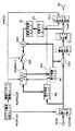
図26は従来の画像符号化方法を実現するための画像符号化装置のブロック図である。以下、図26の従来の画像符号化方法を実現する画像符号化装置の動作について説明する。
ピクチャ構造決定ユニットPicStructは各ピクチャの符号化タイプ(Iピクチャ、Pピクチャ、Bピクチャ)を決定して参照ピクチャ管理ユニットRefPicCtrlにその符号化タイプおよび符号化で参照可能なピクチャを指示し、またピクチャの符号化順序を並べ替えユニットReOrderに通知する。並べ替えユニットReOrderは入力ピクチャPicInの順序を符号化順序に並べ替えて、動き検出ユニットMEおよび減算ユニットSubに並べ替えたピクチャを出力する。動き検出ユニットMEはピクチャメモリPicMem1に保存されたピクチャを参照して適切な参照ピクチャとその画素位置を指し示す動きベクトルMVとを導出し、可変長符号化ユニットVLCとピクチャメモリPicMem1、動き補償ユニットMCに送出する。ピクチャメモリPicMem1は動きベクトルMVに対応する参照ピクチャの画素を動き補償ユニットMCに出力し、動き補償ユニットMCはピクチャメモリPicMem1から得た参照ピクチャの画素と動きベクトルMVとから予測画像を生成する。
【0010】
減算ユニットSubは並べ替えユニットReOrderで並べ替えたピクチャと予測画像の差を計算し、その差を直交変換ユニットTで周波数係数に変換し、更に量子化ユニットQで周波数係数を量子化し、量子化値Coefとする。
逆量子化ユニットIQは量子化値Coefを逆量子化して周波数係数に復元し、更に逆直交変換ユニットITで周波数係数から画素差分値に逆周波数変換する。加算ユニットAddでは予測画像を画素差分値に加算して復号画像を得る。
【0011】
参照ピクチャ管理ユニットRefPicCtrlはピクチャの符号化タイプに応じ、参照ピクチャとして参照するためにピクチャメモリPicMem1に保存すべき復号画像か、ピクチャメモリPicMem1から開放(参照ピクチャとして以後参照されない)すべき復号画像があるかを判断し、その動作をメモリ管理コマンドMMCOとして通知する。
【0012】
スイッチSWは、当該復号画像がメモリ管理コマンドMMCOによって保存が指示された場合にONになり、当該復号画像がピクチャメモリPicMem1に参照ピクチャとして保存される。また、ピクチャメモリPicMem1は、メモリ管理コマンドMMCOによってピクチャメモリPicMem1から開放すべき復号画像が指示された場合は、その復号画像を保存していた領域を開放し他の復号画像をその領域に保存可能にする。
【0013】
可変長符号化ユニットVLCは、量子化値Coef、動きベクトルMV、メモリ管理コマンドMMCOを符号化し、符号化ストリームStrを出力する。
符号化として周波数変換と量子化を伴う例を示したが、周波数変換や量子化を伴わない符号化(DPCMやADPCM、線形予測符号化など)でもよい。また、周波数変換と量子化が一体化したものや、ビットプレーン符号化のように周波数変換の後に量子化を伴わない符号化でもよい。
【0014】
図27はメモリ管理コマンドMMCOの符号例である。符号化・復号化の最初や、GOPの先頭ではピクチャメモリを初期化するために、可変長符号化ユニットVLCは全メモリ開放を意味する’000’を符号化する。また、復号化した画像をピクチャメモリに保存する場合には、可変長符号化ユニットVLCは’01’を符号化する。ピクチャメモリに保存したピクチャを開放する場合は、開放するピクチャ番号を指示しなければならないので、可変長符号化ユニットVLCは’001’の次に開放するピクチャ番号を符号化する。なお、同時に複数ピクチャ開放する場合は開放するコマンドを複数回符号化する必要があり、またピクチャを開放するコマンドに加えて、ピクチャを保存する場合もある。そこで、可変長符号化ユニットVLCは複数のメモリ管理コマンドMMCOを続けて符号化し、メモリ管理コマンドMMCOが完了したことを示す’1’を最後に符号化する。以上のようにして、メモリ管理コマンドMMCOが符号化ストリームStrに符号化される。
【0015】
図28は従来の画像復号化方法を実現する画像復号化装置のブロック図である。同図において、図26の従来の画像符号化方法を実現する画像符号化装置のブロック図と同じ動作をする機器は同じ番号を付し、説明を省略する。
可変長復号化ユニットVLDは符号化ストリームStrを復号化し、メモリ管理コマンドMMCO、動きベクトルMV、量子化値Coefを出力する。ピクチャ時刻Timeは外部から入力され、表示するピクチャを指定する信号である。表示すべきピクチャが復号化した当該ピクチャであればセレクタSelで加算ユニットAddの出力が選択され、表示ユニットDispに送出される。表示すべきピクチャがピクチャメモリPicMem1に保存されているピクチャであればそれがピクチャメモリPicMem1から読み出され、レクタSelで選択され、表示ユニットDispに送出される。
【0016】
なお、上述の通り、ピクチャメモリPicMem1は動きベクトルMVに対応する画素を動き補償ユニットMCに出力し、動き補償ユニットMCはピクチャメモリPicMem1から得た画素と動きベクトルMVとから予測画像を生成する。
また、逆量子化ユニットIQは量子化値Coefを逆量子化して周波数係数に復元し、更に逆直交変換ユニットITで周波数係数から画素差分値に逆周波数変換する。加算ユニットAddはその画素差分値に予測画像を加算して復号画像とする。
【0017】
また、ピクチャメモリPicMem1は、メモリ管理コマンドMMCOによってピクチャメモリPicMem1での開放すべき復号画像が指示された場合は、その復号画像を保存していた領域を開放し他の復号画像をその領域に保存可能にする。
復号化として逆周波数変換と逆量子化を伴う例を示したが、逆周波数変換や逆量子化を伴わない復号化(DPCMやADPCM、線形予測符号化など)でもよい。また、逆周波数変換と逆量子化が一体化したものや、ビットプレーン符号化のように周波数変換の後に逆量子化を伴わない復号化でもよい。
【0018】
以上の図28の従来の画像復号化方法を実現する画像復号化装置により、図24および図25で示す従来のピクチャ符号化タイプの組み合わせは、図26の従来の画像符号化方法を実現する画像符号化装置で符号化した符号化ストリームStrを正しく復号化できることは明らかである。
【0019】
【非特許文献1】
「ISO/IEC 13818−2,Information technology −− Generic coding of moving pictures and associated audio information: Video」(1996年5月15日)
【0020】
【発明が解決しようとする課題】
さて、ピクチャ符号化タイプとして、より柔軟な組み合わせを検討した。
図1はピクチャの従来にはない予測構造・復号順序と表示順序を示す図である。図1ではピクチャ4の前後でBピクチャの予測構造が異なっている。即ち、ピクチャ2のBピクチャは保存されてピクチャ1およびピクチャ3の予測画像として参照されるものである。その結果、各ピクチャの符号化順序および表示順序は図1のようになる。
【0021】
さて、ピクチャ5とピクチャ6は予測符号化で参照されないので保存されないBピクチャである。しかしながら、図24の場合と異なり、復号化時点では他のピクチャの表示時刻であり、まだ表示する時刻になっていない。つまり、ピクチャB5の復号化時点ではピクチャP4を表示しなければならず、ピクチャB6の復号化時点ではピクチャB5を表示しなければならない。一方、ピクチャB5とピクチャB6は保存されないため、ピクチャメモリから表示時刻にピクチャB5とピクチャB6を出力することもできない。従って、予測符号化で参照されないピクチャはピクチャメモリに保存しないため、従来の符号化・復号化の方法ではピクチャB5とピクチャB6を復号化して表示できないことになる。すなわち、図24に示す例のように予測符号化で参照されないピクチャを保存しない場合ではピクチャ0、ピクチャ1、ピクチャ2、ピクチャ4、ピクチャ7だけが表示できることになる。
【0022】
このように、ピクチャ符号化タイプとして、より柔軟な組み合わせを検討すると、復号化して表示できないピクチャが生じてしまうという問題がある。また、表示用に別途、ピクチャメモリを追加し、ピクチャメモリPicMem1に保存されていないピクチャを表示用の別のピクチャメモリに保存すれば表示が可能になるが、この場合、別のピクチャメモリに大きな余分なメモリが必要になる欠点がある。
【0023】
更に、表示用の別のピクチャメモリを導入したとしても、ストリーム途中からの再生において新たな問題が発生する。図2はピクチャの予測構造・復号順序と表示順序を示す図である。同図において、図25との違いは、ピクチャ7の前後で完全に予測構造が独立となることである。I7以降のピクチャはI7より前の時刻のピクチャを符号化・復号化で参照しない。従って、I7ピクチャから復号化を開始すればI7ピクチャ以降が正しく復号化できるため、I7ピクチャはストリーム途中から再生可能であるという特徴を有する。このように、ストリーム途中にIピクチャを挿入することが良く行われ、この途中から再生できる構造をMPEG−2に準じてGOP(グループ オブ ピクチャ)と呼ぶことにする。
【0024】
さて、ストリーム途中から再生するためには、途中から再生した時点でも再生画像が符号化装置と復号化装置との間で一致することを保証しなければならず、そのためにピクチャメモリの全ピクチャ領域を初期化するのが簡単な方法である。しかしながら、ピクチャ6はピクチャ7を復号化した時点ではまだ表示されずにピクチャメモリに格納されているため、単純にピクチャ6の表示前に全てのピクチャメモリを初期化してしまうとピクチャ6の表示時刻にピクチャメモリからピクチャ6を表示できなくなってしまう。
【0025】
そこで、本発明では、画像の符号化あるいは復号化において必要なメモリ量を考慮しながら、復号化して表示できないピクチャが生じないようにすることを目的とする。
【0026】
【課題を解決するための手段】
上記目的を達成するため、本発明の画像符号化装置は、ピクチャバッファに保持されている画像を参照しながら入力画像を予測符号化し、符号化された前記入力画像を復号化する画像符号化方法であって、復号化された画像について、参照用の画像であるか否か及び表示時刻まで保持が必要な出力用の画像であるかを判定し、判定結果に基づいて参照用の画像および出力用の画像を前記ピクチャバッファに保持させることを特徴とする。
【0027】
ここで前記画像符号化方法は、復号化された画像が参照用の画像であるか否かを判定する第1の判定ステップと、復号化された画像が参照用ではなくかつ表示時刻まで保持が必要な出力用の画像であるか否かを判定する第2の判定ステップと、第1の判定ステップにおいて参照用の画像と判定された画像を前記ピクチャバッファに保持させ、第2の判定ステップにおいて出力用の画像と判定された画像を前記ピクチャバッファに保持させるようピクチャバッファを管理する管理ステップとを有する構成としても良い。
【0028】
この構成によれば、復号画像が参照用の画像であるかという判定に加えて、出力用の画像であるかという判定も行って、参照用の画像に加えて予測符号化において参照されないが復号されると同時に表示又は出力することができない画像を出力用画像としてピクチャバッファに格納する。画像符号化に際してこのような判定及びピクチャバッファ管理を行い復号動作を検証しているので、復号化装置において出力用の画像を確実にその表示時刻に表示あるいは出力することができる。
【0029】
ここで、前記ピクチャバッファは一定のサイズを有し、前記画像符号化方法は、さらに、ピクチャバッファに保持されている参照用の画像が参照済となったか否かを判定する第3の判定ステップと、ピクチャバッファに保持されている出力用の画像が出力済となったか否かを判定する第4の判定ステップとを有し、前記管理ステップにおいて、第3及び第4の判定ステップにおける各判定結果に基づいて、前記一定のサイズの範囲内でピクチャバッファ中の画像を保持している領域を再利用する構成としてもよい。
【0030】
この構成によれば、管理ステップにおいて、前記ピクチャバッファの一定のサイズの範囲内で、参照用の画像と前記出力用の画像とを、画像を保持している領域を再利用して格納するので、メモリを無駄に消費することなく復号画像ピクチャバッファを必要最小限のサイズとすることができる。
【0031】
さらに、前記画像符号化方法は、複数の符号化画像からなるシーケンス毎に、当該シーケンスの符号化において一定となる前記サイズを示す情報を符号化する符号化ステップを有するようにしてもよい。
この構成によれば、シーケンス毎に前記サイズが一定となるので、シーケンス毎に予測符号化で用いる画像のタイプを柔軟に定めることができる。
【0032】
また、前記管理ステップにおいて、前記ピクチャバッファ中に新たに画像を格納可能な領域が存在しない場合に、第4の判定ステップにおいて出力済になったと判定された出力用の画像を保持している領域に、第1の判定ステップにおいて参照用の画像と判定された画像および第2の判定ステップにおいて参照用の画像と判定された画像の何れかを格納する構成としてもよい。
【0033】
この構成によれば、ピクチャバッファに格納された出力用の画像の領域のうち既に出力済の画像が格納されている領域に、新たな画像を格納する。つまり出力済の画像が格納されている領域を再利用するので、出力済でない復号画像の表示をより確実にすることができる。
【0034】
さらに、前記管理ステップにおいて、前記ピクチャバッファ中に新たに画像を格納可能な領域が存在しない場合、前記ピクチャバッファに格納された出力用の画像のうち表示順で古い画像を保持している領域に、第1の判定ステップにおいて参照用の画像と判定された画像および第2の判定ステップにおいて出力用の画像と判定された画像の何れかを保持させる構成としてもよい。
【0035】
この構成によれば、出力用の画像のうち表示順で古い画像が格納されている領域には出力済の復号画像が格納されている可能性が高いので、個々の復号画像の表示時刻を正確に判断する構成でなくても、出力済でない復号画像の表示をより確実にすることができる。
【0036】
また、前記画像符号化方法は、さらに、複数の符号化画像を含むシーケンスの途中で入力画像のサイズ変更された場合、出力用の画像を保持している領域のうち、サイズ変更前の画像でかつ格納後に画像の全部又は一部が変更されていない画像を保持している領域以外の領域を開放する開放ステップを有する構成としてもよい。
【0037】
この構成によれば、サイズ変更があったとき、出力用の復号画像は復号画像ピクチャバッファに残すことができるので、サイズ変更の時点で出力済でない画像を削除することなくできるだけ多く出力することができる。
以上の様に、本発明によれば従来では正しく表示不可能であったピクチャも、余分なメモリを持つことなく、開放されたメモリ領域を有効に活用することで表示可能となり、その実用的価値は高い。
【0038】
また本発明の画像復号化方法、画像符号化装置、画像復号化装置、プログラムについても上記と同様の構成、作用、効果を有する。
また、本発明の画像符号化方法又は画像復号化方法は、以下の(1)から(16)の何れかの構成とすることができる。
【0039】
(1)復号化されメモリに保存されている復号化済画像を参照して画像信号を予測符号化する画像符号化方法であって、前記復号化済画像をメモリから参照して予測画像を生成し、前記予測画像と前記画像信号の差を符号化して符号化ストリームとするステップと、前記符号化した前記予測画像と前記画像信号の差を復号化して前記予測画像を加算して復号画像とし、所定の復号画像を前記メモリに格納するステップと、前記メモリの全領域を開放して再利用可能とするか否かを示す指示情報を前記符号化ストリームに含めるステップとを含むことを特徴とする画像符号化方法。
【0040】
(2)復号化済画像を参照して画像信号を予測符号化する画像符号化方法であって、復号化済画像をメモリから参照して予測画像を生成し、前記予測した前記予測画像と前記画像信号の差を符号化して符号化ストリームとし、前記符号化した前記予測画像と前記画像信号の差を復号化して前記予測画像を加算して復号画像とし、予測画像生成のために参照される画像および即座に表示不可能な画像は前記復号画像を前記メモリに格納する画像符号化方法。
【0041】
(3)復号化済画像を参照して画像信号を予測符号化する画像符号化方法であって、復号化済画像をメモリから参照して予測画像を生成し、前記予測した前記予測画像と前記画像信号の差を符号化して符号化ストリームとし、前記符号化した前記予測画像と前記画像信号の差を復号化して前記予測画像を加算して復号画像とし、前記復号画像を前記メモリに格納したり不要になった画像を前記メモリから開放し、前記メモリに前記復号画像を格納する際は前記メモリ内の開放された領域で表示済の画像が保存されていた領域に格納する画像符号化方法。
【0042】
(4)復号化されメモリに保存されている復号化済画像を参照して符号化ストリームを予測復号化する画像復号化方法であって、
前記復号化済画像を前記メモリから参照して予測画像を生成し、前記符号化ストリームを復号化して得られる画像信号に前記予測画像を加算して復号画像とし、所定の復号画像をメモリに格納するステップと、
前記符号化ストリームを復号化して得られるメモリの全領域を開放して再利用可能とするか否かを示す指示情報を基に、前記指示情報が示す情報に基づいた処理を行う処理ステップとを
含むことを特徴とする画像復号化方法。
【0043】
(5)復号化済画像を参照して符号化ストリームを予測復号化する画像復号化方法であって、復号化済画像をメモリから参照して予測画像を生成し、前記符号化ストリームを復号化して前記予測画像を加算して復号画像とし、前記復号画像を前記メモリに格納したり不要になった画像を前記メモリから開放し、前記メモリに前記復号画像を格納する際は前記メモリ内の開放された領域で表示済の画像が保存されていた領域に格納する画像復号化方法。
【0044】
(6)復号化済画像を参照して画像信号を予測符号化する画像符号化方法であって、復号化済画像をメモリから参照して予測画像を生成し、前記予測した前記予測画像と前記画像信号の差を符号化して符号化ストリームとし、前記符号化した前記予測画像と前記画像信号の差を復号化して前記予測画像を加算して復号画像とし、前記復号画像を前記メモリに格納したり不要になった画像を前記メモリから開放し、前記メモリに前記復号画像を格納する際は前記メモリ内の開放された領域で最も古い時刻の画像が保存されていた領域に格納する画像符号化方法。
【0045】
(7)復号化済画像を参照して符号化ストリームを予測復号化する画像復号化方法であって、復号化済画像をメモリから参照して予測画像を生成し、前記符号化ストリームを復号化して前記予測画像を加算して復号画像とし、前記復号画像を前記メモリに格納したり不要になった画像を前記メモリから開放し、前記メモリに前記復号画像を格納する際は前記メモリ内の開放された領域で最も古い時刻の画像が保存されていた領域に格納する画像復号化方法。
【0046】
(8)復号化済画像を参照して画像信号を予測符号化する画像符号化方法であって、復号化済画像をメモリから参照して予測画像を生成し、前記予測した前記予測画像と前記画像信号の差を符号化して符号化ストリームとし、前記符号化した前記予測画像と前記画像信号の差を復号化して前記予測画像を加算して復号画像とし、前記復号画像を前記メモリに格納したり不要になった画像を前記メモリから開放し、前記メモリに前記復号画像を格納する際は前記メモリ内で最初に開放された格納可能領域に格納する画像符号化方法。
【0047】
(9)復号化済画像を参照して符号化ストリームを予測復号化する画像復号化方法であって、復号化済画像をメモリから参照して予測画像を生成し、前記符号化ストリームを復号化して前記予測画像を加算して復号画像とし、前記復号画像を前記メモリに格納したり不要になった画像を前記メモリから開放し、前記メモリに前記復号画像を格納する際は前記メモリ内で最初に開放された格納可能領域に格納する画像復号化方法。
【0048】
(10)復号化済画像を参照して画像信号を予測符号化する画像符号化装置であって、復号化済画像をメモリから参照して予測画像を生成する予測手段と、前記予測手段で予測した前記予測画像と前記画像信号の差を符号化し符号化ストリームとする符号化手段と、前記符号化した前記予測画像と前記画像信号の差を復号化する復号化手段と、前記復号化手段で復号化した前記予測画像と前記画像信号の差と前記予測画像を加算する加算手段と、予測画像生成のために参照される画像および即座に表示不可能な画像をメモリに格納するよう判断する参照画像管理手段と、前記参照画像管理手段の判断に基づいて前記加算手段の加算結果を前記メモリに格納するメモリ手段を備えた画像符号化装置。
【0049】
(11)復号化済画像を参照して画像信号を予測符号化する画像符号化装置であって、復号化済画像をメモリから参照して予測画像を生成する予測手段と、前記予測手段で予測した前記予測画像と前記画像信号の差を符号化し符号化ストリームとする符号化手段と、前記符号化した前記予測画像と前記画像信号の差を復号化する復号化手段と、前記復号化手段で復号化した前記予測画像と前記画像信号の差と前記予測画像を加算する加算手段と、前記加算手段の加算結果をメモリに格納したり不要な画像をメモリから開放するよう判断する参照画像管理手段と、前記参照画像管理手段の判断に基づいて前記加算手段の加算結果をメモリ中の開放された領域であって復号化装置で復号化済画像として外部に出力済である画像が保存されていた領域に格納するメモリ手段を備えた画像符号化装置。
【0050】
(12)復号化済画像を参照して符号化ストリームを予測復号化する画像復号化装置であって、前記符号化ストリームを復号化する復号化手段と、復号化済画像をメモリから参照して予測画像を生成する予測手段と、前記復号化手段で復号化した前記予測画像と前記画像信号の差と前記予測画像を加算する加算手段と、前記加算手段の加算結果をメモリに格納したり不要な画像をメモリから開放するよう判断する参照画像管理手段と、前記参照画像管理手段の判断に基づいて前記加算手段の加算結果をメモリ中の開放された領域であって復号化済画像として外部に出力済の画像が保存されていた領域に格納するメモリ手段を備えた画像復号化装置。
【0051】
(13)復号化済画像を参照して画像信号を予測符号化する画像符号化装置であって、復号化済画像をメモリから参照して予測画像を生成する予測手段と、前記予測手段で予測した前記予測画像と前記画像信号の差を符号化し符号化ストリームとする符号化手段と、前記符号化した前記予測画像と前記画像信号の差を復号化する復号化手段と、前記復号化手段で復号化した前記予測画像と前記画像信号の差と前記予測画像を加算する加算手段と、前記加算手段の加算結果をメモリに格納したり不要な画像をメモリから開放するよう判断する参照画像管理手段と、前記参照画像管理手段の判断に基づいて前記加算手段の加算結果をメモリ中の開放された領域であって時刻が最も古い画像が保存されていた領域に格納するメモリ手段を備えた画像符号化装置。
【0052】
(14)復号化済画像を参照して符号化ストリームを予測復号化する画像復号化装置であって、前記符号化ストリームを復号化する復号化手段と、復号化済画像をメモリから参照して予測画像を生成する予測手段と、前記復号化手段で復号化した前記予測画像と前記画像信号の差と前記予測画像を加算する加算手段と、前記加算手段の加算結果をメモリに格納したり不要な画像をメモリから開放するよう判断する参照画像管理手段と、前記参照画像管理手段の判断に基づいて前記加算手段の加算結果をメモリ中の開放された領域であって時刻が最も古い画像が保存されていた領域に格納するメモリ手段を備えた画像復号化装置。
【0053】
(15)復号化済画像を参照して画像信号を予測符号化する画像符号化装置であって、復号化済画像をメモリから参照して予測画像を生成する予測手段と、前記予測手段で予測した前記予測画像と前記画像信号の差を符号化し符号化ストリームとする符号化手段と、前記符号化した前記予測画像と前記画像信号の差を復号化する復号化手段と、前記復号化手段で復号化した前記予測画像と前記画像信号の差と前記予測画像を加算する加算手段と、前記加算手段の加算結果をメモリに格納したり不要な画像をメモリから開放するよう判断する参照画像管理手段と、前記参照画像管理手段の判断に基づいて前記加算手段の加算結果をメモリ中の開放された領域であってで開放した順序が早い領域に格納するメモリ手段を備えた画像符号化装置。
【0054】
(16)復号化済画像を参照して符号化ストリームを予測復号化する画像復号化装置であって、前記符号化ストリームを復号化する復号化手段と、復号化済画像をメモリから参照して予測画像を生成する予測手段と、前記復号化手段で復号化した前記予測画像と前記画像信号の差と前記予測画像を加算する加算手段と、前記加算手段の加算結果をメモリに格納したり不要な画像をメモリから開放するよう判断する参照画像管理手段と、前記参照画像管理手段の判断に基づいて前記加算手段の加算結果をメモリ中の開放された領域であって開放した順序が早い領域に格納するメモリ手段を備えた画像復号化装置。
【0055】
また、本発明の画像符号化方法及び画像復号化方法をコンピュータに実行させるプログラムを格納する記憶媒体は、以下の(17)から(23)の何れかとしてもよい。
【0056】
(17)上記プログラムはコンピュータに、復号化済画像を参照して画像信号を予測符号化させる画像符号化方法であって、復号化済画像をメモリから参照して予測画像を生成し、前記予測した前記予測画像と前記画像信号の差を符号化して符号化ストリームとし、前記符号化した前記予測画像と前記画像信号の差を復号化して前記予測画像を加算して復号画像とし、予測画像生成のために参照される画像および即座に表示不可能な画像は前記復号画像を前記メモリに格納する画像符号化方法を、行わせるものであることを特徴とする記憶媒体。
【0057】
(18)上記プログラムはコンピュータに、復号化済画像を参照して画像信号を予測符号化させる画像符号化方法であって、復号化済画像をメモリから参照して予測画像を生成し、前記予測した前記予測画像と前記画像信号の差を符号化して符号化ストリームとし、前記符号化した前記予測画像と前記画像信号の差を復号化して前記予測画像を加算して復号画像とし、前記復号画像を前記メモリに格納したり不要になった画像を前記メモリから開放し、前記メモリに前記復号画像を格納する際は前記メモリ内の開放された領域で表示済の画像が保存されていた領域に格納する画像符号化方法を、行わせるものであることを特徴とする記憶媒体。
【0058】
(19)上記プログラムはコンピュータに、復号化済画像を参照して符号化ストリームを予測復号化させる画像復号化方法であって、復号化済画像をメモリから参照して予測画像を生成し、前記符号化ストリームを復号化して前記予測画像を加算して復号画像とし、前記復号画像を前記メモリに格納したり不要になった画像を前記メモリから開放し、前記メモリに前記復号画像を格納する際は前記メモリ内の開放された領域で表示済の画像が保存されていた領域に格納する画像復号化方法を、行わせるものであることを特徴とする記憶媒体。
【0059】
(20)上記プログラムはコンピュータに、復号化済画像を参照して画像信号を予測符号化させる画像符号化方法であって、復号化済画像をメモリから参照して予測画像を生成し、前記予測した前記予測画像と前記画像信号の差を符号化して符号化ストリームとし、前記符号化した前記予測画像と前記画像信号の差を復号化して前記予測画像を加算して復号画像とし、前記復号画像を前記メモリに格納したり不要になった画像を前記メモリから開放し、前記メモリに前記復号画像を格納する際は前記メモリ内の開放された領域で最も古い時刻の画像が保存されていた領域に格納する画像符号化方法を、行わせるものであることを特徴とする記憶媒体。
【0060】
(21)上記プログラムはコンピュータに、復号化済画像を参照して符号化ストリームを予測復号化させる画像復号化方法であって、復号化済画像をメモリから参照して予測画像を生成し、前記符号化ストリームを復号化して前記予測画像を加算して復号画像とし、前記復号画像を前記メモリに格納したり不要になった画像を前記メモリから開放し、前記メモリに前記復号画像を格納する際は前記メモリ内の開放された領域で最も古い時刻の画像が保存されていた領域に格納する画像復号化方法を、行わせるものであることを特徴とする記憶媒体。
【0061】
(22)上記プログラムはコンピュータに、復号化済画像を参照して画像信号を予測符号化させる画像符号化方法であって、復号化済画像をメモリから参照して予測画像を生成し、前記予測した前記予測画像と前記画像信号の差を符号化して符号化ストリームとし、前記符号化した前記予測画像と前記画像信号の差を復号化して前記予測画像を加算して復号画像とし、前記復号画像を前記メモリに格納したり不要になった画像を前記メモリから開放し、前記メモリに前記復号画像を格納する際は前記メモリ内で最初に開放された格納可能領域に格納する画像符号化方法を、行わせるものであることを特徴とする記憶媒体。
【0062】
(23)上記プログラムはコンピュータに、復号化済画像を参照して符号化ストリームを予測復号化させる画像復号化方法であって、復号化済画像をメモリから参照して予測画像を生成し、前記符号化ストリームを復号化して前記予測画像を加算して復号画像とし、前記復号画像を前記メモリに格納したり不要になった画像を前記メモリから開放し、前記メモリに前記復号画像を格納する際は前記メモリ内で最初に開放された格納可能領域に格納する画像復号化方法を、行わせるものであることを特徴とする記憶媒体。
【0063】
また、本発明の画像符号化装置においてストリーム及び画像復号化装置に対するメモリ拘束条件を定義し、ビデオを符号化する方法は、以下の(A1)から(A26)の何れかであってもよい。
【0064】
(A1)ストリーム及び画像復号化装置に対するメモリ拘束条件を定義する、画像符号化方法であって、用いることができる参照ピクチャの最大数を決定するステップと、後方予測参照ピクチャの最大数を設定するステップと、ストリームのヘッダーに後方予測参照ピクチャの前記最大数を入れるステップと、仮想ディスプレイ遅延バッファを生成するステップと、ディスプレイ・カウンタを生成するステップと、前記参照ピクチャに対して十分な記憶空間を割り当てるステップと、前記ビデオを符号化するステップと、を含む画像符号化方法。ここで、仮想・ディスプレイ遅延バッファは、画像符号化装置内のメモリに確保される表示用領域に格納されるべき各表示用ピクチャに対応する仮想的なバッファであり、その表示用ピクチャの出力する順序を示す情報(ピクチャ順序番号等)を保持する。ディスプレイ・カウンタは、仮想的にディスプレイに出力されるべきピクチャのピクチャ順序番号を記憶及び更新する。また、十分な記憶空間とは、参照ピクチャと表示用ピクチャを格納する領域をいう。
【0065】
(A2)参照ピクチャの前記最大数は、デコーダの能力を示すレベル値に応じて決定される、(A1)に記載の画像符号化方法。
【0066】
(A3)後方予測参照ピクチャの前記最大数は、参照ピクチャの前記最大数よりも少ない、(A1)または(A2)に記載の画像符号化方法。
【0067】
(A4)ストリーム全体の前記後方予測は、後方予測参照ピクチャの前記最大数によって制限される、(A1)、(A2)または(A3)に記載の画像符号化方法。
【0068】
(A5)前記仮想・ディスプレイ遅延バッファのサイズは、後方予測参照ピクチャの前記最大数から1を引いたものである、(A1)に記載の画像符号化方法。
【0069】
(A6)前記仮想・ディスプレイ遅延バッファの物理メモリは、ピクチャの表示順序情報だけを含む、(A1)または(A5)に記載の画像符号化方法。
【0070】
(A7)前記ディスプレイ・カウンタは、仮想・ディスプレイ遅延バッファから除去されるピクチャの表示順序情報を記憶するために用いられる、(A1)に記載の画像符号化方法。
【0071】
(A8)前記画像符号化方法は、利用可能な参照ピクチャを用いて符号化対象ピクチャを予測するステップと、前記符号化対象ピクチャを符号化するステップと、前記符号化したピクチャが予測に用いられるかどうかを決定するステップと、前記符号化したピクチャを復号化するステップと、前記復号化したピクチャを前記参照ピクチャ・バッファに記憶するステップと、前記仮想・ディスプレイ遅延バッファを更新するステップと、前記ディスプレイ・カウンタを更新するステップと、を含む(A1)に記載の画像符号化方法。
【0072】
(A9)ピクチャの前記予測は、前記ピクチャが予測符号化される場合には一つ又は複数の参照ピクチャを用いることができる、(A1)または(A8)に記載の画像符号化方法。
【0073】
(A10)前記参照ピクチャは、前記参照ピクチャ・バッファがメモリ拘束条件を満足した場合にのみ用いることができる、(A1)または(A8)に記載の画像符号化方法。
【0074】
(A11)前記参照ピクチャは、前記符号化対象ピクチャが参照ピクチャとして用いられる場合に復号化される、(A1)または(A8)に記載の画像符号化方法。
【0075】
(A12)前記復号化されたピクチャの記憶は、次のピクチャに対する参照ピクチャ数のメモリ拘束条件を決定するステップと、前記参照ピクチャ・バッファから未使用参照ピクチャを除去するステップと、前記復号化したピクチャを前記参照ピクチャ・バッファに加えるステップと、を含む、(A1)、(A8)または(A10)に記載の画像符号化方法。
【0076】
(A13)次のピクチャに対する参照ピクチャの前記最大数は、ストリームに対する参照ピクチャの最大数から前記仮想・ディスプレイ遅延バッファのピクチャ数を引いた数に等しい、(A1)、(A8)、(A10)または(A12)に記載の画像符号化方法。
【0077】
(A14)前記未使用参照ピクチャのディスプレイに対する表示順序情報は、ディスプレイに対する前記表示順序情報が前記ディスプレイ・カウンタの値よりも大きい場合に仮想・ディスプレイ遅延バッファに移動される、(A1)、(A8)、(A10)または(A12)に記載の画像符号化方法。
【0078】
(A15)前記仮想・ディスプレイ遅延バッファは、前記表示順序情報が前記ディスプレイ・カウンタの値より大きい場合には、前記ピクチャの前記時間的情報を記憶する、(A1)または(A8)に記載の画像符号化方法。
【0079】
(A16)前記仮想・ディスプレイ遅延バッファは、前記表示順序情報が前記ディスプレイ・カウンタの値以下である場合には、前記ピクチャの前記表示順序情報を除去する、(A1)、(A8)または(A15)に記載の画像符号化方法。
【0080】
(A17)前記仮想・ディスプレイ遅延バッファの前記ピクチャ数は、前記仮想・ディスプレイ遅延バッファに存在するピクチャの表示順序情報の合計数によって定義される、(A1)、(A8)、(A10)、(A12)または(A13)に記載の画像符号化方法。
【0081】
(A18)前記ディスプレイ・カウンタの表示順序情報は、前記仮想・ディスプレイ遅延バッファがフルであるときか又は符号化されたピクチャ数が前記参照ピクチャの最大数に等しいときに更新を開始する、(A1)または(A8)に記載の画像符号化方法。
【0082】
(A19)前記ディスプレイ・カウンタの表示順序情報は、前記ディスプレイ・カウンタが更新を開始した後に符号化された各ピクチャの表示順序情報に基づいて更新される、(A1)、(A8)または(A18)に記載の画像符号化方法。
【0083】
(A20)前記画像符号化装置のための画像復号化装置は、ストリーム・ヘッダーから最大ポスト・デコーダ・バッファ・サイズを決定するステップと、必要な参照ピクチャの最小数を決定するステップと、参照ピクチャに対して十分な物理メモリ空間を割り当てるステップと、前記ストリームを復号化するステップと、前記ストリームを出力するステップと、を含む(A1)に記載の画像符号化方法。
【0084】
(A21)前記最大ポスト・デコーダ・バッファ・サイズは、前記画像符号化装置によって設定された後方参照ピクチャの最大数である、(A1)または(A20)に記載の画像符号化方法。
【0085】
(A22)必要な参照ピクチャの前記最小数は、同じそのストリームを復号化できる画像復号化装置の能力レベルに対して固定される、(A1)または(A20)に記載の画像符号化方法。
【0086】
(A23)前記画像復号化装置で割り当てられた前記物理メモリ空間は、参照ピクチャ及びポスト・デコーダ・ピクチャの両方を記憶するために用いることができる、(A1)または(A20)に記載の画像符号化方法。
【0087】
(A24)参照ピクチャ及びポスト・デコーダ・ピクチャの両方の合計は、前記割り当てられた物理メモリ空間を超えない、(A1)または(A20)に記載の画像符号化方法。
【0088】
(A25)前記復号化は、復号化されたピクチャの数が前記最大ポスト・デコーダ・バッファ・サイズから1を引いた数に等しいときか又は復号化されたピクチャの合計数が参照ピクチャの前記決定された最小数に等しいときのいずれか早い方に、第1の復号化されたピクチャを出力する、(A1)または(A20)に記載の画像符号化方法。
【0089】
(A26)復号化されたピクチャは、一旦それが出力のために送られたならば前記ポスト・デコーダ・バッファから除去される、(A1)または(A20)に記載の画像符号化方法。
【0090】
また、本発明の画像復号化装置においてストリーム及び画像復号化装置に対するメモリ拘束条件に基づいてストリームを復号化する方法は、以下の(A27)から(A37)の何れかであってもよい。
【0091】
(A27)ストリーム及び画像復号化装置に対するメモリ拘束条件に基づいてストリームを復号化する方法であって、ストリームに用いられる参照ピクチャの最大数を決定するステップと、後方予測参照ピクチャの最大可能数を決定するステップと、ポスト・デコーダ・バッファの最小サイズを計算するステップと、参照ピクチャ・バッファに対して十分な物理メモリ空間を割り当てるステップと、ポスト・デコーダ・バッファに対して十分な物理メモリ空間を割り当てるステップと、ストリームを復号化するステップと、参照ピクチャ・バッファに復号化したピクチャを記憶するステップと、ポスト・デコーダ・バッファに復号化したピクチャを記憶するステップと、復号化したピクチャを出力するステップと、を含む画像復号化方法。ここで、ポスト・デコーダ・バッファは、画像復号化装置内の参照ピクチャメモリにおける表示用領域をいう。
【0092】
(A28)参照ピクチャの前記最大数は、ストリームを復号化できる能力のレベルに応じて画像復号化装置に対して固定される、(A27)に記載の画像復号化方法。
【0093】
(A29)後方予測参照ピクチャの前記最大可能数は、参照ピクチャの前記最大数から1を引いた数によって定義される、(A27)に記載の画像復号化方法。
【0094】
(A30)ポスト・デコーダ・バッファの前記最小サイズは、後方予測参照ピクチャの前記最大可能数から1を引いた数として定義される、(A27)に記載の画像復号化方法。
【0095】
(A31)ポスト・デコーダ・バッファの前記最小サイズをストリームから取得する、(A27)または(A30)に記載の画像復号化方法。
【0096】
(A32)後方予測参照ピクチャの前記最大可能数は、ポスト・デコーダ・バッファの前記最小サイズに1を加えた数によって定義される、(A27)または(A31)に記載の画像復号化方法。
【0097】
(A33)参照ピクチャ・バッファの前記最小サイズは、参照ピクチャの前記最大数として定義される、(A27)に記載の画像復号化方法。
【0098】
(A34)前記参照ピクチャ・バッファは、参照ピクチャを記憶するためにだけ用いられる、(A27)または(A33)に記載の画像復号化方法。
【0099】
(A35)前記ポスト・デコーダ・バッファは、非参照ピクチャを記憶するために用いられる、(A27)、(A30)または(A31)に記載の画像復号化方法。
【0100】
(A36)参照ピクチャは、それが非参照ピクチャと判定されたときに前記参照ピクチャ・バッファから除去される、(A27)、(A32)または(A33)に記載の画像復号化方法。
【0101】
(A37)ポスト・デコーダ・バッファのピクチャは、それが出力された際に前記ポスト・デコーダ・バッファから除去される、(A27)、(A30)、(A31)または(A35)に記載の画像復号化方法。
【0102】
以上の構成によればストリーム及び画像復号化装置の両方に対して同じメモリ拘束条件で動作させることで、ストリームを正しく復号化できることが保証できる。もしそうしなければ、画像復号化装置が復号化過程でストリームを復号化するために十分なメモリ空間を確保できない場合が発生する。
【0103】
【発明の実施の形態】
以下、本発明の実施の形態について、図面を用いて説明する。
【0104】
(実施の形態1)
本発明の実施の形態1を説明する。
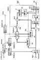
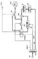
図3は本発明の画像符号化方法を実現する画像符号化装置のブロック図である。同図において、図26の従来の画像符号化方法を実現する画像符号化装置のブロック図と同じ動作をする機器は同じ番号を付し、説明を省略する。
図26の従来の画像符号化方法を実現する画像符号化装置のブロック図との違いは、図3では表示ピクチャ管理ユニットDispPicCtrlが追加され、さらに表示ピクチャ管理ユニットDispPicCtrlの指示が参照ピクチャ管理ユニットRefPicCtrlとピクチャメモリPicMem2に出力されていることである。
【0105】
また、図3に示される画像符号化装置100では新たに、外部から変更されたピクチャサイズを取得するとともに、ピクチャ構造決定ユニットPicStructから各ピクチャの符号化タイプ(Iピクチャ、Pピクチャ、Bピクチャ)を取得して、Iピクチャのタイミングで、変更するピクチャサイズを示す情報を参照ピクチャ管理ユニットRefPicCtrlに出力するピクチャサイズ変更ユニットPicSizeが設けられている。
【0106】
ピクチャメモリPicMem2はピクチャメモリPicMem1と動作が殆ど同じであるため、異なる動作の部分のみ説明する。
表示ピクチャ管理ユニットDispPicCtrlはピクチャ時刻Timeを取得し、参照されないために本来は保存されないピクチャが即座に表示可能かどうか(ピクチャメモリに表示時刻まで格納する必要があるかどうか)を判断する。ピクチャ時刻Timeは外部から入力され、表示するピクチャを指定する信号である。ピクチャ時刻の取得は、例えばピクチャをパケット等の伝送路で伝送するためのシステムが出力する時刻情報から取得してもよいし、あるいは、ビデオストリームとオーディオストリームとを多重化するためのフォーマット中の時刻情報から取得してもよく、あるいは、ビデオストリームのフォーマット中の時刻情報から取得してもよい。また、これらはピクチャ毎に時刻がわかる絶対時刻であっても、ピクチャ間で時間の前後がわかる相対時刻であってもどちらでもよい。更に、通常はピクチャの表示間隔は固定であるため、ピクチャの表示の順序をその時刻として考えても良い。
【0107】
なお、即座に表示が可能である場合とは、加算器Addで加算して得られたピクチャがピクチャ時刻Timeで指示された表示するピクチャと一致する場合である。この場合には、ピクチャメモリPicMem2に、未表示で且つ符号化のために入力されたピクチャより前に表示されるべきピクチャがない場合のことである。即座に表示可能でなければ、参照されない画像であってもピクチャメモリPicMem2に保存するように、表示ピクチャ管理ユニットDispPicCtrlは、参照ピクチャ管理ユニットRefPicCtrlに指示を出す。その結果、即座に表示されないピクチャは参照の有無に関わらず必ずピクチャメモリPicMem2に格納されることになり、復号化装置でピクチャメモリPicMem2からピクチャを表示できるようになる。
【0108】
図4は本発明における参照ピクチャ管理ユニットRefPicCtrlの動作のフローチャートである。
当該復号画像(ピクチャ)が予測画像として参照されるために保存すべきであるかどうかを判断する(Step10)。参照されるならばStep12に進み、そうでなければStep11に進む。
【0109】
Step11では当該復号画像が即座に表示可能であるかどうかを判断する。即座に表示可能とは、復号化した時点でそのまま表示できることであり(例えば図1に示すピクチャ1)、即座に表示不可能とは後で表示しなければならない(例えば図1に示すB5)ことである。即座に表示可能であれば終了し、そうでなければStep12に進む。
【0110】
Step12ではピクチャメモリPicMem2から保存可能な領域を取得し、Step13で取得したピクチャメモリPicMem2の領域に当該復号画像を保存するようにメモリ管理コマンドMMCOで指示を出す。
以上のようにして、即座に表示されないピクチャはピクチャメモリPicMem2に保存し、表示時刻になった時点でピクチャメモリPicMem2からピクチャを表示できるようにすることができる。また、表示用の余分なピクチャメモリを必要とすることがなく、表示のために保存が必要なピクチャを参照用のピクチャメモリに保存することができる。
【0111】
上述したピクチャメモリPicMem2には、予測画像の生成のために参照される参照ピクチャが保存される参照用領域と、表示用ピクチャが保存される表示用領域が存在する。
ところで、前述したGOP(グループ オブ ピクチャ)毎にピクチャサイズの変更を行うことも可能である。このピクチャサイズの変更は、不要になった参照ピクチャの保存されたメモリの参照用領域を全て開放する(再利用可能の状態にする)場合にのみ行われる。
【0112】
しかしながら、このようにピクチャサイズの変更が行われる場合に、上述したように、未表示の表示用ピクチャはメモリ領域に保存されているが、この未表示の表示用ピクチャをどのように扱うべきか(消去すべきか、そのまま表示されるまで保存すべきか)に対する対処方法について明確に決定する必要がある。
【0113】
ここで、ピクチャサイズの変更が行われるときの、メモリへのピクチャの保存状態について段階的に説明する。
図5(a)(b)(c)は、メモリへのピクチャの保存状態を段階的に示す状態図である。
【0114】
図5(a)において、ピクチャ200a、200b、200cは、参照用に保存された参照ピクチャ(予測画像生成のために参照されるピクチャ)であり、ピクチャ201a,201b,201c,201d,201eは、表示用に保存されている表示用ピクチャ(未表示のピクチャ)である。
【0115】
ピクチャ201a,201b,201c,201d,201eは、この順番に表示される。
この図5(a)には、参照ピクチャ200a、200b、200cの保存されているメモリ領域が全て開放されて再利用可能な状態とされた状態が示されている。
【0116】
図5(b)には、図5(a)に示す状態の後にピクチャサイズが変更され、参照ピクチャ200aの保存されていたメモリ領域に、ピクチャサイズが大きくなるよう変更された参照ピクチャ202aが保存され、さらに表示用ピクチャ201aが表示されて、そのメモリ領域が開放された状態が示されている。
【0117】
図5(c)は、図5(b)に示す状態の後、さらに表示用ピクチャ201bの保存されたメモリ領域が開放され、表示用ピクチャ201a,201bの保存されていた開放されたメモリ領域に、画像サイズが大きくなるように変更された参照ピクチャ202bが保存された状態を示しており、小さなメモリ領域203が残っている。この状態で、表示用ピクチャ201cが保存されているメモリ領域を開放しても、新たに参照ピクチャ(ピクチャサイズが大きくなるように変更された)を保存することはできない。
【0118】
このように、ピクチャサイズが変更されると、メモリ内に異なるピクチャサイズのピクチャが混在する(ピクチャサイズが大きくなるように変更された参照ピクチャと、サイズ変更前の未表示の表示用ピクチャ)ことになる。
それによって、メモリが断片的に使用されるようになり、使用できない小さなメモリ領域が発生してメモリの使用効率が劣化する。また、メモリを断片的に使用しないように、発生した小さなメモリ領域がなくなるようにメモリ内でデータの再配置を行うと、メモリアクセスが非常に大きくなってその間の実時間で符号化・復号化動作を実現することが困難である。
【0119】
そのため、ピクチャサイズが変更される場合は、第1の方法として、未表示の表示用ピクチャの保存されている表示用領域と、参照ピクチャの保存されている参照用領域を開放して(再利用可能な状態として)、未表示の表示用ピクチャの表示をあきらめるようにする。このようにすることにより、サイズの異なるピクチャの混在により生じるメモリの断片的な使用を防止することができ、メモリの使用効率の劣化を抑えることができる。
【0120】
上述したピクチャサイズの変更は次のタイミングで行われる。すなわち、図3に示すピクチャサイズ変更ユニットPicSizeが、ピクチャ構造決定ユニットPicStructが決定した各ピクチャの符号化タイプ(Iピクチャ、Pピクチャ、Bピクチャ)と、外部から入力される変更するピクチャサイズとをうけて、Iピクチャのタイミングでピクチャサイズの変更を行う指令を参照ピクチャ管理ユニットRefPicCtrlに出力する。このIピクチャは、例えばGOPの最初に挿入される特別なIピクチャ(IDRピクチャ)である。
【0121】
また、ピクチャサイズが変更される場合は、第2の方法として、メモリの全領域を開放して、未表示の表示用ピクチャをあきらめるようにする手段と、あるいは参照ピクチャが保存された参照用領域のみを開放して、符号化信号(ストリーム)を復号する後述する画像復号化装置(デコーダ)の判断により、サイズ変更前のピクチャで未表示の表示用ピクチャについては表示できるものを表示するようにし、未表示の表示用ピクチャの表示を義務付けないようにする手段とを切り替えるようにしている。このとき、画像復号化装置は、未表示のピクチャについて例えば損傷していないピクチャなどの表示可能なピクチャを表示順序に従って表示するようにする。
【0122】
このような切り替えを行うとき、メモリの全領域を開放する方法と、参照ピクチャが保存された参照用領域のみを開放する方法のいずれの方法で行うかを示す指示情報(フラグ)もしくは他の識別できるような情報を画像符号化装置100から出力されるストリームStrに含めて配置する。
【0123】
画像復号化装置側では、ストリームに配置された指示情報に基づいた処理を行う。
この指示情報が示す2つの方法を切り替える際の判断基準の例としては、いずれの方法で行うかをアプリケーションによってコンテンツを作る人が決めるようにするか、メモリに余裕があれば参照用領域のみを開放して未表示の表示用ピクチャが保存されている表示用領域を開放することはしない(メモリの全領域を開放することはしない)か、あるいは、ピクチャサイズが小さくなるよう変更される場合は、参照用領域のみを開放して未表示の表示用ピクチャが保存されている表示用領域を開放することはしない(メモリの全領域を開放することはしない)などが考えられる。
以上の構成により、従来の課題を解決する画像符号化装置が実現できる。
【0124】
(実施の形態2)
本発明の実施の形態2について説明する。
本実施の形態では、図3で示した表示ピクチャ管理ユニットDispPicCtrlが、ピクチャメモリPicMem2に対して、開放したメモリにピクチャを保存する場合に、表示していないピクチャの領域には新たなピクチャを保存しないように指示する。通常、ピクチャの領域が開放されても、その領域に新しいピクチャが保存(上書き)されない限りは直前に保存したピクチャが再生できる。そこで、仮に表示していないピクチャの保存されたメモリ領域が開放されたとしても、そのメモリ領域には新しいピクチャを保存せず、表示済のピクチャが保存されていた領域に新しいピクチャを保存することで、表示時刻になった時点で、開放されているが、まだ上書きされずに残っている未表示のピクチャを表示することができる。このピクチャメモリの開放されたピクチャ領域にあるピクチャを表示用ピクチャと呼ぶことにする。なお、表示済とは、表示装置への出力済と実質的に同義であり、復号化装置においては実際に表示したこと(あるいは表示装置へ出力したこと)を意味し、符号化装置においては実際には表示(あるいは出力)するわけではなくピクチャ時刻Timeに指定されたときに表示したもの(あるいは出力したもの)とみなして扱うことを意味する。
【0125】
図6は本実施の形態における画像符号化装置100の動作を示すフローチャートである。本実施の形態は、開放領域のメモリに保存されているピクチャが表示済みかどうかで、ピクチャの保存を決定することを特徴とする。
まず、Step20で当該復号画像がピクチャメモリPicMem2に保存するものかどうかをメモリ管理コマンドMMCOの指示に基づき判断する。
【0126】
保存する場合には、開放されたピクチャ領域を取得し(Step21)、開放されてピクチャ領域に保存されていたピクチャが表示済であるかどうかを確認する(Step22)。まだ表示されていなければ、Step21に戻り表示済のピクチャが保存されていた開放領域を見つけるまで処理を繰り返す。
【0127】
表示済のピクチャが保存されていた開放領域を見つけたならば、その領域に復号画像を保存する(Step23)。
このようにすることにより、未表示のピクチャが表示済みになると、その表示済のピクチャの保存されている領域が再利用されるため、未表示のピクチャは、上書きされることなく表示されるまでメモリに保存される。
【0128】
なお、メモリに保存されているピクチャが表示済みかどうかは、表示ピクチャ管理ユニットDispPicCtrlにおいて表示したかどうかの情報を管理することによって判断することができる。
また、ピクチャ領域が開放領域かどうかは、ピクチャ領域毎に開放されているかどうかの情報、例えば「used(参照ピクチャとして使用可能)」か「unused(以後、参照ピクチャとして参照されない)」なのかをメモリ管理コマンドMMCOに従ってピクチャメモリPicMem2において保持し、この保持されている情報を参照することにより判断することができる。
【0129】
以上の構成により、従来の課題を解決する画像符号化装置が実現できる。
以上のようにして、表示されていないピクチャへの新たなピクチャの上書きを防止し、表示時刻になった時点で開放済であるが上書きされていない領域からピクチャを表示することができる。また、余分なメモリを必要とすることがなく、表示のために保存が必要なピクチャを保存することができる。
なお、ピクチャサイズが変更になった場合の動作は、実施の形態1と同様なので説明を省略する。
【0130】
(実施の形態3)
本発明の実施の形態3を説明する。
図7は本発明の実施の形態3における画像符号化装置100の動作を示すフローチャートである。本実施の形態は、メモリを開放した時刻によってピクチャの保存を決定することを特徴とする。
まず、Step30で当該復号画像がピクチャメモリPicMem2に保存するものかどうかをメモリ管理コマンドMMCOの指示に基づき判断する。
【0131】
保存する場合には、最も古い時刻に開放されたピクチャメモリ領域を取得し(Step31)、その領域に復号画像を保存する(Step32)。
また、最も古い時刻に開放されたメモリ領域をピクチャの保存領域とするのではなく、最も古い時刻にピクチャが復号化され保存されたメモリ領域、あるいは最も表示時刻が古いピクチャの保存されているメモリ領域をピクチャの保存領域としてもよい。これらのメモリ領域は、そこに保存されているピクチャが既に表示されている可能性が高いからである。
【0132】
表示時刻の情報はシステムが管理するため、画像復号化装置の作り方によっては表示時刻を入手することが困難である。最も古い時刻に保存されたピクチャの領域が、より新しい時刻に保存された領域よりも古い表示時刻のピクチャが保存されていた可能性が高い。古い表示時刻のピクチャが既に表示されている可能性が高いのは当然であるため、最も古い時刻に保存されたピクチャは既に表示されている可能性が高い。従って、最も古い時刻に保存されたピクチャの領域に当該復号画像を保存することで、表示されていないピクチャを上書きしない可能性が高くなる。また、最も古い時刻がピクチャを符号化した時刻の最も古い時刻である場合、例えば最も古い時刻に符号化されたかどうかはピクチャの予測構造・復号順序から判断することが可能である。
【0133】
また、これらの最も古い時刻は時刻である必要はなく、最も古い順序であってもよく、例えば表示される順序が最も古い順序であってもよいのは当然である。例えば表示順序が古いピクチャが既に表示されている可能性が高く、表示されたか否かに関わらず、表示順序が古いピクチャの保存されているメモリ領域から順にメモリの保存領域として再利用される。更に、通常はピクチャの表示間隔は固定であるため、ピクチャの表示の順序をその時刻として考えても良い。
【0134】
以上のようにして、表示されていないピクチャへの新たなピクチャの上書きを防止し、表示時刻になった時点で開放済であるが上書きされていない領域からピクチャを表示することができる。また、余分なメモリを必要とすることがなく、表示のために保存が必要なピクチャを保存することができる。また、ピクチャメモリPicMem2に保存されているピクチャが表示されているかどうかに関係なく、表示するために保存しておくべきピクチャの保存の処理をすることができる。なお、最も古い時刻が表示の時刻の最も古い時刻である場合、例えば表示ピクチャ管理ユニットDispPicCtrlにおいて表示したかどうかの情報を管理することによって、最も古い時刻に保存されたピクチャかどうかを判断することができる。
なお、ピクチャサイズが変更になった場合の動作は、実施の形態1と同様なので説明を省略する。
【0135】
(実施の形態4)
本発明の実施の形態4を説明する。
図8は本発明の実施の形態4における画像符号化装置100の動作を示すフローチャートである。本実施の形態は、メモリを開放した順番によってピクチャの保存を決定することを特徴とする。
まず、Step40で当該復号画像がピクチャメモリPicMem2に保存するものかどうかをメモリ管理コマンドMMCOの指示に基づき判断する。
【0136】
保存する場合には、開放された領域の中で、最初に開放されたピクチャ領域を取得し(Step41)、その領域に復号画像を保存する(Step42)。
表示時刻の情報はシステムが管理するため、ビデオ復号化装置の作り方によっては表示時刻を入手することが困難である。最初に開放されたピクチャの領域が、後で開放された領域よりも古い表示時刻のピクチャが保存されていた可能性が高い。すなわち、最初に開放されたピクチャは既に表示されている可能性が高い。従って、最初に開放されたピクチャの領域に当該復号画像を保存することで、表示されていないピクチャに対して上書きしない可能性が高くなる。
【0137】
なお、ピクチャ領域が最初に開放されたピクチャ領域かどうかは、ピクチャ領域毎に開放されているかどうかの情報、例えば「used:開放されていない(参照ピクチャとして使用可能)」か「unused:開放済み(以後、参照ピクチャとして参照されない)」かをメモリ管理コマンドMMCOに従ってピクチャメモリPicMem2において開放した順序を含めて保持し、この保持されている情報を参照することにより判断することができる。あるいは、ピクチャ領域の使用方法を所定の手順に固定し、その手順に従って最初に開放されたピクチャ領域かどうかを判断すればよい。例えば、ピクチャメモリPicMem2を、新規のものが記憶されると記憶した時刻が古い記憶内容が順に破棄され、常に最新の一定フレーム数(またはピクチャ数)の画像が保存される先入れ先出し方式(FIFO)のメモリとして、最初に開放されたピクチャ領域かどうかを判断すればよい。 以上のようにして、表示されていないピクチャへの新たなピクチャの上書きを防止し、表示時刻になった時点で、開放済であるが上書きされていない領域からピクチャを表示することができる。
なお、ピクチャサイズが変更になった場合の動作は、実施の形態1と同様なので説明を省略する。
【0138】
(実施の形態5)
本発明の実施の形態5を説明する。
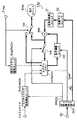
図9は本発明の画像復号化方法を実現する画像復号化装置のブロック図である。同図において、図3の本発明の画像符号化方法を実現する画像符号化装置のブロック図および図28の従来の画像復号化方法を実現する画像復号化装置のブロック図と同じ動作をする機器は同じ番号を付し、説明を省略する。
【0139】
図9の画像復号化装置150において、従来例を示す図28と異なる点は、図9では、外部から取得した変更するピクチャサイズ、および可変長復号化ユニットVLDから取得したメモリ管理コマンドMMCOを基に、特別なIピクチャ(IDR(Instantaneous Decoding Refresh)ピクチャ)のタイミングでピクチャサイズを変更する指令をピクチャメモリPicMem2に出力するピクチャサイズ変更検出ユニットPicSizeDetと、表示ピクチャ管理ユニットDispPicCtrlが新たに設けられている。
【0140】
表示ピクチャ管理ユニットDispPicCtrlはピクチャメモリPicMem2における開放した領域に対してピクチャを保存する場合に、表示していないピクチャの領域には新たなピクチャを保存しないように指示する。通常、ピクチャの領域が開放されても、その領域に新しいピクチャが保存(上書き)されない限りは直前に保存したピクチャのデータがメモリ内に残っており再生できる。そこで、仮に表示していないピクチャが開放されたとしても、表示済のピクチャが保存されていた領域に新しいピクチャを保存することで、表示時刻になった時点で開放されているがまだ上書きされずに残っている表示されていないピクチャを表示することができる。なお、表示済は、表示装置への出力済と実質的に同義である.
このようにすることにより、未表示のピクチャが表示済みになると、その表示済のピクチャの保存されているメモリ領域が再利用されるため、未表示のピクチャは、上書きされることなく表示されるまでメモリに保存される。
【0141】
以上の構成により、従来の課題を解決する画像復号化装置が実現できる。なお、画像復号化装置150は、実施の形態3、および実施の形態4に示した画像符号化装置100により符号化された符号化信号を復号するようにしてもよい。その場合にピクチャメモリの利用についての動作は、実施の形態3および実施の形態4に示された画像符号化装置と同様である。即ち、このピクチャメモリで開放された(以後、参照されない)ピクチャの再利用については、実施の形態1から実施の形態3に記載した方法で新たにピクチャを保存する領域の決定方法のいずれかを使うこともできる。
【0142】
上述した実施の形態3および実施の形態4に示された画像符号化装置により符号化された符号化信号を復号するときのメモリへのピクチャの保存方法について説明する。
最初に、実施の形態3に示された画像符号化装置により符号化された符号化信号を復号するときのメモリへのピクチャの保存方法について説明する。
【0143】
まず、画像復号化装置150における加算ユニットAddより出力される復号画像がピクチャメモリPicMem2に保存するものかどうかをメモリ管理コマンドMMCOの指示に基づき判断する。
保存する場合には、最も古い時刻に開放されたピクチャメモリ領域を取得し、その領域に復号画像を保存する。
【0144】
このとき、最も古い時刻に開放されたメモリ領域をピクチャの保存領域とするのではなく、最も古い時刻にピクチャが復号化され保存されたメモリ領域、あるいは最も表示時刻が古いピクチャの保存されているメモリ領域をピクチャの保存領域としてもよい。これらのメモリ領域は、そこに保存されているピクチャが既に表示されている可能性が高いからである。
【0145】
表示時刻の情報はシステムが管理するため、ビデオ復号化装置の作り方によっては表示時刻を入手することが困難である。最も古い時刻に保存されたピクチャの領域が、より新しい時刻に保存された領域よりも古い表示時刻のピクチャが保存されていた可能性が高い。古い表示時刻のピクチャが既に表示されている可能性が高いのは当然であるため、最も古い時刻に保存されたピクチャは既に表示されている可能性が高い。従って、最も古い時刻に保存されたピクチャの領域に当該復号画像を保存することで、表示されていないピクチャを上書きしない可能性が高くなる。また、最も古い時刻がピクチャを符号化した時刻の最も古い時刻である場合、例えば最も古い時刻に符号化されたかどうかはピクチャの予測構造・復号順序から判断することが可能である。
【0146】
また、これらの最も古い時刻は時刻である必要はなく、最も古い順序であってもよく、例えば表示される順序が最も古い順序であってもよいのは当然である。例えば表示順序が古いピクチャが既に表示されている可能性が高く、表示されたか否かに関わらず、表示順序が古いピクチャの保存されているメモリ領域から順にメモリの保存領域として再利用される。更に、通常はピクチャの表示間隔は固定であるため、ピクチャの表示の順序をその時刻として考えても良い。
【0147】
以上のようにして、表示されていないピクチャへの新たなピクチャの上書きを防止し、表示時刻になった時点で開放済であるが上書きされていない領域からピクチャを表示することができる。また、余分なメモリを必要とすることがなく、表示のために保存が必要なピクチャを保存することができる。
【0148】
また、ピクチャメモリPicMem2に保存されているピクチャが表示されているかどうかに関係なく、表示するために保存しておくべきピクチャの保存の処理をすることができる。なお、最も古い時刻が表示の時刻の最も古い時刻である場合、例えば表示ピクチャ管理ユニットDispPicCtrlにおいて表示したかどうかの情報を管理することによって、最も古い時刻に保存されたピクチャかどうかを判断することができる。
【0149】
次に、実施の形態4に示された画像符号化装置により符号化された符号化信号を復号するときのメモリへのピクチャの保存方法について説明する。
まず、画像復号化装置150の上述した加算ユニットAddより出力される復号画像がピクチャメモリPicMem2に保存するものかどうかをメモリ管理コマンドMMCOの指示に基づき判断する。
【0150】
保存する場合には、開放された領域の中で、最初に開放されたピクチャ領域を取得し、その領域に復号画像を保存する。
表示時刻の情報はシステムが管理するため、ビデオ復号化装置の作り方によっては表示時刻を入手することが困難である。最初に開放されたピクチャの領域が、後で開放された領域よりも古い表示時刻のピクチャが保存されていた可能性が高い。すなわち、最初に開放されたピクチャは既に表示されている可能性が高い。従って、最初に開放されたピクチャの領域に当該復号画像を保存することで、表示されていないピクチャに対して上書きしない可能性が高くなる。
【0151】
なお、ピクチャ領域が最初に開放されたピクチャ領域かどうかは、ピクチャ領域毎に開放されているかどうかの情報、例えば「used:開放されていない(参照ピクチャとして使用可能)」か「unused:開放済み(以後、参照ピクチャとして参照されない)」かをメモリ管理コマンドMMCOに従ってピクチャメモリPicMem2において開放した順序を含めて保持し、この保持されている情報を参照することにより判断することができる。あるいは、ピクチャ領域の使用方法を所定の手順に固定し、その手順に従って最初に開放されたピクチャ領域かどうかを判断すればよい。例えば、ピクチャメモリPicMem2を、新規のものが記憶されると記憶した時刻が古い記憶内容が順に破棄され、常に最新の一定フレーム数(またはピクチャ数)の画像が保存される先入れ先出し方式(FIFO)のメモリとして、最初に開放されたピクチャ領域かどうかを判断すればよい。
【0152】
以上のようにして、表示されていないピクチャへの新たなピクチャの上書きを防止し、表示時刻になった時点で、開放済であるが上書きされていない領域からピクチャを表示することができる。
尚、表示ユニットDispは画像復号化装置150の中に備えるのではなく、画像復号化装置150からは表示ユニットDispでピクチャを表示するために必要なデータのみを送出し、表示ユニットDispを画像復号化装置150の外部に備えて実現してもよい。
【0153】
ここで、実施の形態2で説明したピクチャサイズが変更される場合における画像復号化装置150の動作を説明する。なお、実施の形態3および4に対する以下の動作も同じなので、説明を省略する。
実施の形態2に示されたピクチャサイズが変更される場合における第1の方法に対応する方法として、画像復号化装置150は、ピクチャサイズの変更指令があったときは、メモリの参照ピクチャの保存された参照用領域と表示用ピクチャの保存された表示用領域を含む全領域を開放して初期化を行う。
【0154】
図10は、画像符号化装置150の動作を示すフローチャートである。
ピクチャサイズ変更検出ユニットPicSizeDetから出力される信号が、ピクチャサイズの変更を示すものかを判定し(Step100)、ピクチャサイズの変更がある場合は(Step100のYes)、ピクチャメモリPicMem2の全メモリ領域を開放して(再利用可能な状態として)初期化し(Step102)、処理を終了する。
【0155】
一方、ピクチャサイズの変更がない場合(Step100のNo)、可変長復号化ユニットVLDから出力されるメモリ管理コマンドMMCOが、ピクチャメモリPicMem2の全メモリ領域を開放する(初期化する)ことを示すものかを判定し(Step101)、示すものである場合は(Step101のYes)、全メモリ領域を開放し(Step102)、示すものでない場合は(Step101のNo)、参照ピクチャの保存された参照用領域のみを開放して(Step103)、処理を終了する。
【0156】
このようにメモリの全領域を開放することで、サイズの異なるピクチャが混在することにより生じるメモリの断片的な使用を防止できるため、メモリの使用効率の劣化を抑えることができる。
次に、実施の形態2に示されたピクチャサイズが変更される場合の第2の方法に対応する方法として、画像復号化装置150が行う動作について説明する。
【0157】
ピクチャサイズを変更した場合に、メモリの全領域を開放する方法か、あるいは参照ピクチャが保存された参照用領域のみを開放して、未表示のピクチャについては画像復号化装置150が判断して表示できるものを表示する方法かを切り替える。
【0158】
実施の形態2で説明したように、メモリの全領域を開放するか、参照用領域のみを開放するかを示す指示情報(フラグ)は、画像符号化装置100から出力されるストリームStrのメモリ管理コマンドMMCOに含まれる。
画像復号化装置150は、メモリ管理コマンドMMCOに含まれる指示情報に基づいて、上記2つの方法のうちいずれを行うかを判断する。
【0159】
図11は、その判断動作を示すフローチャートである。
まず、指示情報(フラグ)がメモリの全領域を初期化するか否かのいずれを示しているかを判断し(Step150)、全領域の初期化を示している場合は(Step150のYes)、未表示の表示用ピクチャの保存された表示用領域を含むメモリの全領域を開放して初期化を行い(Step151)、そうでない場合は(Step150のNo)、参照用領域のみ開放して初期化を行う(Step152)。
【0160】
この指示情報(フラグ)が全領域の初期化を示していない場合は、画像復号化装置150は、参照用領域のみの開放を行い、参照用領域以外の領域にある未表示のピクチャについては画像復号化装置150が判断して表示できるものを表示するようにする。
【0161】
この参照用領域のみの初期化を行う場合の画像復号化装置150の動作を、フローチャートを用いて説明する。
図12は画像復号化装置150(デコーダ)の動作を示すフローチャートである。
【0162】
ピクチャサイズ変更検出ユニットPicSizeDetから出力される信号が、ピクチャサイズの変更を示すものかを判定し(Step200)、ピクチャサイズの変更でない場合は(Step200のNo)、表示用領域に保存された表示すべき未表示のピクチャを表示する(Step203)。
【0163】
一方、ピクチャサイズの変更である場合は(Step200のYes)、表示用領域に保存されている表示用ピクチャがサイズ変更前のものであるかを判定し(Step201)、変更前のものでない場合は(Step201のNo)、表示すべき未表示のピクチャを表示する(Step203)。変更前のものである場合は(Step201のYes)、表示用ピクチャが表示可能か否かを判断し、表示可能なピクチャを表示する(Step202)。
【0164】
この表示可能か否かの判断についての画像復号化装置150の動作を説明する。
図13は、画像復号化装置150のピクチャの表示に関する動作を示すフローチャートである。
【0165】
図13において図12と同じものには同じ符号を付している。
表示用に保存されている表示用ピクチャがサイズ変更前のものであるかを判定し(Step201)、変更前のピクチャでない場合は(Step201のNo)、そのピクチャを表示する。一方、変更前のピクチャである場合は(Step201のYes)、表示するピクチャに損傷があるかを判定し(Step211)、損傷がない場合は(Step211のNo)、そのピクチャが表示可能であるとして表示する(Step210)。損傷がある場合は(Step211のYes)、そのピクチャを表示せずに、例えば前のピクチャを表示する。ここで損傷が無いというのは、表示すべきピクチャが格納されているピクチャの一部であっても新しいピクチャのデータを保存するために上書きされていないことを意味する。こうすることで、画像復号化装置150は、表示するピクチャに損傷があるかを判定し、損傷がないピクチャを表示可能と判断して表示する。
【0166】
このように、図11、図12、図13のフローチャートで説明したように、画像復号化装置150は、ピクチャサイズの変更があったときに、メモリの全領域を初期化するか否かを示す指示情報(フラグ)に応じた、未表示のピクチャに対する表示を行う。
【0167】
以上のような画像復号化装置150の画像復号化方法により、ピクチャサイズの変更があったときでも、メモリの全領域を初期化するか参照用領域のみを初期化して未表示の表示用ピクチャを表示可能なものは表示するようにするかを切り替えることで、適切な復号化が可能となる。すなわち、例えばメモリの空き容量が少ないときは、メモリの全領域を初期化して再利用可能とし、メモリの空き容量が大きいときは、参照用領域のみを初期化することで、未表示のピクチャの表示を可能とするようにして柔軟に対処することが可能である。
【0168】
(実施の形態6)
実施の形態6では、次の用語を用いて説明する。すなわち、参照ピクチャバッファは、画像符号化装置内のピクチャメモリPicMem2における参照用領域と表示用領域とを合わせた領域をいう。仮想・ディスプレイ遅延バッファは、画像符号化装置内のピクチャメモリPicMem2に確保される表示用領域に格納されるべき各表示用ピクチャに対応する仮想的なバッファであり、その表示用ピクチャの時間的参照番号(ピクチャ番号等)を保持する。参照メモリバッファは、画像復号化装置内のピクチャメモリPicMem2における参照用領域をいう。ポスト・デコーダ・バッファは、画像復号化装置内の参照フレームメモリにおける表示用領域をいう。時間的参照番号は、表示時刻の順序に従ったピクチャの番号をいい、ピクチャ時刻Timeに相当するものでもよい。
【0169】
まず、画像符号化装置について説明する。仮想・ディスプレイ遅延バッファは、画像符号化装置での予測符号化に用いられる参照ピクチャの最大数を制限するために用いられる。
図14は、仮想・ディスプレイ遅延バッファと後方参照ピクチャの最大数との間の関係を決定する処理を示す。図14中の各モジュールは、ピクチャ構造決定ユニットPicStruct、参照ピクチャ管理ユニットRefPicCtrl及び表示ピクチャ管理ユニットDispPicCtrlにおける機能ブロック又は処理ステップを表す。図に示すように、このプロファイル及びレベルに対する、許容された参照ピクチャの最大数NRは、モジュール401で決定される。この値は、各プロファイル及びレベル定義されており、エンコーダはNRに相当するプロファイル・レベルの値をストリームの情報として符号化し、デコーダはストリームのプロファイル・レベルの値からNRを取得する。次いで、画像符号化装置は、それがモジュール402におけるビデオ・シーケンスを符号化するのに最適な後方参照ピクチャの最大数NBを設定する。このNB値に基づき、仮想・ディスプレイ遅延バッファのサイズを決定することができる。NBが2よりも小さい場合には、仮想・ディスプレイ遅延バッファを必要としない。しかしながら、NBが2以上である場合には、NB−1ピクチャの仮想・ディスプレイ遅延バッファがモジュール404で生成される。仮想・ディスプレイ遅延バッファに格納されているピクチャの情報はメモリ中あるいは何れかのレジスタ中に確保される。この仮想・ディスプレイ遅延バッファは、画像符号化装置に大きな物理メモリ空間を必要としない。それは、画像復号化装置で復号化した画像を表示(出力)する必要がなければ、どのピクチャが表示のために仮想・ディスプレイ遅延バッファに格納されているかを判断するだけでよいため、再構成(復号)ピクチャ・データ全体でなく、どの再構成(復号)ピクチャであるかを特定する参照ピクチャの記述(ピクチャ番号等)のみが仮想・ディスプレイ遅延バッファに格納されるからである。仮想・ディスプレイ遅延バッファ以外には、ディスプレイ・カウンタがモジュール405で生成され、その値がメモリ中あるいは何れかのレジスタ中に確保される。このカウンタは、仮想・ディスプレイ遅延バッファから不要なピクチャを除去する判断に用いられる。プロファイル及びレベル定義に基づき、画像符号化装置は、次いで、モジュール406に示すように参照ピクチャに対するメモリ空間のNRピクチャ・サイズを生成する。
【0170】
最大仮想・ディスプレイ遅延バッファ・サイズ = NB−1 (1)
ここで、NB<NRである。
図15は、画像符号化装置におけるポスト・エンコーディング処理すなわち、符号化後に復号化されたピクチャ(エンコーデッド・ピクチャ又は単にピクチャと呼ぶ)について参照メモリバッファに格納する処理を示す。図中のモジュールは、参照ピクチャ管理ユニットRefPicCtrl及び表示ピクチャ管理ユニットDispPicCtrlにおける機能ブロック又は処理ステップを表す。一つのピクチャがモジュール501でエンコードされた後、ピクチャは、それがモジュール502で参照ピクチャとして用いられるかどうか判定される。ピクチャが参照ピクチャである場合には、可能な参照ピクチャの最大数が式(2)に基づき計算される。
【0171】
NMax=NR−Fv (2)
ここで、NMaxは、可能な参照ピクチャの最大数を表し、NRは、プロファイル及びレベル定義で許容される参照ピクチャの最大数を表す。Fvは、仮想・ディスプレイ遅延バッファ・フルネスつまり、仮想・ディスプレイ遅延バッファのサイズ(NB−1)のうち現に使用されている数を表す。
【0172】
参照ピクチャ・バッファの参照ピクチャの数がNMaxよりも小さい場合には、エンコーデッド・ピクチャは、モジュール506で再構成(復号)されかつモジュール507で参照ピクチャ・バッファに記憶される。十分な空きが存在しない場合には、画像符号化装置は、モジュール504に示すようにバッファからある未使用参照ピクチャ「unused(以降、参照ピクチャとして参照されない)」を除去することによって参照ピクチャ・バッファに必要な領域を確保する。バッファから除去するような未使用参照ピクチャが存在しない場合には、エンコーデッド・ピクチャは、参照ピクチャとして使用しない。エンコーデッド・ピクチャが参照ピクチャではない場合には、エンコーデッド・ピクチャの時間的参照番号は、モジュール505でディスプレイ・カウンタと比較される。非参照ピクチャの時間的参照番号がディスプレイ・カウンタよりも小さい場合には、仮想ディスプレイ遅延バッファは、モジュール508で更新される。モジュール508では、仮想・ディスプレイ遅延バッファは、ディスプレイ・カウンタに等しいかそれ以前の時間的参照番号を有するピクチャを除去しかつ現行の非参照ピクチャの時間的参照番号をバッファに加える。ディスプレイ・カウンタよりも小さい時間的参照番号を有する仮想・バッファのピクチャ数が、バッファのフルネスになる。ディスプレイ・カウンタは、エンコーデッド・ピクチャの数がNBに等しいか又は仮想ディスプレイ・カウンタがフルであるか、どちらかが早いときに、最初に更新動作を開始する。その後、ディスプレイ・カウンタは、モジュール509でエンコードされた全てのピクチャに対して符号化される毎に更新される。
【0173】
図16は、画像復号化装置におけるポスト・デコーディング処理すなわち画像復号化装置において復号化されたピクチャ(復号化ピクチャ又は単にピクチャと呼ぶ)について参照ピクチャバッファに格納する処理を示す。図中のモジュールは、表示ピクチャ管理ユニットDispPicCtrlにおける機能ブロック又は処理ステップを表す。ピクチャは、モジュール601で復号化される。モジュール602では、画像復号化装置は、ピクチャを参照ピクチャとして記憶することが必要かどうかを決定する。復号化されたピクチャを参照ピクチャとして記憶する場合には、それは、モジュール606で参照ピクチャバッファに記憶される。そうでなければ、画像復号化装置は、モジュール603でこのピクチャを表示(出力)する時間であるかどうかをチェックする。復号化されたピクチャをまだ表示(出力)すべき時刻でない場合には、ピクチャは、表示(出力)する時刻までモジュール604でポスト・デコーダ・バッファに記憶される。ポスト・デコーダ・バッファと参照ピクチャバッファは、物理的に同じメモリ領域を共用する。換言すると、同じメモリの各領域は、参照ピクチャバッファとしてあるときに用いる場合とポスト・デコーダ・バッファとして用いる場合とを切り替えることができる。
【0174】
モジュール605では、次いで画像復号化装置は、それらのディスプレイ・タイミングに基づき参照ピクチャバッファ又はポスト・デコーダ・バッファから表示(出力)するピクチャを決定する。一旦ポスト・デコーダ・バッファからのピクチャが表示(出力)されると、それは、バッファから除去される。他方、参照ピクチャは、ストリームによって今後参照されないことが示されたときに参照ピクチャバッファから除去されるか又はポスト・デコーダ・バッファに移動されるだけである。
【0175】
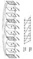
図17は、各ピクチャ間隔で参照ピクチャの最大数を決定するために仮想・ディスプレイ遅延バッファを用いる方法の一例を示す。この例について、許容される参照ピクチャの最大数NRは、4とする。画像符号化装置は、後方参照ピクチャの最大数NBを3に設定する。それゆえに、二つのピクチャの仮想・ディスプレイ遅延バッファが生成される。ディスプレイ・カウンタは、仮想的に表示(出力)されるピクチャの時間的参照番号を記憶及び更新するために用いられる。図中、参照メモリバッファにおける、空白の領域は空きであることを、ピクチャタイプ及び番号が記載されている領域は参照用ピクチャが格納されていることを、斜線でハッチングされた領域は表示用ピクチャが格納されていることを示す。また、仮想・ディスプレイ遅延バッファにおける空白の領域は空きであることを、ピクチャタイプ及び番号が記載されている領域は参照メモリバッファ中の表示用ピクチャに対応する時間的参照番号が格納されていることを、斜線でハッチングされた領域は、表示用ピクチャの格納領域が参照メモリバッファ中に存在しないことを示す。参照メモリバッファにおけるハッチングされた領域に対応した、同数の仮想・ディスプレイ遅延バッファは、表示用ピクチャの時間的参照番号を保持する。
【0176】
図に示すように、ピクチャB2及びB3は、参照ピクチャに対して用いられ、それゆえにそれらは、I0及びP4と一緒に参照メモリ・バッファに記憶されかつディスプレイ・カウンタは、ピクチャB3が符号化された後に更新が開始される。時間T6において、B5は、参照ピクチャとして用いられないが、それは、その時間的参照番号がディスプレイ・カウンタよりも小さいので、仮想・ディスプレイ遅延バッファに更新されることが必要である。それゆえに、そのときにおける仮想・ディスプレイ遅延バッファのフルネスfvは、1でありかつ可能な参照ピクチャの最大数NMaxは、3である。
【0177】
同様に時間T7において、ディスプレイ・カウンタよりも小さいその時間的参照番号によりB5をまだ除去することができないが、B6は、仮想・ディスプレイ遅延バッファに更新されることが必要である。それゆえに、そのときにおけるNMaxは、2である。参照ピクチャI0は、不十分なメモリにより参照メモリ・バッファから除去されなければならない。従って、そのときのB7は、P4及びP8からだけで予測することができる。
【0178】
図18は、ディスプレイ・カウンタが仮想・ディスプレイ遅延バッファを用いて先に増分されるような一例を示す。この例について、NRは、5であるとする。画像符号化装置は、複数の逆方向参照ピクチャの最大数NBを3に設定する。それゆえに、二つのピクチャの仮想・ディスプレイ遅延バッファが生成される。
【0179】
図に示すように、B1、B2、B3及びB4は、参照ピクチャに用いられないが、B7及びB8が用いられる。それゆえに、B1及びB2は、ディスプレイを待つために時間T3で仮想・ディスプレイ遅延バッファに記憶される。仮想・ディスプレイ遅延バッファは、時間T3でフルなので、ディスプレイ・カウンタは、時間T3で更新することを開始する。ディスプレイ・カウンタが、それが更新することを開始できる前に少なくとも仮想・ディスプレイ遅延バッファがフルになるのを待つことが必要な理由は、それが画像復号化装置で発生すると思われるBピクチャのリオーダリングを処理することが必要だからである。
【0180】
図17に示すように、画像復号化装置は、ポスト・デコーダ・バッファとしてその参照ピクチャバッファの一部をときどき用いる。それゆえに参照ピクチャバッファの固定物理メモリ・サイズに基づき、画像復号化装置は、そのある部分が参照ピクチャに用いられかつ残りがポスト・デコーダ・バッファとして用いられるように参照ピクチャバッファを操作する。例えば、時間T3で、参照ピクチャバッファ全体は、参照ピクチャを記憶するために用いられる。他方、時間T7で、参照ピクチャバッファの二つだけがP4及びP8参照ピクチャを記憶するために用いられる。残りは、ポスト・デコーダ・ピクチャB5及びB6を記憶するために用いられる。
【0181】
画像復号化装置側で用いられる参照ピクチャの最大数は、画像符号化装置に対するプロファイル及びレベル定義で規定される。それゆえに、画像符号化装置は、プロファイル及びレベルによって定義された参照ピクチャの最大数まで用いることができる。従って、画像符号化装置は画像復号化装置がこの拘束条件に基づいて動作を行って場合に同様の動作が実現できる(参照ピクチャ数が定義された値を超えない)ように、参照ピクチャの管理を行って符号化を行うことが必要である。
【0182】
同様に、画像復号化装置は、画像符号化装置と同じ数の参照ピクチャを有する。さらに、追加メモリ空間がポスト・デコーダ・バッファに対して必要である。ポスト・デコーダ・ピクチャの最大数は、式(3)によって定義される。
NP=NR−2 (3)
ここで、NPは、ポスト・デコーダ・ピクチャの最大数を表し、NRは、プロファイル及びレベル定義によって定義された参照ピクチャの最大数を表す。
【0183】
それゆえに、プロファイル及びレベルに対して適合する画像復号化装置に対して、このポスト・デコーダ・ピクチャの最大数は、画像復号化装置の設計で考慮しなければならない。このポスト・デコーダ・ピクチャの最大数は、式3から計算することができるか又はプロファイル及びレベル定義で特定することができる。一旦ポスト・デコーダ・ピクチャの最大数がプロファイル及びレベル定義で特定されたならば、値は、式(4)に基づいて後方予測ピクチャの最大数が導出できる。
【0184】
NB=NP+1 (4)
ここで、NBは、参照ピクチャバッファの後方予測ピクチャの最大数を表す。本実施の形態では、それがプロファイルおよびレベル定義に準拠したストリームを復号化できるように画像復号化装置によって要求される最小メモリ要件になる。
【0185】
後方予測の数は、画像復号化装置側で参照ピクチャバッファに追加された追加ポスト・デコーダ・ピクチャの数を削減するために制限することも可能である。例えば、後方予測の最大数が2つに制限された場合には、その場合には1つの追加ポスト・デコーダ・ピクチャだけを参照ピクチャバッファに追加することが必要であり、それは、画像復号化装置側においてポスト・デコーダ・ピクチャに余分な物理メモリ空間の割り当てが行われることを避けることができる。
【0186】
(実施の形態7)
さらに、上記各実施の形態で示した画像符号化方法及び画像復号化方法を実現するためのプログラムを、フレキシブルディスク等の記憶媒体に記録するようにすることにより、上記各実施の形態で示した処理を、独立したコンピュータシステムにおいて簡単に実施することが可能となる。
【0187】
図19は、上記各実施の形態の画像符号化方法及び画像復号化方法を、フレキシブルディスク等の記録媒体に記録されたプログラムを用いて、コンピュータシステムにより実施する場合の説明図である。
図19(b)は、フレキシブルディスクの正面からみた外観、断面構造、及びフレキシブルディスクを示し、図19(a)は、記録媒体本体であるフレキシブルディスクの物理フォーマットの例を示している。フレキシブルディスクFD1はケースF内に内蔵され、該ディスクの表面には、同心円状に外周からは内周に向かって複数のトラックTrが形成され、各トラックは角度方向に16のセクタSeに分割されている。従って、上記プログラムを格納したフレキシブルディスクでは、上記フレキシブルディスクFD1上に割り当てられた領域に、上記プログラムが記録されている。
【0188】
また、図19(c)は、フレキシブルディスクFD1に上記プログラムの記録再生を行うための構成を示す。画像符号化方法及び画像復号化方法を実現する上記プログラムをフレキシブルディスクFD1に記録する場合は、コンピュータシステムCsから上記プログラムをフレキシブルディスクドライブFDDを介して書き込む。また、フレキシブルディスク内のプログラムにより画像符号化方法及び画像復号化方法を実現する上記画像符号化方法及び画像復号化方法をコンピュータシステムCs中に構築する場合は、フレキシブルディスクドライブFDDによりプログラムをフレキシブルディスクから読み出し、コンピュータシステムCsに転送する。
【0189】
なお、上記説明では、記録媒体としてフレキシブルディスクを用いて説明を行ったが、光ディスクを用いても同様に行うことができる。また、記録媒体はこれに限らず、ICカード、ROMカセット等、プログラムを記録できるものであれば同様に実施することができる。
【0190】
(実施の形態8)
さらにここで、上記実施の形態で示した画像符号化方法や画像復号化方法の応用例とそれを用いたシステムを説明する。
図20は、コンテンツ配信サービスを実現するコンテンツ供給システムex100の全体構成を示すブロック図である。通信サービスの提供エリアを所望の大きさに分割し、各セル内にそれぞれ固定無線局である基地局ex107〜ex110が設置されている。
【0191】
このコンテンツ供給システムex100は、例えば、インターネットex101にインターネットサービスプロバイダex102および電話網ex104、および基地局ex107〜ex110を介して、コンピュータex111、PDA(personal digital assistant)ex112、カメラex113、携帯電話ex114、カメラ付きの携帯電話ex115などの各機器が接続される。
【0192】
しかし、コンテンツ供給システムex100は図20のような組合せに限定されず、いずれかを組み合わせて接続するようにしてもよい。また、固定無線局である基地局ex107〜ex110を介さずに、各機器が電話網ex104に直接接続されてもよい。
【0193】
カメラex113はデジタルビデオカメラ等の動画撮影が可能な機器である。また、携帯電話は、PDC(Personal Digital Communications)方式、CDMA(Code Division Multiple Access)方式、W−CDMA(Wideband−Code Division Multiple Access)方式、若しくはGSM(Global System for Mobile Communications)方式の携帯電話機、またはPHS(Personal Handyphone System)等であり、いずれでも構わない。
【0194】
また、ストリーミングサーバex103は、カメラex113から基地局ex109、電話網ex104を通じて接続されており、カメラex113を用いてユーザが送信する符号化処理されたデータに基づいたライブ配信等が可能になる。撮影したデータの符号化処理はカメラex113で行っても、データの送信処理をするサーバ等で行ってもよい。また、カメラ116で撮影した動画データはコンピュータex111を介してストリーミングサーバex103に送信されてもよい。カメラex116はデジタルカメラ等の静止画、動画が撮影可能な機器である。この場合、動画データの符号化はカメラex116で行ってもコンピュータex111で行ってもどちらでもよい。また、符号化処理はコンピュータex111やカメラex116が有するLSIex117において処理することになる。なお、画像符号化・復号化用のソフトウェアをコンピュータex111等で読み取り可能な記録媒体である何らかの蓄積メディア(CD−ROM、フレキシブルディスク、ハードディスクなど)に組み込んでもよい。さらに、カメラ付きの携帯電話ex115で動画データを送信してもよい。このときの動画データは携帯電話ex115が有するLSIで符号化処理されたデータである。
【0195】
このコンテンツ供給システムex100では、ユーザがカメラex113、カメラex116等で撮影しているコンテンツ(例えば、音楽ライブを撮影した映像等)を上記実施の形態同様に符号化処理してストリーミングサーバex103に送信する一方で、ストリーミングサーバex103は要求のあったクライアントに対して上記コンテンツデータをストリーム配信する。クライアントとしては、上記符号化処理されたデータを復号化することが可能な、コンピュータex111、PDAex112、カメラex113、携帯電話ex114等がある。このようにすることでコンテンツ供給システムex100は、符号化されたデータをクライアントにおいて受信して再生することができ、さらにクライアントにおいてリアルタイムで受信して復号化し、再生することにより、個人放送をも実現可能になるシステムである。
【0196】
このシステムを構成する各機器の符号化、復号化には上記各実施の形態で示した画像符号化方法あるいは画像復号化方法を用いるようにすればよい。
その一例として携帯電話について説明する。
図21は、上記実施の形態で説明した画像符号化方法と画像復号化方法を用いた携帯電話ex115を示す図である。携帯電話ex115は、基地局ex110との間で電波を送受信するためのアンテナex201、CCDカメラ等の映像、静止画を撮ることが可能なカメラ部ex203、カメラ部ex203で撮影した映像、アンテナex201で受信した映像等が復号化されたデータを表示する液晶ディスプレイ等の表示部ex202、操作キーex204群から構成される本体部、音声出力をするためのスピーカ等の音声出力部ex208、音声入力をするためのマイク等の音声入力部ex205、撮影した動画もしくは静止画のデータ、受信したメールのデータ、動画のデータもしくは静止画のデータ等、符号化されたデータまたは復号化されたデータを保存するための記録メディアex207、携帯電話ex115に記録メディアex207を装着可能とするためのスロット部ex206を有している。記録メディアex207はSDカード等のプラスチックケース内に電気的に書換えや消去が可能な不揮発性メモリであるEEPROM(Electrically Erasable and Programmable Read Only Memory)の一種であるフラッシュメモリ素子を格納したものである。
【0197】
さらに、携帯電話ex115について図22を用いて説明する。携帯電話ex115は表示部ex202及び操作キーex204を備えた本体部の各部を統括的に制御するようになされた主制御部ex311に対して、電源回路部ex310、操作入力制御部ex304、画像符号化部ex312、カメラインターフェース部ex303、LCD(Liquid Crystal Display)制御部ex302、画像復号化部ex309、多重分離部ex308、記録再生部ex307、変復調回路部ex306及び音声処理部ex305が同期バスex313を介して互いに接続されている。
【0198】
電源回路部ex310は、ユーザの操作により終話及び電源キーがオン状態にされると、バッテリパックから各部に対して電力を供給することによりカメラ付ディジタル携帯電話ex115を動作可能な状態に起動する。
携帯電話ex115は、CPU、ROM及びRAM等でなる主制御部ex311の制御に基づいて、音声通話モード時に音声入力部ex205で集音した音声信号を音声処理部ex305によってディジタル音声データに変換し、これを変復調回路部ex306でスペクトラム拡散処理し、送受信回路部ex301でディジタルアナログ変換処理及び周波数変換処理を施した後にアンテナex201を介して送信する。また携帯電話機ex115は、音声通話モード時にアンテナex201で受信した受信信号を増幅して周波数変換処理及びアナログディジタル変換処理を施し、変復調回路部ex306でスペクトラム逆拡散処理し、音声処理部ex305によってアナログ音声信号に変換した後、これを音声出力部ex208を介して出力する。
【0199】
さらに、データ通信モード時に電子メールを送信する場合、本体部の操作キーex204の操作によって入力された電子メールのテキストデータは操作入力制御部ex304を介して主制御部ex311に送出される。主制御部ex311は、テキストデータを変復調回路部ex306でスペクトラム拡散処理し、送受信回路部ex301でディジタルアナログ変換処理及び周波数変換処理を施した後にアンテナex201を介して基地局ex110へ送信する。
【0200】
データ通信モード時に画像データを送信する場合、カメラ部ex203で撮像された画像データをカメラインターフェース部ex303を介して画像符号化部ex312に供給する。また、画像データを送信しない場合には、カメラ部ex203で撮像した画像データをカメラインターフェース部ex303及びLCD制御部ex302を介して表示部ex202に直接表示することも可能である。
【0201】
画像符号化部ex312は、本願発明で説明した画像符号化装置を備えた構成であり、カメラ部ex203から供給された画像データを上記実施の形態で示した画像符号化装置に用いた符号化方法によって圧縮符号化することにより符号化画像データに変換し、これを多重分離部ex308に送出する。また、このとき同時に携帯電話機ex115は、カメラ部ex203で撮像中に音声入力部ex205で集音した音声を音声処理部ex305を介してディジタルの音声データとして多重分離部ex308に送出する。
【0202】
多重分離部ex308は、画像符号化部ex312から供給された符号化画像データと音声処理部ex305から供給された音声データとを所定の方式で多重化し、その結果得られる多重化データを変復調回路部ex306でスペクトラム拡散処理し、送受信回路部ex301でディジタルアナログ変換処理及び周波数変換処理を施した後にアンテナex201を介して送信する。
【0203】
データ通信モード時にホームページ等にリンクされた動画像ファイルのデータを受信する場合、アンテナex201を介して基地局ex110から受信した受信信号を変復調回路部ex306でスペクトラム逆拡散処理し、その結果得られる多重化データを多重分離部ex308に送出する。
【0204】
また、アンテナex201を介して受信された多重化データを復号化するには、多重分離部ex308は、多重化データを分離することにより画像データの符号化ストリームと音声データの符号化ストリームとに分け、同期バスex313を介して当該符号化画像データを画像復号化部ex309に供給すると共に当該音声データを音声処理部ex305に供給する。
【0205】
次に、画像復号化部ex309は、本願発明で説明した画像復号化装置を備えた構成であり、画像データの符号化ストリームを上記実施の形態で示した符号化方法に対応した復号化方法で復号することにより再生動画像データを生成し、これをLCD制御部ex302を介して表示部ex202に供給し、これにより、例えばホームページにリンクされた動画像ファイルに含まれる動画データが表示される。このとき同時に音声処理部ex305は、音声データをアナログ音声信号に変換した後、これを音声出力部ex208に供給し、これにより、例えばホームページにリンクされた動画像ファイルに含まる音声データが再生される。
【0206】
なお、上記システムの例に限られず、最近は衛星、地上波によるディジタル放送が話題となっており、図23に示すようにディジタル放送用システムにも上記実施の形態の少なくとも画像符号化装置または画像復号化装置のいずれかを組み込むことができる。具体的には、放送局ex409では映像情報の符号化ストリームが電波を介して通信または放送衛星ex410に伝送される。これを受けた放送衛星ex410は、放送用の電波を発信し、この電波を衛星放送受信設備をもつ家庭のアンテナex406で受信し、テレビ(受信機)ex401またはセットトップボックス(STB)ex407などの装置により符号化ストリームを復号化してこれを再生する。また、記録媒体であるCDやDVD等の蓄積メディアex402に記録した符号化ストリームを読み取り、復号化する再生装置ex403にも上記実施の形態で示した画像復号化装置を実装することが可能である。この場合、再生された映像信号はモニタex404に表示される。また、ケーブルテレビ用のケーブルex405または衛星/地上波放送のアンテナex406に接続されたセットトップボックスex407内に画像復号化装置を実装し、これをテレビのモニタex408で再生する構成も考えられる。このときセットトップボックスではなく、テレビ内に画像復号化装置を組み込んでも良い。また、アンテナex411を有する車ex412で衛星ex410からまたは基地局ex107等から信号を受信し、車ex412が有するカーナビゲーションex413等の表示装置に動画を再生することも可能である。
【0207】
更に、画像信号を上記実施の形態で示した画像符号化装置で符号化し、記録媒体に記録することもできる。具体例としては、DVDディスクex421に画像信号を記録するDVDレコーダや、ハードディスクに記録するディスクレコーダなどのレコーダex420がある。更にSDカードex422に記録することもできる。レコーダex420が上記実施の形態で示した画像復号化装置を備えていれば、DVDディスクex421やSDカードex422に記録した画像信号を再生し、モニタex408で表示することができる。
【0208】
なお、カーナビゲーションex413の構成は例えば図22に示す構成のうち、カメラ部ex203とカメラインターフェース部ex303、画像符号化部ex312を除いた構成が考えられ、同様なことがコンピュータex111やテレビ(受信機)ex401等でも考えられる。
【0209】
また、上記携帯電話ex114等の端末は、符号化器・復号化器を両方持つ送受信型の端末の他に、符号化器のみの送信端末、復号化器のみの受信端末の3通りの実装形式が考えられる。
このように、上記実施の形態で示した画像符号化方法あるいは画像復号化方法を上述したいずれの機器・システムに用いることは可能であり、そうすることで、上記実施の形態で説明した効果を得ることができる。
【0210】
また、本発明はかかる上記実施形態に限定されるものではなく、本発明の範囲を逸脱することなく種々の変形又は修正が可能である。
なお、本実施の形態では、本実施では表示すべき順序にピクチャの順序を並べ替えて出力することを表示と表現している。すなわち、復号化画像を表示デバイスに出力するためのプロセスを表示と表現しており、例えば他の記録機器で記録するために復号化画像を出す動作もこの表示の特殊な場合と考えられる。また、表示デバイスが画像メモリを有する場合には、復号化画像を実際の表示時刻よりも早めに表示デバイスに送信することも可能である。
【0211】
【発明の効果】
本発明の画像符号化装置によれば、復号画像が参照用の画像であるかという判定に加えて、出力用の画像であるかという判定も行って、参照用の画像に加えて予測符号化において参照されないが復号されると同時に表示又は出力することができない画像を出力用画像としてピクチャバッファに格納する。画像符号化に際してこのような判定及びピクチャバッファ管理を行い復号動作を検証しているので、復号化装置において出力用の画像を確実にその表示時刻に表示あるいは出力することができる。
【0212】
また、前記ピクチャバッファの一定のサイズの範囲内で、参照用の画像と前記出力用の画像とを、画像を保持している領域を再利用して格納するので、メモリを無駄に消費することなく復号画像ピクチャバッファを必要最小限のサイズとすることができる。
【0213】
さらに、シーケンス毎に前記サイズが一定となるので、シーケンス毎に予測符号化で用いる画像のタイプを柔軟に定めることができる。
また、ピクチャバッファに格納された出力用の画像の領域のうち既に出力済の画像が格納されている領域に、新たな画像を格納する。つまり出力済の画像が格納されている領域を再利用するので、出力済でない復号画像の表示をより確実にすることができる。
【0214】
さらに、出力用の画像のうち表示順で古い画像が格納されている領域には出力済の復号画像が格納されている可能性が高いので、個々の復号画像の表示時刻を正確に判断する構成でなくても、出力済でない復号画像の表示をより確実にすることができる。
【0215】
また、入力画像のサイズが変更されたとき、出力用の復号画像は復号画像ピクチャバッファに残すことができるので、サイズ変更の時点で出力済でない画像を削除することなくできるだけ多く出力することができる。
【図面の簡単な説明】
【図1】ピクチャの予測構造・復号順序と表示順序を示す図を示す。
【図2】ピクチャの予測構造・復号順序と表示順序を示す図を示す。
【図3】本発明の画像符号化方法を実現する画像符号化装置のブロック図(実施の形態1)を示す。
【図4】本発明の参照ピクチャ管理ユニットの動作を示すフローチャート(実施の形態1)を示す。
【図5】(a)(b)(c)はいずれもメモリへのピクチャの保存状態を示す状態図を示す。
【図6】本発明の画像符号化装置の動作を示すフローチャート(実施の形態2)を示す。
【図7】本発明の画像符号化装置の動作を示すフローチャート(実施の形態3)を示す。
【図8】本発明の画像符号化装置の動作を示すフローチャート(実施の形態4)を示す。
【図9】本発明の画像復号化方法を実現する画像復号化装置のブロック図(実施の形態5)を示す。
【図10】本発明における画像復号化装置の動作を示すフローチャート(実施の形態5)を示す。
【図11】本発明における画像復号化装置の他の動作を示すフローチャート(実施の形態5)を示す。
【図12】本発明における画像復号化装置の更に他の動作を示すフローチャート(実施の形態5)を示す。
【図13】本発明における画像復号化装置のまた更に他の動作を示すフローチャート(実施の形態5)を示す。
【図14】画像符号化装置の仮想・ディスプレイ遅延バッファの使用のブロック図を示す。
【図15】符号化における、ポスト・デコーダ・バッファ動作処理における本発明のブロック図を示す。
【図16】復号化における、ポスト・デコーダ・バッファ動作処理における本発明のブロック図を示す。
【図17】参照ピクチャの最大数を制限するために画像符号化装置における仮想・ディスプレイ遅延バッファを用いる一例を示す。
【図18】第1のピクチャをディスプレイするための時間を決定するために仮想・ディスプレイ遅延バッファを用いる一例を示す。
【図19】上記各実施の形態の画像符号化方法及び画像復号化方法をコンピュータシステムにより実現するためのプログラムを格納するための記憶媒体についての説明図(実施の形態7)を示す。
【図20】コンテンツ供給システムの全体構成を示すブロック図(実施の形態8)を示す。
【図21】画像符号化方法及び画像復号化方法を用いた携帯電話の例を示す外観図(実施の形態8)を示す。
【図22】携帯電話のブロック図(実施の形態8)を示す。
【図23】ディジタル放送用システムの例を示す構成図(実施の形態8)を示す。
【図24】ピクチャの予測構造・復号順序と表示順序を示す図を示す。
【図25】ピクチャの予測構造・復号順序と表示順序を示す図を示す。
【図26】従来の画像符号化方法を実現する画像符号化装置のブロック図を示す。
【図27】メモリ管理コマンドMMCOの符号例を示す対応図を示す。
【図28】従来の画像復号化方法を実現する画像復号化装置のブロック図を示す。
【符号の説明】
PicStruct ピクチャ構造決定ユニット
PicSize ピクチャサイズ変更ユニット
PicSizeDet ピクチャサイズ変更検出ユニット
RefPicCtrl 参照ピクチャ管理ユニット
DispPicCtrl 表示ピクチャ管理ユニット
PicMem1、PicMem2 ピクチャメモリ
Add 加算ユニット
Sub 減算ユニット
ME 動き検出ユニット
MC 動き補償ユニット
T 直交変換ユニット
IT 逆直交変換ユニット
Q 量子化ユニット
IQ 逆量子化ユニット
ReOrder 並べ替えユニット
VLC 可変長符号化ユニット
VLD 可変長復号化ユニット
Disp 表示ユニット
SW スイッチ
Sel セレクタ[0001]
TECHNICAL FIELD OF THE INVENTION
The present invention relates to an image encoding method for efficiently compressing a moving image and an image decoding method for correctly decoding and displaying the image.
[0002]
[Prior art]
In recent years, the multimedia era, in which audio, images, and other pixel values are integrated, has been approached. It has been taken up as an object. Generally, multimedia means not only characters, but also figures, sounds, and especially images, etc., that are simultaneously associated with each other. Is an essential condition.
[0003]
However, when the information amount of each of the above information media is estimated as a digital information amount, the information amount per character is 1 to 2 bytes in the case of characters, while 64 Kbits per second in the case of voice (telephone quality). In addition, for a moving image, an information amount of 100 Mbits per second (current television reception quality) or more is required, and it is not realistic to handle the vast amount of information in the above-mentioned information medium in a digital form. For example, a videophone has already been put into practical use by an integrated services digital network (ISDN: Integrated Services Digital Network) having a transmission rate of 64 Kbit / s to 1.5 Mbit / s, but the video of a video camera is directly used by the ISDN. It is impossible to send. Therefore, information compression technology is required. For example, in the case of a videophone, H.264 standardized internationally by ITU-T (International Telecommunication Union Telecommunication Standardization Sector). 261 and H.E. H.263 video compression technology is used. In addition, according to the information compression technology of the MPEG-1 standard, it is possible to store image information together with audio information in a normal music CD (compact disc).
[0004]
Here, MPEG (Moving Picture Experts Group) is an international standard for moving picture signal compression, and MPEG-1 converts moving picture signals up to 1.5 Mbit / s, that is, information of television signals by about 1/100. It is a standard that compresses up to. In addition, since the transmission rate for the MPEG-1 standard is mainly limited to about 1.5 Mbit / s, MPEG-2 standardized to meet the demand for higher image quality (Non-Patent Document 1) In, the moving image signal is compressed to 2 to 15 Mbit / s. Furthermore, at present, the working group (ISO / IEC JTC1 / SC29 / WG11), which has been working on the standardization of MPEG-1 and MPEG-2, has achieved compression ratios exceeding those of MPEG-1 and MPEG-2, and furthermore, on an object-by-object basis. MPEG-4, which enables encoding, decoding, and operation and realizes new functions required in the multimedia age, has been standardized. MPEG-4 was initially aimed at standardizing a low bit rate encoding method, but has now been extended to more general-purpose encoding including high bit rates including interlaced images.
[0005]
Furthermore, in recent years, a new image encoding called JVT as a next-generation encoding of MPEG-4 is being standardized by ITU-T and ISO / IEC jointly.
FIG. 24 is a diagram showing the prediction structure / decoding order and display order of pictures. A picture is a term indicating either a frame or a field, and in this specification, the expression "picture" is used instead of a frame or a field. Also, the term image or screen is synonymous with picture. The pictures hatched in FIG. 24 represent pictures stored in the memory because they are referred to when encoding / decoding other pictures.
[0006]
I0 is an intra-picture coded picture, and P3, P6, and P9 are inter-picture prediction coded pictures (P pictures). According to the JVT standardization scheme, in inter-picture coding, unlike the conventional MPEG-1 / 2/4, an arbitrary picture is selected from a plurality of coded pictures as a reference picture, and a predicted picture is generated from the reference picture. be able to. For example, as for the P9 picture, any one picture can be selected from three pictures I0, P3, and P6, and a predicted image can be generated from the selected picture. This increases the possibility of selecting a more appropriate predicted image than conventional MPEG-1 / 2/4, and improves the compression ratio. B1, B2, B4, B5, B7, and B8 are inter-picture bi-predictive coded pictures (B pictures). Unlike the prediction of inter-picture prediction pictures, a plurality of (two) pictures are selected and the selected picture is selected. To generate and encode a predicted image. In particular, it is known that by performing interpolation prediction using the average value of two temporally preceding and succeeding pictures as a prediction image, the accuracy of the prediction image can be greatly improved and the compression ratio can be greatly improved. Hereinafter, I is assigned to each picture as an intra-coded picture, P is assigned to an inter-picture predictive encoded picture, and B is assigned to an inter-picture bi-predictive encoded picture, and the encoding method of each picture is distinguished.
[0007]
In order to refer to a temporally preceding and succeeding picture in a B picture by predictive coding, a temporally backward picture must be encoded and decoded first. This is called picture rearrangement (reordering) and is often performed from the conventional MPEG-1 / 2/4. Accordingly, the order in which the encoded stream is decoded and displayed (Display Order) is rearranged with respect to the encoding order (Stream Order) as shown in the diagram showing the prediction structure / decoding order and display order of the pictures in FIG. Will be done. Since the B picture in the example of FIG. 24 is displayed at the moment when the stream is decoded, there is no need to store it in a memory or the like when it is not referred to from other images. , Are displayed after decoding the next B-picture, and need to be stored in the memory.
[0008]
Hereinafter, in the drawings showing the prediction structure / decoding order and the display order of pictures, the terms and the meaning of hatched hatching in the pictures are unified with the same meaning as in FIG.
FIG. 25 is a diagram showing the prediction structure / decoding order and display order of other pictures. 24, the difference from FIG. 24 is that
[0009]
FIG. 26 is a block diagram of an image encoding device for realizing a conventional image encoding method. Hereinafter, the operation of the image encoding apparatus that realizes the conventional image encoding method of FIG. 26 will be described.
The picture structure determination unit PicStruct determines the coding type (I picture, P picture, B picture) of each picture, and indicates to the reference picture management unit RefPicCtrl the coding type and pictures that can be referred to in the coding. Is notified to the reordering unit ReOrder. The rearrangement unit ReOrder rearranges the order of the input pictures PicIn into the encoding order, and outputs the rearranged pictures to the motion estimation unit ME and the subtraction unit Sub. The motion detection unit ME refers to the picture stored in the picture memory PicMem1 to derive an appropriate reference picture and a motion vector MV indicating the pixel position, and obtains a variable-length coding unit VLC, a picture memory PicMem1, and a motion compensation unit MC. To send to. The picture memory PicMem1 outputs pixels of the reference picture corresponding to the motion vector MV to the motion compensation unit MC, and the motion compensation unit MC generates a predicted image from the pixels of the reference picture obtained from the picture memory PicMem1 and the motion vector MV.
[0010]
The subtraction unit Sub calculates the difference between the reordered picture and the predicted image in the reordering unit ReOrder, converts the difference into a frequency coefficient in the orthogonal transform unit T, further quantizes the frequency coefficient in the quantization unit Q, and performs quantization. The value is Coef.
The inverse quantization unit IQ inversely quantizes the quantized value Coef to restore it to a frequency coefficient, and further performs an inverse frequency transform from the frequency coefficient to a pixel difference value in an inverse orthogonal transform unit IT. The addition unit Add adds the predicted image to the pixel difference value to obtain a decoded image.
[0011]
The reference picture management unit RefPicCtrl stores a decoded image to be stored in the picture memory PicMem1 for reference as a reference picture or a decoded image to be released from the picture memory PicMem1 (not to be referred to as a reference picture hereinafter) according to the coding type of the picture. It is determined whether or not there is, and the operation is notified as a memory management command MMCO.
[0012]
The switch SW is turned on when the storage of the decoded image is instructed by the memory management command MMCO, and the decoded image is stored in the picture memory PicMem1 as a reference picture. Further, when a decoded image to be released is designated from the picture memory PicMem1 by the memory management command MMCO, the picture memory PicMem1 can release the area storing the decoded image and store another decoded image in that area. To
[0013]
The variable length coding unit VLC codes the quantized value Coef, the motion vector MV, and the memory management command MMCO, and outputs a coded stream Str.
Although an example in which the frequency conversion and the quantization are performed is shown as the coding, the coding without the frequency conversion and the quantization (DPCM, ADPCM, linear prediction coding, or the like) may be used. Further, coding in which frequency conversion and quantization are integrated, or coding without quantization after frequency conversion, such as bit plane coding, may be used.
[0014]
FIG. 27 is a code example of the memory management command MMCO. At the beginning of encoding / decoding or at the beginning of a GOP, in order to initialize the picture memory, the variable length encoding unit VLC encodes “000” which means that all memory is released. Further, when storing the decoded image in the picture memory, the variable length coding unit VLC codes “01”. When releasing a picture stored in the picture memory, the picture number to be released must be indicated, so the variable length coding unit VLC encodes the picture number to be released next to '001'. When releasing a plurality of pictures at the same time, it is necessary to encode the release command a plurality of times. In addition to the command for releasing the picture, the picture may be stored. Therefore, the variable length coding unit VLC continuously codes the plurality of memory management commands MMCO, and finally codes “1” indicating that the memory management command MMCO is completed. As described above, the memory management command MMCO is encoded into the encoded stream Str.
[0015]
FIG. 28 is a block diagram of an image decoding apparatus that realizes a conventional image decoding method. In the figure, devices that perform the same operations as those in the block diagram of the image encoding apparatus that realizes the conventional image encoding method of FIG.
The variable length decoding unit VLD decodes the encoded stream Str and outputs a memory management command MMCO, a motion vector MV, and a quantized value Coef. The picture time Time is a signal that is input from the outside and specifies a picture to be displayed. If the picture to be displayed is the decoded picture, the output of the addition unit Add is selected by the selector Sel and sent to the display unit Disp. If the picture to be displayed is a picture stored in the picture memory PicMem1, it is read from the picture memory PicMem1, selected by the lector Sel, and sent to the display unit Disp.
[0016]
As described above, the picture memory PicMem1 outputs a pixel corresponding to the motion vector MV to the motion compensation unit MC, and the motion compensation unit MC generates a predicted image from the pixel obtained from the picture memory PicMem1 and the motion vector MV.
Further, the inverse quantization unit IQ inversely quantizes the quantized value Coef to restore the frequency coefficient, and further performs inverse frequency conversion from the frequency coefficient to the pixel difference value in the inverse orthogonal transform unit IT. The addition unit Add adds the prediction image to the pixel difference value to obtain a decoded image.
[0017]
Also, when a decoded image to be released in the picture memory PicMem1 is specified by the memory management command MMCO, the picture memory PicMem1 releases the area storing the decoded image and stores another decoded image in the area. enable.
Although an example has been shown in which decoding involves inverse frequency transform and inverse quantization, decoding without inverse frequency transform and inverse quantization (DPCM, ADPCM, linear predictive coding, etc.) may be used. In addition, decoding in which inverse frequency conversion and inverse quantization are integrated, or decoding without inverse quantization after frequency conversion, such as bit plane coding, may be used.
[0018]
With the above-described image decoding apparatus that realizes the conventional image decoding method of FIG. 28, the combination of the conventional picture coding types shown in FIGS. 24 and 25 is changed to an image that realizes the conventional image coding method of FIG. It is clear that the encoded stream Str encoded by the encoding device can be correctly decoded.
[0019]
[Non-patent document 1]
"ISO / IEC 13818-2, Information technology-Generic coding of moving pictures and associated audio information: Video" (May 15, 1996)
[0020]
[Problems to be solved by the invention]
By the way, a more flexible combination was considered as a picture coding type.
FIG. 1 is a diagram showing a prediction structure, decoding order, and display order of a picture which are not present in the related art. In FIG. 1, the prediction structure of the B picture differs before and after
[0021]
Now, pictures 5 and 6 are B pictures that are not stored because they are not referred to in predictive coding. However, unlike the case of FIG. 24, at the time of decoding, it is the display time of another picture, and the display time is not yet reached. That is, picture P4 must be displayed at the time of decoding picture B5, and picture B5 must be displayed at the time of decoding picture B6. On the other hand, since the pictures B5 and B6 are not stored, the pictures B5 and B6 cannot be output from the picture memory at the display time. Therefore, pictures that are not referred to in the predictive coding are not stored in the picture memory, so that the pictures B5 and B6 cannot be decoded and displayed by the conventional coding / decoding method. That is, as in the example shown in FIG. 24, when pictures that are not referred to in predictive coding are not stored,
[0022]
As described above, if a more flexible combination is considered as the picture coding type, there is a problem that a picture that cannot be decoded and displayed is generated. If a picture memory is separately added for display and pictures not stored in the picture memory PicMem1 are stored in another picture memory for display, display becomes possible. In this case, a large picture memory is stored in another picture memory. The disadvantage is that extra memory is required.
[0023]
Further, even if another picture memory for display is introduced, a new problem occurs in reproduction from the middle of the stream. FIG. 2 is a diagram showing the prediction structure / decoding order and display order of pictures. 25, the difference from FIG. 25 is that the prediction structure before and after
[0024]
By the way, in order to play back from the middle of the stream, it is necessary to guarantee that the playback image matches between the encoding device and the decoding device even at the time of playback from the middle of the stream. Is an easy way to initialize. However, since the
[0025]
In view of the above, an object of the present invention is to prevent the occurrence of a picture that cannot be decoded and displayed while taking into account the amount of memory required for encoding or decoding an image.
[0026]
[Means for Solving the Problems]
In order to achieve the above object, an image encoding apparatus according to the present invention includes an image encoding method for predictively encoding an input image with reference to an image held in a picture buffer and decoding the encoded input image. It is determined whether or not the decoded image is a reference image and an output image that needs to be held until a display time, and the reference image and the output are determined based on the determination result. Is stored in the picture buffer.
[0027]
Here, the image encoding method includes a first determining step of determining whether the decoded image is a reference image, and holding the decoded image not for reference and until the display time. A second determination step of determining whether or not the image is a necessary output image; and an image determined as a reference image in the first determination step is stored in the picture buffer. A management step of managing a picture buffer so that an image determined to be an image for output is held in the picture buffer may be provided.
[0028]
According to this configuration, in addition to determining whether the decoded image is an image for reference, it is also determined whether or not the decoded image is an image for output. At the same time, an image that cannot be displayed or output is stored in the picture buffer as an output image. Since such determination and picture buffer management are performed at the time of image encoding to verify the decoding operation, the decoding device can reliably display or output the output image at the display time.
[0029]
Here, the picture buffer has a fixed size, and the image encoding method further includes a third determining step of determining whether or not the reference image held in the picture buffer has been referred to. And a fourth determination step of determining whether or not the output image held in the picture buffer has been output. In the management step, each determination in the third and fourth determination steps Based on the result, a configuration may be adopted in which the area holding the image in the picture buffer within the fixed size range is reused.
[0030]
According to this configuration, in the management step, the reference image and the output image are stored by reusing the area holding the image within the fixed size range of the picture buffer. Thus, the size of the decoded image picture buffer can be reduced to a necessary minimum without wasting memory.
[0031]
Further, the image encoding method may include an encoding step of encoding, for each sequence including a plurality of encoded images, information indicating the size, which is constant in encoding the sequence.
According to this configuration, since the size is constant for each sequence, the type of image used for predictive coding can be flexibly determined for each sequence.
[0032]
Further, in the management step, when there is no area in the picture buffer where a new image can be stored, an area holding an output image determined to be output in the fourth determination step. Alternatively, any one of the image determined as the reference image in the first determination step and the image determined as the reference image in the second determination step may be stored.
[0033]
According to this configuration, a new image is stored in an area of an image for output stored in the picture buffer in which an already output image is stored. That is, since the area in which the output image is stored is reused, it is possible to more reliably display the decoded image that has not been output.
[0034]
Further, in the managing step, if there is no area in the picture buffer in which a new image can be stored, the area holding the oldest image in the display order among the output images stored in the picture buffer is used. Alternatively, a configuration may be employed in which one of the image determined as the reference image in the first determination step and the image determined as the output image in the second determination step is held.
[0035]
According to this configuration, the output decoded image is likely to be stored in the area where the oldest image is stored in the display order among the output images, so that the display time of each decoded image can be accurately set. , It is possible to more reliably display a decoded image that has not been output.
[0036]
Further, the image encoding method further includes, when the size of the input image is changed in the middle of the sequence including the plurality of encoded images, in the area holding the output image, In addition, a configuration may be provided that includes an opening step of opening an area other than an area holding an image in which all or part of the image has not been changed after storage.
[0037]
According to this configuration, when the size is changed, the decoded image for output can be left in the decoded image picture buffer. Therefore, it is possible to output as much as possible without deleting the image that has not been output at the time of the size change. it can.
As described above, according to the present invention, a picture that could not be correctly displayed in the past can be displayed by effectively utilizing an open memory area without having extra memory, and its practical value Is expensive.
[0038]
The image decoding method, the image encoding device, the image decoding device, and the program according to the present invention also have the same configuration, operation, and effect as described above.
Further, the image encoding method or the image decoding method of the present invention can have any one of the following configurations (1) to (16).
[0039]
(1) An image encoding method for predictively encoding an image signal with reference to a decoded image stored in a memory and generating a predicted image by referring to the decoded image from a memory Encoding the difference between the predicted image and the image signal into an encoded stream, and decoding the difference between the encoded predicted image and the image signal and adding the predicted image to form a decoded image. Storing a predetermined decoded image in the memory, and including, in the encoded stream, instruction information indicating whether or not the entire area of the memory is released to be reusable. Image encoding method.
[0040]
(2) An image encoding method for predictively encoding an image signal with reference to a decoded image, wherein a predicted image is generated by referring to a decoded image from a memory, and the predicted image and the predicted image The difference between the image signals is encoded into an encoded stream, the difference between the encoded predicted image and the image signal is decoded, and the predicted image is added to obtain a decoded image, which is referred to for generating a predicted image. An image encoding method for storing the decoded image in the memory for an image and an image that cannot be displayed immediately.
[0041]
(3) An image encoding method for predictively encoding an image signal with reference to a decoded image, wherein a predicted image is generated by referring to a decoded image from a memory, and the predicted image and the predicted image The difference between the image signals is encoded into an encoded stream, the difference between the encoded predicted image and the image signal is decoded, and the predicted image is added to form a decoded image.The decoded image is stored in the memory. Image encoding method for releasing an unnecessary image from the memory and storing the decoded image in the memory in the area where the displayed image is stored in the opened area in the memory. .
[0042]
(4) An image decoding method for predictively decoding an encoded stream with reference to a decoded image that has been decoded and stored in a memory,
A predicted image is generated by referring to the decoded image from the memory, and the predicted image is added to an image signal obtained by decoding the encoded stream to obtain a decoded image, and a predetermined decoded image is stored in the memory. Steps to
A processing step of performing processing based on the information indicated by the instruction information, based on instruction information indicating whether or not the entire area of the memory obtained by decoding the encoded stream is to be released and reused.
An image decoding method comprising:
[0043]
(5) An image decoding method for predicting and decoding an encoded stream with reference to a decoded image, wherein the decoded image is referred to from a memory to generate a predicted image, and the encoded stream is decoded. Adding the predicted image to a decoded image, storing the decoded image in the memory or releasing an unnecessary image from the memory, and opening the decoded image in the memory when storing the decoded image in the memory. An image decoding method for storing in a region where a displayed image has been stored in the displayed region.
[0044]
(6) An image coding method for predictively coding an image signal with reference to a decoded image, wherein a predicted image is generated by referring to a decoded image from a memory, and the predicted image and the predicted image The difference between the image signals is encoded into an encoded stream, the difference between the encoded predicted image and the image signal is decoded, and the predicted image is added to form a decoded image.The decoded image is stored in the memory. Image encoding that releases an unnecessary image from the memory and stores the decoded image in the memory in the area where the image at the oldest time is stored in the open area in the memory. Method.
[0045]
(7) An image decoding method for predicting and decoding an encoded stream by referring to a decoded image, wherein a predicted image is generated by referring to the decoded image from a memory, and the encoded stream is decoded. Adding the predicted image to a decoded image, storing the decoded image in the memory or releasing an unnecessary image from the memory, and opening the decoded image in the memory when storing the decoded image in the memory. An image decoding method for storing an image at the oldest time in an area in which an image at the oldest time is stored.
[0046]
(8) An image encoding method for predictively encoding an image signal with reference to a decoded image, wherein a predicted image is generated by referring to a decoded image from a memory, and the predicted image and the predicted image The difference between the image signals is encoded into an encoded stream, the difference between the encoded predicted image and the image signal is decoded, and the predicted image is added to form a decoded image.The decoded image is stored in the memory. An image encoding method for releasing an unnecessary image from the memory and storing the decoded image in the memory in a first storable area opened in the memory.
[0047]
(9) An image decoding method for predicting and decoding an encoded stream with reference to a decoded image, wherein the decoded image is referred to from a memory to generate a predicted image, and the encoded stream is decoded. The predicted image is added to obtain a decoded image, and the decoded image is stored in the memory or an unnecessary image is released from the memory, and when the decoded image is stored in the memory, the decoded image is first stored in the memory. Image decoding method for storing in a storable area opened to the public.
[0048]
(10) An image coding device that predictively codes an image signal with reference to a decoded image, wherein the prediction unit generates a prediction image by referring to the decoded image from a memory, Encoding means for encoding the difference between the predicted image and the image signal as an encoded stream, decoding means for decoding the encoded difference between the predicted image and the image signal, and the decoding means Adding means for adding the decoded difference between the predicted image and the image signal and the predicted image; and a reference for determining that an image to be referred to for generating the predicted image and an image that cannot be displayed immediately are stored in the memory. An image coding apparatus comprising: an image management unit; and a memory unit that stores the addition result of the addition unit in the memory based on a determination of the reference image management unit.
[0049]
(11) An image encoding device that predictively encodes an image signal with reference to a decoded image, comprising: a prediction unit configured to generate a predicted image by referring to a decoded image from a memory; Encoding means for encoding the difference between the predicted image and the image signal as an encoded stream, decoding means for decoding the encoded difference between the predicted image and the image signal, and the decoding means Adding means for adding the difference between the decoded predicted image and the image signal and the predicted image; reference image managing means for storing the addition result of the adding means in a memory or determining to release an unnecessary image from the memory And an image in which the addition result of the addition means is an open area in the memory based on the determination of the reference image management means and which has been output to the outside as a decoded image by the decoding device. Territory Image encoding apparatus having a memory means for storing the.
[0050]
(12) An image decoding device that predictively decodes an encoded stream with reference to a decoded image, the decoding unit decoding the encoded stream, and the decoded image is referred to from a memory. Prediction means for generating a prediction image; addition means for adding the difference between the prediction image and the image signal decoded by the decoding means and the prediction image; storing the addition result of the addition means in a memory or unnecessary A reference image management unit that determines to release a proper image from the memory, and based on the determination of the reference image management unit, outputs the addition result of the addition unit to an external area as an open area in the memory and a decoded image. An image decoding device comprising a memory means for storing an output image in an area where the output image is stored.
[0051]
(13) An image encoding device that predictively encodes an image signal with reference to a decoded image, wherein the prediction unit generates a prediction image by referring to the decoded image from a memory, Encoding means for encoding the difference between the predicted image and the image signal as an encoded stream, decoding means for decoding the encoded difference between the predicted image and the image signal, and the decoding means Adding means for adding the difference between the decoded predicted image and the image signal and the predicted image; reference image managing means for storing the addition result of the adding means in a memory or determining to release an unnecessary image from the memory An image having memory means for storing the addition result of the addition means in an open area in the memory where the image with the oldest time is stored based on the judgment of the reference image management means Goka apparatus.
[0052]
(14) An image decoding device that predictively decodes an encoded stream with reference to a decoded image, wherein the decoding unit decodes the encoded stream, and the decoded image is referred to from a memory. Prediction means for generating a prediction image; addition means for adding the difference between the prediction image and the image signal decoded by the decoding means and the prediction image; storing the addition result of the addition means in a memory or unnecessary A reference image management means for determining that a new image is to be released from the memory; and storing an addition result of the addition means based on the determination of the reference image management means in an open area in the memory and having the oldest time. An image decoding device comprising a memory means for storing data in an area where the image decoding has been performed.
[0053]
(15) An image encoding device that predictively encodes an image signal with reference to a decoded image, wherein the prediction unit generates a prediction image by referring to the decoded image from a memory, and the prediction unit performs prediction with the prediction unit. Encoding means for encoding the difference between the predicted image and the image signal as an encoded stream, decoding means for decoding the encoded difference between the predicted image and the image signal, and the decoding means Adding means for adding the difference between the decoded predicted image and the image signal and the predicted image; reference image managing means for storing the addition result of the adding means in a memory or determining to release an unnecessary image from the memory An image encoding apparatus comprising: memory means for storing the addition result of the addition means in an open area in a memory in an area in which the order of release is earlier based on a determination of the reference image management means.
[0054]
(16) An image decoding device that predictively decodes an encoded stream with reference to a decoded image, wherein the decoding unit decodes the encoded stream, and the decoded image is referred to from a memory. Prediction means for generating a prediction image; addition means for adding the difference between the prediction image and the image signal decoded by the decoding means and the prediction image; storing the addition result of the addition means in a memory or unnecessary A reference image management unit that determines to release a proper image from the memory, and based on the determination of the reference image management unit, adds the addition result of the addition unit to an open area in the memory and an area where the order of release is earlier. An image decoding device comprising a memory means for storing.
[0055]
Further, the storage medium storing a program for causing a computer to execute the image encoding method and the image decoding method of the present invention may be any of the following (17) to (23).
[0056]
(17) The program is an image encoding method for causing a computer to predictively encode an image signal with reference to a decoded image, wherein the program generates a predicted image by referring to the decoded image from a memory, Encoding the difference between the predicted image and the image signal into an encoded stream, decoding the difference between the encoded predicted image and the image signal, adding the predicted image to form a decoded image, and generating a predicted image. A storage medium for causing an image encoding method for storing the decoded image in the memory to be performed on an image referred to for the image and an image that cannot be displayed immediately.
[0057]
(18) The above program is an image encoding method for causing a computer to predictively encode an image signal with reference to a decoded image, wherein the program generates a predicted image by referring to a decoded image from a memory, Encoding the difference between the predicted image and the image signal into an encoded stream, decoding the difference between the encoded predicted image and the image signal, adding the predicted image to form a decoded image, When the image stored in the memory or the unnecessary image is released from the memory and the decoded image is stored in the memory, the image displayed in the opened area in the memory is stored in the area where the displayed image is stored. A storage medium for causing a stored image encoding method to be performed.
[0058]
(19) The above program is an image decoding method for causing a computer to predictively decode an encoded stream with reference to a decoded image, and generates a predicted image by referring to the decoded image from a memory. When decoding a coded stream and adding the predicted image to obtain a decoded image, storing the decoded image in the memory or releasing an unnecessary image from the memory, and storing the decoded image in the memory. A storage medium for performing an image decoding method for storing an image that has been displayed in an open area in the memory and in which the displayed image has been stored.
[0059]
(20) The program is an image encoding method for causing a computer to predictively encode an image signal with reference to a decoded image, wherein the program generates a predicted image by referring to a decoded image from a memory, Encoding the difference between the predicted image and the image signal into an encoded stream, decoding the difference between the encoded predicted image and the image signal, adding the predicted image to form a decoded image, Is stored in the memory or an unnecessary image is released from the memory, and when the decoded image is stored in the memory, the area where the image at the oldest time is stored in the released area in the memory. A storage medium for performing an image encoding method stored in a storage medium.
[0060]
(21) The above-mentioned program is an image decoding method for causing a computer to predictively decode an encoded stream with reference to a decoded image, and generates a predicted image by referring to the decoded image from a memory. When decoding a coded stream and adding the predicted image to obtain a decoded image, storing the decoded image in the memory or releasing an unnecessary image from the memory, and storing the decoded image in the memory. A storage medium for performing an image decoding method of storing an image at the oldest time in an open area in the memory where an image at the oldest time is stored.
[0061]
(22) The above program is an image encoding method for causing a computer to predictively encode an image signal with reference to a decoded image, wherein the program generates a predicted image by referring to the decoded image from a memory, Encoding the difference between the predicted image and the image signal into an encoded stream, decoding the difference between the encoded predicted image and the image signal, adding the predicted image to form a decoded image, An image encoding method for storing an unnecessary image in the memory or releasing an unnecessary image from the memory, and storing the decoded image in the memory in a storable area opened first in the memory. And a storage medium.
[0062]
(23) The above program is an image decoding method for causing a computer to predictively decode an encoded stream with reference to a decoded image, and generates a predicted image by referring to the decoded image from a memory. When decoding a coded stream and adding the predicted image to obtain a decoded image, storing the decoded image in the memory or releasing an unnecessary image from the memory, and storing the decoded image in the memory. A storage medium for performing an image decoding method of storing an image in a storable area opened first in the memory.
[0063]
Further, in the image encoding apparatus of the present invention, a method of defining a memory constraint condition for a stream and an image decoding apparatus and encoding a video may be any of the following (A1) to (A26).
[0064]
(A1) An image coding method for defining a memory constraint condition for a stream and an image decoding device, wherein the step of determining the maximum number of reference pictures that can be used and the maximum number of backward prediction reference pictures are set. Placing the maximum number of backward predicted reference pictures in the header of the stream; generating a virtual display delay buffer; generating a display counter; and providing sufficient storage space for the reference pictures. An image encoding method, comprising: allocating; and encoding the video. Here, the virtual / display delay buffer is a virtual buffer corresponding to each display picture to be stored in the display area secured in the memory in the image encoding device, and outputs the display picture. Information indicating the order (picture order number, etc.) is held. The display counter stores and updates the picture sequence number of the picture to be virtually output to the display. The sufficient storage space refers to an area for storing reference pictures and display pictures.
[0065]
(A2) The image encoding method according to (A1), wherein the maximum number of reference pictures is determined according to a level value indicating a capability of a decoder.
[0066]
(A3) The image encoding method according to (A1) or (A2), wherein the maximum number of backward prediction reference pictures is smaller than the maximum number of reference pictures.
[0067]
(A4) The image encoding method according to (A1), (A2) or (A3), wherein the backward prediction of the entire stream is limited by the maximum number of backward prediction reference pictures.
[0068]
(A5) The image encoding method according to (A1), wherein the size of the virtual / display delay buffer is obtained by subtracting 1 from the maximum number of backward prediction reference pictures.
[0069]
(A6) The image encoding method according to (A1) or (A5), wherein the physical memory of the virtual / display delay buffer includes only display order information of pictures.
[0070]
(A7) The image encoding method according to (A1), wherein the display counter is used to store display order information of pictures to be removed from a virtual display delay buffer.
[0071]
(A8) In the image encoding method, a step of predicting an encoding target picture using an available reference picture, a step of encoding the encoding target picture, and the encoded picture is used for prediction. Determining whether or not, decoding the encoded picture; storing the decoded picture in the reference picture buffer; updating the virtual display delay buffer; Updating the display counter; (A1).
[0072]
(A9) The image encoding method according to (A1) or (A8), wherein the prediction of a picture can use one or more reference pictures when the picture is predictively encoded.
[0073]
(A10) The image encoding method according to (A1) or (A8), wherein the reference picture can be used only when the reference picture buffer satisfies a memory constraint condition.
[0074]
(A11) The image encoding method according to (A1) or (A8), wherein the reference picture is decoded when the current picture is used as a reference picture.
[0075]
(A12) storing the decoded picture; determining a memory constraint condition of the number of reference pictures for a next picture; removing unused reference pictures from the reference picture buffer; Adding the picture to the reference picture buffer. (A1), (A8) or (A10).
[0076]
(A13) The maximum number of reference pictures for the next picture is equal to the maximum number of reference pictures for the stream minus the number of pictures in the virtual / display delay buffer. (A1), (A8), (A10) Or the image coding method according to (A12).
[0077]
(A14) The display order information of the unused reference picture for the display is moved to the virtual / display delay buffer when the display order information for the display is larger than the value of the display counter. (A1), (A8) ), (A10) or (A12).
[0078]
(A15) The image according to (A1) or (A8), wherein the virtual display delay buffer stores the temporal information of the picture when the display order information is larger than the value of the display counter. Encoding method.
[0079]
(A16) The virtual / display delay buffer removes the display order information of the picture when the display order information is equal to or less than the value of the display counter, (A1), (A8), or (A15). ).
[0080]
(A17) The number of pictures in the virtual / display delay buffer is defined by (A1), (A8), (A10), (A10), which is defined by the total number of display order information of pictures present in the virtual / display delay buffer. The image encoding method according to (A12) or (A13).
[0081]
(A18) The display order information of the display counter starts updating when the virtual display delay buffer is full or when the number of coded pictures is equal to the maximum number of reference pictures. (A1) ) Or (A8).
[0082]
(A19) The display order information of the display counter is updated based on the display order information of each picture encoded after the display counter starts updating, (A1), (A8), or (A18). ).
[0083]
(A20) The image decoding device for the image encoding device includes: determining a maximum post-decoder buffer size from a stream header; determining a minimum number of required reference pictures; The image encoding method according to (A1), comprising: allocating a sufficient physical memory space to the stream, decoding the stream, and outputting the stream.
[0084]
(A21) The image encoding method according to (A1) or (A20), wherein the maximum post-decoder buffer size is a maximum number of backward reference pictures set by the image encoding device.
[0085]
(A22) The image encoding method according to (A1) or (A20), wherein the minimum number of necessary reference pictures is fixed with respect to a capability level of the image decoding device capable of decoding the same stream.
[0086]
(A23) The image code according to (A1) or (A20), wherein the physical memory space allocated by the image decoding device can be used to store both a reference picture and a post-decoder picture. Method.
[0087]
(A24) The image encoding method according to (A1) or (A20), wherein the sum of both the reference picture and the post-decoder picture does not exceed the allocated physical memory space.
[0088]
(A25) The decoding is performed when the number of decoded pictures is equal to the maximum post-decoder buffer size minus one, or when the total number of decoded pictures is the reference picture. The image encoding method according to (A1) or (A20), wherein the first decoded picture is output earlier when the number is equal to the minimum number.
[0089]
(A26) The image encoding method according to (A1) or (A20), wherein the decoded picture is removed from the post-decoder buffer once it has been sent for output.
[0090]
Further, the method of decoding the stream in the image decoding device of the present invention based on the stream and the memory constraint for the image decoding device may be any one of the following (A27) to (A37).
[0091]
(A27) A method for decoding a stream based on a memory constraint for a stream and an image decoding apparatus, the method comprising: determining a maximum number of reference pictures used for the stream; Determining; calculating the minimum size of the post decoder buffer; allocating sufficient physical memory space for the reference picture buffer; and allocating sufficient physical memory space for the post decoder buffer. Allocating, decoding the stream, storing the decoded picture in a reference picture buffer, storing the decoded picture in a post decoder buffer, and outputting the decoded picture. And an image decoding method. Here, the post-decoder buffer refers to a display area in a reference picture memory in the image decoding device.
[0092]
(A28) The image decoding method according to (A27), wherein the maximum number of reference pictures is fixed for the image decoding device according to a level of the ability to decode the stream.
[0093]
(A29) The image decoding method according to (A27), wherein the maximum possible number of backward prediction reference pictures is defined by a number obtained by subtracting 1 from the maximum number of reference pictures.
[0094]
(A30) The image decoding method according to (A27), wherein the minimum size of the post-decoder buffer is defined as a value obtained by subtracting 1 from the maximum possible number of backward prediction reference pictures.
[0095]
(A31) The image decoding method according to (A27) or (A30), wherein the minimum size of the post-decoder buffer is obtained from a stream.
[0096]
(A32) The image decoding method according to (A27) or (A31), wherein the maximum possible number of backward prediction reference pictures is defined by a number obtained by adding 1 to the minimum size of the post-decoder buffer.
[0097]
(A33) The image decoding method according to (A27), wherein the minimum size of the reference picture buffer is defined as the maximum number of reference pictures.
[0098]
(A34) The image decoding method according to (A27) or (A33), wherein the reference picture buffer is used only for storing a reference picture.
[0099]
(A35) The image decoding method according to (A27), (A30) or (A31), wherein the post-decoder buffer is used to store a non-reference picture.
[0100]
(A36) The image decoding method according to (A27), (A32) or (A33), wherein the reference picture is removed from the reference picture buffer when it is determined to be a non-reference picture.
[0101]
(A37) The image decoding according to (A27), (A30), (A31) or (A35), wherein the picture in the post decoder buffer is removed from the post decoder buffer when it is output. Method.
[0102]
According to the above configuration, by operating both the stream and the image decoding device under the same memory constraint condition, it is possible to guarantee that the stream can be correctly decoded. Otherwise, the image decoding apparatus may not be able to secure enough memory space to decode the stream during the decoding process.
[0103]
BEST MODE FOR CARRYING OUT THE INVENTION
Hereinafter, embodiments of the present invention will be described with reference to the drawings.
[0104]
(Embodiment 1)
FIG. 3 is a block diagram of an image encoding device for realizing the image encoding method of the present invention. In the figure, devices that perform the same operations as those in the block diagram of the image encoding apparatus that realizes the conventional image encoding method of FIG.
26 is different from the block diagram of the image encoding apparatus which realizes the conventional image encoding method in FIG. 26 in that a display picture management unit DispPicCtrl is added in FIG. Is output to the picture memory PicMem2.
[0105]
In addition, the
[0106]
Since the operation of the picture memory PicMem2 is almost the same as that of the picture memory PicMem1, only the different operation will be described.
The display picture management unit DispPicCtrl acquires the picture time Time, and determines whether or not a picture that is not originally stored because it is not referred to can be immediately displayed (whether it is necessary to store the picture up to the display time in the picture memory). The picture time Time is a signal that is input from the outside and specifies a picture to be displayed. The picture time may be obtained, for example, from time information output by a system for transmitting a picture over a transmission path such as a packet, or may be obtained from a format for multiplexing a video stream and an audio stream. It may be obtained from the time information, or may be obtained from the time information in the format of the video stream. In addition, these may be either absolute times in which the time can be determined for each picture, or relative times in which the time before or after the time can be determined between the pictures. Furthermore, since the display interval of the pictures is usually fixed, the display order of the pictures may be considered as the time.
[0107]
The case where the display is possible immediately is a case where the picture obtained by the addition by the adder Add matches the picture to be displayed designated by the picture time Time. In this case, there is no picture in the picture memory PicMem2 that should not be displayed and should be displayed before the picture input for encoding. If the image cannot be displayed immediately, the display picture management unit DispPicCtrl issues an instruction to the reference picture management unit RefPicCtrl so that even an image that is not referenced is stored in the picture memory PicMem2. As a result, a picture that is not immediately displayed is always stored in the picture memory PicMem2 regardless of the presence or absence of reference, and the decoding device can display the picture from the picture memory PicMem2.
[0108]
FIG. 4 is a flowchart of the operation of the reference picture management unit RefPicCtrl in the present invention.
It is determined whether the decoded image (picture) should be saved in order to be referred to as a predicted image (Step 10). If it is referenced, the process proceeds to Step 12, otherwise, the process proceeds to Step 11.
[0109]
In Step 11, it is determined whether or not the decoded image can be displayed immediately. Immediately displayable means that the image can be displayed as it is at the time of decoding (for example,
[0110]
In Step 12, a storable area is acquired from the picture memory PicMem2, and an instruction is issued by the memory management command MMCO to save the decoded image in the area of the picture memory PicMem2 acquired in Step 13.
As described above, the picture that is not immediately displayed can be stored in the picture memory PicMem2, and the picture can be displayed from the picture memory PicMem2 when the display time comes. Further, a picture that needs to be stored for display can be stored in a reference picture memory without requiring an extra picture memory for display.
[0111]
The above-described picture memory PicMem2 has a reference area in which a reference picture referred to for generating a predicted image is stored, and a display area in which a display picture is stored.
By the way, the picture size can be changed for each GOP (group of pictures). This change in the picture size is performed only when all the reference areas in the memory in which unnecessary reference pictures are stored are released (to be reusable).
[0112]
However, when the picture size is changed as described above, as described above, the undisplayed display picture is stored in the memory area, and how to handle the undisplayed display picture is described. (Whether to erase or save until displayed) needs to be clearly determined.
[0113]
Here, the storage state of the picture in the memory when the picture size is changed will be described step by step.
FIGS. 5A, 5B, and 5C are state diagrams showing the state of storing a picture in a memory step by step.
[0114]
In FIG. 5A,
[0115]
The
FIG. 5A shows a state in which all the memory areas in which the
[0116]
In FIG. 5B, after the state shown in FIG. 5A, the picture size is changed, and the
[0117]
FIG. 5 (c) shows that after the state shown in FIG. 5 (b), the memory area where the
[0118]
As described above, when the picture size is changed, pictures of different picture sizes are mixed in the memory (a reference picture changed to increase the picture size and a display picture not yet displayed before the size change). become.
As a result, the memory is used in pieces, and a small memory area that cannot be used is generated, thereby deteriorating the use efficiency of the memory. Also, if data is rearranged in the memory so that the generated small memory area is eliminated so that the memory is not used in pieces, the memory access becomes very large and encoding / decoding in real time during that time It is difficult to realize the operation.
[0119]
Therefore, when the picture size is changed, as a first method, the display area in which the undisplayed display picture is stored and the reference area in which the reference picture is stored are released (reused). If possible, give up the display of the undisplayed display picture. By doing so, it is possible to prevent fragmented use of the memory caused by the mixture of pictures having different sizes, and it is possible to suppress deterioration in memory use efficiency.
[0120]
The change of the picture size described above is performed at the following timing. That is, the picture size changing unit PicSize shown in FIG. 3 determines the coding type (I picture, P picture, B picture) of each picture determined by the picture structure determining unit PicStruc, and the picture size to be changed input from the outside. Then, the instruction to change the picture size at the timing of the I picture is output to the reference picture management unit RefPicCtrl. This I picture is, for example, a special I picture (IDR picture) inserted at the beginning of a GOP.
[0121]
When the picture size is changed, as a second method, means for releasing the entire area of the memory so as to give up the undisplayed display picture or a reference area in which the reference picture is stored Only the picture before size change, which is not displayed, can be displayed according to the judgment of an image decoding device (decoder) described later that decodes the encoded signal (stream). And means for not obligating the display of undisplayed display pictures. At this time, the image decoding apparatus displays a displayable picture such as an undamaged picture in the display order with respect to the undisplayed picture.
[0122]
When such switching is performed, instruction information (flag) indicating other method of releasing the entire area of the memory or releasing only the reference area in which the reference picture is stored, or other identification information Such information as possible is arranged in the stream Str output from the
[0123]
The image decoding device performs processing based on the instruction information arranged in the stream.
Examples of the criterion for switching between the two methods indicated by the instruction information include a method in which the creator decides which method is to be performed by the application, and a method in which only the reference area is used if there is sufficient memory. Either release the display area where the undisplayed display picture is saved (do not release the entire area of the memory), or change the picture size to be smaller. It is conceivable that only the reference area is released and the display area storing the undisplayed display picture is not released (the entire area of the memory is not released).
With the above configuration, an image encoding device that solves the conventional problem can be realized.
[0124]
(Embodiment 2)
In the present embodiment, when the display picture management unit DispPicCtrl shown in FIG. 3 saves a picture in the open memory with respect to the picture memory PicMem2, a new picture is saved in the area of the picture not displayed. Tell them not to. Normally, even if an area of a picture is released, a previously saved picture can be reproduced unless a new picture is stored (overwritten) in that area. Therefore, even if the memory area where the picture not displayed is saved is released, the new picture is not saved in the memory area, and the new picture is saved in the area where the displayed picture is saved. Thus, at the point in time when the display time comes, it is possible to display an undisplayed picture which has been released but has not been overwritten yet. The picture in the picture area opened in the picture memory is called a display picture. It should be noted that “displayed” has substantially the same meaning as output to the display device, meaning that it is actually displayed (or output to the display device) in the decoding device, and is actually output in the encoding device. Does not mean to display (or output), but to treat as what was displayed (or output) when specified at picture time Time.
[0125]
FIG. 6 is a flowchart showing the operation of the
First, in Step 20, it is determined whether or not the decoded image is to be stored in the picture memory PicMem2 based on the instruction of the memory management command MMCO.
[0126]
If the picture is to be saved, the released picture area is acquired (Step 21), and it is confirmed whether or not the picture that has been released and saved in the picture area is already displayed (Step 22). If not, the process returns to Step 21 and repeats the process until an open area in which the displayed picture is stored is found.
[0127]
If the open area where the displayed picture is stored is found, the decoded image is stored in that area (Step 23).
By doing so, when an undisplayed picture is displayed, the area in which the displayed picture is saved is reused, so that the undisplayed picture is displayed without being overwritten. Stored in memory.
[0128]
Whether or not the picture stored in the memory has been displayed can be determined by managing information on whether or not the picture has been displayed in the display picture management unit DispPicCtrl.
Whether the picture area is an open area is information on whether the picture area is open for each picture area, for example, whether it is “used (can be used as a reference picture)” or “unused (hereinafter, not referred to as a reference picture)”. The information can be stored in the picture memory PicMem2 according to the memory management command MMCO, and the determination can be made by referring to the stored information.
[0129]
With the above configuration, an image encoding device that solves the conventional problem can be realized.
As described above, it is possible to prevent a new picture from being overwritten on an undisplayed picture, and to display a picture from an area that has been released but has not been overwritten when the display time comes. Further, a picture that needs to be saved for display can be saved without requiring an extra memory.
The operation when the picture size is changed is the same as in the first embodiment, and the description is omitted.
[0130]
(Embodiment 3)
FIG. 7 is a flowchart showing the operation of the
First, in Step 30, it is determined whether or not the decoded image is to be stored in the picture memory PicMem2 based on the instruction of the memory management command MMCO.
[0131]
When saving, the picture memory area released at the oldest time is acquired (Step 31), and the decoded image is saved in that area (Step 32).
Also, instead of using the memory area released at the oldest time as the picture storage area, the memory area where the picture is decoded and stored at the oldest time or the memory where the picture with the oldest display time is stored is stored. The area may be a picture storage area. This is because it is highly likely that the pictures stored in these memory areas have already been displayed.
[0132]
Since the information of the display time is managed by the system, it is difficult to obtain the display time depending on how to make the image decoding device. It is highly probable that the picture of the display time saved in the area of the picture saved at the oldest time is older than the picture area saved at the newest time. Since it is natural that there is a high possibility that the picture at the old display time has already been displayed, it is highly likely that the picture saved at the oldest time has already been displayed. Therefore, by storing the decoded image in the area of the picture stored at the oldest time, the possibility that the undisplayed picture is not overwritten increases. When the oldest time is the oldest time when the picture was coded, for example, whether or not the picture was coded at the oldest time can be determined from the prediction structure and decoding order of the picture.
[0133]
Also, these oldest times need not be times, but may be the oldest order, and it is natural that the displayed order may be the oldest order. For example, there is a high possibility that a picture having an old display order has already been displayed, and regardless of whether or not the picture has been displayed, the picture is reused as a memory storage area in order from the memory area where the old picture is stored. Furthermore, since the display interval of the pictures is usually fixed, the display order of the pictures may be considered as the time.
[0134]
As described above, it is possible to prevent a new picture from being overwritten on an undisplayed picture, and to display a picture from an area that has been released but has not been overwritten when the display time comes. Further, a picture that needs to be saved for display can be saved without requiring an extra memory. In addition, regardless of whether or not the picture stored in the picture memory PicMem2 is displayed, it is possible to perform processing for saving a picture to be stored for display. When the oldest time is the oldest time of the display time, for example, the display picture management unit DispPicCtrl manages information as to whether or not the image is displayed, thereby determining whether or not the picture is stored at the oldest time. Can be.
The operation when the picture size is changed is the same as in the first embodiment, and the description is omitted.
[0135]
(Embodiment 4)
FIG. 8 is a flowchart showing the operation of the
First, in Step 40, it is determined whether or not the decoded image is to be stored in the picture memory PicMem2 based on the instruction of the memory management command MMCO.
[0136]
When saving, a picture area that is first opened from among the opened areas is obtained (Step 41), and a decoded image is stored in that area (Step 42).
Since the information on the display time is managed by the system, it is difficult to obtain the display time depending on how to make the video decoding device. It is highly probable that the picture of the display time that is older than the area of the picture released first is older than the area released later. That is, there is a high possibility that the picture released first is already displayed. Therefore, by storing the decoded image in the area of the picture released first, there is a high possibility that a picture not displayed is not overwritten.
[0137]
Whether the picture area is the first released picture area is determined by information on whether the picture area is released for each picture area, for example, “used: not released (can be used as a reference picture)” or “unused: released. (Hereinafter, not referred to as a reference picture) ”is stored in the picture memory PicMem2 including the order of release in accordance with the memory management command MMCO, and it can be determined by referring to the stored information. Alternatively, the use method of the picture area may be fixed to a predetermined procedure, and it may be determined according to the procedure whether or not the picture area has been opened first. For example, when a new one is stored in the picture memory PicMem2, the stored contents having the oldest stored time are discarded in order, and the latest fixed number of frames (or the number of pictures) are always stored in a first-in first-out (FIFO) system. It is sufficient to determine whether or not the picture area is the picture area which is first opened as the memory. As described above, it is possible to prevent a new picture from being overwritten on an undisplayed picture, and to display a picture from an area that has been released but has not been overwritten when the display time comes.
The operation when the picture size is changed is the same as in the first embodiment, and the description is omitted.
[0138]
(Embodiment 5)
FIG. 9 is a block diagram of an image decoding apparatus for realizing the image decoding method of the present invention. In the same figure, a device which performs the same operation as the block diagram of the image encoding device for realizing the image encoding method of the present invention of FIG. 3 and the block diagram of the image decoding device for realizing the conventional image decoding method of FIG. Have the same reference numerals and their description is omitted.
[0139]
The
[0140]
The display picture management unit DispPicCtrl instructs not to save a new picture in an undisplayed picture area when saving a picture in an open area in the picture memory PicMem2. Normally, even if a picture area is released, unless a new picture is stored (overwritten) in that area, the data of the picture stored immediately before remains in the memory and can be reproduced. Therefore, even if a picture that is not displayed is released, a new picture is stored in the area where the displayed picture is stored, so that the picture is released at the display time but is not overwritten yet. The remaining undisplayed pictures can be displayed. Note that “displayed” has substantially the same meaning as output to the display device.
By doing so, when an undisplayed picture is displayed, the memory area storing the displayed picture is reused, so that the undisplayed picture is displayed without being overwritten. Up to the memory.
[0141]
With the above configuration, an image decoding device that solves the conventional problem can be realized. Note that the
[0142]
A method of storing a picture in a memory when decoding an encoded signal encoded by the image encoding device according to the third and fourth embodiments will be described.
First, a method for storing a picture in a memory when decoding an encoded signal encoded by the image encoding device described in
[0143]
First, whether or not the decoded image output from the addition unit Add in the
When saving, the picture memory area released at the oldest time is acquired, and the decoded image is saved in that area.
[0144]
At this time, the memory area released at the oldest time is not used as the picture storage area, but the memory area where the picture is decoded and stored at the oldest time or the picture with the oldest display time is stored. The memory area may be a picture storage area. This is because it is highly likely that the pictures stored in these memory areas have already been displayed.
[0145]
Since the information on the display time is managed by the system, it is difficult to obtain the display time depending on how to make the video decoding device. It is highly probable that the picture of the display time saved in the area of the picture saved at the oldest time is older than the picture area saved at the newest time. Since it is natural that there is a high possibility that the picture at the old display time has already been displayed, it is highly likely that the picture saved at the oldest time has already been displayed. Therefore, by storing the decoded image in the area of the picture stored at the oldest time, the possibility that the undisplayed picture is not overwritten increases. When the oldest time is the oldest time when the picture was coded, for example, whether or not the picture was coded at the oldest time can be determined from the prediction structure and decoding order of the picture.
[0146]
Also, these oldest times need not be times, but may be the oldest order, and it is natural that the displayed order may be the oldest order, for example. For example, there is a high possibility that a picture having an old display order has already been displayed, and regardless of whether or not the picture has been displayed, the picture is reused as a memory storage area in order from the memory area where the old picture is stored. Furthermore, since the display interval of the pictures is usually fixed, the display order of the pictures may be considered as the time.
[0147]
As described above, it is possible to prevent a new picture from being overwritten on an undisplayed picture, and to display a picture from an area that has been released but has not been overwritten when the display time comes. Further, a picture that needs to be saved for display can be saved without requiring an extra memory.
[0148]
In addition, regardless of whether or not the picture stored in the picture memory PicMem2 is displayed, it is possible to perform processing for saving a picture to be stored for display. When the oldest time is the oldest time of the display time, it is determined whether or not the picture is stored at the oldest time by managing information on whether or not the image is displayed in the display picture management unit DispPicCtrl, for example. Can be.
[0149]
Next, a method of saving a picture in a memory when decoding an encoded signal encoded by the image encoding device described in
First, whether or not the decoded image output from the above-described addition unit Add of the
[0150]
In the case of storing, a picture area that is first released is obtained from the released areas, and a decoded image is stored in that area.
Since the information on the display time is managed by the system, it is difficult to obtain the display time depending on how to make the video decoding device. It is highly probable that the picture of the display time that is older than the area of the picture released first is older than the area released later. That is, there is a high possibility that the picture released first is already displayed. Therefore, by storing the decoded image in the area of the picture released first, there is a high possibility that a picture not displayed is not overwritten.
[0151]
Whether the picture area is the picture area released first is information on whether the picture area is released for each picture area, for example, “used: not released (can be used as a reference picture)” or “unused: released. (Hereinafter, not referred to as a reference picture) ”is stored in the picture memory PicMem2 including the order of release in accordance with the memory management command MMCO, and it can be determined by referring to the stored information. Alternatively, the use method of the picture area may be fixed to a predetermined procedure, and it may be determined according to the procedure whether or not the picture area has been opened first. For example, when a new one is stored in the picture memory PicMem2, the stored contents with the oldest stored time are discarded in order, and the latest fixed number of frames (or the number of pictures) are always stored in a first-in first-out (FIFO) system. It is sufficient to determine whether or not the picture area is the picture area which is first opened as the memory.
[0152]
As described above, it is possible to prevent a new picture from being overwritten on an undisplayed picture, and to display a picture from an area that has been released but has not been overwritten when the display time comes.
It should be noted that the display unit Disp is not provided in the
[0153]
Here, an operation of the
As a method corresponding to the first method in the case where the picture size is changed according to the second embodiment, the
[0154]
FIG. 10 is a flowchart showing the operation of the
It is determined whether the signal output from the picture size change detection unit PicSizeDet indicates a change in the picture size (Step 100). If there is a change in the picture size (Yes in Step 100), the entire memory area of the picture memory PicMem2 is deleted. It is released (as a reusable state) and initialized (Step 102), and the process ends.
[0155]
On the other hand, if there is no change in the picture size (No in Step 100), the memory management command MMCO output from the variable length decoding unit VLD indicates that the entire memory area of the picture memory PicMem2 is released (initialized). (Step 101), if it is indicated, the entire memory area is released (Step 102). If not (No in Step 101), the reference area in which the reference picture is stored is stored. Is released (Step 103), and the process ends.
[0156]
By releasing the entire area of the memory in this way, fragmentary use of the memory caused by the mixture of pictures having different sizes can be prevented, so that the deterioration of the memory use efficiency can be suppressed.
Next, an operation performed by the
[0157]
When the picture size is changed, the entire area of the memory is released, or only the reference area in which the reference picture is stored is released, and the undepicted picture is determined and displayed by the
[0158]
As described in the second embodiment, the instruction information (flag) indicating whether to release the entire area of the memory or only the reference area is determined by the memory management of the stream Str output from the
The
[0159]
FIG. 11 is a flowchart showing the determination operation.
First, it is determined whether or not the instruction information (flag) indicates whether or not to initialize the entire area of the memory (Step 150). The whole area of the memory including the display area where the display picture is stored is released and initialization is performed (Step 151). Otherwise (Step 150: No), only the reference area is released and initialization is performed. Performed (Step 152).
[0160]
If the instruction information (flag) does not indicate the initialization of the entire area, the
[0161]
The operation of the
FIG. 12 is a flowchart showing the operation of the image decoding device 150 (decoder).
[0162]
It is determined whether the signal output from the picture size change detection unit PicSizeDet indicates a change in the picture size (Step 200). If the signal is not a change in the picture size (No in Step 200), the display stored in the display area is displayed. An undisplayed picture to be displayed is displayed (Step 203).
[0163]
On the other hand, if the picture size has been changed (Yes in Step 200), it is determined whether the display picture stored in the display area is before the size change (Step 201). (Step 201: No), an undisplayed picture to be displayed is displayed (Step 203). If it is before the change (Yes in Step 201), it is determined whether or not the display picture can be displayed, and the displayable picture is displayed (Step 202).
[0164]
The operation of the
FIG. 13 is a flowchart showing the operation of the
[0165]
13, the same components as those in FIG. 12 are denoted by the same reference numerals.
It is determined whether the display picture stored for display is the one before the size change (Step 201), and if the picture is not the one before the change (No in Step 201), the picture is displayed. On the other hand, if the picture is before the change (Yes in Step 201), it is determined whether the picture to be displayed is damaged (Step 211). If there is no damage (No in Step 211), it is determined that the picture can be displayed. It is displayed (Step 210). If there is damage (Yes in Step 211), the previous picture is displayed without displaying the picture. Here, no damage means that even a part of the picture in which the picture to be displayed is stored is not overwritten in order to save the data of the new picture. By doing so, the
[0166]
Thus, as described in the flowcharts of FIGS. 11, 12, and 13, the
[0167]
According to the image decoding method of the
[0168]
(Embodiment 6)
[0169]
First, the image encoding device will be described. The virtual / display delay buffer is used to limit the maximum number of reference pictures used for predictive encoding in the image encoding device.
FIG. 14 shows a process for determining the relationship between the virtual display delay buffer and the maximum number of backward reference pictures. Each module in FIG. 14 represents a functional block or a processing step in the picture structure determination unit PicStruct, the reference picture management unit RefPicCtrl, and the display picture management unit DispPicCtrl. As shown, the maximum number of allowed reference pictures N for this profile and levelR Is determined by the
[0170]
Maximum virtual display delay buffer size = NB -1 (1)
Where NB <NR It is.
FIG. 15 shows post-encoding processing in the image encoding device, that is, processing for storing a decoded picture after encoding (called an encoded picture or simply a picture) in a reference memory buffer. The modules in the figure represent functional blocks or processing steps in the reference picture management unit RefPicCtrl and the display picture management unit DispPicCtrl. After one picture is encoded in
[0171]
NMax = NR -Fv (2)
Here, NMax represents the maximum number of possible reference pictures, and NMaxR Represents the maximum number of reference pictures allowed in the profile and level definitions. Fv is the virtual display delay buffer fullness, that is, the size of the virtual display delay buffer (NB -1) represents the number currently used.
[0172]
If the number of reference pictures in the reference picture buffer is smaller than NMax, the encoded picture is reconstructed (decoded) in
[0173]
FIG. 16 shows a post-decoding process in the image decoding device, that is, a process of storing a picture (called a decoded picture or simply a picture) decoded in the image decoding device in a reference picture buffer. The modules in the figure represent functional blocks or processing steps in the display picture management unit DispPicCtrl. The picture is decoded in
[0174]
In
[0175]
FIG. 17 shows an example of a method of using a virtual / display delay buffer to determine the maximum number of reference pictures at each picture interval. For this example, the maximum number N of reference pictures allowedR Is 4. The image coding apparatus calculates the maximum number N of backward reference pictures.B Is set to 3. Therefore, a two picture virtual display delay buffer is created. The display counter is used to store and update the temporal reference number of a picture that is virtually displayed (output). In the drawing, a blank area in the reference memory buffer indicates that the picture is free, an area in which the picture type and number are described indicates that a reference picture is stored, and an area hatched with diagonal lines indicates a display picture. Is stored. In addition, the blank area in the virtual / display delay buffer is empty, and the area where the picture type and number are described stores the temporal reference number corresponding to the display picture in the reference memory buffer. Indicates that the storage area for the picture for display is not present in the reference memory buffer. The same number of virtual / display delay buffers corresponding to the hatched areas in the reference memory buffer hold the temporal reference number of the picture for display.
[0176]
As shown, pictures B2 and B3 are used for reference pictures, so they are stored in the reference memory buffer along with I0 and P4 and the display counter indicates that picture B3 is encoded. After the update starts. At time T6, B5 is not used as a reference picture, but it needs to be updated in the virtual display delay buffer because its temporal reference number is smaller than the display counter. Therefore, the fullness fv of the virtual display delay buffer at that time is 1 and the maximum number Nmax of reference pictures possible is 3.
[0177]
Similarly, at time T7, B5 still cannot be removed due to its temporal reference number less than the display counter, but B6 needs to be updated to the virtual display delay buffer. Therefore, NMax at that time is 2. Reference picture I0 must be removed from the reference memory buffer by insufficient memory. Therefore, B7 at that time can be predicted only from P4 and P8.
[0178]
FIG. 18 shows an example in which the display counter is incremented first using a virtual display delay buffer. For this example, NR Is 5. The image coding apparatus calculates the maximum number N of the plurality of backward reference pictures.B Is set to 3. Therefore, a two picture virtual display delay buffer is created.
[0179]
As shown, B1, B2, B3 and B4 are not used for reference pictures, but B7 and B8 are used. Therefore, B1 and B2 are stored in the virtual display delay buffer at time T3 to wait for display. Since the virtual display delay buffer is full at time T3, the display counter starts updating at time T3. The reason that it is necessary for the display counter to wait at least for the virtual display delay buffer to fill up before it can start updating is because it is likely that the B picture will be reoccurred at the image decoding device. This is because it is necessary to process the ordering.
[0180]
As shown in FIG. 17, the image decoding apparatus occasionally uses a part of the reference picture buffer as a post decoder buffer. Therefore, based on the fixed physical memory size of the reference picture buffer, the image decoding device operates the reference picture buffer such that a part is used for the reference picture and the rest is used as a post decoder buffer. For example, at time T3, the entire reference picture buffer is used to store reference pictures. On the other hand, at time T7, only two of the reference picture buffers are used to store P4 and P8 reference pictures. The rest is used to store post decoder pictures B5 and B6.
[0181]
The maximum number of reference pictures used on the image decoding device side is defined by the profile and level definition for the image coding device. Therefore, the image coding apparatus can use up to the maximum number of reference pictures defined by the profile and the level. Therefore, the image coding apparatus manages the reference picture so that the same operation can be realized when the image decoding apparatus operates based on the constraint condition (the number of reference pictures does not exceed a defined value). To perform encoding.
[0182]
Similarly, the image decoding device has the same number of reference pictures as the image coding device. In addition, additional memory space is required for the post decoder buffer. The maximum number of post decoder pictures is defined by equation (3).
NP = NR -2 (3)
Where NP Represents the maximum number of post-decoder pictures, and NR Represents the maximum number of reference pictures defined by the profile and level definitions.
[0183]
Therefore, for an image decoder suitable for profile and level, this maximum number of post-decoder pictures must be considered in the design of the image decoder. This maximum number of post-decoder pictures can be calculated from
[0184]
NB = NP +1 (4)
Where NB Represents the maximum number of backward prediction pictures in the reference picture buffer. In the present embodiment, this is the minimum memory requirement required by the image decoding device so that it can decode a stream conforming to the profile and level definition.
[0185]
The number of backward predictions can be limited in order to reduce the number of additional post-decoder pictures added to the reference picture buffer on the image decoding device side. For example, if the maximum number of backward predictions is limited to two, then only one additional post-decoder picture needs to be added to the reference picture buffer, It is possible to avoid allocating extra physical memory space to the post decoder picture on the side.
[0186]
(Embodiment 7)
Further, by recording a program for realizing the image encoding method and the image decoding method shown in each of the above embodiments on a storage medium such as a flexible disk, the program shown in each of the above embodiments is described. The processing can be easily performed in an independent computer system.
[0187]
FIG. 19 is an explanatory diagram in a case where the image encoding method and the image decoding method of each of the above embodiments are implemented by a computer system using a program recorded on a recording medium such as a flexible disk.
FIG. 19B shows the appearance, cross-sectional structure, and flexible disk as viewed from the front of the flexible disk, and FIG. 19A shows an example of the physical format of the flexible disk as the recording medium body. The flexible disk FD1 is built in the case F, and a plurality of tracks Tr are formed concentrically from the outer circumference toward the inner circumference on the surface of the disk, and each track is divided into 16 sectors Se in an angular direction. ing. Therefore, in the flexible disk storing the program, the program is recorded in an area allocated on the flexible disk FD1.
[0188]
FIG. 19C shows a configuration for recording and reproducing the program on the flexible disk FD1. When recording the program for realizing the image encoding method and the image decoding method on the flexible disk FD1, the program is written from the computer system Cs via the flexible disk drive FDD. When the image encoding method and the image decoding method for realizing the image encoding method and the image decoding method by the program in the flexible disk are constructed in the computer system Cs, the program is stored in the flexible disk drive FDD. And transfers it to the computer system Cs.
[0189]
In the above description, the description has been made using a flexible disk as a recording medium. However, the same description can be made using an optical disk. Further, the recording medium is not limited to this, and the present invention can be similarly implemented as long as the program can be recorded, such as an IC card or a ROM cassette.
[0190]
(Embodiment 8)
Further, here, application examples of the image encoding method and the image decoding method described in the above embodiment and a system using the same will be described.
FIG. 20 is a block diagram illustrating an overall configuration of a content supply system ex100 that realizes a content distribution service. A communication service providing area is divided into desired sizes, and base stations ex107 to ex110, which are fixed wireless stations, are installed in each cell.
[0191]
The content supply system ex100 includes, for example, a computer ex111, a PDA (personal digital assistant) ex112, a camera ex113, a mobile phone ex114, and a camera via the Internet ex101 via the Internet service provider ex102 and the telephone network ex104, and the base stations ex107 to ex110. Each device such as a mobile phone ex115 with a tag is connected.
[0192]
However, the content supply system ex100 is not limited to the combination as shown in FIG. 20, and may be connected in any combination. Further, each device may be directly connected to the telephone network ex104 without going through the base stations ex107 to ex110 which are fixed wireless stations.
[0193]
The camera ex113 is a device such as a digital video camera capable of shooting moving images. In addition, a mobile phone can be a PDC (Personal Digital Communications) system, a CDMA (Code Division Multiple Access) system, a W-CDMA (Wideband-Code Division Multiple Access mobile phone system, or a GSM gigabit mobile access system). Or PHS (Personal Handyphone System) or the like.
[0194]
The streaming server ex103 is connected from the camera ex113 to the base station ex109 and the telephone network ex104, and enables live distribution and the like based on encoded data transmitted by the user using the camera ex113. The encoding process of the photographed data may be performed by the camera ex113, or may be performed by a server or the like that performs the data transmission process. Also, moving image data captured by the camera 116 may be transmitted to the streaming server ex103 via the computer ex111. The camera ex116 is a device such as a digital camera that can shoot still images and moving images. In this case, encoding of the moving image data may be performed by the camera ex116 or the computer ex111. The encoding process is performed by the LSI ex117 of the computer ex111 and the camera ex116. The image encoding / decoding software may be incorporated in any storage medium (a CD-ROM, a flexible disk, a hard disk, or the like) that is a recording medium readable by the computer ex111 or the like. Further, the moving image data may be transmitted by the mobile phone with camera ex115. The moving image data at this time is data encoded by the LSI included in the mobile phone ex115.
[0195]
In the content supply system ex100, the content (for example, a video image of a live music) captured by the user with the camera ex113, the camera ex116, and the like is encoded and transmitted to the streaming server ex103 as in the above-described embodiment. On the other hand, the streaming server ex103 stream-distributes the content data to the requesting client. Examples of the client include a computer ex111, a PDA ex112, a camera ex113, a mobile phone ex114, and the like, which can decode the encoded data. In this way, the content supply system ex100 can receive and reproduce the encoded data at the client, and further, realizes personal broadcast by receiving, decoding, and reproducing the data in real time at the client. It is a system that becomes possible.
[0196]
The encoding and decoding of each device constituting this system may be performed using the image encoding method or the image decoding method described in each of the above embodiments.
A mobile phone will be described as an example.
FIG. 21 is a diagram illustrating the mobile phone ex115 using the image encoding method and the image decoding method described in the above embodiment. The mobile phone ex115 includes an antenna ex201 for transmitting and receiving radio waves to and from the base station ex110, a camera unit ex203 capable of taking a picture such as a CCD camera, a still image, a picture taken by the camera unit ex203, and an antenna ex201. A display unit ex202 such as a liquid crystal display for displaying data obtained by decoding a received video or the like, a main unit including operation keys ex204, an audio output unit ex208 such as a speaker for outputting audio, and audio input. Input unit ex205 such as a microphone for storing encoded or decoded data, such as data of captured moving images or still images, received mail data, moving image data or still image data, etc. Of recording media ex207 to mobile phone ex115 And a slot portion ex206 to ability. The recording medium ex207 stores a flash memory element, which is a kind of an electrically erasable and programmable read only memory (EEPROM), which is a nonvolatile memory that can be electrically rewritten and erased, in a plastic case such as an SD card.
[0197]
Further, the mobile phone ex115 will be described with reference to FIG. The mobile phone ex115 is provided with a power supply circuit unit ex310, an operation input control unit ex304, an image encoding unit, and a main control unit ex311 which controls the respective units of a main body unit including a display unit ex202 and operation keys ex204. Unit ex312, camera interface unit ex303, LCD (Liquid Crystal Display) control unit ex302, image decoding unit ex309, demultiplexing unit ex308, recording / reproducing unit ex307, modulation / demodulation circuit unit ex306, and audio processing unit ex305 via the synchronous bus ex313. Connected to each other.
[0198]
When the end of the call and the power key are turned on by a user operation, the power supply circuit unit ex310 supplies power to each unit from the battery pack to activate the digital cellular phone with camera ex115 in an operable state. .
The mobile phone ex115 converts a sound signal collected by the sound input unit ex205 into digital sound data by the sound processing unit ex305 in the voice call mode based on the control of the main control unit ex311 including a CPU, a ROM, a RAM, and the like. This is spread-spectrum-processed by a modulation / demodulation circuit unit ex306, subjected to digital-analog conversion processing and frequency conversion processing by a transmission / reception circuit unit ex301, and then transmitted via an antenna ex201. The mobile phone ex115 amplifies the received signal received by the antenna ex201 in the voice call mode, performs frequency conversion processing and analog-to-digital conversion processing, performs spectrum despreading processing in the modulation / demodulation circuit unit ex306, and performs analog voice decoding in the voice processing unit ex305. After being converted into a signal, the signal is output via the audio output unit ex208.
[0199]
Further, when an e-mail is transmitted in the data communication mode, text data of the e-mail input by operating the operation key ex204 of the main body is sent to the main control unit ex311 via the operation input control unit ex304. The main control unit ex311 performs spread spectrum processing on the text data in the modulation / demodulation circuit unit ex306, performs digital / analog conversion processing and frequency conversion processing in the transmission / reception circuit unit ex301, and transmits the data to the base station ex110 via the antenna ex201.
[0200]
When transmitting image data in the data communication mode, the image data captured by the camera unit ex203 is supplied to the image encoding unit ex312 via the camera interface unit ex303. When image data is not transmitted, image data captured by the camera unit ex203 can be directly displayed on the display unit ex202 via the camera interface unit ex303 and the LCD control unit ex302.
[0201]
The image encoding unit ex312 includes the image encoding device described in the present invention, and uses the image data supplied from the camera unit ex203 in the image encoding device described in the above embodiment. The image data is converted into encoded image data by compression encoding, and is transmitted to the demultiplexing unit ex308. At this time, the mobile phone ex115 simultaneously transmits the audio collected by the audio input unit ex205 during imaging by the camera unit ex203 to the demultiplexing unit ex308 as digital audio data via the audio processing unit ex305.
[0202]
The demultiplexing unit ex308 multiplexes the encoded image data supplied from the image encoding unit ex312 and the audio data supplied from the audio processing unit ex305 by a predetermined method, and multiplexes the resulting multiplexed data into a modulation / demodulation circuit unit. The signal is subjected to spread spectrum processing in ex306 and subjected to digital-analog conversion processing and frequency conversion processing in the transmission / reception circuit unit ex301, and then transmitted via the antenna ex201.
[0203]
When receiving data of a moving image file linked to a homepage or the like in the data communication mode, the modulation / demodulation circuit unit ex306 performs spectrum despread processing on a reception signal received from the base station ex110 via the antenna ex201, and obtains the resulting multiplexed signal. The demultiplexed data is sent to the demultiplexing unit ex308.
[0204]
In order to decode the multiplexed data received via the antenna ex201, the demultiplexing unit ex308 separates the multiplexed data into a coded stream of image data and a coded stream of audio data. , And supplies the encoded image data to the image decoding unit ex309 and the audio data to the audio processing unit ex305 via the synchronous bus ex313.
[0205]
Next, the image decoding unit ex309 is configured to include the image decoding device described in the present invention, and decodes an encoded stream of image data by a decoding method corresponding to the encoding method described in the above embodiment. By decoding, reproduced moving image data is generated and supplied to the display unit ex202 via the LCD control unit ex302, whereby, for example, moving image data included in a moving image file linked to a homepage is displayed. At this time, at the same time, the audio processing unit ex305 converts the audio data into an analog audio signal, and then supplies the analog audio signal to the audio output unit ex208, thereby reproducing, for example, the audio data included in the moving image file linked to the homepage. You.
[0206]
It should be noted that the present invention is not limited to the example of the above-mentioned system, and digital broadcasting by satellite and terrestrial broadcasting has recently become a topic. As shown in FIG. Any of the decoding devices can be incorporated. Specifically, at the broadcasting station ex409, the encoded stream of the video information is transmitted to the communication or the broadcasting satellite ex410 via radio waves. The broadcasting satellite ex410 receiving this transmits a broadcast radio wave, receives this radio wave with a home antenna ex406 having a satellite broadcast receiving facility, and transmits the radio wave to a television (receiver) ex401 or a set-top box (STB) ex407 or the like. The device decodes the encoded stream and reproduces it. In addition, the image decoding device described in the above embodiment can be mounted on a playback device ex403 that reads and decodes an encoded stream recorded on a storage medium ex402 such as a CD or DVD that is a recording medium. . In this case, the reproduced video signal is displayed on the monitor ex404. Further, a configuration is also conceivable in which an image decoding device is mounted in a set-top box ex407 connected to a cable ex405 for cable television or an antenna ex406 for satellite / terrestrial broadcasting, and this is reproduced on a monitor ex408 of the television. At this time, the image decoding device may be incorporated in the television instead of the set-top box. Further, it is also possible to receive a signal from the satellite ex410 or the base station ex107 or the like with the car ex412 having the antenna ex411 and reproduce the moving image on a display device such as the car navigation ex413 or the like included in the car ex412.
[0207]
Further, an image signal can be encoded by the image encoding device described in the above embodiment and recorded on a recording medium. As specific examples, there are a recorder ex420 such as a DVD recorder for recording an image signal on a DVD disk ex421 and a disk recorder for recording on a hard disk. Furthermore, it can be recorded on the SD card ex422. If the recorder ex420 includes the image decoding device described in the above embodiment, the image signal recorded on the DVD disc ex421 or the SD card ex422 can be reproduced and displayed on the monitor ex408.
[0208]
The configuration of the car navigation system ex413 may be, for example, a configuration excluding the camera unit ex203, the camera interface unit ex303, and the image encoding unit ex312 from the configuration illustrated in FIG. 22, and the same applies to the computer ex111 and the television (receiver). ) Ex401 and the like are also conceivable.
[0209]
In addition, terminals such as the mobile phone ex114 and the like have three mounting formats, in addition to a transmitting / receiving terminal having both an encoder and a decoder, a transmitting terminal having only an encoder and a receiving terminal having only a decoder. Can be considered.
As described above, the image encoding method or the image decoding method described in the above embodiment can be used for any of the devices and systems described above, and by doing so, the effects described in the above embodiment can be obtained. Obtainable.
[0210]
Further, the present invention is not limited to the above embodiment, and various changes or modifications can be made without departing from the scope of the present invention.
Note that, in the present embodiment, displaying the output in which the order of the pictures is rearranged to the order in which they should be displayed is referred to as display. That is, a process for outputting a decoded image to a display device is expressed as a display. For example, an operation of outputting a decoded image for recording by another recording device is also considered to be a special case of this display. If the display device has an image memory, the decoded image can be transmitted to the display device earlier than the actual display time.
[0211]
【The invention's effect】
According to the image encoding apparatus of the present invention, in addition to determining whether a decoded image is an image for reference, it is also determined whether or not the decoded image is an image for output, and prediction encoding is performed in addition to the image for reference. Are stored in the picture buffer as images for output that are not referred to but cannot be displayed or output at the same time as decoding. Since such determination and picture buffer management are performed at the time of image encoding to verify the decoding operation, the decoding device can reliably display or output the output image at the display time.
[0212]
In addition, since the reference image and the output image are stored by reusing the area holding the image within the fixed size range of the picture buffer, the memory is wasted. The size of the decoded image picture buffer can be reduced to the required minimum.
[0213]
Further, since the size is constant for each sequence, the type of image used in predictive coding can be flexibly determined for each sequence.
Also, a new image is stored in an area of the output image stored in the picture buffer, in which the already output image is stored. That is, since the area in which the output image is stored is reused, it is possible to more reliably display the decoded image that has not been output.
[0214]
Further, since the output decoded image is likely to be stored in the area where the oldest image is stored in the display order among the images for output, the display time of each decoded image is accurately determined. However, it is possible to more reliably display the decoded image that has not been output.
[0215]
Further, when the size of the input image is changed, the decoded image for output can be left in the decoded image picture buffer, so that as much output as possible can be output without deleting images that have not been output at the time of size change. .
[Brief description of the drawings]
FIG. 1 is a diagram showing a prediction structure / decoding order and a display order of pictures.
FIG. 2 is a diagram showing a prediction structure / decoding order and a display order of pictures.
FIG. 3 shows a block diagram (Embodiment 1) of an image encoding device for realizing the image encoding method of the present invention.
FIG. 4 is a flowchart (first embodiment) showing an operation of the reference picture management unit of the present invention.
FIGS. 5A, 5B, and 5C are state diagrams showing states of storing a picture in a memory.
FIG. 6 is a flowchart (Embodiment 2) showing the operation of the image encoding apparatus of the present invention.
FIG. 7 shows a flowchart (Embodiment 3) showing the operation of the image encoding apparatus of the present invention.
FIG. 8 shows a flowchart (Embodiment 4) showing the operation of the image coding apparatus of the present invention.
FIG. 9 shows a block diagram (Embodiment 5) of an image decoding apparatus for realizing the image decoding method of the present invention.
FIG. 10 shows a flowchart (Embodiment 5) showing the operation of the image decoding apparatus according to the present invention.
FIG. 11 is a flowchart (Fifth Embodiment) showing another operation of the image decoding apparatus according to the present invention.
FIG. 12 is a flowchart (Fifth Embodiment) illustrating still another operation of the image decoding apparatus according to the present invention.
FIG. 13 is a flowchart (Fifth Embodiment) showing still another operation of the image decoding apparatus according to the present invention.
FIG. 14 shows a block diagram of the use of a virtual display delay buffer in an image encoding device.
FIG. 15 shows a block diagram of the present invention in a post decoder buffer operation process in encoding.
FIG. 16 shows a block diagram of the present invention in a post decoder buffer operation process in decoding.
FIG. 17 illustrates an example of using a virtual / display delay buffer in an image encoding device to limit the maximum number of reference pictures.
FIG. 18 illustrates an example of using a virtual display delay buffer to determine a time for displaying a first picture.
FIG. 19 is an explanatory diagram (Embodiment 7) of a storage medium for storing a program for realizing the image encoding method and the image decoding method of each of the above embodiments by a computer system.
FIG. 20 shows a block diagram (Embodiment 8) showing the overall configuration of the content supply system.
FIG. 21 is an external view (Embodiment 8) illustrating an example of a mobile phone using an image encoding method and an image decoding method.
FIG. 22 illustrates a block diagram of a mobile phone (Embodiment 8).
FIG. 23 shows a configuration diagram (Embodiment 8) showing an example of a digital broadcasting system.
FIG. 24 is a diagram showing a prediction structure / decoding order and a display order of pictures.
FIG. 25 is a diagram showing a picture prediction structure / decoding order and a display order.
FIG. 26 is a block diagram of an image encoding device that realizes a conventional image encoding method.
FIG. 27 is a correspondence diagram showing a code example of a memory management command MMCO.
FIG. 28 is a block diagram of an image decoding apparatus that realizes a conventional image decoding method.
[Explanation of symbols]
PicStruct picture structure determination unit
PicSize picture size change unit
PicSizeDet Picture size change detection unit
RefPicCtrl Reference picture management unit
DispPicCtrl Display Picture Management Unit
PicMem1, PicMem2 Picture memory
Add addition unit
Sub subtraction unit
ME motion detection unit
MC motion compensation unit
T orthogonal transform unit
IT inverse orthogonal transform unit
Q quantization unit
IQ inverse quantization unit
ReOrder Sorting Unit
VLC variable length coding unit
VLD variable length decoding unit
Disp display unit
SW switch
Sel selector
Claims (29)
Translated fromJapanese復号化された画像について、参照用の画像であるか否か及び表示時刻まで保持が必要な出力用の画像であるか否かを判定し、判定結果に基づいて参照用の画像および出力用の画像を前記ピクチャバッファに保持させる
ことを特徴とする画像符号化方法。An image encoding method for predictively encoding an input image while referring to an image held in a picture buffer, and decoding the encoded input image,
With respect to the decoded image, it is determined whether or not the image is a reference image and whether or not the decoded image is an output image that needs to be held until a display time, and based on the determination result, the reference image and the output image are determined. An image encoding method, wherein an image is stored in the picture buffer.
復号化された画像が参照用の画像であるか否かを判定する第1の判定ステップと、
復号化された画像が表示時刻まで保持が必要な出力用の画像であるか否かを判定する第2の判定ステップと、
第1の判定ステップにおいて参照用の画像と判定された画像および第2の判定ステップにおいて出力用の画像と判定された画像を前記ピクチャバッファに保持させるようピクチャバッファを管理する管理ステップと
を有することを特徴とする請求項1記載の画像符号化方法。The image encoding method includes:
A first determining step of determining whether or not the decoded image is a reference image;
A second determining step of determining whether or not the decoded image is an output image that needs to be held until a display time;
And a management step of managing a picture buffer so that the picture buffer is configured to store the image determined as the reference image in the first determination step and the image determined as the output image in the second determination step. The image encoding method according to claim 1, wherein:
前記画像符号化方法は、さらに、
ピクチャバッファに保持されている参照用の画像が参照済となったか否かを判定する第3の判定ステップと、
ピクチャバッファに保持されている画像が出力済となったか否かを判定する第4の判定ステップとを有し、
前記管理ステップにおいて、第3及び第4の判定ステップにおける各判定結果に基づいて、前記一定のサイズの範囲内でピクチャバッファ中の画像を保持している領域を再利用する
ことを特徴とする請求項2記載の画像符号化方法。The picture buffer has a certain size,
The image encoding method further includes:
A third determining step of determining whether or not the reference image held in the picture buffer has been referred to;
A fourth determination step of determining whether or not the image held in the picture buffer has been output,
In the management step, an area holding an image in a picture buffer within the predetermined size range is reused based on each determination result in the third and fourth determination steps. Item 3. The image encoding method according to Item 2.
複数の符号化画像からなるシーケンス毎に、当該シーケンスの符号化において一定となる前記サイズを示す情報を符号化する符号化ステップを有する
ことを特徴とする請求項3記載の画像符号化方法。The image encoding method further includes:
4. The image encoding method according to claim 3, further comprising an encoding step of encoding, for each sequence of a plurality of encoded images, information indicating the size, which is constant in encoding the sequence.
ことを特徴とする請求項3記載の画像符号化方法。In the management step, when there is no area in the picture buffer in which a new image can be stored, an area holding a non-reference image determined to have been output in the fourth determination step is: 4. The image encoding apparatus according to claim 3, wherein one of an image determined as a reference image in the first determination step and an image determined as an output image in the second determination step is stored. Method.
ことを特徴とする請求項3記載の画像符号化方法。In the managing step, when there is no area in the picture buffer in which a new image can be stored, the area holding the oldest image in display order among the non-reference images stored in the picture buffer includes 4. The image encoding method according to claim 3, wherein one of the image determined as the reference image in the first determination step and the image determined as the output image in the second determination step is held. .
複数の符号化画像を含むシーケンスの途中で入力画像のサイズが変更された場合、出力用の画像を保持している領域のうち、サイズ変更前の画像でかつ格納後に画像の全部又は一部が変更されていない画像を保持している領域以外の領域を開放する開放ステップを有する
ことを特徴とする請求項1記載の画像符号化方法。The image encoding method further includes:
When the size of the input image is changed in the middle of a sequence including a plurality of encoded images, all or a part of the image holding the output image is the image before the size change and after storage is stored. 2. The image encoding method according to claim 1, further comprising an opening step of opening an area other than an area holding an unchanged image.
復号化された画像について、参照用の画像であるか否か及び表示時刻まで保持が必要な出力用の画像であるかを判定し、判定結果に基づいて参照用の画像および出力用の画像を前記ピクチャバッファに保持させる
ことを特徴とする画像復号化方法。An image decoding method for decoding an input image that has been predictively encoded while referring to an image held in a picture buffer,
For the decoded image, it is determined whether or not the image is a reference image and whether the image is an output image that needs to be held until a display time, and a reference image and an output image are determined based on the determination result. An image decoding method, wherein the image is stored in the picture buffer.
復号化された画像が参照用の画像であるか否かを判定する第1の判定ステップと、
復号化された画像が表示時刻まで保持が必要な出力用の画像であるか否かを判定する第2の判定ステップと、
第1の判定ステップにおいて参照用の画像と判定された画像および第2の判定ステップにおいて出力用の画像と判定された画像を前記ピクチャバッファに保持させるようピクチャバッファを管理する管理ステップと
を有することを特徴とする請求項8記載の画像復号化方法。The image decoding method includes:
A first determining step of determining whether or not the decoded image is a reference image;
A second determining step of determining whether or not the decoded image is an output image that needs to be held until a display time;
And a management step of managing a picture buffer so that the picture buffer is configured to store the image determined as the reference image in the first determination step and the image determined as the output image in the second determination step. 9. The image decoding method according to claim 8, wherein:
前記画像復号化方法は、さらに、
ピクチャバッファに保持されている参照用の画像が参照済となったか否かを判定する第3の判定手段と、
ピクチャバッファに保持されている画像が出力済となったか否かを判定する第4の判定ステップとを有し、
前記管理ステップにおいて、第3及び第4の判定ステップにおける各判定結果に基づいて、前記一定のサイズの範囲内でピクチャバッファ中の画像を保持している領域を再利用する
ことを特徴とする請求項9記載の画像復号化方法。The picture buffer has a certain size,
The image decoding method further includes:
Third determining means for determining whether or not the reference image held in the picture buffer has been referred to;
A fourth determination step of determining whether or not the image held in the picture buffer has been output,
In the management step, an area holding an image in a picture buffer within the predetermined size range is reused based on each determination result in the third and fourth determination steps. Item 10. The image decoding method according to Item 9.
複数の符号化画像からなるシーケンス毎に、当該シーケンス単位の一定となる前記サイズを取得する復号化ステップを有する
ことを特徴とする請求項10記載の画像復号化方法。The image decoding method further includes:
11. The image decoding method according to claim 10, further comprising a decoding step of acquiring, for each sequence of a plurality of encoded images, the size that is constant in the sequence unit.
ことを特徴とする請求項10記載の画像復号化方法。In the managing step, if there is no area in the picture buffer where a new image can be stored, the area holding the non-reference image determined to have been output in the fourth determining step is 11. The image decoding method according to claim 10, wherein one of an image determined as a reference image in the first determination step and an image determined as an output image in the second determination step is stored. .
ことを特徴とする請求項10記載の画像復号化方法。In the managing step, when there is no area in the picture buffer in which a new image can be stored, the area holding the oldest image in display order among the non-reference images stored in the picture buffer includes 11. The image decoding method according to claim 10, wherein one of an image determined as a reference image in the first determination step and an image determined as an output image in the second determination step is held. .
複数の符号化画像を含むシーケンスの途中で入力画像のサイズが変更された場合、ピクチャバッファに保持されている参照用でない画像のうち、サイズ変更前の画像でかつ格納後に画像の全部又は一部が変更されていない画像を出力する出力ステップを有する
ことを特徴とする請求項8記載の画像復号化方法。The image decoding method further includes:
If the size of the input image is changed in the middle of a sequence including a plurality of coded images, among the images for reference stored in the picture buffer, the image before the size change and all or part of the image after storage 9. The image decoding method according to claim 8, further comprising an output step of outputting an image that has not been changed.
復号化された画像について、参照用の画像であるか否か及び表示時刻まで保持が必要な出力用の画像であるかを判定し、判定結果に基づいて参照用の画像および出力用の画像を前記ピクチャバッファに保持させる
ことを特徴とする画像符号化装置。An image encoding device that predictively encodes an input image while referring to an image held in a picture buffer, and decodes the encoded input image,
With respect to the decoded image, it is determined whether or not the image is a reference image and whether the image is an output image that needs to be held until a display time, and a reference image and an output image are determined based on the determination result. An image encoding device, wherein the image is stored in the picture buffer.
復号化された画像が参照用の画像であるか否かを判定する第1の判定手段と、
復号化された画像が表示時刻まで保持が必要な出力用の画像であるか否かを判定する第2の判定手段と、
第1の判定手段により参照用の画像と判定された画像または第2の判定手段により出力用の画像と判定された画像を前記ピクチャバッファに保持させるようピクチャバッファを管理する管理手段と
を有することを特徴とする請求項15記載の画像符号化装置。The image encoding device,
First determining means for determining whether or not the decoded image is a reference image;
Second determining means for determining whether the decoded image is an output image that needs to be held until a display time,
Management means for managing a picture buffer so that the image buffer determined by the first determination means to be an image for reference or the image determined by the second determination means to be an image for output is stored in the picture buffer; The image encoding device according to claim 15, wherein:
前記画像符号化装置は、さらに、
ピクチャバッファに保持されている参照用の画像が参照済となったか否かを判定する第3の判定手段と、
ピクチャバッファに保持されている画像が出力済となったか否かを判定する第4の判定手段とを有し、
前記管理手段は、第3及び第4の判定手段における各判定結果に基づいて、前記一定のサイズの範囲内でピクチャバッファ中の画像を保持している領域を再利用する
ことを特徴とする請求項16記載の画像符号化装置。The picture buffer has a certain size,
The image encoding device further includes:
Third determining means for determining whether or not the reference image held in the picture buffer has been referred to;
Fourth determining means for determining whether or not the image held in the picture buffer has been output,
The management means reuses an area holding an image in a picture buffer within the predetermined size range based on each determination result in the third and fourth determination means. Item 17. An image encoding device according to Item 16.
複数の符号化画像からなるシーケンス毎に、当該シーケンスの符号化において一定となる前記サイズを示す情報を符号化する符号化手段を有する
ことを特徴とする請求項17記載の画像符号化装置。The image encoding device further includes:
18. The image encoding apparatus according to claim 17, further comprising encoding means for encoding, for each sequence of a plurality of encoded images, information indicating the size, which is constant in encoding the sequence.
ことを特徴とする請求項17記載の画像符号化装置。The management means, when there is no area in which a new image can be stored in the picture buffer, in an area holding a non-reference image determined to have been output by the fourth determination means, 18. The image encoding apparatus according to claim 17, wherein one of an image determined as a reference image by the first determination unit and an image determined as an output image by the second determination unit is stored. apparatus.
ことを特徴とする請求項17記載の画像符号化装置。When there is no area in the picture buffer in which a new image can be stored, the management unit stores, in the area holding the oldest image in display order among the non-reference images stored in the picture buffer, 18. The image encoding apparatus according to claim 17, wherein one of the image determined as the reference image by the first determination unit and the image determined as the output image by the second determination unit is stored. .
複数の符号化画像を含むシーケンスの途中で入力画像のサイズが変更された場合、出力用の画像を保持している領域のうち、サイズ変更前の画像でかつ格納後に画像の全部又は一部が変更されていない画像を保持している領域以外の領域を開放する開放手段を有する
ことを特徴とする請求項15記載の画像符号化装置。The image encoding device further includes:
If the size of the input image is changed in the middle of a sequence including a plurality of encoded images, all or a part of the image holding the output image is the image before the size change and after storage is stored. 16. The image encoding apparatus according to claim 15, further comprising an opening unit that opens an area other than an area holding an unchanged image.
復号化された画像について、参照用の画像であるか否か及び表示時刻まで保持が必要な出力用の画像であるかを判定し、判定結果に基づいて参照用の画像および出力用の画像を前記ピクチャバッファに保持させる
ことを特徴とする画像復号化装置。An image decoding device that decodes an input image that has been predictively encoded while referring to an image held in a picture buffer,
With respect to the decoded image, it is determined whether or not the image is a reference image and whether the image is an output image that needs to be held until a display time, and a reference image and an output image are determined based on the determination result. An image decoding device, wherein the image is stored in the picture buffer.
復号化された画像が参照用の画像であるか否かを判定する第1の判定手段と、
復号化された画像が表示時刻まで保持が必要な出力用の画像であるか否かを判定する第2の判定手段と、
第1の判定手段により参照用の画像と判定された画像および第2の判定手段により出力用の画像と判定された画像を前記ピクチャバッファに保持させるようピクチャバッファを管理する管理手段と
を有することを特徴とする請求項22記載の画像復号化装置。The image decoding device,
First determining means for determining whether or not the decoded image is a reference image;
Second determining means for determining whether the decoded image is an output image that needs to be held until a display time,
Management means for managing a picture buffer so that the image buffer determined by the first determination means to be an image for reference and the image determined by the second determination means to be an image for output are stored in the picture buffer; The image decoding device according to claim 22, wherein:
前記画像復号化装置は、さらに、
ピクチャバッファに保持されている参照用の画像が参照済となったか否かを判定する第3の判定手段と、
ピクチャバッファに保持されている画像が出力済となったか否かを判定する第4の判定手段とを有し、
前記管理手段は、第3及び第4の判定手段における各判定結果に基づいて、前記一定のサイズの範囲内でピクチャバッファ中の画像を保持している領域を再利用する
ことを特徴とする請求項23記載の画像復号化装置。The picture buffer has a certain size,
The image decoding apparatus further includes:
Third determining means for determining whether or not the reference image held in the picture buffer has been referred to;
Fourth determining means for determining whether or not the image held in the picture buffer has been output,
The said management means reuses the area | region which hold | maintains the image in the picture buffer within the range of said fixed size based on each determination result in the 3rd and 4th determination means. Item 24. The image decoding device according to Item 23.
複数の符号化画像からなるシーケンス毎に、当該シーケンス単位の一定となる前記サイズを取得する復号化手段を有する
ことを特徴とする請求項24記載の画像復号化装置。The image decoding apparatus further includes:
25. The image decoding apparatus according to claim 24, further comprising a decoding unit configured to obtain, for each sequence including a plurality of encoded images, the size that is constant in the sequence unit.
ことを特徴とする請求項24記載の画像復号化装置。In a case where there is no area in the picture buffer where a new image can be stored, the management means stores the non-reference image determined to have been output by the fourth determination means in the area holding the non-reference image. 25. The image decoding apparatus according to claim 24, wherein one of an image determined as a reference image by the first determination unit and an image determined as an output image by the second determination unit is stored. Device.
ことを特徴とする請求項24記載の画像復号化装置。When there is no area in the picture buffer in which a new image can be stored, the management unit may store a new image in the display buffer among the non-reference images stored in the picture buffer in the display order. 25. The image decoding apparatus according to claim 24, wherein one of the image determined as the reference image by the first determination unit and the image determined as the output image by the second determination unit is held. .
複数の符号化画像を含むシーケンスの途中で入力画像のサイズが変更された場合、ピクチャバッファに保持されている参照用でない画像のうち、サイズ変更前の画像でかつ格納後に画像の全部又は一部が変更されていない画像を出力する出力手段を有する
ことを特徴とする請求項22記載の画像復号化装置。The image decoding apparatus further includes:
If the size of the input image is changed in the middle of a sequence including a plurality of coded images, among the images for reference stored in the picture buffer, the image before the size change and all or part of the image after storage 23. The image decoding apparatus according to claim 22, further comprising an output unit that outputs an image that has not been changed.
Priority Applications (1)
| Application Number | Priority Date | Filing Date | Title |
|---|---|---|---|
| JP2003172545AJP4562999B2 (en) | 2002-07-11 | 2003-06-17 | Image decoding method and image decoding apparatus |
Applications Claiming Priority (4)
| Application Number | Priority Date | Filing Date | Title |
|---|---|---|---|
| JP2002202781 | 2002-07-11 | ||
| JP2002207681 | 2002-07-17 | ||
| JP2003006198 | 2003-01-14 | ||
| JP2003172545AJP4562999B2 (en) | 2002-07-11 | 2003-06-17 | Image decoding method and image decoding apparatus |
Related Child Applications (2)
| Application Number | Title | Priority Date | Filing Date |
|---|---|---|---|
| JP2008039014ADivisionJP4651685B2 (en) | 2002-07-11 | 2008-02-20 | Memory management method |
| JP2009031922ADivisionJP4914459B2 (en) | 2002-07-11 | 2009-02-13 | Image decoding method and image decoding apparatus |
Publications (3)
| Publication Number | Publication Date |
|---|---|
| JP2004274694Atrue JP2004274694A (en) | 2004-09-30 |
| JP2004274694A5 JP2004274694A5 (en) | 2009-04-02 |
| JP4562999B2 JP4562999B2 (en) | 2010-10-13 |
Family
ID=33136105
Family Applications (1)
| Application Number | Title | Priority Date | Filing Date |
|---|---|---|---|
| JP2003172545AExpired - LifetimeJP4562999B2 (en) | 2002-07-11 | 2003-06-17 | Image decoding method and image decoding apparatus |
Country Status (1)
| Country | Link |
|---|---|
| JP (1) | JP4562999B2 (en) |
Cited By (11)
| Publication number | Priority date | Publication date | Assignee | Title |
|---|---|---|---|---|
| JP2006157867A (en)* | 2004-10-26 | 2006-06-15 | Sony Corp | Information processing apparatus and method, recording medium, and program |
| JP2006229457A (en)* | 2005-02-16 | 2006-08-31 | Matsushita Electric Ind Co Ltd | Image decoding apparatus and memory management apparatus |
| WO2008105389A1 (en) | 2007-02-28 | 2008-09-04 | Sony Corporation | Image information coding device and coding method |
| JP2009005345A (en)* | 2007-06-20 | 2009-01-08 | Nvidia Corp | Uniform video decoding and display |
| JP2009545234A (en)* | 2006-07-27 | 2009-12-17 | エルエスアイ コーポレーション | Method for video decoder memory reduction |
| JP2010507339A (en)* | 2006-10-16 | 2010-03-04 | トムソン ライセンシング | Method of using network abstraction layer to signal instantaneous decoding refresh during video operation |
| JP2010516138A (en)* | 2007-01-12 | 2010-05-13 | コーニンクレッカ フィリップス エレクトロニクス エヌ ヴィ | Method and system for encoding a video signal, encoded video signal, and method and system for decoding a video signal |
| US7881368B2 (en) | 2004-10-26 | 2011-02-01 | Lg Electronics, Inc. | Method for parsing the size of contents to be reproduced in a mobile communication device |
| JP2015500589A (en)* | 2011-11-30 | 2015-01-05 | クゥアルコム・インコーポレイテッドQualcomm Incorporated | Activating parameter sets for multi-view video coding (MVC) compliant 3D video coding (3DVC) |
| US8948256B2 (en) | 2006-10-13 | 2015-02-03 | Thomson Licensing | Reference picture list management syntax for multiple view video coding |
| JP2016526855A (en)* | 2013-07-11 | 2016-09-05 | クゥアルコム・インコーポレイテッドQualcomm Incorporated | Device and method for scalable coding of video information |
Citations (3)
| Publication number | Priority date | Publication date | Assignee | Title |
|---|---|---|---|---|
| WO1997004598A1 (en)* | 1995-07-21 | 1997-02-06 | Hitachi, Ltd. | Device for decoding encoded video signal and storing and decoding device using it |
| JPH10271507A (en)* | 1997-03-24 | 1998-10-09 | Oki Electric Ind Co Ltd | Image decoder |
| JP2000324484A (en)* | 1999-05-13 | 2000-11-24 | Hitachi Ltd | Image data processing device |
- 2003
- 2003-06-17JPJP2003172545Apatent/JP4562999B2/ennot_activeExpired - Lifetime
Patent Citations (3)
| Publication number | Priority date | Publication date | Assignee | Title |
|---|---|---|---|---|
| WO1997004598A1 (en)* | 1995-07-21 | 1997-02-06 | Hitachi, Ltd. | Device for decoding encoded video signal and storing and decoding device using it |
| JPH10271507A (en)* | 1997-03-24 | 1998-10-09 | Oki Electric Ind Co Ltd | Image decoder |
| JP2000324484A (en)* | 1999-05-13 | 2000-11-24 | Hitachi Ltd | Image data processing device |
Cited By (17)
| Publication number | Priority date | Publication date | Assignee | Title |
|---|---|---|---|---|
| JP2006157867A (en)* | 2004-10-26 | 2006-06-15 | Sony Corp | Information processing apparatus and method, recording medium, and program |
| US8270800B2 (en) | 2004-10-26 | 2012-09-18 | Sony Corporation | Information processing apparatus and method, recording medium, and program |
| US7881368B2 (en) | 2004-10-26 | 2011-02-01 | Lg Electronics, Inc. | Method for parsing the size of contents to be reproduced in a mobile communication device |
| JP2006229457A (en)* | 2005-02-16 | 2006-08-31 | Matsushita Electric Ind Co Ltd | Image decoding apparatus and memory management apparatus |
| JP2009545234A (en)* | 2006-07-27 | 2009-12-17 | エルエスアイ コーポレーション | Method for video decoder memory reduction |
| US8948256B2 (en) | 2006-10-13 | 2015-02-03 | Thomson Licensing | Reference picture list management syntax for multiple view video coding |
| JP2010507339A (en)* | 2006-10-16 | 2010-03-04 | トムソン ライセンシング | Method of using network abstraction layer to signal instantaneous decoding refresh during video operation |
| JP2010516138A (en)* | 2007-01-12 | 2010-05-13 | コーニンクレッカ フィリップス エレクトロニクス エヌ ヴィ | Method and system for encoding a video signal, encoded video signal, and method and system for decoding a video signal |
| WO2008105389A1 (en) | 2007-02-28 | 2008-09-04 | Sony Corporation | Image information coding device and coding method |
| US8711931B2 (en) | 2007-02-28 | 2014-04-29 | Sony Corporation | Picture information coding device and coding method |
| JP2009005345A (en)* | 2007-06-20 | 2009-01-08 | Nvidia Corp | Uniform video decoding and display |
| JP2015500589A (en)* | 2011-11-30 | 2015-01-05 | クゥアルコム・インコーポレイテッドQualcomm Incorporated | Activating parameter sets for multi-view video coding (MVC) compliant 3D video coding (3DVC) |
| US9473752B2 (en) | 2011-11-30 | 2016-10-18 | Qualcomm Incorporated | Activation of parameter sets for multiview video coding (MVC) compatible three-dimensional video coding (3DVC) |
| JP2016197869A (en)* | 2011-11-30 | 2016-11-24 | クゥアルコム・インコーポレイテッドQualcomm Incorporated | Parameter set activation for multiview video coding (mvc) compatible three-dimensional video coding (3dvc) |
| US10158873B2 (en) | 2011-11-30 | 2018-12-18 | Qualcomm Incorporated | Depth component removal for multiview video coding (MVC) compatible three-dimensional video coding (3DVC) |
| US10200708B2 (en) | 2011-11-30 | 2019-02-05 | Qualcomm Incorporated | Sequence level information for multiview video coding (MVC) compatible three-dimensional video coding (3DVC) |
| JP2016526855A (en)* | 2013-07-11 | 2016-09-05 | クゥアルコム・インコーポレイテッドQualcomm Incorporated | Device and method for scalable coding of video information |
Also Published As
| Publication number | Publication date |
|---|---|
| JP4562999B2 (en) | 2010-10-13 |
Similar Documents
| Publication | Publication Date | Title |
|---|---|---|
| JP5602294B2 (en) | Image coding / decoding method and image coding / decoding apparatus | |
| JP4562999B2 (en) | Image decoding method and image decoding apparatus |
Legal Events
| Date | Code | Title | Description |
|---|---|---|---|
| A521 | Request for written amendment filed | Free format text:JAPANESE INTERMEDIATE CODE: A523 Effective date:20060616 | |
| A621 | Written request for application examination | Free format text:JAPANESE INTERMEDIATE CODE: A621 Effective date:20060616 | |
| A521 | Request for written amendment filed | Free format text:JAPANESE INTERMEDIATE CODE: A523 Effective date:20090213 | |
| A131 | Notification of reasons for refusal | Free format text:JAPANESE INTERMEDIATE CODE: A131 Effective date:20091124 | |
| A521 | Request for written amendment filed | Free format text:JAPANESE INTERMEDIATE CODE: A523 Effective date:20100115 | |
| TRDD | Decision of grant or rejection written | ||
| A01 | Written decision to grant a patent or to grant a registration (utility model) | Free format text:JAPANESE INTERMEDIATE CODE: A01 Effective date:20100706 | |
| A01 | Written decision to grant a patent or to grant a registration (utility model) | Free format text:JAPANESE INTERMEDIATE CODE: A01 | |
| A61 | First payment of annual fees (during grant procedure) | Free format text:JAPANESE INTERMEDIATE CODE: A61 Effective date:20100728 | |
| FPAY | Renewal fee payment (event date is renewal date of database) | Free format text:PAYMENT UNTIL: 20130806 Year of fee payment:3 | |
| R150 | Certificate of patent or registration of utility model | Ref document number:4562999 Country of ref document:JP Free format text:JAPANESE INTERMEDIATE CODE: R150 Free format text:JAPANESE INTERMEDIATE CODE: R150 | |
| S111 | Request for change of ownership or part of ownership | Free format text:JAPANESE INTERMEDIATE CODE: R313113 | |
| R350 | Written notification of registration of transfer | Free format text:JAPANESE INTERMEDIATE CODE: R350 | |
| R250 | Receipt of annual fees | Free format text:JAPANESE INTERMEDIATE CODE: R250 | |
| EXPY | Cancellation because of completion of term |