JP2004272344A - Tags and product warranty management system using tags - Google Patents
Tags and product warranty management system using tagsDownload PDFInfo
- Publication number
- JP2004272344A JP2004272344AJP2003058434AJP2003058434AJP2004272344AJP 2004272344 AJP2004272344 AJP 2004272344AJP 2003058434 AJP2003058434 AJP 2003058434AJP 2003058434 AJP2003058434 AJP 2003058434AJP 2004272344 AJP2004272344 AJP 2004272344A
- Authority
- JP
- Japan
- Prior art keywords
- product
- tag
- code
- unit
- data
- Prior art date
- Legal status (The legal status is an assumption and is not a legal conclusion. Google has not performed a legal analysis and makes no representation as to the accuracy of the status listed.)
- Pending
Links
Images


Classifications
- Y—GENERAL TAGGING OF NEW TECHNOLOGICAL DEVELOPMENTS; GENERAL TAGGING OF CROSS-SECTIONAL TECHNOLOGIES SPANNING OVER SEVERAL SECTIONS OF THE IPC; TECHNICAL SUBJECTS COVERED BY FORMER USPC CROSS-REFERENCE ART COLLECTIONS [XRACs] AND DIGESTS
- Y02—TECHNOLOGIES OR APPLICATIONS FOR MITIGATION OR ADAPTATION AGAINST CLIMATE CHANGE
- Y02P—CLIMATE CHANGE MITIGATION TECHNOLOGIES IN THE PRODUCTION OR PROCESSING OF GOODS
- Y02P90/00—Enabling technologies with a potential contribution to greenhouse gas [GHG] emissions mitigation
- Y02P90/30—Computing systems specially adapted for manufacturing
Landscapes
- Management, Administration, Business Operations System, And Electronic Commerce (AREA)
Abstract
Description
Translated fromJapanese【0001】
【発明の属する技術分野】
本発明は、タグ及びタグを用いた製品保証管理システムに関し、特に無線によるデータ伝送技術に関連するタグに関する。
【0002】
【従来の技術】
近年、無線通信技術の発展に伴い、無線通信によりデータの読み取り/書き込みが可能なタグが開発されている。図10は、RFID(Radio Frequency Identification:電波方式認識)を用いたタグの構成例を示す図である。図10に示すように、RFID(無線)タグ301は、例えば、数mm角以下の小さな無線通信用IC(Integrated Circuits)302と、コイルアンテナ303とを含んで構成されるモジュールである。
【0003】
RFID(無線)タグ301は、専用のリーダー/ライター装置(読み取り/書き込み装置)311を用いて、非接触でデータのやり取りを行うことができる。RFIDタグ301は、非接触での通信が可能であるため、利用者は、特に意識してリーダーに通したりしなくてもデータを読み取ることが可能であり、複数のRFIDタグ301から同時にデータを読み込んだりすることも可能であるなど、従来の磁気カードやバーコードとは異なる特徴を有している。RFIDタグ301の最大交信距離は、RFIDタグ301側に電池などの電源を持たない電磁誘導方式であっても、最大交信距離1m程度、RFIDタグ側に電池を有するマイクロ波方式の場合で最大交信距離5m程度である。
【0004】
このようなRFIDタグ301の応用例としては、従来はバーコードを用いて行われていた商品管理分野への応用が考えられており、例えば、シート状のRFIDタグ301を商品などに貼り付けて商品管理を行う(特許文献1参照)。また、駅の自動改札通過の際に使用する磁気カードの代わりとして、RFIDタグ301を内蔵したICカードが使用されている。
【0005】
【特許文献1】
特開平11−144012号公報
【0006】
【発明が解決しようとする課題】
一方、通常の流通過程においては、メーカーで製造された製品は、卸売り業者等を経て、小売業者(販売店)により顧客に販売される。その際に、テレビや冷蔵庫その他の耐久消費財の多くは、メーカーあるいは販売店が、製品の購入時からある一定期間の無償修理等により品質を保証している。これらの製品には保証書が添付されており、製品の購入時に保証書に購入店舗と購入年月日と記載することにより、正規に販売された製品であることが証明され、同時に保証期間が決定される。顧客が販売店において製品を購入する際に、製品の購入年月日と購入店舗を保証書に記載または押印する必要がある。
【0007】
しかしながら、保証書は、梱包箱中に入っている場合や、ビニルの封筒に入れられて梱包箱の外側に貼付されている場合が多い。このような場合には、販売店において保証書を梱包箱或いはビニルの封筒より一旦出し、購入店舗及び購入年月日を保証書に記入或いは押印し、再び保証書を梱包箱或いはビニルの封筒に入れる必要がある。このような作業行為は、時間的コスト或いは人的コストの増大を招く。
【0008】
更に、記入が面倒である等の理由で、販売店において、保証書に購入店舗名や購入年月日を記入することをしないという問題、或いは、紙面へ記載する形態であるために保証書の内容を意図的に改竄され易いという問題もある。
本発明の目的は、製品を梱包した状態のままで保証内容の書き込み等が可能なタグ及びタグによる製品保証管理システムを提供することにある。
【0009】
【課題を解決するための手段】
本発明の一観点によれば、製品と関連付けされるタグであって、前記製品を識別するための製品コードを記憶する製品コード記憶領域と、前記製品の購入日時を識別するための購入年月日コードを記憶する購入年月日コード記憶領域と、前記製品を購入した販売店を識別するための販売店コードを記憶する販売店コード記憶領域と、を有する記憶部と、外部との情報のやり取りを行うインターフェイス部と、該インターフェイス部と前記記憶部との動作と両者の間のデータ転送処理を制御する制御部とを備えたタグが提供される。前記インターフェイス部は、無線アンテナと送受信部と変調部及び復調部とを含む通信部を有しているのが好ましい。この構成によれば、外部とワイヤレスで情報のやり取りが可能である。また、前記制御部は、前記インターフェイス部が、外部から無線により送信されたデータを受信する際に無線により供給される電力により制御動作を開始するのが好ましい。これにより、タグの動作に関する別途の電源を用意する必要がなくなる。
【0010】
前記記憶部は、さらに、自己のタグを他のタグと識別するための固有のタグIDを記憶するタグID記憶領域を有しているのが好ましい。さらに、前記制御部は、外部から前記タグIDを指定して送信されたデータを受信した場合にのみ動作するように構成されているのが好ましい。このようにすれば、タグに対する読み書きの際の誤動作を防止することができる。
【0011】
前記製品コード記憶領域は、製品出荷前又は製品出荷時に1回のみ書き込みが許可され、製品出荷後には、読み出しのみが許可され書き込みは禁止される記憶領域であるのが好ましい。製品出荷後には、製品コードを書き換えられなくすることにより、真性品のみを管理対象とすることができる。
【0012】
前記購入年月日コードは、前記製品コード記憶領域への書き込みが確認された場合であって、かつ、製品の購入時又は購入後に1回のみ書き込みが許可される記憶領域であるのが好ましい。製品コードが記憶されていない場合には、正式に出荷が行われた製品ではないため、購入年月日コードが付与されない。購入年月日コードは、一旦付与されると保証期間などの基準時(期間開始時)となるため、これを換えることはできないようにデータの書き換えを禁止する。
【0013】
前記販売店コードは、前記製品コード記憶領域への書き込みが確認された場合であって、かつ、製品の購入時又は購入後に1回のみ書き込みが許可される記憶領域であるのが好ましい。製品コードが記憶されていない場合には、正式に出荷が行われた製品ではないため、販売店コードが付与されない。販売店コードは、一旦付与されると保証を行う際に製品を持ち込む販売店を特定することになるため、これを換えることはできないようにデータの書き換えを禁止する。
【0014】
本発明の他の観点によれば、前記タグと、前記コードをワイヤレスで読み取り又は書き込みが可能なリード/ライト装置と、前記タグに書き込むためのデータを前記リード/ライト装置に送信し、又は、前記タグから読み込まれたデータを前記リード/ライト装置から受信し、前記タグに記憶されているデータを保存し製品に関する管理を行うデータ管理装置とを有する製品管理システムが提供される。
上記製品管理システムによれば、製品毎に付与されたタグに基づいて、データを一元的に管理できるため、製品の管理が簡単になる。
【0015】
前記記憶部は、さらに、製品の保証期間に関する保証期間情報を記憶する保証期間情報コード記憶領域を有しているのが好ましい。保証期間と製品販売日時とに基づけば、その製品が保証期間内であるか否かを正確に判断することができる。
【0016】
さらに、製品情報を一元的に管理する製品管理サーバーであって、前記タグから読み込まれた情報又は前記タグに書き込んだ情報を、前記データ管理装置を介して随時受けることもできる。このようにすれば、記憶情報を更新して現在前記タグに記憶されている最新情報を保持し、前記製品に関する情報管理を迅速かつ的確に行うことができる。
【0017】
つまり、製品の梱包を行う前の段階においては、製品を識別する製品コードはタグに記載可能であるが、前記製品を購入した日時を識別する購入年月日コードと、前記製品を販売した販売店を識別する販売店コードは記載することができないので、全ての保証内容に関する情報を梱包前にタグに書き込むことはできない。
【0018】
そのため、購入者が前記製品を購入した時点で、前記タグに購入年月日コードと販売店コードを外部からワイヤレスにて書き込むことにより、保証内容に関する全ての情報を、梱包を解く必要なしにタグに記入することが可能になる。
【0019】
さらに、前記製品の購入時において、販売店が、製品に付随するタグの情報を読み取り、前記タグに書き込んだ内容をタグの情報を管理するデータ管理装置に保管することにより、別にバーコードの情報を読み込んで製品管理を行う必要なしに、簡易に製品管理を行うことができる。
【0020】
【発明の実施の形態】
本明細書において、製品又は商品とは一般的な意味の製品又は商品に加えて、取引の対象となる物又は無形のサービスなどを含む広い概念として定義されるものである。
また、インターフェイス部とは、例えば無線通信により外部と記憶部とのデータのやり取りを行う場合には無線通信部を含む。
【0021】
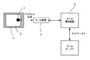
以下に、本発明に係る実施の形態について図面を参照しながら説明する。図1は、本発明の一実施の形態による製品保証管理システムの構成例を示す図である。図1に示すように、本実施の形態による製品保証管理システムは、梱包箱3により梱包されているタグ1及び製品2と、リード/ライト(R/W)装置4と、ネットワーク6を介してデータサーバ7と関連付けされるデータ管理装置5と、を含んでいる。上記製品保証管理システムにおいて、タグ1及び製品2を取り出すためには、梱包を解く必要がある。
【0022】
タグ1は、リード/ライト装置4との間で例えばワイヤレス(無線)でデータ(情報)の送受信を行うこと可能であり、梱包箱3の少なくとも一部は、電波を透過させる材質(例えば、発泡スチロールあるいはダンボール紙)により構成されている。リード/ライト装置4は、タグ1の情報を無線により読み取る機能と書き込む機能とを有し、さらに、データ管理装置5に接続され、タグ1内の情報の読み取り或いは書き込みに関連する情報の交換を行う機能も有している。要するに、外部と記憶部とのデータのやり取りを行うインターフェイス部を有している。
【0023】
データ管理装置5は、リード/ライト装置4とタグ1に関連した情報の交換を行う機能と、タグ1に関連する情報(例えば、製品コード情報や販売店コード情報など)を保持している。さらに、データ管理装置5は、ネットワーク6に接続されており、タグ1の管理に必要な情報を、随時、外部のデータサーバ7から取得し、タグ1の管理情報を外部のデータサーバ7に送信する機能を有する。
【0024】
図2は、本実施の形態によるタグの構成例を示す機能ブロック図であり、図3は、リード/ライト装置の構成例を示す機能ブロック図であり、図4は、本実施の形態によるデータ管理装置の機能ブロック図である。図1から図4までを参照して、本実施の形態による製品保証管理システムを構成する各装置の機能を詳細に説明する。
【0025】
図2で示すように、タグ1は、送受信用アンテナ(ループコイルアンテナ)11と、送受信部12と、変調部13と、制御部14と、記憶部15と、復調部16と、電源部17と、を有している。送受信用アンテナ11は、リード/ライト装置4から送信される電波を受信する。受信した電波に含まれるデータ信号は、RF(高周波回路)で構成された送受信部12により、ベースバンド信号あるいは中間周波数(IF)信号にダウンコンバートする等の処理が施された後に、受信信号の復調処理を行う復調部16で元の信号に復調される。
【0026】
復調された信号に関して、制御部14によりリード/ライト装置4からの指令や受信データの内容等が解析される。制御部14は、リード/ライト装置4からの指令に基づいて、記憶部15の記憶内容の書き換え或いは新しいデータの書き込み等を行う。さらに、受信時には、制御部14は、送受信部12及び復調部16に対して、受信のための制御を行う。
【0027】
さらに、制御部14は、リード/ライト装置4からの指令に基づいて、タグ1が記憶部15に保存しているデータを送信するための制御を変調部13或いは送受信部12に対して行い、記憶部15から必要なデータ信号を取り出し、変調部13にデータ信号を送る。データ信号は、変調部13において、無線伝送用のフォーマットに変換され、送受信部12において特定の無線周波数帯にアップコンバートされ、データ信号は、最終的に、送受信用アンテナ11からリード/ライト装置4に向けて送信される。
【0028】
尚、上述したようにリード/ライト装置4から送信される電波による通信に先立って、電波を送受信用アンテナ11で受信すると、電磁誘導現象により、この送受信用アンテナ11のコイルに電流が流れ発電される。電源部17は、この発電された電力VCを用いて、各部12から16までに対して電力を供給する。また、記憶部15内の記憶素子は、例えばEEPROM等の不揮発性素子により構成されており、記憶内容の保持に電力(電源)を必要としない。このため、タグ1は、電池等の内蔵バッテリーを必要としない。
【0029】
図3に示すように、リード/ライト装置4は、送受信用アンテナ(ループコイルアンテナ)41と、送受信部42と、変調部43と、制御部44と、記憶部45と、復調部46と、電源部47と、入力部48と、表示部49と、印字部50とを有している。
【0030】
送受信用アンテナ41は、タグ1から送信される電波を受信する。受信した電波に含まれるデータ信号は、RF(高周波回路)で構成された送受信部42により、ベースバンド信号あるいは中間周波数(IF)信号にダウンコンバートする等の処理が施された後に、受信信号の復調処理を行う復調部46で元の信号に復調される。復調された信号は、制御部44により受信データの内容等が解析され、必要に応じて、受信データが記憶部45に保存され、或いは、データ管理装置に送られる。
【0031】
また、制御部44は、受信時に、送受信部42及び復調部46に対して、各制御を行う。さらに、制御部44は、表示部49にデータの内容を表示させ、或いは、印字部(プリンタ)50にデータの内容を印字させるように指示する。また、制御部44は、タグ1に送信するデータをデータ管理装置5から取得し、或いは、記憶部45に保存しているデータを読み出して、変調部43に送る。その際に、制御部44は、データを送信するための制御を変調部43或いは送受信部42に対して行う。データ信号は、変調部43において無線伝送用のフォーマットに変換され、送受信部42において特定の無線周波数帯にアップコンバートされ、最終的に、データ信号は、送受信用アンテナ41からタグ1に向けて送信される。
【0032】
また、電源部47は、制御部44により制御され、各部に電力VDを供給する機能を有し、入力部48(例えば、押しボタンスイッチ)は、利用者からのリード/ライト装置4に対する操作を制御部44に伝達する機能を有している。また、表示部49(例えば、液晶ディスプレイ)は、データや操作内容を表示する機能を有し、印字部50は、データや保証内容を印字する機能を有している。
【0033】
図4はデータ管理装置5の構成例を示す機能ブロック図である。図4に示すように、データ管理装置5は、制御部54と、記憶部55と、電源部57と、入力部58と、表示部59と、入出力インターフェイス部60とを有している。データ管理装置5においては、リード/ライト装置4から送られたタグ1の情報(データ)は、入出力インターフェイス部60を経由して、制御部54に送られる。タグ1の情報は、制御部54の指令に基づいて記憶部55に格納され、また、必要に応じてインターネットやイントラネットを通じて、外部のサーバー等に送られる。制御部54は、タグ1の情報を表示部59に表示するための機能を有している。
【0034】
また、制御部54は、入出力インターフェイス部60を経由して外部のサーバーから取得したタグ情報又は記憶部55に保存してあるタグ情報を、入出力インターフェイス部60を経由してリード/ライト装置4に送信する。電源部57は、制御部54により制御され、各部に電力VEを供給する機能を有し、入力部58(例えば、キーボードやマウス)は、利用者からのデータ管理装置に対する操作を制御部54に伝達し、又は、タグ1に送信するデータを入力するための機能を有している。また、表示部59(例えば、モニタ)は、データや操作内容を表示する機能を有し、印字部50(図3)は、タグ情報等のデータを印字する機能を有している。
【0035】
図5は、本実施の形態によるタグの記憶レコードの構成例を示す図である。タグ1の記憶レコードは、タグID70と、製品コード71と、購入年月日コード72と、販売店コード73と、その他のオプション情報を記憶するn個のレコード74−1〜74−nと、を含んで構成されており、各々のレコードが例えば2進数のビット列を用いて記憶されている。
【0036】
タグID70は、そのタグ自体に固有のIDであり、個々のタグ1を識別するために使用され、タグ1の履歴の把握や、複数のアンテナを設置した場合における読み取り対応等に利用できる。例えば、複数のアンテナを設置して複数のタグの読み取りを同時に行うシステムでは、アンテナAから読み取ったタグ信号Aと、アンテナAとは別のアンテナBから読み取ったタグ信号Bが、同じタグのものかどうかを識別することが必要である。識別するためのIDがタグに付与されておらず、かつ読み取ったタグ信号Aとタグ信号Bとが異なるタグであった場合において、たまたまタグ信号Aの内容とタグ信号Bの内容が同じであると、タグの読み取り装置が“タグ信号Aとタグ信号Bは同一であるという”誤った判断をしてしまう可能性がある。
【0037】
タグIDの付与方法としては、別のタグのIDと重複しないように規格化されており、例として、64ビットの2進数で構成されている。製品コード71は、その製品に固有のIDであり、どの製品に付随しているタグであるかを識別するためのものである。購入年月日コード72は、顧客が製品を購入した年月日を記憶するためのものであり、販売店コード73は、顧客が購入した店舗名を識別するためのものである。オプションレコード74−1から74−nは、上記のレコード以外の付加的な情報を記憶するための領域であり、一般的な最低限の製品保証管理のみを対象とする場合には必ずしも用いる必要がない。
【0038】
ここで、タグID70と製品コード71とは1対1に対応しており、タグID70を製品コード71として用いることも可能であり、この場合は、製品コード71をタグID70の形式に沿って記載すれば良い。但し、製品コード71のコードのつけ方に製品製造者の都合などにより独自性を持たせたい場合には、タグID70と製品コード71とを別々に設けた方がナンバリングの自由度が増えるため都合が良い。
【0039】
図6は、本実施の形態による製品保証管理処理の流れを示すフローチャート図である。主に図6を参照し、適宜図1から図5までを参照しつつ、製品保証管理の方法について説明を行う。図6に示すように、まず、ステップS11において、製品名及び保証内容等を記憶させるために、製品2及びタグ1を梱包する前に、タグID70と製品コード71の書き込み処理を、リード/ライト装置4を用いて行う。ステップS12において、完成した製品2とタグ1とは、梱包箱3内に入れられ梱包される。ステップS13において、製品2は製造元から出荷され、物流過程を経て販売店の店頭に陳列される。ステップS14において、顧客が製品2を購入したか否かを判断する。顧客が製品2を購入したと判断された場合には、ステップS15に進む。
【0040】
ステップS15において、販売店の店員は、リード/ライト装置4を用いて、タグ1の情報を読み取り、データ管理装置5に送信する。データ管理装置5は、タグ1の書き込みに必要な情報(例えば、購入年月日コード72、販売店コード73など)をリード/ライト装置4に送信する。この時点で、購入年月日コード72のような製品の保証に関する情報の他に、例えば、タグ1のオプションレコード74−1から74−nに、例えば、製品の値段や購入者名等の有用な情報をリード/ライト装置4に送信し、製品管理を同時に行っても良い。
【0041】
ステップS16において、リード/ライト装置4は、タグ1に購入年月日コード72と販売店コード73との書き込みを行う。また、この際に、リード/ライト装置4は、製品の値段や購入者名等の情報をタグ1のオプションレコード74−1から74−nのいずれかに書き込んでも良い。また、この際に、リード/ライト装置4は、タグ1の情報の一部あるいは全部を印字部50により打ち出して、保証書として顧客に渡しても良い。
【0042】
ステップS17において、リード/ライト装置4は、タグ1に書き込んだデータの情報をデータ管理装置5に転送し、データ管理装置5は、タグ1に書き込んだ情報を保存し、或いは、タグ1の書き換え項目に相当する情報を書き換える。更に、データ管理装置5は、ネットワーク6等を通じて外部の管理サーバー7や製造者の商品管理サーバーに送信しても良い。以上のような方法により製品保証を行うことにより、製品の梱包を解くことなしに製品保証の管理を行うことが可能になる。
【0043】
図7は、本実施の形態による製品保証管理システムの具体的な構成例を示す図である。図8は、本実施の形態による製品保証管理方法の具体的な事例を示したデータフロー図であり、図7のシステムによる製品保証管理システムにおける一部の処理の流れを示すフローチャート図である。図7と図8とを主に参照して、以下に、本実施の形態による製品保証管理システムの具体的な事例について説明する。本実施の形態において、タグ1は、図5に示した記憶レコードの構成を有しており、製品が製造工場で生産されてから顧客が販売店で購入するまでの処理方法は、図6を参照して説明した方法と同様である。
【0044】
その後に、顧客が販売店で製品を購入した後にサポートの必要性が発生し、サポートセンターでサポートを受けた場合の製品保証管理の方法について、図8に基づいて説明を行う。なお、図7に示すタグ81−1,81−2,81−3は同一のタグであるが、タグの記憶レコードの内容が異なっている。タグ81−1は、タグID70と製品コード71とに対して情報が書き込まれているが、その他の記憶レコードに対しては情報が書き込まれていない。タグ81−2は、購入年月日コード72と販売店コード73に対して新たに追加で情報が書き込まれている。タグ81−3は、オプション“1”74−1に対して、修理履歴の情報が新たに追加で書き込まれている。
【0045】
製品を製造する製造工場80において、リード/ライト装置82によりタグ81−1に書きこまれたタグID70と製品ID71とは、データ管理装置83に転送されて蓄積され、タグ情報を統合的に管理している製品管理サーバー110に送られる。製品管理サーバー110の構成は、図4に示すデータ管理装置の構成とほぼ同様であるが、図4に示す制御部54に加えて、データ管理装置から送信されるタグの情報を一元的に管理し各データ管理装置に必要な情報を発信する機能が追加されている。製品を販売する販売店90において顧客が製品を購入した時に、リード/ライト装置92は、タグ81−2の記憶内容(タグID70、製品ID71)を読み取り、データ管理装置93に転送する。
【0046】
リード/ライト装置92は、データ管理装置93からタグ81−2に付随する情報(価格情報等のオプション)を取得し、購入年月日コード72、販売店コード73とともにタグ81−2に書き込み、タグ81−2に書きこんだ情報を、データ管理装置93に転送するとともに、さらに製品管理サーバー110にも転送する。
【0047】
次いで、顧客が製品を購入した後に、サポートセンター100において修理或いはサポート(ソフトウエアのバージョンアップ等)が必要ななった場合について説明する。その後のプロセスの具体例については、図8の流れ図を中心に説明する。ステップS21において、リード/ライト装置102は、タグ81−3に記憶されているタグID70、製品コード71、購入年月日72等の記憶レコードの一部或いは全てを読み込み、データ管理装置103に対してタグ81−3の記憶内容を転送する。
【0048】
データ管理装置103は、製品管理サーバー110に対してタグ81−3に記憶されている情報を送付する。ステップS22において、製品管理サーバー110は、送られたタグ81−3の情報に基づいて、その製品が保証期間内か否かを判断する。但し、製品が保証期間内か否かを判断するのは、必ずしも製品管理サーバーでなくても良く、データ管理装置103が、予め判断に必要な製品毎の保証期間、保証内容等を蓄えておくことにより、データ管理装置103に判断させることも可能である。
【0049】
製品が保証期間内であり、かつ、保証が有効な内容であると判断された場合には、ステップS23に進み、無償修理や無償サポートが行われる。製品が保証期間外であるか、若しくは、保証内容に合致していないと判断された場合には、ステップS24に進み、有償修理或いは有償サポートを行う。ステップS25において、リ−ド/ライト装置102は、タグ81−3のオプションレコードのいずれかに修理履歴あるいはサポート履歴等の情報の書き込みを行う。
【0050】
ステップS26において、リ−ド/ライト装置102は、データ管理装置103或いは製品管理サーバー110にタグ81−3に書き込んだ内容を転送して保存する。以上のように、最終的にタグ81に書き込まれていた情報は、製品管理サーバー110内に保存/蓄積されるので、何らかの理由でタグ81を紛失したとしても製品保証情報が失われることがない。さらに、製品管理サーバー110が製品とタグとに関する情報を集中的に管理することにより、タグ81に関して記憶された情報を照合すれば、後にタグが不正に書き換えられたとしてもそれを見抜くことができ、従って、不正なタグの書き換えを防止することも可能である。
【0051】
例えば、タグID70或いは製品コード71は、製品工場の出荷時に一度書き込めば、タグ81を再利用しない限りは書き換えの必要がないため、タグ81には1回だけしか情報を書き込むことができないようにするのが好ましい。また、購入年月日コード72或いは販売店コードは、再販売を行わない限り製品の購入時に1回だけタグ81に情報を書き込めれば良いため、購入年月日の改竄等により不正な保証を受けることを防ぐためにも、1回だけタグに情報を書き込むことができるようにするのが望ましい。また、修理やサポート内容に対しても、不正に書き換えができないように、オプションレコードに追加する形で書き込まれるように構成するのが好ましい。
【0052】
さらに、リード/ライト装置82、92、102の属性(工場内に設置されているものか、或いは、販売店に設置されているものかなど)に基づいて、タグ81に書き込み或いは書き換えが可能な記憶レコードを限定することにより、セキュリティを強化することができる。
【0053】
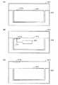
図9(A)から図9(C)までを参照して、タグの配置に関する種々の態様について説明する。図9(A)は、インターフェイス部に関する第1の取り付け形態例を示す図である。図9(A)に示すように、梱包箱201内に商品の収容部を形成する梱包材205が配置され、この商品収容部内に商品203が収容されている。商品203の表面にはタグ210aが貼り付けられている。
【0054】
図9(B)は、タグに関する第2の取り付け形態例を示す図である。図9(B)に示すように、梱包箱201内に商品、例えば電子機器を収容する電子機器収容部を形成する梱包材205が配置され、電子機器収容部内に電子機器(商品)203が収容されている。電子機器203にタグ210bが内蔵されている。この場合に、例えば、電子機器203内の制御部207とタグ210bとの間が有線によるデータ通信可能な状態になっていても良い。
【0055】
図9(C)は、タグに関する第3の取り付け形態例を示す図である。図9(C)に示すように、梱包箱201内に商品を形成する梱包材205が配置され、商品収容部内に商品203が収容されている。タグ210cは梱包箱201の内面(又は外面でも良い)に貼付されている。上記いずれかの形態により、タグと商品とが関連付けされることになる。
【0056】
本実施の形態によるタグを用いると、販売店において保証内容が記載あるいは記憶された証明物を梱包箱あるいはビニルの封筒等の保護材より一旦取り出して、購入店舗及び購入年月日を証明物に記入あるいは記憶させ、再び証明物を梱包箱あるいはビニルの封筒等の保護材に入れる作業をすることなしに、購入店舗及び購入年月日を認識させることが可能である。従って、工場で製品を梱包した後は、消費者が製品を使用する時点まで、証明物は、特に梱包箱から取り出す必要はなくなるので、販売時のコストを低減できるという利点がある。さらに、製品を工場出荷時から消費者の製品購入後のサポート時まで、製品管理サーバーにより一元的に管理することにより、製品の流通状況或いはサポート状態の把握が容易になるという利点がある。
【0057】
以上、本実施の形態に沿って説明したが、本発明はこれらの例に限定されるものではなく、例えば以下に示すような種々の変形が可能であるのは言うまでもない。
【0058】
例えば、上記の実施例においては、製品(商品)の保証期間に関する管理を行う場合を例にして説明したが、商品管理システムとしてPOSシステムに応用することも可能である。例えば、図7に示す販売店においてリード/ライト装置92を用いて、販売状況に関するデータ管理を行うこともできる。この際、例えば、図5に示すオプション(1)74−1〜オプション(n)74−nのいずれかに、現在の販売価格に関連する情報を記憶させておいても良い。商品の販売価格は、販売時期や他店との関係などにより変動する可能性があるので、例えば、初期設定価格をオプション(1)74−1に、次に設定した価格をオプション(2)74−2にというように、随時価格変動に伴って記憶させておけば、現在の価格をいつでもリード/ライト装置92を用いて知ることが出来るとともに、価格の推移を知ることも出来る。この場合には、価格の変更日時に関連する情報も価格情報と対応付けて記憶させることができる。上記タグを用いると、データ表示部を有するリード/ライト装置92を所持した販売員は、現在の価格を随時知ることができるとともに、販売価格の推移に関しても手元で知ることができる。尚、リード/ライト装置92をPOSシステム内に組み込むことも可能である。一般的なレジスターの代わりにリード/ライト装置92を用いることも可能である。
【0059】
また、例えば、タグにより管理されている対象として商品を例にして説明したが、サービスを受ける権利を証明するカード又は券などを対象としても良い。この場合には、サービスを受ける権利を有する期間が、商品の保証期間に対応することになる。
【0060】
リード/ライト装置92とタグ81との間は、1対1のデータのやり取りでも良いし、同報により一括してある対象商品群に対して情報を書き込んだり、更新したりすることも可能である。
【0061】
【発明の効果】
本発明によるタグを用いると、販売店において、保証内容が記載あるいは記憶された証明物を梱包箱あるいはビニルの封筒等の保護材より一旦取り出して、購入店舗及び購入年月日を証明物に記入あるいは記憶させ、再び証明物を梱包箱あるいはビニルの封筒等の保護材に入れる作業を省略できるため、工場で製品を梱包した後は、消費者が製品を使用する時点まで、証明物は、特に梱包箱から取り出す必要はなくなるので、販売時のコスト低減に効果がある。
【0062】
さらに、製品を工場出荷時から消費者の製品購入後のサポート時まで、製品管理サーバーにより一元的に管理することにより、製品の流通状況あるいはサポート状態の把握が容易になる効果がある。
【図面の簡単な説明】
【図1】本発明の一実施の形態による製品保証管理システムの構成例を示すブロック図である。
【図2】本発明の一実施の形態によるタグの構成例を示す機能ブロックである。
【図3】本発明の一実施の形態によるリード/ライト装置の構成例を示す機能ブロック図である。
【図4】本発明の一実施の形態によるデータ管理装置の構成例を示す機能ブロック図である。
【図5】本発明の一実施の形態によるタグの記憶レコードのデータ構成例を示す図である。
【図6】本発明の一実施の形態による製品保証管理処理の流れを示すフローチャート図である。
【図7】本発明の一実施の形態による製品保証管理システムの構成例を具体的に示した図である。
【図8】本発明の一実施の形態による製品保証管理処理の一部の流れを示すフローチャート図である。
【図9】図9(A)から(C)までは、本発明の一実施の形態によるタグの取り付け形態の例を示す図である。
【図10】一般的なRFIDタグの構成例を示すブロック図である。
【符号の説明】
1 タグ
2 製品
3 梱包箱
4 リード/ライト装置
5 データ管理装置
11、41 送受信用アンテナ
12、42 送受信部
13、43 変調部
14、44、54 制御部
15、45、55 記憶部
16、46 復調部
17、47、57 タグの電源部
48、58 入力部
49、59 表示部
50 印字部
60 入出力インターフェイス部
70 タグID記憶レコード
71 製品コード記憶レコード
72 購入年月日コード記憶レコード
73 販売店コード記憶レコード
74−1〜74−n オプション記憶レコード
80 製造工場内の製品保証システム
81−1、81−2、81−3 タグ(同じものであるが、記憶内容が異なる)
82、92、102 リード/ライト装置
83、93、103 データ管理装置
90 販売店内の製品保証システム
100 サポートセンター内の製品保証システム
110 製品管理サーバー[0001]
TECHNICAL FIELD OF THE INVENTION
The present invention relates to a tag and a product warranty management system using the tag, and more particularly to a tag related to a wireless data transmission technique.
[0002]
[Prior art]
In recent years, with the development of wireless communication technology, tags capable of reading / writing data by wireless communication have been developed. FIG. 10 is a diagram illustrating a configuration example of a tag using RFID (Radio Frequency Identification). As shown in FIG. 10, the RFID (wireless)
[0003]
The RFID (wireless)
[0004]
As an application example of such an
[0005]
[Patent Document 1]
JP-A-11-144012
[0006]
[Problems to be solved by the invention]
On the other hand, in a normal distribution process, a product manufactured by a manufacturer is sold to a customer by a retailer (seller) via a wholesaler or the like. At that time, the quality of many TVs, refrigerators and other durable consumer goods is guaranteed by manufacturers or dealers through free repairs for a certain period of time from the time of product purchase. These products are accompanied by a warranty card, and when the product is purchased, the warranty and the date of purchase are indicated on the warranty card to prove that the product was sold properly and determine the warranty period at the same time. You. When a customer purchases a product at a store, the date and time of purchase of the product and the store must be written or stamped on the warranty.
[0007]
However, in many cases, the warranty card is contained in a packing box, or is put in a vinyl envelope and affixed to the outside of the packing box. In such a case, it is necessary to temporarily take out the warranty from the packing box or vinyl envelope at the store, write or stamp the store and date of purchase on the warranty, and put the warranty back into the packing box or vinyl envelope. is there. Such a work action causes an increase in time cost or human cost.
[0008]
In addition, there is a problem that the store does not enter the name of the store or the date of purchase on the warranty card, because the entry is troublesome, or the contents of the warranty card are written on paper. There is also a problem that it is easily falsified intentionally.
SUMMARY OF THE INVENTION An object of the present invention is to provide a tag and a product assurance management system using the tag, in which the contents of the guarantee can be written while the product is packed.
[0009]
[Means for Solving the Problems]
According to one aspect of the present invention, a tag associated with a product, a product code storage area for storing a product code for identifying the product, and a purchase date for identifying a purchase date and time of the product A storage unit having a purchase date code storage area for storing a day code, a store code storage area for storing a store code for identifying the store where the product was purchased, There is provided a tag including an interface unit for exchanging data, and a control unit for controlling operations of the interface unit and the storage unit and a data transfer process between the two. The interface unit preferably has a communication unit including a wireless antenna, a transmission / reception unit, a modulation unit, and a demodulation unit. According to this configuration, it is possible to exchange information wirelessly with the outside. In addition, it is preferable that the control unit starts the control operation with electric power supplied wirelessly when the interface unit receives data transmitted wirelessly from the outside. This eliminates the need for preparing a separate power supply for the operation of the tag.
[0010]
It is preferable that the storage unit further has a tag ID storage area for storing a unique tag ID for identifying the own tag from other tags. Further, it is preferable that the control unit is configured to operate only when data transmitted by designating the tag ID from outside is received. In this way, it is possible to prevent a malfunction at the time of reading / writing from / to the tag.
[0011]
Preferably, the product code storage area is a storage area in which writing is permitted only once before or at the time of product shipment, and only reading is permitted and writing is prohibited after product shipment. After the product is shipped, only the genuine product can be managed by preventing the product code from being rewritten.
[0012]
It is preferable that the purchase date code is a storage area in which writing to the product code storage area is confirmed, and in which writing is permitted only once at the time of product purchase or after purchase. If the product code is not stored, it is not a product that has been officially shipped, and the purchase date code is not assigned. Once the purchase date code is given, it becomes a reference time (at the start of the period) such as a warranty period. Therefore, data rewriting is prohibited so that it cannot be changed.
[0013]
It is preferable that the store code is a storage region in which writing to the product code storage region is confirmed, and which is permitted to be written only once when the product is purchased or after the purchase. If the product code is not stored, the product is not a product that has been officially shipped, and the store code is not assigned. Once the store code is assigned, the store code that specifies the store that will bring the product in when assurance is provided is prohibited, so that rewriting of data is prohibited so that the store code cannot be changed.
[0014]
According to another aspect of the present invention, the tag, a read / write device capable of reading or writing the code wirelessly, and transmitting data for writing to the tag to the read / write device, or There is provided a product management system comprising: a data management device that receives data read from the tag from the read / write device, saves data stored in the tag, and manages products.
According to the above-described product management system, data can be centrally managed based on the tag assigned to each product, thereby simplifying product management.
[0015]
It is preferable that the storage unit further includes a warranty period information code storage area for storing warranty period information regarding a product warranty period. Based on the warranty period and the date and time of product sale, it is possible to accurately determine whether or not the product is within the warranty period.
[0016]
Further, it is a product management server that centrally manages product information, and can receive information read from the tag or information written in the tag at any time via the data management device. With this configuration, the storage information is updated and the latest information currently stored in the tag is retained, and information management on the product can be performed quickly and accurately.
[0017]
In other words, at the stage before packing the product, the product code for identifying the product can be described on the tag, but the purchase date code for identifying the date and time when the product was purchased, and the sales date when the product was sold Since the store code for identifying the store cannot be described, it is not possible to write information on all guarantee contents in the tag before packing.
[0018]
Therefore, when the purchaser purchases the product, the purchase date code and the store code are wirelessly written from the outside to the tag, so that all information on the warranty content can be stored without the need to unpack the tag. It becomes possible to fill in.
[0019]
Further, at the time of purchase of the product, the store reads the information of the tag attached to the product, and stores the content written in the tag in a data management device that manages the information of the tag, so that the information of the barcode can be separately stored. The product management can be easily performed without having to read and manage the product.
[0020]
BEST MODE FOR CARRYING OUT THE INVENTION
In the present specification, a product or a commodity is defined as a broad concept including an object to be traded or an intangible service, in addition to a product or a commodity in a general sense.
In addition, the interface unit includes a wireless communication unit when data is exchanged between the outside and the storage unit by wireless communication, for example.
[0021]
Hereinafter, embodiments according to the present invention will be described with reference to the drawings. FIG. 1 is a diagram illustrating a configuration example of a product warranty management system according to an embodiment of the present invention. As shown in FIG. 1, the product warranty management system according to the present embodiment includes a
[0022]
The
[0023]
The data management device 5 has a function of exchanging information related to the
[0024]
FIG. 2 is a functional block diagram illustrating a configuration example of a tag according to the present embodiment, FIG. 3 is a functional block diagram illustrating a configuration example of a read / write device, and FIG. 4 is a data block diagram according to the present embodiment. It is a functional block diagram of a management device. With reference to FIG. 1 to FIG. 4, the function of each device constituting the product warranty management system according to the present embodiment will be described in detail.
[0025]
As shown in FIG. 2, the
[0026]
With respect to the demodulated signal, the
[0027]
Further, the
[0028]
As described above, when a radio wave is received by the transmission /
[0029]
As shown in FIG. 3, the read / write device 4 includes a transmission / reception antenna (loop coil antenna) 41, a transmission /
[0030]
The transmitting / receiving
[0031]
Further, the
[0032]
The
[0033]
FIG. 4 is a functional block diagram illustrating a configuration example of the data management device 5. As shown in FIG. 4, the data management device 5 includes a
[0034]
Further, the
[0035]
FIG. 5 is a diagram showing a configuration example of a tag storage record according to the present embodiment. The storage records of the
[0036]
The
[0037]
The tag ID assignment method is standardized so as not to overlap with the ID of another tag, and for example, is constituted by a 64-bit binary number. The
[0038]
Here, the
[0039]
FIG. 6 is a flowchart illustrating the flow of the product warranty management process according to the present embodiment. The method of product warranty management will be described mainly with reference to FIG. 6 and appropriately referring to FIG. 1 to FIG. As shown in FIG. 6, first, in step S11, in order to store the product name and the warranty details, before packing the
[0040]
In step S <b> 15, the sales clerk uses the read / write device 4 to read the information of the
[0041]
In step S16, the read / write device 4 writes the
[0042]
In step S17, the read / write device 4 transfers the information of the data written in the
[0043]
FIG. 7 is a diagram illustrating a specific configuration example of the product warranty management system according to the present embodiment. FIG. 8 is a data flow diagram showing a specific example of the product warranty management method according to the present embodiment, and is a flowchart showing a part of the flow of processing in the product warranty management system by the system of FIG. With reference mainly to FIGS. 7 and 8, a specific example of the product warranty management system according to the present embodiment will be described below. In the present embodiment, the
[0044]
Then, a method of managing product warranty in the case where support is required after a customer purchases a product at a store and the support center receives the support will be described with reference to FIG. Although the tags 81-1, 81-2, 81-3 shown in FIG. 7 are the same tag, the contents of the tag storage records are different. In the tag 81-1, information is written in the
[0045]
In the
[0046]
The read /
[0047]
Next, a case where repair or support (upgrading software, etc.) is required at the
[0048]
The
[0049]
If it is determined that the product is within the warranty period and the warranty is valid, the process proceeds to step S23, where free repair and free support are performed. If it is determined that the product is out of the warranty period or does not match the warranty content, the process proceeds to step S24 to perform paid repair or paid support. In step S25, the read /
[0050]
In step S26, the read /
[0051]
For example, if the
[0052]
Further, it is possible to write or rewrite the tag 81 based on the attributes of the read /
[0053]
With reference to FIGS. 9A to 9C, various modes regarding the arrangement of tags will be described. FIG. 9A is a diagram illustrating a first mounting example of the interface section. As shown in FIG. 9A, a packing
[0054]
FIG. 9B is a diagram illustrating a second example of a mounting mode for the tag. As shown in FIG. 9B, a packing
[0055]
FIG. 9C is a diagram showing a third example of a mounting mode for the tag. As shown in FIG. 9C, a packing
[0056]
When the tag according to the present embodiment is used, the proof that the warranty content is described or stored in the store is once removed from the protective material such as a packing box or a vinyl envelope, and the purchase store and the date of purchase are used as the proof. It is possible to make it possible to recognize the store and the date of purchase without having to fill in or memorize it and work again to put the certificate in a protective material such as a packing box or a vinyl envelope. Therefore, after the product is packed in the factory, the certificate does not need to be taken out of the packing box until the consumer uses the product, so that there is an advantage that the cost at the time of sale can be reduced. Furthermore, there is an advantage that the product distribution server or the support status can be easily grasped by integrally managing the product from the factory shipment to the support after the consumer purchases the product by the product management server.
[0057]
Although the present embodiment has been described above, the present invention is not limited to these examples, and it goes without saying that various modifications as described below are possible.
[0058]
For example, in the above-described embodiment, the case of managing the warranty period of a product (article) has been described as an example, but the present invention can be applied to a POS system as an article management system. For example, data management relating to the sales situation can be performed using the read /
[0059]
Further, for example, although the description has been given by taking a product as an example of a target managed by a tag, a card or a ticket proving the right to receive a service may be a target. In this case, the period during which the user has the right to receive the service corresponds to the warranty period of the product.
[0060]
One-to-one exchange of data may be performed between the read /
[0061]
【The invention's effect】
When the tag according to the present invention is used, at the store, the proof that the warranty is described or stored is once removed from the protective material such as a packing box or a vinyl envelope, and the purchase store and the date of purchase are written on the proof. Alternatively, it is possible to omit the work of memorizing and putting the proof in a protective material such as a packing box or a vinyl envelope again, so after packing the product at the factory, the proof is in particular until the consumer uses the product. Since it is not necessary to take out from the packing box, it is effective in reducing costs at the time of sale.
[0062]
In addition, since the products are centrally managed by the product management server from the time of shipment from the factory to the time of support after the consumer purchases the products, there is an effect that the distribution status of the products or the support status can be easily grasped.
[Brief description of the drawings]
FIG. 1 is a block diagram illustrating a configuration example of a product warranty management system according to an embodiment of the present invention.
FIG. 2 is a functional block diagram illustrating a configuration example of a tag according to an embodiment of the present invention.
FIG. 3 is a functional block diagram illustrating a configuration example of a read / write device according to an embodiment of the present invention.
FIG. 4 is a functional block diagram illustrating a configuration example of a data management device according to an embodiment of the present invention.
FIG. 5 is a diagram showing a data configuration example of a tag storage record according to an embodiment of the present invention.
FIG. 6 is a flowchart illustrating a flow of a product warranty management process according to the embodiment of the present invention.
FIG. 7 is a diagram specifically showing a configuration example of a product warranty management system according to an embodiment of the present invention.
FIG. 8 is a flowchart showing a partial flow of a product warranty management process according to an embodiment of the present invention.
FIGS. 9A to 9C are diagrams illustrating examples of a tag attachment mode according to an embodiment of the present invention.
FIG. 10 is a block diagram illustrating a configuration example of a general RFID tag.
[Explanation of symbols]
1 tag
2 Products
3 packing box
4 Read / write device
5 Data management device
11, 41 Transmission / reception antenna
12, 42 transceiver
13, 43 modulator
14, 44, 54 control unit
15, 45, 55 storage unit
16, 46 demodulation unit
17, 47, 57 Tag power supply
48, 58 input unit
49, 59 display
50 Printing section
60 Input / output interface
70 Tag ID storage record
71 Product code storage record
72 Purchase date code storage record
73 Store code storage record
74-1 to 74-n option storage record
80 Product assurance system in manufacturing plant
81-1, 81-2, 81-3 tags (same but with different storage contents)
82, 92, 102 read / write device
83, 93, 103 Data management device
90 Product assurance system in the store
100 Product Warranty System in Support Center
110 Product Management Server
Claims (13)
Translated fromJapanese前記製品を識別するための製品コードを記憶する製品コード記憶領域と、前記製品の購入日時を識別するための購入年月日コードを記憶する購入年月日コード記憶領域と、前記製品を購入した販売店を識別するための販売店コードを記憶する販売店コード記憶領域と、を有する記憶部と、
外部との情報のやり取りを行うインターフェイス部と、
該インターフェイス部と前記記憶部との間のデータ転送処理を制御する制御部と
を備えたタグ。A tag associated with the product,
A product code storage area for storing a product code for identifying the product, a purchase date code storage area for storing a purchase date code for identifying the date and time of purchase of the product, and A storage unit having a store code storage area for storing a store code for identifying the store,
An interface for exchanging information with the outside;
A tag comprising: a control unit that controls a data transfer process between the interface unit and the storage unit.
請求項1に記載のコードをワイヤレスで読み取り又は書き込みが可能なリード/ライト装置と、
前記タグに書き込むためのデータを前記リード/ライト装置に送信し、又は、前記タグから読み込まれたデータを前記リード/ライト装置から受信し、前記タグに記憶されているデータを保存し製品に関する管理を行うデータ管理装置と
を有する製品管理システム。A tag according to any one of claims 1 to 9,
A read / write device capable of reading or writing the code according to claim 1 wirelessly,
Data for writing to the tag is transmitted to the read / write device, or data read from the tag is received from the read / write device, and the data stored in the tag is stored to manage products. Product management system having a data management device for performing
請求項10に記載の製品管理システム。The product management system according to claim 10, wherein the storage unit further includes a warranty period information code storage area for storing warranty period information regarding a product warranty period.
Priority Applications (1)
| Application Number | Priority Date | Filing Date | Title |
|---|---|---|---|
| JP2003058434AJP2004272344A (en) | 2003-03-05 | 2003-03-05 | Tags and product warranty management system using tags |
Applications Claiming Priority (1)
| Application Number | Priority Date | Filing Date | Title |
|---|---|---|---|
| JP2003058434AJP2004272344A (en) | 2003-03-05 | 2003-03-05 | Tags and product warranty management system using tags |
Publications (1)
| Publication Number | Publication Date |
|---|---|
| JP2004272344Atrue JP2004272344A (en) | 2004-09-30 |
Family
ID=33121546
Family Applications (1)
| Application Number | Title | Priority Date | Filing Date |
|---|---|---|---|
| JP2003058434APendingJP2004272344A (en) | 2003-03-05 | 2003-03-05 | Tags and product warranty management system using tags |
Country Status (1)
| Country | Link |
|---|---|
| JP (1) | JP2004272344A (en) |
Cited By (4)
| Publication number | Priority date | Publication date | Assignee | Title |
|---|---|---|---|---|
| GB2419716A (en)* | 2004-10-29 | 2006-05-03 | Hewlett Packard Development Co | Storage of purchase-related information |
| JP2007026844A (en)* | 2005-07-15 | 2007-02-01 | Matsushita Electric Ind Co Ltd | battery |
| US7703687B2 (en) | 2004-10-22 | 2010-04-27 | Kabushiki Kaisha Sato | Label |
| US9286613B2 (en) | 2004-10-29 | 2016-03-15 | Hewlett-Packard Development Company, L.P. | Ordering of goods or services using memory for storing digital content |
- 2003
- 2003-03-05JPJP2003058434Apatent/JP2004272344A/enactivePending
Cited By (6)
| Publication number | Priority date | Publication date | Assignee | Title |
|---|---|---|---|---|
| US7703687B2 (en) | 2004-10-22 | 2010-04-27 | Kabushiki Kaisha Sato | Label |
| GB2419716A (en)* | 2004-10-29 | 2006-05-03 | Hewlett Packard Development Co | Storage of purchase-related information |
| GB2419716B (en)* | 2004-10-29 | 2010-12-08 | Hewlett Packard Development Co | Storage of purchase-related information |
| US8463663B2 (en) | 2004-10-29 | 2013-06-11 | Hewlett-Packard Development Company, L.P. | Storage of purchase-related information |
| US9286613B2 (en) | 2004-10-29 | 2016-03-15 | Hewlett-Packard Development Company, L.P. | Ordering of goods or services using memory for storing digital content |
| JP2007026844A (en)* | 2005-07-15 | 2007-02-01 | Matsushita Electric Ind Co Ltd | battery |
Similar Documents
| Publication | Publication Date | Title |
|---|---|---|
| JP7507216B2 (en) | Smart Product Label Platform | |
| CA2443535C (en) | Lost and found system and method with optional product warranty registration | |
| US7196627B2 (en) | Control of packaged modules | |
| US20150032569A1 (en) | Service access using identifiers | |
| JP2010146555A (en) | Communication system and device configuration method | |
| TW200300891A (en) | Distribution management method and system | |
| JP2008197768A (en) | Non-contact memory built-in device and its sales management system | |
| IL175708A (en) | Merchandise management system, control program and information storage medium | |
| US20120044060A1 (en) | Electronic Device And Data Management System | |
| US20080046114A1 (en) | System, packaging, and method for distributing products | |
| JP2002236891A (en) | Radio tag with data display function | |
| JP2001331069A (en) | Image forming apparatus management method | |
| JP2004272344A (en) | Tags and product warranty management system using tags | |
| JP2012042995A (en) | Electronic device and information management system | |
| JP4503342B2 (en) | Goods management system | |
| JP2008234537A (en) | Forged merchandise detecting system and forged merchandise detecting method | |
| JPH1166435A (en) | Cash register | |
| KR20180102714A (en) | System and method for integrated managing of products history based on genuine certification information | |
| JP2007156774A (en) | Network system | |
| US20160078422A1 (en) | System and method for enhancing rfid tagged products in packages with multiple products | |
| FI123468B (en) | Checkout terminal system comprising an RFID reader and a transmitter | |
| JP6893810B2 (en) | Wireless tag readers and programs | |
| JP4521969B2 (en) | Product sales confirmation method and price tag | |
| JP4548164B2 (en) | Distribution management system | |
| JP3665118B2 (en) | Product management method and apparatus |
Legal Events
| Date | Code | Title | Description |
|---|---|---|---|
| A621 | Written request for application examination | Free format text:JAPANESE INTERMEDIATE CODE: A621 Effective date:20050810 | |
| A977 | Report on retrieval | Free format text:JAPANESE INTERMEDIATE CODE: A971007 Effective date:20070531 | |
| A131 | Notification of reasons for refusal | Free format text:JAPANESE INTERMEDIATE CODE: A131 Effective date:20070612 | |
| A521 | Request for written amendment filed | Free format text:JAPANESE INTERMEDIATE CODE: A523 Effective date:20070813 | |
| A02 | Decision of refusal | Free format text:JAPANESE INTERMEDIATE CODE: A02 Effective date:20080205 |