JP2004268730A - Attitude control method for unmanned helicopter - Google Patents
Attitude control method for unmanned helicopterDownload PDFInfo
- Publication number
- JP2004268730A JP2004268730AJP2003062329AJP2003062329AJP2004268730AJP 2004268730 AJP2004268730 AJP 2004268730AJP 2003062329 AJP2003062329 AJP 2003062329AJP 2003062329 AJP2003062329 AJP 2003062329AJP 2004268730 AJP2004268730 AJP 2004268730A
- Authority
- JP
- Japan
- Prior art keywords
- attitude
- pass filter
- output
- data
- control method
- Prior art date
- Legal status (The legal status is an assumption and is not a legal conclusion. Google has not performed a legal analysis and makes no representation as to the accuracy of the status listed.)
- Pending
Links
- 238000000034methodMethods0.000titleclaimsabstractdescription21
- 230000001133accelerationEffects0.000claimsabstractdescription46
- 238000010586diagramMethods0.000abstractdescription9
- 238000006243chemical reactionMethods0.000description3
- 230000007935neutral effectEffects0.000description3
- 230000005484gravityEffects0.000description2
- 230000005856abnormalityEffects0.000description1
- 238000001514detection methodMethods0.000description1
- 230000000694effectsEffects0.000description1
Images


Landscapes
- Control Of Position, Course, Altitude, Or Attitude Of Moving Bodies (AREA)
Abstract
Translated fromJapaneseDescription
Translated fromJapanese【0001】
【発明の属する技術分野】
本発明は、ジャイロセンサを用いた無人ヘリコプタの姿勢制御方法に関する。
【0002】
【従来の技術】
加速度センサを用いた飛行体の姿勢制御装置が特許文献1に記載されている。この姿勢制御装置は、目標姿勢角(Θx,Θy)を加速度センサの値(αx,αy)を用いて、
【0003】
Θx=αy/g,Θy=−αx/g (gは重力加速度)
として姿勢角を目標姿勢角に一致させるように制御する。これにより、テールロータの影響や風の外乱の影響を打ち消すことを可能としたものである。これは、機体の前後左右方向の方位を機体軸に固定した地球座標系の加速度が0になるからである。
【0004】
しかしながら、上記特許文献1の姿勢制御装置では、機体の速度が減速しにくくなり、操縦しにくいという問題点がある。すなわち、機体の前後左右方向の速度が0付近の場合は加速度を0にすると止まりやすくなる。しかし、一旦速度が発生した場合には、加速度を0にするように制御すると、速度が減速しにくくなり、停止できないまま飛行し機体が不安定になるおそれがある。
【0005】
【特許文献1】
特許第3189027号公報
【0006】
【発明が解決しようとする課題】
本発明は上記従来技術を考慮したものであって、飛行状態にかかわらずペイロードや風の外乱により姿勢角が変化しても安定して姿勢を制御可能な無人ヘリコプタの姿勢制御方法の提供を目的とする。
【0007】
【課題を解決するための手段】
前記目的を達成するため、本発明では、ジャイロセンサから出力される加速度データ及び姿勢データを用いた無人ヘリコプタの姿勢制御方法であって、前記加速度データを座標変換して地球座標系の慣性加速度データとし、この慣性加速度データをローパスフィルタに入力し、前記姿勢データをハイパスフィルタに入力し、前記ローパスフィルタの出力及び前記ハイパスフィルタの出力をミキシングしてハイブリッド姿勢角を作成し、このハイブリッド姿勢角に基づいて機体の姿勢制御を行うことを特徴とする無人ヘリコプタの姿勢制御方法を提供する。
【0008】
この構成によれば、慣性加速度データ(ローパスフィルタと通した低周波数成分)と姿勢データ(ハイパスフィルタを通した高周波数成分)とを組合わせたハイブリッド姿勢角に基づいて姿勢制御を行うため、機体の姿勢にかかわらずハイブリッド姿勢角の0点が常に姿勢角中立位置である制御原点(以下原点姿勢角という)となり、ホバリングの制御がしやすくなる。すなわち、ホバリングを行うことができる原点姿勢角は、ペイロード(メインロータによる積載負荷)や風向きによって異なってくる。例えば、ペイロードが大きくなるとメインロータの必要推力が増えるため、テールロータの推力も増える。これにより、これを打ち消すような向きにメインロータを傾ける必要があり、これにより原点姿勢角が傾く。同様に風の外乱がある場合には、これを打ち消すように原点姿勢角が逆方向に傾く。
【0009】
しかし、ハイブリッド姿勢角によれば、どのような飛行状態であっても、0点位置が姿勢角の中立位置となるため、ホバリングの制御を非常に簡単に行うことができる。
【0010】
好ましい構成例では、飛行状態に応じてローパスフィルタの出力とハイパスフィルタの出力の割合を変えることを特徴としている。
【0011】
この構成によれば、ローパスフィルタを通した加速度データとハイパスフィルタを通した姿勢データとの出力の割合を飛行状態に応じて変えるため、原点姿勢角が急激に変化する状況では加速度データの割合を多くしたハイブリッド姿勢角に基づいて制御し、通常の飛行状態では加速度データの割合を減らして制御することにより、加速度制御による減速のしにくさを伴うことなく、あらゆる飛行状態で安定して機体の姿勢を制御することができる。
【0012】
好ましい構成例では、前記飛行状態として離着陸状態及び方位変更状態を判別することを特徴としている。
【0013】
この構成によれば、機体の原点姿勢角が大きく変化する離着陸状態及び方位変更状態では、ハイブリッド姿勢角を加速度データ側に移動させて急激な原点姿勢角の変化に対応させて安定した姿勢制御を行うことができる。
【0014】
好ましい構成例では、前記ローパスフィルタ及びハイパスフィルタの時定数を変えることにより前記出力の割合を変えることを特徴としている。
【0015】
この構成によれば、フィルタの時定数を変えてローパスフィルタ及びハイパスフィルタからの出力値を変えることができ、容易に加速度制御の割合を変更することができる。
【0016】
【発明の実施の形態】
図1は、本発明の実施形態に係る無人ヘリコプタの構成図である。
機体1は、メインロータ2及びラダーロータ3を有し、エンジン4及びその点火系5を搭載する。ラダーロータ3の近傍に受信アンテナ6が備わり、機体内の受信ボックス7内のプリント基板上に形成した受信機8に接続される。受信ボックス7内にはさらに別のプリント基板上に形成したコントローラ9が備わる。機体1の後部テール27の下側にはGPSセンサ10が備わる。GPSセンサ10は、GPSアンテナ13で受信したGPS信号から位置を測定する。GPSセンサ10の後端部に飛行中のGPSの作動状態や受信状態を表示するGPS表示灯11及び機体の異常を表示する警告灯26が備わる。GPS表示灯11及び警告灯26は、実際には左右に並列して配設されている。
【0017】
機体後部のテール27の上側の機体1には飛行前の機体の初期状態を表示するパネル表示部25が備わる。機体1の重心付近にジャイロからなる姿勢センサ(ジャイロセンサ)12が備わる。姿勢センサ12は、加速度センサとしての加速度データ及びジャイロからの姿勢データを出力する。14は地磁気を検出する方位センサ、15はエンジン回転センサである。
【0018】
機体1内には、コントローラ9により駆動制御される5つのサーボモータ16〜20が備わる。16は左エルロンサーボモータ、17は右エルロンサーボモータ、18はエレベータサーボモータ、19はスロットルサーボモータ、20はラダーサーボモータである。
【0019】
21は地上側の送信機を示す。送信機21は、スティック形状の第1操作子22と第2操作子23とを備える。
【0020】
第1操作子22はエレベータ操作及びラダー操作用である。この第1操作子22をab方向に操作することによりエレベータサーボモータ18が制御され、機首を下げて前進飛行(a方向操作)又は機首を上げて後進飛行(b方向操作)する。第1操作子22をcd方向に操作することにより、ラダーサーボモータ20を制御して、機体1前方に向かって左右方向の向きを調整し、機首を左(c方向操作)又は右に振る(d方向操作)。
【0021】
第2操作子23は、スロットル操作及びエルロン操作用であって、エンジン回転数及びメインロータ負荷を同時に調整するためのエンコン操作子である。この第2操作子23をef方向に操作することにより、機体が水平姿勢のまま上昇(e方向操作)又は下降(f方向操作)する。すなわち、第2操作子23のef方向の操作により、スロットルサーボモータ19が制御され、エンジンスロットル開度が調整されるとともに、左右のエルロンサーボモータ16,17及びエレベータサーボモータ18が同時に駆動される。これにより、機体が水平姿勢のまま上昇又は下降する。
【0022】
第2操作子23をgh方向に操作することにより、左右のエルロンサーボモータ16,17が制御され、機体1を左に傾けて左移動させ(g方向操作)又は右に傾けて右移動させる(h方向操作)。
【0023】
送信機21には第2操作子(エンコン操作子)23のef方向のエンコン操作位置を検出するためのエンコン位置センサ24が備わる。このエンコン位置センサ24は、エンジンスロットル開度に対応するメインロータ負荷に応じて目標エンジン回転数を制御するためのものである。
【0024】
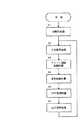
図2は、本発明に係る無人ヘリコプタの制御系ブロック図である。また、図3は、コントローラによる制御演算処理のフローチャートである。
【0025】
地上側の送信機21の操作による操縦指令信号が機体側の受信機8で受信されコントローラ9に送られて信号処理される。コントローラ9は、内部の制御回路28内で予め設定された制御プログラムにしたがって、図3に示すフローの演算処理を行う。
【0026】
まず、運転状態のフラグ等を初期値にセットする(ステップA1)。続いて入力信号処理部29で入力信号処理を行う(ステップA2)。これは、指令信号や各種センサの検出信号等の入力信号に基づいて受信状態が正常かどうか及び各種センサ類が正常かどうかをチェックするものである。
【0027】
次にエンジン回転制御計算を行う(ステップA3)。これは、エンジン回転制御計算部30で、送信機21のエンコン操作子23(図1)によるエンコンサーボ指令に基づいてスロットル開度を制御し所定のエンジン回転数で飛行するように制御するものである。
【0028】
次に姿勢制御計算を行う(ステップA4)。これは姿勢制御計算部31で、姿勢センサ12からの信号に基づいて機体の前後及び左右方向の傾斜を制御するものである。
【0029】
次にGPS制御計算を行う(ステップA5)。これはGPS制御計算部32で、GPSセンサ10からの信号に基づいて飛行位置及び飛行速度を制御するものである。
【0030】
次にこれらの入力信号処理及び各制御計算処理を行った後、出力信号処理部33から処理結果を出力する(ステップA6)。この出力信号により、エンジンの点火系を駆動して指令されたエンジン回転数に基づいてエンジンを駆動するとともに、各サーボモータ16〜20を駆動して方向や姿勢を制御する。
【0031】
これらのステップA1〜A6のルーチンは、飛行中例えば20ms程度ごとに繰り返されてデータを更新しながら制御される。
【0032】
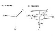
図4は、本発明に係る姿勢制御回路の構成図である。図5は、地球座標系と機体座標系の説明図である。
【0033】
姿勢制御回路58に姿勢センサ(ジャイロセンサ)12(図1、図2)から加速度データ及び姿勢データが入力される。加速度データは、姿勢センサ12からの機体座標の加速度センサ出力であり、姿勢データは、姿勢センサ12からの地球座標のジャイロ姿勢出力である。加速度データは、座標変換回路54で地球座標に変換され、その後減算器55で重力成分が除かれ機体運動加速度データとなる。
【0034】
ここで、ジャイロ姿勢出力は、ロール角をθx、ピッチ角をθy、ヨー角をθzとすると、
【数1】
【0035】
また、加速度センサー出力及び慣性加速度は、
【数2】
【0036】
また、座標変換回路54での機体座標と地球座標の関係については、
【数3】
【0037】
方位を機体座標に固定すると、θz=0より、
【数4】
【0038】
したがって、
【数5】
【0039】
ハイブリッド姿勢角は、
【数6】
【0040】
図6は、本発明に係る姿勢制御回路でのハイブリッド姿勢角の計算過程のフローチャートである。
【0041】
ステップQ1:
加速度センサからのデータを取得する。これは前記(数2)の(A)を構成するデータである。
【0042】
ステップQ2:
機体加速度の計算をする。これは前記(数2)の(B)を構成するデータである。
【0043】
ステップQ3:
ジャイロ姿勢角のデータを取得する。これは前記(数1)を構成するデータである。
【0044】
ステップQ4:
離陸状態又は着陸状態のいずれかか否かを判別する。離陸又は着陸状態であればステップQ6に進み、いずれでもなければステップQ5に進む。
【0045】
ステップQ5:
機首を方向変更する状態か否かを判別する。方向変更であればステップQ6に進み、方向変更でなければステップQ7に進む。
【0046】
ステップQ6:
ローパスフィルタ56(図4)及びハイパスフィルタ57(図4)の時定数TをT1に設定する。
【0047】
ステップQ7:
ローパスフィルタ56(図4)及びハイパスフィルタ57(図4)の時定数TをT2に設定する。T1<T2 である。
【0048】
ステップQ8:
時定数TをT1又はT2として前述の図4の回路の出力であるハイブリッド姿勢角を計算する。これは、上記(数6)に示すロール角及びピッチ角について演算するものである。この場合、予めT1 <T2 と設定しておくことにより、離着陸又は機首方向変更の場合には、時定数T=T1(ステップQ6)を小さくして、ステップQ8の式から分かるように、姿勢データの割合を小さく加速度データの割合を多くすることができる。また、離着陸又は機首方向変更のいずれでもない場合(通常飛行時)には、時定数T=T2(ステップQ7)を大きくして、姿勢データの割合を多くし加速度データの割合を少なくすることができる。
【0049】
これにより、離着陸又は機首方向変更のように原点姿勢角が大きく変わる可能性のある飛行状態では、主として加速度データに基づくハイブリッド姿勢角により急激な原点姿勢角の変化に追従することができる。
【0050】
また、風の外乱により機体が影響を受けて傾く場合にも、これを判別してステップQ6で時定数TをT1 として主として加速度データに基づく制御を行うようにしてもよい。さらに、ペイロードを検出してこれに応じて時定数を選択してもよい。
【0051】
一方、通常の飛行状態では、加速度データの割合を小さくしたハイブリッド姿勢角により、速度を減速しやすくして操縦の安定性を確保することができる。
【0052】
【発明の効果】
以上説明したように、本発明では、慣性加速度データと姿勢データとを組合わせたハイブリッド姿勢角に基づいて姿勢制御を行うため、機体の姿勢にかかわらずハイブリッド姿勢角の0点が常に姿勢角中立位置である制御原点となり、ホバリングの制御がしやすくなる。
【0053】
また、ローパスフィルタを通した加速度データとハイパスフィルタを通した姿勢データとの出力の割合を飛行状態に応じて変えるため、原点姿勢角が急激に変化する状況では加速度データの割合を多くしたハイブリッド姿勢角に基づいて制御し、通常の飛行状態では加速度データの割合を減らして制御することにより、加速度制御による減速のしにくさを伴うことなく、あらゆる飛行状態で安定して機体の姿勢を制御することができる。
【図面の簡単な説明】
【図1】本発明に係る無人ヘリコプタの構成図。
【図2】本発明に係る無人ヘリコプタの制御系ブロック図。
【図3】コントローラによる制御演算処理のフローチャート。
【図4】本発明に係る姿勢角制御計算回路の構成図。
【図5】地球座標系と機体座標系の説明図。
【図6】本発明に係る姿勢制御方法のフローチャート。
【符号の説明】
1:機体、2:メインロータ、3:ラダー、4:エンジン、5:点火系、
6:受信アンテナ、7:受信ボックス、8:受信機、9:コントローラ、
10:GPSセンサ、11:GPS表示灯、12:姿勢センサ、
13:GPSアンテナ、14:方位センサ、15:エンジン回転センサ、
16:右エルロンサーボモータ、17:左エルロンサーボモータ、
18:エレベーションサーボモータ、19:エンコンサーボモータ、
20:ラダーサーボモータ、21:送信機、22:第1操作子、
23:第2操作子、24:操作位置センサ、25:パネル表示部、
26:警告灯、27:テール、28:制御回路、54:座標変換回路、
55:減算器、56:ローパスフィルタ、57:ハイパスフィルタ、
58:姿勢制御回路。[0001]
TECHNICAL FIELD OF THE INVENTION
The present invention relates to an unmanned helicopter attitude control method using a gyro sensor.
[0002]
[Prior art]
An attitude control device for a flying object using an acceleration sensor is described in
[0003]
Θx = αy / g, Θy = -αx / g (g is gravitational acceleration)
Is controlled so that the attitude angle coincides with the target attitude angle. This makes it possible to cancel out the influence of the tail rotor and the influence of wind disturbance. This is because the acceleration in the earth coordinate system in which the azimuth of the body in the front-rear and left-right directions is fixed to the body axis becomes zero.
[0004]
However, in the attitude control device of
[0005]
[Patent Document 1]
Japanese Patent No. 3189027
[Problems to be solved by the invention]
An object of the present invention is to provide an attitude control method for an unmanned helicopter that can stably control the attitude even when the attitude angle changes due to a payload or wind disturbance regardless of the flight state, in consideration of the above-described conventional technology. And
[0007]
[Means for Solving the Problems]
In order to achieve the above object, the present invention provides an attitude control method for an unmanned helicopter using acceleration data and attitude data output from a gyro sensor, wherein the acceleration data is coordinate-transformed to inertial acceleration data in an earth coordinate system. The inertial acceleration data is input to a low-pass filter, the attitude data is input to a high-pass filter, and the output of the low-pass filter and the output of the high-pass filter are mixed to create a hybrid attitude angle. An attitude control method for an unmanned helicopter, wherein the attitude control of an airframe is performed based on the attitude control method.
[0008]
According to this configuration, the attitude control is performed based on the hybrid attitude angle obtained by combining the inertial acceleration data (the low frequency component passed through the low pass filter) and the attitude data (the high frequency component passed through the high pass filter). Regardless of the posture, the zero point of the hybrid posture angle is always the control origin (hereinafter referred to as the origin posture angle), which is the neutral position of the posture angle, and hovering is easily controlled. That is, the origin attitude angle at which hovering can be performed differs depending on the payload (load loaded by the main rotor) and the wind direction. For example, as the payload increases, the required thrust of the main rotor increases, and the thrust of the tail rotor also increases. Accordingly, it is necessary to incline the main rotor in such a direction as to cancel this, thereby inclining the original attitude angle. Similarly, if there is a wind disturbance, the origin posture angle is inclined in the opposite direction so as to cancel the disturbance.
[0009]
However, according to the hybrid attitude angle, the hovering control can be performed very easily because the zero point position becomes the neutral position of the attitude angle in any flying state.
[0010]
In a preferred configuration example, the ratio of the output of the low-pass filter to the output of the high-pass filter is changed according to the flight condition.
[0011]
According to this configuration, the ratio of the output of the acceleration data that has passed through the low-pass filter and the output of the posture data that has passed through the high-pass filter is changed according to the flight condition. By controlling based on the increased hybrid attitude angle and controlling by reducing the proportion of acceleration data in normal flight conditions, the aircraft is stable in all flight conditions without difficulty in deceleration by acceleration control. The attitude can be controlled.
[0012]
In a preferred configuration example, a takeoff / landing state and an azimuth change state are determined as the flight state.
[0013]
According to this configuration, in the take-off / landing state and the azimuth change state in which the origin attitude angle of the aircraft greatly changes, the attitude attitude is stabilized by moving the hybrid attitude angle to the acceleration data side and responding to the sudden change in the origin attitude angle. It can be carried out.
[0014]
In a preferred configuration example, the ratio of the output is changed by changing the time constant of the low-pass filter and the high-pass filter.
[0015]
According to this configuration, the output values from the low-pass filter and the high-pass filter can be changed by changing the time constant of the filter, and the rate of acceleration control can be easily changed.
[0016]
BEST MODE FOR CARRYING OUT THE INVENTION
FIG. 1 is a configuration diagram of an unmanned helicopter according to an embodiment of the present invention.
The
[0017]
The
[0018]
The
[0019]
[0020]
The first operator 22 is for elevator operation and rudder operation. By operating the first operator 22 in the ab direction, the
[0021]
The
[0022]
By operating the
[0023]
The
[0024]
FIG. 2 is a control system block diagram of the unmanned helicopter according to the present invention. FIG. 3 is a flowchart of a control calculation process by the controller.
[0025]
A control command signal by the operation of the
[0026]
First, an operation state flag and the like are set to initial values (step A1). Subsequently, input signal processing is performed by the input signal processing unit 29 (step A2). This is to check whether the reception state is normal and whether various sensors are normal based on input signals such as command signals and detection signals of various sensors.
[0027]
Next, an engine rotation control calculation is performed (step A3). In this, the engine rotation
[0028]
Next, a posture control calculation is performed (step A4). This is to control the inclination of the body in the front-back and left-right directions based on the signal from the
[0029]
Next, GPS control calculation is performed (step A5). This is to control the flight position and the flight speed based on the signal from the
[0030]
Next, after performing these input signal processing and each control calculation processing, the processing result is output from the output signal processing unit 33 (step A6). Based on the output signal, the ignition system of the engine is driven to drive the engine based on the commanded engine speed, and the
[0031]
The routine of these steps A1 to A6 is controlled while the data is being updated during flight, for example, about every 20 ms.
[0032]
FIG. 4 is a configuration diagram of the attitude control circuit according to the present invention. FIG. 5 is an explanatory diagram of the earth coordinate system and the body coordinate system.
[0033]
The acceleration data and the attitude data are input to the
[0034]
Here, the gyro posture output is as follows, assuming that the roll angle is θx, the pitch angle is θy, and the yaw angle is θz.
(Equation 1)
[0035]
The acceleration sensor output and inertial acceleration are
(Equation 2)
[0036]
Regarding the relationship between the body coordinates and the earth coordinates in the coordinate
[Equation 3]
[0037]
When the direction is fixed to the body coordinates, from θz = 0,
(Equation 4)
[0038]
Therefore,
(Equation 5)
[0039]
The hybrid attitude angle is
(Equation 6)
[0040]
FIG. 6 is a flowchart of a process of calculating a hybrid attitude angle in the attitude control circuit according to the present invention.
[0041]
Step Q1:
Obtain data from the acceleration sensor. This is the data that constitutes (A) in (Equation 2).
[0042]
Step Q2:
Calculate the aircraft acceleration. This is the data that constitutes (B) of (Equation 2).
[0043]
Step Q3:
Obtain gyro attitude angle data. This is data constituting the above (Equation 1).
[0044]
Step Q4:
It is determined whether it is in a takeoff state or a landing state. If it is in the takeoff or landing state, the process proceeds to step Q6; otherwise, the process proceeds to step Q5.
[0045]
Step Q5:
It is determined whether or not the nose is to change direction. If the direction is changed, the process proceeds to step Q6. If the direction is not changed, the process proceeds to step Q7.
[0046]
Step Q6:
The time constant T of the low-pass filter 56 (FIG. 4) and the high-pass filter 57 (FIG. 4) is set to T1.
[0047]
Step Q7:
The time constant T of the low-pass filter 56 (FIG. 4) and the high-pass filter 57 (FIG. 4) is set to T2. T1 <T2.
[0048]
Step Q8:
Assuming that the time constant T is T1 or T2, the hybrid attitude angle which is the output of the circuit of FIG. 4 is calculated. This is for calculating the roll angle and the pitch angle shown in the above (Equation 6). In this case, by setting T1 <T2 in advance, in the case of takeoff / landing or changing the nose direction, the time constant T = T1 (step Q6) is reduced, and as can be seen from the equation of step Q8, the attitude is changed. The ratio of data can be reduced and the ratio of acceleration data can be increased. In addition, when neither the takeoff and landing nor the nose direction change is performed (during normal flight), the time constant T = T2 (step Q7) is increased to increase the proportion of the attitude data and decrease the proportion of the acceleration data. Can be.
[0049]
As a result, in a flight state in which the origin attitude angle may greatly change such as takeoff and landing or a change in the nose direction, it is possible to follow a sudden change in the origin attitude angle mainly by the hybrid attitude angle based on the acceleration data.
[0050]
Further, even when the airframe is tilted due to the influence of the wind disturbance, the control may be performed based on the acceleration data with the time constant T set to T1 in step Q6. Further, the payload may be detected, and the time constant may be selected accordingly.
[0051]
On the other hand, in a normal flight state, the hybrid attitude angle in which the proportion of the acceleration data is reduced makes it possible to easily reduce the speed and ensure the stability of the steering.
[0052]
【The invention's effect】
As described above, in the present invention, since the attitude control is performed based on the hybrid attitude angle obtained by combining the inertial acceleration data and the attitude data, the zero point of the hybrid attitude angle is always the attitude angle neutral regardless of the attitude of the aircraft. It becomes a control origin, which is a position, and hovering control becomes easy.
[0053]
In addition, since the ratio of the output of the acceleration data that has passed through the low-pass filter and the attitude data that has passed through the high-pass filter changes according to the flight conditions, the hybrid attitude has a large percentage of acceleration data when the origin attitude angle changes rapidly. By controlling based on the angle and reducing the ratio of acceleration data in normal flight conditions, the aircraft attitude can be controlled stably in all flight conditions without the difficulty of deceleration due to acceleration control. be able to.
[Brief description of the drawings]
FIG. 1 is a configuration diagram of an unmanned helicopter according to the present invention.
FIG. 2 is a control system block diagram of the unmanned helicopter according to the present invention.
FIG. 3 is a flowchart of a control calculation process performed by a controller.
FIG. 4 is a configuration diagram of an attitude angle control calculation circuit according to the present invention.
FIG. 5 is an explanatory diagram of an earth coordinate system and an airframe coordinate system.
FIG. 6 is a flowchart of a posture control method according to the present invention.
[Explanation of symbols]
1: Airframe, 2: Main rotor, 3: Rudder, 4: Engine, 5: Ignition system,
6: receiving antenna, 7: receiving box, 8: receiver, 9: controller,
10: GPS sensor, 11: GPS indicator light, 12: Attitude sensor,
13: GPS antenna, 14: bearing sensor, 15: engine rotation sensor,
16: right aileron servomotor, 17: left aileron servomotor,
18: Elevation servo motor, 19: Encon servo motor,
20: ladder servomotor, 21: transmitter, 22: first operator,
23: second operation element, 24: operation position sensor, 25: panel display unit,
26: warning light, 27: tail, 28: control circuit, 54: coordinate conversion circuit,
55: subtractor, 56: low-pass filter, 57: high-pass filter,
58: attitude control circuit.
Claims (4)
Translated fromJapanese前記加速度データを座標変換して地球座標系の慣性加速度データとし、
この慣性加速度データをローパスフィルタに入力し、
前記姿勢データをハイパスフィルタに入力し、
前記ローパスフィルタの出力及び前記ハイパスフィルタの出力をミキシングしてハイブリッド姿勢角を作成し、
このハイブリッド姿勢角に基づいて機体の姿勢制御を行うことを特徴とする無人ヘリコプタの姿勢制御方法。An attitude control method for an unmanned helicopter using acceleration data and attitude data output from a gyro sensor,
The acceleration data is coordinate-transformed into inertial acceleration data in the earth coordinate system,
This inertial acceleration data is input to the low-pass filter,
Inputting the attitude data to a high-pass filter,
Mixing the output of the low-pass filter and the output of the high-pass filter to create a hybrid attitude angle,
An attitude control method for an unmanned helicopter, wherein the attitude control of the airframe is performed based on the hybrid attitude angle.
Priority Applications (1)
| Application Number | Priority Date | Filing Date | Title |
|---|---|---|---|
| JP2003062329AJP2004268730A (en) | 2003-03-07 | 2003-03-07 | Attitude control method for unmanned helicopter |
Applications Claiming Priority (1)
| Application Number | Priority Date | Filing Date | Title |
|---|---|---|---|
| JP2003062329AJP2004268730A (en) | 2003-03-07 | 2003-03-07 | Attitude control method for unmanned helicopter |
Publications (1)
| Publication Number | Publication Date |
|---|---|
| JP2004268730Atrue JP2004268730A (en) | 2004-09-30 |
Family
ID=33124280
Family Applications (1)
| Application Number | Title | Priority Date | Filing Date |
|---|---|---|---|
| JP2003062329APendingJP2004268730A (en) | 2003-03-07 | 2003-03-07 | Attitude control method for unmanned helicopter |
Country Status (1)
| Country | Link |
|---|---|
| JP (1) | JP2004268730A (en) |
Cited By (21)
| Publication number | Priority date | Publication date | Assignee | Title |
|---|---|---|---|---|
| WO2007015138A1 (en)* | 2005-08-01 | 2007-02-08 | Toyota Jidosha Kabushiki Kaisha | Correction device for acceleration sensor, and output value correction method for acceleration sensor |
| WO2007015136A1 (en)* | 2005-08-01 | 2007-02-08 | Toyota Jidosha Kabusiki Kaisha | Robot control system and control method for robot |
| JP2008256381A (en)* | 2007-03-30 | 2008-10-23 | Nec Corp | Attitude angle measuring instrument and attitude angle measuring method used for that attitude angle measuring instrument |
| US7949487B2 (en) | 2005-08-01 | 2011-05-24 | Toyota Jidosha Kabushiki Kaisha | Moving body posture angle detecting apparatus |
| WO2011072362A1 (en)* | 2009-12-18 | 2011-06-23 | National Research Council Of Canada | Response mode for control system of piloted craft |
| US8001839B2 (en) | 2005-08-01 | 2011-08-23 | Toyota Jidosha Kabushiki Kaisha | Sensor unit |
| KR101246046B1 (en) | 2011-06-29 | 2013-03-26 | (주)시스윈일렉트로닉스 | Safe Landing Apparatus And Method Of Unmanned Flight Robot |
| WO2014014072A1 (en)* | 2012-07-20 | 2014-01-23 | ヤマハ発動機株式会社 | Unmanned helicopter |
| CN104102128A (en)* | 2013-04-09 | 2014-10-15 | 中国人民解放军第二炮兵工程大学 | Anti-interference attitude control method suitable for miniaturized unmanned aircraft |
| CN104536462A (en)* | 2015-01-09 | 2015-04-22 | 西安应用光学研究所 | Position control method based on fiber-optic gyroscope integral means |
| CN104670496A (en)* | 2015-03-11 | 2015-06-03 | 西南大学 | Six-shaft type pesticide spray flight device and control method |
| CN105182989A (en)* | 2015-09-25 | 2015-12-23 | 北京航空航天大学 | A method of aircraft attitude control under the influence of wind field |
| WO2018058311A1 (en)* | 2016-09-27 | 2018-04-05 | 深圳市大疆创新科技有限公司 | Control method, control device, and electronic device |
| JPWO2017208281A1 (en)* | 2016-06-01 | 2018-06-14 | 株式会社 スカイロボット | Wave detection type search system |
| WO2018110598A1 (en)* | 2016-12-13 | 2018-06-21 | 株式会社自律制御システム研究所 | Unmanned aircraft, device for controlling unmanned aircraft, method for controlling unmanned aircraft, and device for detecting failure of unmanned aircraft |
| US10095226B1 (en) | 2008-02-12 | 2018-10-09 | Drone-Control, Llc | Radio controlled aircraft, remote controller and methods for use therewith |
| WO2019006771A1 (en)* | 2017-07-06 | 2019-01-10 | 杨顺伟 | External force interference resistance method and device for unmanned aerial vehicle |
| US10717525B2 (en) | 2013-06-25 | 2020-07-21 | SZ DJI Technology Co., Ltd. | Aircraft control apparatus, control system and control method |
| CN112462793A (en)* | 2019-09-09 | 2021-03-09 | 顺丰科技有限公司 | Sensor-based equipment control method and device and computer equipment |
| US11260973B2 (en) | 2013-06-25 | 2022-03-01 | SZ DJI Technology Co., Ltd. | Aircraft control apparatus, control system and control method |
| US11385059B2 (en) | 2017-05-26 | 2022-07-12 | Guangzhou Xaircraft Technology Co., Ltd | Method for determining heading of unmanned aerial vehicle and unmanned aerial vehicle |
- 2003
- 2003-03-07JPJP2003062329Apatent/JP2004268730A/enactivePending
Cited By (33)
| Publication number | Priority date | Publication date | Assignee | Title |
|---|---|---|---|---|
| WO2007015136A1 (en)* | 2005-08-01 | 2007-02-08 | Toyota Jidosha Kabusiki Kaisha | Robot control system and control method for robot |
| CN101233460B (en)* | 2005-08-01 | 2010-10-06 | 丰田自动车株式会社 | Robot control system and control method for robot |
| US7949487B2 (en) | 2005-08-01 | 2011-05-24 | Toyota Jidosha Kabushiki Kaisha | Moving body posture angle detecting apparatus |
| US8001839B2 (en) | 2005-08-01 | 2011-08-23 | Toyota Jidosha Kabushiki Kaisha | Sensor unit |
| WO2007015138A1 (en)* | 2005-08-01 | 2007-02-08 | Toyota Jidosha Kabushiki Kaisha | Correction device for acceleration sensor, and output value correction method for acceleration sensor |
| JP2008256381A (en)* | 2007-03-30 | 2008-10-23 | Nec Corp | Attitude angle measuring instrument and attitude angle measuring method used for that attitude angle measuring instrument |
| US10095226B1 (en) | 2008-02-12 | 2018-10-09 | Drone-Control, Llc | Radio controlled aircraft, remote controller and methods for use therewith |
| US11281205B2 (en) | 2008-02-12 | 2022-03-22 | Drone-Control, Llc | Radio controlled aircraft, remote controller and methods for use therewith |
| US10248117B2 (en) | 2008-02-12 | 2019-04-02 | Drone-Control, Llc | Radio controlled aircraft, remote controller and methods for use therewith |
| JP2013514215A (en)* | 2009-12-18 | 2013-04-25 | ナショナル リサーチ カウンシル オブ カナダ | Response mode for control system of maneuvered craft |
| US8688295B2 (en) | 2009-12-18 | 2014-04-01 | National Research Council Of Canada | Response mode for control system of piloted craft |
| WO2011072362A1 (en)* | 2009-12-18 | 2011-06-23 | National Research Council Of Canada | Response mode for control system of piloted craft |
| KR101246046B1 (en) | 2011-06-29 | 2013-03-26 | (주)시스윈일렉트로닉스 | Safe Landing Apparatus And Method Of Unmanned Flight Robot |
| JP2014019357A (en)* | 2012-07-20 | 2014-02-03 | Yamaha Motor Co Ltd | Unmanned helicopter |
| CN104470803A (en)* | 2012-07-20 | 2015-03-25 | 雅马哈发动机株式会社 | Unmanned helicopter |
| WO2014014072A1 (en)* | 2012-07-20 | 2014-01-23 | ヤマハ発動機株式会社 | Unmanned helicopter |
| US9382012B2 (en) | 2012-07-20 | 2016-07-05 | Yamaha Hatsudoki Kabushiki Kaisha | Unmanned helicopter |
| CN104102128A (en)* | 2013-04-09 | 2014-10-15 | 中国人民解放军第二炮兵工程大学 | Anti-interference attitude control method suitable for miniaturized unmanned aircraft |
| US11801938B2 (en) | 2013-06-25 | 2023-10-31 | SZ DJI Technology Co., Ltd | Aircraft control apparatus, control system and control method |
| US10717525B2 (en) | 2013-06-25 | 2020-07-21 | SZ DJI Technology Co., Ltd. | Aircraft control apparatus, control system and control method |
| US11260973B2 (en) | 2013-06-25 | 2022-03-01 | SZ DJI Technology Co., Ltd. | Aircraft control apparatus, control system and control method |
| CN104536462A (en)* | 2015-01-09 | 2015-04-22 | 西安应用光学研究所 | Position control method based on fiber-optic gyroscope integral means |
| CN104670496A (en)* | 2015-03-11 | 2015-06-03 | 西南大学 | Six-shaft type pesticide spray flight device and control method |
| CN105182989B (en)* | 2015-09-25 | 2018-01-19 | 北京航空航天大学 | A kind of aspect control method under the influence of wind field |
| CN105182989A (en)* | 2015-09-25 | 2015-12-23 | 北京航空航天大学 | A method of aircraft attitude control under the influence of wind field |
| JPWO2017208281A1 (en)* | 2016-06-01 | 2018-06-14 | 株式会社 スカイロボット | Wave detection type search system |
| WO2018058311A1 (en)* | 2016-09-27 | 2018-04-05 | 深圳市大疆创新科技有限公司 | Control method, control device, and electronic device |
| JPWO2018110598A1 (en)* | 2016-12-13 | 2020-01-09 | 株式会社自律制御システム研究所 | Unmanned aerial vehicle, unmanned aerial vehicle control device, unmanned aerial vehicle control method, and unmanned aerial vehicle failure detection device |
| WO2018110598A1 (en)* | 2016-12-13 | 2018-06-21 | 株式会社自律制御システム研究所 | Unmanned aircraft, device for controlling unmanned aircraft, method for controlling unmanned aircraft, and device for detecting failure of unmanned aircraft |
| US11640178B2 (en) | 2016-12-13 | 2023-05-02 | Acsl Ltd. | Unmanned aircraft, device for controlling unmanned aircraft, method for controlling unmanned aircraft, and device for detecting failure of unmanned aircraft |
| US11385059B2 (en) | 2017-05-26 | 2022-07-12 | Guangzhou Xaircraft Technology Co., Ltd | Method for determining heading of unmanned aerial vehicle and unmanned aerial vehicle |
| WO2019006771A1 (en)* | 2017-07-06 | 2019-01-10 | 杨顺伟 | External force interference resistance method and device for unmanned aerial vehicle |
| CN112462793A (en)* | 2019-09-09 | 2021-03-09 | 顺丰科技有限公司 | Sensor-based equipment control method and device and computer equipment |
Similar Documents
| Publication | Publication Date | Title |
|---|---|---|
| JP2004268730A (en) | Attitude control method for unmanned helicopter | |
| CN104335128B (en) | Method for controlling multirotor rotorcraft with crosswind and accelerometer bias estimation and compensation | |
| JP4109767B2 (en) | Unmanned helicopter flight control system. | |
| CN107703972A (en) | The particularly flying wing type fixed-wing unmanned plane with automatic Pilot is driven with auxiliary hand-operating | |
| US12099128B2 (en) | Methods and systems for utilizing dual global positioning system (GPS) antennas in vertical take-off and landing (VTOL) aerial vehicles | |
| JP2009143268A (en) | Flight control system for aircraft and aircraft with the flight control system | |
| JP2001306144A (en) | Unmanned helicopter flight control system. | |
| JP2001306143A (en) | Flight control system for unmanned helicopter | |
| JPH0848297A (en) | Unmanned helicopter remote flight control system | |
| JP2016215958A (en) | Multicopter and multicopter system | |
| JP4130598B2 (en) | GPS control method for unmanned helicopter | |
| JP2008201183A (en) | Attitude control device | |
| JP4316772B2 (en) | Moving body | |
| JP3189027B2 (en) | Aircraft attitude control device | |
| JP4084215B2 (en) | Control method of unmanned helicopter | |
| JP4157397B2 (en) | Speed calculation circuit for moving body and moving body | |
| US11267566B2 (en) | Flying object control device, flying object, and program | |
| CN118034328A (en) | Rotor unmanned aerial vehicle control method based on lift force feedback power device | |
| US11592840B2 (en) | Driving control device for remote controlled helicopter | |
| KR102260716B1 (en) | Multicopter Yawing Control System | |
| JP2001301695A (en) | Flight control system for unmanned helicopter | |
| JPH07246999A (en) | Attitude control device for unmanned helicopter | |
| WO2022080232A1 (en) | Flying body | |
| JP2009096369A (en) | Maneuvering support device for unmanned radio helicopter | |
| JP4084214B2 (en) | Engine rotation control method of unmanned helicopter |
Legal Events
| Date | Code | Title | Description |
|---|---|---|---|
| A621 | Written request for application examination | Free format text:JAPANESE INTERMEDIATE CODE: A621 Effective date:20060209 | |
| A521 | Request for written amendment filed | Free format text:JAPANESE INTERMEDIATE CODE: A821 Effective date:20060411 | |
| RD02 | Notification of acceptance of power of attorney | Free format text:JAPANESE INTERMEDIATE CODE: A7422 Effective date:20060411 | |
| A977 | Report on retrieval | Free format text:JAPANESE INTERMEDIATE CODE: A971007 Effective date:20070905 | |
| A131 | Notification of reasons for refusal | Free format text:JAPANESE INTERMEDIATE CODE: A131 Effective date:20070918 | |
| A521 | Request for written amendment filed | Free format text:JAPANESE INTERMEDIATE CODE: A523 Effective date:20071119 | |
| A02 | Decision of refusal | Free format text:JAPANESE INTERMEDIATE CODE: A02 Effective date:20080219 |