Movatterモバイル変換


[0]ホーム

URL:


JP2004267217A - Method and apparatus for extermination of noxious insect - Google Patents

Method and apparatus for extermination of noxious insect
Download PDF

Info

Publication number
JP2004267217A
JP2004267217AJP2004133789AJP2004133789AJP2004267217AJP 2004267217 AJP2004267217 AJP 2004267217AJP 2004133789 AJP2004133789 AJP 2004133789AJP 2004133789 AJP2004133789 AJP 2004133789AJP 2004267217 AJP2004267217 AJP 2004267217A
Authority
JP
Japan
Prior art keywords
pest control
pest
control device
bait
control devices
Prior art date
Legal status (The legal status is an assumption and is not a legal conclusion. Google has not performed a legal analysis and makes no representation as to the accuracy of the status listed.)
Pending
Application number
JP2004133789A
Other languages
Japanese (ja)
Other versions
JP2004267217A5 (en
Inventor
Daniel T Barber
バーバー,ダニエル・ティー
Anton Arnoldy
アーノルディー,アントン
Stanley Michael Gorgacz
ゴーガクツ,スタンリー・マイケル
James Edward King
キング,ジェイムズ・エドワード
A Sterett Robertson
ロバートソン,エイ・スタレット
Mick A Trompen
トロンペン,ミック・エイ
Malcom Warren
ウォーレン,マルコム
Dennis Wujek
ウジェク,デニス
Scott Ray
レイ,スコット
Current Assignee (The listed assignees may be inaccurate. Google has not performed a legal analysis and makes no representation or warranty as to the accuracy of the list.)
Corteva Agriscience LLC
Original Assignee
Dow AgroSciences LLC
Priority date (The priority date is an assumption and is not a legal conclusion. Google has not performed a legal analysis and makes no representation as to the accuracy of the date listed.)
Filing date
Publication date
Application filed by Dow AgroSciences LLCfiledCriticalDow AgroSciences LLC
Priority to JP2004133789ApriorityCriticalpatent/JP2004267217A/en
Publication of JP2004267217ApublicationCriticalpatent/JP2004267217A/en
Publication of JP2004267217A5publicationCriticalpatent/JP2004267217A5/ja
Pendinglegal-statusCriticalCurrent

Links

Images

Landscapes

Abstract

<P>PROBLEM TO BE SOLVED: To provide a system for simply and surely performing detection of position of a termite exterminater embeded underground and appearance of termites. <P>SOLUTION: The pest control system 20 has pest control devices 110 set around a region or building 22. The devices 110 have bait elements and communication lines. The communication lines have a form of a passive RF tag transmitting information indicating a bait condition and the specific indication of each pest control device. A potable detector 30 for detecting the positions of the pest control devices 110 through the communication lines and connectable with the pest control device 110 is provided. A data collection device 40 collecting data collected from the pest control devices 110 can be substitutionally or additionally utilized. The bait element may have a magnetic component element so as to give magnetic marks indicating bait-consuming behavior of the objective kind of noxious insects. The devices, if necessary, have one or more environmental sensors indicating and predicting behavior of the noxious insects. <P>COPYRIGHT: (C)2004,JPO&NCIPI

Description

Translated fromJapanese

本発明は、害虫駆除技術、より具体的に且つ非限定的には、1つ又は2つ以上の種類の害虫から保護すべき領域の周りにて隔てられた多数の害虫駆除装置からデータを収集する技術に関する。  The present invention relates to pest control technology, more specifically and without limitation, collecting data from multiple pest control devices separated around the area to be protected from one or more types of pests. Related to technology.

地中シロアリは、木製構造体に甚大な損害を与える可能性のある、特に問題となる種類の害虫である。シロアリを除去し且つ昆虫及び非昆虫の種類の双方のその他の有害な害虫を除去するため色々な方法が提案されている。1つの方法において、害虫駆除は、保護すべき領域内に化学的殺虫剤を全体的に施すことによるものである。しかし、環境的規制の結果、この方法は、望ましくないものとなりつつある。  Underground termites are a particularly problematic type of pest that can cause significant damage to wooden structures. Various methods have been proposed to remove termites and other harmful pests of both insect and non-insect types. In one method, pest control is by applying a chemical pesticide entirely within the area to be protected. However, as a result of environmental regulations, this method is becoming undesirable.

最近、殺虫化学薬剤を目標に向けて集中的に供給することを可能にすべく改良が為されている。スーの米国特許第5,815,090号はその一例である。シロアリの駆除を目的とする別の例は、インディアナ州、インディアナポリス、9330ジオンヴァイルロードに本社があるダウ・アグロサイエンスズのセントリコン(SENTRICON)(登録商標名)システムである。このシステムにおいて、各々がシロアリの食用材料を有する多数の装置を保護すべき住宅の周りの地中に配置する。これらの装置は、害虫駆除サービス員がシロアリの有無について日常的に検査し、各装置と関係した特徴的なバーコードラベルを基準にして検査データを記録する。所定の装置内にシロアリが発見されたならば、シロアリの巣に持ち帰ってその群体を全滅させることを目的とする遅速効果のある殺虫剤を保持する餌を配置する。
米国特許第5,815,090号
Recently, improvements have been made to allow targeted delivery of pesticidal chemicals. Sue, U.S. Pat. No. 5,815,090 is one example. Another example intended for termite control is the SENTTRICON® system of Dow Agrosciences, headquartered at 9330 Zionville Road, Indianapolis, Indiana. In this system, multiple devices, each containing termite edible material, are placed underground around the home to be protected. In these devices, pest control service personnel routinely inspect for the presence of termites and record the inspection data based on the characteristic barcode label associated with each device. Once termites are found in a given device, baits carrying slow-acting pesticides intended to be brought back to termite nests and annihilated the colony are placed.
U.S. Pat. No. 5,815,090

不都合なことに、これらの装置は、配置後、その位置を探知することが難しいことがしばしばあり、その結果、検査作業に過剰な時間を消費することになる。金属製装置の場合、それら装置の位置探知を速くするため、金属製の検知装置が利用されることがある。しかし、このようにして、装置を検知することを妨げるであろう、非常に多数の金属物が家及びその他の構造体の周りに埋め込まれている。更に、装置を金属検知装置にて容易に検知することができない程度までそれら装置を非金属材料にて製造することが望ましいことが
更に、害虫の活動に関するデータを収集するための代替的な技術も望まれる。例えば、害虫駆除サービスによりデータを収集するのに必要な時間を短くすることが望ましい。また、データを収集する技術の信頼性を高め且つより広汎な害虫の活動データを得ることも望ましい。
Unfortunately, these devices are often difficult to locate after deployment, resulting in excessive time spent on inspection work. In the case of metal devices, metal detectors may be used to speed the location of those devices. However, in this way, a large number of metal objects are embedded around the house and other structures that would prevent the device from being detected. In addition, it is desirable to manufacture devices from non-metallic materials to the extent that they cannot be easily detected by metal detectors.Also, alternative techniques for collecting data on pest activity are desired. For example, it is desirable to reduce the time required to collect data with a pest control service. It is also desirable to increase the reliability of data collection techniques and to obtain more extensive pest activity data.

本発明の1つの形態は、特徴的な害虫駆除技術を含む。別の形態において、選んだ1つ又は2つ以上の害虫の種を検知し且つ全滅させるための特徴的な害虫駆除装置が提供される。本明細書で使用するように、「害虫駆除装置」とは、広く、1つ又は2つ以上の種の害虫を感知し、検知し、監視し、餌でおびき寄せ、給餌し、毒を与え、すなわち全滅させるために使用される任意の装置を広く意味するものとする。更に別の形態において、特徴的な害虫駆除装置の位置を探知する技術が提供される。  One form of the present invention involves a characteristic pest control technique. In another aspect, a characteristic pest control device is provided for detecting and annihilating one or more selected pest species. As used herein, "pest control device" broadly refers to sensing, detecting, monitoring, lureing, feeding, poisoning one or more species of pests, That is, any device used for annihilation is meant broadly. In yet another aspect, a technique is provided for locating a characteristic pest control device.

本発明の更に別の形態は、特徴的な害虫駆除システムを含む。このシステムは、多数の害虫駆除装置と、害虫駆除装置からデータを収集する探知器とを含む。この探知器は、害虫駆除装置の各々と個々に無線通信を行い得る形態とされた携帯型の形態とすることができる。  Yet another aspect of the present invention includes a characteristic pest control system. The system includes a number of pest control devices and a detector that collects data from the pest control devices. The detector may be in a portable form that is capable of individually communicating wirelessly with each of the pest control devices.

本発明の別の形態は、励起信号に応答可能な受動型RF通信回路のような、特徴的な無線通信能力を備える害虫駆除装置を含む。この装置は、オプション的に、能動型の無線通信回路を含んでいる。  Another aspect of the invention includes a pest control device with characteristic wireless communication capabilities, such as a passive RF communication circuit responsive to an excitation signal. The device optionally includes an active wireless communication circuit.

本発明の害虫駆除装置の更に別型式のものは、装置を特徴的に識別する信号を提供する通信回路を含む。更に、この通信回路は、装置と関係した害虫の活動を示す信号を伝送することができる。  Yet another type of pest control device of the present invention includes a communication circuit that provides a signal that uniquely identifies the device. In addition, the communication circuit can transmit signals indicative of pest activity associated with the device.

本発明の1つの代替的な形態において、害虫駆除装置は、少なくとも一部分が磁気材料で出来た特徴的な監視餌を含む。更なる代替例において、害虫駆除装置は、1つ又は2つ以上の相応する環境の特徴に関するデータを収集するため1つ又は2つ以上の環境センサを含む。  In one alternative form of the invention, the pest control device includes a characteristic surveillance bait at least partially made of magnetic material. In a further alternative, the pest control device includes one or more environmental sensors to collect data on one or more corresponding environmental features.

本発明の追加的な形態、特徴、特色及び目的は、図面及び本明細書の説明から明らかになるであろう。  Additional aspects, features, features and objects of the present invention will become apparent from the drawings and description herein.

本発明の原理の理解を促進する目的にて、次に図面に図示した実施の形態に関して説明し、その説明のため特定の用語を使用する。しかし、これにより本発明の範囲を何ら限定することを意図するものではないことを理解すべきである。説明した実施の形態の任意の変更及び更なる改変例並びに本明細書に記載した本発明の原理の任意の更なる適用例は、本発明が関係する技術分野の当業者に通常、案出されるであろうと考えられる。  For the purposes of promoting an understanding of the principles of the invention, reference will now be made to the embodiments illustrated in the drawings and specific language will be used for the description. It should be understood, however, that this is not intended to limit the scope of the invention in any way. Any alterations and further modifications of the described embodiments, as well as any further applications of the principles of the invention described herein, will generally occur to those skilled in the art to which the invention pertains. It is considered that.

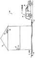
図1には、本発明の1つの実施の形態の害虫駆除システム20が図示されている。システム20は、地中シロアリのような害虫に起因する損害から建物22を保護し得るように配置されている。システム20は、建物22の周りに配置された多数の害虫駆除装置110を含む。図1において、明確化のため、幾つかの装置110のみが参照番号で特定的に表示してある。システム20は、また、装置110に関する情報を収集し得るように探知器30も含む。探知器30により装置110から収集されたデータは通信インターフェース部41を介してデータ収集装置(DCU)40内に収集される。  FIG. 1 illustrates apest control system 20 according to one embodiment of the present invention. Thesystem 20 is arranged to protect thebuilding 22 from damage caused by pests such as underground termites. Thesystem 20 includes a number ofpest control devices 110 located around abuilding 22. In FIG. 1, for the sake of clarity, only some of thedevices 110 are specifically indicated by reference numbers. Thesystem 20 also includes alocator 30 so that information about thedevice 110 can be collected. Data collected from thedevice 110 by thedetector 30 is collected in a data collection device (DCU) 40 via the communication interface unit 41.

図2を更に参照すると、システム20の作動の特定の特徴が図示されている。図2において、無線通信技術を使用して少なくとも一部分が地面G内に配置された害虫駆除装置110を探知するために探知器30を作動させる害虫駆除サービス員Pが図示されている。この例において、探知器30は、設置した装置110との無線通信を確立し得るように地面Gを掃引するのに便宜な携帯型の形態にて図示されている。システム20の追加的な特徴及びその作用は、図5及び図6に関して説明するが、図3及び図4の分解組立図を参照しつつ、1つの代表的な害虫駆除装置110に関する第一の更なる詳細について説明する。  With further reference to FIG. 2, certain features of the operation of thesystem 20 are illustrated. In FIG. 2, a pest control serviceman P is shown operating adetector 30 to detect apest control device 110 located at least partially within the ground G using wireless communication technology. In this example, thedetector 30 is shown in a portable form that is convenient for sweeping the ground G so that wireless communication with the installeddevice 110 can be established. Additional features of thesystem 20 and its operation will be described with respect to FIGS. 5 and 6, but with reference to the exploded views of FIGS. 3 and 4, a first update for one exemplarypest control device 110. Details will be described.

図3及び図4に示すように、害虫駆除装置110は、害虫の活動監視アセンブリ130を備えている。監視アセンブリ130は、各々が害虫の選択した1つ又は2つ以上の種に対する餌材料から出来た2つの餌部材132を含んでいる。例えば、餌部材132の各々は、かかる害虫の好む食物である材料から形成することができる。地中シロアリに関する一例において、餌部材132の各々は、殺虫剤成分を含まない柔軟な木ブロックの形態をしている。シロアリに対する他の例において、餌部材132は、最初に殺虫剤を含み、木以外の組成又はこれら特徴の組合せ体を備えている。害虫駆除装置110がシロアリ以外の種類の害虫を対象とする更に別の例において、餌部材132の相応して相違する組成が典型的に使用される。  As shown in FIGS. 3 and 4, thepest control device 110 includes a pestactivity monitoring assembly 130. Themonitoring assembly 130 includes twobait members 132, each made of bait material for one or more selected species of the pest. For example, each of thebait members 132 can be formed from a material that is a preferred food for such pests. In one example for an underground termite, each of thebait members 132 is in the form of a flexible wood block that does not include an insecticide component. In another example for termites, thebait member 132 initially includes an insecticide and comprises a non-wood composition or combination of these features. In yet another example, where thepest control device 110 is intended for pest types other than termites, correspondingly different compositions of thebait member 132 are typically used.

監視アセンブリ130は、また、支持部材134も備えている。支持部材134は、細長い中央の接続部分137により基部138に接続されたハンドル136を備えている。支持部材134は、また、接続部分137とハンドル136との間に頚部分139も備えている。典型的に、支持部材134は、監視アセンブリ130がさらされる可能性がある害虫が顕著に消費したり又は変位させることがない材料で出来ている。地中シロアリを対象とする一例において、支持部材134は、ポリプロピレンのような重合系樹脂化合物で出来ている。  Themonitoring assembly 130 also includes asupport member 134. Thesupport member 134 includes ahandle 136 connected to thebase 138 by an elongatedcentral connection 137. Thesupport member 134 also includes aneck portion 139 between theconnection portion 137 and thehandle 136. Typically,support member 134 is made of a material that is not significantly consumed or displaced by pests to whichmonitoring assembly 130 may be exposed. In one example for underground termites, thesupport member 134 is made of a polymeric resin compound such as polypropylene.

監視アセンブリ130は、害虫センサ150を更に備える。害虫センサ150は、餌部材132の1つと支持部材134との間に配置された感知部材151を備える。感知部材151は導電性経路154を保持する基板152を備える。経路154は電気的に隔離した2つの接点156にて終端している。部材151の基板152は、食餌する害虫により消費され又は変位されるように配置された材料で形成されている。1又は2つ以上の害虫が基板152を消費し且つ/又は変位させる結果、経路154の導通性は最終的に失われる。この導電性が失われたことを害虫が存在することの指標として利用することができる。これに代えて、基板152は、餌部材132のある程度の消費が導電性経路154を開放するのに十分な力を加えるように基板152を餌部材132に対して方向決めしてもよい。地中シロアリに適することが判明した1つの例において、基板152は、シロアリにより容易に変位される、独立気泡構造のような非食物の基板で出来ており、基板152に付与された導電性材料により導電性経路154が画成される。別の例において、基板152は、標的とする害虫が食物として好む1つ又は2つ以上の型式の材料を含むことができる。更に別の例において、食物及び非食物材料の組合せ体を利用することができる。  Monitoring assembly 130 further includes apest sensor 150. Thepest sensor 150 includes asensing member 151 disposed between one of thebait members 132 and thesupport member 134. Thesensing member 151 includes asubstrate 152 that holds theconductive path 154.Path 154 terminates at two electricallyisolated contacts 156. Thesubstrate 152 of themember 151 is formed of a material arranged to be consumed or displaced by a pest that eats. As a result of one or more pests consuming and / or displacing thesubstrate 152, the continuity of thepathway 154 is eventually lost. This loss of conductivity can be used as an indicator of the presence of the pest. Alternatively, thesubstrate 152 may direct thesubstrate 152 relative to thebait member 132 such that some consumption of thebait member 132 applies sufficient force to open theconductive path 154. In one example that has been found suitable for underground termites, thesubstrate 152 is made of a non-food substrate, such as a closed cell structure, that is easily displaced by the termites, and the conductive material applied to thesubstrate 152 Defines aconductive path 154. In another example, thesubstrate 152 can include one or more types of materials that the targeted pests prefer as food. In yet another example, a combination of food and non-food ingredients can be utilized.

害虫感知部材151は、支持部材134の一側部に対向する位置に配置され、餌部材132の1つは他方の側に対向する位置に配置されている。残りの餌部材132は、支持部材134と接触した側部に対向する害虫感知部材151の側部に対向する位置に配置されている。餌部材132、害虫感知部材151及び支持部材134は、接着剤により共に接着するか、又は当業者に案出されるであろう別の方法により共に接続することができる。  Thepest sensing member 151 is disposed at a position facing one side of thesupport member 134, and one of thebait members 132 is disposed at a position facing the other side. The remainingbait member 132 is arranged at a position facing the side of thepest sensing member 151 facing the side contacting thesupport member 134. Thebait member 132, thepest sensing member 151, and thesupport member 134 may be glued together by an adhesive or connected together by other methods as would occur to those skilled in the art.

監視アセンブリ130は、また、支持ディスク140も備えている。支持ディスク140は、支持部材134の頚部分139に係合し且つ餌部材132及び感知部材151を基部138とディスク140との間にて保持し得るようにスロット142を画成する。典型的に、ディスク140は、また、監視アセンブリ130がさらされる害虫が実質的に消費したり、また、変位させることがない材料で出来ている。ディスク140は面144を画成する。  Themonitoring assembly 130 also includes asupport disk 140. Thesupport disk 140 defines aslot 142 for engaging theneck portion 139 of thesupport member 134 and retaining thebait member 132 and thesensing member 151 between the base 138 and thedisk 140. Typically, thedisc 140 is also made of a material that is not substantially consumed or displaced by the pest to which themonitoring assembly 130 is exposed.Disk 140 definessurface 144.

ディスク140の面144は、監視アセンブリ130の回路基板164を支持する。基板164に取り付けられた多数の構成要素165により無線通信回路160が画成される。構成要素165は、無線周波数(RF)帯域内で作動可能なアンテナコイル162と、アンテナコイル162に電気的に接続された1つ又は2つ以上のその他の構成要素とを備えている。通信回路160は、通路154との導電性ループを形成し得るように各々がセンサ150の接点156のそれぞれの1つと電気的に接続する一対の導体166を含む。全体として、通信回路160及びセンサ150の通路154は、図5に関して以下により詳細に説明する、害虫監視回路169として設計されている。  Surface 144 ofdisk 140 supports circuit board 164 ofmonitoring assembly 130. Thewireless communication circuit 160 is defined by a number ofcomponents 165 attached to the substrate 164.Component 165 includes anantenna coil 162 operable in a radio frequency (RF) band and one or more other components electrically connected toantenna coil 162.Communication circuit 160 includes a pair ofconductors 166 each electrically connecting to a respective one ofcontacts 156 ofsensor 150 so as to form a conductive loop withpassage 154. Overall, thecommunication circuit 160 and thepassage 154 of thesensor 150 are designed as apest monitoring circuit 169, described in more detail below with respect to FIG.

第1に、図4をより具体的に参照すると、害虫駆除装置110は、また、ハウジング170を備える。ハウジング170は、端部分171bと反対側の端部分171aを有する。端部分171bは、図2に図示するように、装置110を地中に配置するのを助けるテーパ−付き端部175を有する。テーパ−付き端部175は穴(図示せず)迄延在する。ハウジング170は、端部分171aにより画成された開口部178を通じて害虫の活動監視アセンブリ130を受け入れるチャンバ172を画成する。ハウジング170により画成された多数のスロット174がチャンバ172と接続している。スロット174は、シロアリがチャンバ172に入り且つチャンバ172から出るのを許容し得るように配置されている。ハウジング170は、多数の突出しフランジを有し、その突出しフランジの幾つかは、装置110を地中に配置するのを助け得るように図4に参照番号176a、176b、176cで表示していある。  First, referring more specifically to FIG. 4, thepest control device 110 also includes ahousing 170.Housing 170 has an end portion 171a opposite end portion 171b. End portion 171b has atapered end 175 that assists in placingdevice 110 underground, as shown in FIG.Tapered end 175 extends to a hole (not shown).Housing 170 defines achamber 172 for receiving pestactivity monitoring assembly 130 through anopening 178 defined by end portion 171a. A number ofslots 174 defined byhousing 170 connect tochamber 172.Slots 174 are positioned to allow termites to enter andexit chamber 172. Thehousing 170 has a number of overhanging flanges, some of which are identified in FIG. 4 byreference numerals 176a, 176b, 176c to aid in placing thedevice 110 underground.

キャップ180は、監視アセンブリ130をチャンバ172内で固着し得るように配置されている。キャップ180は、通路179のような、ハウジング170により画成された構造体に取り外し可能に係合する突起(図示せず)を含むことができる。典型的に、ハウジング170及びキャップ180は、害虫による損害及び装置110がさらされる環境に対する抵抗性のある材料で出来ている。地中シロアリに適した1つの例において、ハウジング170及びキャップ180は熱硬化性又は熱可塑性の重合系樹脂で出来ている。  Cap 180 is positioned to securemonitoring assembly 130 withinchamber 172.Cap 180 can include a protrusion (not shown) that removably engages a structure defined byhousing 170, such aspassage 179. Typically, thehousing 170 and thecap 180 are made of a material that is resistant to pest damage and the environment to which thedevice 110 is exposed. In one example suitable for underground termites, thehousing 170 andcap 180 are made of a thermoset or thermoplastic polymer.

図5には、代替的に、無線通信サブシステム120として設計された装置110の監視回路169及び探知器30の通信回路31が更に図示されている。通信回路160は、サブシステム120の回路169内に含められている。通信回路160は、センサ150の通路154に電気的に接続されたセンサ状態検知器163を画成する。通路154は、図5にスイッチとして概略図的に図示されている。従って、センサ状態検知器163は、励起されたとき、2つの状態状況信号を提供するよう作動可能である。この場合、一方の状態は開放しすなわち電気的に遮断した通路154を表わし、他方の状態は電気的に閉じたすなわち連続的な通路154を表わす。通信回路160は、また、装置110に対し相応する識別信号を発生させる識別コード167も含んでいる。識別コード167は、所定の多数ビット二進コードの形態、又は当業者により案出されるであろうその他の形態とすることができる。1つの実施の形態において、識別コード167は、製造時にプログラム化した一組みの集積回路ヒューズにより画成される。別の実施の形態において、識別コード167は一組みの調節可能なマイクロスイッチにより画成される。検知器163、コード167又はその双方は、通信回路160の補助集積回路とし又は当業者により案出されるであろうその他の形態とすることができる。  FIG. 5 further illustrates themonitoring circuit 169 of thedevice 110 and thecommunication circuit 31 of thelocator 30 which are alternatively designed as thewireless communication subsystem 120.Communication circuit 160 is included incircuit 169 ofsubsystem 120.Communication circuit 160 defines a sensor condition detector 163 that is electrically connected topassage 154 ofsensor 150.Passage 154 is schematically illustrated as a switch in FIG. Accordingly, the sensor status detector 163 is operable to provide two status status signals when energized. In this case, one state represents an open or electricallyisolated passage 154 and the other represents an electrically closed orcontinuous passage 154.Communication circuit 160 also includes anidentification code 167 that generates a corresponding identification signal fordevice 110. Theidentification code 167 may be in the form of a predetermined multi-bit binary code, or any other form that will be devised by those skilled in the art. In one embodiment,identification code 167 is defined by a set of integrated circuit fuses that are programmed at the time of manufacture. In another embodiment,identification code 167 is defined by a set of adjustable microswitches. The detector 163, thecode 167, or both, may be an auxiliary integrated circuit of thecommunication circuit 160 or other form as would be conceived by those skilled in the art.

通信回路160は、外部励起か又は励起信号により励起される能動型RFトランスポンダーとして作用可能である。同様に、回路160の検知器163及びコード167の機能部分は、この励起信号により作動される。励起信号による励起に応答して、通信回路160は、検知器163により決定された餌の状況と、識別コード167により決定された装置の識別信号と相応する変調RF形態にて情報を伝送する。ロウエの米国特許第5,764,138号は、通信回路160を提供すべく利用することのできる受動型のRFタグ技術に関する追加的な背景情報を提供しその内容の全体は参考として引用し、本明細書に含めてある。1つの実施の形態において、通信回路160は、単一の半導体チップの上で集積化されている。例えば、アリゾナ州85224−6199チャンドラ、2355ウエストチャンドラ通りに本社を有するマイクロチップ・テクノロジーズ・インコーポレーテッドが販売する集積回路モデル番号MCRF−202を利用して通信回路160を提供することができる。その他の実施の形態において、全体的に又は別個に通信回路160を提供するため1つ又は2つ以上の構成要素を異なる配置にて利用することができる。  Communication circuit 160 can act as an active RF transponder that is excited by external excitation or an excitation signal. Similarly, the detector 163 and the functional part of thecode 167 of thecircuit 160 are activated by this excitation signal. In response to the excitation by the excitation signal, thecommunication circuit 160 transmits information in a modulated RF form corresponding to the bait situation determined by the detector 163 and the identification signal of the device determined by theidentification code 167. U.S. Pat. No. 5,764,138 to Roue provides additional background information on passive RF tag technology that may be utilized to providecommunication circuit 160, the entire contents of which are incorporated by reference. Included herein. In one embodiment, thecommunication circuit 160 is integrated on a single semiconductor chip. For example, thecommunication circuit 160 may be provided using an integrated circuit model number MCRF-202 sold by Microchip Technologies, Inc., headquartered at 2355 West Chandra Avenue, 85224-6199 Chandra, Arizona. In other embodiments, one or more components can be utilized in different arrangements to provide thecommunication circuit 160 in whole or separately.

1つの代替的な形態において、通信回路160は、餌状態信号又は識別信号の一方のみを伝送することができるが、その双方を伝送することはできない。更なる実施の形態において、装置110に関する異なる可変情報を餌状態又は装置の識別情報と共に又はこの情報無しにて伝送することができる。別の代替例において、通信回路160は、それ自体の内部電源を有する、選択的に又は恒久的に「能動型」の性質とすることができる。更に別の代替的な実施の形態において、装置110は、能動型回路及び受動型回路の双方を含むようにしてもよい。  In one alternative, thecommunication circuit 160 can transmit only one of the bait status signal or the identification signal, but not both. In further embodiments, different variable information about thedevice 110 can be transmitted with or without bait status or device identification. In another alternative,communication circuit 160 may be selectively or permanently "active" in nature, having its own internal power supply. In yet another alternative embodiment,device 110 may include both active and passive circuits.

図5のサブシステム120は、探知器30の通信回路31も図示している。探知器30は、各々制御装置36と作用可能に接続されたRF励起回路32及びRFレシーバ(RXR)34とを含む。探知器30は回路32、34に対する別個のコイルを備える状態で図示されているが、その他の実施形態において、その双方に対し同一のコイルを使用することができる。制御装置36は探知器30の入力/出力(I/O)ポート37及び記憶装置38に作用可能に接続されている。探知器30は、典型的に、電気化学電池又はその電池のバッテリ(図示せず)の形態をした、回路31を励起するそれ自体の電源(図示せず)を備えている。制御装置38は、1つ又は2つ以上の構成要素で構成することができる。1つの実施例において、制御装置36は、記憶装置38に装填した命令を実行するプログラム化可能なマイクロプロセッサ利用型である。その他の実施例において、制御装置36は、プログラム化可能なデジタル回路の代替例又は追加として、アナログ計算回路、ハードワイヤードステートマシン論理、又はその他の型式の装置により画成することができる。記憶装置38は、揮発性又は不揮発性型の1つ又は2つ以上のソリッドステート半導体構成要素を含むことができる。これと代替的に又は追加的に、記憶装置38は、フロッピー(登録商標)ディスク又はハードディスクドライブ又はCD ROMのような電磁又は光学的記憶装置を1つ又は2つ以上含むようにしてもよい。1つの実施例において、制御装置36、I/Oポート37及び記憶装置38は、同一の集積回路チップ上に集積状態で設けられている。  Thesubsystem 120 of FIG. 5 also illustrates thecommunication circuit 31 of thedetector 30.Detector 30 includes anRF excitation circuit 32 and an RF receiver (RXR) 34 operatively connected to acontroller 36, respectively. Although thedetector 30 is shown with separate coils for thecircuits 32, 34, in other embodiments, the same coil can be used for both. Thecontroller 36 is operatively connected to an input / output (I / O)port 37 of thedetector 30 and astorage device 38.Detector 30 has its own power supply (not shown) that excitescircuit 31, typically in the form of an electrochemical cell or a battery of that cell (not shown). Thecontrol device 38 can be composed of one or more components. In one embodiment,controller 36 is a programmable microprocessor-based type that executes instructions loaded intostorage device 38. In other embodiments,controller 36 may be defined by analog computing circuitry, hard-wired state machine logic, or other types of devices, as an alternative or in addition to programmable digital circuitry. Thestorage device 38 may include one or more solid state semiconductor components of a volatile or non-volatile type. Alternatively or additionally,storage device 38 may include one or more electromagnetic or optical storage devices such as a floppy disk or hard disk drive or CD ROM. In one embodiment, thecontrol device 36, the I /O port 37, and thestorage device 38 are provided in an integrated state on the same integrated circuit chip.

I/Oポート37は、図1に図示するように、探知器30からのデータをデータ収集装置40に送る形態とされている。図1を更に参照しつつ、データ収集装置40の更なる特徴について説明する。装置40のインターフェース部41は、I/Oポート37を介して探知器30と通信可能な形態とされている。装置40は、装置110に関して探知器30から得られた情報を記憶し且つ処理するためプロセッサ42及び記憶装置44を更にそなえている。プロセッサ42及び記憶装置44は、制御装置36及び記憶装置38についてそれぞれ説明したものと同様の方法にて種々の形態とすることができる。更に、インターフェース部41、プロセッサ42及び記憶装置44は同一の集積回路チップ上に集積状態で設けることもできる。  The I /O port 37 is configured to send data from thedetector 30 to the data collection device 40, as shown in FIG. Further features of the data collection device 40 will be described with reference to FIG. The interface section 41 of the device 40 is configured to be able to communicate with thedetector 30 via the I /O port 37. Device 40 further includes a processor 42 and a storage device 44 for storing and processing information obtained fromlocator 30 with respect todevice 110. The processor 42 and the storage device 44 can take various forms in a manner similar to that described for thecontrol device 36 and thestorage device 38, respectively. Further, the interface unit 41, the processor 42, and the storage device 44 may be provided in an integrated state on the same integrated circuit chip.

1つの実施の形態において、装置40は、探知器30と相互に接続し得るようにされ、また、探知器30からデータを受け取り且つそのデータを記憶し得るようにプログラム化されたラップトップパーソナルコンピュータの形態にて提供される。別の実施の形態において、装置40は、探知器30に対して遠方の位置に配置することができる。この実施の形態の場合、1つ又は2つ以上の探知器30は、電話システムのような確立した通信媒体又はインターネットのようなコンピュータ回路網を介して装置40と通信する。更に別の実施の形態において、当業者により案出されるであろうように、探知器30、データ収集装置40、及び装置110に対して異なるインターフェース部及び通信技術を使用することができる。  In one embodiment, device 40 is interconnected withdetector 30 and is a laptop personal computer programmed to receive data fromdetector 30 and store the data. Provided in the form of In another embodiment, device 40 may be located at a location remote fromdetector 30. In this embodiment, one ormore detectors 30 communicate with device 40 via an established communication medium, such as a telephone system, or computer circuitry, such as the Internet. In still other embodiments, different interfaces and communication techniques can be used for thelocator 30, data collection device 40, anddevice 110, as would be devised by those skilled in the art.

全体として、図1乃至図5を参照しつつ、システム20の特定の作動上の特徴について更に説明する。典型的に、探知器30は、装置110が探知器30の所定の距離範囲内にあるとき、装置110の回路169を励起させるのに適したRF信号を励起回路32が発生させ得るように配置されている。1つの実施の形態において、制御装置36は、周期的に、この励起信号の発生を自動的に促し得るように配置されている。別の実施の形態において、励起信号は、オペレータが探知器30(図示せず)に接続されたオペレータ制御装置を介して促すことができる。かかるオペレータによる促進作用は、自動的な促進作用の代替例として、又は追加的な促進モードの何れかとすることができる。探知器30は、必要に応じてオペレータに対し検知状況を提供し得るように、従来型式の視覚的又は聴覚的インジケータ(図示せず)を含むことができる。  In general, certain operational features of thesystem 20 will be further described with reference to FIGS. Typically, thelocator 30 is arranged such that when thedevice 110 is within a predetermined range of thelocator 30, theexcitation circuit 32 can generate an RF signal suitable to excite thecircuit 169 of thedevice 110. Have been. In one embodiment, thecontroller 36 is periodically arranged to automatically prompt the generation of this excitation signal. In another embodiment, the excitation signal may be prompted by an operator via an operator control connected to the locator 30 (not shown). Such an operator-assisted action can be either an alternative to the automatic prompting action or an additional prompting mode.Detector 30 may include conventional visual or audible indicators (not shown) to provide a detection situation to an operator as needed.

装置110は、探知器30が所定の距離内の装置110に対し励起信号を伝送するとき、探知器30に対し餌状況及び識別符号の情報を伝送する。探知器30のRFレシーバ回路34は、装置110から情報を受け取り且つ制御装置36による操作及び記憶装置38への記憶のための調整及びフォーマット化に適した信号を提供する。装置110から受け取ったデータは、I/Oポート37をインターフェース部41に作用可能に接続することにより、データ収集装置40に伝送することができる。  Thedevice 110 transmits bait status and identification code information to thedetector 30 when thedetector 30 transmits an excitation signal to thedevices 110 within a predetermined distance. RF receiver circuit 34 ofsniffer 30 receives information fromdevice 110 and provides signals suitable for adjustment and formatting for operation bycontroller 36 and storage instorage device 38. Data received fromdevice 110 can be transmitted to data collection device 40 by operatively connecting I /O port 37 to interface 41.

図6のフローチャートを更に参照すると、本発明の更なる別実施例のシロアリ駆除過程220が図示されている。この過程220の段階222において、多数の害虫駆除装置110が保護すべき領域に対して隔てた関係に設置されている。非限定的な一例として、図1は、保護すべき建物22の周りに配置された多数の装置110の1つの可能な分布状態の概略図を示す。これら装置の1つ又は2つ以上を図2に装置110の幾つかについて図示するように、地中に少なくとも一部分、配置することができる。  With further reference to the flowchart of FIG. 6, there is illustrated atermite control process 220 according to yet another embodiment of the present invention. Instep 222 of thisprocess 220, a number ofpest control devices 110 are placed in remote relation to the area to be protected. As a non-limiting example, FIG. 1 shows a schematic diagram of one possible distribution ofmultiple devices 110 located around abuilding 22 to be protected. One or more of these devices may be located at least partially underground, as illustrated for some of thedevices 110 in FIG.

過程220について、地中シロアリが食物として好み、又、殺虫剤を含まない監視用型式のものとして餌部材132を形成し、装置110を最初に設置する。シロアリの群が一度び食物源への経路を確立したならば、これらのシロアリは、この食物源に戻る傾向があることが分かった。その結果、装置110は、建物22のような、保護すべき領域又は構造体の付近に存在するであろう全てのシロアリに対するかかる経路を確立し得るように監視する形態にて最初に配置する。  Forstep 220, thebait member 132 is formed as an underground termite-preferred and insect-free monitoring type, and thedevice 110 is initially installed. Once a group of termites had established a pathway to a food source, it was found that these termites tended to return to this food source. As a result, thedevice 110 is initially deployed in a monitoring fashion to establish such a path to any termites that may be near the area or structure to be protected, such as thebuilding 22.

一度び所定位置に配置したならば、段階224にて、装置110のマップを作成する。このマップは設置した装置110に対するコード化した符号に相応する標識を含む。一例において、これらの符号は各装置110に独得のものとする。次に、過程220の害虫監視ループ230が、段階226に入るようにする。段階226において、設置した装置110は、周期的にその位置を探知し、探知器30によりそれぞれの無線通信回路160を探知することによりデータを各装置110から取り込む。このデータは、餌状況及び識別情報に相応する。このようにして、視覚的に検査するため、装置110の各々を掘り出し又は開放することを必要とせずに、所定の装置110内の害虫の活動を容易に検知することができる。更に、かかる無線通信技術は、長期間の保存のためデータ収集装置40内にダウンロードすることのできるエレクトロニクスデータベースを確立し且つ構築することを可能にする。  Once positioned, a map ofdevice 110 is created atstep 224. This map includes indicia corresponding to the coded code for the installeddevice 110. In one example, these codes are unique to eachdevice 110. Next, thepest monitoring loop 230 ofstep 220 causes step 226 to be entered. Instep 226, the installeddevices 110 periodically detect their positions, and acquire data from eachdevice 110 by detecting eachwireless communication circuit 160 by thedetector 30. This data corresponds to the bait situation and identification information. In this manner, pest activity within a givendevice 110 can be easily detected without having to dig or open each of thedevices 110 for visual inspection. Further, such wireless communication technology allows for the establishment and construction of an electronic database that can be downloaded into the data collection device 40 for long term storage.

また、時間の経過と共に、地中害虫監視装置110は、移動し勝ちであり、時として、地中に更に深く押し込まれることがあるため、その位置を探知することが難しくなる可能性があることを理解すべきである。更に、地中の監視装置110は、その周囲の植物の成長により隠れる可能性がある。1つの実施の形態において、探知器30及び多数の装置110は、探知器30が最寄りの装置110とのみ通信するように配置されている。この技術は、探知器30と装置110の各々との間の通信距離及び装置110の互いの位置を適宜に選ぶことにより実現することができる。従って、個々の各装置110と順次に通信し得るように地面に沿った経路を走査し又は掃引するため探知器30を使用することができる。かかる実施の形態の場合、探知器30により、装置110の各々に設けられた無線通信サブシステム120は、より制限された視覚的又は金属検知方法と異なり、設置後、所定の装置110の位置をより確実に探知するための方法及びその手段を提供する。実際上、この位置探知方法は、各装置及び/又は段階224にて発生されたマップの特徴的な標識と組み合わせて利用して、段階226にて1つの箇所に対してより迅速に対処することができる。更なる実施の形態において、この位置探知作業は、所定の装置の位置をより正確に探知することを助けるべく探知器30(図示せず)に対しオペレータ制御の通信距離調節機能を提供することにより、更に向上させることができる。しかし、その他の実施の形態において、識別信号又は調整マップを伝送することを含まない無線通信技術により装置110を点検することができる。更に、代替的な実施の形態において、探知器30によって装置110の位置を探知することは望ましくない。  Also, as time passes, the undergroundpest monitoring device 110 tends to move, and sometimes may be pushed deeper into the ground, making it difficult to detect its position. Should understand. In addition, theunderground monitoring device 110 may be hidden by the growth of plants around it. In one embodiment, thelocator 30 and themultiple devices 110 are arranged such that thelocator 30 communicates only with thenearest device 110. This technique can be realized by appropriately selecting the communication distance between thedetector 30 and each of thedevices 110 and the mutual positions of thedevices 110. Thus, thelocator 30 can be used to scan or sweep a path along the ground so that it can communicate with eachindividual device 110 in sequence. In such an embodiment, thedetector 30 allows thewireless communication subsystem 120 provided in each of thedevices 110 to locate a givendevice 110 after installation, unlike a more limited visual or metal detection method. A method and means for more reliably detecting are provided. In practice, this method of location determination can be used in combination with characteristic indicators of each device and / or the map generated instep 224 to more quickly address one location instep 226. Can be. In a further embodiment, this location is accomplished by providing an operator controlled communication distance adjustment to a detector 30 (not shown) to help more accurately locate a given device. , Can be further improved. However, in other embodiments,device 110 can be serviced by wireless communication techniques that do not involve transmitting an identification signal or an adjustment map. Further, in an alternative embodiment, it is not desirable to locate thedevice 110 with thelocator 30.

次に、過程220は、調整器228の作用に入る。調整器228は、破損した経路154に相応する任意の状況信号は、シロアリの活動を示すかどうか試験する。調整器228の試験の結果が否であるならば、次に、監視ループ230は、段階226に戻って、再度、探知器30により装置110を監視する。ループ230は、このようにして、多数回、繰り返すことができる。典型的に、ループ230の反復率は、数日又は数週間程度とし、また、変更が可能である。調整器228の試験結果が是であるならば、次に、過程220は段階240へと進む。段階240において、害虫駆除サービス員は検知された害虫の付近に殺虫剤を含んだ餌を配置する。一例において、この殺虫剤の配置は、サービス員がキャップ180を除去し、ハンドル136により害虫活動監視アセンブリ130をハウジング170から引き抜くことができる。次に、餌部材132が殺虫剤を含む点を除いて、害虫の活動監視アセンブリ130と実質的に同一とすることができる再配置装置を設置する。次に、キャップ180をハウジング170に係合させ、新たなアセンブリをチャンバ172内で固着する。この方法は、監視作動モードから絶滅作動モードまで装置110の形態を変更するものである。  Next,step 220 enters the operation of theregulator 228. Theregulator 228 tests whether any status signals corresponding to thebroken path 154 indicate termite activity. If the result of the test of theregulator 228 is negative, then themonitoring loop 230 returns to step 226 and monitors thedevice 110 again with thedetector 30.Loop 230 can be repeated many times in this manner. Typically, the repetition rate ofloop 230 is on the order of days or weeks, and can vary. If the test result ofregulator 228 is true, then process 220 proceeds to step 240. Instep 240, the pest control service person places a bait containing the pesticide near the detected pest. In one example, this pesticide placement allows service personnel to removecap 180 and pull pestactivity monitoring assembly 130 fromhousing 170 withhandle 136. Next, a repositioning device is installed that can be substantially identical to the pestactivity monitoring assembly 130 except that thebait member 132 contains an insecticide. Next, thecap 180 is engaged with thehousing 170 and the new assembly is secured within thechamber 172. The method changes the configuration of thedevice 110 from a monitoring mode of operation to an extinct mode of operation.

他の実施の形態において、再配置装置が通信回路の異なる形態を含むか又は通信回路が全く存在しないようにすることができる。別の代替例において、1つ又は2つ以上の餌部材132を、オプション的にセンサ150を交換することにより、既存の害虫感知装置に殺虫剤が追加される。更に別の実施の形態において、監視アセンブリ130を除去し又は除去せずに、殺虫剤入り餌又はその他の材料が追加される。更に別の実施の形態において、害虫の活動に対して設置した装置110に隣接して設置された異なる装置内に殺虫剤が提供される。段階240の殺虫剤配置作業中、可能な限り多数のシロアリを装置110の付近に戻し又は保つことが好ましく、この位置にて、害虫の活動が検知され、殺虫剤をその他の群の部材に供給するため巣への確立した経路が直ちに利用可能な経路として役立ち得るようにすることができる。  In other embodiments, the relocation device may include a different form of communication circuit or no communication circuit at all. In another alternative, an insecticide is added to an existing pest sensing device by replacing one ormore bait members 132 and optionally thesensor 150. In yet another embodiment, insecticide bait or other material is added with or without removing themonitoring assembly 130. In yet another embodiment, the insecticide is provided in a different device located adjacent to thedevice 110 located for pest activity. During the pesticide placement operation ofstep 240, it is preferable to return or keep as many termites as possible neardevice 110, at which point pest activity is detected and pesticide is delivered to another group of members. The established route to the nest can serve as a readily available route.

段階240の後、監視ループ250は段階242に入る。段階242において、装置110の周期的な点検を続行する。1つの実施の形態において、殺虫剤入り餌に相応する装置110の検査は、害虫駆除サービス員が視覚的に行う一方、監視モード中の他の装置110の検査は、探知器30にて通常、続行される。その他の実施の形態において、視覚的な検査は、毒入り餌部材132を有する形態とされた害虫の活動監視アセンブリ130を使用して、エレクトロニクス監視により補助し、又はこのエレクトロニクス監視により置換することができ、又はこのような方法を組み合わせて行うことができる。1つの代替例において、経路154は、殺虫剤入り餌を監視し得るように変更し、この経路が、典型的に、監視モードに対する経路の形態に対してより多量の餌が消費される迄、典型的に破壊されず開放した回路を提供し得るようにする。更に別の代替例において、殺虫剤入り餌は、通常、検査することができず、その代わり、シロアリが殺虫剤を消費するとき、シロアリが混乱する虞れを少なくし得るように単独にて残しておくことができる。  Afterstep 240, themonitoring loop 250 entersstep 242. Instep 242, periodic inspection ofdevice 110 continues. In one embodiment, the inspection of thedevice 110 corresponding to the pesticide bait is performed visually by the pest control service personnel, while the inspection of theother devices 110 during the monitoring mode is typically performed by thedetector 30. Continued. In other embodiments, the visual inspection may be assisted by or replaced by electronic monitoring using a pestactivity monitoring assembly 130 configured with a poisonedbait member 132. Or a combination of such methods. In one alternative, theroute 154 is modified to allow monitoring of pesticide-loaded food, which is typically performed until more food is consumed for the configuration of the route to the monitoring mode. To provide an open circuit that is typically not destroyed. In yet another alternative, the pesticide bait is typically not inspectable, but is instead left alone to reduce the risk of termite confusion when termites consume the pesticide. Can be kept.

段階242の後、調整器244は、過程220を続行すべきか否かについて作用する。調整器244の試験結果が是であるならば、すなわち、過程220を続行すべきであるならば、次に、調整器246の作用へと進む。調整器246において、より多くの殺虫剤入り餌を設置する必要があるかどうかを判断する。害虫の活動が既に検知された装置に対し消費された餌を補給するためより多くの餌を必要とするか、又は監視モードのままである装置110に対し新たに検知された害虫の活動に相応して殺虫剤入り餌を設置する必要がある。調整器246の試験結果が是であるならば、次に、追加の殺虫剤入り餌を設置すべく、ループ252は段階240に戻る。調整器246を介して判断されたように追加の餌が不要であるならば、次に、ループ250は、段階242を繰り返し得るように戻る。調整器244の試験結果が否でない限り、このようにしてループ250、252が繰り返される。ループ250、252の反復率、及びこれに相応して段階242を順次実行する間の間隔は、数日又は数週間程度とし且つ変更が可能である。調整器244の試験結果が否であるならば、次に、段階260において装置110の位置を探知し且つ除去し、過程220は終了する。  Afterstep 242,regulator 244 acts on whetherprocess 220 should continue. If the test result of theregulator 244 is true, that is, if theprocess 220 should continue, then proceed to the operation of theregulator 246. Theregulator 246 determines if more pesticide-containing bait needs to be installed. The pest activity may require more bait to replenish the bait consumed to the already detected device, or may correspond to newly detected pest activity fordevice 110 remaining in monitoring mode. It is necessary to install insecticide-containing food. If the test result of theregulator 246 is true, then theloop 252 returns to step 240 to install additional pesticide bait. If additional bait is not needed, as determined via theregulator 246, then theloop 250 returns so thatstep 242 can be repeated. Theloop 250, 252 is repeated in this manner, unless the test result of theregulator 244 is negative. The repetition rate of theloops 250, 252, and accordingly the interval between successive executions ofstep 242, may be on the order of days or weeks and may vary. If the test result of theregulator 244 is negative, then, at step 260, the location of thedevice 110 is located and removed, and theprocess 220 ends.

1つの代替的な過程において、段階242において追加的な害虫の活動を監視することは望ましくない。その代わり、監視装置に対し検知することができず、又は段階242の一部として監視装置を除去することができる。別の代替例において、監視モードの形態とされた装置110を再配置し、その数を増やし又はその数を少なくすることができる。  In one alternative, it is not desirable to monitor additional pest activity instep 242. Instead, the monitoring device may not be detected or the monitoring device may be removed as part ofstep 242. In another alternative, thedevices 110 in the monitoring mode may be relocated to increase or decrease the number.

図7及び図8には本発明の別の代替的な実施の形態の害虫駆除装置310が図示されており、この場合、図1乃至図6に関して上述した特徴と同様の部分は同様の参照番号で表示される。装置310は受動型感知装置330を含む。感知装置330は、上述したように、2つの餌部材132と、支持部材334と、感知部材351を有するセンサ350と、受動型RFトランスポンダ360とを備える。図3及び図4に関して監視アセンブリ130について上述したように、餌部材132の間にて部材134、151を組み立てる場合と同様の方法にて、部材334、351が餌部材132の間にて組み立て得るように配置されている。  FIGS. 7 and 8 illustrate another alternative embodiment of thepest control device 310 of the present invention, wherein features similar to those described above with respect to FIGS. Displayed with.Device 310 includes apassive sensing device 330. As described above, thesensing device 330 includes the twobait members 132, thesupport member 334, thesensor 350 having the sensingmember 351, and thepassive RF transponder 360. Themembers 334, 351 may be assembled between thebait members 132 in a manner similar to assembling themembers 134, 151 between thebait members 132, as described above for themonitoring assembly 130 with respect to FIGS. Are arranged as follows.

感知部材351は、基板352と、導電性経路354とを備える。経路354は、基板352に接続され且つアセンブリ130の経路154に関して説明した方法にて容易に破壊して開放回路を形成し得るようにすることができる。経路354は、害虫が破壊する前に、閉じた導電性部分を形成し得るように受動型RFトランスポンダ360に電気的に接続されている。トランスポンダ360は、無線通信回路160と同一の形態とすることができる。トランスポンダ360は、図7及び図8に、センサ350と一体の封入した形態にて図示されている。  The sensingmember 351 includes asubstrate 352 and aconductive path 354.Path 354 is connected tosubstrate 352 and can be easily broken to form an open circuit in the manner described forpath 154 ofassembly 130.Path 354 is electrically connected topassive RF transponder 360 so that the pests can form a closed conductive portion before breaking down. Thetransponder 360 can have the same form as thewireless communication circuit 160.Transponder 360 is shown in FIGS. 7 and 8 in a sealed form integral withsensor 350.

図8を特に参照すると、ハウジング170内に取り付けられた感知装置330が図示されている。更に、トランスポンダ360の周りに取り付けられた回路ハウジング270が図示されている。装置310は、能動型回路370を更に備えている。回路370は、探知回路380と、能動型無線通信回路390とを備えている。探知回路380は、回路基板384の外周に巻かれたアンテナコイル382を備えている。探知回路380は、基板384に取り付けられたコイル382を含む構成要素385から成っている。通信回路390は、トランスミッタ/レシーバ(TXR/RXR)の形態をしており且つ探知回路380に電気的に接続されている。通信回路390は、基板394に取り付けられた構成要素395から成っている。構成要素395は、釦形形状の電気化学電池又はかかる電池のバッテリのような電源396を含む。通信回路390は、別個のアンテナを含み又は1つ又は2つ以上の探知回路380のアンテナを使用することができる。図8に図示した装置310の構成要素385、395は単に一例にしか過ぎず、外観の異なる構成要素をより多数又はより少数含むことができることを理解すべきである。  With particular reference to FIG. 8, thesensing device 330 mounted within thehousing 170 is illustrated. Further, acircuit housing 270 mounted around thetransponder 360 is shown. Thedevice 310 further includes anactive circuit 370. Thecircuit 370 includes adetection circuit 380 and an activewireless communication circuit 390. Thedetection circuit 380 includes anantenna coil 382 wound around the outer periphery of thecircuit board 384. Thedetection circuit 380 is made up of acomponent 385 including acoil 382 mounted on asubstrate 384.Communication circuit 390 is in the form of a transmitter / receiver (TXR / RXR) and is electrically connected todetection circuit 380.Communication circuit 390 comprisescomponents 395 mounted onsubstrate 394.Component 395 includes apower source 396 such as a button-shaped electrochemical cell or a battery of such a cell. Thecommunication circuit 390 may include a separate antenna or use one or more of thedetection circuit 380 antennas. It should be understood that thecomponents 385, 395 of thedevice 310 illustrated in FIG. 8 are merely exemplary, and may include more or less components having different appearances.

基板384、394は、感知装置330のトランスポンダ360の上方にてハウジング270内に積重ねた配置状態で組み立てられている。全体として、害虫感知装置330(トランスポンダ360を含む)及び能動型回路370は、監視装置345を画成する。キャップ180は、上述したように作用して、監視装置345をハウジング170内にて取り外し可能に包み込む。  Thesubstrates 384, 394 are assembled in a stacked arrangement within thehousing 270 above thetransponder 360 of thesensing device 330. Overall, the pest sensing device 330 (including the transponder 360) and theactive circuit 370 define amonitoring device 345.Cap 180 acts as described above to removably enclosemonitoring device 345 withinhousing 170.

図9を参照すると、本発明の別の実施の形態の通信装置320がブロック図の形態で図示されている。この場合、同様の部品は上述したのと同一の参照番号で表示する。システム320は、上述した探知器30と、典型的な害虫駆除装置310の監視装置345と、データ収集装置340とを備えている。トランスポンダ360は、概略図的に図示したセンサ350の経路354にスイッチにより接続され、監視アセンブリ130に関して説明した仕方で害虫の活動感知ループを提供する。探知回路380は、励起回路381と、レシーバ(RXR)回路383とを含む。回路381、383は、探知器30の回路32、34と同等の形態とすることができる。同様に、回路381、383の各々が異なる回路を有する状態で図示されている、その他の実施の形態にて共通のコイルを使用することができる。回路380は、能動型無線通信回路390の内部電源396によって励起される(図8参照)。回路380、通信回路390、又はその双方は、以下に説明する装置310が作動するための制御装置又はその他の論理装置を含むことができる。  Referring to FIG. 9, acommunication device 320 according to another embodiment of the present invention is illustrated in block diagram form. In this case, similar parts are indicated by the same reference numbers as described above. Thesystem 320 includes thedetector 30 described above, themonitoring device 345 of the typicalpest control device 310, and thedata collection device 340. Thetransponder 360 is connected by a switch to thepath 354 of thesensor 350 shown schematically and provides a pest activity sensing loop in the manner described with respect to themonitoring assembly 130. Thedetection circuit 380 includes anexcitation circuit 381 and a receiver (RXR)circuit 383. Thecircuits 381, 383 can be of the same form as thecircuits 32, 34 of thedetector 30. Similarly, a common coil can be used in other embodiments, where each of thecircuits 381, 383 is shown having a different circuit. Thecircuit 380 is excited by theinternal power supply 396 of the active wireless communication circuit 390 (see FIG. 8). Thecircuit 380, thecommunication circuit 390, or both may include a controller or other logic for operating thedevice 310 described below.

データ収集装置340はプロセッサ342に作用可能に接続された能動型トランスミッタ/レシーバ348を含む。プロセッサ342は、記憶装置344に作用可能に接続されている。プロセッサ342及び記憶装置344は、システム20のプロセッサ42及び記憶装置44とそれぞれ同一とすることができる。データ収集装置340は又上述したように、探知器30のI/Oポート37と相互に接続するインターフェース部41を備えている。1つの実施の形態において、データ収集装置340は、多数の装置310からデータを収集し得るように害虫駆除サービス用に設けられた特別な処理装置の形態をしている。別の実施の形態において、データ収集装置340は、上述した特徴を提供し得るように1つ又は2つ以上の特別な構成要素を有するラップトップコンピュータの形態にて設けられる。  Data collection device 340 includes an active transmitter / receiver 348 operatively connected to processor 342. Processor 342 is operatively connected tostorage device 344. Processor 342 andstorage device 344 may be identical to processor 42 and storage device 44 ofsystem 20, respectively. Thedata collection device 340 also includes an interface unit 41 that interconnects with the I /O port 37 of thedetector 30 as described above. In one embodiment, thedata collection device 340 is in the form of a special processing device provided for a pest control service so that data can be collected frommultiple devices 310. In another embodiment,data collection device 340 is provided in the form of a laptop computer having one or more special components to provide the features described above.

全体として、図7及び図9を参照すると、システム320を作動させる1つの過程は、装置110に関して説明した仕方にて多数の害虫駆除装置310を設置することを含む。一度び設置したならば、装置310は、多数のモードにて探知可能であるように配置される。1つのモードにおいて、受動型トランスポンダ360は、装置110について説明したように探知器30により励起される。従って、探知器30は、装置の識別符号及び餌状況を表わす情報を受け取る。この情報は、探知器30からデータ収集装置40又は340にダウンロードすることができる。  Referring generally to FIGS. 7 and 9, one process ofoperating system 320 includes installing multiplepest control devices 310 in the manner described with respect todevice 110. Once installed,device 310 is arranged to be detectable in multiple modes. In one mode,passive transponder 360 is excited bydetector 30 as described fordevice 110. Accordingly, thedetector 30 receives the identification code of the device and information representing the bait status. This information can be downloaded from thedetector 30 to thedata collection device 40 or 340.

別の作動モードにおいて、トランスポンダ360は、装置310に搭載した位置探知回路380により探知される。このモードの場合、データ制御装置340がトランスミッタ/レシーバ348から装置345の通信回路390に探知命令を送るとき、位置探知が開始される。トランスミッタ/レシーバ348は、各装置310に特有の命令を送ることができ、所定の装置310の通信回路390は、その他の装置310に対する命令を無視し且つそれ自体の命令に応答し得る形態とされている。これらの命令は、装置310の各トランスポンダ360に特有の識別コードに従って決定することができる。  In another mode of operation, thetransponder 360 is located by alocation circuit 380 mounted on thedevice 310. In this mode, when thedata control device 340 sends a detection command from the transmitter / receiver 348 to thecommunication circuit 390 of thedevice 345, position detection is started. The transmitter / receiver 348 can send commands specific to eachdevice 310 and thecommunication circuitry 390 of a givendevice 310 can be configured to ignore commands forother devices 310 and respond to its own commands. ing. These instructions can be determined according to an identification code specific to eachtransponder 360 ofdevice 310.

通信回路390が的確な命令を一度び受けたならば、該通信回路は、相応する励起回路381を作動させてRF励起信号を発生させる。この励起信号は、受動型トランスポンダ360を作動させ、RF伝送を介して餌状況及び識別情報を送る。レシーバ回路383は、トランスポンダ360から伝送信号を受け取り且つその信号を通信回路390に送る。通信回路390は、レシーバ回路383により送られた情報を受け取り且つその情報をRF通信の形態にてデータ収集装置340に伝送する。トランスミッタ/レシーバ348は、装置310から伝送された情報を受け取る。トランスミッタ/レシーバ348は、その情報をそのRF形態からプロセッサ342により操作し且つ記憶装置344に記憶させるのに適した形態に変換する。本明細書にて使用するように、トランスミッタ/レシーバ(TXR/RXR)は、トランシーバのような、1つ又は2つ以上の回路構成要素を共有するトランスミッタ及びレシーバを広く意味し、又は独立的な伝送及び受信回路としてそれぞれ設けられたものを意味するものとする。  Once thecommunication circuit 390 receives the proper command, it activates the correspondingexcitation circuit 381 to generate an RF excitation signal. This excitation signal activates thepassive transponder 360, sending bait status and identification information via RF transmission.Receiver circuit 383 receives a transmission signal fromtransponder 360 and sends the signal tocommunication circuit 390.Communication circuit 390 receives the information sent byreceiver circuit 383 and transmits the information todata collection device 340 in the form of RF communication. Transmitter / receiver 348 receives information transmitted fromdevice 310. Transmitter / receiver 348 converts the information from its RF form to a form suitable for manipulation by processor 342 and storage instorage 344. As used herein, a transmitter / receiver (TXR / RXR) broadly refers to a transmitter and receiver that share one or more circuit components, such as a transceiver, or stand-alone It means those provided as transmission and reception circuits, respectively.

図10を参照すると、本発明の更に別の実施の形態のシステム420が図示されている。この場合、同様の部品には、上述したのと同様の参照番号が使用されている。システム420は、地面G内に設置された多数の装置310と、図10に概略的に図示するように建物422を保護するための多数の地上装置410とを備えている。装置410の各々は、ハウジング170と比較して建物422内に配置するのにより適した、異なるハウジング内に装置345を含んでいる。システム420は、データ収集装置340を有する車両430を更に備えている。  Referring to FIG. 10, there is illustrated asystem 420 of yet another embodiment of the present invention. In this case, similar parts have the same reference numbers as described above. Thesystem 420 includes a number ofdevices 310 installed in the ground G and a number ofground devices 410 for protecting abuilding 422 as schematically illustrated in FIG. Each of thedevices 410 includes thedevice 345 in a different housing that is more suitable for placement in thebuilding 422 as compared to thehousing 170.System 420 further includes avehicle 430 having adata collection device 340.

全体として、図9及び図10を参照すると、図11のフローチャートには、本発明の更なる実施の形態のシロアリ駆除過程520が図示されている。過程520の段階522において、図10に概略図的に図示するように、建物422内及びその周囲に多数の装置310及び410が設置される。段階524において、装置の識別符号に特有の装置310、410のマップが作成される。監視ループ530は段階526に入る。段階526にて、車両430は、設置した装置310及び410の所定の通信距離内に配置されている。次に、データ収集装置340を作動させ、設置した装置310、410の各々に対し相応する情報を送り、その箇所における各装置に関する情報を遠隔的にダウンロードする。データ収集装置340のプロセッサ342はこの情報を評価する。この評価に従って、調整器528は、害虫が検知されたかどうかを試験する。調整器528にて害虫が何ら検知されなかったならば、ループ530は周期的な監視を続行すべく段階526に戻る。典型的に、所定の箇所に対し段階526の作業の間に数日又は数週間経過し、また、ループ530の反復周期は変更可能である。従って、車両430は、段階526の周期的な点検の間、その他の組の害虫検知装置を検査すべく他の箇所に移動させることができる。  Referring generally to FIGS. 9 and 10, the flowchart of FIG. 11 illustrates atermite control process 520 of a further embodiment of the present invention. Atstep 522 ofprocess 520, a number ofdevices 310 and 410 are installed in and around building 422, as schematically illustrated in FIG. Instep 524, a map ofdevices 310, 410 specific to the device identification code is created. Themonitoring loop 530 entersstep 526. Atstep 526, thevehicle 430 is located within a predetermined communication distance of the installeddevices 310 and 410. Next, thedata collection device 340 is activated to send the corresponding information to each of the installeddevices 310 and 410, and to remotely download the information on each device at that location. Processor 342 ofdata collection device 340 evaluates this information. According to this evaluation, theregulator 528 tests whether the pest has been detected. If no pests were detected at theregulator 528, theloop 530 returns to step 526 to continue periodic monitoring. Typically, days or weeks elapse between the operations ofstep 526 for a given location, and the repetition period ofloop 530 can be varied. Accordingly, thevehicle 430 can be moved to another location to inspect another set of pest detection devices during the periodic inspection ofstep 526.

調整器528にて害虫の活動が検知されたならば、段階532にて探知器30により個々の装置310、410の位置を探知することができる。段階540の過程220に関して説明したように、害虫の活動が表示される箇所にて殺虫剤入り餌が設置される。段階542において、車両430により周期的な遠隔位置探知が再開される。次に、調整器544を作用させる。調整器544は、過程520を続行させるべきかどうかを試験する。過程520を続行すべき場合、調整器546を作用させる。調整器546は、過程220の調整器246と同様に、より多くの殺虫剤入り餌が必要とされるかどうかを試験する。より多くの餌が不要であるならば、ループ550は、段階542に戻って装置310、410の遠隔監視を続行する。より多くの殺虫剤入り餌が必要であるならば、次に、ループ552は、段階540に戻って殺虫剤入り餌を配置する。段階532の場合と同様に、装置310、410の位置を感知し且つ調整器546を介してより多くの餌が必要であることが表示された時、探知器30にて個々に探知する。典型的に、ループ550、552は、段階540、542を実施する間、相応する間隔にて数日又は数週間程度繰り返される。  If the pest activity is detected at theregulator 528, the location of theindividual devices 310, 410 can be located by thedetector 30 atstep 532. As described with respect to step 220 ofstep 540, a pesticide-containing bait is placed where the pest activity is indicated. Instep 542, periodic remote location is resumed by thevehicle 430. Next, theadjuster 544 operates. Thecoordinator 544 tests whether theprocess 520 should continue. If theprocess 520 is to continue, theregulator 546 is activated.Conditioner 546, similar toconditioner 246 ofstep 220, tests whether more pesticide-containing food is required. If more bait is not needed,loop 550 returns to step 542 to continue remote monitoring of devices 310,410. If more pesticide bait is needed, thenloop 552 returns to step 540 to deploy pesticide bait. As instep 532, the position of thedevices 310, 410 is sensed and individually detected by thedetector 30 when more food is indicated via theadjuster 546. Typically,loops 550, 552 are repeated for several days or weeks at corresponding intervals while performingsteps 540, 542.

調整器544の試験結果が否であるならば、段階560にて装置310、410の位置を探知し且つ除去する。段階560にて、探知器30を使用して装置310、410の位置を探知することができる。次に、過程520は終了する。  If the test ofregulator 544 is negative,step 560 locates and removesdevices 310, 410. Atstep 560, the location of thedevices 310, 410 can be located using thedetector 30. Next, step 520 ends.

害虫除去サービス員が車両430から離れることを必要とせずに、過程520は監視ループ530、550の作業を容易にすることを理解すべきである。実際上、1つの代替的な実施の形態において、車両430を目標とする箇所の脇を移動する間に、段階526、542において位置探知を行うことができ、殺虫剤入り餌の供給又は補給といったような、個々の装置のサービスの必要性を決定し且つ別個に計画することができる。  It should be appreciated that theprocess 520 facilitates the operation of the monitoringloops 530, 550 without requiring the pest removal service personnel to leave thevehicle 430. In fact, in one alternative embodiment, a location can be made atsteps 526, 542 while moving beside the target location of thevehicle 430, such as feeding or replenishing insecticide bait. As such, the service needs of individual devices can be determined and separately planned.

図12は本発明の更に別の実施の形態のシステム620を示す。この場合、上述したものと同様の参照番号は同様の部品を表示する。図12には、システム620の建物622が概略図的に図示されている。システム620はまた、建物を害虫から保護し得るように建物622に対して選択した位置に配置された装置310、410を含む。システム620は、建物622内に配置されたデータ収集装置340を更に含む。データ収集装置340は、通信チャネル650を介してデータ収集箇所640と接続している。チャネル650は、電話線、インターネットのようなコンピュータ回路又は当業者により案出されるであろうその他の型式の通信チャネルとすることができる。システム620は、例えば、過程220又は520に従って作動可能である。データ制御装置340をデータ収集装置640に接続すれば、害虫除去サービス員が装置310、410を周期的に探知するために移動することが不要となる。その代わり、チャネル650を介してデータ収集装置340に送られた適当な命令により位置探知を適時に促すことができる。この位置探知の結果をデータ収集箇所640に報告し且つ評価して、個々の装置310、410のサービスが表示されたときのみ害虫駆除サービス員が出向くよう設定することができる。個々のサービスが表示されたならば、そのデータを使用して何れの装置310、410がサービスを必要としているのかを決定することができる。サービスを必要とする装置310、410の位置を探知することが困難であるならば、過程220に関して説明した仕方により目標とする装置310、410の位置を決定するため探知器30を使用することができる。  FIG. 12 shows asystem 620 according to yet another embodiment of the present invention. In this case, the same reference numerals as those described above indicate the same parts. FIG. 12 schematically illustrates abuilding 622 of thesystem 620.System 620 also includesdevices 310, 410 located at selected locations relative to building 622 so as to protect the building from pests.System 620 further includes adata collection device 340 located within building 622. Thedata collection device 340 is connected to thedata collection point 640 via thecommunication channel 650.Channel 650 may be a telephone line, a computer circuit such as the Internet, or any other type of communication channel that would be devised by those skilled in the art.System 620 is operable, for example, according toprocess 220 or 520. By connecting thedata control device 340 to thedata collection device 640, it is not necessary for the pest removal service staff to move to periodically detect thedevices 310 and 410. Instead, an appropriate command sent to thedata collection device 340 via thechannel 650 can prompt timely location. The results of this location can be reported to thedata collection point 640 and evaluated, so that the pest control service staff can be set to go only when the services of theindividual devices 310 and 410 are displayed. Once an individual service is displayed, the data can be used to determine whichdevice 310, 410 needs the service. If it is difficult to locate thedevice 310, 410 that requires service, then using thelocator 30 to determine the location of thetarget device 310, 410 in the manner described with respect to step 220 it can.

図13には、本発明の更に別の実施の形態の害虫駆除システム720が図示されている、この場合、上述したものと同様の部品は同様の参照番号で表示する。システム720は、探知器730と害虫駆除装置710とを備えている。害虫駆除装置710は、害虫が消費し且つ/又は害虫により変位されるように配置された害虫監視部材732を含む。一例において、部材732は、シロアリの場合、木のような害虫食餌可能な材料734と、材料734における被覆の形態の磁気材料736とを含む餌の形態とされている。磁気材料736は、材料734として作用する木髄に付与された磁気インク又は塗料とすることができる。その他の実施例において、材料734は、地中シロアリの場合、独立気泡構造のような典型的に、標的とする害虫により除去し又は変位される、木以外の物質にて形成することができる。更に別の実施例において、材料734は、食物及び食物以外の構成要素で形成することができる。  FIG. 13 illustrates apest control system 720 according to yet another embodiment of the present invention, where components similar to those described above are designated by like reference numerals. Thesystem 720 includes adetector 730 and apest control device 710. Thepest control device 710 includes apest monitoring member 732 arranged to be consumed and / or displaced by the pest. In one example,member 732 is in the form of a bait including, for a termite, a pest-eatingmaterial 734 such as a tree, and amagnetic material 736 in the form of a coating onmaterial 734. Themagnetic material 736 can be a magnetic ink or paint applied to the pulp that acts as thematerial 734. In other embodiments, thematerial 734 can be formed of a substance other than wood that is typically removed or displaced by a targeted pest, such as a closed cell structure, for subterranean termites. In yet another embodiment,material 734 can be formed of food and non-food components.

装置710は、磁気符号センサ790に電気的に接続された無線通信回路780を更に備えている。センサ790は、磁気材料736により発生された磁界の変化に基づく抵抗の変化を検知し得るように部材732に対し所定の方向に固定された一連の磁気レジスタ794を備えている。かかる変更は、例えば、害虫により部材732が消費され、変位され又はその他の方法で部材732から除去されるようなときに生じる。センサ790は、部材732の磁気符号を特徴付ける手段を提供する。代替的な実施の形態において、センサ790は、単一の磁気レジスタに基づくものとし、又はホール効果センサ又はリラクタンス利用の感知装置のような代替的な型式の磁界感知装置とすることができる。  Thedevice 710 further includes awireless communication circuit 780 electrically connected to themagnetic sign sensor 790.Sensor 790 includes a series ofmagnetic registers 794 fixed in a predetermined direction with respect tomember 732 to detect a change in resistance based on a change in a magnetic field generated bymagnetic material 736. Such a change occurs, for example, when the pest has consumed themember 732, displaced or otherwise removed from themember 732.Sensor 790 provides a means of characterizing the magnetic sign ofmember 732. In alternative embodiments,sensor 790 may be based on a single magnetic resistor or may be an alternative type of magnetic field sensing device, such as a Hall effect sensor or a reluctance based sensing device.

センサ790からの磁界情報は通信回路780により可変データとして伝送することができる。回路780は、通信回路160について説明したように、特徴的な装置の識別符号及び/又は別個の餌状況信号を更に伝送することができる。回路780、センサ790又はその双方は、受動型又は能動型の性質とすることができる。  The magnetic field information from thesensor 790 can be transmitted as variable data by thecommunication circuit 780. Thecircuit 780 may further transmit a signature of the characteristic device and / or a separate bait status signal, as described for thecommunication circuit 160.Circuit 780,sensor 790, or both may be passive or active in nature.

探知器730は、装置710の回路780と無線通信を行うよう作動可能な通信回路735を含む。1つの実施の形態において、回路780及びセンサ790は、受動型であり、回路780は、RFタグの形態とされている。この実施の形態の場合、通信回路735は、装置710と無線通信を行い得るように探知器30の回路32、34と同等の形態とされている。その他の実施の形態において、装置710は、装置310と同様の仕方にて、受動型トランスポンダと、搭載型探知器と、能動型通信回路とを含み得るようにすることができ、又は、完全に能動型とすることができる。これら代替例の場合、探知器730がこれに相応して作用可能とされ、探知器730に代えてデータ収集装置を使用し又はその双方の方法の組み合せを利用することができる。  Detector 730 includes acommunication circuit 735 operable to provide wireless communication withcircuit 780 ofdevice 710. In one embodiment,circuit 780 andsensor 790 are passive, andcircuit 780 is in the form of an RF tag. In the case of this embodiment, thecommunication circuit 735 has the same form as thecircuits 32 and 34 of thedetector 30 so that it can perform wireless communication with thedevice 710. In other embodiments, thedevice 710 can include a passive transponder, an on-board detector, and an active communication circuit in a manner similar to thedevice 310, or It can be active. In these alternatives, thedetector 730 is correspondingly operable, and thedetector 730 can be replaced with a data collection device or a combination of both methods.

探知器730は、餌状況及び識別情報に加えて又はこれに代えて磁気符号情報を受け取り、操作し且つ記憶可能な形態とされる点を除いて、制御装置36、I/Oポート37及び探知器30の記憶装置38と同一である制御装置731と、I/Oポート737と、記憶装置738とを備えている。害虫の消費振舞いを特徴付けるため、磁気符号情報を評価することが可能であることを理解すべきである。この振舞いは、餌の補給の必要性及び害虫の食餌パターンに関する予測を確立すべく使用することができる。  Thedetector 730 receives the magnetic sign information in addition to or in place of the bait status and identification information, except that thedetector 730 is configured to be operable and storable, the I /O port 37 and the detector. It has acontrol device 731 that is the same as thestorage device 38 of thedevice 30, an I /O port 737, and astorage device 738. It should be understood that magnetic signature information can be evaluated to characterize pest consumption behavior. This behavior can be used to establish predictions about the need for food supplements and pest diet patterns.

図14は本発明の更に別の実施の形態のシステム820を示す。システム820は、害虫駆除装置810と、データ収集器830とを備えている。装置810は、対象とする害虫が消費し且つ/又は変位させ得るように配置された監視部材832を備えている。部材832は、その全体に亙って磁気材料836が分散されたマトリックス834を含む。材料836は、マトリックス834内の粒子数として概略図的に表示される。マトリックス834は、食物組成、非食物組成又はこれらの組み合せを有するようにすることができる。  FIG. 14 illustrates asystem 820 according to yet another embodiment of the present invention. Thesystem 820 includes apest control device 810 and adata collector 830. Thedevice 810 includes amonitoring member 832 positioned to be consumed and / or displaced by the pest of interest.Member 832 includes amatrix 834 having amagnetic material 836 dispersed throughout.Material 836 is schematically represented as the number of particles inmatrix 834.Matrix 834 can have a food composition, a non-food composition, or a combination thereof.

また、装置810は、通信回路880と、該通信回路に電気的に接続されたセンサ回路890とを備えている。回路890は、消費され、変位され又はその他の方法で部材832から除去されたとき、材料836により発生された磁界の変化を検知すべく部材832に対して固定された一連の磁気レジスタ894を有している。  Thedevice 810 includes a communication circuit 880 and asensor circuit 890 electrically connected to the communication circuit. Thecircuit 890 includes a series ofmagnetic registers 894 fixed to themember 832 to sense a change in the magnetic field generated by thematerial 836 when consumed, displaced, or otherwise removed from themember 832. are doing.

回路890は、温度、湿度及び大気圧力をそれぞれ検知し得る形態とされた多数の環境(ENV)センサ894a、894b、894cを更に備えている。これらのセンサ894、894a、894b、894cは、基板838に接続されており、又、関係した装置と適合可能なデジタル又はアナログ形態の何れかの信号を提供することができる。これに相応して、回路890は、センサ894a、894b、894cからの信号を調整し且つその形態を設定し得る形態とされている。また、回路890は、磁気レジスタ894により、検知された磁気符号に相応する信号を調整し且つその形態を設定する。回路890により提供された感知した情報は、通信回路880によりデータ収集器830に伝送される。通信回路880は、装置110、310、410に関して説明したように、別個の餌状況情報と、装置の標識との何れか一方、又はその双方を備えることができる。回路880及び回路890は、各々、受動型とし又は能動型とし、或いは、その双方の組み合わせとし、データ収集器830は選択した方法に従って、通信可能であるようにされている。  Circuit 890 further includes a number of environmental (ENV)sensors 894a, 894b, 894c configured to detect temperature, humidity, and atmospheric pressure, respectively. Thesesensors 894, 894a, 894b, 894c are connected to thesubstrate 838 and can provide signals in either digital or analog form compatible with the equipment involved. Correspondingly,circuit 890 is configured to adjust and configure the signals fromsensors 894a, 894b, 894c. In addition, thecircuit 890 adjusts a signal corresponding to the detected magnetic code by themagnetic register 894 and sets its form. The sensed information provided bycircuit 890 is transmitted by communication circuit 880 todata collector 830. The communication circuit 880 can include separate bait status information and / or a device indicator, as described with respect to thedevices 110, 310, 410. Circuit 880 andcircuit 890 may each be passive or active, or a combination of both, such thatdata collector 830 is capable of communicating according to the method selected.

RFタグ技術に基づく回路880の能動型の実施の形態の場合、その制御装置が回路890により提供された感知情報の異なる形態を操作し且つ記憶し得るように配置される点を除いて、データ収集器830は、探知器30と同一の形態とされている。別の実施の形態において、データ収集器830は、回路880の能動型トランスミッタ/レシーバの形態と通信すべく標準的な能動型トランスミッタ/レシーバの形態とすることができる。更に別の実施の形態において、データ収集器830及び装置810は、データの交換を容易にし得るように硬線接続のインターフェース部により接続されている。  In the case of an active embodiment of the circuit 880 based on RF tag technology, the data is stored except that its controller is arranged to operate and store the different forms of sensing information provided by thecircuit 890. Thecollector 830 has the same form as thedetector 30. In another embodiment,data collector 830 may be in the form of a standard active transmitter / receiver to communicate with the active transmitter / receiver form of circuit 880. In yet another embodiment, thedata collector 830 and thedevice 810 are connected by a hard-wired interface to facilitate data exchange.

図15のフローチャートには、本発明の更に別の実施の形態の過程920が図示されている。過程920の段階922において、データは、1つ又は2つ以上の装置810から収集される。段階924において、装置810から収集されたデータは、センサ894a、894b、894cにより決定された環境条件及び装置810の位置に対して分析される。次に、段階926における分析に基づいて害虫の振舞いが予測される。段階926の予測に従って、1つ又は2つ以上の追加的な装置の設置を含むことができる措置が段階928にて採られる。  The flowchart of FIG. 15 illustrates aprocess 920 of yet another embodiment of the present invention. Instep 922 ofprocess 920, data is collected from one ormore devices 810. Atstep 924, the data collected fromdevice 810 is analyzed for environmental conditions and locations ofdevice 810 determined bysensors 894a, 894b, 894c. Next, the pest behavior is predicted based on the analysis instep 926. According to the predictions ofstep 926, actions may be taken atstep 928 that may include the installation of one or more additional devices.

次に、ループ930は段階932に入る。段階932において、装置810からのデータの収集は、データ収集器830により続行し、害虫の振舞いの予測は段階934にて正確なものとされる。次に、制御は調整器936へと進み、この調整器936は、過程920を続行すべきかどうかを試験する。過程920を続行するならば、ループ930は、段階932に戻る。過程920が調整器936の試験に従って終了すべきであるならば、この過程は停止する。  Next,loop 930 entersstep 932. Atstep 932, collection of data from thedevice 810 continues with thedata collector 830, and the prediction of pest behavior is refined atstep 934. Control then proceeds to aregulator 936, which tests whetherprocess 920 should continue. If theprocess 920 continues, theloop 930 returns to step 932. If theprocess 920 should end according to the test of theregulator 936, the process stops.

段階928と関係して追加的に又は代替的に行うことのできるその他の措置の例は、害虫が所定の領域内で広がる方向をより正確に決定するため害虫の振舞いパターンを付与することを含む。従って、この予測に基づく警告を提供することができる。また、害虫駆除システムの宣伝及び販促は、過程920に基づいて、最も利益を受ける可能性のある箇所を重点的に行うことができる。更に、本発明による1つ又は2つ以上の実施の形態に従った害虫駆除サービスの需要が季節によって変動するかどうかを決定するためこの情報を評価することができる。これに応じて、装置又は人のような、害虫駆除リソースの割り振りを調整することができる。更に、害虫駆除装置を配置するときの効率を向上させることができる。また、過程920は、1つ又は2つ以上の装置810に加えて、代替的に、1つ又は2つ以上の装置110、310、410、710により行ってもよいことを理解すべきである。  Examples of other measures that may be additionally or alternatively taken in connection withstep 928 include applying a pest behavior pattern to more accurately determine the direction in which the pest spreads within a given area. . Therefore, a warning based on this prediction can be provided. Also, advertising and promotion of the pest control system can be focused on the areas that are most likely to benefit based onstep 920. In addition, this information can be evaluated to determine if the demand for pest control services according to one or more embodiments according to the present invention varies seasonally. Accordingly, the allocation of pest control resources, such as devices or people, can be adjusted. Further, the efficiency of disposing the pest control device can be improved. It should also be understood thatstep 920 may alternatively be performed by one ormore devices 110, 310, 410, 710 in addition to one ormore devices 810. .

他の代替的な実施の形態において、装置110、310、410、710、810及び相応する探知器及びデータ収集装置は、当業者により案出されるような他の色々なシステムの組み合わせにて使用することができる。又、装置110、310、410、710、810に対する餌は、シロアリに適した食餌可能な形態にて供給することができるが、異なる種類の害虫、昆虫又は非昆虫を駆除し得るように選んだ種類の餌を選択し且つ装置のハウジング及びその他の特徴を異なる種類の害虫の監視及び全滅に適するように調整することができる。更に、装置110、310、410、710、810に対する餌は、実質的に害虫が消費しない目標とする種の害虫を攻撃し得るように選択した材料とすることができる。1つの代替的な1つ又は2つ以上の害虫駆除装置は、目標とする害虫により変位され又は変更される非植物材料を含む。非限定的な一例として、この型式の材料は、消費可能な餌部材が存在し又は存在せずに非消費可能な感知部材の基板を形成し得るように使用することができる。更なる代替例において、本発明による1つ又は2つ以上の害虫駆除装置は、ハウジング170(及び相応するキャップ180)のようなハウジングが存在しない。その代わり、この実施の形態の場合、ハウジングの中身を地面内に直接配置し又は当業者が案出されるであろうその他の方法で配置し且つ利用することができる。また、本発明の害虫駆除装置の任意のものは、代替的に、餌の消費又は感知部材の変位により導体が移動し、開放回路を作動させることなく、害虫の活動の表示として導電性ループを閉じるようにすることができる。  In other alternative embodiments, thedevices 110, 310, 410, 710, 810 and corresponding detectors and data collection devices are used in various other system combinations as devised by those skilled in the art. be able to. Also, the bait for thedevices 110, 310, 410, 710, 810 can be supplied in a edible form suitable for termites, but was chosen to control different types of pests, insects or non-insects. The type of bait can be selected and the housing and other features of the device adjusted to suit the monitoring and eradication of different types of pests. Further, the bait for thedevices 110, 310, 410, 710, 810 can be a material selected to be able to attack a target species of pest that is not substantially consumed by the pest. One alternative one or more pest control devices includes non-plant material that is displaced or altered by the targeted pest. As one non-limiting example, this type of material can be used to form a non-consumable sensing member substrate with or without a consumable bait member. In a further alternative, the one or more pest control devices according to the invention do not have a housing such as the housing 170 (and corresponding cap 180). Instead, in this embodiment, the contents of the housing can be placed directly in the ground or placed and utilized in other ways as would occur to those skilled in the art. Also, any of the pest control devices of the present invention may alternatively employ a conductive loop as an indication of pest activity without consumption of bait or displacement of the sensing member causing the conductor to move and without activating an open circuit. Can be closed.

無線通信技術に基づく害虫駆除装置は、オプション的に、硬線接続通信ポートを含むことができる。硬線接続した通信は、無線通信が局部的な条件により妨げられ又は当業者に案出されるように、診断目的のために無線通信の代替的手段として使用することができる。更に、本発明の精神から逸脱せずに、過程220、520及び過程920は、色々な段階、工程により実行することができ、調整器の最順序化、変更、再配置、置換、省略、複数化、組み合わせ又はその他の過程への追加を行うことが可能である。  Pest control devices based on wireless communication technology may optionally include a hardwired communication port. Hardwired communication can be used as an alternative to wireless communication for diagnostic purposes, as wireless communication is impeded by local conditions or devised by those skilled in the art. Further, without departing from the spirit of the present invention, steps 220, 520 and step 920 can be performed in various steps and steps, including reordering, changing, rearranging, replacing, omitting, and omitting the regulator. It is possible to make additions, combinations or other processes.

本発明の別の実施の形態は、少なくとも1つの種の害虫に対する少なくとも1つの餌部材と、装置に関する情報を伝送し得るように無線励起信号に応答可能な受動型RF通信回路とを備えている。更なる実施の形態において、各々が励起信号に応答可能な受動型RF通信回路を含む、1つ又は2つ以上の害虫から保護すべき領域内で互いに隔てられるように多数の害虫駆除装置が配置されている。  Another embodiment of the present invention comprises at least one bait member for at least one species of pest, and a passive RF communication circuit responsive to a radio excitation signal to transmit information about the device. . In a further embodiment, multiple pest control devices are arranged to be separated from each other in an area to be protected from one or more pests, each including a passive RF communication circuit responsive to an excitation signal. Have been.

本発明の更に別の実施の形態は、害虫駆除装置を少なくとも一部分、地中に設置することを含む。この装置は通信回路を含み且つ害虫駆除装置から無線伝送信号を受け取ることにより設置した後にその位置が探知される。  Yet another embodiment of the present invention includes placing the pest control device at least partially underground. The device includes communication circuitry and its location is located after installation by receiving a wireless transmission signal from the pest control device.

更に別の実施の形態において、各々が無線通信回路を有する、建物を1つ又は2つ以上の種の害虫から保護し得るように複数の害虫駆除装置が設置される。第一の害虫駆除装置から無線伝送により情報を受け取り得るように携帯型の探知器が配置され、その探知器の位置は、第二の害虫駆除装置から無線伝送により情報を受け取り得るように変化させる。該第二の害虫駆除装置は第一の害虫駆除装置から隔てられている。また、探知器からデータを受け取り得るようにデータ収集装置を含むこともできる。  In yet another embodiment, multiple pest control devices are installed to protect a building from one or more types of pests, each having a wireless communication circuit. A portable detector is arranged to receive information from the first pest control device by wireless transmission, and the position of the detector is changed to receive information from the second pest control device by wireless transmission. . The second pest control device is separated from the first pest control device. It may also include a data collection device to receive data from the detector.

本発明の更なる実施の形態は、磁気材料の構成要素を有する害虫食餌可能な餌部材を含む害虫駆除装置を備えている。この構成要素は磁界を提供する。この磁界は、害虫が食餌可能な餌部材の消費に応答して変化する。この装置は、その磁界が変化するとき、その磁界に相応する監視信号を発生させる作動可能な監視回路を更に備えている。  A further embodiment of the present invention comprises a pest control device that includes a pest-eating bait member having a component of magnetic material. This component provides a magnetic field. This magnetic field changes in response to consumption of the bait member that the pest can consume. The apparatus further comprises an operable monitoring circuit for generating a monitoring signal corresponding to the magnetic field when the magnetic field changes.

更なる実施の形態において、害虫駆除装置は、少なくとも1つの種の害虫用の餌部材と、装置の識別コード及び餌の消費情報を伝送し得るように作動可能な通信回路とを備えている。  In a further embodiment, a pest control device comprises at least one pest bait member and a communication circuit operable to transmit a device identification code and bait consumption information.

更に、別の実施の形態において、害虫駆除装置は、環境センサと、センサにより検知された環境の特徴及び餌の状況に相応する情報を通信する作動可能な回路とを有する害虫餌パッケージ体を備えている。  In yet another embodiment, a pest control device includes a pest bait package having an environmental sensor and an operable circuit for communicating information corresponding to environmental characteristics and bait conditions detected by the sensor. ing.

本発明の1つの追加的な実施の形態は、各々が餌と、無線通信回路とを含む1つ以上又は2つ以上の種の害虫から建物を保護する複数の害虫駆除装置を設置することと、各々が異なる1つの害虫駆除装置に相応する複数の識別信号を受け取る無線通信装置により装置の位置を探知することとを含む。  One additional embodiment of the present invention comprises installing a plurality of pest control devices that protect a building from one or more or more species of pests, each including food and wireless communication circuits. Locating the device by a wireless communication device receiving a plurality of identification signals, each corresponding to a different pest control device.

本明細書に記載した全ての刊行物、特許及び特許出願は、その各々の刊行物、特許又は特許出願が具体的に参考として本明細書に記載されているかのように本明細書に加え且つその全体を引用してある。本発明は図面及び上記の説明にて詳細に図示し且つ説明したが、これは単に一例にしか過ぎず、性質を何ら限定するものではなく、好ましい実施の形態のみを図示し且つ記載したものであり、特許請求の範囲により規定される本発明の精神に属する全ての変更、均等物及び改変例は保護の対象に含めることを望むものである。  All publications, patents, and patent applications mentioned herein are added to this specification as if each respective publication, patent, or patent application was specifically described herein by reference and The whole is quoted. While the invention has been illustrated and described in detail in the drawings and foregoing description, this is by way of example only and is not intended to limit the nature of the invention in any way; only preferred embodiments are shown and described. Yes, all modifications, equivalents, and alternatives falling within the spirit of the invention as defined by the appended claims are intended to be protected.

本発明による第1の型式の害虫駆除システムの概略図である。1 is a schematic diagram of a first type of pest control system according to the present invention.作動中の図1のシステムの選択した要素の図である。FIG. 2 is an illustration of selected elements of the system of FIG. 1 in operation.害虫の活動を監視し得るように図1のシステム内で使用可能な本発明による第1の型式の害虫駆除装置の分解組立図である。2 is an exploded view of a first type of pest control device according to the present invention that can be used in the system of FIG. 1 to monitor pest activity.図4と同様の害虫駆除装置の分解組立図である。FIG. 5 is an exploded view of the pest control device similar to FIG. 4.図1のシステムの選択した回路図である。FIG. 2 is a selected circuit diagram of the system of FIG. 1.図1のシステムにて行うことのできる本発明の過程の一例のフローチャートである。2 is a flowchart of an example of a process of the present invention that can be performed in the system of FIG. 1.本発明による第2の型式の害虫駆除装置の分解組立図である。FIG. 3 is an exploded view of a second type of pest control device according to the present invention.図7と同様の害虫駆除装置の分解組立図である。FIG. 8 is an exploded view of the pest control device similar to FIG. 7.図7及び図8の害虫駆除装置を含む、本発明による第2の型式の害虫駆除システムのブロック図である。FIG. 9 is a block diagram of a second type of pest control system according to the present invention, including the pest control apparatus of FIGS. 7 and 8.図7及び図8の害虫駆除装置を含む本発明による第3の型式の害虫駆除システムの概略図である。FIG. 9 is a schematic diagram of a third type of pest control system according to the present invention including the pest control apparatus of FIGS. 7 and 8.図9又は図10のシステムにて行うことのできる本発明の過程の一例のフローチャートである。11 is a flowchart of an example of a process of the present invention that can be performed by the system of FIG. 9 or FIG.本発明による第4の型式の害虫駆除システムの概略図である。FIG. 4 is a schematic diagram of a fourth type of pest control system according to the present invention.本発明による第3の型式の害虫駆除装置を含む第5の型式の害虫駆除システムの概略図である。FIG. 9 is a schematic diagram of a fifth type of pest control system including a third type of pest control device according to the present invention.本発明による第4の型式の害虫駆除装置を含む第6の型式の害虫駆除システムの概略図である。FIG. 11 is a schematic diagram of a sixth type of pest control system including a fourth type of pest control device according to the present invention.図14のシステムにて行うことのできる本発明の過程の一例のフローチャートである。15 is a flowchart of an example of a process of the present invention that can be performed by the system of FIG. 14.

Claims (67)

Translated fromJapanese
通信回路を含む害虫駆除装置を設置することと、
設置後、害虫駆除装置から無線通信を受け取ることにより害虫駆除装置の位置を探知することとを備える、方法。
Installing a pest control device including a communication circuit;
After installation, locating the pest control device by receiving wireless communication from the pest control device.
請求項1の方法において、前記害虫駆除装置が、前記設置の間、建物の周りの地中に少なくとも一部分が配置された複数の害虫駆除装置の1つであり、該害虫駆除装置の各々が携帯型探知器からの探知信号に応答して特徴的な標識を伝送し得る形態とされた受動型RFトランスミッタを有する、方法。  2. The method of claim 1, wherein the pest control device is one of a plurality of pest control devices disposed at least partially in the ground around the building during the installation, each of the pest control devices being portable. A method comprising a passive RF transmitter configured to transmit a characteristic indicator in response to a detection signal from a type detector. 請求項2の方法において、前記害虫駆除装置の少なくとも一部が地中に設置され、前記位置探の後、前記害虫駆除装置の操作を行うことを更に備える、方法。  3. The method of claim 2, wherein at least a portion of the pest control device is located underground and further comprising operating the pest control device after the location. 請求項1の方法において、前記位置探知が、探知器により害虫駆除装置のトランスミッタに対し位置探知信号を送ることと、位置探知信号に応答して害虫駆除装置から識別信号を受け取ることとを含む、方法。  2. The method of claim 1, wherein the locating comprises: sending a locating signal by a locator to a pest control device transmitter; and receiving an identification signal from the pest control device in response to the locating signal. Method. 請求項4の方法において、前記害虫駆除装置が、餌部材を含み、前記探知信号に応答して餌状況信号を受け取ることとを更に備える、方法。  5. The method of claim 4, wherein the pest control device includes a bait member, and further comprising receiving a bait status signal in response to the detection signal. 請求項5の方法において、害虫駆除装置に関する情報を探知器からデータ収集装置に伝送することを更に備える、方法。  6. The method of claim 5, further comprising transmitting information about the pest control device from the detector to the data collection device. 請求項1の方法において、前記害虫駆除装置には、前記設置の間、監視餌が設けられ、該監視餌の少なくとも部分的な消費を検知することと、該検知に応答して殺虫剤入り餌を設置することとを更に備える、方法。  2. The method of claim 1, wherein the pest control device is provided with a monitoring bait during the installation, detecting at least partial consumption of the monitoring bait, and responding to the detection with a pesticide-containing bait. Installing the method. 各々が無線通信回路を有する複数の害虫駆除装置を設置することと、
第一の害虫駆除装置から無線通信により情報を受け取り得るように携帯型探知器を位置決めすることと、
第二の害虫駆除装置から無線通信により情報を受け取り得るように携帯型探知器の位置を変更することと、前記第二の害虫駆除装置が前記第一の害虫駆除装置から隔たられるようにすることとを備える、方法。
Installing a plurality of pest control devices each having a wireless communication circuit;
Positioning the portable detector so that it can receive information by wireless communication from the first pest control device;
Changing the position of the portable detector so that it can receive information by wireless communication from the second pest control device, and allowing the second pest control device to be separated from the first pest control device A method comprising:
請求項8の方法において、前記第一の害虫駆除装置からの情報及び前記第二の害虫駆除装置からの情報をデータ収集装置に伝送することを更に備える、方法。  9. The method of claim 8, further comprising transmitting information from the first pest control device and information from the second pest control device to a data collection device. 請求項8の方法において、第三の害虫駆除装置と通信し得るように探知器を再位置決めすることを更に備える、方法。  9. The method of claim 8, further comprising repositioning the detector so that it can communicate with a third pest control device. 請求項8の方法において、害虫駆除装置が餌部材を備え、前記第一の害虫駆除装置からの前記情報が、害虫駆除装置の標識と、餌状況の表示とを含む、方法。  9. The method of claim 8, wherein the pest control device comprises a bait member, and wherein the information from the first pest control device includes a pest control device sign and an indication of bait status. 請求項8の方法において、前記害虫駆除装置の少なくとも1つにおける前記無線通信回路が受動型RFトランスミッタを含む、方法。  9. The method of claim 8, wherein the wireless communication circuit in at least one of the pest control devices comprises a passive RF transmitter. 請求項8の方法において、前記設置が、前記害虫駆除装置の少なくとも1つを少なくとも部分的に地中に配置することと、前記害虫駆除装置の位置を探知器との無線通信を通じて探知することとを更に備える、方法。  9. The method of claim 8, wherein the installation comprises at least partially locating at least one of the pest control devices and detecting a location of the pest control device via wireless communication with a detector. The method further comprising: 請求項8の方法において、前記設置が、前記害虫駆除装置の第一のものを少なくとも部分的に地中に配置することと、前記第一の害虫駆除装置がシロアリに対する監視餌部材と共に設置されることと、
前記探知器により得られた前記第一の害虫駆除装置に関する情報から監視餌部材の少なくとも部分的な消費を検知することと、
該検知に応答してシロアリに対する殺虫剤入り餌部材を設置することとを更に備える、方法。
9. The method of claim 8, wherein the installation at least partially positions the first of the pest control devices and the first pest control device is installed with a monitoring bait member for termites. That
Detecting at least partial consumption of a monitoring bait member from information regarding the first pest control device obtained by the detector;
Installing a pesticide-containing bait member for the termites in response to the sensing.
請求項8の方法において、前記害虫駆除装置の各々が、1つ又は2つ以上の種の害虫に対する食餌可能な餌部材を含み、前記害虫駆除装置の各々から得られた餌状況の情報を探知器により評価し、何れの害虫駆除装置が1つ又は2つ以上の種の害虫を誘引するかを識別することと、前記評価に基づいて1つ又は2つ以上の種の害虫の更なる振舞いを予測することとを更に備える、方法。  9. The method of claim 8, wherein each of the pest control devices includes a feedable bait member for one or more species of pests, and detects bait status information obtained from each of the pest control devices. Assessing which pest control device attracts one or more species of pests, and further behavior of one or more species of pests based on the assessment. And predicting the method. 害虫駆除装置において、1つ又は2つ以上の種の害虫により消費され又は変位されるように作動可能な少なくとも1つの餌部材と、無線励起信号に応答して前記害虫駆除装置に関する情報を伝送する受動型RF通信回路とを備える、害虫駆除装置。  In a pest control device, at least one bait member operable to be consumed or displaced by one or more species of pests and transmit information about the pest control device in response to a wireless excitation signal. A pest control device comprising a passive RF communication circuit. 請求項16の装置において、能動型RF回路を更に備える、装置。  17. The device of claim 16, further comprising an active RF circuit. 請求項16の装置において、前記受動型RF回路が、前記情報中に特徴的な識別信号を含むように作動可能であり、前記識別信号が、害虫駆除装置に割り当てられた別個の多数ビットコードに相応する、装置。  17. The apparatus of claim 16, wherein the passive RF circuit is operable to include a characteristic identification signal in the information, wherein the identification signal is a separate multi-bit code assigned to the pest control device. Appropriate equipment. 請求項16の装置において、前記受動型RF通信回路に接続された導電性ループを更に備え、該ループが、前記餌部材の消費又は変位の間、変更可能なように配置されて、前記ループが電気的に閉じられたことを表示する第一の状況と、前記ループが電気的に開放したことを表示する第二の状況とを有する状況信号を提供する、装置。  17. The device of claim 16, further comprising a conductive loop connected to the passive RF communication circuit, wherein the loop is variably disposed during consumption or displacement of the bait member, wherein the loop is An apparatus for providing a status signal having a first status indicating that the loop is electrically closed and a second status indicating that the loop has been electrically opened. 請求項16の装置において、前記餌部材と、前記受動型RF通信回路とを保持するハウジングを更に備える、装置。  17. The device of claim 16, further comprising a housing that holds the bait member and the passive RF communication circuit. 請求項16の装置において、前記餌部材が、1つ又は2つ以上の害虫による前記餌部材の消費に相応する磁気符号を提供する磁気材料を含む、装置。  17. The device of claim 16, wherein the bait member comprises a magnetic material that provides a magnetic sign corresponding to consumption of the bait member by one or more pests. 請求項16の装置において、温度、湿度又は大気圧力の少なくとも1つの変化を測定するセンサを更に備える、装置。  17. The device of claim 16, further comprising a sensor that measures at least one change in temperature, humidity, or atmospheric pressure. 各々が1つ又は2つ以上の害虫から保護すべき領域内で互いに隔てられるように配置された少なくとも2つの害虫駆除装置を備え、該害虫駆除装置の各々が、励起信号に応答可能な受動型RF通信回路を含む、組合せ体。  At least two pest control devices, each of which is spaced apart from one another in an area to be protected from one or more pests, each of the pest control devices being a passive pest control device responsive to an excitation signal. A combination comprising an RF communication circuit. 請求項23の組合せ体において、前記受動型RF通信回路が、前記害虫駆除装置の各々に対し異なる識別信号を提供するように作動可能である、組合せ体。  24. The combination of claim 23, wherein the passive RF communication circuit is operable to provide a different identification signal to each of the pest control devices. 請求項24の組合せ体において、前記害虫駆除装置の少なくとも1つが、前記1つ又は2つ以上の害虫による1つの部材の消費又は変位を表示する状況信号を提供するように作動可能な害虫センサを含む、組合せ体。  25. The combination of claim 24, wherein at least one of the pest control devices comprises a pest sensor operable to provide a status signal indicating consumption or displacement of one member by the one or more pests. Including, in combination. 請求項25の組合せ体において、前記励起信号を出力すると共に、前記励起信号に応答して前記異なる識別信号及び前記状況信号に相応するデータを受け取る作動可能な探知器を更に備える、組合せ体。  26. The combination of claim 25, further comprising an operable locator that outputs the excitation signal and receives data corresponding to the different identification signal and the status signal in response to the excitation signal. 請求項26の組合せ体において、前記探知器が、無線通信により前記害虫駆除装置の各々の位置を探知するように作動可能な携帯型の形態である、組合せ体。  27. The combination of claim 26, wherein the locator is in a portable form operable to locate each of the pest control devices by wireless communication. 請求項27の組合せ体において、前記データを前記探知器から受け取る作動可能なデータ収集装置を更に備える、組合せ体。  28. The combination of claim 27, further comprising an operable data collection device receiving said data from said locator. 複数の害虫駆除装置であって、該害虫駆除装置が2つ又はそれ以上の各々が無線通信回路を含み、選択した領域を1つ又は2つ以上の種の害虫から保護し得るように独立的に設置可能に配置される、前記複数の害虫駆除装置と、
前記2つ又はそれ以上の害虫駆除装置の各々と個々に無線通信を確立するように作動可能な携帯型探知器と、該探知器と前記2つ又はそれ以上の害虫駆除装置のそれぞれの1つとの間の前記通信が、前記2つ又はそれ以上の害虫駆除装置に対する前記探知器の位置に従って選択可能であることと、
前記害虫駆除装置の1つ又は2つ以上に関する情報を前記探知器から受け取るように作動可能なデータ収集装置とを備える、システム。
A plurality of pest control devices, wherein the two or more pest control devices each include a wireless communication circuit and are independent so as to protect selected areas from one or more species of pests. The plurality of pest control devices disposed so as to be installed in the
A portable detector operable to individually establish wireless communication with each of the two or more pest control devices; and a respective one of the detector and each of the two or more pest control devices. The communication between is selectable according to the location of the detector relative to the two or more pest control devices;
A data collection device operable to receive information from the detector about one or more of the pest control devices.
請求項29のシステムにおいて、前記無線通信回路が、前記探知器からの励起信号により励起される受動型RFトランスポンダを含む、システム。  30. The system of claim 29, wherein the wireless communication circuit includes a passive RF transponder that is excited by an excitation signal from the detector. 請求項30のシステムにおいて、前記無線通信回路が、能動型RF通信回路を含む、システム。  31. The system of claim 30, wherein the wireless communication circuit comprises an active RF communication circuit. 請求項29のシステムにおいて、前記害虫駆除装置の少なくとも1つが磁気材料を含む餌を備える、システム。  30. The system of claim 29, wherein at least one of the pest control devices comprises a bait comprising a magnetic material. 請求項29のシステムにおいて、前記害虫駆除装置の少なくとも1つが環境センサを含む、システム。  30. The system of claim 29, wherein at least one of the pest control devices comprises an environmental sensor. 請求項29のシステムにおいて、前記2つ又はそれ以上の害虫駆除装置の各々に対する前記無線通信回路が、前記探知器からの信号に応答して前記2つ又はそれ以上の害虫駆除装置の各々を特徴的に識別する異なる識別信号を伝送するように作動可能である、システム。  30. The system of claim 29, wherein the wireless communication circuit for each of the two or more pest control devices features each of the two or more pest control devices in response to a signal from the detector. A system operable to transmit a different identification signal to uniquely identify. 請求項29のシステムにおいて、前記害虫駆除装置の各々が、前記無線通信回路と、前記1つ又は2つ以上の種の害虫に対する餌部材と、前記無線通信回路に接続された導電性の害虫検知ループとを備え、前記害虫検知ループが、前記1つ又は2つ以上の種の害虫により変更され、前記探知器からの信号に応答して前記無線通信回路を通じて害虫の検知信号を提供するように配置される、システム。  30. The system of claim 29, wherein each of the pest control devices comprises: the wireless communication circuit; a bait member for the one or more species of pests; and a conductive pest detector connected to the wireless communication circuit. And wherein the pest detection loop is modified by the one or more pests to provide a pest detection signal through the wireless communication circuit in response to a signal from the detector. The system to be deployed. 害虫感知部材を含む少なくとも1つの害虫駆除装置を備え、前記部材が磁気材料を含み、該磁気材料が、1つ又は2つ以上の害虫により前記磁気材料を前記部材から除去することに応答して変化する磁界を提供し、前記少なくとも1つの害虫除去装置が、前記磁界に相応する1つの信号を発生させ得るように作動可能な回路を更に備える、システム。  At least one pest control device including a pest sensing member, wherein the member includes a magnetic material, wherein the magnetic material is responsive to removing the magnetic material from the member by one or more pests The system of providing a changing magnetic field, wherein the at least one pest control device further comprises a circuit operable to generate a signal corresponding to the magnetic field. 請求項36のシステムにおいて、前記回路が無線通信可能な更なる形態とされる、システム。  37. The system of claim 36, wherein the circuit is in a further form capable of wireless communication. 請求項37のシステムにおいて、前記無線通信により伝送された情報を受け取り得るように作動可能な装置を更に備える、システム。  38. The system of claim 37, further comprising a device operable to receive information transmitted by the wireless communication. 請求項38のシステムにおいて、前記回路が少なくとも1つの磁気レジスタを含む、システム。  39. The system of claim 38, wherein said circuit includes at least one magnetic resistor. 請求項36のシステムにおいて、前記害虫感知部材が、前記磁気材料を含む餌としての形態とされ、前記感知信号が、前記餌が消費されるに伴い変化する磁気符号に相応する、システム。  37. The system of claim 36, wherein the pest sensing member is configured as a bait including the magnetic material and the sensing signal corresponds to a magnetic sign that changes as the bait is consumed. 請求項36のシステムにおいて、前記少なくとも1つの害虫駆除装置が、温度、湿度及び大気圧力の少なくとも1つを測定するセンサを更に備える、システム。  37. The system of claim 36, wherein the at least one pest control device further comprises a sensor that measures at least one of temperature, humidity, and atmospheric pressure. 請求項36のシステムにおいて、前記少なくとも1つの害虫駆除装置が複数である、システム。  37. The system of claim 36, wherein said at least one pest control device is a plurality. 少なくとも1つの種の害虫を感知する部材と、通信回路とを含む少なくとも1つの害虫駆除装置を備え、前記通信回路が、装置の識別コード及び害虫の検知情報を伝送するように作動可能である、システム。  At least one pest control device including at least one species of pest sensing member and a communication circuit, wherein the communication circuit is operable to transmit a device identification code and pest detection information; system. 請求項43のシステムにおいて、励起信号を発生させる作用可能な探知器を更に備え、前記通信回路が、前記装置の識別コード及び前記害虫の検知情報を伝送するように前記励起信号に応答可能な受動型RF伝送回路を含む、システム。  44. The system of claim 43, further comprising an operable locator to generate an excitation signal, wherein the communication circuit is responsive to the excitation signal to transmit an identification code of the device and detection information of the pest. A system comprising a type RF transmission circuit. 請求項44のシステムにおいて、前記探知器からデータを受け取るように作動可能なデータ収集装置を更に備える、システム。  46. The system of claim 44, further comprising a data collection device operable to receive data from the locator. 請求項43のシステムにおいて、前記通信回路が能動型RFトランスミッタ/レシーバを備える、システム。  44. The system of claim 43, wherein the communication circuit comprises an active RF transmitter / receiver. 請求項43のシステムにおいて、前記少なくとも1つの害虫駆除装置が、温度、湿度及び大気圧力の少なくとも1つを測定するセンサを更に備える、システム。  44. The system of claim 43, wherein the at least one pest control device further comprises a sensor that measures at least one of temperature, humidity, and atmospheric pressure. 請求項43のシステムにおいて、前記部材が、前記磁気材料を前記部材から除去する程度を表示する磁気符号を提供する磁気材料を含む、システム。  44. The system of claim 43, wherein the member includes a magnetic material that provides a magnetic sign indicating the extent to which the magnetic material is removed from the member. 請求項43のシステムにおいて、前記少なくとも1つの害虫駆除装置が複数である、システム。  44. The system of claim 43, wherein said at least one pest control device is a plurality. 害虫センサと、第一の環境センサと、前記第一の環境センサにより検知された第一の環境の特徴及び前記害虫センサにより決定された害虫の検知状況に相応する情報を通信するように作動可能な回路とを有する少なくとも1つの害虫駆除装置を備える、システム。  A pest sensor, a first environmental sensor, and operable to communicate information corresponding to a first environmental feature detected by the first environmental sensor and a pest detection status determined by the pest sensor. A system comprising at least one pest control device comprising: 請求項50のシステムにおいて、励起信号を発生させるように作動可能な探知器を更に備え、前記回路が、前記情報を伝送し得るように前記励起信号に応答可能な受動型RFトランスミッタを更に画成する、システム。  51. The system of claim 50, further comprising a locator operable to generate an excitation signal, wherein the circuit further defines a passive RF transmitter responsive to the excitation signal to transmit the information. You, the system. 請求項51のシステムにおいて、前記探知器からデータを受け取るように作動可能なデータ収集装置を更に備える、システム。  52. The system of claim 51, further comprising a data collection device operable to receive data from the locator. 請求項50のシステムにおいて、前記第一の回路が、能動型のRFトランスミッタ/レシーバを画成する、システム。  51. The system of claim 50, wherein the first circuit defines an active RF transmitter / receiver. 請求項50のシステムにおいて、前記害虫センサが、前記磁気材料を前記部材から除去する程度を表示する磁気符号を提供する磁気材料を有する部材を含む、システム。  51. The system of claim 50, wherein the pest sensor includes a member having a magnetic material that provides a magnetic sign indicating the extent to which the magnetic material is removed from the member. 請求項50のシステムにおいて、前記少なくとも1つの害虫駆除装置が複数である、システム。  51. The system of claim 50, wherein the at least one pest control device is a plurality. 各々が1つ又は2つ以上の種の害虫に対する餌と、無線通信回路とを含む複数の害虫駆除装置を設置することと、
前記害虫駆除装置を無線通信装置により探知することと、前記無線通信装置が、各々前記探知中、害虫駆除装置の異なる1つに相応する複数の識別信号を受け取ることとを備える、方法。
Installing a plurality of pest control devices, each including bait for one or more species of pests, and a wireless communication circuit;
A method comprising: locating the pest control device with a wireless communication device; and the wireless communication device receiving a plurality of identification signals each corresponding to a different one of the pest control devices during the detection.
請求項56の方法において、前記無線通信装置により前記害虫駆除装置の各々から害虫の活動状況の情報を受け取ることを更に備える、方法。  57. The method of claim 56, further comprising receiving information of pest activity from each of the pest control devices by the wireless communication device. 請求項57の方法において、前記無線通信装置から前記データ収集装置にデータを伝送することを更に備える、方法。  58. The method of claim 57, further comprising transmitting data from the wireless communication device to the data collection device. 請求項56の方法において、前記無線通信装置が携帯型の無線探知器の形態である、方法。  57. The method of claim 56, wherein the wireless communication device is in the form of a portable wireless detector. 請求項59の方法において、前記探知器により前記害虫駆除装置の各々の位置を探知することを更に備える、方法。  60. The method of claim 59, further comprising locating each of the pest control devices with the locator. 請求項59の方法において、前記無線通信回路が、該無線通信装置からの励起信号に応答可能な受動型RFトランスポンダを含み、該受動型RFトランスポンダが、識別信号及び害虫の活動を表示する状況信号のそれぞれ1つを送る、方法。  60. The method of claim 59, wherein the wireless communication circuit includes a passive RF transponder responsive to an excitation signal from the wireless communication device, the passive RF transponder identifying signals and status signals indicating pest activity. Send each one of the methods. 請求項56の方法において、前記害虫駆除装置の各々が、温度、湿度及び大気圧力の少なくとも1つを測定するセンサを備える、方法。  57. The method of claim 56, wherein each of the pest control devices comprises a sensor that measures at least one of temperature, humidity and atmospheric pressure. 請求項62の方法において、前記害虫駆除装置の各々に対するセンサからのデータを前記無線通信装置に送ることと、該データを害虫駆除装置内で害虫の活動と比較することと、該比較に基づいて害虫の振舞いを予測することとを更に備える、方法。  63. The method of claim 62, wherein sending data from a sensor for each of the pest control devices to the wireless communication device, comparing the data to pest activity within the pest control device, and based on the comparison. Predicting pest behavior. 請求項56の方法において、前記害虫駆除装置の少なくとも1つに対する前記餌が、該餌の消費に相応する磁気符号を提供するように作動可能な磁気材料を含む、方法。  57. The method of claim 56, wherein the bait for at least one of the pest control devices comprises a magnetic material operable to provide a magnetic sign corresponding to consumption of the bait. 請求項64の方法において、害虫の餌消費の振舞いを評価し得るように前記磁気符号を監視することを更に備える、方法。  66. The method of claim 64, further comprising monitoring the magnetic signature so that pest bait consumption behavior can be assessed. 請求項56の方法において、前記害虫駆除装置の各々の前記餌が、地中シロアリにより食餌可能であるように選ばれ、前記設置が、害虫駆除装置の少なくとも一部を少なくとも部分的に地中に配置することを含む、方法。  57. The method of claim 56, wherein the bait of each of the pest control devices is selected to be edible by subterranean termites, and wherein the installation causes at least a portion of the pest control device to be at least partially subsurface. A method, comprising placing. 請求項56の方法において、該害虫駆除装置の各々に対する前記餌が害虫の活動監視型式のものであり、
前記探知器により得られたデータから害虫駆除装置の少なくとも1つに対する餌の少なくとも部分的な消費を検知することと、
該検知に応答して殺虫剤入り餌部材を設置することとを備える、方法。
57. The method of claim 56, wherein the bait for each of the pest control devices is of a pest activity monitoring type.
Detecting at least a partial consumption of food for at least one of the pest control devices from the data obtained by the detector;
Placing an insecticide-loaded bait member in response to the sensing.
JP2004133789A2004-04-282004-04-28Method and apparatus for extermination of noxious insectPendingJP2004267217A (en)

Priority Applications (1)

Application NumberPriority DateFiling DateTitle
JP2004133789AJP2004267217A (en)2004-04-282004-04-28Method and apparatus for extermination of noxious insect

Applications Claiming Priority (1)

Application NumberPriority DateFiling DateTitle
JP2004133789AJP2004267217A (en)2004-04-282004-04-28Method and apparatus for extermination of noxious insect

Related Parent Applications (1)

Application NumberTitlePriority DateFiling Date
JP2001511752ADivisionJP2003505050A (en)1999-07-211999-07-21 Pest control method

Related Child Applications (3)

Application NumberTitlePriority DateFiling Date
JP2006199150ADivisionJP2006340721A (en)2006-07-212006-07-21Insect pest control method and apparatus
JP2009271179ADivisionJP2010046095A (en)2009-11-302009-11-30Method and apparatus for controlling pest
JP2010126846ADivisionJP5255601B2 (en)2010-06-022010-06-02 Pest control method and apparatus

Publications (2)

Publication NumberPublication Date
JP2004267217Atrue JP2004267217A (en)2004-09-30
JP2004267217A5 JP2004267217A5 (en)2006-11-02

Family

ID=33128579

Family Applications (1)

Application NumberTitlePriority DateFiling Date
JP2004133789APendingJP2004267217A (en)2004-04-282004-04-28Method and apparatus for extermination of noxious insect

Country Status (1)

CountryLink
JP (1)JP2004267217A (en)

Cited By (3)

* Cited by examiner, † Cited by third party
Publication numberPriority datePublication dateAssigneeTitle
JP2010512789A (en)*2006-12-192010-04-30ダウ アグロサイエンシィズ エルエルシー Reliable pest detection
JP2011520468A (en)*2008-05-232011-07-21ビー・エイ・エス・エフ、コーポレーション Pest control system and method
JP2019525775A (en)*2016-07-202019-09-12アザレロ、マーカス Pest control device and method

Cited By (4)

* Cited by examiner, † Cited by third party
Publication numberPriority datePublication dateAssigneeTitle
JP2010512789A (en)*2006-12-192010-04-30ダウ アグロサイエンシィズ エルエルシー Reliable pest detection
JP2011520468A (en)*2008-05-232011-07-21ビー・エイ・エス・エフ、コーポレーション Pest control system and method
JP2019525775A (en)*2016-07-202019-09-12アザレロ、マーカス Pest control device and method
JP7000427B2 (en)2016-07-202022-01-19アザレロ、マーカス Pest control equipment and methods

Similar Documents

PublicationPublication DateTitle
CN101116433B (en) Pest Control Methods
US7348890B2 (en)Pest control techniques
US6724312B1 (en)Pest control apparatus and methods
US9510582B2 (en)Polymodal detection notification and first response pest treatment system
CN100363954C (en)Sensing devices, systems, and methods particularly for pest control
JP2004267217A (en)Method and apparatus for extermination of noxious insect
JP5255600B2 (en) Pest control method and apparatus
JP2006254910A (en)Sensitive device for controlling insect pest, system, and method
JP2006340721A (en)Insect pest control method and apparatus
JP5255601B2 (en) Pest control method and apparatus
JP2010046095A (en)Method and apparatus for controlling pest
AU2012241119B2 (en)Pest control techniques
HK1078434B (en)A method for locating a pest control device and a pest control system
HK1078434A1 (en)A method for locating a pest control device and a pest control system
JP2004267217A5 (en)
ES2238099T3 (en) PEST CONTROL TECHNIQUES.
ES2390566T3 (en) Methods, systems and detection devices particularly for pest control

Legal Events

DateCodeTitleDescription
RD03Notification of appointment of power of attorney

Free format text:JAPANESE INTERMEDIATE CODE: A7423

Effective date:20060720

A521Written amendment

Free format text:JAPANESE INTERMEDIATE CODE: A523

Effective date:20060721

A621Written request for application examination

Free format text:JAPANESE INTERMEDIATE CODE: A621

Effective date:20060721

RD04Notification of resignation of power of attorney

Free format text:JAPANESE INTERMEDIATE CODE: A7424

Effective date:20060720

A131Notification of reasons for refusal

Free format text:JAPANESE INTERMEDIATE CODE: A131

Effective date:20090728

A601Written request for extension of time

Free format text:JAPANESE INTERMEDIATE CODE: A601

Effective date:20091027

A602Written permission of extension of time

Free format text:JAPANESE INTERMEDIATE CODE: A602

Effective date:20091030

A521Written amendment

Free format text:JAPANESE INTERMEDIATE CODE: A523

Effective date:20091130

A02Decision of refusal

Free format text:JAPANESE INTERMEDIATE CODE: A02

Effective date:20100202


[8]ページ先頭

©2009-2025 Movatter.jp