JP2004258484A - Fixing device and image forming device - Google Patents
Fixing device and image forming deviceDownload PDFInfo
- Publication number
- JP2004258484A JP2004258484AJP2003051115AJP2003051115AJP2004258484AJP 2004258484 AJP2004258484 AJP 2004258484AJP 2003051115 AJP2003051115 AJP 2003051115AJP 2003051115 AJP2003051115 AJP 2003051115AJP 2004258484 AJP2004258484 AJP 2004258484A
- Authority
- JP
- Japan
- Prior art keywords
- heat
- fixing
- fixing device
- belt
- pressing member
- Prior art date
- Legal status (The legal status is an assumption and is not a legal conclusion. Google has not performed a legal analysis and makes no representation as to the accuracy of the status listed.)
- Pending
Links
Images


Landscapes
- Fixing For Electrophotography (AREA)
Abstract
Translated fromJapaneseDescription
Translated fromJapanese【0001】
【発明の属する技術分野】
本発明は、複写機、プリンタ、ファクシミリ等の画像形成装置における熱定着装置に関し、さらに詳しくいえばベルト定着装置に関するものである。
【0002】
【従来の技術】
特許文献1 特開平09−44014号公報
特許文献2 特開平2002−148983号公報
複写機、プリンタ、ファクシミリ、あるいはそれらの機能を複数備える複合機等の画像形成装置においては、熱定着装置が広く用いられている。
【0003】
特許文献1には、磁場の作用で電磁誘導発熱する発熱層を含む加熱用フィルムであり、少なくとも上記発熱層、弾性層、離型層がこの順で積層されて構成されていることを特徴とする加熱用フィルムと、該フィルムに圧接してニップ部を形成する加圧部材と、磁場を作用させて該フィルムの発熱層部分を電磁誘導発熱させる磁場発生手段とを有し、ニップ部のフィルムと加圧部材との間に被加熱材を導入してフィルムと一緒に搬送させることで被加熱材を加熱するようにした加熱装置が提案されている。
【0004】
また、特許文献2では、導電層を有する薄肉の加熱ベルトを、磁界発生手段が発生する磁界によって誘導加熱し、その加熱ベルトと相対して設けられる加圧部材とのニップ部で、記録媒体上の未定着トナー像を定着する定着装置において、加熱ベルトのループ内側に弾性層を有する押圧部材を配置し、この押圧部材を加熱ベルトを介して加圧部材に押圧することにより、定着のためのニップ部を形成するようにした定着装置が提案されている。
【0005】
【発明が解決しようとする課題】
しかしながら、特許文献1に記載のものは、加熱フィルムを挟んで加圧部材に相対する励磁コイル支持体は弾性体でないため、加熱用フィルムに弾性層を有していても、良好な画質を得るための効果が発揮しきれていない。
【0006】
また、特許文献2のものは、押圧部材が弾性層を有するものの、画質向上の効果に対しては限界が見られた。
【0007】
本発明は、従来のベルト定着装置及び画像形成装置における上述の問題を解決し、高画質化と省エネ化を達成することのできる定着装置及び画像形成装置を提供することを課題とする。
【0008】
【課題を解決するための手段】
前記の課題は、本発明により、加熱手段により加熱される無端ループ状の定着ベルトと、該定着ベルトが圧接される加圧部材と、前記定着ベルトのループ内に配置され定着ベルトを加圧部材に圧接させる弾性押圧部材とを有し、前記定着ベルトと前記加圧部材との圧接により形成されるニップに未定着トナー像を担持する記録材を通過させて定着を行う定着装置において、前記弾性押圧部材のニップ形成面が、非圧接時において前記加圧手段のニップ形成部の形状と略同一な形状を有していることにより解決される。
【0009】
また、前記の課題を解決するため、本発明は、前記弾性押圧部材は、そのニップ形成面が非圧接時において前記加圧手段のニップ形成部の形状と略同一な形状であるように加工・製造されていることを提案する。
【0010】
また、前記の課題を解決するため、本発明は、前記弾性押圧部材が装着される被装着部材の、弾性押圧部材装着部が前記加圧手段のニップ形成部の形状と略同一な形状に形成され、前記弾性押圧部材を前記被装着部材の前記装着部に装着することにより、前記弾性押圧部材が変形してそのニップ形成面が前記加圧手段のニップ形成部の形状と略同一な形状となることを提案する。
【0011】
また、前記の課題を解決するため、本発明は、前記弾性押圧部材のニップ入口側の端部が丸みを帯びた形状に形成されていることを提案する。
また、前記の課題を解決するため、本発明は、前記弾性押圧部材のニップ入口側の端部および出口側の端部が丸みを帯びた形状に形成されており、前記ニップ出口側端部の曲率がニップ入口側端部の曲率よりも小さいことを提案する。
【0012】
また、前記の課題を解決するため、本発明は、前記弾性押圧部材は、低摩擦部材からなる保護シートを介して前記定着ベルト内面に接触することを提案する。
また、前記の課題を解決するため、本発明は、前記保護シートは、非圧接時において前記弾性押圧部材のニップ形成面から離間しており、圧接時に前記弾性押圧部材のニップ形成面に密着されることを提案する。
【0013】
また、前記の課題を解決するため、本発明は、前記加熱手段が前記定着ベルトのループ内に配置された輻射熱源であり、該輻射熱源と前記弾性押圧部材を支持する支持部材との間に熱遮蔽部材を設けたことを提案する。
【0014】
また、前記の課題を解決するため、本発明は、前記熱遮蔽部材の前記定着ベルト内面と対向する両端部が、断熱部材により被覆されていることを提案する。
また、前記の課題を解決するため、本発明は、前記断熱部材により両端部を被覆された熱遮蔽部材によって、前記定着ベルトのループ内空間が前記加熱手段側空間と前記弾性押圧部材側空間とに仕切られ、前記加熱手段によって加熱された空気の前記弾性押圧部材側空間への対流を防止するよう構成されていることを提案する。
【0015】
また、前記の課題を解決するため、本発明は、前記定着ベルトは、略円筒形ループの軸方向の両端側でベルトガイド部材によりガイドされて略密閉されていることを提案する。
【0016】
また、前記の課題を解決するため、本発明は、前記熱遮蔽部材と前記支持部材との間に空気層が形成されていることを提案する。
また、前記の課題を解決するため、本発明は、前記熱遮蔽部材が断熱部材を介して前記支持部材に装着・支持されていることを提案する。
【0017】
また、前記の課題を解決するため、本発明は、前記熱遮蔽部材が断熱部材を介して前記支持部材に装着・支持されているとともに、前記熱遮蔽部材と前記支持部材との間に空気層が形成されていることを提案する。
【0018】
また、前記の課題を解決するため、本発明は、前記熱遮蔽部材が、前記定着ベルトをガイドするガイド部材に装着・支持されており、該熱遮蔽部材と前記支持部材とが離間していることを提案する。
【0019】
また、前記の課題を解決するため、本発明は、前記熱遮蔽部材が、前記支持部材に装着された断熱部材と、該断熱部材の前記熱源側に装着された熱遮蔽膜とからなることを提案する。
【0020】
また、前記の課題を解決するため、本発明は、前記支持部材と前記熱遮蔽膜との間に空気層が形成されていることを提案する。
また、前記の課題を解決するため、本発明は、前記熱遮蔽部材が、熱遮蔽板と該熱遮蔽板上に断熱部材を介して装着された熱遮蔽膜とからなり、前記熱遮蔽板と熱遮蔽膜との間に空気層が形成されていることを提案する。
【0021】
また、前記の課題を解決するため、本発明は、前記熱遮蔽部材または前記熱遮蔽膜は、少なくとも前記熱源側の面が輻射熱に対する反射性を有していることを提案する。
【0022】
また、前記の課題を解決するため、本発明は、前記定着ベルトの温度を検知する温度検知手段を、前記輻射熱源により定着ベルトが直接加熱される領域のベルト外面に接触または近接して配置したことを提案する。
【0023】
また、前記の課題は、本発明により、無端ループ状の定着ベルトと、該定着ベルトのループ内に配置されて定着ベルトを輻射熱により加熱する加熱手段と、前記定着ベルトが圧接される加圧部材と、前記定着ベルトのループ内に配置され定着ベルトを加圧部材に圧接させる弾性押圧部材とを有し、前記定着ベルトと前記加圧部材との圧接により形成されるニップに未定着トナー像を担持する記録材を通過させて定着を行う定着装置において、前記加熱手段と前記弾性押圧部材を支持する支持部材との間に熱遮蔽部材を設け、前記加熱手段から前記弾性押圧部材及び支持部材への熱移動を防止するよう構成されていることにより解決される。
【0024】
また、前記の課題は、本発明により、請求項1〜21のいずれか1項に記載の定着装置を備える画像形成装置により解決される。
【0025】
【発明の実施の形態】
近年の環境規制、環境保護意識の高まりから、各種画像形成装置では待機時には定着ヒータへの通電を遮断し必要な時のみ通電して、消費電力を低減することが行われている。このような省エネ型の画像形成装置では、印刷時に定着部材の表面温度が迅速に設定温度まで達する必要がある。定着ローラをハロゲンヒータで加熱する従来の熱ローラ方式では、芯金肉厚を1mm以下にする定着ローラ基体の薄肉化が行われており、これにより定着ローラの熱容量を軽減し、定着ローラを急速に設定温度まで立ち上げるようにしている。
【0026】
しかし、定着ローラが剛体で形成されている場合は定着時における接触面が記録媒体上の凹凸に対して追従しないので、密着接触ができずに微小な光沢ムラなどの画質劣化という問題が生じる。モノクロ機では問題とならないレベルでも、カラー機では特に顕著に現れるため、カラー機の高画質化には定着面に弾性を持たせることは現状では必須である。
【0027】
そこで、カラー機では定着ローラ、加圧ローラともに弾性層(主にシリコーンゴム)を有する構成とし、ローラ内部に配置したハロゲンヒータにより内部から加熱を行う定着装置が主流である。しかしながら、このようなローラ定着方式では熱容量が膨大なものとなってしまう上、ローラ内部から表層への伝熱性が悪く、立ち上がりは著しく遅くなり、待機時に常に余熱を行わなければならず、省エネにはならない。
【0028】
その対策として、近年、カラー機において定着ローラ方式ではないベルト定着装置が提案されている。定着ベルトをベルトループ内から弾性押圧部材により加圧部材(加圧ローラ)に押圧して圧接させることで、剛体ではない定着部材(定着ベルト)による画質向上と、熱容量の小さな定着部材(定着ベルト)による立ち上げ時間の短縮とが達成される。
【0029】
しかし一方、弾性押圧部材により定着ベルトを押圧して加圧ローラに当接させて定着ニップを形成するベルト定着装置においては、定着圧力による加圧ローラの変形を防止するため、加圧ローラの薄肉化に限界があり、さらなる立ち上げ時間短縮及び省エネ化が困難である。
【0030】
また、弾性押圧部材を有する構成では、弾性押圧部材を支持する部材(ホルダ)が現状では必須なものであり、その支持部材(ホルダ)の熱容量が大きく、また金属製ホルダの場合は熱伝導性が高いため、熱源からの熱移動により定着ベルトの加熱効率が低下し、この点でもさらなる立ち上げ時間短縮及び省エネ化が困難である。
【0031】
ベルト定着装置におけるさらなる立ち上げ時間短縮及び省エネ化を実現するための本発明の具体的な構成を図面に基づいて以下に説明する。
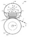
図1は、本発明に係る定着装置の一例が装着された画像形成装置の断面構成図である。この画像形成装置の全体的な構成と動作については後述するとして、先に定着装置について説明する。
【0032】
図2は、定着装置の第1実施例を示す断面構成図である。この図に示す定着装置50Aは、定着ベルト51、加圧ローラ52、ヒータ53,54、定着押圧部材55等から構成されており、これらが図示しない定着ケーシングに収められている。
【0033】
無端状に構成された定着ベルト51のループ内には、定着ヒータとしての輻射熱源(例えばハロゲンヒータ)53、定着押圧部材55及び熱遮蔽板60が配置されている。輻射熱源53は、定着ベルト51を内側から輻射熱により加熱する。定着ベルト51は、回転時においても略円筒形を維持できるように、円筒軸方向(図面に垂直な方向)の両端部に配置された図示しないガイド部材によってガイドされている。なお、そのガイド部材は、別実施例のもの(ベルトガイド部材67)を図7に示してあるので参照されたい。
【0034】
定着押圧部材55は、支持部材であるホルダ56,断熱部材57,耐熱弾性部材58及び保護シート59等から構成されており、回転することなく固定配置されている。この定着押圧部材55は、保護シート59を介して耐熱弾性部材58が定着ベルト51の内側に接するように加圧ローラ52に対向して設置され、図示しない加圧手段により、定着ベルト51を挟んで加圧ローラ52に一定の加圧力で押し当てられている。すなわち、定着押圧部材55の耐熱弾性部材58と加圧ローラ52が定着ベルト51を介して圧接されることにより、定着ニップを形成している。
【0035】
ところで、弾性押圧部材により定着ベルトを加圧ローラに押圧して定着ニップを得る構成のベルト定着装置においては、弾性押圧部材を支持する部材としてホルダは必須な部材である。また、その支持部材であるホルダは、加工の容易さやコストの面から、金属材料が通常用いられる。しかし従来の定着装置において、支持部材(ホルダ)の熱容量が大きく、また金属製の場合は熱伝導性も高く、本来定着ベルトを加熱するための定着ヒータ(輻射熱源)により支持部材(ホルダ)が加熱されることによって、無駄な熱移動が生じ、定着ベルトの加熱効率が低下してしまう。
【0036】
そこで、本実施例においては、輻射熱源53と定着押圧部材55の間に(定着押圧部材55の上に)熱遮蔽板60を設けてある。この熱遮蔽板60により定着押圧部材55(特にホルダ56)への熱移動を防止し、ベルトの加熱効率を向上させるようにしている。また、図示の如く、本例では熱遮蔽板60の両端に断熱キャップ61,61が装着してあり、定着ベルト51と熱遮蔽板60とが直接に接触することを防ぎ、定着ベルト51から熱遮蔽板60への熱移動を防止する効果がある。また、本例では、ホルダ56の図における両端部を上方に突出させて(H字状の両端部上面に)熱遮蔽板60を装着・支持することにより、ホルダ56と熱遮蔽板60の接触面積を最小限に抑えるとともに、両者間に空気層62を形成することにより、断熱効果をさらに高めている。
【0037】
熱遮蔽板60は本実施例ではアルミ板を用いており、表面(少なくとも熱源側)の光沢性によってハロゲンランプの光を反射して断熱効果を高めている。熱遮蔽板60としては、アルミに限らず他の金属材料や耐熱樹脂材料等を用いることが可能である。その場合、表面(少なくとも熱源側)に光反射性を高める処理、例えばアルミ蒸着や金・銀メッキなどを施すと好適である。
【0038】
上記の断熱キャップ61は、熱遮蔽板60の両端部に、円筒状定着ベルトの軸方向(図面に垂直な方向)のほぼ全長にわたる長さを有して装着されており、例えばフェルト,発泡シリコーン,耐熱樹脂部材等を使用することができる。熱遮蔽板60に断熱キャップ61を装着することにより、熱遮蔽板60上方(熱源側)の加熱された空気が熱遮蔽板60の下方に回りこむことを防ぐことができる。なお、図面に垂直な方向の両端部側においても、図7に示す別実施例のベルトガイド部材67と同様の構成により円筒ベルトの両端部が略密閉されているので、熱遮蔽板60上方(熱源側)の加熱された空気が熱遮蔽板60の下方に回りこむことを防ぐことができる。これにより、上記した定着ベルト51と熱遮蔽板60との接触による熱移動防止に加えて、対流による定着押圧部材55(特にホルダ56)への熱移動を防ぎ、ベルトの加熱効率をさらに向上させている。そして断熱キャップ61は、定着ベルト51が回転する際に、ベルト内周面が断熱キャップ61と摺接しながら回転することにより、ベルトの略円筒形状を維持するガイド部材の機能も果たしている。
【0039】
定着ベルト51の外周面に接触または近接して温度検知手段、例えばサーミスタ63が設けてある。この温度検知センサ63で検出したベルト51の温度に基づいて、熱源53への通電が制御される。温度検知センサ63の配置位置としては、熱源53により加熱される定着ベルト51の正確な温度を検出するため、輻射熱源53によって直接に加熱を受けるベルトの範囲、本例ではハロゲンヒータ53の光を直接に受ける領域に、温度検知センサ63を配置している。
【0040】
仮に、温度検知センサ63を熱遮蔽板60の下方のベルト領域に配置した場合、輻射熱源53からの熱は熱遮蔽板60や定着押圧部材55によって遮られることになる。すると、何らかの原因でベルトが正常に回転しなかったときに、検知部領域ではベルト温度があまり上昇せずに熱源への通電が持続され、直接に加熱を受ける部分でベルトが過熱して発火する危険がある。しかし、本例では、上記のように、輻射熱源53によって直接に加熱を受けるベルトの範囲に温度検知センサ63を配置することによって、そのような危険を未然に防止している。
【0041】
加圧ローラ52は、図示しない駆動機構により図中反時計回りに回転駆動される。加圧ローラ52が回転することにより、定着ベルト51は図中時計回りに連れ回りする。定着押圧部材55は、ホルダ56の一方側の側面から耐熱弾性部材58の下面を回ってホルダの他方側の側面までを覆うように設けられた保護シート59によって保護されており、定着ベルト51が回転するとき、ベルトは内周面が保護シート59と摩擦摺動しながら回転する。保護シート59を摺動性に優れた低摩擦の耐熱フィルム材とすることで、ベルト回転時の摺動抵抗を低減させることができる。定着ベルト51と定着押圧部材55(の耐熱弾性部材58)との摺動抵抗を低減させることにより、加圧ローラ52に従動回転される定着ベルト51のスリップを防止することができる。また、耐熱弾性部材58の磨耗を防止する効果もある。
【0042】
保護シート59の材料としては、PI(ポリイミド),ガラス繊維,PIA(ポリイミドアミド),PES(ポリエーテルサルフォン),PEEK(ポリエーテルエーテルケトン)材などを用いることができ、これらにフッ素樹脂を含有させたりコーティングしても良い。保護シート59は、図における左右両端部をホルダ56の側面に固着されており、加圧部材に面する側、図1では下方側にたるみ(図示せず)を有する長さに設定されている。このため、当初は(非加圧時は)保護シート59が耐熱弾性部材58から離間してたるんでいるが、耐熱弾性部材58が加圧部材、ここでは加圧ローラ52に当接されるときには、保護シート59が加圧部材の形状に倣って耐熱弾性部材58に密着し、これを保護するように構成されている。
【0043】
加圧ローラ52は、弾性層52aを有しており、内部にヒータ54、例えばハロゲンヒータを配置している。また、加圧ローラ52の外周に接触または近接して温度検知手段、例えばサーミスタ64が設けてある。サーミスタ64で検出した加圧ローラ温度に基づいて、熱源54への通電が制御される。
【0044】
上記のような構成の定着装置50Aにおいて、未定着トナー像Tを担持する記録紙Pを、定着押圧部材55により定着ベルト51と加圧ローラ52とが圧接される定着ニップに通過させることにより、未定着トナーが熱と圧力とにより記録紙P上に定着される。
【0045】
さて、本実施例においては、定着押圧部材55の耐熱弾性部材58は、図3に示すように、定着ニップを形成する面58a(加圧ローラ52との当接面、保護シートを介して当接する面)が当初から加圧ローラ52の外周面に倣う凹状に形成されている。つまり、非加圧時において耐熱弾性部材58のニップ形成面58aが加圧ローラ52(加圧部材)の形状に倣う(略同一)形状となっている。これにより、従来の四角形状の弾性部材を押圧して加圧部材の形状に倣うように変形させる場合と比べ、低荷重で(低い加圧力で)広いニップ幅を得ることができる。そのため、低温(従来より低い温度での)定着が可能となり定着装置の立ち上がり時間を短くすることができる。また、加圧力を低くできることから小径薄肉な加圧ローラを使用することが可能となり、加圧部材の熱容量を小さくして立ち上げ時間を短縮することが可能となる。もちろん、待機時の予熱を少なくできるので、省エネ効果も優れている。
【0046】
なお、耐熱弾性部材58の定着ニップ形成面58aは、完全に加圧部材の形状と同一でなくとも良い。例えば、加圧ローラ形状に倣いつつ(凹形状を維持しつつ)、ニップ出口側加圧力がニップ入口側より高くなるような形状とすることもできる。これにより、ニップ出口側で充分な加圧力を与え、梨地画像の予防など画質の向上をはかることも可能である。
【0047】
従来の四角形状の弾性部材を加圧ローラに押圧して変形させる場合、必然的に中央部での加圧力が高くなるが、耐熱弾性部材58の定着ニップ形成面を非加圧時において加圧部材の形状に近い形状に構成する場合、必要な定着性能が得られるようにニップ形成面の形状を設計することにより、記録紙のニップへの導入性向上、低荷重で充分なニップ幅を得ることによる定着性向上及び立上げ時間短縮、ニップ出口側で加圧力を大きくして梨地画像の予防など、所望の定着性能を同時に得ることが容易に実現できる。
【0048】
また、耐熱弾性部材58のニップ入口側の角部にR(丸み)を設けてもよい。これにより、記録紙の定着ニップへの導入をスムーズにするとともに、耐熱弾性部材58端部の巻き込み(ニップ内への)を防止する効果もある。また、耐熱弾性部材58のニップ出口側の角部にR(丸み)を設けて、定着ベルト51が急角度で屈曲することによる劣化を防ぐこともできる。ニップ入口側と出口側の双方の角部にR(丸み)を設ける場合は、出口側Rの曲率を入口側より小さくすると好適である。これにより、定着された記録紙の分離性低下(Rを設けたことによる分離性低下)を最小限にとどめることができる。
【0049】
次に、定着装置の第2実施例を図4により説明する。この実施例の定着装置50Bは、基本的構成は図2の定着装置50Aと同様であるので、重複する説明を省略し、異なる部分について説明する。
【0050】
図4に示すように、本例の定着装置50Bでは、定着押圧部材55のホルダ56Bの上に断熱部材65を固定し、この断熱部材65に熱遮蔽板60を装着して支持している。これ以外の構成は図2の定着装置50Aと同様である。
【0051】
断熱部材65としては、シリコーン,耐熱樹脂発泡体,耐熱樹脂等を用いることができる。本実施例では、熱遮蔽板60を断熱部材65を介して支持することにより、断熱効果を高めて熱損失をより小さくし、輻射熱源53による定着ベルト51の加熱効率を向上させている。
【0052】
次に、定着装置の第3実施例を図5により説明する。この実施例の定着装置50Cは、基本的構成は図2の定着装置50Aと同様であるので、重複する説明を省略し、異なる部分について説明する。
【0053】
図5に示すように、本例の定着装置50Cでは、定着押圧部材55のホルダ56Cの上に小さな2つの断熱部材66,66を設け、この断熱部材66,66に熱遮蔽板60を装着して支持している。これ以外の構成は図2の定着装置50Aと同様である。
【0054】
断熱部材66としては、シリコーン,耐熱樹脂発泡体,耐熱樹脂等を用いることができる。本実施例では、断熱部材66,66の間、すなわちホルダ56Cと熱遮蔽板60の間に空気層62を形成することにより、断熱効果を高めている。
【0055】
次に、定着装置の第4実施例を図6,7により説明する。この実施例の定着装置50Dは、基本的構成は図2の定着装置50Aと同様であるので、重複する説明を省略し、異なる部分について説明する。
【0056】
図6,7に示すように、本例の定着装置50Dでは、熱遮蔽板60は、円筒形ベルトループの軸方向端部において、定着側板69に固定されたベルトガイド部材67にはめ込まれて固定・支持されている。これ以外の構成は図2の定着装置50Aと同様である。
【0057】
本実施例においては、熱遮蔽板60をベルトガイド部材67により支持しているため、定着押圧部材55のホルダ56Dと熱遮蔽板60は離間しており、両者の間に空気層62が形成されている。これにより、断熱効果を高め輻射熱源53による定着ベルト51の加熱効率を向上させている。
【0058】
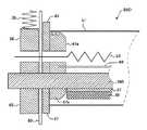
ループ状の定着ベルト51は、両端部をベルトガイド部材67の凸部67aによりガイドされることで、略円筒形を維持するように構成されている。そして、定着押圧部材55のホルダ56Dを定着側板69の外側で支持する支持部材68にスプリング70の加圧力が付与され、加圧ローラ52に対して耐熱弾性部材58を介して定着ベルト51が圧接される。この、ベルト支持及び加圧ローラ52へのベルト圧接の構成は、他の実施例の定着装置においても同様である。
【0059】
次に、定着装置の第5実施例を図8により説明する。この実施例の定着装置50Eは、基本的構成は図2の定着装置50Aと同様であるので、重複する説明を省略し、異なる部分について説明する。
【0060】
図8に示すように、本例の定着装置50Eでは、定着押圧部材55のホルダ56Eの上に断熱部材71を装着し、その断熱部材71の上面(熱源側)に熱遮蔽膜72を設けている。これ以外の構成は図2の定着装置50Aと同様である。
【0061】
断熱部材71としては、シリコーン,耐熱樹脂発泡体,耐熱樹脂等を用いることができる。熱遮蔽膜72は、低熱容量の薄い材料、例えばアルミ,鉄,銅,SUS等の金属箔またはシートを用い、表面に光反射率を高める処理(アルミ蒸着等)を施してある。本実施例では、熱遮蔽膜72を断熱部材71の表面に設けることにより、断熱効果を高めて熱損失をより小さくし、輻射熱源53による定着ベルト51の加熱効率を向上させている。
【0062】
次に、定着装置の第6実施例を図9により説明する。この実施例の定着装置50Fは、基本的構成は図2の定着装置50Aと同様であるので、重複する説明を省略し、異なる部分について説明する。
【0063】
図9に示すように、本例の定着装置50Fでは、定着押圧部材55のホルダ56Fの外側に小さな断熱部材74を介して熱遮蔽膜73を装着・支持している。これ以外の構成は図2の定着装置50Aと同様である。
【0064】
熱遮蔽膜73は、低熱容量の薄い材料、例えばアルミ,鉄,銅,SUS等の金属箔またはシートを用い、断熱部材74としては、シリコーン,耐熱樹脂発泡体,耐熱樹脂等を用いることができる。本実施例では、断熱部材74,74の間、すなわちホルダ56Fと熱遮蔽膜73の間に空気層62を形成することにより、断熱効果を高めている。
【0065】
次に、定着装置の第7実施例を図10により説明する。この実施例の定着装置50Gは、基本的構成は図2の定着装置50Aと同様であるので、重複する説明を省略し、異なる部分について説明する。
【0066】
図10に示すように、本例の定着装置50Gでは、定着押圧部材55のホルダ56Gの上に熱遮蔽板60を装着・支持し、その熱遮蔽板60に断熱部材75,75を介して熱遮蔽膜72を設けている。熱遮蔽膜72は図8のものと同じである。また、断熱部材75は、図2の実施例における断熱キャップ61に相当し、同様の機能を果たす。本実施例では、熱遮蔽膜72と熱遮蔽板60とが2重に設けられており、かつ両者間に空気層62を形成することにより、断熱効果をさらに高めている。
【0067】
ここで、定着ベルト51を加圧ローラ52に押圧して定着ニップを得るための耐熱弾性部材58の変形例を2例説明する。
まず、図11に示す耐熱弾性部材58−2は、部材が当初から(非加圧時において)加圧部材、ここでは加圧ローラ52の形状に倣うような、略円弧形状に形成されているものである。本例の耐熱弾性部材58−2は、図に示すような形状に工場にて加工・製造されたものである。その耐熱弾性部材58−2を、装着面が同様な形状をしているホルダ56または断熱部材57に装着する。本例の耐熱弾性部材58−2は、工場にて所定形状に加工・製造されたものであるため、所望する加圧性能すなわち定着性能を確実に得ることができる。
【0068】
図12に示す耐熱弾性部材58−3は、当初(非加圧時)の形状は図に示すような矩形断面の直方体として形成されている。その耐熱弾性部材58−3を、装着面が加圧部材、ここでは加圧ローラ52の形状に倣うように凹んだ形状をしているホルダ56(または断熱部材57)に装着する。これによって、耐熱弾性部材58−3が変形して、そのニップ形成面が加圧ローラ52に倣う形状となる。本例の耐熱弾性部材58−3は、単純な直方体として形成された耐熱弾性部材を使用しているので、均一な加圧力を低コストに得ることができる。
【0069】
なお、耐熱弾性部材58(58−2,58−3)を直接ホルダ56に装着する場合、ホルダ56は、定着押圧部材55のホルダ(支持部材)であると同時に、耐熱弾性部材が装着される被装着部材である。耐熱弾性部材58(58−2,58−3)を断熱部材57を介してホルダ56に装着する場合は、断熱部材57が被装着部材、ホルダ56は支持部材である。
【0070】
ここで説明した図11及び図12の2つの変形例の耐熱弾性部材は、前記各実施例の定着装置50A〜50Gの定着押圧部材55における耐熱弾性部材として使用することができる。
【0071】
次に、定着装置の第8実施例を図13により説明する。
この図に示す定着装置50Hは、定着ベルト51,加圧ローラ52,駆動ローラ76,加熱ローラ77,定着押圧部材55及びベルトガイド78等からなり、これらが図示しない定着ケーシングに収められている。
【0072】
定着ベルト51のループ内には駆動ローラ76、加熱ローラ77、ホルダ56Hと耐熱弾性部材58とからなる定着押圧部材55及びベルトガイド78を内包している。加熱ローラ77内には定着ヒータとしてのハロゲンヒータ53が内蔵されている。また、加圧ローラ52にはハロゲンヒータ54が内蔵されている。定着ベルト51は、ハロゲンヒータ53により加熱ローラ77を介して加熱される。
【0073】
本実施例の定着装置において、定着ベルト51を加圧ローラ52に押圧して定着ニップを形成させるための定着押圧部材55の耐熱弾性部材58は、そのニップ形成面、すなわち加圧ローラ52に対向する面が、当初から(非加圧時に)加圧部材、ここでは加圧ローラ52の外周面に倣う形状に形成されている。これにより、低荷重で(低い加圧力で)所望のニップ幅を得ることができる。したがって、小径薄肉な加圧ローラを使用することが可能となり、加圧部材の熱容量を小さくして定着装置の立ち上がり時間を短くすることが可能となる。
【0074】
ここまで、輻射熱により定着ベルト51を直接加熱する第1〜第7実施例、および、加熱部材(加熱ローラ77)を介して熱伝導により定着ベルト51を加熱する第8実施例により、定着押圧部材55の耐熱弾性部材58が当初から(非加圧時に)加圧部材に倣う形状に形成されていることについて説明したが、本発明による、当初から(非加圧時に)加圧部材に倣う形状に形成されている耐熱弾性部材(定着ベルトを押圧してニップを形成させるための弾性部材)は、他の加熱方式、例えば誘導加熱により定着ベルトを加熱する構成の定着装置においても適用できるものであり、その場合でも、低荷重で(低い加圧力で)所望のニップ幅を得ることができる。したがって、小径薄肉な加圧ローラを使用することが可能となり、加圧部材の熱容量を小さくして定着装置の立ち上がり時間を短くすることが可能となる。また、耐熱弾性部材を所望の定着性能を発揮するような設計とすることにより、画質向上など必要な定着性能を同時に得ることが容易に実現できる。また、ベルトループ外から定着ベルトを加熱する方式においても、定着ベルトを加圧部材に加圧するための弾性部材を、上記説明した耐熱弾性部材58のように、当初から(非加圧時に)加圧部材に倣う形状とすることができる。ベルトループ外から定着ベルトを加熱する場合、加熱方式はハロゲンヒータ等のヒータに限らず、誘導加熱でも良く、直接加熱または間接加熱のどちらでも可能である。あるいは、定着ベルト内部に(ベルトの層内に)抵抗発熱層を設ける方式にも適用可能である。
【0075】
図14は、上記各実施例の定着装置に使用可能な加圧ローラの一例における、ローラ芯金の構成例を示す断面構成図である。
この図に示すように、加圧ローラ52の芯金は、その内周面側に複数の補強用リブ52bが設けられている。この補強用リブ52bは円筒形芯金の内面に周方向に突設されているものであり、リブの断面形状としては図に(a)〜(c)で示すような形状とすることができる。すなわち、(a)に示すものは、略半円形の断面形状を有する補強用リブであり、(b)に示すものは、角が丸められた矩形断面形状を有する補強用リブであり、(c)に示すものは、略三角形(あるいは台形)断面形状を有する補強用リブである。
【0076】
これらの補強用リブの加工方法の一例を説明する。先ず、加圧ローラの素材となる金属(例えばアルミ)素管の外周面に所定の工具を押接して素管を回転させ(あるいは工具を回転させ)、金属素管の外周面を凹陥させて素管内周側に周回凸部を突出形成させる。この素管内周側に形成された周回凸部が補強用リブである。そして、周回凸部すなわち補強用リブを形成した後に、金属素管の軸方向に切削工具を移動させながら金属素管の外周面を均一に(平に)切削して、所定肉厚(非リブ部)のローラ芯金に仕上げる。
【0077】
最後に、図1のプリンタの概略構成と動作について簡単に説明する。なお、定着装置としては上記説明した各実施例のものを装着可能であり、図1では定着装置の符号を50としてある。
【0078】
図1に示すカラーレーザプリンタ1では、装置本体の下部に給紙部2が設けられ、その上方に作像部3を配置した構成となっている。装置上面には排紙トレイ40が形成されている。図に破線で記録紙の搬送経路を示すように、給紙部2から用紙を給送し、作像部3にて形成した画像を用紙上に転写し、定着装置50で定着して排紙トレイ40に排紙する。なお、装置側面からは手差し給紙(符号:h)が可能である。
【0079】
また、装置本体の側面には両面装置90が装着されており、定着後に用紙を表裏反転させ、両面搬送部30を経て再給紙することも可能である。また、両面装置90から、装置側面方向の図示しない排紙トレイに用紙を排出することが可能である。
【0080】
作像部3には、給紙側を下に、排紙側を上となるように傾斜して配置された転写搬送ベルト装置20が配設されている。この転写搬送ベルト装置20の上部走行辺に沿って、下から順にマゼンタ(M)、シアン(C)、イエロー(Y)、黒(Bk)用の4つの作像ユニット4M,4C,4Y,4Bkが並んで配置されている。
【0081】
各作像ユニット4M,4C,4Y,4Bkの構成は同じであるので、ここでは各色を示すアルファベット(M,C,Y,Bk)を省いて説明する。
各作像ユニット4は、像担持体としての感光体ドラム5を備えており、該感光体ドラム5は図示していない駆動手段によって図中時計方向へ回転駆動される。感光体ドラム5の回りには帯電ロール,現像装置,クリーニング装置等が設けられている。現像装置は本例ではトナーとキャリアからなる2成分現像装置であって、現像ロールに担持したトナーを感光体ドラム5に付与する。光書込み装置8からのレーザ光は、帯電ロールと現像ロールの間から感光体ドラム5に照射される。
【0082】
無端ループ状の転写搬送ベルト21は、駆動ローラ22、従動ローラ23及び2つの対向ローラ24,24に巻回張架されている。転写搬送ベルト21の上部走行辺の内側で、各色作像ユニット4M,4C,4Y,4Bkの感光体ドラム5に夫々対向する位置に、転写ブラシ28がベルト21に接触するように配置されている。この転写ブラシ28には転写バイアスが印加される。そして、従動ローラ23の上部にはベルト21を挟んで紙吸着ローラ27が設けられている。記録紙は従動ローラ23と吸着ローラ27の間からベルト21上に送り出され、吸着ローラ27に印加されたバイアス電圧によって静電的に転写搬送ベルト21上に吸着された状態で搬送される。
【0083】
転写搬送ベルト装置20は、図示しない機構により、カラープリントの場合はベルト21が4色の作像ユニット4M,4C,4Y,4Bk(の感光体ドラム)に接触する状態に保持され、黒単色プリントの場合は作像ユニット4Bk(の感光体ドラム)のみにベルト21が接触する状態を保持するようになっている。
【0084】
次に、プリント動作について説明する。
マゼンタ用の作像ユニット4Mにおいて、感光体ドラム5の表面は帯電ロール6によって所定の電位に均一に帯電される。露光装置8においては、パソコン等のホストマシーンより送られた画像データに基づいて図示しないLD(レーザダイオード)を駆動してレーザ光をポリゴンミラー7に照射し、シリンダーレンズ等を介して反射光を感光体ドラム5M上に導き、感光体ドラム5M上にマゼンタトナーで現像すべき静電潜像を形成する。この潜像に現像装置10からトナーが付与され、マゼンタトナーの可視像となる。
【0085】
一方、給紙部2からは転写材として指定された用紙が給紙され、給紙された用紙は転写搬送ベルト装置20の搬送方向上流側に設けられたレジストローラ対40に一旦突き当てられる。カラープリント時、転写搬送ベルト装置20では、上述したように転写搬送ベルト21が押し上げられ、ベルト21が4色の作像ユニット4M,4C,4Y,4Bk(の感光体ドラム)に接触している。そして、用紙は上記可視像に同期するようにしてベルト21上に給送され、該ベルトの走行により感光体ドラム5Mに対向する転写位置に到る。この転写位置では、転写ベルト20の裏面側に配置された転写ブラシ28の作用によりマゼンタトナーの可視像が用紙に転写される。
【0086】
マゼンタ色の場合と同様にして、他の作像ユニット4C,4Y,4Bkにおいてもそれぞれの感光体ドラム5の表面に各トナーによる可視像が形成され、これら可視像は転写搬送ベルト21によって搬送される用紙が各転写位置に到来するごとに重ね転写される。したがって、本実施形態のカラープリンタはフルカラーの画像がモノクロとほぼ同様な短時間で用紙に重ね転写される。
【0087】
いっぽう、モノクロプリントの場合は、転写搬送ベルト装置20では、上述したように転写搬送ベルト21が下降され、作像ユニット4Bk(の感光体ドラム)のみにベルト21が接触している。そして、黒用の作像ユニット4Bkのみにおいて感光体ドラム5の表面にブラックトナーの可視像が形成され、このBkの可視像に同期するようにしてベルト21上に給送された用紙に対してBkトナー像が転写される。
【0088】
トナー像転写後の用紙は、転写搬送ベルト21から分離されて、定着装置50により定着される。定着を終えた用紙は、装置本体の上面に設けられた排紙トレイ40に排紙されるか、両面装置90へ受け渡される。
【0089】
両面装置90から装置側面方向の図示しない排紙トレイに用紙を排出することもできるし、両面記録の場合は両面装置90にて用紙の表裏を反転させ、両面搬送部30を経て作像部3に用紙を再給紙し、用紙裏面に画像形成装置を形成することができる。両面記録後の用紙は、装置上面の排紙トレイ40又は装置側面方向の図示しない排紙トレイに排出される。
【0090】
以上、本発明を図示例により説明したが、本発明はこれに限定されるものではなく、適宜な変更が可能である。例えば、定着ベルトの加熱方式は任意なものを採用することができる。また、弾性押圧部材を支持するホルダは金属に限らず、樹脂やセラミックなど適宜な材料を用いることができる。さらに、加圧部材としては加圧ローラ以外のものを採用することも可能であり、その場合でも、弾性押圧部材のニップ形成面を、非圧接時において加圧部材のニップ形成部の形状と略同一な形状に形成すれば良い。もちろん、画像形成装置各部の構成も任意であり、画像形成装置としては、プリンタに限らず、複写機やファクシミリあるいは複合機であっても構わない。
【0091】
【発明の効果】
以上説明したように、本発明の定着装置及び画像形成装置によれば、定着ベルトのループ内に配置され定着ベルトを加圧部材に圧接させる弾性押圧部材のニップ形成面が、非圧接時において加圧手段のニップ形成部の形状と略同一な形状を有しているので、低い加圧力で広いニップ幅を得ることができる。
【0092】
請求項2の構成により、弾性押圧部材は、そのニップ形成面が非圧接時において加圧手段のニップ形成部の形状と略同一な形状であるように加工・製造されているので、所望する加圧性能すなわち定着性能を確実に得ることができる。
【0093】
請求項3の構成により、弾性押圧部材を被装着部材に装着することにより、弾性押圧部材が変形してそのニップ形成面が加圧手段のニップ形成部の形状と略同一な形状となるので、加圧手段とニップ形成部の形状と略同一な形状であるようにニップ形成面が加工・製造された弾性押圧部材に限らず、均一な加圧力を低コストに得ることができる。
【0094】
請求項4の構成により、弾性押圧部材のニップ入口側の端部が丸みを帯びた形状に形成されているので、記録紙の定着ニップへの導入をスムーズにするとともに、弾性押圧部材端部の巻き込み(ニップ内への)を防止することができる。
【0095】
請求項5の構成により、弾性押圧部材のニップ入口側の端部および出口側の端部が丸みを帯びた形状に形成されており、ニップ出口側端部の曲率がニップ入口側端部の曲率よりも小さいので、記録紙の定着ニップへの導入をスムーズにするとともに、弾性押圧部材端部の巻き込み(ニップ内への)を防止することができる。また、定着ベルトが急角度で屈曲することによる劣化を防ぐことができる。定着された記録紙の分離性低下を最小限にとどめることもできる。
【0096】
請求項6の構成により、弾性押圧部材は低摩擦部材からなる保護シートを介して定着ベルト内面に接触するので、ベルト回転時の摺動抵抗を低減させることができる。また、定着ベルトのスリップを防止することができる。弾性押圧部材の磨耗を防止する効果もある。
【0097】
請求項7の構成により、保護シートは、非圧接時は弾性押圧部材のニップ形成面から離間しており、圧接時に弾性押圧部材のニップ形成面に密着されるので、圧接時に保護シートが引っ張られることなくニップ形成面に沿って介在することができる。
【0098】
請求項8の構成により、加熱手段が定着ベルトのループ内に配置された輻射熱源であり、その輻射熱源と弾性押圧部材を支持する支持部材との間に熱遮蔽部材を設けたので、弾性押圧部材及び支持部材への熱移動を防止し、定着ベルトの加熱効率を向上させることができる。
【0099】
請求項9の構成により、熱遮蔽部材の定着ベルト内面と対向する両端部が、断熱部材により被覆されているので、定着ベルトと熱遮蔽部材とが直接に接触することを防ぎ、定着ベルトから熱遮蔽部材への熱移動を防止することができる。
【0100】
請求項10の構成により、断熱部材により両端部を被覆された熱遮蔽部材によって定着ベルトのループ内空間が加熱手段側空間と弾性押圧部材側空間とに仕切られ、加熱手段によって加熱された空気の弾性押圧部材側空間への対流を防止するよう構成されているので、対流による熱移動を防いで定着ベルトの加熱効率を向上させることができる。
【0101】
請求項11の構成により、定着ベルトは略円筒形ループの軸方向の両端側でベルトガイド部材によりガイドされて略密閉されているので、加熱された空気の軸方向からの対流を防ぎ、定着ベルトの加熱効率をより向上させることができる。
【0102】
請求項12の構成により、熱遮蔽部材と支持部材との間に空気層が形成されているので、支持部材への熱移動を防いで断熱効果を高めることができる。
請求項13の構成により、熱遮蔽部材が断熱部材を介して支持部材に装着・支持されているので、支持部材への熱移動を防いで断熱効果を高めることができる。
【0103】
請求項14の構成により、熱遮蔽部材が断熱部材を介して支持部材に装着・支持されているとともに、熱遮蔽部材と支持部材との間に空気層が形成されているので、支持部材への熱移動を効果的に防いでさらに断熱効果を高めることができる。
【0104】
請求項15の構成により、熱遮蔽部材が定着ベルトをガイドするガイド部材に装着・支持されており、その熱遮蔽部材と支持部材とが離間しているので、両者間に空気層が形成されることになり、支持部材への熱移動を防いで断熱効果を高めることができる。
【0105】
請求項16の構成により、熱遮蔽部材が、支持部材に装着された断熱部材と、その断熱部材の熱源側に装着された熱遮蔽膜とからなるので、支持部材への熱移動を効果的に防いで断熱効果をより高めることができる。
【0106】
請求項17の構成により、支持部材と熱遮蔽膜との間に空気層が形成されているので、さらに断熱効果を高めることができる。
請求項18の構成により、熱遮蔽部材が、熱遮蔽板とその熱遮蔽板上に断熱部材を介して装着された熱遮蔽膜とからなり、熱遮蔽板と熱遮蔽膜との間に空気層が形成されているので、2重となった熱遮蔽板と熱遮蔽膜と、その間の空気層とによって、熱移動を効果的に防いで断熱効果をさらに高めることができる。
【0107】
請求項19の構成により、熱遮蔽部材または熱遮蔽膜は、少なくとも前記熱源側の面が輻射熱に対する反射性を有しているので、断熱効果を高めることができる。
【0108】
請求項20の構成により、定着ベルトの温度を検知する温度検知手段を、輻射熱源により定着ベルトが直接加熱される領域のベルト外面に接触または近接して配置したので、常に正確なベルト温度を検出することができ、過熱による出火等の危険を防ぐことができる。
【0109】
請求項21の定着装置によれば、定着ベルトのループ内に配置された加熱手段と弾性押圧部材を支持する支持部材との間に熱遮蔽部材を設け、加熱手段から弾性押圧部材及び支持部材への熱移動を防止するよう構成されているので、定着ベルトの加熱効率を向上させることができる。
【図面の簡単な説明】
【図1】本発明に係る定着装置の一例が装着された画像形成装置の断面構成図である。
【図2】定着装置の第1実施例を示す断面構成図である。
【図3】定着ベルトを加圧ローラに押圧して定着ニップを形成するための耐熱弾性部材を示す側面図である。
【図4】定着装置の第2実施例を示す断面構成図である。
【図5】定着装置の第3実施例を示す断面構成図である。
【図6】定着装置の第4実施例を示す断面構成図である。
【図7】定着ベルトの軸方向の端部付近を示す断面図である。
【図8】定着装置の第5実施例を示す断面構成図である。
【図9】定着装置の第6実施例を示す断面構成図である。
【図10】定着装置の第7実施例を示す断面構成図である。
【図11】耐熱弾性部材の別例を示す模式図である。
【図12】耐熱弾性部材のさらに別の例を示す模式図である。
【図13】定着装置の第8実施例を示す断面構成図である。
【図14】各実施例の定着装置に使用可能な加圧ローラの一例における、ローラ芯金と補強リブを示す断面図である。
【符号の説明】
1 カラーレーザプリンタ
50 定着装置
51 定着ベルト
52 加圧ローラ(加圧部材)
53 ヒータ(加熱手段、輻射熱源)
55 定着押圧部材
56 ホルダ(支持部材、被装着部材)
57 断熱部材(被装着部材)
58 耐熱弾性部材(押圧弾性部材)
59 保護シート
60 熱遮蔽板
61 断熱キャップ
65,66 断熱部材
67 ベルトガイド部材
71,74,75 断熱部材
72,73 熱遮蔽膜
76 駆動ローラ
77 加熱ローラ[0001]
TECHNICAL FIELD OF THE INVENTION
The present invention relates to a heat fixing device in an image forming apparatus such as a copying machine, a printer, and a facsimile, and more particularly, to a belt fixing device.
[0002]
[Prior art]
2. Description of the Related Art A heat fixing device is widely used in an image forming apparatus such as a copier, a printer, a facsimile, or a multifunction peripheral having a plurality of functions of the copier, the printer, and the facsimile.
[0003]
[0004]
Further, in
[0005]
[Problems to be solved by the invention]
However, in the device described in
[0006]
In the case of
[0007]
SUMMARY OF THE INVENTION It is an object of the present invention to provide a fixing device and an image forming apparatus which can solve the above-described problems in the conventional belt fixing device and the conventional image forming apparatus and can achieve high image quality and energy saving.
[0008]
[Means for Solving the Problems]
According to the present invention, there is provided an endless loop-shaped fixing belt heated by a heating unit, a pressing member to which the fixing belt is pressed, and a fixing member disposed in a loop of the fixing belt and pressing the fixing belt. An elastic pressing member for pressing the recording medium carrying an unfixed toner image through a nip formed by pressing the fixing belt and the pressing member. This is solved by the nip forming surface of the pressing member having substantially the same shape as the nip forming portion of the pressing means when not pressed.
[0009]
Further, in order to solve the above-mentioned problem, the present invention provides a method for processing the elastic pressing member such that a nip forming surface of the elastic pressing member has substantially the same shape as a nip forming portion of the pressing means when not pressed. Propose that it is manufactured.
[0010]
Further, in order to solve the above-mentioned problem, the present invention provides a member to which the elastic pressing member is mounted, wherein an elastic pressing member mounting portion is formed to have substantially the same shape as a nip forming portion of the pressing means. By attaching the elastic pressing member to the mounting portion of the mounted member, the elastic pressing member is deformed and its nip forming surface has a shape substantially the same as the shape of the nip forming portion of the pressing means. Propose to be.
[0011]
Further, in order to solve the above-mentioned problem, the present invention proposes that an end of the elastic pressing member on the nip entrance side is formed in a rounded shape.
Further, in order to solve the above-mentioned problem, the present invention provides an elastic pressing member in which an end on the nip entrance side and an end on the exit side are formed in a rounded shape, and the nip exit side end is It is proposed that the curvature is smaller than the curvature at the nip inlet end.
[0012]
Further, in order to solve the above-mentioned problem, the present invention proposes that the elastic pressing member comes into contact with the inner surface of the fixing belt via a protective sheet made of a low friction member.
Further, in order to solve the above-mentioned problem, the present invention provides the protection sheet, wherein the protective sheet is separated from the nip forming surface of the elastic pressing member during non-pressing, and is in close contact with the nip forming surface of the elastic pressing member during pressing. Propose that.
[0013]
Further, in order to solve the above-described problem, the present invention provides a heating device, wherein the heating unit is a radiant heat source disposed in a loop of the fixing belt, and the heating unit is provided between the radiant heat source and a support member that supports the elastic pressing member. It is proposed to provide a heat shielding member.
[0014]
Further, in order to solve the above problem, the present invention proposes that both ends of the heat shielding member facing the inner surface of the fixing belt are covered with a heat insulating member.
Further, in order to solve the above-described problem, the present invention provides a heat shielding member whose both ends are covered by the heat insulating member, wherein the space in the loop of the fixing belt is the space between the heating unit side space and the elastic pressing member side space. It is proposed to be configured so as to prevent convection of the air heated by the heating means into the space on the elastic pressing member side.
[0015]
Further, in order to solve the above-described problem, the present invention proposes that the fixing belt is guided by a belt guide member at both ends in the axial direction of the substantially cylindrical loop and is substantially sealed.
[0016]
Further, in order to solve the above-mentioned problem, the present invention proposes that an air layer is formed between the heat shielding member and the support member.
In order to solve the above-mentioned problem, the present invention proposes that the heat shielding member is mounted and supported on the supporting member via a heat insulating member.
[0017]
Further, in order to solve the above-described problem, the present invention provides a method in which the heat shielding member is attached to and supported by the support member via a heat insulating member, and an air layer is provided between the heat shielding member and the support member. Is formed.
[0018]
In order to solve the above-described problems, the present invention provides the heat shielding member, which is mounted and supported on a guide member that guides the fixing belt, and the heat shielding member is separated from the support member. Propose that.
[0019]
In order to solve the above problems, the present invention provides that the heat shielding member includes a heat insulating member mounted on the support member and a heat shielding film mounted on the heat source side of the heat insulating member. suggest.
[0020]
Further, in order to solve the above-mentioned problem, the present invention proposes that an air layer is formed between the support member and the heat shielding film.
Further, in order to solve the above problems, the present invention provides the heat shielding member, comprising a heat shielding plate and a heat shielding film mounted on the heat shielding plate via a heat insulating member, wherein the heat shielding plate It is proposed that an air layer is formed between the heat shield film and the heat shield film.
[0021]
Further, in order to solve the above problem, the present invention proposes that the heat shielding member or the heat shielding film has at least a surface on the heat source side having reflectivity to radiant heat.
[0022]
Further, in order to solve the above-mentioned problem, the present invention is arranged such that the temperature detecting means for detecting the temperature of the fixing belt is in contact with or close to the belt outer surface in an area where the fixing belt is directly heated by the radiant heat source. Propose that.
[0023]
Further, according to the present invention, there is provided an endless loop-shaped fixing belt, a heating unit arranged in a loop of the fixing belt and heating the fixing belt by radiant heat, and a pressing member to which the fixing belt is pressed. And an elastic pressing member disposed in a loop of the fixing belt to press the fixing belt against a pressing member, and an unfixed toner image is formed in a nip formed by pressing the fixing belt and the pressing member. In a fixing device that performs fixing by passing a recording material to be carried, a heat shielding member is provided between the heating unit and a support member that supports the elastic pressing member, and a heat shielding member is provided from the heating unit to the elastic pressing member and the supporting member. This is solved by being configured to prevent heat transfer.
[0024]
According to the present invention, the above object is achieved by an image forming apparatus including the fixing device according to any one of
[0025]
BEST MODE FOR CARRYING OUT THE INVENTION
Due to recent environmental regulations and an increase in environmental protection consciousness, in various image forming apparatuses, power supply to the fixing heater is cut off during standby and power is supplied only when necessary, thereby reducing power consumption. In such an energy saving type image forming apparatus, the surface temperature of the fixing member needs to quickly reach the set temperature during printing. In the conventional heat roller method in which the fixing roller is heated by a halogen heater, the thickness of the fixing roller base is reduced to a thickness of 1 mm or less, thereby reducing the heat capacity of the fixing roller and rapidly fixing the fixing roller. To the set temperature.
[0026]
However, when the fixing roller is formed of a rigid body, the contact surface at the time of fixing does not follow irregularities on the recording medium. Even if the level is not a problem for a monochrome machine, it is particularly noticeable for a color machine. Therefore, it is essential at present to provide a fixing surface with elasticity for improving the image quality of a color machine.
[0027]
Therefore, in a color machine, a fixing device in which both a fixing roller and a pressure roller have an elastic layer (mainly silicone rubber) and heats the inside from inside by a halogen heater disposed inside the roller is mainly used. However, in such a roller fixing method, the heat capacity becomes enormous, heat transfer from the inside of the roller to the surface layer is poor, the start-up becomes extremely slow, and it is necessary to always perform residual heat during standby, thereby saving energy. Not be.
[0028]
As a countermeasure, a belt fixing device which is not a fixing roller system in a color machine has been proposed in recent years. The fixing belt is pressed from the inside of the belt loop to the pressing member (pressure roller) by an elastic pressing member and pressed against the pressing member, so that the image quality is improved by a non-rigid fixing member (fixing belt) and the fixing member (fixing belt) having a small heat capacity ) Shortens the start-up time.
[0029]
On the other hand, in a belt fixing device in which a fixing belt is pressed by an elastic pressing member and is brought into contact with a pressure roller to form a fixing nip, the pressure roller is thinned to prevent deformation of the pressure roller due to fixing pressure. However, it is difficult to further reduce the startup time and save energy.
[0030]
In the configuration having the elastic pressing member, a member (holder) for supporting the elastic pressing member is indispensable at present, and the heat capacity of the supporting member (holder) is large. Therefore, the heating efficiency of the fixing belt decreases due to the heat transfer from the heat source, and it is difficult to further reduce the start-up time and save energy.
[0031]
A specific configuration of the present invention for realizing further reduction in the startup time and energy saving in the belt fixing device will be described below with reference to the drawings.
FIG. 1 is a cross-sectional configuration diagram of an image forming apparatus to which an example of a fixing device according to the present invention is attached. The overall configuration and operation of the image forming apparatus will be described later, and the fixing device will be described first.
[0032]
FIG. 2 is a sectional view showing a first embodiment of the fixing device. The fixing device 50A shown in FIG. 1 includes a fixing
[0033]
A radiant heat source (for example, a halogen heater) 53 as a fixing heater, a
[0034]
The
[0035]
By the way, in a belt fixing device configured to obtain a fixing nip by pressing a fixing belt against a pressure roller with an elastic pressing member, a holder is an essential member as a member for supporting the elastic pressing member. Further, a metal material is usually used for the holder as the support member from the viewpoint of easiness of processing and cost. However, in the conventional fixing device, the heat capacity of the supporting member (holder) is large, and the thermal conductivity is high in the case of metal, and the supporting member (holder) is originally formed by a fixing heater (radiant heat source) for heating the fixing belt. Heating causes wasteful heat transfer, which lowers the heating efficiency of the fixing belt.
[0036]
Therefore, in this embodiment, a
[0037]
In this embodiment, the
[0038]
The heat-insulating
[0039]
A temperature detecting unit, for example, a
[0040]
If the
[0041]
The
[0042]
As a material of the
[0043]
The
[0044]
In the fixing device 50A having the above-described configuration, the recording paper P carrying the unfixed toner image T is passed by the
[0045]
In this embodiment, as shown in FIG. 3, the heat-resistant
[0046]
Note that the fixing nip forming
[0047]
When the conventional rectangular elastic member is pressed against the pressure roller to be deformed, the pressing force inevitably increases at the center, but the fixing nip forming surface of the heat-resistant
[0048]
Further, R (roundness) may be provided at a corner of the heat-resistant
[0049]
Next, a second embodiment of the fixing device will be described with reference to FIG. The fixing device 50B of this embodiment has a basic configuration similar to that of the fixing device 50A of FIG. 2, and thus a duplicate description will be omitted, and different portions will be described.
[0050]
As shown in FIG. 4, in the fixing
[0051]
As the
[0052]
Next, a third embodiment of the fixing device will be described with reference to FIG. The fixing device 50C of this embodiment has a basic configuration similar to that of the fixing device 50A of FIG. 2, and thus a duplicate description will be omitted, and only different portions will be described.
[0053]
As shown in FIG. 5, in the fixing device 50C of this embodiment, two small
[0054]
As the
[0055]
Next, a fourth embodiment of the fixing device will be described with reference to FIGS. The fixing
[0056]
As shown in FIGS. 6 and 7, in the fixing
[0057]
In the present embodiment, since the
[0058]
The loop-
[0059]
Next, a fifth embodiment of the fixing device will be described with reference to FIG. The fixing
[0060]
As shown in FIG. 8, in the
[0061]
As the
[0062]
Next, a sixth embodiment of the fixing device will be described with reference to FIG. The fixing device 50F of this embodiment has a basic configuration similar to that of the fixing device 50A of FIG. 2, and thus a duplicate description will be omitted, and different portions will be described.
[0063]
As shown in FIG. 9, in the fixing device 50F of this example, a
[0064]
The
[0065]
Next, a seventh embodiment of the fixing device will be described with reference to FIG. The fixing
[0066]
As shown in FIG. 10, in the fixing
[0067]
Here, two modified examples of the heat-resistant
First, the heat-resistant elastic member 58-2 shown in FIG. 11 is formed in a substantially arc shape such that the member follows the shape of the pressing member, here, the pressing roller 52 (when no pressure is applied) from the beginning. Things. The heat-resistant elastic member 58-2 of this example is processed and manufactured in a factory as shown in the figure. The heat-resistant elastic member 58-2 is mounted on the
[0068]
The heat-resistant elastic member 58-3 shown in FIG. 12 is initially (when not pressurized) formed as a rectangular parallelepiped having a rectangular cross section as shown in the figure. The heat-resistant elastic member 58-3 is mounted on the holder 56 (or the heat insulating member 57) whose mounting surface is concaved so as to follow the shape of the
[0069]
When the heat-resistant elastic member 58 (58-2, 58-3) is directly mounted on the
[0070]
The heat-resistant elastic members of the two modifications shown in FIGS. 11 and 12 described here can be used as the heat-resistant elastic members in the
[0071]
Next, an eighth embodiment of the fixing device will be described with reference to FIG.
The fixing
[0072]
The loop of the fixing
[0073]
In the fixing device of the present embodiment, the heat-resistant
[0074]
Up to this point, the fixing pressing member has been described by the first to seventh embodiments in which the fixing
[0075]
FIG. 14 is a cross-sectional configuration diagram illustrating a configuration example of a roller core in an example of a pressure roller that can be used in the fixing device of each of the above embodiments.
As shown in this drawing, the core metal of the
[0076]
An example of a method for processing these reinforcing ribs will be described. First, a predetermined tool is pressed against the outer peripheral surface of a metal (for example, aluminum) base tube that is a material of the pressure roller to rotate the base tube (or rotate the tool), and the outer peripheral surface of the metal base tube is depressed. A circumferential projection is formed to protrude on the inner peripheral side of the raw tube. The orbital protrusion formed on the inner peripheral side of the tube is a reinforcing rib. Then, after forming the orbital convex portion, that is, the reinforcing rib, the outer peripheral surface of the metal tube is uniformly (flat) cut while moving the cutting tool in the axial direction of the metal tube to obtain a predetermined thickness (non-rib). Part).
[0077]
Finally, the schematic configuration and operation of the printer shown in FIG. 1 will be briefly described. As the fixing device, the fixing device of each of the embodiments described above can be mounted. In FIG.
[0078]
The
[0079]
Further, a double-
[0080]
The
[0081]
Since the configuration of each of the
Each image forming unit 4 includes a photosensitive drum 5 as an image carrier, and the photosensitive drum 5 is driven to rotate clockwise in the figure by a driving unit (not shown). Around the photosensitive drum 5, a charging roll, a developing device, a cleaning device, and the like are provided. The developing device is a two-component developing device including a toner and a carrier in this embodiment, and applies the toner carried on the developing roll to the photosensitive drum 5. The laser beam from the
[0082]
The
[0083]
The transfer /
[0084]
Next, the printing operation will be described.
In the
[0085]
On the other hand, a sheet designated as a transfer material is fed from the
[0086]
Similarly to the case of the magenta color, in the other
[0087]
On the other hand, in the case of monochrome printing, in the transfer /
[0088]
The sheet after the transfer of the toner image is separated from the
[0089]
The paper can also be discharged from the
[0090]
As described above, the present invention has been described with reference to the illustrated examples. However, the present invention is not limited to these examples, and appropriate changes can be made. For example, any heating method for the fixing belt can be adopted. Further, the holder for supporting the elastic pressing member is not limited to metal, but may be made of a suitable material such as resin or ceramic. Further, it is also possible to adopt a member other than the pressing roller as the pressing member. Even in this case, the nip forming surface of the elastic pressing member is substantially the same as the shape of the nip forming portion of the pressing member when not pressed. What is necessary is just to form in the same shape. Of course, the configuration of each section of the image forming apparatus is also arbitrary, and the image forming apparatus is not limited to a printer, but may be a copying machine, a facsimile, or a multifunction peripheral.
[0091]
【The invention's effect】
As described above, according to the fixing device and the image forming apparatus of the present invention, the nip forming surface of the elastic pressing member which is disposed in the loop of the fixing belt and presses the fixing belt against the pressing member is added during non-pressing. Since the pressure means has substantially the same shape as the shape of the nip forming portion, a wide nip width can be obtained with a low pressing force.
[0092]
According to the configuration of the second aspect, the elastic pressing member is processed and manufactured so that the nip forming surface has substantially the same shape as that of the nip forming portion of the pressing means when not pressed. Pressure performance, that is, fixing performance, can be reliably obtained.
[0093]
According to the configuration of
[0094]
According to the configuration of the fourth aspect, the end of the elastic pressing member on the nip entrance side is formed in a rounded shape, so that the recording paper can be smoothly introduced into the fixing nip and the end of the elastic pressing member can be formed smoothly. Entanglement (into the nip) can be prevented.
[0095]
According to the configuration of claim 5, the end on the nip entrance side and the end on the exit side of the elastic pressing member are formed in round shapes, and the curvature of the nip exit side end is the curvature of the nip entrance side end. As a result, the recording paper can be smoothly introduced into the fixing nip, and the end of the elastic pressing member can be prevented from being caught (into the nip). Further, it is possible to prevent the fixing belt from being deteriorated due to a sharp bend. It is also possible to minimize a decrease in the separability of the fixed recording paper.
[0096]
According to the configuration of the sixth aspect, the elastic pressing member comes into contact with the inner surface of the fixing belt via the protective sheet made of the low friction member, so that the sliding resistance when the belt rotates can be reduced. Further, the slip of the fixing belt can be prevented. There is also an effect of preventing wear of the elastic pressing member.
[0097]
According to the configuration of claim 7, the protective sheet is separated from the nip forming surface of the elastic pressing member during non-pressing and is in close contact with the nip forming surface of the elastic pressing member during pressing, so the protective sheet is pulled during pressing. It can be interposed along the nip forming surface without the need.
[0098]
According to the configuration of the eighth aspect, the heating means is a radiant heat source disposed in the loop of the fixing belt, and the heat shielding member is provided between the radiant heat source and the support member supporting the elastic pressing member. Heat transfer to the member and the supporting member can be prevented, and the heating efficiency of the fixing belt can be improved.
[0099]
According to the configuration of the ninth aspect, since both ends of the heat shielding member facing the inner surface of the fixing belt are covered with the heat insulating member, the fixing belt and the heat shielding member are prevented from directly contacting each other, and the heat from the fixing belt is prevented. Heat transfer to the shielding member can be prevented.
[0100]
According to the configuration of the tenth aspect, the space in the loop of the fixing belt is partitioned into the heating unit side space and the elastic pressing member side space by the heat shielding members whose both ends are covered with the heat insulating member, and the air heated by the heating unit is separated. Since it is configured to prevent convection to the elastic pressing member side space, heat transfer due to convection can be prevented, and the heating efficiency of the fixing belt can be improved.
[0101]
According to the configuration of the eleventh aspect, the fixing belt is guided by the belt guide members on both ends in the axial direction of the substantially cylindrical loop and is substantially sealed, so that convection of heated air from the axial direction is prevented, and the fixing belt is prevented. Heating efficiency can be further improved.
[0102]
According to the configuration of the twelfth aspect, since the air layer is formed between the heat shielding member and the support member, heat transfer to the support member can be prevented, and the heat insulation effect can be enhanced.
According to the configuration of the thirteenth aspect, since the heat shielding member is mounted and supported on the supporting member via the heat insulating member, heat transfer to the supporting member can be prevented, and the heat insulating effect can be enhanced.
[0103]
According to the configuration of claim 14, the heat shield member is mounted and supported on the support member via the heat insulating member, and the air layer is formed between the heat shield member and the support member. Heat transfer can be effectively prevented to further enhance the heat insulating effect.
[0104]
According to the configuration of the fifteenth aspect, the heat shielding member is mounted and supported on the guide member that guides the fixing belt, and the heat shielding member and the supporting member are separated from each other, so that an air layer is formed therebetween. As a result, heat transfer to the support member can be prevented, and the heat insulation effect can be enhanced.
[0105]
According to the configuration of claim 16, since the heat shielding member includes the heat insulating member mounted on the support member and the heat shielding film mounted on the heat source side of the heat insulating member, heat transfer to the support member is effectively performed. It is possible to further enhance the heat insulation effect by preventing it.
[0106]
According to the configuration of claim 17, since the air layer is formed between the support member and the heat shielding film, the heat insulating effect can be further enhanced.
According to the configuration of claim 18, the heat shield member includes a heat shield plate and a heat shield film mounted on the heat shield plate via a heat insulating member, and an air layer is provided between the heat shield plate and the heat shield film. Is formed, heat transfer can be effectively prevented by the double heat shield plate, the heat shield film, and the air layer therebetween to further enhance the heat insulation effect.
[0107]
According to the configuration of the nineteenth aspect, since the heat shielding member or the heat shielding film has at least the surface on the heat source side reflecting the radiant heat, the heat insulating effect can be enhanced.
[0108]
According to the configuration of the twentieth aspect, the temperature detecting means for detecting the temperature of the fixing belt is disposed in contact with or close to the outer surface of the belt in a region where the fixing belt is directly heated by the radiant heat source, so that the accurate belt temperature is always detected. It is possible to prevent a danger such as fire due to overheating.
[0109]
According to the fixing device of the twenty-first aspect, a heat shielding member is provided between the heating unit disposed in the loop of the fixing belt and the supporting member supporting the elastic pressing member, and the heating unit is connected to the elastic pressing member and the supporting member. Is configured to prevent the heat transfer of the fixing belt, the heating efficiency of the fixing belt can be improved.
[Brief description of the drawings]
FIG. 1 is a cross-sectional configuration diagram of an image forming apparatus to which an example of a fixing device according to the present invention is attached.
FIG. 2 is a cross-sectional configuration diagram illustrating a first embodiment of a fixing device.
FIG. 3 is a side view showing a heat-resistant elastic member for forming a fixing nip by pressing a fixing belt against a pressure roller.
FIG. 4 is a cross-sectional configuration diagram illustrating a second embodiment of the fixing device.
FIG. 5 is a cross-sectional configuration diagram illustrating a third embodiment of the fixing device.
FIG. 6 is a cross-sectional configuration diagram illustrating a fourth embodiment of a fixing device.
FIG. 7 is a cross-sectional view illustrating the vicinity of an axial end of the fixing belt.
FIG. 8 is a sectional view showing a fifth embodiment of the fixing device.
FIG. 9 is a sectional view illustrating a fixing device according to a sixth embodiment.
FIG. 10 is a sectional view illustrating a fixing device according to a seventh embodiment.
FIG. 11 is a schematic view showing another example of the heat-resistant elastic member.
FIG. 12 is a schematic view showing still another example of the heat-resistant elastic member.
FIG. 13 is a sectional view showing an eighth embodiment of the fixing device.
FIG. 14 is a cross-sectional view showing a roller core and reinforcing ribs in an example of a pressure roller that can be used in the fixing device of each embodiment.
[Explanation of symbols]
1 Color laser printer
50 Fixing device
51 Fixing belt
52 pressure roller (pressure member)
53 heater (heating means, radiant heat source)
55 Fixing pressing member
56 Holder (support member, mounted member)
57 Insulation member (member to be attached)
58 Heat-resistant elastic member (pressing elastic member)
59 Protective sheet
60 heat shield
61 Insulation cap
65,66 Insulation member
67 Belt guide member
71, 74, 75 Insulation member
72,73 Heat shielding film
76 drive roller
77 Heating roller
Claims (22)
Translated fromJapanese前記弾性押圧部材のニップ形成面が、非圧接時において前記加圧手段のニップ形成部の形状と略同一な形状を有していることを特徴とする定着装置。The fixing belt includes an endless loop-shaped fixing belt heated by a heating unit, a pressing member to which the fixing belt is pressed, and an elastic pressing member disposed in a loop of the fixing belt to press the fixing belt against the pressing member. And a fixing device that performs fixing by passing a recording material carrying an unfixed toner image through a nip formed by pressing the fixing belt and the pressing member.
A fixing device, wherein a nip forming surface of the elastic pressing member has substantially the same shape as a nip forming portion of the pressing unit when not pressed.
前記弾性押圧部材を前記被装着部材の前記装着部に装着することにより、前記弾性押圧部材が変形してそのニップ形成面が前記加圧手段のニップ形成部の形状と略同一な形状となることを特徴とする、請求項1に記載の定着装置。The elastic pressing member mounting portion of the mounted member to which the elastic pressing member is mounted is formed in substantially the same shape as the nip forming portion of the pressing means,
By mounting the elastic pressing member on the mounting portion of the mounted member, the elastic pressing member is deformed and its nip forming surface has a shape substantially the same as the shape of the nip forming portion of the pressing means. The fixing device according to claim 1, wherein:
前記加熱手段によって加熱された空気の前記弾性押圧部材側空間への対流を防止するよう構成されていることを特徴とする、請求項9に記載の定着装置。A space inside the loop of the fixing belt is partitioned into the heating unit side space and the elastic pressing member side space by a heat shielding member whose both ends are covered by the heat insulating member,
The fixing device according to claim 9, wherein the fixing device is configured to prevent convection of air heated by the heating unit into the space on the elastic pressing member side.
前記熱遮蔽板と熱遮蔽膜との間に空気層が形成されていることを特徴とする、請求項8に記載の定着装置。The heat shielding member comprises a heat shielding plate and a heat shielding film mounted on the heat shielding plate via a heat insulating member,
The fixing device according to claim 8, wherein an air layer is formed between the heat shield plate and the heat shield film.
前記加熱手段と前記弾性押圧部材を支持する支持部材との間に熱遮蔽部材を設け、前記加熱手段から前記弾性押圧部材及び支持部材への熱移動を防止するよう構成されていることを特徴とする定着装置。An endless loop-shaped fixing belt, a heating unit disposed in the loop of the fixing belt and heating the fixing belt by radiant heat, a pressing member to which the fixing belt is pressed, and a fixing member disposed in the loop of the fixing belt. An elastic pressing member for pressing the fixing belt against the pressing member, and fixing by passing a recording material carrying an unfixed toner image through a nip formed by pressing the fixing belt and the pressing member. In the fixing device,
A heat shielding member is provided between the heating means and a supporting member supporting the elastic pressing member, and is configured to prevent heat transfer from the heating means to the elastic pressing member and the supporting member. Fixing device.
Priority Applications (1)
| Application Number | Priority Date | Filing Date | Title |
|---|---|---|---|
| JP2003051115AJP2004258484A (en) | 2003-02-27 | 2003-02-27 | Fixing device and image forming device |
Applications Claiming Priority (1)
| Application Number | Priority Date | Filing Date | Title |
|---|---|---|---|
| JP2003051115AJP2004258484A (en) | 2003-02-27 | 2003-02-27 | Fixing device and image forming device |
Publications (1)
| Publication Number | Publication Date |
|---|---|
| JP2004258484Atrue JP2004258484A (en) | 2004-09-16 |
Family
ID=33116343
Family Applications (1)
| Application Number | Title | Priority Date | Filing Date |
|---|---|---|---|
| JP2003051115APendingJP2004258484A (en) | 2003-02-27 | 2003-02-27 | Fixing device and image forming device |
Country Status (1)
| Country | Link |
|---|---|
| JP (1) | JP2004258484A (en) |
Cited By (33)
| Publication number | Priority date | Publication date | Assignee | Title |
|---|---|---|---|---|
| JP2006220950A (en)* | 2005-02-10 | 2006-08-24 | Fuji Xerox Co Ltd | Fixing apparatus and image forming apparatus |
| JP2007114487A (en)* | 2005-10-20 | 2007-05-10 | Fuji Xerox Co Ltd | Fixing device and image forming apparatus |
| US7885591B2 (en) | 2006-03-24 | 2011-02-08 | Ricoh Company, Ltd. | Fixing device including a heating unit and a pressurizing unit that includes a rotatable endless member and image forming apparatus having the same |
| US8150305B2 (en) | 2008-12-24 | 2012-04-03 | Samsung Electronics Co., Ltd. | Fusing device and image forming apparatus having the same |
| JP2012128074A (en)* | 2010-12-14 | 2012-07-05 | Ricoh Co Ltd | Fixing device and image forming apparatus |
| JP2012181560A (en)* | 2012-06-27 | 2012-09-20 | Ricoh Co Ltd | Fixing device and image forming apparatus including the same |
| JP2013137470A (en)* | 2011-12-28 | 2013-07-11 | Ricoh Co Ltd | Fixing device and image forming apparatus |
| US8489009B2 (en) | 2010-01-29 | 2013-07-16 | Ricoh Company, Limited | Fixing device and image forming apparatus including same |
| JP2013152435A (en)* | 2011-12-27 | 2013-08-08 | Ricoh Co Ltd | Fixing device, and image forming apparatus |
| JP2013152436A (en)* | 2011-12-27 | 2013-08-08 | Ricoh Co Ltd | Fixing device, and image forming apparatus |
| US8515324B2 (en) | 2009-09-08 | 2013-08-20 | Ricoh Company, Ltd. | Fixing device and image forming apparatus employing the fixing device |
| JP2013164442A (en)* | 2012-02-09 | 2013-08-22 | Ricoh Co Ltd | Fixing device and image forming apparatus |
| JP2013164438A (en)* | 2012-02-09 | 2013-08-22 | Ricoh Co Ltd | Fixing device and image forming apparatus |
| JP2013195555A (en)* | 2012-03-16 | 2013-09-30 | Ricoh Co Ltd | Fixing device, image forming device, and heat quantity adjustment method |
| JP2013195493A (en)* | 2012-03-16 | 2013-09-30 | Ricoh Co Ltd | Fixing device and image forming apparatus |
| US8761650B2 (en) | 2010-11-12 | 2014-06-24 | Ricoh Company, Ltd. | Fixing device and image forming apparatus |
| JP2014146063A (en)* | 2014-05-22 | 2014-08-14 | Ricoh Co Ltd | Fixing device and image forming apparatus |
| JP2015007755A (en)* | 2013-05-29 | 2015-01-15 | 株式会社リコー | Fixing apparatus and image forming apparatus |
| US8953994B2 (en) | 2012-01-13 | 2015-02-10 | Ricoh Company, Ltd. | Fixing device and image forming apparatus incorporating same |
| US9046833B2 (en) | 2012-09-14 | 2015-06-02 | Ricoh Company, Ltd. | Fixing device and image forming apparatus incorporating same |
| US9128426B2 (en) | 2009-09-10 | 2015-09-08 | Ricoh Company, Ltd. | Fixing device and image forming apparatus including same |
| JP2015166828A (en)* | 2014-03-04 | 2015-09-24 | 株式会社リコー | Fixing apparatus and image forming apparatus |
| JP2015194634A (en)* | 2014-03-31 | 2015-11-05 | 京セラドキュメントソリューションズ株式会社 | Fixing device and image forming apparatus |
| JP2015194632A (en)* | 2014-03-31 | 2015-11-05 | 京セラドキュメントソリューションズ株式会社 | Fixing device and image forming apparatus |
| JP2015203779A (en)* | 2014-04-15 | 2015-11-16 | 京セラドキュメントソリューションズ株式会社 | Fixing device and image forming apparatus |
| JP2016024422A (en)* | 2014-07-24 | 2016-02-08 | 株式会社沖データ | Fixing apparatus and image forming apparatus |
| JP2016050970A (en)* | 2014-08-29 | 2016-04-11 | 京セラドキュメントソリューションズ株式会社 | Fixation device and image forming apparatus |
| US9310733B2 (en) | 2010-02-07 | 2016-04-12 | Ricoh Company, Ltd. | Fixing device and image forming apparatus including same |
| JP2017044927A (en)* | 2015-08-27 | 2017-03-02 | 京セラドキュメントソリューションズ株式会社 | Fixing device and image forming apparatus |
| JP2017129885A (en)* | 2011-12-27 | 2017-07-27 | 株式会社リコー | Fixing device and image forming apparatus |
| JP2017129884A (en)* | 2011-12-27 | 2017-07-27 | 株式会社リコー | Fixing device and image forming apparatus |
| JP2017211664A (en)* | 2017-08-03 | 2017-11-30 | 株式会社リコー | Fixing device and image forming apparatus |
| JP2018124563A (en)* | 2012-09-14 | 2018-08-09 | 株式会社リコー | Fixing device and image forming apparatus |
- 2003
- 2003-02-27JPJP2003051115Apatent/JP2004258484A/enactivePending
Cited By (44)
| Publication number | Priority date | Publication date | Assignee | Title |
|---|---|---|---|---|
| JP2006220950A (en)* | 2005-02-10 | 2006-08-24 | Fuji Xerox Co Ltd | Fixing apparatus and image forming apparatus |
| JP2007114487A (en)* | 2005-10-20 | 2007-05-10 | Fuji Xerox Co Ltd | Fixing device and image forming apparatus |
| US7885591B2 (en) | 2006-03-24 | 2011-02-08 | Ricoh Company, Ltd. | Fixing device including a heating unit and a pressurizing unit that includes a rotatable endless member and image forming apparatus having the same |
| US8150305B2 (en) | 2008-12-24 | 2012-04-03 | Samsung Electronics Co., Ltd. | Fusing device and image forming apparatus having the same |
| US8515324B2 (en) | 2009-09-08 | 2013-08-20 | Ricoh Company, Ltd. | Fixing device and image forming apparatus employing the fixing device |
| US9128426B2 (en) | 2009-09-10 | 2015-09-08 | Ricoh Company, Ltd. | Fixing device and image forming apparatus including same |
| US9501011B2 (en) | 2009-09-10 | 2016-11-22 | Ricoh Company, Ltd. | Fixing device and image forming apparatus including same |
| US8489009B2 (en) | 2010-01-29 | 2013-07-16 | Ricoh Company, Limited | Fixing device and image forming apparatus including same |
| US9310733B2 (en) | 2010-02-07 | 2016-04-12 | Ricoh Company, Ltd. | Fixing device and image forming apparatus including same |
| US8761650B2 (en) | 2010-11-12 | 2014-06-24 | Ricoh Company, Ltd. | Fixing device and image forming apparatus |
| EP2466389A3 (en)* | 2010-12-14 | 2017-10-18 | Ricoh Company, Ltd. | Belt assembly, fixing device, and image forming apparatus incorporating same |
| JP2012128074A (en)* | 2010-12-14 | 2012-07-05 | Ricoh Co Ltd | Fixing device and image forming apparatus |
| JP2013152436A (en)* | 2011-12-27 | 2013-08-08 | Ricoh Co Ltd | Fixing device, and image forming apparatus |
| JP2013152435A (en)* | 2011-12-27 | 2013-08-08 | Ricoh Co Ltd | Fixing device, and image forming apparatus |
| JP2022171972A (en)* | 2011-12-27 | 2022-11-11 | 株式会社リコー | Fixing device and image forming device |
| JP7151829B2 (en) | 2011-12-27 | 2022-10-12 | 株式会社リコー | Fixing device and image forming device |
| JP2021140191A (en)* | 2011-12-27 | 2021-09-16 | 株式会社リコー | Fixing device and image forming device |
| JP2017129884A (en)* | 2011-12-27 | 2017-07-27 | 株式会社リコー | Fixing device and image forming apparatus |
| JP2020060802A (en)* | 2011-12-27 | 2020-04-16 | 株式会社リコー | Fixing device and image forming apparatus |
| JP2018180568A (en)* | 2011-12-27 | 2018-11-15 | 株式会社リコー | Fixing device and image forming apparatus |
| JP7597769B2 (en) | 2011-12-27 | 2024-12-10 | 株式会社リコー | Fixing device and image forming apparatus |
| JP2017129885A (en)* | 2011-12-27 | 2017-07-27 | 株式会社リコー | Fixing device and image forming apparatus |
| JP2013137470A (en)* | 2011-12-28 | 2013-07-11 | Ricoh Co Ltd | Fixing device and image forming apparatus |
| US8971779B2 (en) | 2011-12-28 | 2015-03-03 | Ricoh Company, Ltd. | Fixing device with support and image forming apparatus incorporating same |
| US8953994B2 (en) | 2012-01-13 | 2015-02-10 | Ricoh Company, Ltd. | Fixing device and image forming apparatus incorporating same |
| US9291967B2 (en) | 2012-01-13 | 2016-03-22 | Ricoh Company, Ltd. | Fixing device and image forming apparatus incorporating same |
| JP2013164442A (en)* | 2012-02-09 | 2013-08-22 | Ricoh Co Ltd | Fixing device and image forming apparatus |
| JP2013164438A (en)* | 2012-02-09 | 2013-08-22 | Ricoh Co Ltd | Fixing device and image forming apparatus |
| US9507306B2 (en) | 2012-02-09 | 2016-11-29 | Ricoh Company, Ltd. | Fixing device with a temperature detector adjacent an easily deformable location and image forming apparatus including same |
| JP2013195493A (en)* | 2012-03-16 | 2013-09-30 | Ricoh Co Ltd | Fixing device and image forming apparatus |
| JP2013195555A (en)* | 2012-03-16 | 2013-09-30 | Ricoh Co Ltd | Fixing device, image forming device, and heat quantity adjustment method |
| JP2012181560A (en)* | 2012-06-27 | 2012-09-20 | Ricoh Co Ltd | Fixing device and image forming apparatus including the same |
| US9046833B2 (en) | 2012-09-14 | 2015-06-02 | Ricoh Company, Ltd. | Fixing device and image forming apparatus incorporating same |
| JP2018124563A (en)* | 2012-09-14 | 2018-08-09 | 株式会社リコー | Fixing device and image forming apparatus |
| JP2015007755A (en)* | 2013-05-29 | 2015-01-15 | 株式会社リコー | Fixing apparatus and image forming apparatus |
| JP2015166828A (en)* | 2014-03-04 | 2015-09-24 | 株式会社リコー | Fixing apparatus and image forming apparatus |
| JP2015194634A (en)* | 2014-03-31 | 2015-11-05 | 京セラドキュメントソリューションズ株式会社 | Fixing device and image forming apparatus |
| JP2015194632A (en)* | 2014-03-31 | 2015-11-05 | 京セラドキュメントソリューションズ株式会社 | Fixing device and image forming apparatus |
| JP2015203779A (en)* | 2014-04-15 | 2015-11-16 | 京セラドキュメントソリューションズ株式会社 | Fixing device and image forming apparatus |
| JP2014146063A (en)* | 2014-05-22 | 2014-08-14 | Ricoh Co Ltd | Fixing device and image forming apparatus |
| JP2016024422A (en)* | 2014-07-24 | 2016-02-08 | 株式会社沖データ | Fixing apparatus and image forming apparatus |
| JP2016050970A (en)* | 2014-08-29 | 2016-04-11 | 京セラドキュメントソリューションズ株式会社 | Fixation device and image forming apparatus |
| JP2017044927A (en)* | 2015-08-27 | 2017-03-02 | 京セラドキュメントソリューションズ株式会社 | Fixing device and image forming apparatus |
| JP2017211664A (en)* | 2017-08-03 | 2017-11-30 | 株式会社リコー | Fixing device and image forming apparatus |
Similar Documents
| Publication | Publication Date | Title |
|---|---|---|
| JP2004258484A (en) | Fixing device and image forming device | |
| US10935911B2 (en) | Fixing device capable of enhancing durability of endless belt and image forming apparatus incorporating the same | |
| JP5850391B2 (en) | Fixing apparatus and image forming apparatus | |
| US9291967B2 (en) | Fixing device and image forming apparatus incorporating same | |
| JP3998955B2 (en) | Fixing device and image forming apparatus using the same | |
| US9316971B2 (en) | Image forming method for forming toner image on recording medium | |
| JP6922452B2 (en) | Fixing device and image forming device | |
| JP5737531B2 (en) | Fixing apparatus and image forming apparatus | |
| JP6349969B2 (en) | Fixing apparatus and image forming apparatus | |
| JP6303712B2 (en) | Fixing apparatus and image forming apparatus | |
| US9207589B2 (en) | Fixing device and image forming apparatus including same | |
| JP6160227B2 (en) | Fixing device and image forming apparatus having the same | |
| US8948641B2 (en) | Fixing device and control method used therein | |
| JP2017116921A (en) | Fixing device and image forming apparatus | |
| JP6127580B2 (en) | Fixing apparatus and image forming apparatus | |
| JP2004252206A (en) | Fixing device, image forming apparatus, and image forming method | |
| US9223266B2 (en) | Image heating apparatus including an endless belt configured and positioned to heat a toner image on a sheet | |
| JP2004191514A (en) | Fixing device and image forming device | |
| JP2013164442A (en) | Fixing device and image forming apparatus | |
| JP7378701B2 (en) | Fixing device and image forming device | |
| JP4781457B2 (en) | Image heating apparatus and image forming apparatus having the same | |
| JP6102981B2 (en) | Fixing apparatus and image forming apparatus | |
| JP6740333B2 (en) | Fixing device | |
| JP4512990B2 (en) | Fixing device and image forming apparatus using the same | |
| JP5359423B2 (en) | Fixing apparatus and image forming apparatus provided with the fixing apparatus |
Legal Events
| Date | Code | Title | Description |
|---|---|---|---|
| A621 | Written request for application examination | Free format text:JAPANESE INTERMEDIATE CODE: A621 Effective date:20050801 | |
| A977 | Report on retrieval | Effective date:20071107 Free format text:JAPANESE INTERMEDIATE CODE: A971007 | |
| A131 | Notification of reasons for refusal | Effective date:20071127 Free format text:JAPANESE INTERMEDIATE CODE: A131 | |
| A521 | Written amendment | Free format text:JAPANESE INTERMEDIATE CODE: A523 Effective date:20080128 | |
| A131 | Notification of reasons for refusal | Free format text:JAPANESE INTERMEDIATE CODE: A131 Effective date:20090324 | |
| A521 | Written amendment | Effective date:20090525 Free format text:JAPANESE INTERMEDIATE CODE: A523 | |
| A02 | Decision of refusal | Effective date:20100105 Free format text:JAPANESE INTERMEDIATE CODE: A02 |