JP2004254876A - Motor function assisting device and method - Google Patents
Motor function assisting device and methodDownload PDFInfo
- Publication number
- JP2004254876A JP2004254876AJP2003048314AJP2003048314AJP2004254876AJP 2004254876 AJP2004254876 AJP 2004254876AJP 2003048314 AJP2003048314 AJP 2003048314AJP 2003048314 AJP2003048314 AJP 2003048314AJP 2004254876 AJP2004254876 AJP 2004254876A
- Authority
- JP
- Japan
- Prior art keywords
- user
- motor function
- force
- unit
- self
- Prior art date
- Legal status (The legal status is an assumption and is not a legal conclusion. Google has not performed a legal analysis and makes no representation as to the accuracy of the status listed.)
- Granted
Links
- 0C(C1)*11C2C1CC*2Chemical compoundC(C1)*11C2C1CC*20.000description4
- JFNLZVQOOSMTJK-UHFFFAOYSA-NC(C1)C2C=CC1C2Chemical compoundC(C1)C2C=CC1C2JFNLZVQOOSMTJK-UHFFFAOYSA-N0.000description1
- XWDLMQDCTIPQFS-MGURRDGZSA-NCC1C(CCC2)[C@@H]2CC1Chemical compoundCC1C(CCC2)[C@@H]2CC1XWDLMQDCTIPQFS-MGURRDGZSA-N0.000description1
Images


Landscapes
- Accommodation For Nursing Or Treatment Tables (AREA)
- User Interface Of Digital Computer (AREA)
- Manipulator (AREA)
- Measurement Of The Respiration, Hearing Ability, Form, And Blood Characteristics Of Living Organisms (AREA)
- Invalid Beds And Related Equipment (AREA)
- Prostheses (AREA)
- Eye Examination Apparatus (AREA)
Abstract
Translated fromJapaneseDescription
Translated fromJapanese【0001】
【発明の属する技術分野】
本発明は、運動機能の低下した人の運動機能を高めるようにした運動機能補助装置及び方法に関するものである。
【0002】
【従来の技術】
近年、平均寿命が長くなるに従って、高齢者が著しく増えてきており、これに伴って高齢者そして筋力低下による運動機能障害者等の介助が重要な問題になってきている。これに対して、他人の介助なしに高齢者等が自らの意志で所望の運動を行なうことができるように、食事補助,運動機能の回復・支援も目的とした各種研究が行なわれている。
【0003】
このような研究は三つの研究開発動向に大きく分類され、一つ目は義手等の代替部品の開発、二つ目はロボットによる介護装置の開発、そして三つ目は所謂FES(Functional Electrical Stimulation)等による運動機能回復に関する研究である。
特に、食事補助の分野では、使用者本人が顎によりジョイスティックを操作して、ロボットにより食物を使用者の口元まで運搬するようにした、食事補助装置が既に市販されている。しかしながら、このような顎による操作方法では、ジョイスティックの操作に熟練が必要とされることから、使用者にストレスを与えることになってしまう。
【0004】
これに対して、眼球運動により生ずる生体信号を検出して、この生体信号に基づいて、生活機器やロボット等の機器を制御するための制御信号を生成するようにした、生体信号利用型制御装置が開示されている(特許文献 1参照)。これによれば、使用者の眼球運動により生ずる生体信号を周波数解析して、10Hz以上の比較的高周波成分に基づいて、四種の基本信号を取り出す。そして、この四種の基本信号を任意に三つ組み合わせることによって、64種類の制御信号を生成するようにしている。
【0005】
【特許文献1】
特開2001−228949号(第2−3頁,第1図)
【0006】
【発明が解決しようとする課題】
しかしながら、上述した特許文献1による生体信号利用型制御装置においては、生体信号としては、実際には眼球を動かす筋肉の活動電位そして脳の前頭葉から発生する脳波成分、即ち具体的には13Hz以上の高周波成分であるβ波を検出しており、眼球の電位そのものの変化を検出しているのではない。
従って、このような生体信号の検出方法においては、眼球が上下左右の何れの方向に動いたかということのみを検出することになり、眼球が何れの方向にどの程度動くかという変化量を検出することはできない。このため、例えば64種類の制御信号では、あまり細かい制御を行なうことはできず、例えばロボットの正確な制御を行なうことは困難であるので、その利用範囲がロボット等の各種機器の補助的な制御に限定されてしまう。
【0007】
本発明は、以上の点に鑑み、使用者本人が他人の介助なしに容易に自分の意志で運動を行なうことができるようにした運動機能補助装置及び方法を提供することを目的としている。
【0008】
【課題を解決するための手段】
上記目的を達成するため、本発明の第一の構成によれば、使用者の筋力を補完する補助力を生成する駆動手段とこの駆動手段を制御する制御手段とを備えている運動機能補助装置であって、使用者に関する眼電図で得られた上下及び左右方向の眼球運動による電位変化を計測する計測手段と、この上下方向及び左右方向の電位変化に基づいて使用者の意志情報を抽出する解析手段と、を備えており、上記制御手段が、この解析手段により抽出された意志情報に基づいて駆動手段を駆動制御して使用者の運動機能を補助することを特徴とするものである。
【0009】
本発明による運動機能補助装置は、好ましくは、上記解析手段が、使用者の注視する方向を使用者の意志と判断する。
【0010】
本発明による運動機能補助装置は、好ましくは、上記計測手段が、眼球運動による電位変化に基づいて眼球の相対位置を算出し、上記解析手段が、使用者の意志情報として眼球による注視位置を抽出する。
【0011】
本発明による運動機能補助装置は、好ましくは、上記制御手段が、運動機能補助部を駆動制御する際に、速度を考慮した軌道制御により補助力を生成する。
【0012】
本発明による運動機能補助装置は、好ましくは、上記制御手段が、運動機能補助部を駆動制御する際に、フォースフリー制御により補助力を生成する。
【0013】
本発明による運動機能補助装置は、好ましくは、上記制御手段が、運動機能補助部を駆動制御する際に、使用者に過大な力が加わらないように力センサによりフォースフリー制御を行う。
【0014】
また、上記目的は、本発明の第二の構成によれば、使用者に関する眼電図で得られた上下及び左右方向の眼球運動による電位変化を計測する第一の段階と、この上下方向及び左右方向の電位変化に基づいて、使用者の意志を抽出する第二の段階と、この意志に基づいて運動機能補助部を駆動制御して使用者の運動機能を補助することを特徴とする、運動機能補助方法により達成される。
【0015】
上記構成によれば、使用者の眼球運動の上下左右の電位変化を計測して、この眼球運動による電位変化に基づいて使用者の意志情報、例えば注視点を抽出することによって、この意志情報に基づいて運動機能補助部を駆動制御することにより、使用者の意志に対応して運動機能補助部により補助力を生成し、使用者の運動を補助することができる。
【0016】
従って、本発明によれば、使用者の自ら発生する筋力を補助する補助力を発生させることにより、使用者が筋力の低下した部位の運動を行なおうとする際に、その低下した筋力を補助するので、使用者本人が他人の介助なしに容易に自分の意志で運動を行なうことができる。
その際、検出した眼球運動の上下方向及び左右方向の眼電図に基づいて、使用者の眼球の実質的な静止状態、即ち注視状態を検出することによって、眼球運動による二次元平面上の任意の座標位置を解析手段によって抽出して判定することができる。従って、使用者の注視点を確実に検出して、その座標位置に応じて多様な使用者の意志情報を検出することができる。
【0017】
上記計測手段が眼球運動による電位変化に基づいて眼球の相対位置を算出し、上記解析手段が、使用者の意志情報として眼球による注視位置を抽出する場合には、使用者の眼球運動による上下方向及び左右方向の相対位置を算出することによって、容易に二次元平面上にて注視位置を正確に抽出することが可能である。
【0018】
上記制御手段が、運動機能補助部を駆動制御する際に、速度を考慮した軌道制御により補助力を生成する場合には、使用者にとって、過不足のない適切な補助力を生成することが可能である。
【0019】
上記制御手段が、運動機能補助部を駆動制御する際に、フォースフリー制御により補助力を生成する場合には、使用者の力や人間や物体等の外部環境が衝突したときに、運動機能補助部の駆動によって、使用者から離反するように動作するので、使用者の安全が確保されることになる。
【0020】
上記制御手段が、運動機能補助部を駆動制御する際に、使用者に過大な力が加わらないように、力センサによりフォースフリー制御を行う場合には、同様に運動機能補助部の駆動によって使用者に過大な力が加えられるようなことがなく、使用者の安全性が確保される。
【0021】
【発明の実施の形態】
以下、図面に示した実施形態に基づいて、本発明を詳細に説明する。
図1及び図2は、本発明による運動機能補助装置を適用して、一例として食事動作を支援するロボットの一実施の形態の構成を示している。
図1は本発明による運動機能補助装置の一実施形態を組み込んだ食事動作支援ロボットの構成を示し、(A)は側面図及、(B)は平面図である。
図1において、食事動作支援ロボット10は、使用者11を支持する可倒式のベッド12と、テーブル13と、ベッド12の背部12aに備えられた運動機能補助装置20と、から構成されている。
【0022】
上記ベッド12は公知の構成であって、図示の場合、背部12aを立ち上げた状態で示されており、使用者11がこの背部12aに背中を当てるようにしてベッド12上に座っている。
上記テーブル13は、ベッド12上にて前後方向(X方向)に移動可能に支持されており、使用者11が食事を摂る際には、図示のように、ベッド12上に座った使用者11の直前に位置するように位置調整される。
【0023】
上記運動機能補助装置20は、自立支援ロボット機構21と制御部30とから構成されている。ここで、自立支援ロボット機構21は、公知の構成である。
図2は、図1の食事動作支援ロボットにおける自立支援ロボット機構の構成を示し、(A)側面図、(B)は平面図である。図2に示すように、固定部22に対して垂直軸(Z軸)の周りに回転可能に支持された第一軸23と、第一軸23の上端付近にて、横向きの水平軸(Y軸)の周りに揺動可能に支持された第二軸24と、第二軸24から前方に向かって張り出す第一のアーム25と、第一のアーム25の前端からさらに前方に向かって張り出す第二のアーム26と、から構成されている。
【0024】
上記第一軸23,第二軸24は、それぞれ駆動モータ23a,24aにより回転駆動される。また、第二のアーム26は、第一のアーム25の先端にて横向きの水平軸(Y軸)の周りに揺動可能に支持されていると共に、駆動モータ26aにより駆動ベルト26bを介して上下方向に揺動され得るようになっている。上記第二のアーム26は、さらにその先端に、使用者11の利き腕(図示の場合、右腕)の手首11aを吊り下げるためのフック26cを備えていると共に、吊り下げた手首にかかる力を検出するための力センサ26dを備えている。これにより、駆動モータ23a,24a,26aを適宜に駆動制御して、使用者11の右手首11aの移動を実行するための筋力を補助する補助力を発生させるようになっている。
【0025】
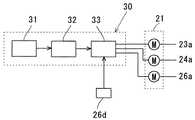
図3は、図1の食事動作支援ロボットにおける運動機能補助装置の構成を示すブロック図である。
上記制御部30は、図3に示すように、計測手段としての眼電図計測装置31と、使用者の意志情報を抽出する解析手段としてのDSPユニット32と、制御手段としてのサーボコントローラ33とから構成されている。駆動モータ23a,24a,26aは、DSPユニット32と力センサ26dからの信号により、サーボコントローラ33を介して駆動される。
【0026】
図4は、図3の運動機能補助装置における眼電図計測装置の具体的構成を示すもので、(A)は正面図、(B)は側面図である。
上記眼電図計測装置31は、図示するように、使用者11の装着感をできるだけ低減するために、メガネ型測定ユニットとして構成されている。
【0027】
図5は、図4の眼電図計測装置における電極位置を示す説明図である。使用者11がメガネを掛けるように当該メガネ型測定ユニットを装着したとき、例えば図5に示すように、使用者11の両眼11b,11cに関して、左眼11bの左側1.0cmの位置に第一の電極31a、右眼11cの右側1.0cmの位置に第二の電極31b、そして右眼11cの上下それぞれ3.0cmの位置に第三及び第四の電極31c,31dが配置されるようになっている。これにより、使用者11が食事の度に複数個の電極を顔面に装着する煩雑さ及び不快感から解放されることになる。
【0028】
上記解析手段としてのDSPユニット32は、計測手段としての眼電図計測装置31の各電極31a乃至31dからの検出電位に基づいて解析を行なって、使用者11の眼球運動を把握し、使用者11の眼球の注視位置を検出して、これを使用者の意志情報として抽出する。
【0029】
ここで、上記眼電図計測装置31の各電極31a乃至31dにより検出される電位をそれぞれX1,X2,X3,X4とすると、左右方向の電位差(X1−X2)及び上下方向の電位差(X3−X4)は、使用者11の左右方向及び上下方向の眼球運動を表わすことになり、これらの電位差(X1−X2)及び(X3−X4)に基づいて、上記DSPユニット32は、使用者11の眼球の上下左右の二次元平面上での運動を把握し、これを使用者の意志情報として抽出することができる。
【0030】
ここで、上記眼電図計測装置31の各電極31a乃至31dにより検出された電位X1,X2,X3,X4に基づいて、使用者11の眼球の運動を把握する実験例について参照して説明する。
図6は、図1の食事動作支援ロボットにおけるテーブル上に配置された皿の位置を示す概略図である。図示するように、テーブル13の上に、三つの皿41,42,43が並んで配置されている。そして、使用者11が、テーブル13上の自分が食べたい皿41,42または43を注視すると、使用者11の眼球運動が注視により実質的に静止することになる。
そこで、DSPユニット32が、この静止状態を検出することにより、そのときの眼球の方向に基づいて、使用者11がどの皿41,42または43を注視しているかを判定することができる。
【0031】
この判定アルゴリズムは、サッケード動作の検出,注視区間の検出そして注視点の判定の順に行なわれ、例えば以下のように構成されている。
第一に、注視点の移動を示すサッケード動作を検出する。
図7は、テーブル13上の基準点40または各皿41,42,43を注視しているときの眼電図、即ち眼球運動による水平方向の電位差(眼電図)Xh(t)=(X1−X2)及び垂直方向の電位差(眼電図)Xv(t)=(X3−X4)を、それぞれ+を上向きにて示している。
この場合、使用者11はまず基準点40を注視した後、いずれかの皿41,42または43を注視することとする。これにより、いずれの皿41,42または43を注視した場合にも、眼球は垂直方向に大きく動くので、垂直方向の眼電図Xh(t)は急峻な変化(所謂サッケード)を生ずることになる。その際、眼球が下方に動くことから、眼電図Xh(t)は少なくとも一時的に負の値となる。従って、区間[t0−1.0,t0+1.0]の2秒間における垂直方向の眼電図Xh(t)が最小値となる時刻をt0とし、この時刻t0を基準点40から皿41,42または43への移動の可能性が高い時刻とする。これにより、サッケード動作が検出されることになる。
【0032】
第二に、注視区間を検出する。
上述したサッケード動作の前後の注視中は、使用者11の眼球は基準点40あるいは皿41,42または43を注視していることから、眼球は実質的に静止しているが、実際には眼電図記録用の低域遮断フィルタの影響により緩やかな電位変動が生ずる。従って、DSPユニット32は、このような緩やかな電位変動を考慮して、注視区間を検出する。その際、上述したサッケード動作時t0以前には、使用者11が基準点40を注視していて眼電図Xv(t)の変動が少ないことから、眼電図Xv(t)が以下の二つの条件式
【数1】
【0033】
続いて、第三に、注視点の判定を行なう。
使用者11が基準点40から何れかの皿41,42または43を注視すると、垂直方向の眼電図Xv(t)だけでなく、水平方向の眼電図Xh(t)も変化する。従って、DSPユニット32は、これらの眼電図Xv(t)及びXh(t)の変化を捉えるために、以下の四つのパラメータ、
【数3】
ここで、Δtは、サンプリング間隔で、この場合10msに設定されている。式3は時刻t0以前の区間Bにおける垂直方向の眼電図Xv(t)の平均値、式4は時刻t0以後の区間C[t0+0.1,t0+1.1]における垂直方向の眼電図Xv(t)の平均値、また、式5及び6は、それぞれ区間B,Cにおける水平方向の眼電図Xh(t)の平均値を表わす。
使用者11の注視点が、基準点40から皿41,42または43に移動すると、上記式3及び4による垂直方向の眼電図Xv(t)の平均値の差が大きくなると共に、皿41,42または43は水平方向に距離をおいて一列に並んでいるので、水平方向の眼電図Xh(t)の平均値は、各注視点によって異なることになる。
【0034】
図8は、図3の運動機能補助装置におけるDSPユニットによる注視点の判定のためのしきい値を示す図である。
従って、DSPユニット32は、各皿41,42,43における注視点に関して、図8に示すように、垂直方向に関して式3及び4による垂直方向の眼電図Xv(t)の平均値の差αが50μV以上であるときに、且つ式5及び6による水平方向の眼電図Xh(t)の平均値の差βに応じて、注視点が皿41,42または43であると判定する。
即ち、DSPユニット32は、式5及び6による水平方向の眼電図Xh(t)の平均値の差βが−100μVから100μVでは注視点が皿41であると判定し、βが100μV以上では注視点が皿42であると判定し、さらにβが−100μV以下では、注視点が皿43であると判定する。
これに対して、これらの条件の何れも満たさない場合には、DSPユニット32は、何れの皿41,42または43も注視していないと判定する。
【0035】
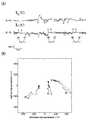
次に、上述した注視点の判定の具体的な実験結果を図9を参照して示す。図9は、図6の皿を使用者が順次に注視したときの、(A)は眼電図を示すグラフ、(B)は眼電図から得られる注視点の二次元平面上の位置を示す図である。
実験では、使用者11がそれぞれ基準点40の注視後それぞれ上記各皿41,42及び43を注視している。
図9(A)は、実験による使用者11の水平方向及び垂直方向の眼電図Xv(t)及びXh(t)を示しており、基準点40または皿41,42,43の注視区間において、各眼電図Xv(t)及びXh(t)がそれぞれサッケード動作を挟んで緩やかに変動しており、その座標位置は図6に示した皿41,42,43の配置に近似していることが分かる。また、図9(B)から、上記各皿41,42及び43の注視点により、二次元平面上の位置が変化していることが分かる。このようにして、使用者11の注視点を眼電図により判定し、具体的には使用者11がどの皿41,42,43を注視しているかを判定することが可能である。
【0036】
ところで、特許文献1においては、眼球運動により生ずる生体信号を検出して、ロボット等の機器を制御する方法が提案されているが、眼球がどの方向に移動しているかを検出するだけであって、眼球がどの方向にどの程度移動して、何れの方向に向いているかを判定することはできない。そのため、多彩な制御を行なうことは不可能であった。
これに対して、上述したように本発明の実施形態による運動機能補助装置30においては、使用者11の眼球運動の眼電図により、サッケード動作,注視動作そして電位に基づいて、使用者11の眼球運動を左右方向及び上下方向に関して検出し、注視点の二次元平面上の位置を判定するようにしているので、任意に配置された複数の注視点を区別して判定することができる。
【0037】
上記サーボコントローラ33は、DSPユニット32からの判定結果、即ち何れの皿41,42,43を注視しているかに基づいて自立支援ロボット機構21に対してコマンドを出力するようになっている。即ち、サーボコントローラ33は、使用者11の注視点である皿41,42または43に向かって使用者11の右手首11aを皿41,42または43に向かって移動させるように、各駆動モータ23a,24a,26aを駆動制御する。
【0038】
その際、自立支援ロボット機構21は、使用者11の右腕の筋力を補助する補助力のみを発生させると共に、この補助力によって使用者11に対して危害を加えないように、当該補助力が大きくなり過ぎた場合には、サーボコントローラ33は、駆動制御を切り換えて補助力を小さくすることにより、安全性を確保するようになっている。即ち、サーボコントローラ33は、自立支援ロボット機構21の第二のアーム26の先端のフック26cに備えられた力センサ26dの検出出力がフィードバックされており、この力センサ26dの検出出力によって、自立支援ロボット機構21の駆動制御にて使用者11の右手首11aに加えられる力を検出して、この力が所定値を超えたとき駆動制御を切り換えて、自立支援ロボット機構21の駆動制御により使用者11の右手首11aに加えられる力を低減するようになっている。
【0039】
このような補助力生成の制御手法の具体例について、図10を参照して説明する。図10は、図3の運動機能補助装置における制御手法を示すブロック図である。図10において、制御手法は五個のブロックに分かれており、使用者11の右腕を示す第一ブロック51、サーボコントローラ33と自立支援ロボット機構21を示す第二のブロック52、使用者11の右腕と自立支援ロボット機構21の連結部を示す第三のブロック53、注視点からサーボコントローラ33への入力を与える第四のブロック54、そして、上記安全性を確保するための第五のブロック55を備えている。そして、この制御手法においては、自立支援ロボット機構21の第二のアーム26の先端の移動速度を考慮しながら軌道制御を行なうことにより、補助力を生成するようになっている。
【0040】
ここで、まず符号A1で示すように、第四のブロック54にて、DSPユニット32により判定された注視点(眼電図情報EOG)が、目標点として入力される。
具体的には、自立支援ロボット機構21の第二のアーム26の先端の位置(現在点)をPR=(xR,yR,zR)、
入力された目標点をPdR=(xdR,ydR,zdR)とすると、二点間の距離は、
【数7】
【0041】
次に、図10にて符号A2で示すように、移動速度の大きさをvとして、現在点から目標点までのベクトルを求めて、自立支援ロボット機構21の第二のアーム26の先端の移動速度を導出する。
図11は、図10の制御手法における自立支援ロボット機構の第二のアームの先端の移動速度を示すグラフである。図において、横軸が時間(t)で、縦軸が速度Vである。即ち、二点間の移動速度の最大値をv0として、図11に示すような所謂台形型の移動速度vを求める。
具体的には、移動速度vの傾きをaとすると、二点間の移動速度vは、
【数8】
【数9】
これらの式9乃至11を、自立支援ロボット機構21のヤコビアンの逆行列(JR)−1を用いて、自立支援ロボット機構21の目標関節角速度に変換すると、目標関節角速度は、
【数12】
【0042】
次に、図10の符号A3で示すように、上記目標関節角速度の積分によって、支援ロボットを駆動するためのサーボコントローラ33への関節位置指令qdRを算出する。
具体的には、上記式12を
【数13】
【0043】
続いて、図10にて符号A4で示すように、自立支援ロボット機構21の第二のアーム26のトルクτRが生成され、使用者11から自立支援ロボット機構21に加えられる外乱トルクτHRを減算して、実際に自立支援ロボット機構21の第二のアーム26への入力トルクτuRを演算する。
具体的には、自立支援ロボット機構21の第二のアーム26の目標関節位置指令qdRと現在の関節位置qR、そして関節角速度q・Rを用いて、自立支援ロボット機構の第二のアーム26の関節に生成されるトルクτRは、
【数14】
さらに、使用者11の右腕から外乱トルクτHRを減算することにより、自立支援ロボット機構21に加えられる総トルクτuRは、
【数15】
【0044】
次に、図10の符号A5で示すように、上記入力トルクτuRにより、自立支援ロボット機構21が動作して、その第二のアーム26のアーム関節角度qRから当該自立支援ロボット機構21のキネマティクスによって、自立支援ロボット機構21のアーム先端位置PRに変換される。
ここで、自立支援ロボット機構21の動力学方程式は、一般的には
【数16】
従って、具体的には式15及び16により、自立支援ロボット機構21の動作を表現することが可能であり、式16から自立支援ロボット機構21の第二のアーム26のアーム関節位置qRが得られ、さらに自立支援ロボット機構21のキネマティクスにより、自立支援ロボット機構21の第二のアーム26の先端位置PRが得られることになる。
【0045】
次に、図10にて符号A6で示すように、自立支援ロボット機構21の動作がバネ・ダンパ(後述)を介して使用者11の右手首11aに伝達され、そのときの伝達力FRHが、力センサ26dにより得られる。
具体的には、自立支援ロボット機構21の第二のアーム26の先端位置PRと使用者11の右腕の先端位置PHとの距離をPeRHとすると、この距離は、
【数17】
【数18】
このようにして、自立支援ロボット機構21の駆動制御による動作が、バネ・ダンパを介して伝達力FRHとして使用者11の右腕に加えられることになる。
【0046】
次に、図10にて符号A7で示すように、バネ・ダンパを介して使用者11の右腕の先端にかかる自立支援ロボット機構21からの伝達力FRHを、使用者11の右腕のヤコビアン転置(JH)Tを用いて、使用者11の右腕の関節トルクτRHに変換する。
続いて、図10にて符号A8で示すように、使用者11が自ら出力した右腕の関節トルクτHと上記自立支援ロボット機構21による関節トルクτRHを加算して、使用者11の右腕にかかる総トルクτuHを算出する。
即ち、総トルクτuHは、
【数19】
【0047】
次に、図10にて符号A9で示すように、上記総トルクτuHによって、使用者11の右腕が動作するので、使用者11の右腕の関節角度qHから使用者11の右腕のキネマティクス変換によって、使用者11の右腕の先端位置PHを算出する。
即ち、使用者11の右腕を多関節のロボットアームとみなして、ラグランジュの運動方程式により、その動力学方程式を求めると、一般的に
【数20】
従って、式19及び20により、使用者11の右腕の動きを表現することが可能である。
【0048】
次に、図10にて符号A10で示すように、バネ・ダンパを介して自立支援ロボット機構21から使用者11の右腕に加えられたトルクτRHは、作用反作用の法則によって、使用者11の右腕から自立支援ロボット機構21にも加えられることになるため、伝達力FRHを自立支援ロボット機構21にフィードバックし、その際自立支援ロボット機構21のヤコビアン転置(JR)Tを用いて使用者11の右腕から自立支援ロボット機構21に加えられる伝達トルクτHRとなる。
即ち、式20に基づいて使用者11の右腕が動作すると、バネ・ダンパによる伝達力FRHが変化することにより、この伝達力FRHをヤコビアン転置(JR)Tによりフィードバックする自立支援ロボット機構21にも、伝達トルクτHRの影響を与えることになる。
【0049】
また、図10にて符号A11で示すように、使用者11が自ら発生したトルクτHによって、伝達力FRHの大きさも変化するので、フィードバックにより自立支援ロボット機構21に入力される外乱トルクτHRも変化することになる。
その際、外乱トルクτHRがある閾値を超えた場合、スイッチSwがフォースフリー制御に切り替わる。ここで、フォースフリー制御とは、外部から加えられた力に従って、対象となる装置を駆動させる公知の制御手法であって、この場合フォースフリー制御が、外乱トルクτHRに従って動作するようなサーボ系への関節位置指令を生成する。これによって、自立支援ロボット21を無重力・無摩擦な空間に存在しているかのように制御することにより、自立支援ロボット機構21が使用者11から離反するように動作することになり、使用者11の安全性が確保されることになる。
【0050】
このため、フォースフリー制御は、使用者11の右腕からのトルクτHRに基づいて、
【数21】
により与えられる。
このようにして、式21により得られた目標関節位置qdRは、第四のブロック54により生成された目標関節位置qdRと、スイッチSwにより排他的に切り替えられることにより、使用者11の右腕と自立支援ロボット機構21の間の力を逃がして、あるいは自立支援ロボット機構21が人間や物体等の外部環境が衝突した場合の安全性を確保することができる。
【0051】
本発明の実施形態による食事動作支援ロボット10は、以上のように構成されており、使用者11が食したい食物の載っている皿41,42または43を注視することによって、運動機能補助装置20が、使用者11の眼電図計測装置31により計測された眼電図に基づいて使用者11の注視点を検出し、サーボコントローラ33により自立支援ロボット機構21を駆動制御する。
これにより、使用者11が、自分の右手首を自立支援ロボット機構21により注視点となる皿41,42または43に向かって移動させようとする際に、自立支援ロボット機構21が使用者11の右手首を当該注視点に向かうような使用者11の右腕の運動を補助するように移動させる。この際、自立支援ロボット機構21の第二のアーム26の先端の移動速度を考慮しながら軌道制御を行なうことにより、過不足のない適切な補助力が生成できる。
これにより、力が弱すぎて十分な補助力が得られないということもなく、また、使用者に過剰な力が加わらないので安全である。従って、使用者11の右腕の筋力が低下していたとしても、使用者11は自らの意志に基づいて、右腕を注視点となる皿41,42または43に向かって移動させることができる。
さらに、使用者11に無理な力が加えられた場合には、フォースフリー制御に切り替えられることから、使用者11に危害が加えられてしまうようなことはなく、安全性が確保される。
【0052】
図12は、図10に関連して説明した補助力生成の制御手法の別の具体例を示すもので、図3の運動機能補助装置における制御手法の変形例を示すブロック図である。図12において、制御手法は、四個のブロックに分かれており、使用者11の右腕を示す第一ブロック61、サーボコントローラ33と自立支援ロボット機構21を示す第二のブロック62、使用者11の右腕と自立支援ロボット機構21の連結部を示す第三のブロック63、注視点からサーボコントローラ33への入力を与える第四のブロック64を備えている。
そして、この制御手法においては、自立支援ロボット機構21の第二のアーム26の先端を移動させるために必要なトルクを求めて、このトルクに基づいてフォースフリー制御を行なうことにより、補助力を生成するようになっている。
【0053】
ここで、まず符号B1で示すように、第四のブロック64にて、DSPユニット32により判定された注視点(眼電図情報EOG)が、目標点として入力される。具体的には、眼電図から得られた注視点を目標点として、この目標点と現在点から目標軌道PdH(x,y,z)を演算する。
【0054】
次に、図12にて符号B2で示すように、上記目標点に対応する目標関節位置qdRを逆キネマティックにより演算する。
具体的には、上記目標軌道PdH(x,y,z)から逆キネマティックを用いて、自立支援ロボット機構21の目標関節位置qdRは、
【数22】
【0055】
次に、図12にて符号B3で示すように、上記目標関節位置qdRから、自立支援ロボット機構21のラグランジュの運動方程式
【数25】
【0056】
続いて、図12にて符号B4で示すように、上記トルク指令τdRと使用者11から自立支援ロボット機構21に加えられるトルクτHRにより、フォースフリー制御によって、位置指令qdR*を生成して、自立支援ロボット機構21に入力する。
具体的には、上記トルク指令τdRと使用者11の右腕から自立支援ロボット機構21に加えられた力をトルクに変換したトルクτHRにより、自立支援ロボット機構21に必要なトルクτdR*を演算し、このトルクτdR*から、以下の式
【数26】
【0057】
次に、図12の符号B5で示すように、上記位置指令qdR*をサーボコントローラ33に入力して、自立支援ロボット機構21のラグランジュの運動方程式
【数28】
【0058】
次に、図12の符号B6で示すように、上記自立支援ロボット機構21の関節位置qRから、自立支援ロボット機構21の第二のアーム26の先端の軌跡PRをキネマティクス
【数29】
【0059】
次に、図12にて符号B7で示すように、バネ・ダンパによりモデル化して、バネ・ダンパを介して使用者11の右腕の先端にかかる自立支援ロボット機構21からの伝達力FRHを演算する。
即ち、自立支援ロボット機構21の第二のアーム26の先端位置PRと使用者11の右腕の先端位置PHから、
【数32】
【0060】
続いて、図12にて符号B8で示すように、使用者11の右腕に加えられる力FRHを、使用者11の右腕のヤコビアン転置(JH)Tを用いて、
【数34】
【0061】
次に、図12にて符号B9で示すように、上記使用者11の右腕の関節トルクτRHから、使用者の右腕のラグランジュの運動方程式
【数35】
【0062】
次に、図12にて符号B10により示すように、使用者11の右腕の関節位置qHから、使用者11の右腕の先端の軌跡PHを、キネマティクス変換
【数36】
【0063】
続いて、図12にて符号B11で示すように、使用者11が自ら発生したトルクτHによって、伝達力FRHの大きさも変化するので、フィードバックにより自立支援ロボット機構21に入力される外乱トルクτHRも変化することになる。その際、外乱トルクτHRがある閾値を超えた場合、スイッチSwが切り替わって、トルク指令τdRからの入力を遮断する。これにより、フォースフリー制御が、外乱トルクτHRに従って動作するようなサーボ系への関節位置指令を生成する。
これによって、自立支援ロボット21を無重力・無摩擦な空間に存在しているかのように制御することにより、自立支援ロボット機構21が使用者11から離反するように動作することになる。従って、使用者11の右腕と自立支援ロボット機構21の間の力を逃がして、あるいは自立支援ロボット機構21が人間や物体等の外部環境が衝突した場合の安全性を確保することができる。
【0064】
上述した実施形態においては、運動機能補助装置20は、使用者11の右腕の運動を補助する自立支援ロボット機構21を備えているが、これに限らず、使用者11の筋力低下の部位に応じて、適宜の運動機能補助装置を構成してもよいことは明らかである。
また、上述した実施形態においては、使用者11として寝たきり患者を想定しているが、これに限らず、例えば関節リウマチ等の一時的または慢性的に関節が痛むような患者、さらには高齢、筋ジストロフィーやALS等の全身の筋力が低下し運動が困難となった患者等も含むことは明らかである。
【0065】
【発明の効果】
以上述べたように、本発明によれば、使用者の自ら発生する筋力を補助する補助力を発生させることにより、使用者が筋力の低下した部位の運動を行なおうとする際に、その低下した筋力を補助するので、使用者本人が他人の介助なしに又は軽減して自分の意志で運動を行なうことができる。
その際、検出した眼球運動の上下方向及び左右方向の眼電図に基づいて、使用者の眼球の実質的な静止状態、即ち注視状態を検出することによって、眼球運動による二次元平面上の任意の座標位置を判定することができる。従って、使用者の注視点を確実に検出することによって、その座標位置に応じて多様な使用者の意志情報を検出することができる。
このようにして、本発明によれば、使用者本人が他人の介助なしに容易に自分の意志で運動を行なうことができるようにした、極めて優れた運動機能補助装置及び方法が提供される。
【図面の簡単な説明】
【図1】本発明による運動機能補助装置の一実施形態を組み込んだ食事動作支援ロボットの構成を示すもので、(A)は側面図、(B)は平面図である。
【図2】図1の食事動作支援ロボットにおける自立支援ロボット機構の構成を示すもので、(A)は側面図、(B)は平面図である。
【図3】図1の食事動作支援ロボットにおける運動機能補助装置の構成を示すブロック図である。
【図4】図3の運動機能補助装置における眼電図計測装置の具体的構成を示すもので、(A)は正面図、(B)は側面図である。
【図5】図4の眼電図計測装置における電極位置を示す説明図である。
【図6】図1の食事動作支援ロボットにおけるテーブル上に配置された皿の位置を示す概略図である。
【図7】図4の眼電図計測装置にて使用者が注視しているときの眼電図波形を示すグラフである。
【図8】図3の運動機能補助装置におけるDSPユニットによる注視点の判定のためのしきい値を示す図である。
【図9】図6の皿を使用者が順次に注視したときの、(A)は眼電図を示すグラフ、(B)は眼電図から得られる注視点の二次元平面上の位置を示す図である。
【図10】図3の運動機能補助装置における制御手法を示すブロック図である。
【図11】図10の制御手法における自立支援ロボット機構の第二のアームの先端の移動速度を示すグラフである。
【図12】図3の運動機能補助装置における制御手法の変形例を示すブロック図である。
【符号の説明】
10 食事動作支援ロボット
11 使用者
11a 右手首
11b 左眼
11c 右目
12 ベッド
13 テーブル
20 運動機能補助装置
21 自立支援ロボット機構
22 固定部
23 第一軸
24 第二軸
25 第一のアーム
26 第二のアーム
23a,24a,26a 駆動モータ
26b 駆動ベルト
26c フック
26d 力センサ
30 制御部
31 眼電図計測装置
31a,31b,31c,31d 電極
32 DSPユニット(解析手段)
33 サーボコントローラ(制御手段)
40 基準点
41,42,43 皿(注視点)
51,61 使用者の右腕を示す第一ブロック
52,62 サーボコントローラと自立支援ロボット機構を示す第二のブロック
53,63 使用者の右腕と自立支援ロボット機構の連結部を示す第三のブロック
54,64 注視点からサーボコントローラへの入力を与える第四のブロック
55 安全性を確保するための第五のブロック[0001]
TECHNICAL FIELD OF THE INVENTION
The present invention relates to a motor function assisting device and method for enhancing motor function of a person having reduced motor function.
[0002]
[Prior art]
In recent years, as the average life expectancy has increased, the number of elderly persons has increased remarkably, and with this, assistance for elderly persons and persons with motor dysfunction due to muscular weakness has become an important problem. On the other hand, various studies have been conducted for the purpose of dietary assistance and recovery / support of exercise function so that an elderly person or the like can perform a desired exercise on their own will without the assistance of another person.
[0003]
Such research is broadly classified into three research and development trends, the first is the development of substitute parts such as artificial hands, the second is the development of nursing care devices using robots, and the third is the so-called FES (Functional Electrical Stimulation). This is a study on the recovery of motor function due to such factors.
In particular, in the field of dietary assistance, a dietary assistance device in which the user operates a joystick with his / her chin and transports food to the mouth of the user by a robot is already on the market. However, in such an operation method using a jaw, skill is required to operate the joystick, and therefore, the user is stressed.
[0004]
On the other hand, a biosignal-based control device detects a biosignal generated by eye movement and generates a control signal for controlling devices such as a living device and a robot based on the biosignal. Is disclosed (see Patent Document 1). According to this, a biological signal generated by eye movement of a user is frequency-analyzed, and four types of basic signals are extracted based on relatively high-frequency components of 10 Hz or more. Then, 64 kinds of control signals are generated by combining these four kinds of basic signals arbitrarily.
[0005]
[Patent Document 1]
JP-A-2001-228949 (page 2-3, FIG. 1)
[0006]
[Problems to be solved by the invention]
However, in the control apparatus using a biological signal according to
Therefore, in such a method of detecting a biological signal, only the direction in which the eyeball moves up, down, left, or right is detected, and the amount of change in which direction the eyeball moves is detected. It is not possible. For this reason, for example, with 64 types of control signals, very fine control cannot be performed. For example, it is difficult to perform accurate control of a robot. It is limited to.
[0007]
In view of the above, it is an object of the present invention to provide a motor function assisting device and method that allow a user to easily exercise with his own will without the assistance of another person.
[0008]
[Means for Solving the Problems]
In order to achieve the above object, according to a first configuration of the present invention, a motor function assisting device including a driving unit that generates an auxiliary force that complements a user's muscular strength and a control unit that controls the driving unit. And measuring means for measuring a potential change due to vertical and horizontal eye movements obtained from an electrogram relating to the user, and extracting intention information of the user based on the vertical and horizontal potential changes Analyzing means for controlling the driving means based on the intention information extracted by the analyzing means to assist the motor function of the user. .
[0009]
In the motor function assisting device according to the present invention, preferably, the analysis means determines the direction of the user's gaze as the intention of the user.
[0010]
In the motor assisting device according to the present invention, preferably, the measuring means calculates a relative position of the eyeball based on a potential change due to eye movement, and the analyzing means extracts a gaze position by the eyeball as user's intention information. I do.
[0011]
In the motor assisting device according to the present invention, preferably, when the control means drives and controls the motor assisting unit, the control means generates an assisting force by trajectory control considering speed.
[0012]
In the motor assisting device according to the present invention, preferably, the control means generates an assisting force by force-free control when driving and controlling the motor assisting unit.
[0013]
In the motor function assisting device according to the present invention, preferably, when the control means drives and controls the motor function assisting unit, force-free control is performed by a force sensor so that an excessive force is not applied to the user.
[0014]
According to a second aspect of the present invention, there is provided a first step of measuring a potential change due to eye movement in a vertical direction and a horizontal direction obtained by an electrocardiogram relating to a user, Based on the change in the potential in the left-right direction, the second stage to extract the user's will, characterized in that the motor function assist unit is driven and controlled based on this will to assist the user's motor function, Achieved by motor function assisting methods.
[0015]
According to the above configuration, the potential change of the user's eye movements in the up, down, left, and right directions is measured, and the intention information of the user is extracted based on the potential change due to the eye movement, for example, by extracting the gazing point. By driving and controlling the motor function assisting unit based on the user's intention, an assisting force can be generated by the motor function assisting unit in accordance with the user's will to assist the user's exercise.
[0016]
Therefore, according to the present invention, by generating an assisting force for assisting the user's own generated muscle strength, the user can assist the reduced muscle strength when the user attempts to exercise a part where the muscle strength is reduced. Therefore, the user himself / herself can easily exercise with his / her own will without the assistance of another person.
At this time, based on the detected electro-oculograms in the vertical and horizontal directions of the eye movement, the user detects the substantially stationary state of the eyeball of the user, that is, the state of fixation, thereby detecting any state on the two-dimensional plane due to the eye movement. Can be extracted and determined by the analysis means. Therefore, it is possible to reliably detect the point of gaze of the user and detect various user's intention information according to the coordinate position.
[0017]
When the measuring means calculates the relative position of the eyeball based on the potential change due to the eyeball movement, and the analyzing means extracts the gaze position by the eyeball as the user's intention information, the vertical direction by the eyeball movement of the user By calculating the relative position in the horizontal direction, the gaze position can be easily extracted accurately on a two-dimensional plane.
[0018]
When the control means generates an assisting force by trajectory control considering speed when driving and controlling the motor function assisting section, it is possible for the user to generate an appropriate assisting force without excess or deficiency. It is.
[0019]
When the control means generates an assisting force by force-free control when driving and controlling the motor function assisting unit, the motor function assisting unit is used when the external force of a user or a human or an object collides. Since the operation of the unit is performed so as to separate from the user, the safety of the user is ensured.
[0020]
When the control means performs force-free control with a force sensor so as not to apply an excessive force to the user when driving and controlling the motor function assisting section, the control means is similarly used by driving the motor function assisting section. No excessive force is applied to the user, and the safety of the user is ensured.
[0021]
BEST MODE FOR CARRYING OUT THE INVENTION
Hereinafter, the present invention will be described in detail based on embodiments shown in the drawings.
FIGS. 1 and 2 show the configuration of an embodiment of a robot that supports a meal operation as an example by applying the motor function assisting device according to the present invention.
FIGS. 1A and 1B show a configuration of a meal motion support robot incorporating one embodiment of a motor function assisting device according to the present invention, wherein FIG. 1A is a side view and FIG. 1B is a plan view.
In FIG. 1, a meal
[0022]
The
The table 13 is supported on the
[0023]
The motor
2A and 2B show the configuration of the self-supporting robot mechanism in the eating operation supporting robot of FIG. 1, wherein FIG. 2A is a side view and FIG. 2B is a plan view. As shown in FIG. 2, a
[0024]
The
[0025]
FIG. 3 is a block diagram showing a configuration of a motor function assisting device in the eating operation support robot of FIG.
As shown in FIG. 3, the
[0026]
4A and 4B show a specific configuration of the electro-oculogram measuring device in the motor function assisting device of FIG. 3, wherein FIG. 4A is a front view and FIG. 4B is a side view.
As shown in the figure, the
[0027]
FIG. 5 is an explanatory diagram showing electrode positions in the electrocardiogram measuring device of FIG. When the
[0028]
The
[0029]
Here, the potentials detected by the
[0030]
Here, the potential X detected by each of the
FIG. 6 is a schematic diagram showing the position of a dish placed on a table in the eating operation support robot of FIG. As shown in the figure, on the table 13, three
Therefore, by detecting this stationary state, the
[0031]
This determination algorithm is performed in the order of saccade motion detection, gaze section detection, and gaze point determination, and is configured, for example, as follows.
First, a saccade operation indicating the movement of the point of interest is detected.
FIG. 7 shows an electrocardiogram when the user is gazing at the
In this case, the
[0032]
Second, the gaze section is detected.
During the gaze before and after the above-mentioned saccade operation, the eyeball of the
(Equation 1)
[0033]
Subsequently, third, a gazing point is determined.
When the
(Equation 3)
Here, Δt is a sampling interval, and in this case, is set to 10 ms.
When the gazing point of the
[0034]
FIG. 8 is a diagram showing threshold values for determining a gazing point by the DSP unit in the motor function assisting device of FIG.
Therefore, as shown in FIG. 8, the
That is, the
On the other hand, when none of these conditions is satisfied, the
[0035]
Next, a specific experiment result of the above-described determination of the point of gaze will be described with reference to FIG. 9A is a graph showing an electrocardiogram when the user gazes at the dish of FIG. 6 sequentially, and FIG. 9B shows a position on a two-dimensional plane of a gazing point obtained from the electrocardiogram. FIG.
In the experiment, the
FIG. 9 (A) shows an electro-oculogram X in the horizontal direction and the vertical direction of the
[0036]
By the way,
On the other hand, as described above, in the motor
[0037]
The
[0038]
At this time, the self-supporting
[0039]
A specific example of such an assisting force generation control method will be described with reference to FIG. FIG. 10 is a block diagram showing a control method in the motor function assisting device of FIG. In FIG. 10, the control method is divided into five blocks, a
[0040]
Here, first, as indicated by reference numeral A1, in the
Specifically, the position (current point) of the tip of the
Set the input target point to PdR= (XdR, YdR, ZdR), The distance between the two points is
(Equation 7)
[0041]
Next, as indicated by reference numeral A2 in FIG. 10, a vector from the current point to the target point is obtained with the magnitude of the moving speed as v, and the tip of the
FIG. 11 is a graph showing the moving speed of the tip of the second arm of the self-supporting robot mechanism in the control method of FIG. In the figure, the horizontal axis is time (t) and the vertical axis is speed V. That is, the maximum value of the moving speed between two points is represented by v0Then, a so-called trapezoidal moving speed v as shown in FIG. 11 is obtained.
Specifically, assuming that the inclination of the moving speed v is a, the moving speed v between the two points is
(Equation 8)
(Equation 9)
These equations 9 to 11 are converted into the Jacobian inverse matrix (JR)-1Is converted into the target joint angular velocity of the self-supporting
(Equation 12)
[0042]
Next, as indicated by reference numeral A3 in FIG. 10, the joint position command q to the
Specifically, the
(Equation 13)
[0043]
Subsequently, as indicated by reference numeral A4 in FIG. 10, the torque τ of the
Specifically, the target joint position command q of the
[Equation 14]
Further, the disturbance torque τ is applied from the right arm of the user 11.HRIs subtracted to obtain the total torque τ applied to the self-supporting
[Equation 15]
[0044]
Next, as shown by reference numeral A5 in FIG.uRAs a result, the self-supporting
Here, the dynamic equation of the self-supporting
(Equation 16)
Therefore, specifically, the operation of the self-supporting
[0045]
Next, as shown by reference numeral A6 in FIG. 10, the operation of the self-supporting
Specifically, the tip position P of the
[Equation 17]
(Equation 18)
In this manner, the operation by the drive control of the self-supporting
[0046]
Next, as indicated by reference numeral A7 in FIG. 10, the transmission force F from the self-supporting
Subsequently, as shown by reference numeral A8 in FIG. 10, the joint torque τ of the right arm output by the
That is, the total torque τuHIs
[Equation 19]
[0047]
Next, as indicated by reference numeral A9 in FIG.uHAs a result, the right arm of the
That is, when the right arm of the
(Equation 20)
Therefore, the movement of the right arm of the
[0048]
Next, as indicated by reference numeral A10 in FIG. 10, the torque τ applied to the right arm of the
That is, when the right arm of the
[0049]
Further, as shown by reference numeral A11 in FIG.HThe transmission force FRHOf the disturbance torque τ input to the self-
At that time, the disturbance torque τHRWhen a certain threshold value is exceeded, the switch Sw switches to force-free control. Here, the force-free control is a known control method for driving a target device in accordance with an externally applied force. In this case, the force-free control is performed by using a disturbance torque τ.HRA joint position command to the servo system that operates in accordance with the following is generated. As a result, by controlling the self-supporting
[0050]
For this reason, the force-free control uses the torque τ from the right arm of the user 11.HROn the basis of the,
(Equation 21)
Given by
Thus, the target joint position q obtained by
[0051]
The eating
Thus, when the
As a result, there is no possibility that a sufficient assisting force cannot be obtained due to too weak force, and the user is safe because no excessive force is applied to the user. Therefore, even if the muscular strength of the right arm of the
Further, when an excessive force is applied to the
[0052]
FIG. 12 is a block diagram showing another specific example of the control method for generating the assisting force described with reference to FIG. 10 and showing a modified example of the control method in the motor function assisting device of FIG. In FIG. 12, the control method is divided into four blocks, a
In this control method, a torque required to move the tip of the
[0053]
Here, first, as indicated by reference numeral B1, in the
[0054]
Next, as indicated by reference numeral B2 in FIG. 12, the target joint position q corresponding to the target pointdRIs calculated by inverse kinematics.
Specifically, the target trajectory PdHFrom (x, y, z), using inverse kinematics, the target joint position q of the self-supporting
(Equation 22)
[0055]
Next, as indicated by reference numeral B3 in FIG.dRFrom the Lagrangian equation of motion of the self-
(Equation 25)
[0056]
Subsequently, as indicated by reference numeral B4 in FIG.dRΤ applied from the
Specifically, the torque command τdRAnd a torque τ obtained by converting a force applied from the right arm of the
(Equation 26)
[0057]
Next, as shown by reference numeral B5 in FIG.dR *Is input to the
[Equation 28]
[0058]
Next, as shown by reference numeral B6 in FIG.ROf the tip of the
(Equation 29)
[0059]
Next, as indicated by reference numeral B7 in FIG. 12, a model is formed by a spring / damper, and the transmission force F from the self-
That is, the tip position P of the
(Equation 32)
[0060]
Subsequently, as indicated by reference numeral B8 in FIG. 12, the force F applied to the right arm of the
[Equation 34]
[0061]
Next, as shown by reference numeral B9 in FIG. 12, the joint torque τ of the right arm of the
(Equation 35)
[0062]
Next, as indicated by reference numeral B10 in FIG. 12, the joint position q of the right arm of the
[Equation 36]
[0063]
Subsequently, as shown by reference numeral B11 in FIG.HThe transmission force FRHOf the disturbance torque τ input to the self-
As a result, by controlling the self-supporting
[0064]
In the embodiment described above, the motor
Further, in the above-described embodiment, a bedridden patient is assumed as the
[0065]
【The invention's effect】
As described above, according to the present invention, by generating an assisting force that assists the user's own generated muscle strength, when the user attempts to exercise a part where the muscle strength is reduced, the decrease is reduced. Since the assisted muscle strength is provided, the user can exercise with his or her own volition without or with the assistance of another person.
At this time, based on the detected electro-oculograms in the vertical and horizontal directions of the eye movement, the user detects the substantially stationary state of the eyeball of the user, that is, the state of fixation, thereby detecting any state on the two-dimensional plane due to the eye movement. Can be determined. Therefore, by reliably detecting the point of gaze of the user, it is possible to detect various user's intention information according to the coordinate position.
Thus, according to the present invention, there is provided an extremely excellent exercise function assisting device and method, which enable the user to easily exercise with his or her own will without the assistance of another person.
[Brief description of the drawings]
FIG. 1 shows a configuration of a meal motion assisting robot incorporating an embodiment of a motor function assisting device according to the present invention, wherein (A) is a side view and (B) is a plan view.
FIGS. 2A and 2B are diagrams showing a configuration of a self-supporting robot mechanism in the eating operation supporting robot of FIG. 1, wherein FIG. 2A is a side view and FIG.
FIG. 3 is a block diagram showing a configuration of a motor function assisting device in the eating operation support robot of FIG. 1;
4A and 4B show a specific configuration of an electro-oculogram measuring device in the motor function assisting device of FIG. 3, wherein FIG. 4A is a front view and FIG. 4B is a side view.
FIG. 5 is an explanatory diagram showing electrode positions in the electrocardiogram measuring device of FIG.
FIG. 6 is a schematic diagram showing a position of a dish arranged on a table in the eating operation support robot of FIG. 1;
FIG. 7 is a graph showing an electro-oculogram waveform when the user is gazing at the electro-oculography measurement device of FIG. 4;
FIG. 8 is a diagram showing threshold values for determining a gazing point by a DSP unit in the motor function assisting device of FIG. 3;
9A is a graph showing an electrogram, and FIG. 9B is a diagram showing a position on a two-dimensional plane of a gazing point obtained from the electrogram when the user looks at the dish of FIG. 6 sequentially. FIG.
FIG. 10 is a block diagram showing a control method in the motor function assisting device of FIG. 3;
11 is a graph showing the moving speed of the tip of the second arm of the self-supporting robot mechanism in the control method shown in FIG. 10;
FIG. 12 is a block diagram showing a modification of the control method in the motor function assisting device of FIG. 3;
[Explanation of symbols]
10 Eating operation support robot
11 User
11a Right wrist
11b Left eye
11c Right eye
12 beds
13 Table
20 Motor function assist device
21 Independence support robot mechanism
22 Fixed part
23 First axis
24 Second axis
25 First Arm
26 Second arm
23a, 24a, 26a drive motor
26b drive belt
26c hook
26d force sensor
30 control unit
31 EOG measurement device
31a, 31b, 31c, 31d electrodes
32 DSP unit (analysis means)
33 Servo controller (control means)
40 reference points
41, 42, 43 dishes (gaze point)
51, 61 First block showing the right arm of the user
52, 62 Second block showing servo controller and self-support robot mechanism
53, 63 A third block showing a connecting portion between the right arm of the user and the self-supporting robot mechanism.
54, 64 Fourth block giving input to the servo controller from the gazing point
55 Fifth Block for Ensuring Security
Claims (7)
Translated fromJapanese使用者に関する眼電図で得られた上下及び左右方向の眼球運動による電位変化を計測する計測手段と、
この上下方向及び左右方向の電位変化に基づいて、使用者の意志情報を抽出する解析手段と、
を備えており、
上記制御手段が、この解析手段により抽出された意志情報に基づいて駆動手段を駆動制御して、使用者の運動機能を補助することを特徴とする、運動機能補助装置。A motor function assisting device including a driving unit that generates an auxiliary force that complements a muscle force of a user, and a control unit that controls the driving unit,
Measurement means for measuring a potential change due to eye movement in the up and down and left and right directions obtained in the electrogram about the user,
Analysis means for extracting user's will information based on the vertical and horizontal potential changes;
With
A motor function assisting device characterized in that the control means drives and controls the driving means based on the will information extracted by the analyzing means to assist the motor function of the user.
この上下方向及び左右方向の電位変化に基づいて、使用者の意志を抽出する第二の段階と、
この意志に基づいて、運動機能補助部を駆動制御して、使用者の運動機能を補助することを特徴とする、運動機能補助方法。A first step of measuring a potential change due to eye movement in the up and down and left and right directions obtained in an electrogram about the user,
A second step of extracting the user's will based on the vertical and horizontal potential changes;
A motor function assisting method characterized in that the motor function assistant is driven and controlled based on the intention to assist the user's motor function.
Priority Applications (1)
| Application Number | Priority Date | Filing Date | Title |
|---|---|---|---|
| JP2003048314AJP4120008B2 (en) | 2003-02-25 | 2003-02-25 | Motor function assist device |
Applications Claiming Priority (1)
| Application Number | Priority Date | Filing Date | Title |
|---|---|---|---|
| JP2003048314AJP4120008B2 (en) | 2003-02-25 | 2003-02-25 | Motor function assist device |
Publications (2)
| Publication Number | Publication Date |
|---|---|
| JP2004254876Atrue JP2004254876A (en) | 2004-09-16 |
| JP4120008B2 JP4120008B2 (en) | 2008-07-16 |
Family
ID=33114299
Family Applications (1)
| Application Number | Title | Priority Date | Filing Date |
|---|---|---|---|
| JP2003048314AExpired - Fee RelatedJP4120008B2 (en) | 2003-02-25 | 2003-02-25 | Motor function assist device |
Country Status (1)
| Country | Link |
|---|---|
| JP (1) | JP4120008B2 (en) |
Cited By (7)
| Publication number | Priority date | Publication date | Assignee | Title |
|---|---|---|---|---|
| WO2010140975A1 (en)* | 2009-06-02 | 2010-12-09 | Agency For Science, Technology And Research | A system and method for motor learning |
| CN103182159A (en)* | 2012-08-30 | 2013-07-03 | 胡琦逸 | Lower limb rehabilitation training device based on electro-oculogram signal control |
| EP2668898A1 (en) | 2012-05-29 | 2013-12-04 | Jin Co., Ltd. | Eyewear |
| WO2014098494A1 (en)* | 2012-12-20 | 2014-06-26 | 한국과학기술연구원 | Apparatus for controlling prosthetic arm |
| JP2015027730A (en)* | 2006-07-17 | 2015-02-12 | レイセオン カンパニー | Robot displacement device |
| JP2015514251A (en)* | 2012-03-22 | 2015-05-18 | センソモトリック インストゥルメンツ ゲゼルシャフト フューア イノヴァティヴ センソリク エムビーエイチ | Method and apparatus for evaluating eye tracking results |
| US12138018B2 (en) | 2019-09-16 | 2024-11-12 | Nokia Technologies Oy | Eyewear device |
- 2003
- 2003-02-25JPJP2003048314Apatent/JP4120008B2/ennot_activeExpired - Fee Related
Cited By (12)
| Publication number | Priority date | Publication date | Assignee | Title |
|---|---|---|---|---|
| JP2015027730A (en)* | 2006-07-17 | 2015-02-12 | レイセオン カンパニー | Robot displacement device |
| WO2010140975A1 (en)* | 2009-06-02 | 2010-12-09 | Agency For Science, Technology And Research | A system and method for motor learning |
| US9125788B2 (en) | 2009-06-02 | 2015-09-08 | Agency For Science Technology And Research | System and method for motor learning |
| JP2015514251A (en)* | 2012-03-22 | 2015-05-18 | センソモトリック インストゥルメンツ ゲゼルシャフト フューア イノヴァティヴ センソリク エムビーエイチ | Method and apparatus for evaluating eye tracking results |
| EP2668898A1 (en) | 2012-05-29 | 2013-12-04 | Jin Co., Ltd. | Eyewear |
| EP2926729A1 (en) | 2012-05-29 | 2015-10-07 | Jin Co., Ltd. | Apparatus and method for processing eye potential |
| US9433369B2 (en) | 2012-05-29 | 2016-09-06 | Jin Co., Ltd. | Eyewear |
| US9706941B2 (en) | 2012-05-29 | 2017-07-18 | Jin Co., Ltd. | Eyewear |
| CN103182159A (en)* | 2012-08-30 | 2013-07-03 | 胡琦逸 | Lower limb rehabilitation training device based on electro-oculogram signal control |
| WO2014098494A1 (en)* | 2012-12-20 | 2014-06-26 | 한국과학기술연구원 | Apparatus for controlling prosthetic arm |
| US10166122B2 (en) | 2012-12-20 | 2019-01-01 | Korea Institute Of Science And Technology | Apparatus for controlling prosthetic arm |
| US12138018B2 (en) | 2019-09-16 | 2024-11-12 | Nokia Technologies Oy | Eyewear device |
Also Published As
| Publication number | Publication date |
|---|---|
| JP4120008B2 (en) | 2008-07-16 |
Similar Documents
| Publication | Publication Date | Title |
|---|---|---|
| JP6742196B2 (en) | Life activity detection device and life activity detection system | |
| JP4686681B2 (en) | Walking assistance system | |
| KR101221046B1 (en) | Intellectual exoskeleton robot system for assisting daily life and rehabilitation training | |
| EP2379041B1 (en) | Transfer assist apparatus | |
| Liu et al. | A home-based bilateral rehabilitation system with sEMG-based real-time variable stiffness | |
| Sarac et al. | Brain computer interface based robotic rehabilitation with online modification of task speed | |
| JP6759496B2 (en) | EEG pattern classification device, EEG pattern classification method, EEG pattern classification program and neurofeedback system | |
| WO2015044851A2 (en) | Physiological parameter measurement and feedback system | |
| JP6340528B2 (en) | BMI exercise assist device | |
| CN106618965A (en) | Wearable extremity rehabilitation training system and control method | |
| CA2584612A1 (en) | Motor training with brain plasticity | |
| WO2007128225A1 (en) | Robotic system and training method for rehabilitation using emg signals to provide mechanical help | |
| Hussain | State-of-the-art robotic gait rehabilitation orthoses: design and control aspects | |
| Badesa et al. | Dynamic adaptive system for robot-assisted motion rehabilitation | |
| Wehner | Man to machine, applications in electromyography | |
| JP5057314B2 (en) | Gait evaluation system and gait evaluation method | |
| Guo et al. | Human–robot interaction for rehabilitation robotics | |
| Banerjee et al. | Single channel electrooculogram (EOG) based interface for mobility aid | |
| Alaoui et al. | Using generic upper-body movement strategies in a free walking setting to detect gait initiation intention in a lower-limb exoskeleton | |
| JP2006263460A (en) | Rehabilitation support device | |
| JP2004254876A (en) | Motor function assisting device and method | |
| EP3167798A1 (en) | Biological signal measuring device, biological signal measuring method, mounted-type motion assist device, and motion assist method | |
| Jakopin et al. | An unobtrusive measurement method for assessing physiological response in physical human–robot interaction | |
| CN113905781A (en) | BioSpine: a digital twin neurorehabilitation system | |
| De Carli et al. | Measuring intent in human-robot cooperative manipulation |
Legal Events
| Date | Code | Title | Description |
|---|---|---|---|
| A621 | Written request for application examination | Free format text:JAPANESE INTERMEDIATE CODE: A621 Effective date:20041210 | |
| A131 | Notification of reasons for refusal | Free format text:JAPANESE INTERMEDIATE CODE: A131 Effective date:20071204 | |
| A521 | Written amendment | Free format text:JAPANESE INTERMEDIATE CODE: A523 Effective date:20080204 | |
| TRDD | Decision of grant or rejection written | ||
| A01 | Written decision to grant a patent or to grant a registration (utility model) | Free format text:JAPANESE INTERMEDIATE CODE: A01 Effective date:20080401 | |
| A61 | First payment of annual fees (during grant procedure) | Free format text:JAPANESE INTERMEDIATE CODE: A61 Effective date:20080411 | |
| FPAY | Renewal fee payment (event date is renewal date of database) | Free format text:PAYMENT UNTIL: 20110509 Year of fee payment:3 | |
| R150 | Certificate of patent or registration of utility model | Free format text:JAPANESE INTERMEDIATE CODE: R150 | |
| LAPS | Cancellation because of no payment of annual fees |