JP2004254811A - Artificial knee joint - Google Patents
Artificial knee jointDownload PDFInfo
- Publication number
- JP2004254811A JP2004254811AJP2003047009AJP2003047009AJP2004254811AJP 2004254811 AJP2004254811 AJP 2004254811AJP 2003047009 AJP2003047009 AJP 2003047009AJP 2003047009 AJP2003047009 AJP 2003047009AJP 2004254811 AJP2004254811 AJP 2004254811A
- Authority
- JP
- Japan
- Prior art keywords
- sliding surface
- tibial component
- knee joint
- component
- femoral component
- Prior art date
- Legal status (The legal status is an assumption and is not a legal conclusion. Google has not performed a legal analysis and makes no representation as to the accuracy of the status listed.)
- Granted
Links
Images


Classifications
- A—HUMAN NECESSITIES
- A61—MEDICAL OR VETERINARY SCIENCE; HYGIENE
- A61F—FILTERS IMPLANTABLE INTO BLOOD VESSELS; PROSTHESES; DEVICES PROVIDING PATENCY TO, OR PREVENTING COLLAPSING OF, TUBULAR STRUCTURES OF THE BODY, e.g. STENTS; ORTHOPAEDIC, NURSING OR CONTRACEPTIVE DEVICES; FOMENTATION; TREATMENT OR PROTECTION OF EYES OR EARS; BANDAGES, DRESSINGS OR ABSORBENT PADS; FIRST-AID KITS
- A61F2/00—Filters implantable into blood vessels; Prostheses, i.e. artificial substitutes or replacements for parts of the body; Appliances for connecting them with the body; Devices providing patency to, or preventing collapsing of, tubular structures of the body, e.g. stents
- A61F2/02—Prostheses implantable into the body
- A61F2/30—Joints
- A61F2/38—Joints for elbows or knees
- A61F2/3859—Femoral components
- A—HUMAN NECESSITIES
- A61—MEDICAL OR VETERINARY SCIENCE; HYGIENE
- A61F—FILTERS IMPLANTABLE INTO BLOOD VESSELS; PROSTHESES; DEVICES PROVIDING PATENCY TO, OR PREVENTING COLLAPSING OF, TUBULAR STRUCTURES OF THE BODY, e.g. STENTS; ORTHOPAEDIC, NURSING OR CONTRACEPTIVE DEVICES; FOMENTATION; TREATMENT OR PROTECTION OF EYES OR EARS; BANDAGES, DRESSINGS OR ABSORBENT PADS; FIRST-AID KITS
- A61F2/00—Filters implantable into blood vessels; Prostheses, i.e. artificial substitutes or replacements for parts of the body; Appliances for connecting them with the body; Devices providing patency to, or preventing collapsing of, tubular structures of the body, e.g. stents
- A61F2/02—Prostheses implantable into the body
- A61F2/30—Joints
- A61F2/38—Joints for elbows or knees
- A61F2/389—Tibial components
- A—HUMAN NECESSITIES
- A61—MEDICAL OR VETERINARY SCIENCE; HYGIENE
- A61F—FILTERS IMPLANTABLE INTO BLOOD VESSELS; PROSTHESES; DEVICES PROVIDING PATENCY TO, OR PREVENTING COLLAPSING OF, TUBULAR STRUCTURES OF THE BODY, e.g. STENTS; ORTHOPAEDIC, NURSING OR CONTRACEPTIVE DEVICES; FOMENTATION; TREATMENT OR PROTECTION OF EYES OR EARS; BANDAGES, DRESSINGS OR ABSORBENT PADS; FIRST-AID KITS
- A61F2/00—Filters implantable into blood vessels; Prostheses, i.e. artificial substitutes or replacements for parts of the body; Appliances for connecting them with the body; Devices providing patency to, or preventing collapsing of, tubular structures of the body, e.g. stents
- A61F2/02—Prostheses implantable into the body
- A61F2/30—Joints
- A61F2002/30001—Additional features of subject-matter classified in A61F2/28, A61F2/30 and subgroups thereof
- A61F2002/30316—The prosthesis having different structural features at different locations within the same prosthesis; Connections between prosthetic parts; Special structural features of bone or joint prostheses not otherwise provided for
- A61F2002/30535—Special structural features of bone or joint prostheses not otherwise provided for
- A61F2002/30604—Special structural features of bone or joint prostheses not otherwise provided for modular
- A—HUMAN NECESSITIES
- A61—MEDICAL OR VETERINARY SCIENCE; HYGIENE
- A61F—FILTERS IMPLANTABLE INTO BLOOD VESSELS; PROSTHESES; DEVICES PROVIDING PATENCY TO, OR PREVENTING COLLAPSING OF, TUBULAR STRUCTURES OF THE BODY, e.g. STENTS; ORTHOPAEDIC, NURSING OR CONTRACEPTIVE DEVICES; FOMENTATION; TREATMENT OR PROTECTION OF EYES OR EARS; BANDAGES, DRESSINGS OR ABSORBENT PADS; FIRST-AID KITS
- A61F2/00—Filters implantable into blood vessels; Prostheses, i.e. artificial substitutes or replacements for parts of the body; Appliances for connecting them with the body; Devices providing patency to, or preventing collapsing of, tubular structures of the body, e.g. stents
- A61F2/02—Prostheses implantable into the body
- A61F2/30—Joints
- A61F2/30767—Special external or bone-contacting surface, e.g. coating for improving bone ingrowth
- A61F2/30771—Special external or bone-contacting surface, e.g. coating for improving bone ingrowth applied in original prostheses, e.g. holes or grooves
- A61F2002/30878—Special external or bone-contacting surface, e.g. coating for improving bone ingrowth applied in original prostheses, e.g. holes or grooves with non-sharp protrusions, for instance contacting the bone for anchoring, e.g. keels, pegs, pins, posts, shanks, stems, struts
- A—HUMAN NECESSITIES
- A61—MEDICAL OR VETERINARY SCIENCE; HYGIENE
- A61F—FILTERS IMPLANTABLE INTO BLOOD VESSELS; PROSTHESES; DEVICES PROVIDING PATENCY TO, OR PREVENTING COLLAPSING OF, TUBULAR STRUCTURES OF THE BODY, e.g. STENTS; ORTHOPAEDIC, NURSING OR CONTRACEPTIVE DEVICES; FOMENTATION; TREATMENT OR PROTECTION OF EYES OR EARS; BANDAGES, DRESSINGS OR ABSORBENT PADS; FIRST-AID KITS
- A61F2310/00—Prostheses classified in A61F2/28 or A61F2/30 - A61F2/44 being constructed from or coated with a particular material
- A61F2310/00005—The prosthesis being constructed from a particular material
- A61F2310/00011—Metals or alloys
- A61F2310/00017—Iron- or Fe-based alloys, e.g. stainless steel
- A—HUMAN NECESSITIES
- A61—MEDICAL OR VETERINARY SCIENCE; HYGIENE
- A61F—FILTERS IMPLANTABLE INTO BLOOD VESSELS; PROSTHESES; DEVICES PROVIDING PATENCY TO, OR PREVENTING COLLAPSING OF, TUBULAR STRUCTURES OF THE BODY, e.g. STENTS; ORTHOPAEDIC, NURSING OR CONTRACEPTIVE DEVICES; FOMENTATION; TREATMENT OR PROTECTION OF EYES OR EARS; BANDAGES, DRESSINGS OR ABSORBENT PADS; FIRST-AID KITS
- A61F2310/00—Prostheses classified in A61F2/28 or A61F2/30 - A61F2/44 being constructed from or coated with a particular material
- A61F2310/00005—The prosthesis being constructed from a particular material
- A61F2310/00011—Metals or alloys
- A61F2310/00023—Titanium or titanium-based alloys, e.g. Ti-Ni alloys
- A—HUMAN NECESSITIES
- A61—MEDICAL OR VETERINARY SCIENCE; HYGIENE
- A61F—FILTERS IMPLANTABLE INTO BLOOD VESSELS; PROSTHESES; DEVICES PROVIDING PATENCY TO, OR PREVENTING COLLAPSING OF, TUBULAR STRUCTURES OF THE BODY, e.g. STENTS; ORTHOPAEDIC, NURSING OR CONTRACEPTIVE DEVICES; FOMENTATION; TREATMENT OR PROTECTION OF EYES OR EARS; BANDAGES, DRESSINGS OR ABSORBENT PADS; FIRST-AID KITS
- A61F2310/00—Prostheses classified in A61F2/28 or A61F2/30 - A61F2/44 being constructed from or coated with a particular material
- A61F2310/00005—The prosthesis being constructed from a particular material
- A61F2310/00011—Metals or alloys
- A61F2310/00029—Cobalt-based alloys, e.g. Co-Cr alloys or Vitallium
- A—HUMAN NECESSITIES
- A61—MEDICAL OR VETERINARY SCIENCE; HYGIENE
- A61F—FILTERS IMPLANTABLE INTO BLOOD VESSELS; PROSTHESES; DEVICES PROVIDING PATENCY TO, OR PREVENTING COLLAPSING OF, TUBULAR STRUCTURES OF THE BODY, e.g. STENTS; ORTHOPAEDIC, NURSING OR CONTRACEPTIVE DEVICES; FOMENTATION; TREATMENT OR PROTECTION OF EYES OR EARS; BANDAGES, DRESSINGS OR ABSORBENT PADS; FIRST-AID KITS
- A61F2310/00—Prostheses classified in A61F2/28 or A61F2/30 - A61F2/44 being constructed from or coated with a particular material
- A61F2310/00005—The prosthesis being constructed from a particular material
- A61F2310/00179—Ceramics or ceramic-like structures
- A61F2310/00185—Ceramics or ceramic-like structures based on metal oxides
- A61F2310/00203—Ceramics or ceramic-like structures based on metal oxides containing alumina or aluminium oxide
- A—HUMAN NECESSITIES
- A61—MEDICAL OR VETERINARY SCIENCE; HYGIENE
- A61F—FILTERS IMPLANTABLE INTO BLOOD VESSELS; PROSTHESES; DEVICES PROVIDING PATENCY TO, OR PREVENTING COLLAPSING OF, TUBULAR STRUCTURES OF THE BODY, e.g. STENTS; ORTHOPAEDIC, NURSING OR CONTRACEPTIVE DEVICES; FOMENTATION; TREATMENT OR PROTECTION OF EYES OR EARS; BANDAGES, DRESSINGS OR ABSORBENT PADS; FIRST-AID KITS
- A61F2310/00—Prostheses classified in A61F2/28 or A61F2/30 - A61F2/44 being constructed from or coated with a particular material
- A61F2310/00005—The prosthesis being constructed from a particular material
- A61F2310/00179—Ceramics or ceramic-like structures
- A61F2310/00185—Ceramics or ceramic-like structures based on metal oxides
- A61F2310/00239—Ceramics or ceramic-like structures based on metal oxides containing zirconia or zirconium oxide ZrO2
Landscapes
- Health & Medical Sciences (AREA)
- Orthopedic Medicine & Surgery (AREA)
- Physical Education & Sports Medicine (AREA)
- Cardiology (AREA)
- Oral & Maxillofacial Surgery (AREA)
- Transplantation (AREA)
- Engineering & Computer Science (AREA)
- Biomedical Technology (AREA)
- Heart & Thoracic Surgery (AREA)
- Vascular Medicine (AREA)
- Life Sciences & Earth Sciences (AREA)
- Animal Behavior & Ethology (AREA)
- General Health & Medical Sciences (AREA)
- Public Health (AREA)
- Veterinary Medicine (AREA)
- Prostheses (AREA)
Abstract
Translated fromJapaneseDescription
Translated fromJapanese【0001】
【発明の属する技術分野】
本発明は、慢性関節リウマチ、変形性膝関節症、偽痛風、突発性骨壊死など高度に変形した膝関節を正常な機能に回復させるために用いる人工膝関節に関するものである。
【0002】
【従来の技術】
従来の人工膝関節として、図6に示す如く、脛骨コンポーネント20の内側摺動面30と外側摺動面40を完全対称な形状とし、摺動面30,40は、前後方向断面で前側が曲率半径R3の円弧をなすとともに後側が曲率半径R4の円弧をなし、さらにR3<R4のものであった。
【0003】
また、別の従来の人工膝関節として、図7に示す如く、脛骨コンポーネント21に非対称な内側摺動面31と外側摺動面41を形成したものがあった(特許文献1参照)。
【0004】
この人工膝関節は、脛骨コンポーネント21の内側摺動面31をR9の凹球面として設け、他方の外側摺動面41は、前方が曲率半径R7の円弧をなすとともに後側が曲率半径R8の円弧をなし、さらにR7<R8のものであった。
【0005】
【特許文献1】
米国特許第6013103号明細書
【0006】
【発明が解決しようとする課題】
しかしながら、図6に示す、前記従来の人工膝関節では、脛骨コンポーネントの摺動面の前後に設けたR曲面により、膝関節の伸展時は大腿骨コンポーネントの前後方向への安定性は得られるが、屈曲時に大腿骨コンポーネントと脛骨コンポーネント間で発生する回旋運動によって、摺動面に大きな抗力(接触応力)が生じ、脛骨コンポーネントの摺動面の異常摩耗や破損を引き起こす場合があった。
【0007】
さらに、大腿骨の回旋作用により、大腿骨コンポーネントが脛骨コンポーネントのR曲面に沿って浮き上がり、周囲の靱帯、軟部組織に過度の緊張をもたらし、これにより屈曲角度の低下が生じる場合があった。
【0008】
また、図7に示す前記従来の人工膝関節では、大腿骨コンポーネントの内顆を完全に拘束するため、生体の靱帯バランスの不均衡及び人工膝関節置換術の不手際により人工膝関節における回転軸が生体上理想的な回転軸と一致しない場合は、屈曲時に摺動面に作用する抗力(接触応力)が非常に大きくなって、脛骨コンポーネントの摺動面の異常摩耗や破損の恐れがあるともに、回旋運動時の大腿骨コンポーネントの浮き上がりを防止して、人工膝関節周囲の靱帯に過度な緊張を生じさせ、屈曲角度が低下してしまう恐れがある。
【0009】
本発明は、こうした従来技術の課題に鑑み、屈曲時に摺動面に作用する抗力(接触応力)を小さくして、脛骨コンポーネントの摺動面の異常摩耗や破損を防ぐとともに、回旋運動時の大腿骨コンポーネントの浮き上がりを防止して、屈曲角度が低下してしまうことを防止することを目的とする。
【0010】
【課題を解決するための手段】
前記課題を解決するため請求項1の人工膝関節は、大腿骨の遠位部に固定される大腿骨コンポーネントと、脛骨の近位部に固定される脛骨コンポーネントとから構成され、該脛骨コンポーネントに前記大腿骨コンポーネントの荷重を受ける内側摺動面及び外側摺動面を有する人工膝関節において、前記内側摺動面は、前後方向断面で前側と後側がともに円弧状をなし、前記外側摺動面は、前後方向断面で前側が円弧状をなすとともに後側が直線状であることを特徴とする。
【0011】
請求項2の人工膝関節は、前記脛骨コンポーネントの内側摺動面は、前後方向断面で中間部が直線状であることを特徴とする。
【0012】
請求項3の人工膝関節は、前記脛骨コンポーネントの外側摺動面は、前記前後方向に対して直交する方向で円弧状をなすとともに、その円弧の曲率半径が前側から後側に向かって漸増していることを特徴とする。
【0013】
前記請求項1の構成によれば、生体にて作用する内顆を支点とした大腿骨外旋作用が自然に行え、また、大腿骨コンポーネントの内顆を完全に拘束しないことから、屈曲時に、屈曲時に摺動面に作用する抗力(接触応力)を小さくして、脛骨コンポーネントの摺動面の異常摩耗や破損を防ぐことができる。また、回旋運動時の大腿骨コンポーネントの浮き上がりを防止して、人工膝関節周囲の靱帯に過度な緊張を生じさせることなく大きな屈曲角度を得ることができる。
【0014】
また、脛骨コンポーネントの外後ろ側の摺動面を前後方向に直線状とし、大腿骨コンポーネントの内顆の後方へのロールバックを許容していることから、外顆を中心とした回旋運動でも、屈曲時に摺動面に作用する抗力(接触応力)を小さくして、脛骨コンポーネントの摺動面の異常摩耗や破損を防ぐとともに、回旋運動時の大腿骨コンポーネントの浮き上がりを防止して、人工膝関節周囲の靱帯に過度な緊張を生じさせることなく大きな屈曲角度を得ることができる。
【0015】
また、請求項2の構成によれば、過度の外反変形膝において、外側側副靱帯に過度の緊張が生じた場合、若干の外顆支持運動を許容することで、靱帯の緊張を緩和し、屈曲角度の増大が可能となる。
【0016】
次に、請求項3の構成によれば、脛骨コンポーネントの内後方側における横方向の動きの自由度が高まることから、屈曲時に、屈曲時に摺動面に作用する抗力(接触応力)を小さくする作用が強くなる。
【0017】
【発明の実施の形態】
以下、図によって本発明実施例を説明する。
【0018】
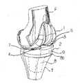
図1に、本発明に係る人工膝関節を膝関節部位に設置した状態を示す。前記人工膝関節は、大腿骨Fの遠位部に固定される大腿骨コンポーネント1と、脛骨Tの近位部に固定される脛骨コンポーネント2とから構成される。このうち脛骨コンポーネント2は、脛骨内に埋入されるステム8aとトレー8bとが一体的に形成されているトレー部材8と、大腿骨コンポーネントが摺動する摺動部材9とから構成される。
【0019】
図2は、前記大腿骨コンポーネント1の前面図である。この大腿骨コンポーネント1には外顆と内顆にそれぞれ外顆摺動面7と内顆摺動面6が形成され、これらが、後述の脛骨コンポーネント2の外側摺動面4と内側摺動面3と摺動して関節面を構成する。
【0020】
ここで、前後、内外とは、解剖学的な方向、すなわち、コンポーネントが膝関節位置に設置されたときの、解剖学的な方向を指すものである。
【0021】
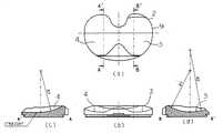
図3の(a)(b)には、本発明に係る人工膝関節を構成する脛骨コンポーネント2における摺動部材9の、上面図と前面図であり、図3の(c)(d)には、図3(a)のA−A’線断面図、B−B’線断面図を示す。
【0022】
脛骨コンポーネント2の大腿骨コンポーネント1の荷重を受ける内側摺動面3と外側摺動面4のうち、前記内側摺動面3は、前後方向断面で前方側が曲率半径R1の円弧をなすとともに後方側が曲率半径R2の円弧をなし[図3(d)参照]、他方の外側摺動面4は、前後方向断面で前方側がR1の円弧をなすとともに後方側が直線状であり、さらにR1<R2である[図3(c)参照]。
【0023】
このような大腿骨コンポーネント1と脛骨コンポーネントのトレー部材2はアルミナ、ジルコニアなどのセラミックスやステンレス鋼、コバルト・クロム合金、純チタン、チタン合金などの金属、高分子ポリエチレンなどの高分子材料などで形成することができる。また、脛骨コンポーネント2の摺動部材9は、前記大腿骨コンポーネント1と摺動できるようにするために高密度ポリエチレンなどの合成樹脂で形成されている。
【0024】
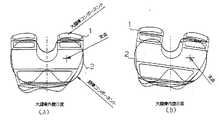
図4は、屈曲時における、脛骨コンポーネント2に対する大腿骨コンポーネント1の動きを示す説明図である。図4中、右側が内側で、左側が外側である。同図に示すように、膝の屈曲時には、外旋運動も発生する。
【0025】
このとき、図3に示すように、内側摺動面3の前側、後側にR曲面が設けられ、大腿骨コンポーネント2における内顆の摺動を抑制気味にしている。他方、外側摺動面4の後側を前後方向に直線状としたことから、大腿骨コンポーネント1の外顆の摺動に対する抑制を小さくしている。したがって、図4に示すように、大腿骨コンポーネント1は、内顆を支点としつつ外旋を行い、かつ、その際に、大腿骨コンポーネント1の外顆摺動面7と脛骨コンポーネント2の外側摺動面4との間の抵抗(摩擦力)を小さくして、動きがスムーズに滑らかに行なえるようになっている。
【0026】
したがって、生体にて作用する内顆を支点とした大腿骨外旋作用が自然に行える。
【0027】
また、大腿骨コンポーネント1の内顆を完全に拘束しないことから、屈曲時に摺動面に作用する抗力(接触応力)を小さくして、脛骨コンポーネント2の摺動面の異常摩耗や破損を防ぐことができる。
【0028】
また、通常の(屈曲を伴わない)回旋運動時にも、大腿骨コンポーネント2の浮き上がりを防止して、人工膝関節周囲の靱帯に過度な緊張を生じさせることなく大きな屈曲角度を得ることができる。さらに、大腿骨コンポーネント1の内顆を完全に拘束しないため、人工膝関節置換術の結果、生体的にバランスが崩れた状態で、大腿骨コンポーネント1や脛骨コンポーネント2が埋入された場合でも、人工膝関節周囲の靱帯に過度な緊張を生じさせることなく大きな屈曲角度を得ることができる。
【0029】
さらに、脛骨コンポーネント2の外後ろ側の摺動面を前後方向に直線状とし、大腿骨コンポーネント1の内顆の後方へのロールバックを許容していることから、外顆を中心とした回旋運動でも、屈曲時に摺動面に作用する抗力(接触応力)を小さくして、脛骨コンポーネント2の摺動面の異常摩耗や破損を防ぐとともに、回旋運動時の大腿骨コンポーネント1の浮き上がりを防止して、人工膝関節周囲の靱帯に過度な緊張を生じさせることなく大きな屈曲角度を得ることができる。
【0030】
次に、図5に、別の実施形態を示す。同図に示すように、脛骨コンポーネント2における摺動部材に設けた内側摺動面3は、前側のR曲面(R1の円弧)と後側のR曲面(R2の円弧)との間の中間部5に、前後方向に直線状の直線状面を備えている点で、図3に示す実施形態と異なっている。
【0031】
かかる構成によれば、過度の外反変形膝において、外側側副靱帯に過度の緊張が生じた場合、若干の外顆支持運動を許容することで、靱帯の緊張を緩和し、屈曲角度の増大が可能となる。
【0032】
また、前記脛骨コンポーネント2の外側摺動面4を、前記前後方向に対して直交する方向(図2参照)で円弧状にするとともに、その円弧の曲率半径を前側から後側に向かって漸増させることが好ましい。
【0033】
このような構成とすることで、脛骨コンポーネント2の内後方側における横方向の動きの自由度が高まることから、屈曲時に、屈曲時に摺動面に作用する抗力(接触応力)を小さくする作用が強くなる。
【0034】
以下、本発明の実施形態を例示したが、本発明は前述の実施形態に限定されるものではなく、発明の目的を逸脱しない限り任意の形態とすることができる。
【0035】
【発明の効果】
以上のように本発明の人工膝関節によれば、大腿骨の遠位部に固定される大腿骨コンポーネントと、脛骨の近位部に固定される脛骨コンポーネントとから構成され、該脛骨コンポーネントに前記大腿骨コンポーネントの荷重を受ける内側摺動面及び外側摺動面を有する人工膝関節において、前記内側摺動面は、前後方向断面で前側と後側がともに円弧状をなし、前記外側摺動面は、前後方向断面で前側が円弧状をなすとともに後側が直線状であることから、生体にて作用する内顆を支点とした大腿骨外旋作用が自然に行え、また、大腿骨コンポーネントの内顆を完全に拘束しないことから、屈曲時に摺動面に作用する抗力(接触応力)を小さくして、脛骨コンポーネントの摺動面の異常摩耗や破損を防ぐことができる。また、回旋運動時の大腿骨コンポーネントの浮き上がりを防止して、人工膝関節周囲の靱帯に過度な緊張を生じさせることなく大きな屈曲角度を得ることができる。さらに、大腿骨コンポーネントの内顆を完全に拘束しないため、人工膝関節置換術の結果、生体的にバランスが崩れた状態で、大腿骨コンポーネントや脛骨コンポーネントが埋入された場合でも、人工膝関節周囲の靱帯に過度な緊張を生じさせることなく大きな屈曲角度を得ることができる。また、脛骨コンポーネントの外後ろ側の摺動面を前後方向に直線状とし、大腿骨コンポーネントの内顆の後方へのロールバックを許容していることから、外顆を中心とした回旋運動でも、屈曲時に摺動面に作用する抗力(接触応力)を小さくして、脛骨コンポーネントの摺動面の異常摩耗や破損を防ぐとともに、回旋運動時の大腿骨コンポーネントの浮き上がりを防止して、人工膝関節周囲の靱帯に過度な緊張を生じさせることなく大きな屈曲角度を得ることができる。
【0036】
また、前記脛骨コンポーネントの内側摺動面を、前後方向断面で中間部が直線状であるようにすることで、過度の外反変形膝において、外側側副靱帯に過度の緊張が生じた場合、若干の外顆支持運動を許容することで、靱帯の緊張を緩和し、屈曲角度の増大が可能となる。
【0037】
また、前記脛骨コンポーネントの外側摺動面を、前記前後方向に直交する方向で円弧状にするとともに、その円弧の曲率半径が前側から後側に向かって漸増させた場合、脛骨コンポーネントの内後方側における横方向の動きの自由度が高まることから、屈曲時に、屈曲時に摺動面に作用する抗力(接触応力)を小さくする作用が強くなる。
【図面の簡単な説明】
【図1】本発明に係る人工膝関節を膝関節部位に設置した状態を示す斜視図である。
【図2】図1の人工膝関節を構成する大腿骨コンポーネントの前面図である。
【図3】(a)(b)は、図1の人工膝関節を構成する脛骨コンポーネントにおける摺動部材の上面図と前面図であり、(c)(d)は、それぞれ(a)のA−A’線断面図、B−B’線断面図である。
【図4】(a)(b)は、図4は、屈曲時における、脛骨コンポーネントに対する大腿骨コンポーネントの動きを示す説明図である。
【図5】(a)(b)は、本発明の別の実施形態を示す、脛骨コンポーネントにおける摺動部材の上面図と前面図であり、(c)(d)は、それぞれ(a)のC−C’線断面図、D−D’線断面図である。
【図6】(a)(b)は、従来の人工膝関節を構成する脛骨コンポーネントにおける摺動部材の上面図と前面図であり、(c)は、(a)のE−E’線断面図ある。
【図7】(a)(b)は、従来の別の人工膝関節を構成する脛骨コンポーネントにおける摺動部材の上面図と前面図であり、(c)(d)はそれぞれ(a)のH−H’線断面図、J−J’線断面図ある。
【符号の説明】
F・・大腿骨
T・・脛骨
1・・大腿骨コンポーネント
2・・脛骨コンポーネント
3・・内側摺動面
4・・外側摺動面
5・・中間部
6・・内顆摺動面
7・・外顆摺動面
8・・トレー部材
8a・ステム
8b・トレー
9・・摺動部材
R・・曲率半径[0001]
TECHNICAL FIELD OF THE INVENTION
The present invention relates to an artificial knee joint used to restore a highly deformed knee joint such as rheumatoid arthritis, knee osteoarthritis, pseudogout, and sudden osteonecrosis to normal function.
[0002]
[Prior art]
As shown in FIG. 6, in the conventional artificial knee joint, the inner sliding
[0003]
As another conventional knee prosthesis, as shown in FIG. 7, there is one in which an asymmetric inner
[0004]
In this artificial knee joint, the inner sliding
[0005]
[Patent Document 1]
US Patent No. 6013103 Specification
[Problems to be solved by the invention]
However, in the conventional knee prosthesis shown in FIG. 6, although the R curved surface provided before and after the sliding surface of the tibial component provides stability of the femoral component in the longitudinal direction when the knee joint is extended, In addition, due to the rotating motion generated between the femoral component and the tibial component at the time of bending, a large drag (contact stress) is generated on the sliding surface, which may cause abnormal wear or breakage of the sliding surface of the tibial component.
[0007]
In addition, the rotation of the femur may cause the femoral component to lift up along the curved surface of the tibial component, causing excessive tension on the surrounding ligaments and soft tissues, which may result in a reduced flexion angle.
[0008]
In addition, in the conventional artificial knee joint shown in FIG. 7, since the internal condyle of the femoral component is completely restrained, the rotational axis of the artificial knee joint becomes unbalanced due to imbalance in the ligament balance of the living body and inadequate knee replacement. If the rotation axis does not coincide with the ideal rotation axis on the living body, the drag (contact stress) acting on the sliding surface at the time of bending becomes extremely large, which may cause abnormal wear and breakage of the sliding surface of the tibial component, Preventing the femoral component from lifting during the rotation motion may cause excessive tension in the ligament around the knee prosthesis, which may reduce the flexion angle.
[0009]
The present invention has been made in view of the above-mentioned problems of the related art, and reduces a reaction force (contact stress) acting on a sliding surface at the time of bending to prevent abnormal wear and breakage of a sliding surface of a tibial component and a thigh during a rotation motion. An object of the present invention is to prevent a bone component from rising and prevent a bending angle from being reduced.
[0010]
[Means for Solving the Problems]
In order to solve the above problem, the artificial knee joint according to
[0011]
The artificial knee joint according to
[0012]
4. The artificial knee joint according to
[0013]
According to the configuration of
[0014]
In addition, since the sliding surface on the outer posterior side of the tibial component is linear in the anterior-posterior direction and the posterior rollback of the inner condyle of the femoral component is allowed, even in the rotation motion around the outer condyle, By reducing the drag (contact stress) acting on the sliding surface during flexion, it prevents abnormal wear and breakage of the sliding surface of the tibial component, and also prevents the rise of the femoral component during the rotation motion, thereby making the artificial knee joint prosthetic. Large bend angles can be obtained without causing excessive strain on the surrounding ligaments.
[0015]
According to the second aspect of the present invention, in the case of excessive varus deformity knee, if excessive tension occurs in the lateral collateral ligament, a slight movement of the lateral condyles is allowed to relax the tension of the ligament. , The bending angle can be increased.
[0016]
Next, according to the configuration of
[0017]
BEST MODE FOR CARRYING OUT THE INVENTION
Hereinafter, embodiments of the present invention will be described with reference to the drawings.
[0018]
FIG. 1 shows a state where an artificial knee joint according to the present invention is installed at a knee joint site. The knee prosthesis includes a
[0019]
FIG. 2 is a front view of the
[0020]
Here, front and rear, inside and outside refer to the anatomical direction, that is, the anatomical direction when the component is installed at the position of the knee joint.
[0021]
FIGS. 3A and 3B are a top view and a front view of the sliding
[0022]
Of the inner sliding
[0023]
The
[0024]
FIG. 4 is an explanatory diagram showing the movement of the
[0025]
At this time, as shown in FIG. 3, R curved surfaces are provided on the front side and the rear side of the inner sliding
[0026]
Therefore, the external rotation of the femur with the inner condyle acting in the living body as a fulcrum can be performed naturally.
[0027]
In addition, since the inner condyle of the
[0028]
In addition, even during a normal (without flexion) rotation motion, the
[0029]
Further, since the sliding surface on the outer posterior side of the
[0030]
Next, FIG. 5 shows another embodiment. As shown in the figure, an inner sliding
[0031]
According to such a configuration, in the case of excessive varus deformity knee, when excessive tension occurs in the lateral collateral ligament, by slightly allowing the condylar support movement, the tension of the ligament is relaxed, and the bending angle is increased. Becomes possible.
[0032]
The outer sliding
[0033]
With such a configuration, the degree of freedom of the lateral movement on the medial and posterior side of the
[0034]
Hereinafter, embodiments of the present invention have been exemplified, but the present invention is not limited to the above-described embodiments, and may be in any form without departing from the object of the invention.
[0035]
【The invention's effect】
As described above, according to the artificial knee joint of the present invention, a femoral component fixed to the distal part of the femur, and a tibial component fixed to the proximal part of the tibia, the tibia component In an artificial knee joint having an inner sliding surface and an outer sliding surface that receive a load of a femoral component, the inner sliding surface has an arc shape on both front and rear sides in a front-rear cross section, and the outer sliding surface has In the anterior-posterior cross section, the anterior side is arcuate and the posterior side is straight, so that the external rotation of the femur can be naturally performed with the inner condyle acting in the living body as a fulcrum, and the inner condyle of the femoral component Is not completely restrained, the resistance (contact stress) acting on the sliding surface during bending can be reduced, and abnormal wear and breakage of the sliding surface of the tibial component can be prevented. Further, it is possible to prevent the femoral component from being lifted during the rotation motion, and to obtain a large bending angle without excessively tensioning the ligament around the artificial knee joint. Furthermore, since the internal condyle of the femoral component is not completely restrained, even if the femoral component or the tibial component is implanted in a biologically unbalanced state as a result of a total knee replacement, the total knee arthroplasty is performed. Large bend angles can be obtained without causing excessive strain on the surrounding ligaments. In addition, since the sliding surface on the outer posterior side of the tibial component is linear in the anterior-posterior direction and the posterior rollback of the inner condyle of the femoral component is allowed, even in the rotation motion around the outer condyle, By reducing the drag (contact stress) acting on the sliding surface during flexion, it prevents abnormal wear and breakage of the sliding surface of the tibial component, and also prevents the rise of the femoral component during the rotation motion, thereby making the artificial knee joint prosthetic. Large bend angles can be obtained without causing excessive strain on the surrounding ligaments.
[0036]
Also, by making the medial sliding surface of the medial sliding surface of the tibial component straight in the anteroposterior cross-section, in the case of excessive varus deformity knee, if excessive tension occurs in the lateral collateral ligament, By allowing some lateral condylar support movement, the tension in the ligament can be reduced and the flexion angle can be increased.
[0037]
Further, the outer sliding surface of the tibial component is formed in an arc shape in a direction perpendicular to the front-rear direction, and when the radius of curvature of the arc is gradually increased from the front side to the rear side, the inner posterior side of the tibial component. Since the degree of freedom of the lateral movement in the direction is increased, the effect of reducing the drag (contact stress) acting on the sliding surface at the time of bending becomes stronger.
[Brief description of the drawings]
FIG. 1 is a perspective view showing a state where an artificial knee joint according to the present invention is installed at a knee joint site.
2 is a front view of a femoral component constituting the knee prosthesis of FIG. 1;
FIGS. 3 (a) and 3 (b) are a top view and a front view of a sliding member of a tibial component constituting the knee joint prosthesis of FIG. 1, and FIGS. 3 (c) and 3 (d) respectively show A of FIG. FIG. 3 is a cross-sectional view taken along a line A-A ′ and a line BB ′.
FIGS. 4A and 4B are explanatory diagrams showing movement of a femoral component with respect to a tibia component during bending.
FIGS. 5 (a) and 5 (b) are a top view and a front view of a sliding member in a tibial component, showing another embodiment of the present invention, and FIGS. It is CC 'line sectional drawing, DD' line sectional drawing.
6 (a) and 6 (b) are a top view and a front view of a sliding member in a tibial component constituting a conventional knee prosthesis, and FIG. 6 (c) is a cross section taken along line EE ′ of FIG. There is a figure.
FIGS. 7 (a) and 7 (b) are a top view and a front view of a sliding member of a tibial component constituting another conventional knee prosthesis, and FIGS. 7 (c) and (d) are H in FIG. 7 (a), respectively. FIG. 3 is a cross-sectional view taken along line -H ′ and a line JJ ′.
[Explanation of symbols]
F ・ Femur T ・ ・
Claims (3)
Translated fromJapanesePriority Applications (2)
| Application Number | Priority Date | Filing Date | Title |
|---|---|---|---|
| JP2003047009AJP4045194B2 (en) | 2003-02-25 | 2003-02-25 | Artificial knee joint |
| US10/787,062US7309362B2 (en) | 2003-02-25 | 2004-02-25 | Artificial knee joint |
Applications Claiming Priority (1)
| Application Number | Priority Date | Filing Date | Title |
|---|---|---|---|
| JP2003047009AJP4045194B2 (en) | 2003-02-25 | 2003-02-25 | Artificial knee joint |
Publications (2)
| Publication Number | Publication Date |
|---|---|
| JP2004254811Atrue JP2004254811A (en) | 2004-09-16 |
| JP4045194B2 JP4045194B2 (en) | 2008-02-13 |
Family
ID=32984348
Family Applications (1)
| Application Number | Title | Priority Date | Filing Date |
|---|---|---|---|
| JP2003047009AExpired - Fee RelatedJP4045194B2 (en) | 2003-02-25 | 2003-02-25 | Artificial knee joint |
Country Status (2)
| Country | Link |
|---|---|
| US (1) | US7309362B2 (en) |
| JP (1) | JP4045194B2 (en) |
Cited By (15)
| Publication number | Priority date | Publication date | Assignee | Title |
|---|---|---|---|---|
| JP2010172569A (en)* | 2009-01-30 | 2010-08-12 | Japan Medical Materials Corp | Artificial knee joint |
| JP2013501555A (en)* | 2009-08-10 | 2013-01-17 | ヴィース、ウルス | Knee prosthesis |
| JP2013536005A (en)* | 2010-07-24 | 2013-09-19 | ジンマー,インコーポレイティド | Asymmetric tibial components for knee prostheses |
| US9283082B2 (en) | 2010-07-24 | 2016-03-15 | Zimmer, Inc. | Methods related to seating of bearing component on tibial tray |
| US9308096B2 (en) | 2011-11-21 | 2016-04-12 | Zimmer, Inc. | Tibial baseplate with asymmetric placement of fixation structures |
| US9314343B2 (en) | 2010-09-10 | 2016-04-19 | Zimmer, Inc. | Motion facilitating tibial components for a knee prosthesis |
| US9381090B2 (en) | 2010-07-24 | 2016-07-05 | Zimmer, Inc. | Asymmetric tibial components for a knee prosthesis |
| US10188530B2 (en) | 2010-12-17 | 2019-01-29 | Zimmer, Inc. | Provisional tibial prosthesis system |
| US10278827B2 (en) | 2015-09-21 | 2019-05-07 | Zimmer, Inc. | Prosthesis system including tibial bearing component |
| US10675153B2 (en) | 2017-03-10 | 2020-06-09 | Zimmer, Inc. | Tibial prosthesis with tibial bearing component securing feature |
| US10835380B2 (en) | 2018-04-30 | 2020-11-17 | Zimmer, Inc. | Posterior stabilized prosthesis system |
| US10898337B2 (en) | 2011-11-18 | 2021-01-26 | Zimmer, Inc. | Tibial bearing component for a knee prosthesis with improved articular characteristics |
| US11324598B2 (en) | 2013-08-30 | 2022-05-10 | Zimmer, Inc. | Method for optimizing implant designs |
| US11324599B2 (en) | 2017-05-12 | 2022-05-10 | Zimmer, Inc. | Femoral prostheses with upsizing and downsizing capabilities |
| US11426282B2 (en) | 2017-11-16 | 2022-08-30 | Zimmer, Inc. | Implants for adding joint inclination to a knee arthroplasty |
Families Citing this family (35)
| Publication number | Priority date | Publication date | Assignee | Title |
|---|---|---|---|---|
| US20050033424A1 (en)* | 1999-05-10 | 2005-02-10 | Fell Barry M. | Surgically implantable knee prosthesis |
| US6520964B2 (en) | 2000-05-01 | 2003-02-18 | Std Manufacturing, Inc. | System and method for joint resurface repair |
| US6610067B2 (en) | 2000-05-01 | 2003-08-26 | Arthrosurface, Incorporated | System and method for joint resurface repair |
| ES2465090T3 (en) | 2002-12-20 | 2014-06-05 | Smith & Nephew, Inc. | High performance knee prostheses |
| US8388624B2 (en) | 2003-02-24 | 2013-03-05 | Arthrosurface Incorporated | Trochlear resurfacing system and method |
| US7465320B1 (en)* | 2004-05-06 | 2008-12-16 | Biomet Manufacturing Corp. | Knee joint prosthesis |
| WO2006004885A2 (en) | 2004-06-28 | 2006-01-12 | Arthrosurface, Inc. | System for articular surface replacement |
| DE102005009496B4 (en)* | 2005-03-02 | 2012-12-20 | Mathys Ag Bettlach | Knee joint endoprosthesis with intermediate element with differently designed sliding surfaces |
| US8211181B2 (en)* | 2005-12-14 | 2012-07-03 | New York University | Surface guided knee replacement |
| US8292964B2 (en)* | 2005-12-14 | 2012-10-23 | New York University | Surface guided knee replacement |
| CA2641966C (en)* | 2005-12-15 | 2016-11-22 | Zimmer, Inc. | Distal femoral knee prostheses |
| US9358029B2 (en) | 2006-12-11 | 2016-06-07 | Arthrosurface Incorporated | Retrograde resection apparatus and method |
| US8292965B2 (en)* | 2008-02-11 | 2012-10-23 | New York University | Knee joint with a ramp |
| US8298288B2 (en)* | 2008-06-24 | 2012-10-30 | New York University | Recess-ramp knee joint prosthesis |
| JP2010075697A (en)* | 2008-09-22 | 2010-04-08 | Buechel-Pappas Trust | Fixed bearing joint endoprosthesis with combined congruent-incongruent prosthetic articulation surface |
| WO2010085656A1 (en) | 2009-01-23 | 2010-07-29 | Zimmer, Inc. | Posterior stabilized total knee prosthesis |
| WO2010121250A1 (en) | 2009-04-17 | 2010-10-21 | Arthrosurface Incorporated | Glenoid resurfacing system and method |
| AU2010236182A1 (en) | 2009-04-17 | 2011-11-24 | Arthrosurface Incorporated | Glenoid resurfacing system and method |
| US10945743B2 (en) | 2009-04-17 | 2021-03-16 | Arthrosurface Incorporated | Glenoid repair system and methods of use thereof |
| EP2542165A4 (en) | 2010-03-05 | 2015-10-07 | Arthrosurface Inc | Tibial resurfacing system and method |
| US9132014B2 (en)* | 2010-04-13 | 2015-09-15 | Zimmer, Inc. | Anterior cruciate ligament substituting knee implants |
| CN103327937B (en)* | 2011-01-27 | 2017-08-08 | 史密夫和内修有限公司 | constrained knee prosthesis |
| US9066716B2 (en) | 2011-03-30 | 2015-06-30 | Arthrosurface Incorporated | Suture coil and suture sheath for tissue repair |
| WO2013007747A1 (en) | 2011-07-13 | 2013-01-17 | Zimmer Gmbh | Femoral knee prosthesis with diverging lateral condyle |
| EP2804565B1 (en) | 2011-12-22 | 2018-03-07 | Arthrosurface Incorporated | System for bone fixation |
| WO2014008126A1 (en) | 2012-07-03 | 2014-01-09 | Arthrosurface Incorporated | System and method for joint resurfacing and repair |
| US9492200B2 (en) | 2013-04-16 | 2016-11-15 | Arthrosurface Incorporated | Suture system and method |
| US9931219B2 (en) | 2014-03-07 | 2018-04-03 | Arthrosurface Incorporated | Implant and anchor assembly |
| US10624748B2 (en) | 2014-03-07 | 2020-04-21 | Arthrosurface Incorporated | System and method for repairing articular surfaces |
| US11607319B2 (en) | 2014-03-07 | 2023-03-21 | Arthrosurface Incorporated | System and method for repairing articular surfaces |
| US10413414B2 (en)* | 2015-07-08 | 2019-09-17 | New York University | Replica guided motion knee |
| US11160663B2 (en) | 2017-08-04 | 2021-11-02 | Arthrosurface Incorporated | Multicomponent articular surface implant |
| EP3698761B1 (en) | 2019-02-22 | 2021-11-17 | Stryker European Operations Limited | Total ankle prosthesis |
| WO2020186099A1 (en) | 2019-03-12 | 2020-09-17 | Arthrosurface Incorporated | Humeral and glenoid articular surface implant systems and methods |
| EP3954335B1 (en)* | 2019-04-11 | 2023-12-13 | Teijin Nakashima Medical Co., Ltd. | Artificial knee joint |
Citations (17)
| Publication number | Priority date | Publication date | Assignee | Title |
|---|---|---|---|---|
| US4224696A (en)* | 1978-09-08 | 1980-09-30 | Hexcel Corporation | Prosthetic knee |
| US4301553A (en)* | 1975-08-15 | 1981-11-24 | United States Surgical Corporation | Prosthetic knee joint |
| EP0346183A1 (en)* | 1988-05-31 | 1989-12-13 | Societe Civile D'etude Et De Recherche De Nouvelles Protheses (Scernp) | Sliding knee prothesis |
| JPH03502291A (en)* | 1988-02-02 | 1991-05-30 | ジョイント・メディカル・プロダクツ・コーポレーション | artificial joint |
| EP0447065A2 (en)* | 1990-03-12 | 1991-09-18 | Howmedica International Inc. | Tibial component for a replacement knee prosthesis and total knee prosthesis incorporating such a component |
| US5071438A (en)* | 1990-11-07 | 1991-12-10 | Intermedics Orthopedics, Inc. | Tibial prothesis with pivoting articulating surface |
| US5219362A (en)* | 1991-02-07 | 1993-06-15 | Finsbury (Instruments) Limited | Knee prosthesis |
| JPH07503147A (en)* | 1991-09-16 | 1995-04-06 | ハーバー―ユーシーエルエーリサーチ アンド エデュケーション インスティテュート インコーポレイテッド | Total knee prosthesis with fixed axis of rotation |
| JPH07144005A (en)* | 1993-07-16 | 1995-06-06 | Peter Stanley Walker | Knee prosthesis |
| JPH07144006A (en)* | 1993-07-16 | 1995-06-06 | Peter Stanley Walker | Prosthesis for replacing knee |
| WO1995025484A1 (en)* | 1994-03-24 | 1995-09-28 | Corin Medical Limited | Prosthesis assembly |
| JPH11502433A (en)* | 1995-02-03 | 1999-03-02 | クライプティッチ プロプライエタリー リミテッド | Knee prosthesis |
| JP2000116682A (en)* | 1998-10-13 | 2000-04-25 | Michael J Pappas | Femur member for prosthesis to be incorporated in knee |
| JP2000514338A (en)* | 1996-07-11 | 2000-10-31 | ライト メディカル テクノロジー インコーポレーテッド | Knee prosthesis |
| WO2001006961A1 (en)* | 1999-07-26 | 2001-02-01 | Michel Bercovy | Novel knee prosthesis |
| JP2002011026A (en)* | 2000-05-29 | 2002-01-15 | Sulzer Orthopedics Ltd | Prosthetic device for knees |
| US20040243244A1 (en)* | 2002-12-20 | 2004-12-02 | Jason Otto | High performance knee prostheses |
Family Cites Families (6)
| Publication number | Priority date | Publication date | Assignee | Title |
|---|---|---|---|---|
| USRE29757E (en)* | 1971-04-21 | 1978-09-12 | Replacements for bicondylar joints in human limbs | |
| CH686611A5 (en)* | 1992-01-14 | 1996-05-15 | Sulzer Medizinaltechnik Ag | Art Royal knee. |
| US5330534A (en)* | 1992-02-10 | 1994-07-19 | Biomet, Inc. | Knee joint prosthesis with interchangeable components |
| ES2208848T3 (en)* | 1997-07-10 | 2004-06-16 | Societe Ortho-Id | KNEE ARTICULATION PROTESIS. |
| JP3679315B2 (en)* | 2000-07-19 | 2005-08-03 | 経憲 武井 | Knee prosthesis |
| AU2002365379A1 (en)* | 2001-11-28 | 2003-06-10 | Wright Medical Technology, Inc. | Knee joint prostheses |
- 2003
- 2003-02-25JPJP2003047009Apatent/JP4045194B2/ennot_activeExpired - Fee Related
- 2004
- 2004-02-25USUS10/787,062patent/US7309362B2/ennot_activeExpired - Lifetime
Patent Citations (18)
| Publication number | Priority date | Publication date | Assignee | Title |
|---|---|---|---|---|
| US4301553A (en)* | 1975-08-15 | 1981-11-24 | United States Surgical Corporation | Prosthetic knee joint |
| US4224696A (en)* | 1978-09-08 | 1980-09-30 | Hexcel Corporation | Prosthetic knee |
| JPH03502291A (en)* | 1988-02-02 | 1991-05-30 | ジョイント・メディカル・プロダクツ・コーポレーション | artificial joint |
| EP0346183A1 (en)* | 1988-05-31 | 1989-12-13 | Societe Civile D'etude Et De Recherche De Nouvelles Protheses (Scernp) | Sliding knee prothesis |
| EP0447065A2 (en)* | 1990-03-12 | 1991-09-18 | Howmedica International Inc. | Tibial component for a replacement knee prosthesis and total knee prosthesis incorporating such a component |
| US5071438A (en)* | 1990-11-07 | 1991-12-10 | Intermedics Orthopedics, Inc. | Tibial prothesis with pivoting articulating surface |
| US5219362A (en)* | 1991-02-07 | 1993-06-15 | Finsbury (Instruments) Limited | Knee prosthesis |
| JPH07503147A (en)* | 1991-09-16 | 1995-04-06 | ハーバー―ユーシーエルエーリサーチ アンド エデュケーション インスティテュート インコーポレイテッド | Total knee prosthesis with fixed axis of rotation |
| JPH07144005A (en)* | 1993-07-16 | 1995-06-06 | Peter Stanley Walker | Knee prosthesis |
| JPH07144006A (en)* | 1993-07-16 | 1995-06-06 | Peter Stanley Walker | Prosthesis for replacing knee |
| WO1995025484A1 (en)* | 1994-03-24 | 1995-09-28 | Corin Medical Limited | Prosthesis assembly |
| JPH11502433A (en)* | 1995-02-03 | 1999-03-02 | クライプティッチ プロプライエタリー リミテッド | Knee prosthesis |
| JP2000514338A (en)* | 1996-07-11 | 2000-10-31 | ライト メディカル テクノロジー インコーポレーテッド | Knee prosthesis |
| JP2000116682A (en)* | 1998-10-13 | 2000-04-25 | Michael J Pappas | Femur member for prosthesis to be incorporated in knee |
| WO2001006961A1 (en)* | 1999-07-26 | 2001-02-01 | Michel Bercovy | Novel knee prosthesis |
| JP2003505148A (en)* | 1999-07-26 | 2003-02-12 | ミシェル、ベルコビ | New knee prosthesis |
| JP2002011026A (en)* | 2000-05-29 | 2002-01-15 | Sulzer Orthopedics Ltd | Prosthetic device for knees |
| US20040243244A1 (en)* | 2002-12-20 | 2004-12-02 | Jason Otto | High performance knee prostheses |
Cited By (36)
| Publication number | Priority date | Publication date | Assignee | Title |
|---|---|---|---|---|
| JP2010172569A (en)* | 2009-01-30 | 2010-08-12 | Japan Medical Materials Corp | Artificial knee joint |
| JP2013501555A (en)* | 2009-08-10 | 2013-01-17 | ヴィース、ウルス | Knee prosthesis |
| US11224519B2 (en) | 2010-07-24 | 2022-01-18 | Zimmer, Inc. | Asymmetric tibial components for a knee prosthesis |
| US10195041B2 (en) | 2010-07-24 | 2019-02-05 | Zimmer, Inc. | Asymmetric tibial components for a knee prosthesis |
| JP2015231566A (en)* | 2010-07-24 | 2015-12-24 | ジンマー,インコーポレイティド | Asymmetric tibial components for knee prostheses |
| US9283082B2 (en) | 2010-07-24 | 2016-03-15 | Zimmer, Inc. | Methods related to seating of bearing component on tibial tray |
| US9295557B2 (en) | 2010-07-24 | 2016-03-29 | Zimmer, Inc. | Asymmetric tibial components for a knee prosthesis |
| US12239540B2 (en) | 2010-07-24 | 2025-03-04 | Zimmer, Inc. | Asymmetric tibial components for a knee prosthesis |
| JP2013536005A (en)* | 2010-07-24 | 2013-09-19 | ジンマー,インコーポレイティド | Asymmetric tibial components for knee prostheses |
| US9381090B2 (en) | 2010-07-24 | 2016-07-05 | Zimmer, Inc. | Asymmetric tibial components for a knee prosthesis |
| US10543099B2 (en) | 2010-07-24 | 2020-01-28 | Zimmer, Inc. | Tibial prosthesis |
| US10470889B2 (en) | 2010-07-24 | 2019-11-12 | Zimmer, Inc. | Asymmetric tibial components for a knee prosthesis |
| US9763794B2 (en) | 2010-07-24 | 2017-09-19 | Zimmer, Inc. | Tibial prosthesis |
| US9763796B2 (en) | 2010-07-24 | 2017-09-19 | Zimmer, Inc. | Asymmetric tibial components for a knee prosthesis |
| US9861490B2 (en) | 2010-07-24 | 2018-01-09 | Zimmer, Inc. | Asymmetric tibial components for a knee prosthesis |
| US9918844B2 (en) | 2010-07-24 | 2018-03-20 | Zimmer, Inc. | Tibial prosthesis with a fixed bearing component |
| US9192480B2 (en) | 2010-07-24 | 2015-11-24 | Zimmer, Inc. | Asymmetric tibial components for a knee prosthesis |
| US9763795B2 (en) | 2010-09-10 | 2017-09-19 | Zimmer, Inc. | Motion facilitating tibial components for a knee prosthesis |
| US10413415B2 (en) | 2010-09-10 | 2019-09-17 | Zimmer, Inc. | Motion facilitating tibial components for a knee prosthesis |
| US11471288B2 (en) | 2010-09-10 | 2022-10-18 | Zimmer, Inc. | Motion facilitating tibial components for a knee prosthesis |
| US9314343B2 (en) | 2010-09-10 | 2016-04-19 | Zimmer, Inc. | Motion facilitating tibial components for a knee prosthesis |
| US10188530B2 (en) | 2010-12-17 | 2019-01-29 | Zimmer, Inc. | Provisional tibial prosthesis system |
| US12383407B2 (en) | 2011-11-18 | 2025-08-12 | Zimmer, Inc. | Tibial bearing component for a knee prosthesis with improved articular characteristics |
| US10898337B2 (en) | 2011-11-18 | 2021-01-26 | Zimmer, Inc. | Tibial bearing component for a knee prosthesis with improved articular characteristics |
| US10265181B2 (en) | 2011-11-21 | 2019-04-23 | Zimmer, Inc. | Tibial baseplate with asymmetric placement of fixation structures |
| US9707089B2 (en) | 2011-11-21 | 2017-07-18 | Zimmer, Inc. | Tibial baseplate with asymmetric placement of fixation structures |
| US9308096B2 (en) | 2011-11-21 | 2016-04-12 | Zimmer, Inc. | Tibial baseplate with asymmetric placement of fixation structures |
| US11324598B2 (en) | 2013-08-30 | 2022-05-10 | Zimmer, Inc. | Method for optimizing implant designs |
| US11160659B2 (en) | 2015-09-21 | 2021-11-02 | Zimmer, Inc. | Prosthesis system including tibial bearing component |
| US10278827B2 (en) | 2015-09-21 | 2019-05-07 | Zimmer, Inc. | Prosthesis system including tibial bearing component |
| US11547571B2 (en) | 2017-03-10 | 2023-01-10 | Zimmer, Inc. | Tibial prosthesis with tibial bearing component securing feature |
| US10675153B2 (en) | 2017-03-10 | 2020-06-09 | Zimmer, Inc. | Tibial prosthesis with tibial bearing component securing feature |
| US11324599B2 (en) | 2017-05-12 | 2022-05-10 | Zimmer, Inc. | Femoral prostheses with upsizing and downsizing capabilities |
| US11426282B2 (en) | 2017-11-16 | 2022-08-30 | Zimmer, Inc. | Implants for adding joint inclination to a knee arthroplasty |
| US10835380B2 (en) | 2018-04-30 | 2020-11-17 | Zimmer, Inc. | Posterior stabilized prosthesis system |
| US11911279B2 (en) | 2018-04-30 | 2024-02-27 | Zimmer, Inc. | Posterior stabilized prosthesis system |
Also Published As
| Publication number | Publication date |
|---|---|
| US20040186582A1 (en) | 2004-09-23 |
| US7309362B2 (en) | 2007-12-18 |
| JP4045194B2 (en) | 2008-02-13 |
Similar Documents
| Publication | Publication Date | Title |
|---|---|---|
| JP4045194B2 (en) | Artificial knee joint | |
| US20220280305A1 (en) | Orthopaedic femoral component having controlled condylar curvature | |
| US10729551B2 (en) | Orthopaedic knee prosthesis having controlled condylar curvature | |
| EP1591082B1 (en) | An artificial knee joint | |
| JP5410027B2 (en) | Movable support assembly | |
| JP4559061B2 (en) | Femoral component for knee prosthesis | |
| US12115080B2 (en) | Total knee implant prosthesis assembly and method | |
| EP2512380B1 (en) | Implant for restoring normal range of flexion and kinematics of the knee | |
| JP4887292B2 (en) | Artificial knee joint | |
| JP5535533B2 (en) | Posterior stable orthopedic prosthesis | |
| JP4820547B2 (en) | Self-aligning knee prosthesis | |
| JP6033860B2 (en) | Retrostable orthopedic prosthesis assembly | |
| JPH05200057A (en) | Artificial joint, especially artificial knee joint | |
| JP5844148B2 (en) | Knee prosthesis with patella components of common dimensions with various thicknesses and apex surface diameters |
Legal Events
| Date | Code | Title | Description |
|---|---|---|---|
| A621 | Written request for application examination | Free format text:JAPANESE INTERMEDIATE CODE: A621 Effective date:20050712 | |
| A131 | Notification of reasons for refusal | Free format text:JAPANESE INTERMEDIATE CODE: A131 Effective date:20070731 | |
| A521 | Request for written amendment filed | Free format text:JAPANESE INTERMEDIATE CODE: A523 Effective date:20070926 | |
| TRDD | Decision of grant or rejection written | ||
| A01 | Written decision to grant a patent or to grant a registration (utility model) | Free format text:JAPANESE INTERMEDIATE CODE: A01 Effective date:20071026 | |
| A61 | First payment of annual fees (during grant procedure) | Free format text:JAPANESE INTERMEDIATE CODE: A61 Effective date:20071119 | |
| R150 | Certificate of patent or registration of utility model | Ref document number:4045194 Country of ref document:JP Free format text:JAPANESE INTERMEDIATE CODE: R150 Free format text:JAPANESE INTERMEDIATE CODE: R150 | |
| FPAY | Renewal fee payment (event date is renewal date of database) | Free format text:PAYMENT UNTIL: 20101122 Year of fee payment:3 | |
| FPAY | Renewal fee payment (event date is renewal date of database) | Free format text:PAYMENT UNTIL: 20101122 Year of fee payment:3 | |
| FPAY | Renewal fee payment (event date is renewal date of database) | Free format text:PAYMENT UNTIL: 20111122 Year of fee payment:4 | |
| FPAY | Renewal fee payment (event date is renewal date of database) | Free format text:PAYMENT UNTIL: 20111122 Year of fee payment:4 | |
| FPAY | Renewal fee payment (event date is renewal date of database) | Free format text:PAYMENT UNTIL: 20121122 Year of fee payment:5 | |
| FPAY | Renewal fee payment (event date is renewal date of database) | Free format text:PAYMENT UNTIL: 20121122 Year of fee payment:5 | |
| FPAY | Renewal fee payment (event date is renewal date of database) | Free format text:PAYMENT UNTIL: 20131122 Year of fee payment:6 | |
| LAPS | Cancellation because of no payment of annual fees |