JP2004251900A - Measurement method by chemical sensor and chemical sensor type measuring device - Google Patents
Measurement method by chemical sensor and chemical sensor type measuring deviceDownload PDFInfo
- Publication number
- JP2004251900A JP2004251900AJP2004023637AJP2004023637AJP2004251900AJP 2004251900 AJP2004251900 AJP 2004251900AJP 2004023637 AJP2004023637 AJP 2004023637AJP 2004023637 AJP2004023637 AJP 2004023637AJP 2004251900 AJP2004251900 AJP 2004251900A
- Authority
- JP
- Japan
- Prior art keywords
- potential
- electrode
- chemical sensor
- measurement
- working electrode
- Prior art date
- Legal status (The legal status is an assumption and is not a legal conclusion. Google has not performed a legal analysis and makes no representation as to the accuracy of the status listed.)
- Granted
Links
Images


Landscapes
- Apparatus Associated With Microorganisms And Enzymes (AREA)
Abstract
Translated fromJapaneseDescription
Translated fromJapanese本発明は、化学センサによる測定方法、ならびに該測定方法に基づく、化学センサ型装置に関し、より具体的には、電流検出型化学センサによる測定方法ならびに該測定方法に基づく、電流検出型の化学センサ型装置に関する。特には、該電流検出型化学センサとして、酵素電極を利用する電流検出型化学センサによる測定方法に関する。 The present invention relates to a measurement method using a chemical sensor and a chemical sensor-type device based on the measurement method, and more specifically, a measurement method using a current detection type chemical sensor and a current detection type chemical sensor based on the measurement method. Molding device. In particular, the present invention relates to a measurement method using a current detection type chemical sensor using an enzyme electrode as the current detection type chemical sensor.
液体試料中に含有される特定の物質濃度を測定する方法として、電気化学的反応を利用して、該特定物質の酸化または還元に伴う電流を検出する手法、具体的には、電流検出型化学センサを利用する測定方法がある。その際、実際には、測定対象である特定物質に酵素を作用させ、かかる酵素反応によって定量的に生成される酵素反応産物について、電気化学的反応を利用して、該酵素反応産物の酸化または還元に伴う電流を検出することによって、測定対象である特定物質の濃度を間接的に測定する手法が利用されている。具体的には、作用極として、導電体電極上に、前記酵素反応に利用する酵素膜層を設ける酵素電極、例えば、白金やカーボンなどの導電体電極上に、酵素を固定化した固定化酵素膜層を形成した固定化酵素電極を利用し、参照極との間に、所定の電位を印加して、液体試料中に含有される特定物質から該酵素の作用で生成する反応産物を、該作用極と参照極との間に印加されている電位によって、電気化学的反応を利用して、反応産物量に応じた電流を発生させる。 As a method for measuring the concentration of a specific substance contained in a liquid sample, a method of detecting a current associated with oxidation or reduction of the specific substance using an electrochemical reaction, specifically, a current detection type chemical There is a measurement method using a sensor. At that time, actually, an enzyme is allowed to act on a specific substance to be measured, and the enzyme reaction product quantitatively generated by the enzyme reaction is oxidized or oxidized using an electrochemical reaction. A technique of indirectly measuring the concentration of a specific substance to be measured by detecting a current accompanying reduction is used. Specifically, an immobilized enzyme in which an enzyme is immobilized on a conductive electrode as a working electrode, on which an enzyme film layer used for the enzyme reaction is provided on a conductive electrode, for example, on a conductive electrode such as platinum or carbon. Utilizing the immobilized enzyme electrode on which the membrane layer is formed, a predetermined potential is applied between the reference electrode and the reference electrode, and a reaction product generated by the action of the enzyme from a specific substance contained in the liquid sample, A current corresponding to the amount of the reaction product is generated by utilizing an electrochemical reaction by the potential applied between the working electrode and the reference electrode.
この酵素電極を利用する化学センサは、液体試料中、通常、水溶液試料中に浸漬して使用され、酵素膜層中を該水溶液試料が浸漬・透過する際、酵素膜層の表面に、試料に混入している異物、不純物が吸着する現象、あるいは、酵素膜層下の酵素電極用導電体電極表面に、汚染や変質が起きる現象が生じることがある。酵素膜層の表面に、異物、不純物が吸着すると、測定対象である特定物質に対する酵素反応の効率を低下させる要因となり、特定物質濃度に対する測定される電流量の比率(センサ感度)が経時的に徐々に低下させる要因となる。一方、導電体電極表面に、汚染や変質が起こると、酵素反応の効率は維持されていても、酵素反応産物の測定を行う電気化学的反応の効率が影響を受けるため、結果的に特定物質濃度に対する測定される電流量の比率(センサ感度)を経時的に低下させる要因となる。 A chemical sensor using this enzyme electrode is used by being immersed in a liquid sample, usually in an aqueous solution sample, and when the aqueous solution sample is immersed and permeates through the enzyme membrane layer, the sample is placed on the surface of the enzyme membrane layer. A phenomenon in which contaminants and impurities are adsorbed, or a phenomenon in which contamination or alteration occurs on the surface of the conductor electrode for the enzyme electrode under the enzyme film layer may occur. When foreign substances or impurities are adsorbed on the surface of the enzyme film layer, it causes a decrease in the efficiency of the enzymatic reaction for the specific substance to be measured, and the ratio of the measured current amount to the specific substance concentration (sensor sensitivity) changes over time. This is a factor that gradually decreases. On the other hand, if contamination or alteration occurs on the surface of the conductor electrode, the efficiency of the electrochemical reaction that measures the enzyme reaction product is affected even if the efficiency of the enzyme reaction is maintained, and as a result, specific substances This is a factor that decreases the ratio of the measured current amount to the concentration (sensor sensitivity) over time.
前述する酵素電極を利用する電流検出型化学センサを使用する際に生じる、例えば、作用極に用いる導電体電極表面の汚染や変質によって誘起されるセンサ感度低下を回復する手法として、幾つかの方法が提案されている。その一つは、酵素電極を利用する電流検出型化学センサを利用する際、測定時に通常、該作用極と対極との間に印加されている電位に対して、それと逆方向の電位を、一定の使用期間毎に、短時間、作用極と対極との間に印加することで、電極表面の汚染や変質を除去し、酵素電極の再活性化を果す方法が、特開昭57−060255号公報、特開昭60−155959号公報、特開平1−15649号公報などに提案されている。 There are several methods for recovering the sensor sensitivity decrease caused by the contamination or deterioration of the surface of the conductive electrode used for the working electrode, for example, which occurs when the current detection type chemical sensor using the enzyme electrode described above is used. Has been proposed. One of them is that when using a current detection type chemical sensor using an enzyme electrode, the potential in the opposite direction to the potential applied between the working electrode and the counter electrode during measurement is usually fixed. JP-A-57-060255 discloses a method for removing contamination and alteration on the electrode surface and reactivating the enzyme electrode by applying a voltage between the working electrode and the counter electrode for a short period of time for each use period. And Japanese Patent Application Laid-Open Nos. 60-155959 and 1-15649.
但し、この逆方向の電位を、一定の使用期間毎に、短時間、作用極と対極との間に印加する手法では、印加される逆方向の電位の大きさによっては、該化学センサを保管している緩衝水溶液において、電気化学的に水素発生を生じさせ、酵素電極において、作用極に用いる導電体電極表面に発生する微細な水素気泡が付着する状態を引き起こす場合もある。あるいは、電極に過電流が流れる場合もあり、その際、作用極に用いる導電体電極表面に過電流による損傷が発生する場合もある。 However, in a method in which the reverse potential is applied between the working electrode and the counter electrode for a short period of time at a fixed use period, the chemical sensor is stored depending on the magnitude of the applied reverse potential. Hydrogen may be electrochemically generated in the buffered aqueous solution, and fine hydrogen bubbles generated on the surface of the conductive electrode used as the working electrode may adhere to the enzyme electrode. Alternatively, an overcurrent may flow through the electrode, and at that time, the surface of the conductive electrode used for the working electrode may be damaged by the overcurrent.
反復測定に伴って生じる、上述する化学センサにおける感度低下を回復する手法として、短時間の逆方向電位を印加する方法における、種々の欠点を改善した方法も、特公平4−54175号公報に提案されている。該公報に開示される方法では、酵素電極を利用する電流検出型化学センサに対して、その測定後に、作用極(酵素電極)と対極との間に印加される電位について、三角波電位走査を行うことによって、酵素電極の再活性化を図り、センサ感度の経時的低下の改善を達成している。 As a method of restoring the above-described decrease in sensitivity of a chemical sensor caused by repeated measurement, a method of improving various disadvantages in a method of applying a short-time reverse potential is also proposed in Japanese Patent Publication No. 4-54175. Have been. In the method disclosed in the publication, a triangular potential scan is performed on a current detection type chemical sensor using an enzyme electrode, after the measurement, for a potential applied between a working electrode (enzyme electrode) and a counter electrode. As a result, the enzyme electrode is reactivated and improvement in the sensor sensitivity over time is achieved.
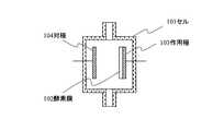
例えば、化学センサを用いた測定系を、図8に示すように、流入口と流出口を有するセル101の中に、表面に酵素膜102を固定化したPt線からなる酵素電極を利用する、作用極103と、Pt線からなる対極104とで構成する際、セル101中に、酵素反応の基質を含有していない緩衝液を満たした状態で、測定時に作用極103と対極104との間に印加される電位は、対極104を接地し、作用極103には、基準となる飽和カロメル電極(SCE)に対して、+0.6Vとなる電位が印加される。この印加電位において、セル101中に、一定流量で試料液を流入すると、試料液中に存在している特定物質(酵素基質物質)から、酵素膜102における酵素反応に伴って、酵素反応産物が生成し、該酵素反応産物が電気化学的反応を起こし、応答電流が流れる。緩衝液を流入している際に観測されるベース電流と、該応答電流との差は、酵素反応産物量に比例し、また、酵素反応を受ける特定物質(酵素基質物質)量に比例するので、予め作製されている検量線に基づき、試料液中に存在する特定物質(酵素基質物質)濃度の定量がなされる。測定後、セル101中に、緩衝液を流通して、洗浄する結果、酵素電極系は元の状態に戻る。この操作を繰り返すことで、反復して、異なる試料液についての測定を実施する。 For example, as shown in FIG. 8, a measurement system using a chemical sensor uses an enzyme electrode composed of a Pt line having an enzyme film 102 immobilized on a surface thereof in a cell 101 having an inlet and an outlet. When the working electrode 103 and the counter electrode 104 composed of a Pt line are formed, the cell 101 is filled with a buffer solution containing no substrate for the enzymatic reaction. , The counter electrode 104 is grounded, and the working electrode 103 is applied with a potential of +0.6 V with respect to the reference saturated calomel electrode (SCE). At this applied potential, when a sample liquid flows into the cell 101 at a constant flow rate, an enzyme reaction product is generated from a specific substance (enzyme substrate substance) present in the sample liquid with the enzyme reaction in the enzyme membrane 102. Then, the enzymatic reaction product causes an electrochemical reaction, and a response current flows. The difference between the base current observed during the flow of the buffer and the response current is proportional to the amount of the enzyme reaction product and proportional to the amount of the specific substance (enzyme substrate substance) that undergoes the enzyme reaction. The concentration of a specific substance (enzyme substrate substance) present in the sample solution is determined based on a previously prepared calibration curve. After the measurement, a buffer solution is circulated through the cell 101 to wash the cell, and as a result, the enzyme electrode system returns to the original state. By repeating this operation, measurement for different sample liquids is repeatedly performed.
この反復測定を進める際、試料液中に含まれる、測定対象の特定物質(酵素基質物質)以外の比較的高分子量を有する成分、例えば、蛋白質や脂質などが、酵素膜層の表面に僅かずつながら付着したり、また、比較的低分子量の成分、例えば、低分子のアミンや有機酸などは、酵素膜層の内部に浸入、透過して、導電体電極表面に吸着したり、あるいは、導電体電極表面に酸化物被膜の形成が生じたりする。特公平4−54175号公報に提案されている方法では、例えば、作用極と対極とが共に、白金極を用いる場合、利用する緩衝液において、水分子の電気分解や、緩衝液中の成分、支持電解質の酸化還元反応が生じない印加電位範囲、例えば、−0.5V〜+1.3V(SCEを基準とする印加電位)の範囲で、測定時の印加電位+0.6Vから、0.1〜1V/sの走査速度で、上限電位まで印加電位を増加させ、次いで、下限電位まで印加電位を減少させ、その後、該下限電位と上限電位との間で、三角波電位走査を一定時間継続する。最終的に、三角波電位走査を反復した後、当初の測定時の印加電位+0.6Vに達した時点で、三角波電位走査を終了する。前記の三角波電位走査による酵素電極の再活性化処理を、所定の測定回毎に実施することで、経時的に低下するセンサ感度の回復がなされ、長期に亘って、極端なセンサ感度の低下の無い状態を維持できている。 During this repetitive measurement, components having a relatively high molecular weight other than the specific substance (enzyme substrate substance) to be measured, such as proteins and lipids, contained in the sample solution are slightly added to the surface of the enzyme membrane layer. While adhering, relatively low molecular weight components, such as low molecular weight amines and organic acids, penetrate and permeate into the enzyme membrane layer and are adsorbed on the conductor electrode surface, or Or the formation of an oxide film on the surface of the body electrode. In the method proposed in Japanese Patent Publication No. 4-54175, for example, when the working electrode and the counter electrode both use a platinum electrode, the buffer solution to be used is used for electrolysis of water molecules, components in the buffer solution, In the range of applied potential at which the oxidation-reduction reaction of the supporting electrolyte does not occur, for example, in the range of -0.5 V to +1.3 V (applied potential based on SCE), the applied potential at the time of measurement is +0.6 V to 0.1 to 0.1 V. At a scanning speed of 1 V / s, the applied potential is increased to the upper limit potential, then the applied potential is reduced to the lower limit potential, and thereafter, the triangular wave potential scanning is continued between the lower limit potential and the upper limit potential for a certain period of time. Finally, after repeating the triangular wave potential scanning, the triangular wave potential scanning is terminated when the applied potential at the time of the initial measurement reaches +0.6 V. By performing the reactivation process of the enzyme electrode by the triangular wave potential scanning every predetermined measurement, the sensor sensitivity that decreases with time is recovered, and over a long period of time, the extreme decrease in sensor sensitivity is reduced. There is no state.
図9に例示するように、上限電位と下限電位の間で三角波電位走査を実施すると、正負の電位に印加された状態を交互に繰り返す間に、かかる電位の反転により、測定時に、電極表面に静電的に吸着される成分の除去がなされる。また、作用極103に用いる白金表面に形成される酸化物被覆膜も、正負の電位に印加された状態を交互に繰り返す間に、段階的に除去される。
上述する酵素電極の再活性化処理する方法は、反復測定に起因して経時的に低下するセンサ感度の回復には、有効な手段ではある。他方、利用される酵素電極を利用する電流検出型化学センサ自体は、一旦、作製過程で酵素電極上に形成した酵素膜層は乾燥した状態とされた上、使用開始の際、化学センサ全体は、緩衝液に浸漬され、酵素膜層の湿潤処理、作用極表面と参照極表面との間に緩衝液が満たされた状態とされる。また、作用極と参照極との間に、測定時に印加すべき所定の電位を印加する。 The method of reactivating the enzyme electrode described above is an effective means for recovering the sensor sensitivity, which decreases with time due to repeated measurement. On the other hand, in the current detection type chemical sensor itself using an enzyme electrode to be used, the enzyme film layer formed on the enzyme electrode in the manufacturing process is once in a dry state. The surface of the working electrode and the surface of the reference electrode are filled with the buffer solution. Further, a predetermined potential to be applied at the time of measurement is applied between the working electrode and the reference electrode.
本発明者は、前記の手順で使用開始時の化学センサのセッティング処理を行った場合、当初の応答電流は低く、かかる測定時の所定電位を印加して、1日〜数日間を経過する間に、応答電流の水準が徐々に上昇し、一定値の水準に達することを見出した。この使用開始直後に生じる、初期センサ感度の不安定性を解消し、所望のセンサ感度水準に簡便な操作で達成することが望ましく、従来認識されていない新たな課題である。さらには、かかる初期センサ感度の不安定性は、例えば、図1に示すように、絶縁性基板1上に、作用極2と参照極4を形成し、かかる両電極表面を被覆するように、液を含浸可能な接着層6を設け、かかる接着層6を介して、酵素膜層5を固定化する構成の酵素電極を利用する電流検出型化学センサにおいても、共通して見出されることが判明した。加えて、図5に示すように、接着層6と酵素膜層5との間に、酵素反応産物以外に作用極2表面で電気化学的反応を起こし、干渉成分となる低分子化合物の透過を抑制する機能を有する選択透過膜12を挿入し、さらに、酵素膜層5の表面に、かかる酵素反応にあずかる基質化合物の透過効率を制限する機能を有する制限透過膜11を設ける構成の酵素電極を利用する電流検出型化学センサにおいて、初期センサ感度の不安定性がより顕著に観測されることも判明した。 The present inventor, when performing the setting process of the chemical sensor at the start of use in the above procedure, the initial response current is low, applying a predetermined potential at the time of such measurement, for one to several days Then, they found that the level of the response current gradually increased and reached a certain level. It is desirable to eliminate the instability of the initial sensor sensitivity that occurs immediately after the start of use and achieve the desired sensor sensitivity level by a simple operation, which is a new problem that has not been recognized in the past. Further, the instability of the initial sensor sensitivity is caused by, for example, forming a working
本発明は前記の新たな課題を解決するものであり、本発明の目的は、化学センサ、特には、酵素電極を利用する電流検出型化学センサによって、液体試料中に含有される特定物質の濃度を測定する際、作製後、乾燥状態とされている酵素電極を利用する電流検出型化学センサを、所定の緩衝液中に浸漬し、作用極と参照極との間に測定用電位を印加して、使用開始操作を行う段階において、かかる初期センサ感度の不安定性を簡便に、かつ短時間に解消して、安定したセンサ感度を示す状態を再現性よく達成できる使用開始操作工程を具える化学センサによる測定方法、ならびに該測定方法に基づき、前記使用開始操作工程に即した機構を備えた化学センサ型装置を提供することにある。 The present invention solves the above-mentioned new problem, and an object of the present invention is to provide a chemical sensor, in particular, an electric current detection type chemical sensor using an enzyme electrode, to measure the concentration of a specific substance contained in a liquid sample. When measuring, a current detection type chemical sensor using an enzyme electrode which is in a dry state after preparation is immersed in a predetermined buffer, and a measurement potential is applied between the working electrode and the reference electrode. In the stage of performing the start-up operation, a chemical start-up operation step capable of easily and quickly resolving the instability of the initial sensor sensitivity and achieving a state showing stable sensor sensitivity with good reproducibility. It is an object of the present invention to provide a measurement method using a sensor, and a chemical sensor type device provided with a mechanism based on the use start operation step based on the measurement method.
本発明者は、上記の課題を解決すべく鋭意研究を進め、先ず、使用開始時の化学センサのセッティング処理として、利用される酵素電極を利用する電流検出型化学センサ自体は、使用前、酵素電極上に形成した酵素膜層は乾燥した状態となっており、使用開始の際、化学センサ全体を、待機時の保存液として利用される、緩衝液に浸漬し、酵素膜層の湿潤処理、作用極表面と参照極表面との間に緩衝液が満たされた状態とし、また、作用極と参照極との間に、測定時に印加すべき所定の電位を印加する手順を採用すると、当初は、応答電流は低いが、この所定電位を印加した待機状態に保持すると、1日〜数日間を経過する間に、応答電流の水準が徐々に上昇し、一定値の水準に達するという現象は、同じ構成の酵素電極を利用する電流検出型化学センサでは、程度の差はあるものの、常に見出されることを確認した。また、上述するように、図1に示す構成の酵素電極を利用する電流検出型化学センサと、図5に示す構成の酵素電極を利用する電流検出型化学センサとを比較した場合、初期のセンサ感度の低下量は、両者の化学センサの構成に伴い有意な差異を有するものの、所定電位を印加した待機状態に保持する間に、応答電流の水準が徐々に上昇し、一定値の水準に達する傾向は、互いに高い共通性を有することが確認された。すなわち、大気雰囲気下において、酵素電極を利用する電流検出型化学センサ全体を乾燥状態とし、使用開始まで保存する間に、かかる作用極の導電性材料表面に何らかの被覆膜層が形成され、かかる被覆膜層に起因して、センサ感度の低下が当初見出されるものの、測定に利用する所定電位を印加した状態で、緩衝液中に保持する間に、該導電性材料表面上に形成されていた被覆膜層の除去が進行する結果、センサ感度は本来の水準まで回復することが判明した。 The present inventor has been diligently pursuing research to solve the above-mentioned problems. First, as a setting process of a chemical sensor at the start of use, a current detection type chemical sensor itself using an enzyme electrode to be used is an enzyme before use. The enzyme film layer formed on the electrode is in a dry state, and at the start of use, the entire chemical sensor is immersed in a buffer solution used as a preservation solution during standby, and the enzyme film layer is wetted, Initially, when the buffer between the working electrode surface and the reference electrode surface is filled with a buffer, and a procedure for applying a predetermined potential to be applied during measurement between the working electrode and the reference electrode is adopted, Although the response current is low, when the standby state where the predetermined potential is applied is maintained, the phenomenon that the level of the response current gradually rises and reaches a certain level during a period of one to several days, Current detection using enzyme electrodes of the same configuration The chemical sensor, a lesser degree, it was confirmed that always found. Further, as described above, when the current detection type chemical sensor using the enzyme electrode having the configuration shown in FIG. 1 is compared with the current detection type chemical sensor using the enzyme electrode having the configuration shown in FIG. Although the amount of decrease in sensitivity has a significant difference due to the configuration of the two chemical sensors, the level of the response current gradually increases and reaches a certain level while maintaining the standby state where a predetermined potential is applied. It was confirmed that the trends had a high commonality with each other. That is, under an air atmosphere, the entire current detection type chemical sensor using an enzyme electrode is dried, and during storage until the start of use, any coating film layer is formed on the surface of the conductive material of the working electrode. Although a decrease in sensor sensitivity is initially found due to the coating film layer, it is formed on the surface of the conductive material while being held in a buffer solution with a predetermined potential used for measurement applied. As a result of the progress of the removal of the covering film layer, it was found that the sensor sensitivity was restored to the original level.
本発明者は、かかる知見に基づき、更なる検討を進めた結果、前記導電性材料表面上に形成されていた被覆膜層の除去過程は、緩衝液中に保持しつつ、かかる測定に利用する所定電位(順方向の電位)に対して、さらに電位を高めた順方向の電位を印加すると、大幅に促進されることを見出した。加えて、さらに電位を高めた順方向電位を印加して、一定時間緩衝液中に保持した後、測定に利用する所定電位に復して、直ちに化学センサを測定に供すると、場合によっては、応答電流の水準は、目標とする一定値の水準よりも高くなることもあることが判明した。但し、測定に利用する所定電位に復して、さらに、一定時間緩衝液中に保持する期間を設けた後に、該化学センサを測定に供すると、目標とする一定値の水準が得られることも判明した。より具体的には、使用開始時の化学センサのセッティング処理として、乾燥状態で保管されていた酵素電極を利用する電流検出型化学センサを、緩衝液に浸漬し、酵素膜層の湿潤処理、少なくとも、作用極表面と参照極表面との間に緩衝液が満たされた状態とし、引き続き、作用極と参照極との間に、測定時に印加すべき所定の(順方向)電位と比較して、より大きな(順方向)電位を印加して、緩衝液中に保持すると、当初の導電性材料表面上に形成されていた被覆膜層の除去過程は、大幅に促進される結果、かかる初期に印加されるより大きな(順方向)電位の値に応じて、所定の時間以上処理すると、該被覆膜層の除去が果され、一方、該より大きな(順方向)電位に保持する時間が過剰となると、測定に利用する所定電位に復して、直後に該化学センサを測定に供すると、逆に、応答電流の水準は、目標とする一定値の水準よりも高くなる現象が見出されるが、測定に利用する所定電位に復して、さらに、一定時間緩衝液中に保持する期間を設けると、その後は、該化学センサを測定に供しても、目標とする一定値の水準が得られることを、本発明者は確認した。 The present inventor has conducted further studies based on such knowledge, and as a result, the process of removing the coating film layer formed on the surface of the conductive material was used for such measurement while maintaining it in a buffer solution. It has been found that application of a forward potential, which is further increased in potential, to a predetermined potential (forward potential) greatly accelerates the potential. In addition, by applying a forward potential with a further increased potential, holding the buffer in the buffer for a certain period of time, then returning to a predetermined potential used for measurement, and immediately subjecting the chemical sensor to measurement, in some cases, It has been found that the level of the response current may be higher than the target constant level. However, when the chemical sensor is subjected to measurement after returning to the predetermined potential used for measurement and further providing a period for holding the buffer in the buffer for a certain period of time, a target constant value level may be obtained. found. More specifically, as a setting process of the chemical sensor at the start of use, a current detection type chemical sensor using an enzyme electrode stored in a dry state is immersed in a buffer solution, and a wet process of the enzyme membrane layer is performed. The buffer between the working electrode surface and the reference electrode surface is filled with buffer, and subsequently, between the working electrode and the reference electrode, compared with a predetermined (forward) potential to be applied at the time of measurement, When a larger (forward) potential is applied and held in a buffer solution, the process of removing the coating film layer formed on the surface of the conductive material at the beginning is greatly accelerated. If the treatment is performed for a predetermined time or longer in accordance with the value of the applied (forward) potential, the coating film layer is removed, while the time for maintaining the higher (forward) potential is excessive. Then, it returns to the predetermined potential used for measurement, When the chemical sensor is used for measurement later, on the contrary, a phenomenon that the level of the response current is higher than the target constant value level is found. The present inventor has confirmed that if a period of holding in a time buffer is provided, a target constant level can be obtained even after the chemical sensor is used for measurement.
さらに、本発明者は、前記使用開始時の化学センサのセッティング処理を終えた後、該酵素電極を利用する電流検出型化学センサを用いた測定を繰り返すと、やはり該化学センサ感度が次第に低下する現象が起こるが、この反復測定に付随して生じるセンサ感度低下に対しても、化学センサを緩衝液に浸漬したまま、測定に利用する所定電位(順方向の電位)に対して、さらに電位を高めた順方向の電位を印加して、一定時間保持し、再び測定に利用する所定電位(順方向の電位)とした上で、さらに一定時間保持する処理を行うと、該センサ感度の低下を回復することが可能であることをも見出した。 Further, the inventor of the present invention repeats the measurement using the current detection type chemical sensor using the enzyme electrode after completing the setting process of the chemical sensor at the start of use, and the sensitivity of the chemical sensor also gradually decreases. Although the phenomenon occurs, with respect to the sensor sensitivity decrease accompanying this repeated measurement, the potential is further increased with respect to the predetermined potential (forward potential) used for the measurement while the chemical sensor is immersed in the buffer solution. Applying the increased forward potential and holding it for a certain period of time, again setting a predetermined potential (forward potential) to be used for measurement, and then holding it for another certain period of time will reduce the sensor sensitivity. They also found that it was possible to recover.
本発明者は以上に記載する一連の知見に基づき、本発明を完成するに至った。すなわち、本発明にかかる第一の化学センサによる測定方法は、
少なくとも作用極と参照極とを具える化学センサを用いて、測定試料中に含有される特定物質の濃度を測定する方法であって、
前記化学センサに対して、待機中、保存液とする所定の組成の緩衝液中に浸漬し、作用極と参照極との間に所定の測定電位を印加して保持し、
測定時には、前記緩衝液に代えて、測定試料中に浸漬し、作用極と参照極との間に印加される前記測定電位を利用する、電気化学的反応によって発生する電流量変化に基づき、測定試料中に含有される特定物質の濃度を測定する方式による測定方法であり、
該化学センサを使用開始する際、
乾燥状態の該化学センサを前記緩衝液中に浸漬し、前記作用極表面と参照極表面とを該緩衝液に接触させた後、
作用極と参照極との間に、前記測定電位と同一方向の電位であって、該測定電位よりも大きな絶対値を示す第一の初期処理電位を印加して、該化学センサを所定の第一の初期処理時間の間、前記緩衝液中にて保持する第一の初期処理工程と、
該第一の初期処理工程の終了後、前記緩衝液中に浸漬したまま、作用極と参照極との間に印加する電位を前記測定電位と同一の第二の初期処理電位に変更して、前記化学センサを該待機状態で保持する第二の初期処理工程とを設け、
該第二の初期処理工程を終えた後、該化学センサを測定試料の測定に供する手順を具えることを特徴とする化学センサによる測定方法である。その際、該第一の初期処理工程の終了後、前記第二の初期処理工程において、所定の第二の初期処理時間の間、該化学センサを待機状態にて保持することが好ましい。The present inventors have completed the present invention based on the series of findings described above. That is, the measurement method by the first chemical sensor according to the present invention,
A method of measuring the concentration of a specific substance contained in a measurement sample using a chemical sensor including at least a working electrode and a reference electrode,
For the chemical sensor, during standby, immersed in a buffer solution of a predetermined composition as a storage solution, applying and holding a predetermined measurement potential between the working electrode and the reference electrode,
At the time of measurement, instead of the buffer solution, immersed in a measurement sample, and using the measurement potential applied between the working electrode and the reference electrode, based on a change in the amount of current generated by an electrochemical reaction, A method for measuring the concentration of a specific substance contained in a sample,
When starting to use the chemical sensor,
After the chemical sensor in a dry state is immersed in the buffer solution, and the working electrode surface and the reference electrode surface are brought into contact with the buffer solution,
Applying a first initial processing potential between the working electrode and the reference electrode in the same direction as the measurement potential and indicating an absolute value greater than the measurement potential, and causing the chemical sensor to move to a predetermined first potential. During one initial processing time, a first initial processing step of holding in the buffer,
After completion of the first initial processing step, while immersed in the buffer solution, change the potential applied between the working electrode and the reference electrode to the same second initial processing potential as the measurement potential, And a second initial processing step of holding the chemical sensor in the standby state,
A method for measuring by a chemical sensor, comprising a step of subjecting the chemical sensor to measurement of a measurement sample after completing the second initial processing step. At this time, it is preferable that after the first initial processing step is completed, the chemical sensor is held in a standby state for a predetermined second initial processing time in the second initial processing step.
加えて、本発明にかかる第一の化学センサによる測定方法では、
前記化学センサには、作用極上に酵素を固定化してなる固定化酵素膜層を設け、
前記特定物質が該酵素の基質物質であり、
測定試料中に含有される特定物質の濃度を測定は、該酵素を特定物質に作用させて、特定物質より該酵素反応産物を生成させ、定量的に生成する該酵素反応産物に対する、作用極と参照極との間に印加される前記測定電位を利用する、電気化学的反応によって発生する電流量変化に基づき、測定試料中に含有される特定物質の濃度を測定する方式による測定方法であり、
前記化学センサは、作用極と参照極に加えて、さらに対極を有し、
該参照極は、前記緩衝液と接触した際、両者間に所定の化学ポテンシャル差を有する材料で構成され、
該参照極を基準として、作用極と参照極との間に、所望の電位が印加する状態として、
前記測定電位、第一の初期処理電位、第二の初期処理電位の印加は、
前記緩衝液中における対極の電位を、参照極と等しい電位に設定した上で、
作用極の電位を、作用極と参照極との間の電位差が、それぞれ前記測定電位、第一の初期処理電位、第二の初期処理電位に相当する電位差を与えるように設定する形態とすることが好ましい。In addition, in the measurement method using the first chemical sensor according to the present invention,
The chemical sensor is provided with an immobilized enzyme membrane layer formed by immobilizing an enzyme on the working electrode,
The specific substance is a substrate substance of the enzyme,
The concentration of the specific substance contained in the measurement sample is measured by causing the enzyme to act on the specific substance, generating the enzyme reaction product from the specific substance, and determining the working electrode for the enzyme reaction product quantitatively generated. Using the measurement potential applied between the reference electrode, based on a change in the amount of current generated by an electrochemical reaction, a measurement method by a method of measuring the concentration of a specific substance contained in the measurement sample,
The chemical sensor has a counter electrode in addition to the working electrode and the reference electrode,
The reference electrode is made of a material having a predetermined chemical potential difference between the two when they come into contact with the buffer,
With the reference electrode as a reference, a state in which a desired potential is applied between the working electrode and the reference electrode,
The measurement potential, the first initial processing potential, the application of the second initial processing potential,
After setting the potential of the counter electrode in the buffer to the same potential as the reference electrode,
The form in which the potential of the working electrode is set so that the potential difference between the working electrode and the reference electrode gives a potential difference corresponding to the measured potential, the first initial processing potential, and the second initial processing potential, respectively. Is preferred.
その際、例えば、前記参照極として、銀/塩化銀電極を用い、作用極と対極とを白金電極とし、
測定に際して、作用極と参照極との間に印加される前記測定電位は、
前記緩衝液中において、該参照極とする銀/塩化銀電極を基準として、400〜700mVの範囲に選択される作用極の電位で得られる印加電位であることが望ましい。At this time, for example, a silver / silver chloride electrode is used as the reference electrode, a working electrode and a counter electrode are platinum electrodes,
At the time of measurement, the measurement potential applied between the working electrode and the reference electrode is:
In the buffer, it is desirable that the applied potential be obtained at a potential of the working electrode selected from the range of 400 to 700 mV with respect to the silver / silver chloride electrode serving as the reference electrode.
あるいは、前記第一の初期処理工程において、作用極と参照極との間に印加される前記第一の初期処理電位は、
前記緩衝液中において、参照極とする銀/塩化銀電極を基準として、該作用極上において水の電気分解反応の開始する印加電位を印加電位最上限値と、前記測定電位を印加電位最下限値と、それぞれ定義し、
該印加電位上限値と印加電位下限値との差異で定義される最上限・最下限電位差を用いて、
前記測定電位よりも、該最上限・最下限電位差の10%以上大きな印加電位であって、前記印加電位上限値よりも、少なくとも200mV以上小さな印加電位の範囲に選択することも好ましい。Alternatively, in the first initial processing step, the first initial processing potential applied between the working electrode and the reference electrode is
In the buffer, the applied potential at which the electrolysis reaction of water starts on the working electrode is defined as the upper limit of the applied potential, and the measured potential is defined as the lower limit of the applied potential, based on the silver / silver chloride electrode serving as the reference electrode. And define
Using the uppermost and lowermost potential differences defined by the difference between the applied potential upper limit and the applied potential lower limit,
It is also preferable to select an applied potential that is 10% or more of the uppermost / lowermost potential difference than the measured potential and that is at least 200 mV lower than the applied potential upper limit.
さらには、前記参照極として、銀/塩化銀電極を用い、作用極と対極とを白金電極とする際、
前記第一の初期処理工程において、作用極と参照極との間に印加される前記第一の初期処理電位は、
前記緩衝液中において、参照極とする銀/塩化銀電極を基準として、
前記測定電位よりも、少なくとも100mV以上大きな印加電位であって、900mVを超えない範囲に選択することも好ましい。Further, when a silver / silver chloride electrode is used as the reference electrode and the working electrode and the counter electrode are platinum electrodes,
In the first initial processing step, the first initial processing potential applied between the working electrode and the reference electrode,
In the buffer, a silver / silver chloride electrode serving as a reference electrode is used as a reference.
It is also preferable to select an applied potential that is at least 100 mV or more higher than the measured potential and does not exceed 900 mV.
例えば、前記参照極として、銀/塩化銀電極を用い、作用極と対極とを白金電極とする際、
前記第一の初期処理工程において、作用極と参照極との間に印加される前記第一の初期処理電位は、
前記緩衝液中において、参照極とする銀/塩化銀電極を基準として、
少なくとも、750mV〜900mVの範囲に選択し、
前記第一の初期処理時間を4時間以下、少なくとも、1時間を下回らない範囲に選択することがより好ましい。また、前記第二の初期処理時間を、少なくとも、1時間を下回らない範囲に選択することが望ましい。加えて、前記第一の初期処理時間と第二の初期処理時間とを加えた合計を、6時間以下に選択することがより望ましい。For example, when a silver / silver chloride electrode is used as the reference electrode and the working electrode and the counter electrode are platinum electrodes,
In the first initial processing step, the first initial processing potential applied between the working electrode and the reference electrode,
In the buffer, a silver / silver chloride electrode serving as a reference electrode is used as a reference.
Select at least the range of 750mV to 900mV,
It is more preferable to select the first initial processing time to be 4 hours or less, at least not less than 1 hour. In addition, it is desirable to select the second initial processing time in a range not less than at least one hour. In addition, it is more desirable to select the sum of the first initial processing time and the second initial processing time to be 6 hours or less.
なお、本発明にかかる第一の化学センサによる測定方法では、
前記化学センサは、作用極と参照極に加えて、さらに対極を有する3極方式のセンサであり、
該作用極、対極、参照極は、絶縁性基板上に形成されており、
少なくとも、作用極の表面上に固定化された酵素膜層を設けてなる酵素電極を利用する電流検出型化学センサであることがより好ましい。In the measurement method using the first chemical sensor according to the present invention,
The chemical sensor is a three-electrode sensor having a counter electrode in addition to the working electrode and the reference electrode,
The working electrode, the counter electrode, and the reference electrode are formed on an insulating substrate,
It is more preferable that the current sensor is a current detection type chemical sensor using an enzyme electrode having at least an enzyme film layer immobilized on the surface of the working electrode.
さらには、本発明にかかる第二の化学センサによる測定方法は、
少なくとも作用極と参照極とを具える化学センサを用いて、測定試料中に含有される特定物質の濃度を測定する方法であって、
前記化学センサに対して、待機中、保存液とする所定の組成の緩衝液中に浸漬し、作用極と参照極との間に所定の測定電位を印加して保持し、
測定時には、前記緩衝液に代えて、測定試料中に浸漬し、作用極と参照極との間に印加される前記測定電位を利用する、電気化学的反応によって発生する電流量変化に基づき、測定試料中に含有される特定物質の濃度を測定する方式による測定方法であり、
該化学センサを、所定の期間使用する毎に、
待機状態の該化学センサについて、前記緩衝液中に浸漬し、少なくとも、前記作用極表面と参照極表面とを該緩衝液に接触させた状態で、
作用極と参照極との間に、前記測定電位と同一方向の電位であって、該測定電位よりも大きな絶対値を示す第一のリフレッシュ処理電位を印加して、該化学センサを前記緩衝液中にて、所定の第一のリフレッシュ処理時間保持する第一のリフレッシュ処理工程と、
該第一のリフレッシュ処理工程の終了後、前記緩衝液中に浸漬したまま、作用極と参照極との間に印加する電位を前記測定電位と同一の第二のリフレッシュ処理電位に変更して、前記化学センサを第二のリフレッシュ処理時間、待機状態に保持とするリフレッシュ待機処理工程とを設け、
該リフレッシュ待機処理工程を終えた後、再び該化学センサを測定試料の測定に供する手順を具えることを特徴とする化学センサによる測定方法である。Furthermore, the measurement method by the second chemical sensor according to the present invention,
A method of measuring the concentration of a specific substance contained in a measurement sample using a chemical sensor including at least a working electrode and a reference electrode,
For the chemical sensor, during standby, immersed in a buffer solution of a predetermined composition as a storage solution, applying and holding a predetermined measurement potential between the working electrode and the reference electrode,
At the time of measurement, instead of the buffer solution, immersed in a measurement sample, and using the measurement potential applied between the working electrode and the reference electrode, based on a change in the amount of current generated by an electrochemical reaction, A method for measuring the concentration of a specific substance contained in a sample,
Each time the chemical sensor is used for a predetermined period,
The chemical sensor in a standby state is immersed in the buffer solution, at least in a state where the working electrode surface and the reference electrode surface are brought into contact with the buffer solution,
Applying a first refresh processing potential between the working electrode and the reference electrode, the potential being in the same direction as the measurement potential and indicating an absolute value greater than the measurement potential, and causing the chemical sensor to react with the buffer solution. A first refresh processing step of holding a predetermined first refresh processing time,
After completion of the first refresh processing step, while immersed in the buffer solution, change the potential applied between the working electrode and the reference electrode to the same second refresh processing potential as the measurement potential, A refresh standby processing step of holding the chemical sensor in a second refresh processing time, standby state,
After the refresh standby processing step is completed, there is provided a procedure for again using the chemical sensor for measurement of a measurement sample.
一方、本発明は、上述する本発明にかかる化学センサによる測定方法の実施に適合する化学センサ型測定装置の発明をも提供し、
すなわち、本発明にかかる第一の化学センサ型測定装置は、
上述する本発明にかかる第一の化学センサによる測定方法に従った測定動作が可能な化学センサ型測定装置であって、
該測定装置は、
少なくとも作用極と参照極とを具える化学センサと、
少なくとも、前記作用極と参照極との間に電位を印加する手段と、該化学センサにより測定される信号を検出する手段とを具える信号検出回路に加えて、
該化学センサを使用開始する際に、
乾燥状態の該化学センサを前記緩衝液中に浸漬し、前記作用極表面と参照極表面とを該緩衝液に接触させた状態で、作用極と参照極との間に、前記測定電位と同一方向の電位であって、該測定電位よりも大きな絶対値を示す前記第一の初期処理電位を、前記第一の初期処理時間の間印加する機構と、
引き続き、該化学センサを前記緩衝液中に浸漬したまま、作用極と参照極との間に印加する電位を前記測定電位と同一の第二の初期処理電位に変更して、該第二の初期処理電位を前記第二の初期処理時間の間印加する機構と、
前記二段階の初期処理操作を終了した時点で、それ以降測定可能となった旨を報知する機構を具える報知装置とを具えることを特徴とする化学センサ型測定装置である。On the other hand, the present invention also provides an invention of a chemical sensor-type measuring device that is suitable for performing the measuring method using the chemical sensor according to the present invention described above,
That is, the first chemical sensor type measuring device according to the present invention,
A chemical sensor-type measuring device capable of performing a measuring operation according to the first chemical sensor measuring method according to the present invention described above,
The measuring device is
A chemical sensor comprising at least a working electrode and a reference electrode;
At least, in addition to a signal detection circuit including means for applying a potential between the working electrode and the reference electrode, and means for detecting a signal measured by the chemical sensor,
When starting to use the chemical sensor,
The chemical sensor in a dry state is immersed in the buffer solution, and in a state where the surface of the working electrode and the surface of the reference electrode are brought into contact with the buffer solution, between the working electrode and the reference electrode, the same as the measurement potential. A potential in the direction, the first initial processing potential indicating an absolute value greater than the measured potential, a mechanism to apply during the first initial processing time,
Subsequently, while the chemical sensor is immersed in the buffer, the potential applied between the working electrode and the reference electrode is changed to the same second initial processing potential as the measurement potential, and the second initial A mechanism for applying a processing potential during the second initial processing time;
When the two-stage initial processing operation is completed, a notification device including a mechanism for notifying that measurement has become possible thereafter is provided.
さらには、本発明にかかる第二の化学センサ型測定装置は、
上述する本発明にかかる第二の化学センサによる測定方法に従った測定動作が可能な化学センサ型測定装置であって、
該測定装置は、
少なくとも作用極と参照極とを具える化学センサと、
少なくとも、前記作用極と参照極との間に電位を印加する手段と、該化学センサにより測定される信号を検出する手段とを具える信号検出回路に加えて、
該化学センサを、所定の期間使用する毎に、
待機状態の該化学センサについて、前記緩衝液中に浸漬し、前記作用極表面と参照極表面とを該緩衝液に接触させた状態で、作用極と参照極との間に、前記測定電位と同一方向の電位であって、該測定電位よりも大きな絶対値を示す前記第一のリフレッシュ処理電位を、前記第一のリフレッシュ処理時間の間印加する機構と、
引き続き、該化学センサを前記緩衝液中に浸漬したまま、作用極と参照極との間に印加する電位を前記測定電位と同一の第二のリフレッシュ処理電位に変更して、該第二のリフレッシュ処理電位を前記第二のリフレッシュ処理時間の間印加する機構と、
前記二段階のリフレッシュ処理操作を終了した時点で、それ以降再び測定可能となった旨を報知する機構を具える報知装置とを具えることを特徴とする化学センサ型測定装置である。Furthermore, the second chemical sensor type measuring device according to the present invention,
A chemical sensor-type measuring device capable of performing a measuring operation according to the second chemical sensor measuring method according to the present invention described above,
The measuring device is
A chemical sensor comprising at least a working electrode and a reference electrode;
At least, in addition to a signal detection circuit including means for applying a potential between the working electrode and the reference electrode, and means for detecting a signal measured by the chemical sensor,
Each time the chemical sensor is used for a predetermined period,
The chemical sensor in a standby state is immersed in the buffer solution, and in a state where the working electrode surface and the reference electrode surface are in contact with the buffer solution, between the working electrode and the reference electrode, the measurement potential and A mechanism for applying the first refresh processing potential, which is a potential in the same direction and has an absolute value larger than the measured potential, during the first refresh processing time,
Subsequently, while the chemical sensor is immersed in the buffer solution, the potential applied between the working electrode and the reference electrode is changed to the same second refresh processing potential as the measured potential, and the second refresh processing potential is changed. A mechanism for applying a processing potential during the second refresh processing time;
A chemical sensor-type measuring device, comprising: a notifying device having a mechanism for notifying that measurement can be performed again after the completion of the two-stage refresh processing operation.
下に説明するように、本発明によれば長期間に渡り初期の特性を維持することが出来る。また、リフレッシュ動作をした直後を除けば特別な待機時間を必要としないので、通常は短い間隔で繰り返し測定を行うことができる。 As described below, according to the present invention, the initial characteristics can be maintained for a long period of time. In addition, since no special waiting time is required except immediately after the refresh operation, the measurement can be normally repeated at short intervals.
加えて、本発明によれば、長期間乾燥状態にあった酵素電極の特性を速やかに作製直後の特性に戻すことができる。また、感度が常に一定に出来るため、較正をほとんどしなくても長期間に渡り精度の良い測定をすることが出来る。また、従来に比べ短い間隔で繰り返し測定することが可能になる。 In addition, according to the present invention, the characteristics of the enzyme electrode that has been in a dry state for a long time can be promptly returned to the characteristics immediately after preparation. In addition, since the sensitivity can be kept constant, accurate measurement can be performed over a long period of time without performing any calibration. In addition, it is possible to repeatedly measure at a shorter interval than before.
次に、本発明について、図面を参照しつつ、より詳しく説明する。 Next, the present invention will be described in more detail with reference to the drawings.
(第1の実施形態)
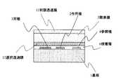
図1は、本発明にかかる第1の実施形態に用いる化学センサ構成の一例を模式的に示す断面図である。図1に示す化学センサは、3極方式の化学センサに構成されており、絶縁性基板1上に、導体からなる作用極2および対極3、ならびに、参照極4が形成されている。これら3極方式の電極系の上には、酵素膜5が形成されており、所謂、酵素電極型の化学センサとされている。なお、この酵素電極では、酵素膜5を固定化する際、電極系と酵素膜5との間に、接着層6を設けている。絶縁性基板1は液透過性を示さず、電極系と液との接触は、液透過性を有する酵素膜5と接着層6とを介して達成される。(1st Embodiment)
FIG. 1 is a cross-sectional view schematically illustrating an example of the configuration of a chemical sensor used in the first embodiment according to the present invention. The chemical sensor shown in FIG. 1 is configured as a three-electrode type chemical sensor, in which a working
この種の化学センサは、その3極方式の各電極間に所定の電位を印加する状態で、測定される電流などの信号を検出するため、各電極に対するリード端子を具えるセンサ・カートリッジ内に組み込まれる形態とされる。作製後、所定の動作特性検査を行った後、乾燥され、酵素膜5や接着層6が不要な湿気(水分)を吸収することを回避するため、乾燥剤と一緒に気密性のパッケージ(袋体)内に封入した形態で、流通過程に乗せられる。 This type of chemical sensor detects a signal such as a measured current in a state in which a predetermined potential is applied between each of the three-electrode electrodes. It is in a form to be incorporated. After the production, a predetermined operation characteristic test is performed and then dried. In order to prevent the enzyme film 5 and the adhesive layer 6 from absorbing unnecessary moisture (moisture), an airtight package (bag) together with a desiccant is used. It is put in the distribution process in a form enclosed in the body.
ユーザーが、前記パッケージ封入された酵素電極型化学センサを使用する場合は、先ず、パッケージを開封し、酵素電極型化学センサと測定回路との間で、対応する電極端子間の接続を行い。次に、電位印加をしない状態で、酵素電極型化学センサを保存液中に浸漬する。この保存液は、通常、一定組成の緩衝液が利用される。保存液とする緩衝液中に浸漬すると、乾燥状態とされていた酵素膜5と接着層6中に液が浸透し、湿潤状態へと変化する。その際、例えば、酵素膜5は液の浸透とともに、乾固した形態から、本来の膨潤した層へと回復する。また、微視的に見た場合、酵素膜5を構成する酵素蛋白質、その固定化を果すマトリックス物質などの各有機物質は、分子間の結合状態、各分子間の相対的配置、配列等は、緩衝液の浸潤程度に応じて、若干の変化を起こす。 When the user uses the enzyme electrode type chemical sensor enclosed in the package, first, the package is opened, and the connection between the corresponding electrode terminals is performed between the enzyme electrode type chemical sensor and the measurement circuit. Next, the enzyme electrode type chemical sensor is immersed in the storage solution without applying a potential. As this storage solution, a buffer solution having a constant composition is usually used. When immersed in a buffer solution serving as a storage solution, the solution permeates into the enzyme film 5 and the adhesive layer 6 that have been in a dry state, and changes to a wet state. At this time, for example, the enzyme membrane 5 recovers from the dried form to the original swollen layer with the penetration of the liquid. Further, when viewed microscopically, each organic substance such as an enzyme protein constituting the enzyme membrane 5 and a matrix substance that achieves immobilization thereof has a binding state between molecules, a relative arrangement and an arrangement between the molecules, and the like. However, slight changes occur depending on the degree of infiltration of the buffer solution.
次いで、作用極2および対極3、ならびに、参照極4の表面全体が、接着層6中に浸透、充満した緩衝液と接触した状態に達した時点で、電極系に所定の電位を印加する。導体、例えば、白金電極で形成されている作用極2と、銀/塩化銀からなる参照極4との間に電位が印加されると、電解液として機能する緩衝液を介して、作用極2と参照極4は、キャパシタを構成する結果、該キャパシタの充電に相当する過程が生じ、作用極表面に電荷が蓄積され、電気二重層が形成される。かかる誘導電流は、電位印加の直後にパルス的に流れ、その後、極く微弱な電流へと減少し、一定となるまでの過渡的時間は数分程度である。 Next, when the entire surface of the working
その際、導体、例えば、白金電極で形成されている作用極2の表面に、誘電体物質からなる表面被覆層が存在していると、この化学センサにおける電気化学的反応の反応効率は、例えば、かかる表面被覆層を通過して、作用極2から、液と接する表面へと電荷の注入される効率にも依存するため、表面被覆層の厚さ、有無によって、影響を受ける。従って、仮に、乾燥状態で保管されている酵素電極型化学センサにおいて、作用極2の表面に形成されている表面被覆層の厚さ、微視的な組成が、かかる酵素電極型化学センサを待機状態で安定に保持する際に達成される、「定常状態」の表面被覆層の厚さ、微視的な組成と相違すると、使用開始直後においては、この化学センサにおける電気化学的反応の反応効率は、「定常状態」における反応効率より偏移しており、待機状態の電位印加を継続する間に、作用極の表面において、「定常状態」の表面被覆層の厚さ、微視的な組成へと徐々に変化させる反応が起こる。 At that time, if a surface coating layer made of a dielectric substance is present on the surface of the working
本発明者が見出した、化学センサを使用開始する際、この初期段階で見出されるセンサ感度特性の不安定さは、前記の過渡的な現象を反映すると推断される。すなわち、乾燥状態で保管されていた酵素電極型化学センサにおける、作用極2と参照極4の表面の微視的状況を、「定常状態」における作用極2の表面の微視的状況へと変化させる、界面での電気化学的反応の詳細を解明するには到っていないが、少なくとも、作用極2と参照極5との間に待機状態にも印加されている測定電位と同じ方向の電位(順方向の電位)によって、その反応が進行することが確認される。加えて、かかる測定電位と同じ方向の電位(順方向の電位)であって、測定電位よりも大きな絶対値を有する電位を印加すると、かかる界面での電気化学的反応速度は急速な促進が達成される。 It is presumed that the instability of the sensor sensitivity characteristic found at the initial stage when the chemical sensor is started to be used, which is found by the present inventors, reflects the above-mentioned transient phenomenon. That is, the microscopic condition of the surface of the working
但し、作用極2と参照極4との間に印加される電位を過度に大きくすると、用いている緩衝液において、溶媒の種類、緩衝液成分、支持電解質自体に応じて、酸化還元反応が電極表面で開始する。すなわち、これら用いている緩衝液に由来する、不要な電気化学的な反応が生じない範囲内(所謂、「電位窓領域」と称される範囲)に、印加電位を選択する必要がある。さらには、この「電位窓領域」の上限には達してないが、順方向の大きな電位を作用極2と参照極4との間に印加すると、作用極2と参照極4との間を流れる微小な電流が、「暗電流」となって、急激に増加し、酵素電極型化学センサ自体の動作不良、酵素膜層の欠損を引き起こす場合もある。 However, if the potential applied between the working
本発明にかかる第一の化学センサによる測定方法では、乾燥状態で保管されていた酵素電極型化学センサにおける、作用極2と参照極4の表面の微視的状況を、「定常状態」における作用極2と参照極4の表面の微視的状況へと速やかに変化させるため、保存液とする緩衝液中に浸漬した後、先ず、測定電位と同じ方向の電位(順方向の電位)であって、測定電位よりも大きな絶対値を有する電位(第一の初期処理電位)を印加して、かかる界面での電気化学的反応速度の急速な促進をおこなって、第一の初期処理時間の間、かかる第一の初期処理電位を印加する間に、測定電位を印加する待機状態では、1〜3日間を要する反応を、例えば、4時間以内に選択される該第一の初期処理時間で達成できる。その後、作用極2と参照極4との間に印加する電位を、測定電位と同一の第二の初期処理電位に変更して、該第二の初期処理電位を印加すると、第一の初期処理電位を印加した際に、作用極2と参照極4の両電極表面に蓄積され、電気二重層を形成している電荷量は、第二の初期処理電位(測定電位)の印加状態で蓄積されるべき電荷量まで減少される。この電極での放電過程自体は、充電過程と同程度の短時間で完了する。一方、両電極表面に蓄積される電荷による電気二重層に付随して、酵素膜5と接着層6とにも、その静電的電界によって誘起されている変化の回復もなされる必要がある。この酵素膜5と接着層6に生じている静電的変化の回復は、より緩やかに進行するため、酵素電極型化学センサ全体が、目標とする「定常状態」における待機時と同様の状態に移行を完了する上では、前記第二の初期処理電位(測定電位)を印加して保持する時間(第二の初期処理時間)を設けることが望ましい。 In the measurement method using the first chemical sensor according to the present invention, the microscopic condition of the surfaces of the working
仮に、かかる第二の初期処理時間を短くしても、化学センサを使用開始する際、この初期段階で見出されるセンサ感度特性の不安定さの主要因は、上述する第一の初期処理工程において排除されており、直後に行った測定では、目標とする「定常状態」の安定した測定結果とは偏移する可能性はあるものの、その後、2回目の測定を実施するまで、待機状態に保持する間に、かかる第二の初期処理工程に相当する、第二の初期処理電位(測定電位)の印加状態における保持が達成される。 Even if the second initial processing time is shortened, when starting to use the chemical sensor, the main factor of the instability of the sensor sensitivity characteristic found at this initial stage is the first initial processing step described above. It has been excluded and the measurement performed immediately after may be shifted from the target stable measurement result in the “steady state”, but is kept in the standby state until the second measurement is performed thereafter In the meantime, the holding of the applied state of the second initial processing potential (measured potential) corresponding to the second initial processing step is achieved.
図1に示す3極方式の化学センサとする際、参照極4として、銀/塩化銀電極を利用し、作用極2と対極3を白金電極で形成する場合、上述する「電位窓領域」と称される範囲は、参照極4とする銀/塩化銀電極を基準として、作用極2の電位を、−0.6V〜1.2Vに設定する範囲にあたる。なお、用いる保存液は、150mMの塩化ナトリウムを含むTES(N−トリス(ヒドロキシメチル)メチル−2−アミノエタンスルホン酸)、pH7の緩衝液など、中性状態の緩衝液が利用できる。 When the three-electrode type chemical sensor shown in FIG. 1 is used, a silver / silver chloride electrode is used as the
酵素電極型化学センサに適合する保存液は、利用されている酵素蛋白質の酵素活性を保持可能な緩衝液であり、通常、塩化ナトリウムや塩化カリウム、塩化カルシウムなどから選ばれる支持電解質と、所望のpHを維持する緩衝剤成分が含まれている。この緩衝剤成分として、使用する酵素の示適pHをも考慮し、維持pH値が選択される。多くの場合、一般的なリン酸緩衝液、あるいは、各種酵素反応に利用されるグッド緩衝液の一群である、アミノプロパンスルホン酸誘導体(MOPSなど)やアミノエタンスルホン酸誘導体(MESなど)、HEPES、PIPESなどが利用できる。 The preservation solution compatible with the enzyme electrode type chemical sensor is a buffer that can retain the enzymatic activity of the enzyme protein used, and is usually a supporting electrolyte selected from sodium chloride, potassium chloride, calcium chloride, and the like. Contains a buffer component to maintain the pH. As the buffer component, the maintenance pH value is selected in consideration of the optimum pH of the enzyme used. In many cases, a group of general phosphate buffers or good buffers used for various enzyme reactions, such as aminopropanesulfonic acid derivatives (such as MOPS), aminoethanesulfonic acid derivatives (such as MES), and HEPES , PIPES, etc. can be used.
通常、保存液には、待機状態において、化学センサに流れるベース電流が小さくなる緩衝液を選択することで、化学センサの電極の劣化を抑制する。一方、本発明にかかる初期処理操作では、作用極と参照極間に印加される電位を増すことで、電極から緩衝液へと注入される電流量を格段に増すことで、かかる電極表面上に存在する表面被覆膜の除去過程を加速する機構である場合、この注入される電流量の増加比率がより高い緩衝液を利用すると、かかる表面被覆膜の除去過程のさらなる加速に効果を有する。作用極と参照極間に印加される電位を同一とする際、同じpH値を維持する緩衝液であっても、緩衝剤成分に依存して、電極から緩衝液へと注入される電流量に差異を有することがある。例えば、緩衝剤成分に利用する化学物質が、電極との間で電子の授受を生じ易い、また、電極表面に近接し易い分子形状、サイズを有するならば、この化学物質との電子授受を介する電極から緩衝液へと注入される電流量の増加が期待される。本発明者が検討したところ、具体的には、(2−ヒドロキシエチル)イミノ−トリス(ヒドロキシメチル)メタン緩衝液(Bi−Tr,Bis)において、ベース電流を増す効果があった。例えば、後述する実施例1に記載する酵素電極型化学センサにおいて、測定電位として、作用極に0.45Vの電位印加する際、保存液組成として、0.1M Bi−Tr,Bis、0.15M NaCl、pH 7を用いると、上述する150mMの塩化ナトリウムを含むTES緩衝液を用いる場合と比較し、待機状態のベース電流は、10nA程度多くの電流を発生する。 Normally, in the standby state, a buffer that reduces the base current flowing through the chemical sensor in the standby state is selected to suppress deterioration of the electrodes of the chemical sensor. On the other hand, in the initial processing operation according to the present invention, the potential applied between the working electrode and the reference electrode is increased, so that the amount of current injected from the electrode into the buffer solution is significantly increased. In the case of a mechanism for accelerating the removal process of the existing surface coating film, the use of a buffer having a higher increasing rate of the amount of injected current has an effect on further accelerating the removal process of the surface coating film. . When the potential applied between the working electrode and the reference electrode is the same, even if the buffer maintains the same pH value, the amount of current injected from the electrode into the buffer depends on the buffer component. May have differences. For example, if the chemical substance used for the buffer component is likely to give and receive electrons to and from the electrode, and has a molecular shape and size that makes it easy to come close to the electrode surface, via the electron transfer with this chemical substance An increase in the amount of current injected from the electrode into the buffer is expected. As a result of the study by the present inventors, specifically, the (2-hydroxyethyl) imino-tris (hydroxymethyl) methane buffer (Bi-Tr, Bis) had the effect of increasing the base current. For example, in the enzyme electrode type chemical sensor described in Example 1 described later, when a potential of 0.45 V is applied to the working electrode as a measurement potential, the composition of the storage solution is 0.1 M Bi-Tr, Bis, 0.15 M When NaCl, pH 7, the base current in the standby state generates about 10 nA more than in the case of using the TES buffer containing 150 mM sodium chloride described above.
例えば、作用極2と対極3を白金電極で形成する場合、前記緩衝液中に添加される過酸化水素の電気化学的反応の開始する作用極2の電位は、参照極とする銀/塩化銀電極を基準として、350mV程度であり、図1に示す酵素電極型化学センサが、酵素タンパク質 グルコースオキシターゼにより、基質のグルコースより、酵素反応で生成する過酸化水素を測定する方式の場合、測定電位は、作用極2の電位を、参照極とする銀/塩化銀電極を基準として、400mV〜700mVの範囲に設定する。前記過酸化水素の電気化学的反応に伴う、応答電流発生は、700mV付近で最大の効率を示すものの、例えば、ビタミンC(アスコルビン酸)などの干渉成分の影響は、かかる700mV以上に作用極2の電位を選択すると急速に増す。その点を考慮すると、測定電位としては、前記の範囲が好適となる。 For example, when the working
それに対して、第一の初期処理工程において、作用極2と参照極4との間に印加される第一の初期処理電位は、測定電位よりも有意に大きな値に選択することが望ましく、従って、参照極として、銀/塩化銀電極を用い、作用極と対極とを白金電極とする際、第一の初期処理電位は、前記緩衝液中において、参照極とする銀/塩化銀電極を基準として、前記測定電位よりも、少なくとも100mV以上大きな印加電位、但し、900mVを超えない範囲に選択すると好ましい。例えば、作用極2の電位を、前記緩衝液中において、参照極とする銀/塩化銀電極を基準として、少なくとも、750mV〜900mVの範囲に選択し、この第一の初期処理時間を4時間以下、少なくとも、1時間を下回らない範囲に選択する。 On the other hand, in the first initial processing step, the first initial processing potential applied between the working
その後、印加電位を変更して、第二の初期処理電位(測定電位)を印加して保持する時間(第二の初期処理時間)は、第一の初期処理電位と第二の初期処理電位(測定電位)との電位変化量が増すとともに、徐々に長く設定することが望ましいものの、この電位変化に際して、電位印加方向の反転は無く、その電位変化量も大きくとも、500mV程度であり、第二の初期処理時間は、1時間以内で十分に安定状態を達成できる。 Thereafter, the applied potential is changed and the time for applying and holding the second initial processing potential (measurement potential) (second initial processing time) is determined by the first initial processing potential and the second initial processing potential ( It is desirable that the potential change with respect to the measurement potential) is increased and gradually set longer. However, in this potential change, there is no reversal of the potential application direction, and the potential change is at most about 500 mV. Can be sufficiently stabilized within one hour.
これらの手順は、酵素電極型化学センサを利用する測定装置本体のソフトに記憶させておき、一連の初期処理操作が完了し、測定電位に保持される待機状態となった段階で、測定可能となったことを報知装置に報知させる形態とすることができる。なお、この報知手段としては、LCDなどの表示装置を用いても良いし、音や振動などを用いても良い。酵素電極型化学センサを利用する測定装置にかかる機構を予め付加しておくことにより、ユーザーは、新しいセンサ・カートリッジを接続した後、第1回目の測定を行う際にも、再現性の良い測定を行うことが可能になる。 These procedures are stored in the software of the measuring device body using the enzyme electrode type chemical sensor, and when a series of initial processing operations are completed and a standby state is held at the measurement potential, measurement is possible. The notification device may be notified of the change. Note that a display device such as an LCD may be used as the notification means, or sound or vibration may be used. By adding a mechanism related to the measuring device using the enzyme electrode type chemical sensor in advance, the user can connect a new sensor cartridge and then perform the first measurement, with good reproducibility. Can be performed.
なお、以上の説明では、酵素電極型化学センサにおける手順を例示したが、同様な手法は、乳酸センサ、有機材料膜からなる選択透過膜を用いた過酸化水素センサなど他の化学センサについても適用できる。さらには、酸素センサのように、測定電位として、作用極の電位を負側に設定する場合にも、この測定電位と同じ印加方向において、絶対値の大きな電位を用いることにより同様に適用することができる。 In the above description, the procedure in the enzyme electrode type chemical sensor has been exemplified, but the same method is applied to other chemical sensors such as a lactic acid sensor and a hydrogen peroxide sensor using a permselective membrane made of an organic material membrane. it can. Further, even when the potential of the working electrode is set to the negative side as the measurement potential, as in the case of an oxygen sensor, the same application is performed by using a potential having a large absolute value in the same application direction as the measurement potential. Can be.
(実施例1)
酵素電極型化学センサとして、図1に示す構成を示す、グルコースセンサを用いた。この酵素電極型化学センサの電極系は、Ptの作用極2、対極3、Ag/AgClの参照極4で構成される3極方式とした。酵素膜5は、グルコースオキシターゼを、アルブミンとグルタルアルデヒドのマトリックスに固定化して形成した。酵素膜5と電極の間には、接着層6としてシランカップリング剤を介在させた。この酵素電極型化学センサを、プラスティック製のカートリッジ7に液密に封入し用いた。カートリッジ7には、グルコースセンサの感応部だけが液と触れるように、窓8を設けた。今後、特に断らない限りカートリッジ7は、かかる酵素電極型化学センサを含むものと定義する。(Example 1)
As the enzyme electrode type chemical sensor, a glucose sensor having the configuration shown in FIG. 1 was used. The electrode system of this enzyme electrode type chemical sensor was a three-electrode system composed of a working
本例では、上記3極方式のグルコースセンサ専用の測定回路として、設計されている本体9を用いた。本体9は、作用極2に、所定の定電位を供給するポテンショスタット回路および測定回路、報知装置10を備えている。図2に、この測定装置の模式外観図を示す。 In the present example, the designed main body 9 was used as a measurement circuit dedicated to the three-pole glucose sensor. The main body 9 includes a potentiostat circuit for supplying a predetermined constant potential to the working
測定は下記の手順で行った。先ず、乾燥剤とともに1年間乾燥保管されたカートリッジ7を取り出し、本体9に接続した。次に、感応部が液に触れるようにカートリッジを保存液に浸漬した。なお、用いた保存液は、150mMの塩化ナトリュウムを含むTES(エヌ・トリス(ハイドロキシメチル)・メチル・2−アミノエタンサルフォニックアシッド)、pH7の緩衝液である。 The measurement was performed according to the following procedure. First, the cartridge 7 dried and stored for one year together with the desiccant was taken out and connected to the main body 9. Next, the cartridge was immersed in the preservation solution such that the sensitive part touched the solution. The preservation solution used was a buffer solution of TES (N-tris (hydroxymethyl) .methyl-2-aminoethanesulfonic acid) containing 150 mM sodium chloride, pH7.
この緩衝液に浸漬した化学センサに対して、基準とする参照極4に対して、作用極2に800mVの電位を印加し、1時間保持した。次に、作用極2に印加する電位を、測定電位である700mVに変更し、さらに1時間保持した後、測定を開始した。図3に、この使用開始操作時の作用極2に印加電位チャートを示す。前記使用開始処理を施した化学センサを用いて、濃度50mg/dlのグルコース溶液を測定したところ、応答電流値として610nAが得られた。なお、この酵素電極型化学センサは、乾燥保管する前に行った特性試験では、濃度50mg/dlのグルコース溶液に対して測定された応答電流値は600nAであった。次に、翌日、24時間待機状態に保持後、同じ測定を繰り返した。この1日経過後、測定された応答電流値は600nAであった。さらに、その後3日間、毎日同じ測定を繰り返し、経日的変化の有無を評価したところ、測定された応答電流値は590〜610nAで推移した。 With respect to the chemical sensor immersed in the buffer solution, a potential of 800 mV was applied to the working
比較のため、同じ製造ロットの、乾燥保管されていたグルコースセンサに関しては、緩衝液に浸漬した後、基準とする参照極4に対して、作用極2に測定電位と同じ700mVの電位を印加して、2時間保持する処理を施した。この処理を施した化学センサを用いて、濃度50mg/dlのグルコース溶液を測定したところ、応答電流値として510nAが得られた。なお、この酵素電極型化学センサも、乾燥保管する前に行った特性試験では、濃度50mg/dlのグルコース溶液に対して測定された応答電流値は600nAであった。次に、翌日、24時間待機状態に保持後、同じ測定を繰り返した。この1日経過後、測定された応答電流値は580nAであった。さらに、その後3日間、毎日同じ測定を繰り返し、経日的変化の有無を評価したところ、測定された応答電流値は590〜610nAで推移した。すなわち、乾燥保管後、緩衝液に浸漬した後、基準とする参照極4に対して、作用極2に測定電位と同じ700mVの電位を印加して、2時間保持する処理では、センサ感度が、本来の水準よりも有意に低く、都合24時間、この待機状態に保持しても、センサ感度は、本来の水準にまでは回復していないことが判明した。なお、計48時間、待機状態に保持した段階では、センサ感度は、本来の水準にまでは回復している。 For comparison, the glucose sensor of the same production lot, which was stored dry, was immersed in a buffer solution, and then a potential of 700 mV was applied to the working
一方、同じ製造ロットの、乾燥保管されていたグルコースセンサに関しては、緩衝液に浸漬した後、基準とする参照極4に対して、作用極2に800mVの電位を印加して、2時間保持する処理を施した。この処理を施した化学センサについて、作用極2に印加する電位を測定電位である700mVに変更し、作用極2と参照極4と間を流れるベース電流が一定になる3分間後に、濃度50mg/dlのグルコース溶液を測定したところ、応答電流値として720nAが得られた。なお、この酵素電極型化学センサも、乾燥保管する前に行った特性試験では、濃度50mg/dlのグルコース溶液に対して測定された応答電流値は600nAであった。次に、翌日、24時間待機状態に保持後、同じ測定を繰り返した。この1日経過後、測定された応答電流値は600nAであった。さらに、その後3日間、毎日同じ測定を繰り返し、経日的変化の有無を評価したところ、測定された応答電流値は590〜610nAで推移した。すなわち、乾燥保管後、緩衝液に浸漬した後、基準とする参照極4に対して、作用極2に800mVの電位を印加して、2時間保持する処理の直後は、センサ感度は、本来の水準よりも有意に高いが、その後、作用極2に印加する電位を測定電位である700mVにして、待機状態に保持すると、遅くとも、1日経過した時点では、センサ感度は、本来の水準で安定化が図られていることが判明した。 On the other hand, with respect to the glucose sensor of the same production lot that has been stored dry, after being immersed in the buffer solution, a potential of 800 mV is applied to the working
図4に、上記の3種の使用開始時の処理を施した、グルコースセンサのセンサ感度(応答電流値)の経日的変化を評価した結果を対比して示す。これらの結果を総合すると、乾燥状態で保管する間に、この酵素電極型化学センサの作用極、対極表面の微視的な状況は、測定電位を印加して、24時間以上保存液中に浸漬して、安定化が図られた状態とは異なった状態に偏移するものの、測定電位よりも有意に高い電位を印加して、保存液中に浸漬、保持する処理を施すことで、電極表面の状態は、本来の安定化した状態へと復することが可能であることが判明した。なお、この高い電位を印加した状態から、通常の測定電位に変更した際、電極表面上に蓄積される電荷に起因する電気二重層の変化は、速やかに行われ、作用極と参照極と間を流れるベース電流が一定になるものの、酵素電極型化学センサ全体として、静電的に偏移した状態の安定化を達成するには、さらに時間を要することが判る。なお、このさらなる安定化には、印加電位の変更量にも依るものの、長くとも、1時間以内の保持で十分であると判断される。 FIG. 4 shows, in comparison, the results of evaluating the daily change of the sensor sensitivity (response current value) of the glucose sensor which has been subjected to the above three types of processes at the start of use. Summarizing these results, during storage in a dry state, the microscopic condition of the working electrode and counter electrode surface of this enzyme electrode type chemical sensor is as follows. Then, although it shifts to a state different from the state where the stabilization was achieved, the electrode surface is treated by applying a potential that is significantly higher than the measured potential and immersing and holding it in the storage solution. Has been found to be able to return to the original stabilized state. Note that when the high potential is applied and the potential is changed to a normal measurement potential, the electric double layer changes due to the electric charge accumulated on the electrode surface quickly, and the electric potential between the working electrode and the reference electrode is changed. It can be seen that, although the base current flowing through becomes constant, the enzyme electrode type chemical sensor as a whole needs more time to stabilize the electrostatically deviated state. In addition, it is determined that holding for one hour or less is sufficient for this further stabilization, although it depends on the amount of change in the applied potential.
すなわち、作製後、乾燥状態で保管されている酵素電極型化学センサについて、使用開始する際、本発明にかかる第一の測定方法に従う、使用開始処理操作を行うことで、その酵素電極型化学センサ本来のセンサ感度への安定化を短時間で達成できることが確認された。この使用開始処理操作を終えた後、センサ感度の安定化がなされ、一定期間、感度較正を行わなくとも、精度、再現性のよい測定を実施することが可能となる。 That is, after the preparation, the enzyme electrode type chemical sensor stored in a dry state, when starting to use, according to the first measurement method according to the present invention, by performing a use start processing operation, the enzyme electrode type chemical sensor It was confirmed that stabilization to the original sensor sensitivity can be achieved in a short time. After the use start processing operation is completed, the sensor sensitivity is stabilized, and it is possible to perform measurement with high accuracy and reproducibility without performing sensitivity calibration for a certain period.
また、以上の結果を踏まえて、かかる酵素電極型化学センサ用の測定装置本体9に関して、上述する使用開始処理操作に対応する印加電位設定、保持時間の条件を、ソフト的に機能追加した。対応して、ハード的にも、上述する一連の使用開始処理操作が完了し、安定した測定が可能となった旨を表示する機構をも付加した。 In addition, based on the above results, with respect to the measuring device main body 9 for the enzyme electrode type chemical sensor, the applied potential setting and the holding time conditions corresponding to the above-mentioned use start processing operation were added as software functions. Correspondingly, in terms of hardware, a mechanism for displaying that the series of use start processing operations described above has been completed and stable measurement has become possible has been added.
例えば、上述する使用開始処理操作機能を付加した測定装置本体9では、
乾燥状態のセンサを測定器本体9に接続してから、
(i)センサが保存液に浸漬される位置に設置(リードスイッチ等で検知)
(ii)電位を印加せずに5分間保持
→有機膜全体が十分に保存液で濡れていない状態で電位を印加すると膜破壊を起こすため。
(iii)750mVで3時間保持
(iv)450mVで1時間保持
(v)450mVはそのままだが、測定器本体部のインジケータが「測定可」となる。
のような、ソフト的な電位印加タイミング制御、ならびに、それに利用するリードスイッチ等で検知機構、測定器本体部のインジケータ部の追加など、ハード的な変更がなされる。For example, in the measuring device main body 9 to which the use start processing operation function described above is added,
After connecting the dry sensor to the measuring instrument body 9,
(I) Installed at the position where the sensor is immersed in the storage solution (detected by reed switch etc.)
(Ii) Hold for 5 minutes without applying a potential → Applying a potential in a state where the entire organic film is not sufficiently wetted with the preservative solution will cause film destruction.
(Iii) Hold at 750 mV for 3 hours (iv) Hold at 450 mV for 1 hour (v) 450 mV remains as it is, but the indicator on the measuring instrument main body becomes “measureable”.
As described above, hardware-related changes such as addition of a detection mechanism and an indicator section of the measuring instrument main body are made by a soft potential application timing control and a reed switch or the like used therefor.
(第2の実施形態)
図5は、本発明にかかる第2の実施形態に用いる化学センサ構成の一例を模式的に示す断面図である。図2に示す化学センサは、3極方式の化学センサに構成されており、絶縁性基板1上に、導体からなる作用極2および対極3、ならびに、参照極4が形成されている。これら3極方式の電極系の上には、酵素膜5が形成されており、所謂、酵素電極型の化学センサとされている。なお、この酵素電極では、酵素膜5の表面側に制限透過膜11を、また、酵素膜5の電極側には選択透過膜12を設けてあり、これらの膜を固定化する際、電極系と選択透過膜12との間に、接着層6を設けている。絶縁性基板1は液透過性を示さず、電極系と液との接触は、液透過性を有する、制限透過膜11、酵素膜5、選択透過膜12、ならびに接着層6とを介して達成される。この最表面に制限透過膜を具える、酵素電極を利用する酵素電極型化学センサの具体例は、例えば、特許掲載公報第2943700号に開示されている。(Second embodiment)
FIG. 5 is a cross-sectional view schematically illustrating an example of a chemical sensor configuration used in the second embodiment according to the present invention. The chemical sensor shown in FIG. 2 is configured as a three-electrode type chemical sensor, in which a working
選択透過膜12は、化学センサの電極表面における電気化学的反応にあずかる、最終的な測定対象物質以外の物質の透過を阻止する機能を有しており、その機能は、編み目構造により大きな分子量を有する分子の透過を阻止したり、さらには、静電的な反発力によりイオンの侵入を阻止したりする膜構造によって発現される。 The permselective membrane 12 has a function of blocking the permeation of substances other than the final substance to be measured, which participate in an electrochemical reaction on the electrode surface of the chemical sensor. It is expressed by a membrane structure that blocks the permeation of the molecules it has, and further blocks the penetration of ions by electrostatic repulsion.
一方、制限透過膜11は、酵素電極における測定対象物質の透過率を制限するものであり、すなわち、酵素膜5における酵素反応の基質物質の透過率を低くすることにより、仮に、測定試料中の基質物質濃度が高い場合でも、単位時間当たりに酵素膜5に達する基質物質量は、かかる酵素膜5中に含有される酵素で定量的に反応産物へと変換可能としている。一般に、酵素膜5に達する基質物質量が過剰になると、単位時間当たりに、酵素膜5中に含有されている、限られた量の酵素により変換される反応産物量には、一定の上限があり、基質物質量と反応産物量との間で定量性が失われ、結果的に、センサ出力飽和と称される状態となる。図5に示す制限透過膜11を設ける構成を採用することで、センサ出力飽和に達する測定試料中の基質物質濃度を格段に高くでき、すなわち、定量性の高い測定が可能な測定試料中の基質物質の濃度範囲、所謂ダイナミックレンジを拡大する機能を有する。さらには、制限透過膜11は、測定試料中の基質物質のみでなく、実際の測定試料中に含まれる種々の夾雑物に対しても、その透過率を制限する機能を示すので、酵素膜5の機能低下の要因となる種々の夾雑物に対する、化学的、物理的な保護膜としての役目をも果している。 On the other hand, the restricted permeable membrane 11 limits the transmittance of the substance to be measured at the enzyme electrode, that is, by lowering the transmittance of the substrate substance of the enzyme reaction in the enzyme membrane 5 to temporarily reduce the transmittance of the sample to be measured. Even when the substrate substance concentration is high, the amount of the substrate substance that reaches the enzyme membrane 5 per unit time can be quantitatively converted into a reaction product by the enzyme contained in the enzyme membrane 5. In general, when the amount of the substrate substance reaching the enzyme membrane 5 becomes excessive, a certain upper limit is imposed on the amount of the reaction product contained in the enzyme membrane 5 and converted by the limited amount of enzyme per unit time. In some cases, quantitativeness is lost between the amount of the substrate substance and the amount of the reaction product, resulting in a state called sensor output saturation. By adopting the configuration in which the limiting permeation membrane 11 shown in FIG. 5 is provided, the concentration of the substrate substance in the measurement sample reaching the sensor output saturation can be significantly increased, that is, the substrate in the measurement sample capable of performing highly quantitative measurement. It has a function of expanding a concentration range of a substance, a so-called dynamic range. Furthermore, the restricted permeable membrane 11 has a function of limiting the transmittance not only of the substrate substance in the measurement sample but also of various contaminants contained in the actual measurement sample. It also plays a role as a chemical and physical protective film against various contaminants which may cause a decrease in the function of the compound.
例えば、グルコースセンサなど、酵素電極型化学センサが測定対象とする測定試料溶液は、血液や尿、排水など、測定対象物質以外の種々の夾雑物質を含むことが多い。このような測定試料の場合、図3に示すような、酵素膜と電極だけの構造では、これらの夾雑物質に因る影響、妨害や干渉を受けやすく、センサ特性の著しい変化を起こすことも少なくない。前記した選択透過膜12や制限透過膜11を設けることにより、酵素電極型化学センサは、このような厳しい環境においても、安定した特性を維持し、高い定量性を発揮できるようになる。 For example, a measurement sample solution to be measured by an enzyme electrode type chemical sensor such as a glucose sensor often contains various contaminants other than the measurement target substance, such as blood, urine, and wastewater. In the case of such a measurement sample, the structure including only the enzyme membrane and the electrode as shown in FIG. 3 is susceptible to interference, interference or interference due to these contaminants, and rarely causes a significant change in sensor characteristics. Absent. By providing the selective permeable membrane 12 and the restricted permeable membrane 11 described above, the enzyme electrode type chemical sensor can maintain stable characteristics and exhibit high quantitative performance even in such a severe environment.
しかしながら、この選択透過膜12や制限透過膜11を設ける構造では、溶媒の水、過酸化水素分子や水酸化物イオン(OH-)などの低分子種に関しては、所望の透過特性を確保されているものの、例えば、アスコルビン酸(ビタミンC)や、基質のグルコース程度の分子サイズを有する可溶性物質やイオン種ですら、その透過特性が大幅に制限されている。そのため、図3に示すような、酵素膜と電極だけの構造と比較して、図5に示す選択透過膜12や制限透過膜11を設ける構造では、例えば、作用極2や対極3の表面に存在する表面被膜層が、可溶性物質に変換されても、この作用極2や対極3の表面近傍から、選択透過膜12や制限透過膜11を経由して、センサ外へと排出されるに要する時間は長くなる傾向がある。However, in the structure in which the permselective membrane 12 and the restricted permeation membrane 11 are provided, desired permeation characteristics are secured for low molecular species such as water as a solvent, hydrogen peroxide molecules, and hydroxide ions (OH− ). However, even for example, ascorbic acid (vitamin C), and even soluble substances and ionic species having a molecular size similar to that of glucose as a substrate, the permeation characteristics are greatly restricted. Therefore, as compared with the structure of only the enzyme membrane and the electrode as shown in FIG. 3, the structure in which the selective permeable membrane 12 and the restricted permeable membrane 11 shown in FIG. Even if the existing surface coating layer is converted into a soluble substance, it is required to be discharged from the vicinity of the surface of the working
この図5に示す構造の酵素電極型化学センサの場合にも、本発明にかかる第一の測定方法に従って、乾燥状態で保管されているセンサを使用開始する際、第一の初期処理工程において、保存液に用いる緩衝液中において、参照極とする銀/塩化銀電極を基準として、測定電位よりも有意に大きな値に選択する印加電位、例えば、少なくとも100mV以上大きな印加電位、但し、900mVを超えない範囲に選択される第一の初期処理電位を、白金電極からなる作用極2と参照極4との間に印加して、保持することで、作用極2や対極3の表面に存在する表面被膜層を速やかに除去することが可能である。なお、この第一の初期処理工程における、作用極2と参照極4との間に印加される第一の初期処理電位の好適な範囲は、用いる保存液と、作用極2と参照極4の導電体材料が同じであれば、図3に示すような、酵素膜と電極だけの構造と、図5に示す選択透過膜12や制限透過膜11を設ける構造との間で、本質的には同じものとなる。さらには、作用極2や対極3の表面に存在する表面被膜層が、可溶性物質に変換され、さらに、選択透過膜12や制限透過膜11を経由して、センサ外へと排出されるまでに要する時間は、図3に示すような、酵素膜と電極だけの構造と比較すると長くなるものの、この第一の初期処理時間は4時間を超えない範囲にすることが可能である。 Also in the case of the enzyme electrode type chemical sensor having the structure shown in FIG. 5, when starting to use the sensor stored in a dry state according to the first measurement method according to the present invention, in the first initial processing step, In the buffer solution used for the preservation solution, an applied potential that is selected to a value significantly larger than the measured potential with respect to a silver / silver chloride electrode serving as a reference electrode, for example, an applied potential that is at least 100 mV or more, but exceeds 900 mV. By applying and holding a first initial processing potential selected in a range not present between the working
一方、その後、印加電位を変更して、第二の初期処理電位(測定電位)を印加して保持する時間(第二の初期処理時間)に関しては、図5に示す構造の酵素電極型化学センサの場合でも、第一の初期処理電位と第二の初期処理電位(測定電位)との電位変化量が増すとともに、徐々に長く設定することが望ましいものの、この電位変化に際して、電位印加方向の反転は無く、その電位変化量も大きくとも、500mV程度であり、第二の初期処理時間は、1時間以内で十分に安定状態を達成できる。 On the other hand, after that, the applied potential is changed and the second initial processing potential (measurement potential) is applied and held (second initial processing time) with respect to the enzyme electrode type chemical sensor having the structure shown in FIG. In this case as well, the potential change between the first initial processing potential and the second initial processing potential (measurement potential) increases, and it is desirable that the potential is gradually set longer. However, the amount of change in the potential is at most about 500 mV, and the second initial processing time can sufficiently achieve a stable state within one hour.
なお、図5に示す選択透過膜12や制限透過膜11を設ける構造であっても、乾燥状態で保管されているセンサを使用開始する際、保存液に用いる緩衝液中において、作用極2と参照極4との間に測定電位と同じ電位を印加して、長時間保持すると、徐々に本来のセンサ感度まで回復するものの、その回復過程に要する時間は、1日以上となり、場合によっては、2〜3日を経た時点で、漸く本来のセンサ感度に安定化される。それと比較すると、図5に示す選択透過膜12や制限透過膜11を設ける構造では、図3に示す酵素膜と電極だけの構造と比較すると、長い時間を必要とするものの、本発明にかかる第一の測定方法に従って、初期処理操作を施すことで、本来のセンサ感度へと安定化が達成される期間を、なんら初期処理操作を施さない場合と比較すると、長くとも6時間以下と、格段に短縮することが可能である。 Note that, even when the selective permeation membrane 12 and the restricted permeation membrane 11 are provided as shown in FIG. 5, when the sensor stored in a dry state is started to be used, the working
(実施例2)
本実施例2では、酵素電極型化学センサとして、図5に示す構成を示す、グルコースセンサを用いた。この酵素電極型化学センサの電極系は、Ptの作用極2、対極3、Ag/AgClの参照極4で構成される3極方式とした。酵素膜5は、グルコースオキシターゼを、アルブミンとグルタルアルデヒドのマトリックスに固定化した固定化酵素膜であり、電極上に、接着層6としてシランカップリング剤を介在させて、イオン交換樹脂からなる選択透過膜12を、引き続き、酵素膜5を設け、最表面を、フッ素系樹脂からなる制限透過膜11で被覆する形態とされている。この酵素電極型化学センサを、プラスティック製のカートリッジ7に液密に封入し用いた。カートリッジ7には、グルコースセンサの感応部だけが液と触れるように、窓8を設けた。(Example 2)
In Example 2, a glucose sensor having the configuration shown in FIG. 5 was used as the enzyme electrode type chemical sensor. The electrode system of this enzyme electrode type chemical sensor was a three-electrode system composed of a working
この制限透過膜11を設けるセンサでは、測定可能なグルコースの濃度範囲が広がるため、種々のグルコース濃度を示す試料溶液に対して、予め希釈操作を施し、グルコース濃度の調整を行わなくとも、高い定量性の測定が可能となる。また、選択透過膜12の作用により、基質グルコースから生成する酵素反応産物である過酸化水素は、この選択透過膜12を透過するものの、それ以外の妨害物質、例えば、アスコルビン酸(ビタミンC)などの干渉物質による影響を受けにくくなっている。 In the sensor provided with the restricted permeation membrane 11, the measurable glucose concentration range is widened. Therefore, a high quantification can be performed without performing a dilution operation on the sample solution having various glucose concentrations in advance and adjusting the glucose concentration. Sex can be measured. In addition, hydrogen peroxide, which is an enzyme reaction product generated from substrate glucose by the action of the permselective membrane 12, permeates through the permselective membrane 12, but other interfering substances such as ascorbic acid (vitamin C) and the like. Susceptible to interfering substances.
実施例1と同様に、本発明にかかる初期処理操作の手法を適用する際、その条件の最適化を図った。その条件検討の結果、測定電位として、基準とする参照極4に対して、作用極2に450mVの電位を印加する場合、第一の初期処理電位として、基準とする参照極4に対して、作用極2に750mVの電位を印加し、この第一の初期処理時間として、4時間保持し、次に、作用極2に印加する電位を450mVに変更し、第二の初期処理時間として、1時間保持した後、測定を開始すると、高い再現性で本来のセンサ感度への安定化が達成されることが判った。濃度500mg/dlのグルコース溶液を測定したところ、応答電流値として100nAが得られた。なお、この酵素電極型化学センサは、乾燥保管する前に行った特性試験では、濃度500mg/dlのグルコース溶液に対して測定された応答電流値は100nAであった。さらに、その後4日間、毎日同じ測定を繰り返し、経日的変化の有無を評価したところ、測定された応答電流値は100nA±5nAの範囲で推移した。 As in the first embodiment, when applying the method of the initial processing operation according to the present invention, optimization of the conditions was attempted. As a result of the examination of the conditions, when a potential of 450 mV is applied to the working
比較のため、同じ製造ロットの、乾燥保管されていたグルコースセンサに関しては、緩衝液に浸漬した後、基準とする参照極4に対して、作用極2に測定電位と同じ450mVの電位を印加して、濃度500mg/dlのグルコース溶液を測定したところ、初期における応答電流値は、40nA未満であった。なお、この酵素電極型化学センサも、乾燥保管する前に行った特性試験では、濃度500mg/dlのグルコース溶液に対して測定された応答電流値は100nAであった。さらに、その後4日間、毎日同じ測定を繰り返し、経日的変化の有無を評価した。1日経過した時点では、測定された応答電流値は80nAに回復しているものの、3日間を経過した時点で、最終的に、センサ感度が本来の値に安定化したことが確認された。 For comparison, for a glucose sensor of the same production lot, which was stored dry, after immersion in a buffer solution, a potential of 450 mV, the same as the measured potential, was applied to the working
図6に、上記の2種の使用開始時の処理を施した、グルコースセンサのセンサ感度(応答電流値)の経日的変化を評価した結果を対比して示す。この対比によった、本発明にかかる第一の測定方法に従った、使用開始時の初期処理手法は、図5に示す選択透過膜12や制限透過膜11を設ける構造の酵素電極型化学センサにおいて、より利点が大きいと判断される。 FIG. 6 shows a comparison of the results of evaluating the daily change of the sensor sensitivity (response current value) of the glucose sensor which has been subjected to the above two types of processing at the start of use. Based on this comparison, the initial processing method at the start of use according to the first measurement method according to the present invention is an enzyme electrode type chemical sensor having a structure in which a selective permeable membrane 12 and a restricted permeable membrane 11 shown in FIG. 5 are provided. , It is determined that the advantage is greater.
(第3の実施形態)
図5に示す選択透過膜12と制限透過膜11を設ける構成の酵素電極型化学センサについても、上述する第2の実施形態に記載する初期処理操作を施すことで、使用開始から安定したセンサ感度が得られるものの、その後、長期間使用すると、徐々にセンサ感度が低下してくることが分かった。(Third embodiment)
Also for the enzyme electrode type chemical sensor having the configuration in which the selective permeable membrane 12 and the restricted permeable membrane 11 shown in FIG. 5 are provided, by performing the initial processing operation described in the above-described second embodiment, the sensor sensitivity is stabilized from the start of use. However, it was found that the sensor sensitivity gradually decreased after long-term use.
長期間使用する間に見られるセンサ感度の低下は、測定を繰り返すことに伴い、例えば、化学センサ表面に妨害物質が吸着する、あるいは、電極表面への妨害物質の吸着等がその一因と考えられるが、本発明者は、測定をしないで、保存液中に、測定電位を印加して放置する(待機状態に保持する)場合でも、同様のセンサ感度の経時的な低下が生じることを見出した。すなわち、実際の測定試料中に存在する各種の妨害物質が存在していない場合でも、緩衝液中で、測定電位を印加して放置する(待機状態に保持する)間に、何らかのセンサ感度の低下を引き起こす、電極表面への表面被覆層などの形成が緩やかに進行することが判明した。 The decrease in sensor sensitivity observed during long-term use is considered to be caused by, for example, interfering substances adsorbing on the chemical sensor surface or interfering substances adsorbing on the electrode surface due to repeated measurement. However, the present inventor has found that a similar decrease in sensor sensitivity occurs over time even when the measurement potential is applied to the preservation solution without measurement and the measurement solution is left (held in a standby state). Was. In other words, even when various interfering substances present in the actual measurement sample are not present, a decrease in sensor sensitivity occurs during application of the measurement potential in the buffer and standing (holding in a standby state). It has been found that the formation of a surface coating layer on the electrode surface, which causes the above, proceeds slowly.
化学センサ表面に妨害物質が吸着する、あるいは、電極表面への妨害物質の吸着等に起因するセンサ感度の低下に対しては、先に述べた各種の酵素電極の再活性化処理が利用可能であるが、これら外因性の妨害物質でなく、保存液に利用する緩衝液中で生じる、内因性の表面被覆層形成に対しては、本発明にかかる第二の測定方法に従った、フレッシュ処理操作が有効である。 For the reduction of sensor sensitivity due to the adsorption of interfering substances on the chemical sensor surface or the adsorption of interfering substances on the electrode surface, the various types of enzyme electrode reactivation treatment described above can be used. However, instead of these exogenous interfering substances, an endogenous surface coating layer formed in a buffer solution used for a preservation solution is treated by a fresh treatment according to the second measurement method according to the present invention. The operation is valid.
具体的には、化学センサを、所定の期間使用する毎に、待機状態の化学センサについて、緩衝液中に浸漬したまま、作用極と参照極との間に、測定電位と同一方向の電位であって、測定電位よりも大きな絶対値を示す第一のリフレッシュ処理電位を印加して、所定の第一のリフレッシュ処理時間保持する第一のリフレッシュ処理工程を施し、この第一のリフレッシュ処理工程の終了後、作用極と参照極との間に印加する電位を測定電位と同一の第二のリフレッシュ処理電位に変更して、第二のリフレッシュ処理時間、待機状態に保持とするリフレッシュ待機処理工程とを設けることで、前記内因性のセンサ感度低下の回復がなされる。 Specifically, every time the chemical sensor is used for a predetermined period, the chemical sensor in the standby state is immersed in the buffer solution, and between the working electrode and the reference electrode, at a potential in the same direction as the measurement potential. Then, a first refresh processing potential showing an absolute value larger than the measured potential is applied, and a first refresh processing step of holding a predetermined first refresh processing time is performed. After the end, the potential applied between the working electrode and the reference electrode is changed to the same second refresh processing potential as the measurement potential, the second refresh processing time, a refresh standby processing step of holding the standby state Is provided, the endogenous decrease in sensor sensitivity is recovered.
このリフレッシュ処理において利用する、第一のリフレッシュ処理電位は、上述する使用開始時の初期処理で利用される、第一の初期処理電位と同様の範囲に選択することが望ましい。すなわち、好適な範囲は、両者で一致したものとなる。一方、第一のリフレッシュ処理時間は、一般に、第一の初期処理時間と比較すると、相当に短い時間とすることができる。具体的には、第一のリフレッシュ処理時間は、1時間程度に選択できる。一方、第二のリフレッシュ処理時間は、印加電位の変更に伴う、静電的変化を解消するに要する時間であり、本質的に、第二の初期処理時間と同様の範囲に選択するとよい。なお、第一のリフレッシュ処理時間は、第一の初期処理時間と比較すると、相当に短い時間であるので、第二のリフレッシュ処理時間は、第二の初期処理時間よりも若干短い時間、例えば、30分間程度としても、問題ないものとなる。 It is desirable that the first refresh processing potential used in the refresh processing be selected in the same range as the first initial processing potential used in the above-described initial processing at the start of use. That is, the preferred range is the same in both cases. On the other hand, the first refresh processing time can generally be considerably shorter than the first initial processing time. Specifically, the first refresh processing time can be selected to be about one hour. On the other hand, the second refresh processing time is a time required to eliminate an electrostatic change due to a change in the applied potential, and may be essentially selected in the same range as the second initial processing time. Since the first refresh processing time is considerably shorter than the first initial processing time, the second refresh processing time is slightly shorter than the second initial processing time, for example, Even if it is about 30 minutes, there is no problem.
この本発明にかかる第二の測定方法に従った、フレッシュ処理操作は、前記内因性のセンサ感度低下の回復を目的とするものであり、測定試料に由来する外因性の妨害物質等に由来するセンサ感度低下の回復を目的とする、従来の酵素電極の再活性化処理技術のように、測定毎にこの処理を行うよりも、測定頻度に依存するものの、定期的にリフレッシュ動作を組み込むことが有効である。この定期的にリフレッシュ操作を施すことにより、内因性のセンサ感度低下の回復を図り、初期のセンサ感度を長期間維持することができる。 According to the second measurement method according to the present invention, the fresh treatment operation aims at restoring the intrinsic sensor sensitivity decrease, and is derived from an extrinsic interfering substance or the like derived from the measurement sample. As with the conventional enzyme electrode reactivation processing technology for the purpose of recovering from sensor sensitivity degradation, it is more dependent on the measurement frequency, but it is necessary to incorporate a refresh operation periodically, rather than performing this processing for each measurement. It is valid. By performing the refresh operation periodically, it is possible to recover the intrinsic sensor sensitivity decrease and maintain the initial sensor sensitivity for a long time.
(実施例3)
実施例2と同じ構造のグルコースセンサ10本を用いて、2ヶ月に渡り、公称グルコース濃度280mg/dlのコントロール尿(Baio Rad社製アブノーマル)を、定期的に測定した。10本のセンサを、5本ずつの群に分け、一方の群は、1週間に一度、リフレッシュ処理として、基準とする参照極4に対して、作用極2に測定電位より高い750mVの電位を印加して、30分間保持した後、作用極2に印加する電位を、測定電位と同じ450mVに変更し、30分以上経過した時点で、測定を行った。一方、他方の群は、かかるリフレッシュ処理は施さず、待機状態の際にも、作用極2に測定電位と同じ450mVの定電位を連続印加した。(Example 3)
Using 10 glucose sensors having the same structure as in Example 2, control urine (abnormal manufactured by BioRad) having a nominal glucose concentration of 280 mg / dl was periodically measured for 2 months. The ten sensors are divided into groups of five, and one of the groups is configured to apply a 750 mV potential higher than the measured potential to the working
これら二つの群について、上記のコントロール尿を定期的に測定した測定結果の経時的変化を比較した。図7に、その対比結果の一例を示す。両群ともに、各センサにおいて、若干のバラツキは見られるものの、その経時的変化の傾向は、各群内では一致している。すなわち、前記の定期的にリフレッシュ処理を実施する群では、この期間内では、ほぼ同じ測定値が得られ、センサ感度の維持が図られている。一方、リフレッシュ処理を実施していない群では、測定値は経時的に低下し、2ヶ月後には、初期の測定値の2/3になってしまっている。 For these two groups, the time-dependent changes in the measurement results obtained by periodically measuring the control urine were compared. FIG. 7 shows an example of the comparison result. In both groups, although there is some variation in each sensor, the tendency of the change over time is the same in each group. That is, in the group in which the refresh processing is periodically performed, substantially the same measured value is obtained during this period, and the sensor sensitivity is maintained. On the other hand, in the group in which the refresh processing has not been performed, the measured value decreases over time, and after two months, the measured value is 2 of the initial measured value.
なお、コントロール尿を定期的に測定することに付随する、外因性の妨害物質等に由来するセンサ感度低下に加えて、保存液に利用する緩衝液中で待機状態に維持するのみで生じる、内因性のセンサ感度低下が存在することも、別途確認した。この内因性のセンサ感度低下を起こした場合にも、前記の条件でリフレッシュ処理を実施すると、センサ感度は元の水準に回復した。 In addition, in addition to the decrease in sensor sensitivity due to exogenous interfering substances, etc., which accompany the periodic measurement of control urine, intrinsic It was also separately confirmed that there was a decrease in the sensitivity of the sensor. Even when the intrinsic sensor sensitivity was lowered, the sensor sensitivity was restored to the original level when the refresh processing was performed under the above conditions.
以上の結果から、本発明にかかる第二の測定方法に従った、フレッシュ処理操作は、内因性のセンサ感度低下に有効であるのみならず、コントロール尿を定期的に測定することに付随する、外因性の妨害物質等に由来するセンサ感度低下が存在する際にも、酵素電極の再活性化に有効であることが分かった。加えて、長期に渡り、センサ感度を維持するには、測定の有無に関わらず、定期的にリフレッシュ処理を行うことが最適でなると判断される。 From the above results, according to the second measurement method according to the present invention, the fresh treatment operation is not only effective in reducing the intrinsic sensor sensitivity, but also accompanies the periodic measurement of control urine. It has been found that it is effective in reactivating the enzyme electrode even when there is a decrease in sensor sensitivity due to an exogenous interfering substance or the like. In addition, in order to maintain the sensor sensitivity for a long period of time, it is determined that it is optimal to periodically perform the refresh process regardless of the presence or absence of the measurement.
以上の観点から、酵素電極型化学センサ用の測定装置本体9について、測定回数が所定の回数を超えるか、所定の時間が経過した時点で、自動的に上述するリフレッシュ処理操作に対応する印加電位設定、保持時間の条件を、ソフト的に機能追加した。対応して、ハード的にも、上述する一連のリフレッシュ処理操作が完了し、安定した測定が可能となった旨を表示する機構をも付加した。 In view of the above, when the number of times of measurement exceeds a predetermined number of times or a predetermined time elapses, the applied potential corresponding to the refresh processing operation described above is automatically measured for the measurement device body 9 for the enzyme electrode type chemical sensor. Setting and holding time conditions are added as software. Correspondingly, in terms of hardware, a mechanism for displaying that the above-described series of refresh processing operations have been completed and stable measurement has become possible has been added.
本発明を、酵素電極を利用する化学センサに適用した際、長期間に渡り初期の特性を維持することが出来る。また、本発明にかかる化学センサにおいては、リフレッシュ動作をした直後を除けば特別な待機時間を必要としないので、通常は短い間隔で繰り返し測定を行うことができる。 When the present invention is applied to a chemical sensor using an enzyme electrode, the initial characteristics can be maintained for a long period of time. Further, in the chemical sensor according to the present invention, no special standby time is required except immediately after the refresh operation, so that the measurement can be repeatedly performed at short intervals.
加えて、本発明を、酵素電極を利用する化学センサに適用することで、長期間乾燥状態にあった酵素電極の特性を速やかに作製直後の特性に戻すことができる。また、感度が常に一定に出来るため、較正をほとんどしなくても長期間に渡り精度の良い測定をすることが出来る。また、従来に比べ短い間隔で繰り返し測定することが可能になる。 In addition, by applying the present invention to a chemical sensor using an enzyme electrode, the characteristics of the enzyme electrode that has been in a dry state for a long time can be quickly returned to the characteristics immediately after production. In addition, since the sensitivity can be kept constant, accurate measurement can be performed over a long period of time without performing any calibration. In addition, it is possible to repeatedly measure at a shorter interval than before.
1 絶縁性基板
2 作用極
3 対極
4 参照極
5 酵素膜
6 接着層
7 カートリッジ
8 窓
9 本体
10 報知装置
11 制限透過膜
12 選択透過膜
101 セル
102 酵素膜
103 作用極
104 対極DESCRIPTION OF
Claims (13)
Translated fromJapanese前記化学センサに対して、待機中、保存液とする所定の組成の緩衝液中に浸漬し、作用極と参照極との間に所定の測定電位を印加して保持し、
測定時には、前記緩衝液に代えて、測定試料中に浸漬し、作用極と参照極との間に印加される前記測定電位を利用する、電気化学的反応によって発生する電流量変化に基づき、測定試料中に含有される特定物質の濃度を測定する方式による測定方法であり、
該化学センサを使用開始する際、
乾燥状態の該化学センサを前記緩衝液中に浸漬し、前記作用極表面と参照極表面とを該緩衝液に接触させた後、
作用極と参照極との間に、前記測定電位と同一方向の電位であって、該測定電位よりも大きな絶対値を示す第一の初期処理電位を印加して、該化学センサを所定の第一の初期処理時間の間、前記緩衝液中にて保持する第一の初期処理工程と、
該第一の初期処理工程の終了後、前記緩衝液中に浸漬したまま、作用極と参照極との間に印加する電位を前記測定電位と同一の第二の初期処理電位に変更して、前記化学センサを該待機状態で保持する第二の初期処理工程とを設け、
該第二の初期処理工程を終えた後、該化学センサを測定試料の測定に供する手順を具えることを特徴とする化学センサによる測定方法。A method of measuring the concentration of a specific substance contained in a measurement sample using a chemical sensor including at least a working electrode and a reference electrode,
For the chemical sensor, during standby, immersed in a buffer solution of a predetermined composition as a storage solution, applying and holding a predetermined measurement potential between the working electrode and the reference electrode,
At the time of measurement, instead of the buffer solution, immersed in a measurement sample, and using the measurement potential applied between the working electrode and the reference electrode, based on a change in the amount of current generated by an electrochemical reaction, A method for measuring the concentration of a specific substance contained in a sample,
When starting to use the chemical sensor,
After the chemical sensor in a dry state is immersed in the buffer solution, and the working electrode surface and the reference electrode surface are brought into contact with the buffer solution,
Applying a first initial processing potential between the working electrode and the reference electrode in the same direction as the measurement potential and indicating an absolute value greater than the measurement potential, and causing the chemical sensor to move to a predetermined first potential. During one initial processing time, a first initial processing step of holding in the buffer,
After completion of the first initial processing step, while immersed in the buffer solution, change the potential applied between the working electrode and the reference electrode to the same second initial processing potential as the measurement potential, And a second initial processing step of holding the chemical sensor in the standby state,
A method for measuring with a chemical sensor, comprising a step of subjecting the chemical sensor to measurement of a measurement sample after completing the second initial processing step.
該参照極は、前記緩衝液と接触した際、作用極との間に所定の化学ポテンシャル差を有する材料で構成され、
該参照極を基準として、作用極の電位を設定することで、作用極と参照極との間に、所望の電位が印加する状態として、
前記測定電位、第一の初期処理電位、第二の初期処理電位の印加は、
前記緩衝液中における参照極の電位と作用極の電位との間の電位差が、それぞれ前記測定電位、第一の初期処理電位、第二の初期処理電位に相当する電位差を与えるように設定することを特徴とする請求項2に記載の方法。The chemical sensor has a counter electrode in addition to the working electrode and the reference electrode,
The reference electrode is made of a material having a predetermined chemical potential difference with the working electrode when contacted with the buffer solution,
With the reference electrode as a reference, by setting the potential of the working electrode, a state in which a desired potential is applied between the working electrode and the reference electrode,
The measurement potential, the first initial processing potential, the application of the second initial processing potential,
The potential difference between the potential of the reference electrode and the potential of the working electrode in the buffer solution is set to give a potential difference corresponding to the measurement potential, the first initial processing potential, and the second initial processing potential, respectively. The method according to claim 2, characterized in that:
測定に際して、作用極と参照極との間に印加される前記測定電位は、
前記緩衝液中において、該参照極とする銀/塩化銀電極を基準として、400〜700mVの範囲に選択される作用極の電位で得られる印加電位であることを特徴とする請求項3に記載の方法。A silver / silver chloride electrode is used as the reference electrode, a working electrode and a counter electrode are platinum electrodes,
At the time of measurement, the measurement potential applied between the working electrode and the reference electrode is:
4. The applied potential obtained in the buffer at a potential of a working electrode selected from a range of 400 to 700 mV based on a silver / silver chloride electrode serving as the reference electrode. the method of.
前記緩衝液中において、参照極とする銀/塩化銀電極を基準として、該作用極と対極とにおいて水の電気分解反応の開始する印加電位を印加電位最上限値と、前記測定電位を印加電位最下限値と、それぞれ定義し、
該印加電位上限値と印加電位下限値との差異で定義される最上限・最下限電位差を用いて、
前記測定電位よりも、該最上限・最下限電位差の10%以上大きな印加電位であって、前記印加電位上限値よりも、少なくとも200mV以上小さな印加電位の範囲に選択することを特徴とする請求項3また4に記載の方法。In the first initial processing step, the first initial processing potential applied between the working electrode and the reference electrode,
In the buffer, the applied potential at which the electrolysis reaction of water starts at the working electrode and the counter electrode is defined as the upper limit of the applied potential, and the measured potential is defined as the applied potential with respect to the silver / silver chloride electrode serving as the reference electrode. Define the lower limit and each,
Using the uppermost and lowermost potential differences defined by the difference between the applied potential upper limit and the applied potential lower limit,
The applied potential is selected to be in an applied potential range that is 10% or more of the uppermost / lowermost potential difference than the measured potential, and is at least 200 mV or less than the applied potential upper limit value. 3. The method according to 3 or 4.
前記第一の初期処理工程において、作用極と参照極との間に印加される前記第一の初期処理電位は、
前記緩衝液中において、参照極とする銀/塩化銀電極を基準として、
前記測定電位よりも、少なくとも100mV以上大きな印加電位であって、900mVを超えない範囲に選択することを特徴とする請求項4に記載の方法。When a silver / silver chloride electrode is used as the reference electrode and the working electrode and the counter electrode are platinum electrodes,
In the first initial processing step, the first initial processing potential applied between the working electrode and the reference electrode,
In the buffer, a silver / silver chloride electrode serving as a reference electrode is used as a reference.
The method according to claim 4, wherein the applied potential is at least 100 mV or more higher than the measured potential and is selected not to exceed 900 mV.
前記第一の初期処理工程において、作用極と参照極との間に印加される前記第一の初期処理電位は、
前記緩衝液中において、参照極とする銀/塩化銀電極を基準として、
少なくとも、750mV〜900mVの範囲に選択し、
前記第一の初期処理時間を4時間以下、少なくとも、1時間を下回らない範囲に選択することを特徴とする請求項4に記載の方法。When a silver / silver chloride electrode is used as the reference electrode and the working electrode and the counter electrode are platinum electrodes,
In the first initial processing step, the first initial processing potential applied between the working electrode and the reference electrode,
In the buffer, a silver / silver chloride electrode serving as a reference electrode is used as a reference.
Select at least the range of 750mV to 900mV,
5. The method according to claim 4, wherein the first initial processing time is selected to be less than 4 hours, at least not less than 1 hour.
該作用極、対極、参照極は、絶縁性基板上に形成されており、
少なくとも、作用極の表面上に固定化された酵素膜層を設けてなる酵素電極を利用する電流検出型化学センサであることを特徴とする請求項3〜9に記載の方法。The chemical sensor is a three-electrode sensor having a counter electrode in addition to the working electrode and the reference electrode,
The working electrode, the counter electrode, and the reference electrode are formed on an insulating substrate,
The method according to any one of claims 3 to 9, wherein the method is a current detection type chemical sensor using an enzyme electrode having at least an enzyme membrane layer immobilized on the surface of a working electrode.
前記化学センサに対して、待機中、保存液とする所定の組成の緩衝液中に浸漬し、作用極と参照極との間に所定の測定電位を印加して保持し、
測定時には、前記緩衝液に代えて、測定試料中に浸漬し、作用極と参照極との間に印加される前記測定電位を利用する、電気化学的反応によって発生する電流量変化に基づき、測定試料中に含有される特定物質の濃度を測定する方式による測定方法であり、
該化学センサを、所定の期間使用する毎に、
待機状態の該化学センサについて、前記緩衝液中に浸漬し、前記作用極表面と対極表面とを該緩衝液に接触させた状態で、
作用極と参照極との間に、前記測定電位と同一方向の電位であって、該測定電位よりも大きな絶対値を示す第一のリフレッシュ処理電位を印加して、該化学センサを前記緩衝液中にて、所定の第一のリフレッシュ処理時間保持する第一のリフレッシュ処理工程と、
該第一のリフレッシュ処理工程の終了後、前記緩衝液中に浸漬したまま、作用極と参照極との間に印加する電位を前記測定電位と同一の第二のリフレッシュ処理電位に変更して、前記化学センサを第二のリフレッシュ処理時間、待機状態に保持するリフレッシュ待機処理工程とを設け、
該リフレッシュ待機処理工程を終えた後、再び該化学センサを測定試料の測定に供する手順を具えることを特徴とする化学センサによる測定方法。A method of measuring the concentration of a specific substance contained in a measurement sample using a chemical sensor including at least a working electrode and a reference electrode,
For the chemical sensor, during standby, immersed in a buffer solution of a predetermined composition as a storage solution, applying and holding a predetermined measurement potential between the working electrode and the reference electrode,
At the time of measurement, instead of the buffer solution, immersed in a measurement sample, and using the measurement potential applied between the working electrode and the reference electrode, based on a change in the amount of current generated by an electrochemical reaction, A method for measuring the concentration of a specific substance contained in a sample,
Each time the chemical sensor is used for a predetermined period,
For the chemical sensor in a standby state, immersed in the buffer solution, with the working electrode surface and the counter electrode surface in contact with the buffer solution,
Applying a first refresh processing potential between the working electrode and the reference electrode, the potential being in the same direction as the measurement potential and indicating an absolute value greater than the measurement potential, and causing the chemical sensor to react with the buffer solution. A first refresh processing step of holding a predetermined first refresh processing time,
After completion of the first refresh processing step, while immersed in the buffer solution, change the potential applied between the working electrode and the reference electrode to the same second refresh processing potential as the measurement potential, A refresh standby processing step of holding the chemical sensor in a second refresh processing time, a standby state,
A method for measuring with a chemical sensor, comprising a step of again using the chemical sensor for measurement of a measurement sample after completing the refresh standby processing step.
該測定装置は、
少なくとも作用極と参照極とを具える化学センサと、
少なくとも、前記作用極と参照極との間に電位を印加する手段と、該化学センサにより測定される信号を検出する手段とを具える信号検出回路に加えて、
該化学センサを使用開始する際に、
乾燥状態の該化学センサを前記緩衝液中に浸漬し、前記作用極表面と参照極表面とを該緩衝液に接触させた状態で、作用極と参照極との間に、前記測定電位と同一方向の電位であって、該測定電位よりも大きな絶対値を示す前記第一の初期処理電位を、前記第一の初期処理時間の間印加する機構と、
引き続き、該化学センサを前記緩衝液中に浸漬したまま、作用極と参照極との間に印加する電位を前記測定電位と同一の第二の初期処理電位に変更して、該第二の初期処理電位を前記第二の初期処理時間の間印加する機構と、
前記二段階の初期処理操作を終了した時点で、それ以降測定可能となった旨を報知する機構を具える報知装置とを具えることを特徴とする化学センサ型測定装置。A chemical sensor-type measuring device capable of performing a measuring operation according to the measuring method using the chemical sensor according to claim 2,
The measuring device is
A chemical sensor comprising at least a working electrode and a reference electrode;
At least, in addition to a signal detection circuit including means for applying a potential between the working electrode and the reference electrode, and means for detecting a signal measured by the chemical sensor,
When starting to use the chemical sensor,
The chemical sensor in a dry state is immersed in the buffer solution, and in a state where the surface of the working electrode and the surface of the reference electrode are brought into contact with the buffer solution, between the working electrode and the reference electrode, the same as the measurement potential. A potential in the direction, the first initial processing potential indicating an absolute value greater than the measured potential, a mechanism to apply during the first initial processing time,
Subsequently, while the chemical sensor is immersed in the buffer solution, the potential applied between the working electrode and the reference electrode is changed to the same second initial processing potential as the measurement potential, and the second initial processing potential is changed. A mechanism for applying a processing potential during the second initial processing time;
A chemical sensor-type measuring device, comprising: a notifying device for notifying that measurement has become possible after the completion of the two-stage initial processing operation.
該測定装置は、
少なくとも作用極と参照極とを具える化学センサと、
少なくとも、前記作用極と参照極との間に電位を印加する手段と、該化学センサにより測定される信号を検出する手段とを具える信号検出回路に加えて、
該化学センサを、所定の期間使用する毎に、
待機状態の該化学センサについて、前記緩衝液中に浸漬し、前記作用極表面と参照極表面とを該緩衝液に接触させた状態で、作用極と参照極との間に、前記測定電位と同一方向の電位であって、該測定電位よりも大きな絶対値を示す前記第一のリフレッシュ処理電位を、前記第一のリフレッシュ処理時間の間印加する機構と、
引き続き、該化学センサを前記緩衝液中に浸漬したまま、作用極と参照極との間に印加する電位を前記測定電位と同一の第二のリフレッシュ処理電位に変更して、該第二のリフレッシュ処理電位を前記第二のリフレッシュ処理時間の間印加する機構と、
前記二段階のリフレッシュ処理操作を終了した時点で、それ以降再び測定可能となった旨を報知する機構を具える報知装置とを具えることを特徴とする化学センサ型測定装置。A chemical sensor-type measuring device capable of performing a measuring operation according to the measuring method using the chemical sensor according to claim 11,
The measuring device is
A chemical sensor comprising at least a working electrode and a reference electrode;
At least, in addition to a signal detection circuit including means for applying a potential between the working electrode and the reference electrode, and means for detecting a signal measured by the chemical sensor,
Each time the chemical sensor is used for a predetermined period,
The chemical sensor in a standby state is immersed in the buffer solution, and in a state where the working electrode surface and the reference electrode surface are in contact with the buffer solution, between the working electrode and the reference electrode, the measurement potential and A mechanism for applying the first refresh processing potential, which is a potential in the same direction and has an absolute value larger than the measured potential, during the first refresh processing time,
Subsequently, while the chemical sensor is immersed in the buffer solution, the potential applied between the working electrode and the reference electrode is changed to the same second refresh processing potential as the measurement potential, and the second refresh A mechanism for applying a processing potential during the second refresh processing time;
A chemical sensor-type measuring device comprising: a notifying device for notifying that the measurement can be performed again after the completion of the two-stage refresh processing operation.
Priority Applications (1)
| Application Number | Priority Date | Filing Date | Title |
|---|---|---|---|
| JP2004023637AJP4535741B2 (en) | 2003-01-30 | 2004-01-30 | Measuring method using chemical sensor and chemical sensor type measuring device |
Applications Claiming Priority (2)
| Application Number | Priority Date | Filing Date | Title |
|---|---|---|---|
| JP2003022070 | 2003-01-30 | ||
| JP2004023637AJP4535741B2 (en) | 2003-01-30 | 2004-01-30 | Measuring method using chemical sensor and chemical sensor type measuring device |
Publications (3)
| Publication Number | Publication Date |
|---|---|
| JP2004251900Atrue JP2004251900A (en) | 2004-09-09 |
| JP2004251900A5 JP2004251900A5 (en) | 2007-03-01 |
| JP4535741B2 JP4535741B2 (en) | 2010-09-01 |
Family
ID=33032201
Family Applications (1)
| Application Number | Title | Priority Date | Filing Date |
|---|---|---|---|
| JP2004023637AExpired - Fee RelatedJP4535741B2 (en) | 2003-01-30 | 2004-01-30 | Measuring method using chemical sensor and chemical sensor type measuring device |
Country Status (1)
| Country | Link |
|---|---|
| JP (1) | JP4535741B2 (en) |
Cited By (5)
| Publication number | Priority date | Publication date | Assignee | Title |
|---|---|---|---|---|
| JP2011022130A (en)* | 2009-04-15 | 2011-02-03 | Millipore Corp | Converter for use with sensing device |
| JP2013053925A (en)* | 2011-09-05 | 2013-03-21 | Funai Electric Advanced Applied Technology Research Institute Inc | Detector for detecting detection target substance |
| WO2019221264A1 (en)* | 2018-05-18 | 2019-11-21 | 株式会社Provigate | Glycated protein sensor, measurement method, program, and sensor manufacture method |
| CN112294310A (en)* | 2019-08-02 | 2021-02-02 | 华广生技股份有限公司 | Miniature biosensor and measuring method thereof |
| JP2023527699A (en)* | 2020-05-13 | 2023-06-30 | コーニンクレッカ フィリップス エヌ ヴェ | Biomarker sensor lifetime prediction/detection |
Citations (4)
| Publication number | Priority date | Publication date | Assignee | Title |
|---|---|---|---|---|
| JPS6423155A (en)* | 1987-07-17 | 1989-01-25 | Daikin Ind Ltd | Electrode refreshing device for biosensor |
| JPH0385435A (en)* | 1989-08-30 | 1991-04-10 | Daikin Ind Ltd | Method and apparatus for refreshing electrode of biosensor |
| JPH0749332A (en)* | 1993-08-03 | 1995-02-21 | A & D Co Ltd | Voltage application method of enzyme electrode |
| JP2000162176A (en)* | 1998-09-22 | 2000-06-16 | Omron Corp | Measuring method and measuring device using biosensor |
- 2004
- 2004-01-30JPJP2004023637Apatent/JP4535741B2/ennot_activeExpired - Fee Related
Patent Citations (4)
| Publication number | Priority date | Publication date | Assignee | Title |
|---|---|---|---|---|
| JPS6423155A (en)* | 1987-07-17 | 1989-01-25 | Daikin Ind Ltd | Electrode refreshing device for biosensor |
| JPH0385435A (en)* | 1989-08-30 | 1991-04-10 | Daikin Ind Ltd | Method and apparatus for refreshing electrode of biosensor |
| JPH0749332A (en)* | 1993-08-03 | 1995-02-21 | A & D Co Ltd | Voltage application method of enzyme electrode |
| JP2000162176A (en)* | 1998-09-22 | 2000-06-16 | Omron Corp | Measuring method and measuring device using biosensor |
Cited By (9)
| Publication number | Priority date | Publication date | Assignee | Title |
|---|---|---|---|---|
| JP2011022130A (en)* | 2009-04-15 | 2011-02-03 | Millipore Corp | Converter for use with sensing device |
| JP2013053925A (en)* | 2011-09-05 | 2013-03-21 | Funai Electric Advanced Applied Technology Research Institute Inc | Detector for detecting detection target substance |
| WO2019221264A1 (en)* | 2018-05-18 | 2019-11-21 | 株式会社Provigate | Glycated protein sensor, measurement method, program, and sensor manufacture method |
| JPWO2019221264A1 (en)* | 2018-05-18 | 2021-06-17 | 株式会社Provigate | Glycation protein sensor, measurement method, program and sensor manufacturing method |
| JP7307959B2 (en) | 2018-05-18 | 2023-07-13 | 株式会社Provigate | Glycated protein sensor, measurement method, program, and sensor manufacturing method |
| JP2023130386A (en)* | 2018-05-18 | 2023-09-20 | 株式会社Provigate | Glycated protein sensor, measurement method, program, and sensor manufacture method |
| US12085529B2 (en) | 2018-05-18 | 2024-09-10 | Provigate Inc. | Glycated protein sensor, measurement method, program, and sensor manufacture method |
| CN112294310A (en)* | 2019-08-02 | 2021-02-02 | 华广生技股份有限公司 | Miniature biosensor and measuring method thereof |
| JP2023527699A (en)* | 2020-05-13 | 2023-06-30 | コーニンクレッカ フィリップス エヌ ヴェ | Biomarker sensor lifetime prediction/detection |
Also Published As
| Publication number | Publication date |
|---|---|
| JP4535741B2 (en) | 2010-09-01 |
Similar Documents
| Publication | Publication Date | Title |
|---|---|---|
| EP0025110B1 (en) | Electrochemical measuring apparatus provided with an enzyme electrode | |
| EP1456635B1 (en) | Analytical instruments, biosensors and methods | |
| EP0457892B1 (en) | Enzyme electrical sensor electrode and method of making it | |
| AU2002324430B2 (en) | Cross-linked enzyme matrix and uses thereof | |
| US20060275859A1 (en) | Enzyme sensor including a water-containing spacer layer | |
| JP4994233B2 (en) | Electrochemical urea sensor and manufacturing method thereof | |
| JPS6114565A (en) | Instrument for measuring concentration of hydrogen ion | |
| JP4535741B2 (en) | Measuring method using chemical sensor and chemical sensor type measuring device | |
| JPS61145447A (en) | Immobilized enzyme membrane | |
| JP2000511640A (en) | Polarographic sensor | |
| JPS60185153A (en) | immobilized enzyme membrane | |
| JPH06507479A (en) | sensor device | |
| JPS60155959A (en) | Measurement using biosensor | |
| US7641784B2 (en) | Method for measuring by means of chemical sensor, and chemical sensor type measuring apparatus | |
| Palleschi et al. | Amperometric probe for 3-hydroxybutyrate with immobilized 3-hydroxybutyrate dehydrogenase | |
| Bacon et al. | A sandwich enzyme electrode giving electrochemical scavenging of interferents | |
| Sansen et al. | Anaerobic operation of a glucose sensor by use of pulse techniques | |
| Kumar et al. | Whole blood glucose determination using glucose oxidase immobilized on cotton cheese cloth | |
| JP2004251900A5 (en) | ||
| EP0672167B1 (en) | Analytical method and device for determination of hydrogen peroxide | |
| JP2006105615A (en) | Electrochemical measuring method and measuring apparatus using it | |
| JPH0618472A (en) | Electrochemical measurement electrode | |
| JPS62156555A (en) | Concentration measuring device using enzyme electrode | |
| Vokhmyanina et al. | Prussian Blue-Based Thin-Layer Flow-Injection Multibiosensor for Simultaneous Determination of Glucose and Lactate | |
| JP3800350B2 (en) | Biosensor |
Legal Events
| Date | Code | Title | Description |
|---|---|---|---|
| A521 | Written amendment | Free format text:JAPANESE INTERMEDIATE CODE: A523 Effective date:20070112 | |
| A621 | Written request for application examination | Free format text:JAPANESE INTERMEDIATE CODE: A621 Effective date:20070112 | |
| A977 | Report on retrieval | Free format text:JAPANESE INTERMEDIATE CODE: A971007 Effective date:20090423 | |
| A131 | Notification of reasons for refusal | Free format text:JAPANESE INTERMEDIATE CODE: A131 Effective date:20090512 | |
| A521 | Written amendment | Free format text:JAPANESE INTERMEDIATE CODE: A523 Effective date:20090710 | |
| A131 | Notification of reasons for refusal | Free format text:JAPANESE INTERMEDIATE CODE: A131 Effective date:20090929 | |
| A521 | Written amendment | Free format text:JAPANESE INTERMEDIATE CODE: A523 Effective date:20091113 | |
| A131 | Notification of reasons for refusal | Free format text:JAPANESE INTERMEDIATE CODE: A131 Effective date:20100203 | |
| A521 | Written amendment | Free format text:JAPANESE INTERMEDIATE CODE: A523 Effective date:20100405 | |
| TRDD | Decision of grant or rejection written | ||
| A01 | Written decision to grant a patent or to grant a registration (utility model) | Free format text:JAPANESE INTERMEDIATE CODE: A01 Effective date:20100519 | |
| A01 | Written decision to grant a patent or to grant a registration (utility model) | Free format text:JAPANESE INTERMEDIATE CODE: A01 | |
| A61 | First payment of annual fees (during grant procedure) | Free format text:JAPANESE INTERMEDIATE CODE: A61 Effective date:20100615 | |
| FPAY | Renewal fee payment (event date is renewal date of database) | Free format text:PAYMENT UNTIL: 20130625 Year of fee payment:3 | |
| R150 | Certificate of patent or registration of utility model | Ref document number:4535741 Country of ref document:JP Free format text:JAPANESE INTERMEDIATE CODE: R150 Free format text:JAPANESE INTERMEDIATE CODE: R150 | |
| FPAY | Renewal fee payment (event date is renewal date of database) | Free format text:PAYMENT UNTIL: 20130625 Year of fee payment:3 | |
| R250 | Receipt of annual fees | Free format text:JAPANESE INTERMEDIATE CODE: R250 | |
| R250 | Receipt of annual fees | Free format text:JAPANESE INTERMEDIATE CODE: R250 | |
| R250 | Receipt of annual fees | Free format text:JAPANESE INTERMEDIATE CODE: R250 | |
| R250 | Receipt of annual fees | Free format text:JAPANESE INTERMEDIATE CODE: R250 | |
| R250 | Receipt of annual fees | Free format text:JAPANESE INTERMEDIATE CODE: R250 | |
| R250 | Receipt of annual fees | Free format text:JAPANESE INTERMEDIATE CODE: R250 | |
| LAPS | Cancellation because of no payment of annual fees |