JP2004249105A - Constituent for tibia of knee prostheses member, its assembling tool, and its usage - Google Patents
Constituent for tibia of knee prostheses member, its assembling tool, and its usageDownload PDFInfo
- Publication number
- JP2004249105A JP2004249105AJP2004041741AJP2004041741AJP2004249105AJP 2004249105 AJP2004249105 AJP 2004249105AJP 2004041741 AJP2004041741 AJP 2004041741AJP 2004041741 AJP2004041741 AJP 2004041741AJP 2004249105 AJP2004249105 AJP 2004249105A
- Authority
- JP
- Japan
- Prior art keywords
- component
- tray
- bore
- keel
- boss
- Prior art date
- Legal status (The legal status is an assumption and is not a legal conclusion. Google has not performed a legal analysis and makes no representation as to the accuracy of the status listed.)
- Granted
Links
- 210000002303tibiaAnatomy0.000titleclaimsabstractdescription28
- 210000003127kneeAnatomy0.000titleclaimsabstractdescription18
- 239000000470constituentSubstances0.000titleabstract2
- 238000003825pressingMethods0.000claimsabstractdescription3
- 230000007246mechanismEffects0.000claimsdescription56
- 210000000988bone and boneAnatomy0.000claimsdescription20
- 230000008878couplingEffects0.000claimsdescription18
- 238000010168coupling processMethods0.000claimsdescription18
- 238000005859coupling reactionMethods0.000claimsdescription18
- 239000007943implantSubstances0.000claimsdescription18
- 238000000034methodMethods0.000claimsdescription17
- 239000000463materialSubstances0.000claimsdescription6
- 239000000126substanceSubstances0.000claimsdescription6
- 210000000629knee jointAnatomy0.000claimsdescription4
- 210000004417patellaAnatomy0.000claimsdescription3
- 210000000689upper legAnatomy0.000claimsdescription3
- 210000002784stomachAnatomy0.000claimsdescription2
- 238000013459approachMethods0.000abstractdescription3
- 238000005452bendingMethods0.000description5
- 239000012530fluidSubstances0.000description2
- 238000002271resectionMethods0.000description2
- 239000004698PolyethyleneSubstances0.000description1
- 208000002847Surgical WoundDiseases0.000description1
- 230000009471actionEffects0.000description1
- 230000003213activating effectEffects0.000description1
- 210000003423ankleAnatomy0.000description1
- 230000008901benefitEffects0.000description1
- 210000001513elbowAnatomy0.000description1
- 230000005484gravityEffects0.000description1
- 208000014674injuryDiseases0.000description1
- 238000003754machiningMethods0.000description1
- 238000004519manufacturing processMethods0.000description1
- 230000013011matingEffects0.000description1
- 238000012986modificationMethods0.000description1
- 230000004048modificationEffects0.000description1
- 239000002245particleSubstances0.000description1
- -1polyethylenePolymers0.000description1
- 229920000573polyethylenePolymers0.000description1
- 238000011084recoveryMethods0.000description1
- 238000007789sealingMethods0.000description1
- 210000002832shoulderAnatomy0.000description1
- 210000004872soft tissueAnatomy0.000description1
- 230000008733traumaEffects0.000description1
- 210000003857wrist jointAnatomy0.000description1
Images


Classifications
- A—HUMAN NECESSITIES
- A61—MEDICAL OR VETERINARY SCIENCE; HYGIENE
- A61F—FILTERS IMPLANTABLE INTO BLOOD VESSELS; PROSTHESES; DEVICES PROVIDING PATENCY TO, OR PREVENTING COLLAPSING OF, TUBULAR STRUCTURES OF THE BODY, e.g. STENTS; ORTHOPAEDIC, NURSING OR CONTRACEPTIVE DEVICES; FOMENTATION; TREATMENT OR PROTECTION OF EYES OR EARS; BANDAGES, DRESSINGS OR ABSORBENT PADS; FIRST-AID KITS
- A61F2/00—Filters implantable into blood vessels; Prostheses, i.e. artificial substitutes or replacements for parts of the body; Appliances for connecting them with the body; Devices providing patency to, or preventing collapsing of, tubular structures of the body, e.g. stents
- A61F2/02—Prostheses implantable into the body
- A61F2/30—Joints
- A61F2/46—Special tools for implanting artificial joints
- A61F2/4603—Special tools for implanting artificial joints for insertion or extraction of endoprosthetic joints or of accessories thereof
- A61F2/461—Special tools for implanting artificial joints for insertion or extraction of endoprosthetic joints or of accessories thereof of knees
- A—HUMAN NECESSITIES
- A61—MEDICAL OR VETERINARY SCIENCE; HYGIENE
- A61F—FILTERS IMPLANTABLE INTO BLOOD VESSELS; PROSTHESES; DEVICES PROVIDING PATENCY TO, OR PREVENTING COLLAPSING OF, TUBULAR STRUCTURES OF THE BODY, e.g. STENTS; ORTHOPAEDIC, NURSING OR CONTRACEPTIVE DEVICES; FOMENTATION; TREATMENT OR PROTECTION OF EYES OR EARS; BANDAGES, DRESSINGS OR ABSORBENT PADS; FIRST-AID KITS
- A61F2/00—Filters implantable into blood vessels; Prostheses, i.e. artificial substitutes or replacements for parts of the body; Appliances for connecting them with the body; Devices providing patency to, or preventing collapsing of, tubular structures of the body, e.g. stents
- A61F2/02—Prostheses implantable into the body
- A61F2/30—Joints
- A61F2/38—Joints for elbows or knees
- A61F2/389—Tibial components
- A—HUMAN NECESSITIES
- A61—MEDICAL OR VETERINARY SCIENCE; HYGIENE
- A61F—FILTERS IMPLANTABLE INTO BLOOD VESSELS; PROSTHESES; DEVICES PROVIDING PATENCY TO, OR PREVENTING COLLAPSING OF, TUBULAR STRUCTURES OF THE BODY, e.g. STENTS; ORTHOPAEDIC, NURSING OR CONTRACEPTIVE DEVICES; FOMENTATION; TREATMENT OR PROTECTION OF EYES OR EARS; BANDAGES, DRESSINGS OR ABSORBENT PADS; FIRST-AID KITS
- A61F2/00—Filters implantable into blood vessels; Prostheses, i.e. artificial substitutes or replacements for parts of the body; Appliances for connecting them with the body; Devices providing patency to, or preventing collapsing of, tubular structures of the body, e.g. stents
- A61F2/02—Prostheses implantable into the body
- A61F2/30—Joints
- A61F2/46—Special tools for implanting artificial joints
- A61F2/4637—Special tools for implanting artificial joints for connecting or disconnecting two parts of a prosthesis
- A—HUMAN NECESSITIES
- A61—MEDICAL OR VETERINARY SCIENCE; HYGIENE
- A61F—FILTERS IMPLANTABLE INTO BLOOD VESSELS; PROSTHESES; DEVICES PROVIDING PATENCY TO, OR PREVENTING COLLAPSING OF, TUBULAR STRUCTURES OF THE BODY, e.g. STENTS; ORTHOPAEDIC, NURSING OR CONTRACEPTIVE DEVICES; FOMENTATION; TREATMENT OR PROTECTION OF EYES OR EARS; BANDAGES, DRESSINGS OR ABSORBENT PADS; FIRST-AID KITS
- A61F2/00—Filters implantable into blood vessels; Prostheses, i.e. artificial substitutes or replacements for parts of the body; Appliances for connecting them with the body; Devices providing patency to, or preventing collapsing of, tubular structures of the body, e.g. stents
- A61F2/02—Prostheses implantable into the body
- A61F2/30—Joints
- A61F2/46—Special tools for implanting artificial joints
- A61F2/4603—Special tools for implanting artificial joints for insertion or extraction of endoprosthetic joints or of accessories thereof
- A—HUMAN NECESSITIES
- A61—MEDICAL OR VETERINARY SCIENCE; HYGIENE
- A61F—FILTERS IMPLANTABLE INTO BLOOD VESSELS; PROSTHESES; DEVICES PROVIDING PATENCY TO, OR PREVENTING COLLAPSING OF, TUBULAR STRUCTURES OF THE BODY, e.g. STENTS; ORTHOPAEDIC, NURSING OR CONTRACEPTIVE DEVICES; FOMENTATION; TREATMENT OR PROTECTION OF EYES OR EARS; BANDAGES, DRESSINGS OR ABSORBENT PADS; FIRST-AID KITS
- A61F2/00—Filters implantable into blood vessels; Prostheses, i.e. artificial substitutes or replacements for parts of the body; Appliances for connecting them with the body; Devices providing patency to, or preventing collapsing of, tubular structures of the body, e.g. stents
- A61F2/02—Prostheses implantable into the body
- A61F2/30—Joints
- A61F2002/30001—Additional features of subject-matter classified in A61F2/28, A61F2/30 and subgroups thereof
- A61F2002/30108—Shapes
- A61F2002/3011—Cross-sections or two-dimensional shapes
- A61F2002/30112—Rounded shapes, e.g. with rounded corners
- A61F2002/30133—Rounded shapes, e.g. with rounded corners kidney-shaped or bean-shaped
- A—HUMAN NECESSITIES
- A61—MEDICAL OR VETERINARY SCIENCE; HYGIENE
- A61F—FILTERS IMPLANTABLE INTO BLOOD VESSELS; PROSTHESES; DEVICES PROVIDING PATENCY TO, OR PREVENTING COLLAPSING OF, TUBULAR STRUCTURES OF THE BODY, e.g. STENTS; ORTHOPAEDIC, NURSING OR CONTRACEPTIVE DEVICES; FOMENTATION; TREATMENT OR PROTECTION OF EYES OR EARS; BANDAGES, DRESSINGS OR ABSORBENT PADS; FIRST-AID KITS
- A61F2/00—Filters implantable into blood vessels; Prostheses, i.e. artificial substitutes or replacements for parts of the body; Appliances for connecting them with the body; Devices providing patency to, or preventing collapsing of, tubular structures of the body, e.g. stents
- A61F2/02—Prostheses implantable into the body
- A61F2/30—Joints
- A61F2002/30001—Additional features of subject-matter classified in A61F2/28, A61F2/30 and subgroups thereof
- A61F2002/30316—The prosthesis having different structural features at different locations within the same prosthesis; Connections between prosthetic parts; Special structural features of bone or joint prostheses not otherwise provided for
- A61F2002/30329—Connections or couplings between prosthetic parts, e.g. between modular parts; Connecting elements
- A61F2002/30433—Connections or couplings between prosthetic parts, e.g. between modular parts; Connecting elements using additional screws, bolts, dowels, rivets or washers e.g. connecting screws
- A—HUMAN NECESSITIES
- A61—MEDICAL OR VETERINARY SCIENCE; HYGIENE
- A61F—FILTERS IMPLANTABLE INTO BLOOD VESSELS; PROSTHESES; DEVICES PROVIDING PATENCY TO, OR PREVENTING COLLAPSING OF, TUBULAR STRUCTURES OF THE BODY, e.g. STENTS; ORTHOPAEDIC, NURSING OR CONTRACEPTIVE DEVICES; FOMENTATION; TREATMENT OR PROTECTION OF EYES OR EARS; BANDAGES, DRESSINGS OR ABSORBENT PADS; FIRST-AID KITS
- A61F2/00—Filters implantable into blood vessels; Prostheses, i.e. artificial substitutes or replacements for parts of the body; Appliances for connecting them with the body; Devices providing patency to, or preventing collapsing of, tubular structures of the body, e.g. stents
- A61F2/02—Prostheses implantable into the body
- A61F2/30—Joints
- A61F2002/30001—Additional features of subject-matter classified in A61F2/28, A61F2/30 and subgroups thereof
- A61F2002/30316—The prosthesis having different structural features at different locations within the same prosthesis; Connections between prosthetic parts; Special structural features of bone or joint prostheses not otherwise provided for
- A61F2002/30329—Connections or couplings between prosthetic parts, e.g. between modular parts; Connecting elements
- A61F2002/30476—Connections or couplings between prosthetic parts, e.g. between modular parts; Connecting elements locked by an additional locking mechanism
- A61F2002/30492—Connections or couplings between prosthetic parts, e.g. between modular parts; Connecting elements locked by an additional locking mechanism using a locking pin
- A—HUMAN NECESSITIES
- A61—MEDICAL OR VETERINARY SCIENCE; HYGIENE
- A61F—FILTERS IMPLANTABLE INTO BLOOD VESSELS; PROSTHESES; DEVICES PROVIDING PATENCY TO, OR PREVENTING COLLAPSING OF, TUBULAR STRUCTURES OF THE BODY, e.g. STENTS; ORTHOPAEDIC, NURSING OR CONTRACEPTIVE DEVICES; FOMENTATION; TREATMENT OR PROTECTION OF EYES OR EARS; BANDAGES, DRESSINGS OR ABSORBENT PADS; FIRST-AID KITS
- A61F2/00—Filters implantable into blood vessels; Prostheses, i.e. artificial substitutes or replacements for parts of the body; Appliances for connecting them with the body; Devices providing patency to, or preventing collapsing of, tubular structures of the body, e.g. stents
- A61F2/02—Prostheses implantable into the body
- A61F2/30—Joints
- A61F2002/30001—Additional features of subject-matter classified in A61F2/28, A61F2/30 and subgroups thereof
- A61F2002/30316—The prosthesis having different structural features at different locations within the same prosthesis; Connections between prosthetic parts; Special structural features of bone or joint prostheses not otherwise provided for
- A61F2002/30535—Special structural features of bone or joint prostheses not otherwise provided for
- A61F2002/30604—Special structural features of bone or joint prostheses not otherwise provided for modular
- A—HUMAN NECESSITIES
- A61—MEDICAL OR VETERINARY SCIENCE; HYGIENE
- A61F—FILTERS IMPLANTABLE INTO BLOOD VESSELS; PROSTHESES; DEVICES PROVIDING PATENCY TO, OR PREVENTING COLLAPSING OF, TUBULAR STRUCTURES OF THE BODY, e.g. STENTS; ORTHOPAEDIC, NURSING OR CONTRACEPTIVE DEVICES; FOMENTATION; TREATMENT OR PROTECTION OF EYES OR EARS; BANDAGES, DRESSINGS OR ABSORBENT PADS; FIRST-AID KITS
- A61F2/00—Filters implantable into blood vessels; Prostheses, i.e. artificial substitutes or replacements for parts of the body; Appliances for connecting them with the body; Devices providing patency to, or preventing collapsing of, tubular structures of the body, e.g. stents
- A61F2/02—Prostheses implantable into the body
- A61F2/30—Joints
- A61F2/30767—Special external or bone-contacting surface, e.g. coating for improving bone ingrowth
- A61F2/30771—Special external or bone-contacting surface, e.g. coating for improving bone ingrowth applied in original prostheses, e.g. holes or grooves
- A61F2002/30772—Apertures or holes, e.g. of circular cross section
- A61F2002/30784—Plurality of holes
- A61F2002/30785—Plurality of holes parallel
- A—HUMAN NECESSITIES
- A61—MEDICAL OR VETERINARY SCIENCE; HYGIENE
- A61F—FILTERS IMPLANTABLE INTO BLOOD VESSELS; PROSTHESES; DEVICES PROVIDING PATENCY TO, OR PREVENTING COLLAPSING OF, TUBULAR STRUCTURES OF THE BODY, e.g. STENTS; ORTHOPAEDIC, NURSING OR CONTRACEPTIVE DEVICES; FOMENTATION; TREATMENT OR PROTECTION OF EYES OR EARS; BANDAGES, DRESSINGS OR ABSORBENT PADS; FIRST-AID KITS
- A61F2/00—Filters implantable into blood vessels; Prostheses, i.e. artificial substitutes or replacements for parts of the body; Appliances for connecting them with the body; Devices providing patency to, or preventing collapsing of, tubular structures of the body, e.g. stents
- A61F2/02—Prostheses implantable into the body
- A61F2/30—Joints
- A61F2/30767—Special external or bone-contacting surface, e.g. coating for improving bone ingrowth
- A61F2/30771—Special external or bone-contacting surface, e.g. coating for improving bone ingrowth applied in original prostheses, e.g. holes or grooves
- A61F2002/30795—Blind bores, e.g. of circular cross-section
- A61F2002/30797—Blind bores, e.g. of circular cross-section internally-threaded
- A—HUMAN NECESSITIES
- A61—MEDICAL OR VETERINARY SCIENCE; HYGIENE
- A61F—FILTERS IMPLANTABLE INTO BLOOD VESSELS; PROSTHESES; DEVICES PROVIDING PATENCY TO, OR PREVENTING COLLAPSING OF, TUBULAR STRUCTURES OF THE BODY, e.g. STENTS; ORTHOPAEDIC, NURSING OR CONTRACEPTIVE DEVICES; FOMENTATION; TREATMENT OR PROTECTION OF EYES OR EARS; BANDAGES, DRESSINGS OR ABSORBENT PADS; FIRST-AID KITS
- A61F2/00—Filters implantable into blood vessels; Prostheses, i.e. artificial substitutes or replacements for parts of the body; Appliances for connecting them with the body; Devices providing patency to, or preventing collapsing of, tubular structures of the body, e.g. stents
- A61F2/02—Prostheses implantable into the body
- A61F2/30—Joints
- A61F2/30767—Special external or bone-contacting surface, e.g. coating for improving bone ingrowth
- A61F2/30771—Special external or bone-contacting surface, e.g. coating for improving bone ingrowth applied in original prostheses, e.g. holes or grooves
- A61F2002/30878—Special external or bone-contacting surface, e.g. coating for improving bone ingrowth applied in original prostheses, e.g. holes or grooves with non-sharp protrusions, for instance contacting the bone for anchoring, e.g. keels, pegs, pins, posts, shanks, stems, struts
- A61F2002/30884—Fins or wings, e.g. longitudinal wings for preventing rotation within the bone cavity
- A—HUMAN NECESSITIES
- A61—MEDICAL OR VETERINARY SCIENCE; HYGIENE
- A61F—FILTERS IMPLANTABLE INTO BLOOD VESSELS; PROSTHESES; DEVICES PROVIDING PATENCY TO, OR PREVENTING COLLAPSING OF, TUBULAR STRUCTURES OF THE BODY, e.g. STENTS; ORTHOPAEDIC, NURSING OR CONTRACEPTIVE DEVICES; FOMENTATION; TREATMENT OR PROTECTION OF EYES OR EARS; BANDAGES, DRESSINGS OR ABSORBENT PADS; FIRST-AID KITS
- A61F2/00—Filters implantable into blood vessels; Prostheses, i.e. artificial substitutes or replacements for parts of the body; Appliances for connecting them with the body; Devices providing patency to, or preventing collapsing of, tubular structures of the body, e.g. stents
- A61F2/02—Prostheses implantable into the body
- A61F2/30—Joints
- A61F2/30767—Special external or bone-contacting surface, e.g. coating for improving bone ingrowth
- A61F2/30771—Special external or bone-contacting surface, e.g. coating for improving bone ingrowth applied in original prostheses, e.g. holes or grooves
- A61F2002/30878—Special external or bone-contacting surface, e.g. coating for improving bone ingrowth applied in original prostheses, e.g. holes or grooves with non-sharp protrusions, for instance contacting the bone for anchoring, e.g. keels, pegs, pins, posts, shanks, stems, struts
- A61F2002/30891—Plurality of protrusions
- A61F2002/30894—Plurality of protrusions inclined obliquely with respect to each other
- A—HUMAN NECESSITIES
- A61—MEDICAL OR VETERINARY SCIENCE; HYGIENE
- A61F—FILTERS IMPLANTABLE INTO BLOOD VESSELS; PROSTHESES; DEVICES PROVIDING PATENCY TO, OR PREVENTING COLLAPSING OF, TUBULAR STRUCTURES OF THE BODY, e.g. STENTS; ORTHOPAEDIC, NURSING OR CONTRACEPTIVE DEVICES; FOMENTATION; TREATMENT OR PROTECTION OF EYES OR EARS; BANDAGES, DRESSINGS OR ABSORBENT PADS; FIRST-AID KITS
- A61F2/00—Filters implantable into blood vessels; Prostheses, i.e. artificial substitutes or replacements for parts of the body; Appliances for connecting them with the body; Devices providing patency to, or preventing collapsing of, tubular structures of the body, e.g. stents
- A61F2/02—Prostheses implantable into the body
- A61F2/30—Joints
- A61F2/46—Special tools for implanting artificial joints
- A61F2/4603—Special tools for implanting artificial joints for insertion or extraction of endoprosthetic joints or of accessories thereof
- A61F2002/4625—Special tools for implanting artificial joints for insertion or extraction of endoprosthetic joints or of accessories thereof with relative movement between parts of the instrument during use
- A61F2002/4627—Special tools for implanting artificial joints for insertion or extraction of endoprosthetic joints or of accessories thereof with relative movement between parts of the instrument during use with linear motion along or rotating motion about the instrument axis or the implantation direction, e.g. telescopic, along a guiding rod, screwing inside the instrument
- A—HUMAN NECESSITIES
- A61—MEDICAL OR VETERINARY SCIENCE; HYGIENE
- A61F—FILTERS IMPLANTABLE INTO BLOOD VESSELS; PROSTHESES; DEVICES PROVIDING PATENCY TO, OR PREVENTING COLLAPSING OF, TUBULAR STRUCTURES OF THE BODY, e.g. STENTS; ORTHOPAEDIC, NURSING OR CONTRACEPTIVE DEVICES; FOMENTATION; TREATMENT OR PROTECTION OF EYES OR EARS; BANDAGES, DRESSINGS OR ABSORBENT PADS; FIRST-AID KITS
- A61F2/00—Filters implantable into blood vessels; Prostheses, i.e. artificial substitutes or replacements for parts of the body; Appliances for connecting them with the body; Devices providing patency to, or preventing collapsing of, tubular structures of the body, e.g. stents
- A61F2/02—Prostheses implantable into the body
- A61F2/30—Joints
- A61F2/46—Special tools for implanting artificial joints
- A61F2/4637—Special tools for implanting artificial joints for connecting or disconnecting two parts of a prosthesis
- A61F2002/4641—Special tools for implanting artificial joints for connecting or disconnecting two parts of a prosthesis for disconnecting
- A—HUMAN NECESSITIES
- A61—MEDICAL OR VETERINARY SCIENCE; HYGIENE
- A61F—FILTERS IMPLANTABLE INTO BLOOD VESSELS; PROSTHESES; DEVICES PROVIDING PATENCY TO, OR PREVENTING COLLAPSING OF, TUBULAR STRUCTURES OF THE BODY, e.g. STENTS; ORTHOPAEDIC, NURSING OR CONTRACEPTIVE DEVICES; FOMENTATION; TREATMENT OR PROTECTION OF EYES OR EARS; BANDAGES, DRESSINGS OR ABSORBENT PADS; FIRST-AID KITS
- A61F2220/00—Fixations or connections for prostheses classified in groups A61F2/00 - A61F2/26 or A61F2/82 or A61F9/00 or A61F11/00 or subgroups thereof
- A61F2220/0025—Connections or couplings between prosthetic parts, e.g. between modular parts; Connecting elements
- A61F2220/0041—Connections or couplings between prosthetic parts, e.g. between modular parts; Connecting elements using additional screws, bolts, dowels or rivets, e.g. connecting screws
- A—HUMAN NECESSITIES
- A61—MEDICAL OR VETERINARY SCIENCE; HYGIENE
- A61F—FILTERS IMPLANTABLE INTO BLOOD VESSELS; PROSTHESES; DEVICES PROVIDING PATENCY TO, OR PREVENTING COLLAPSING OF, TUBULAR STRUCTURES OF THE BODY, e.g. STENTS; ORTHOPAEDIC, NURSING OR CONTRACEPTIVE DEVICES; FOMENTATION; TREATMENT OR PROTECTION OF EYES OR EARS; BANDAGES, DRESSINGS OR ABSORBENT PADS; FIRST-AID KITS
- A61F2230/00—Geometry of prostheses classified in groups A61F2/00 - A61F2/26 or A61F2/82 or A61F9/00 or A61F11/00 or subgroups thereof
- A61F2230/0002—Two-dimensional shapes, e.g. cross-sections
- A61F2230/0004—Rounded shapes, e.g. with rounded corners
- A61F2230/0015—Kidney-shaped, e.g. bean-shaped
Landscapes
- Health & Medical Sciences (AREA)
- Orthopedic Medicine & Surgery (AREA)
- Transplantation (AREA)
- Heart & Thoracic Surgery (AREA)
- Cardiology (AREA)
- Oral & Maxillofacial Surgery (AREA)
- Engineering & Computer Science (AREA)
- Biomedical Technology (AREA)
- Physical Education & Sports Medicine (AREA)
- Vascular Medicine (AREA)
- Life Sciences & Earth Sciences (AREA)
- Animal Behavior & Ethology (AREA)
- General Health & Medical Sciences (AREA)
- Public Health (AREA)
- Veterinary Medicine (AREA)
- Prostheses (AREA)
Abstract
Description
Translated fromJapanese本発明は、モジュール式骨用インプラント、その組立手段、およびその使用方法に関する。 The present invention relates to a modular bone implant, its assembly means and its method of use.
本発明によれば、ほぼ平坦な頂面および底面を有するトレイと、頂端部および底端部を有する細長い本体を形成する延長部材とを具備し、上記トレイおよび延長部材のうちの一方は外側に突出するボスを備え、該ボスは筒状部分およびテーパ状部分を備える外壁を有し、上記トレイおよび延長部材のうちの他方は内側に延びてボア壁を形成するボアを備え、該ボア壁は筒状部分とテーパ状部分とを備え、上記延長部材は、上記ボスが上記ボア内に受容された状態で上記トレイと取り外し可能に係合することができ、上記ボスのテーパ状部分が上記ボアのテーパ状部分上に載置されると共に上記ボスの筒状部分が圧入状態で上記ボアの筒状部分に受容されて、上記トレイと延長部材との間の連結部を形成する膝補綴部材の頸骨用構成要素が提供される。 In accordance with the present invention, a tray having a generally flat top and bottom surface and an extension member forming an elongated body having a top end and a bottom end, one of the tray and extension member on the outside. A protruding boss, the boss having an outer wall having a cylindrical portion and a tapered portion, the other of the tray and the extension member having a bore extending inwardly to form a bore wall, the bore wall being A cylindrical portion and a tapered portion, wherein the extension member is detachably engageable with the tray in a state where the boss is received in the bore, and the tapered portion of the boss is in the bore. And the cylindrical portion of the boss is received in the cylindrical portion of the bore in a press-fitted state, and forms a connecting portion between the tray and the extension member. Tibial component provided It is.
上記テーパ状部分は繋止用テーパを形成する。上記ボスは上記トレイの底面から下方に延び、上記ボアは、上記延長部材の頂端部から底端部に向かって延びる該延長部材内に形成された第一軸線ボアを具備する。上記ボスのテーパ状部分は該ボスの筒状部分の下方に形成され、上記ボアのテーパ状部分は該ボアの筒状部分の下方に形成され、よって上記連結部のテーパ状の載置部分は、該連結部の筒状の圧入部分の下方に位置する。上記ボスと上記第一軸線ボアとの間の筒状の圧入は、該ボアをシールし、圧入部分の下方のボアの部分に物質が侵入または侵出するのを防止する。上記トレイおよび上記延長部材は、上記連結部の筒状部分およびテーパ状載置部分を除いて如何なる場所においても互いに離間せしめられる。上記トレイは、上記底面に沿って延び且つ該底面から下方に突出する少なくとも一つのフィンをさらに具備し、上記延長部材は、外側に突出する少なくとも一つのフィンをさらに具備し、これらフィンは頂部から底部まで互いに整列せしめられて単一のフィンとして突出しつつこれらフィンが接触しないように軸線方向に離間される。上記ボスは、該ボスと上記ボアとの間であって上記筒状部分と上記テーパ状部分との間に間隙ができるように、筒状部分とテーパ状部分との間で解放される。予め定められた組立関係で上記延長部材と上記トレイとを整列させる回動方向整列手段をさらに具備し、該回動方向整列手段は上記連結部内に形成される。上記回動方向整列手段は筒状圧入部分に対して上記連結部内に位置決めされ、回動方向整列手段から物質が上記連結部の外部へと移動するのを防止するように該連結部内でシールされる。上記回転方向整列手段は穴に受容されるピンを具備する。上記ピンは上記第一軸線ボア内に配置され且つ上記ボス内に形成された穴に受容される。上記延長部材はキールを具備し、且つ底端部から頂端部に向かって延びると共に上記第一軸線ボアと通じる第二軸線ボアを備え、該第二軸線ボアはステム延長部材を受容するためのテーパ状の内壁を形成する。上記トレイは、頂面から上記ボスを通って下方へ延びると共に上記第一軸線ボアに通じるボアを備え、該トレイのボアは上記キールおよび上記ステム延長部材のうちの一方と係合するようにボルトを受容する。 The tapered portion forms a locking taper. The boss extends downward from the bottom surface of the tray, and the bore includes a first axial bore formed in the extension member extending from the top end of the extension member toward the bottom end. The tapered portion of the boss is formed below the cylindrical portion of the boss, the tapered portion of the bore is formed below the cylindrical portion of the bore, and thus the tapered mounting portion of the connecting portion is , Located below the cylindrical press-fit portion of the connecting portion. The cylindrical press fit between the boss and the first axial bore seals the bore and prevents material from entering or extruding into the portion of the bore below the press fit portion. The tray and the extension member are separated from each other at any place except for the cylindrical portion and the tapered mounting portion of the connecting portion. The tray further includes at least one fin extending along the bottom surface and projecting downward from the bottom surface, and the extension member further includes at least one fin projecting outwardly from the top. While being aligned with each other to the bottom and projecting as a single fin, they are spaced apart axially so that they do not contact. The boss is released between the tubular portion and the tapered portion so that there is a gap between the boss and the bore and between the tubular portion and the tapered portion. Rotating direction aligning means for aligning the extension member and the tray in a predetermined assembly relationship is further provided, and the rotating direction aligning means is formed in the connecting portion. The rotating direction aligning means is positioned in the connecting portion with respect to the cylindrical press-fitting portion, and is sealed in the connecting portion so as to prevent the substance from moving from the rotating direction aligning means to the outside of the connecting portion. The The rotational alignment means includes a pin received in the hole. The pin is disposed in the first axial bore and is received in a hole formed in the boss. The extension member includes a keel and includes a second axial bore that extends from the bottom end toward the top end and communicates with the first axial bore, the second axial bore being a taper for receiving the stem extension member. A shaped inner wall is formed. The tray includes a bore extending downwardly from the top through the boss and leading to the first axial bore, the bore of the tray being bolted to engage one of the keel and the stem extension member Accept.
また、本発明によれば、頂面および底面を有する第一構成要素と、頂端部と底端部と該頂端部から底端部まで延びる軸線とを有し、且つ上記第一構成要素の底面に取り外し可能に取付けられる第二構成要素とを具備し、上記第一構成要素および第二構成要素のうちの一方は外壁を有する雄連結要素を備え、該外壁は第一形状である第一載置部分と第二形状である第二載置部分とを備え、上記第一構成要素および第二構成要素のうちの他方は内壁を有する雌連結要素を備え、該内壁は、上記雄第一載置部分の形状と一致する第一形状である第一載置部分と、上記雄第二載置部分の形状と一致する第二形状である第二載置部分とを備え、第一載置部分の形状と第二載置部分の形状とは一致しておらず、上記第二構成要素は上記雄第一載置部分および雄第二載置部分が雌第一載置部分および雌第二載置部分と緊密状態となるように解放可能に上記第一構成要素に連結せしめられる骨関節用インプラントが提供される。 According to the present invention, there is provided a first component having a top surface and a bottom surface, a top end portion, a bottom end portion, and an axis extending from the top end portion to the bottom end portion, and the bottom surface of the first component. A second component removably attached to the first component, and one of the first component and the second component includes a male coupling element having an outer wall, the outer wall having a first shape. A second mounting portion having a second shape, and the other of the first component and the second component includes a female connecting element having an inner wall, the inner wall having the male first mounting A first mounting portion having a first mounting portion that is a first shape that matches the shape of the mounting portion and a second mounting portion that is a second shape that matches the shape of the male second mounting portion. The shape of the second mounting portion does not match the shape of the second mounting portion, and the second component is the male first mounting portion and the second mounting portion. Joint implant male second mounting portion is ligated to releasably said first component so as to be in close state and the female first mounting portion and female second mounting portion is provided.
上記第一載置部分および第二載置部分のうちの一方はシール連結部を具備し、該連結部を横断して物質が通過するのを防止する。上記第一載置部分および第二載置部分のうちの一方は圧入連結部を具備する。上記第一載置部分はテーパ状連結部を具備し、上記第二載置部分は筒状圧入連結部を具備する。上記テーパ状連結部は繋止用テーパである。上記筒状圧入連結部は上記テーパ状連結部に近接した空間をシールすると共に上記テーパ状連結部から物質が外部に移動するのを防止する。上記第一構成要素および第二構成要素のうちの少なくとも一方は少なくとも一つのフィンを備える。上記第一構成要素はその底面に沿って径方向に延びると共に下方に突出する少なくとも一つのフィンを備え、上記第二構成要素は、外面と、該外面に沿って延びると共に径方向外側に突出する少なくとも一つのフィンとを備え、上記二つの構成要素上のフィンは単一のフィンとして突出するように頂部から底部まで整列し、上記二つの構成要素上のフィンは互いに軸線方向に離間せしめられる。上記第一構成要素は頸骨用トレイ構成要素を具備し、上記第二構成要素は頸骨用キール構成要素を具備する。 One of the first mounting portion and the second mounting portion includes a seal connecting portion and prevents a substance from passing through the connecting portion. One of the first mounting portion and the second mounting portion includes a press-fit connecting portion. The first placement portion includes a tapered connection portion, and the second placement portion includes a cylindrical press-fit connection portion. The tapered connecting portion is a locking taper. The cylindrical press-fit connecting portion seals a space adjacent to the tapered connecting portion and prevents a substance from moving from the tapered connecting portion to the outside. At least one of the first component and the second component includes at least one fin. The first component includes at least one fin extending in a radial direction along the bottom surface and protruding downward, and the second component extends along the outer surface and protrudes radially outward. At least one fin, and the fins on the two components are aligned from top to bottom so as to project as a single fin, and the fins on the two components are axially spaced from each other. The first component comprises a tibial tray component and the second component comprises a tibial keel component.
また、本発明によれば、頂面と、底面と、これらの間に延びる軸線を有するトレイであって、少なくとも一つのフィンが上記底面に沿って径方向外側に延びると共に軸線方向下方に突出するトレイと、頂端部と、底端部と、上記トレイの軸線にほぼ平行に該頂端部から該底端部まで延びる軸線とを有するキールであって、外面を形成すると共に上記トレイの底部に取り外し可能に取付けられ、上記外面に沿って軸線方向に延びると共に径方向外側に突出する少なくとも一つのフィンをさらに具備するキールとを具備し、上記トレイのフィンと上記キールのフィンとは、頂部から底部まで互いにほぼ軸線方向に整列し、単一のフィンとして突出しつつこれらフィンが接触しないように軸線方向に離間されている膝補綴部材の頸骨用構成要素が提供される。 According to the present invention, the tray has a top surface, a bottom surface, and an axis extending therebetween, and at least one fin extends radially outward along the bottom surface and protrudes downward in the axial direction. A keel having a tray, a top end, a bottom end, and an axis extending from the top end to the bottom end substantially parallel to the axis of the tray, forming a outer surface and being removed from the bottom of the tray And a keel further comprising at least one fin extending axially along the outer surface and projecting radially outward, the fin of the tray and the fin of the keel from the top to the bottom A knee prosthesis component of a knee prosthesis member that is substantially axially aligned with each other and protrudes as a single fin but spaced axially so that the fins do not contact. It is.
上記トレイは上記底面から下方に突出するボスを備え、上記キールは頂端部から底端部に向かって延びる軸線ボアを備え、上記ボスは前記軸線ボア内に受容されて上記キールを上記トレイに取付け、上記トレイの底部上の少なくとも一つのフィンは上記ボスから離間されて上記ボスのフィンと上記トレイのフィンとの間に間隙が形成され、上記キールは該キールの一部が間隙内に嵌合するように上記ボス上に載置される。上記キールの少なくとも一つのフィンは下方に向かって上記少なくとも一つのトレイのフィンと平行に切れ込みが入れられ、上記トレイのフィンは上記キールのフィンと接触することなく上記キールのフィンと平行に上記切れ込み内に侵入するように下方に突出する。 The tray includes a boss protruding downward from the bottom surface, the keel includes an axial bore extending from a top end toward a bottom end, and the boss is received in the axial bore to attach the keel to the tray. And at least one fin on the bottom of the tray is spaced from the boss to form a gap between the fin of the boss and the fin of the tray, and the keel is partially fitted into the gap. To be placed on the boss. At least one fin of the keel is cut downward in parallel with the fin of the at least one tray, and the fin of the tray cuts in parallel with the fin of the keel without contacting the fin of the keel. It protrudes downward to enter inside.
本発明によれば、頂面と底面とを有するトレイと、上端部と底端部と該上端部から該底端部まで延びる軸線とを有し、上記トレイの底部と係合可能なキールとを具備し、上記キールと上記トレイとは、該キールとトレイとを予め定められた組立関係で整列するための回動方向整列手段を有する連結部を形成し、該回動方向整列手段は該回動方向整列手段から上記連結部の外部に物質が移動することを防止するように上記連結部内にシールされる膝補綴部材の頸骨用構成要素が提供される。 According to the present invention, the keel has a tray having a top surface and a bottom surface, an upper end portion, a bottom end portion, and an axis extending from the upper end portion to the bottom end portion, and is engageable with the bottom portion of the tray. The keel and the tray form a connecting portion having a rotating direction aligning means for aligning the keel and the tray in a predetermined assembly relation, and the rotating direction aligning means includes the rotating direction aligning means A tibial component of a knee prosthesis member is provided that is sealed within the connecting portion so as to prevent movement of material from the rotational alignment means to the outside of the connecting portion.
上記回動方向整列手段は穴に受容されるピンを具備する。上記キールは頂端部から下方に延びるボアを備え、上記トレイは底面から下方に延びるボスを備え、該ボスは上記ボア内に受容されて上記トレイと上記キールとの間の連結部を形成し、上記ピンは上記ボア内に配置され、上記穴はボス内に形成される。 The rotational direction alignment means includes a pin received in the hole. The keel includes a bore extending downward from a top end, the tray includes a boss extending downward from a bottom surface, the boss being received in the bore to form a connection between the tray and the keel; The pin is disposed in the bore and the hole is formed in the boss.
また、本発明によれば、第一モジュール式連結構成要素と第二モジュール式連結構成要素とを組み立てるための組立工具において、第一モジュール式連結構成要素および第二モジュール式連結構成要素とそれぞれ連結可能な第一工具要素および第二工具要素とを具備し、上記第一モジュール式連結構成要素と上記第二モジュール式連結構成要素とを引き寄せて載置状態となるように、当該組立工具を作動させて該第一工具要素と第二工具要素とを互いに対して付勢することができるようにエネルギを蓄える組立工具が提供される。 According to the present invention, in the assembly tool for assembling the first modular connecting component and the second modular connecting component, the first modular connecting component and the second modular connecting component are respectively connected. A first tool element and a second tool element capable of operating the assembly tool so as to draw the first modular connecting component and the second modular connecting component into a mounted state An assembly tool is provided that stores energy such that the first tool element and the second tool element can be biased against each other.
上記組立工具のエネルギは構成要素を共に圧入状態へと迅速にスナップするように迅速に解放される。上記第一工具要素は第一モジュール式連結構成要素および第二モジュール式連結構成要素のうちの一方と連結する端部を有するシャフトを具備し、該端部はネジ付き連結要素およびT字上連結要素から成るグループから選択される連結要素を具備する。上記第一工具要素および第二工具要素を付勢するためのバネ動力付きリニアモータをさらに具備する。付勢エネルギを蓄えるための圧縮可能なバネと、上記バネの第一端部に取付けられる第一リンク機構と、上記バネの第二端部に取付けられる第二リンク機構とをさらに具備し、上記第一リンク機構は、上記バネの第一端部を解放し、上記蓄えられた付勢エネルギの第一部分を解放して第一工具要素と第二工具要素とを互いに対して移動させるように作動可能であり、上記第二リンク機構は、上記バネの第二の端部を解放して上記蓄えられた付勢エネルギの第二部分を解放するように作動可能である。上記ハンドル上に取付けられたトリガをさらに具備し、該トリガは該トリガを一度押すだけで第一リンク機構と第二リンク機構を順次作動させることができる。上記トリガは第一端部と第二端部とを有し、該第一端部で回転するようにハウジングにピン留めされ、上記第一リンク機構および上記第二リンク機構との接触部をさらに具備し、上記トリガはその第一端部回りで回動可能であり、第一接触部および第二接触部と順次接触し、第一リンク機構および第二リンク機構を順次作動させる。上記トリガは単一の一定方向のトリガの運動で上記リンク機構を順次作動させる。上記モータはベルビルワッシャのスタックを具備する。 The energy of the assembly tool is quickly released to quickly snap the components together into the press-fit state. The first tool element comprises a shaft having an end connected to one of the first modular connecting component and the second modular connecting component, the end being connected with a threaded connecting element and a T-top connection. It comprises a connected element selected from the group consisting of elements. And a spring-powered linear motor for biasing the first tool element and the second tool element. A compressible spring for storing urging energy; a first link mechanism attached to the first end of the spring; and a second link mechanism attached to the second end of the spring; The first link mechanism operates to release the first end of the spring and release the first portion of the stored biasing energy to move the first tool element and the second tool element relative to each other. The second link mechanism is operable to release the second end of the spring to release the second portion of the stored biasing energy. The apparatus further includes a trigger mounted on the handle, and the trigger can sequentially operate the first link mechanism and the second link mechanism by pressing the trigger once. The trigger has a first end and a second end, and is pinned to the housing so as to rotate at the first end, and further includes a contact portion with the first link mechanism and the second link mechanism. The trigger is rotatable around the first end portion thereof, sequentially contacts the first contact portion and the second contact portion, and sequentially operates the first link mechanism and the second link mechanism. The trigger sequentially activates the linkages with a single unidirectional trigger movement. The motor comprises a stack of Belleville washers.
また、本発明によれば、第一モジュール式連結構成要素と第二モジュール式連結構成要素とを組み立てるための組立工具であって、ハンドルと、軸線方向に移動するようにハンドルに取付けられ且つ軸線方向の力を伝達するように第一モジュール式連結構成要素と係合可能な第一シャフト部材と、上記ハンドルに繋止され且つ軸線方向の力を伝達するように第二モジュール式連結構成要素と係合可能な第二シャフト部材と、上記第一シャフト部材に軸線方向の力を加えて上記連結構成要素を移動させるように上記第一部材と係合する発動機とを具備し、当該組立工具が該発動機を駆動するためのエネルギを蓄える組立工具が提供される。 According to the present invention, there is also provided an assembly tool for assembling the first modular connecting component and the second modular connecting component, the handle being attached to the handle so as to move in the axial direction and the axis. A first shaft member engageable with the first modular coupling component to transmit directional force; and a second modular coupling component secured to the handle and transmitting axial force. An assembly tool comprising: an engageable second shaft member; and an engine that engages the first member so as to move the connecting component by applying an axial force to the first shaft member. Provides an assembly tool for storing energy for driving the engine.
上記発動機は該発動機を駆動するためのエネルギを蓄えるように圧縮可能なバネを具備する。上記バネは一連のベルビルワッシャを具備する。上記第一シャフト部材および第二シャフト部材は細長いシャフトを具備し、前記第一シャフト部材は上記第二シャフト部材と同軸に取付けられる。上記バネの第一端部に取付けられた第一リンク機構と、第二リンク機構とをさらに具備し、上記第一リンク機構は、上記バネの第一端部を解放して、蓄えられたエネルギの第一部分を解放し、上記第二シャフト部材に対して上記第一シャフト部材を軸線方向に移動させるように作動可能であり、上記第二リンク機構は、上記バネの第二端部を解放して、蓄えられたエネルギの第二部分を解放する。上記バネの第二端部の解放は該バネを圧縮されていない状態に戻す。上記第一リンク機構および第二リンク機構はそれぞれ一つの結合された回転リンクを具備し、これらリンクの回動は各リンク機構に近接して上記ハンドルに摺動するように取付けられた繋止ピンによってブロックされる。トリガおよび一対のレバーをさらに具備し、これらレバーはそれぞれ第一端部および第二端部を有し、各レバーは揺動ピンによって上記ハンドルにピン留めされ、各レバーの第一端部はリンク機構繋止ピンの一つと係合し、上記トリガは揺動ピンによって上記ハンドルにピン留めされ、該トリガは両レバーの第二端部と重なり、これら第二端部を順次解放して順次リンク機構を作動させるように揺動ピン回りで回動する。 The engine includes a spring that can be compressed so as to store energy for driving the engine. The spring includes a series of Belleville washers. The first shaft member and the second shaft member include elongated shafts, and the first shaft member is attached coaxially with the second shaft member. A first link mechanism attached to the first end of the spring; and a second link mechanism, wherein the first link mechanism releases the first end of the spring to store the stored energy. And the second link mechanism is operable to release the second end of the spring. To release the second part of the stored energy. Release of the second end of the spring returns the spring to an uncompressed state. Each of the first link mechanism and the second link mechanism has one coupled rotating link, and the rotation of these links is a locking pin attached so as to slide on the handle close to each link mechanism. Blocked by. The lever further includes a trigger and a pair of levers, each lever having a first end and a second end, each lever pinned to the handle by a swing pin, and the first end of each lever is a link Engage with one of the mechanism locking pins, the trigger is pinned to the handle by a swing pin, the trigger overlaps the second ends of both levers, and the second ends are released sequentially to link sequentially It pivots around a swing pin to activate the mechanism.
また、本発明によれば、モジュール式構成要素を組み立てるための組立方法であって、対応する第一係合部分および第二係合部分を有する第一モジュール式連結構成要素および第二モジュール式連結構成要素を提供する工程と、第一工具要素と第二工具要素とを有する工具であって、第一工具要素と第二工具要素とを互いに対して付勢することができる蓄えられたエネルギを含む工具を提供する工程と、上記第一係合部分と第二係合部分とを整列させる工程と、上記第一工具要素および第二工具要素を上記第一モジュール式連結構成要素および第二モジュール式連結構成要素に係合させ、上記工具を作動させて、上記蓄えられたエネルギを解放して、上記第一工具要素および第二工具要素を付勢し、第一モジュール式連結構成要素と第二モジュール式連結構成要素とを引き寄せる工程とを具備する組立方法が提供される。 Also, according to the present invention, an assembly method for assembling modular components, the first modular coupling component and the second modular coupling having corresponding first and second engaging portions. A tool having a step of providing a component and a first tool element and a second tool element, the stored energy capable of biasing the first tool element and the second tool element relative to each other; Providing a tool including: aligning the first engagement portion and the second engagement portion; the first tool element and the second tool element in the first modular coupling component and the second module; Engaging the interlocking component, actuating the tool, releasing the stored energy, energizing the first tool element and the second tool element, Two moji Assembling method comprising the steps of: attracting the Lumpur type connection component is provided.
上記蓄えられたエネルギは少なくとも一つの圧縮されたバネによって提供される。上記第一モジュール式連結構成要素および第二モジュール式連結構成要素は互いに引き寄せられたときに圧入係合を形成する。上記第一モジュール式連結構成要素および第二モジュール式連結構成要素は頸骨用膝補綴部材を具備し、該頸骨用膝補綴部材は、ほぼ平坦な頂面と底面とを有するトレイと、頂端部と底端部とを有する細長い本体を形成するキールとを有し、上記トレイおよび上記キールの一方は外側に突出するボスを備え、上記ボスは筒状部分およびテーパ状部分を備える外壁を有し、上記トレイおよび上記キールの他方はボア壁を形成する内側に延びるボアを備え、上記ボア壁は筒状部分とテーパ状部分とを備え、上記キールは上記ボスがボア内に受容された状態で上記トレイに取り外し可能に係合可能であり、上記ボスのテーパ状部分は上記ボアのテーパ状部分の上に載置され、上記ボスの筒状部分は圧入状態で上記ボアの筒状部分に受容されて上記トレイと上記キールとの間の結合部を形成する。 The stored energy is provided by at least one compressed spring. The first modular coupling component and the second modular coupling component form a press-fit engagement when pulled together. The first modular connecting component and the second modular connecting component comprise a tibia knee prosthesis member, the tibia knee prosthesis member having a generally flat top and bottom surface; a top end; A keel forming an elongate body having a bottom end, one of the tray and the keel comprising a boss projecting outward, the boss having an outer wall comprising a tubular portion and a tapered portion; The other of the tray and the keel includes an inwardly extending bore that forms a bore wall, the bore wall includes a cylindrical portion and a tapered portion, and the keel is configured with the boss received in the bore. The taper portion of the boss is removably engageable with the tray, and the taper portion of the boss is placed on the taper portion of the bore. The tube portion of the boss is received in the tube portion of the bore in a press-fit state. And above Forming a connection between the stomach and the keel.
また、本発明によれば、モジュール式頸骨用構成要素を膝にインプラントする方法であって、別個のモジュール式の頸骨用トレイ構成要素とキール構成要素とを提供する工程と、膝関節に切り口を形成する工程と、上記構成要素を受容するように頸骨を準備する工程と、上記キール構成要素を上記切り口を介して挿入し且つ準備された頸骨にキール構成要素を載置する工程と、上記トレイ構成要素を上記切り口を介して挿入し且つ上記キール構成要素にトレイ構成要素を本来の場所に組み立てる工程と、上記切り口を閉じる工程とを具備する方法が提供される。 According to the present invention, there is also provided a method for implanting a modular tibial component into a knee, the step of providing separate modular tibial tray component and keel component, and a cut in the knee joint. Forming the tibia to receive the component; inserting the keel component through the incision; and placing the keel component on the prepared tibia; and the tray A method is provided comprising the steps of inserting a component through the cut and assembling the tray component into place in the keel component and closing the cut.
上記切り口は、別個のトレイ構成要素とキール構成要素とを受容するのに十分な大きさに形成されるが組み立てられた構成要素が通過するのに必要な大きさよりも小さい。上記切り口は膝蓋上嚢を避けるために膝の側方に形成される。上記構成要素は、膝蓋を大腿骨に対して通常の解剖学的向きに維持しつつ挿入される。第一工具要素と第二工具要素とを有する工具であって、第一後部要素および第二工具要素を互いに付勢することができる蓄えられたエネルギを含む工具を提供する工程と、上記第一工具要素および上記第二工具要素を頸骨トレイ構成要素およびキール構成要素と係合させ、上記工具を作動させて蓄えられたエネルギを解放し、第一工具要素および第二工具要素を付勢し、最終的な載置係合へと上記トレイ構成要素およびキール構成要素を引き寄せる工程とをさらに具備する。 The cut is formed large enough to receive separate tray components and keel components, but smaller than necessary for the assembled components to pass through. The incision is formed on the side of the knee to avoid the suprapatellar sac. The components are inserted while maintaining the patella in the normal anatomical orientation relative to the femur. Providing a tool having a first tool element and a second tool element, the tool including stored energy capable of biasing the first rear element and the second tool element relative to each other; Engaging the tool element and the second tool element with the tibial tray component and the keel component, activating the tool to release the stored energy, and energizing the first tool element and the second tool element; And further pulling the tray component and keel component to final placement engagement.
添付の図面を参照して本発明の様々な実施形態について説明する。添付の図面は本発明の例示的な実施形態のみを示すものであり、本発明の範囲を限定するものではない。 Various embodiments of the present invention will be described with reference to the accompanying drawings. The accompanying drawings illustrate only exemplary embodiments of the invention and are not intended to limit the scope of the invention.
本発明は、モジュール化が有利な如何なる骨用インプラントにも適用可能である。例えば、膝、臀部、肩、肘、足首および手首用の関節補綴部材(人工関節)を含む。このような関節補綴部材は、まず関節腔にアクセスできるように関節近傍を切開し、関節を構成する置換すべき骨端部を切除し、切除された骨端部に関節補綴部材を載置することによってインプラントされる(埋植される)。図1〜図6は本発明の様々な特徴を説明するために用いられる頸骨側膝補綴部材を示す。 The present invention is applicable to any bone implant where modularization is advantageous. For example, it includes knee prostheses, shoulders, elbows, ankles, and wrist joint prosthetic members (prosthetic joints). In such a joint prosthesis member, first, an incision is made in the vicinity of the joint so that the joint space can be accessed, the bone end portion to be replaced constituting the joint is excised, and the joint prosthesis member is placed on the excised bone end portion Is implanted (implanted). 1-6 show a tibia knee prosthesis member used to illustrate various features of the present invention.
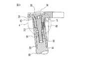
頸骨側膝補綴部材2は、頸骨基端の関節表面を置換するために、所望の関節補綴構造を形成するように互いに結合可能な別個の構成要素であるトレイ10、キール(延長部材)40およびステム80を備える。トレイ10はほぼ平坦な頂面12および底面14を備える。頂面12は、当業者には公知なように、ポリエチレン製当接面のような当接面(図示せず)を受容する。底面14は頸骨基端の切除端部上に載置されるように形成される。一つまたはそれ以上のフィン16が、底面14に沿って径方向に延び、底面14から下方に向かって突出する。フィン16は頸骨基端に切除された溝内に受容され、補綴部材の回転に抵抗する。フィン16はトレイの曲げ慣性モーメントを増大させることによってトレイ10の強度を高めるのに利用される。更なる安定を望む場合、トレイには、底面14から下方に延びるボス18を介して付加的構成要素のモジュール式取付具が設けられる。ボス18は、トレイ10の底面14に結合された頂端部20と、自由に突出している底端部22と、頂端部20から底端部22まで延びる軸線とを備える。ボス18の外側は外壁24により画定され、内部ボア26が頂端部20から底端部22まで延びる。外壁24は筒状当接部分28を、テーパ状当接部分30と、これら部分の間の解放された非当接部分29とを備える。整列穴32が底端部22に形成され、外壁24と内部ボア26との間で上方に向かって延びる。フィン16はボス18に接触していてもよいし、間隙34を残してボス18から短いところでとまっていてもよい。 The tibia
骨への頸骨側補綴部材の安定性を増大させるためにトレイに延長部材を取付けることができる。このような延長部材はステム、溝付きステムまたはキールの形態である。延長部材は対称であってもよいし非対称であってもよい。図示した実施形態では、骨への頸骨側補綴部材の回転安定性および曲げ安定性を高めるためにキール40がボス18と嵌合せしめられる。キール40は、間に軸線が延びる頂端部43および底端部44と、外壁(外面)46とを有する細長い本体を有する。キール40は、外壁46に沿って軸線方向に延びると共に径方向外側へ突出する少なくとも一つのフィン48を備える。また、キール40は、頂端部42から下方に向かって延びると共に筒状当接部分52とテーパ状当接部分54と端壁56とを備えるボア壁を有する第一軸線ボア50を備える。端壁56内には下方に向かって延びる整列穴58が形成される。さらに、キール40は、底端部44から上方に向かって延びると共にテーパ状側壁65を具備する第二軸線ボア64を有する。第一軸線ボア50と第二軸線ボア64との間でキー溝付き入口開口66が通じる。入口開口66は円形中央開口67と側方スロット68とを有し、突起と係合可能な部材を形成する。あるいは、入口開口66はネジ付部材と係合するようにネジ山が設けられてもよい。 An extension member can be attached to the tray to increase the stability of the tibia prosthesis member to the bone. Such extension members are in the form of stems, grooved stems or keels. The extension member may be symmetric or asymmetric. In the illustrated embodiment, the keel 40 is mated with the boss 18 to increase the rotational and bending stability of the tibia prosthesis member to the bone. The keel 40 has an elongate body having a top end 43 and a
キール40は、トレイ10とキール40との間の連結部が形成されるように、ボス18が第一軸線ボア50に受容され、ボス18のテーパ状部分30がボアのテーパ状部分54上に載置され、且つボス18の筒状部分28が圧入関係でボアの筒状部分52に受容された状態でトレイ10と係合する。テーパ状部分は構成要素同士が合わさるようにこれら構成要素を整列させるのを補助する。筒状の圧入部は構成要素を互いに繋止する。また、筒状の圧入部は液密なシールを提供し、連結部へまたは連結部から圧入部を通って物質が移動するのを防止する。図示した実施形態では、ボス18の解放部分29は、連結部の筒状部分28、52とテーパ状部分30、54との間において、ボス18と第一軸線ボア50との間に周状間隙69を形成する。トレイ10およびキール40は整列穴32、58の一方に整列ピン70を設けることによって整列せしめられる。図示した実施形態では、キール40の整列穴58は整列ピン70よりも僅かに小さく、ピン70は整列穴58に押し込まれる。トレイ10の整列穴32は整列ピン70よりも僅かに大きい。よって、これら構成部材を合わせるときに、これら構成部材はトレイ10の整列穴32が整列ピン70と係合するまで互いに載置されない。ボス18とフィン16との間に間隙34が存在する場合、キール40の頂端部42はさらに上方まで延び、図4に示したように間隙34内に嵌合せしめられる。 In the keel 40, the boss 18 is received in the first
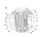
本発明の連結では圧入を用いており、このことはモールステーパ型(Morse taper-type)構成を単独で使用した場合よりも有利である。圧入は、構成要素を緊密な摩擦係合で共に摺動させることができるようにし、液密シールを作り出すと共にずれに対する強い抵抗を作り出す。テーパが典型的に嵌合部品間で線接触するのに対して、加工能力により圧入は帯状接触または面接触する。したがって、圧入は、良好なシールを提供し、物質が圧入境界を横断して移動するのを防止しやすい。さらに、圧入繋止構成は、構成要素間の精密な軸線方向の位置決めに依存せず、したがって最初の圧入係合が達成されると構成要素を所望の位置に位置決めすることができるようになる。筒状の圧入部が図示され且つ精密な加工に向いているが、本発明では摺動圧入において他の断面形状が用いられてもよい。また、連結は、組立中に構成要素を芯合わせするために提供されたテーパ状係合と、互いの上にテーパ状部分が位置したときに載置に対する能動的停止とを用いている。テーパが完全に載置されると、圧入接触とテーパ接触との間が軸線方向に離れていることにより、連結部の曲げ強度が増大せしめられる。図4に示したように、圧入部分28、52とテーパ状部分30、54とは、連結部の曲げ強度が最大となるように、できるだけ軸線方向に離されている。図示したテーパは、予測可能な載置深さにおいて、テーパの製造を容易にするために3°以上である。しかしながら、テーパは繋止強度をより増大させるために繋止用テーパであってもよい。圧入では、係合せしめられた後にも組立中に軸線方向の移動が可能であるため、連結部のテーパ状部分は圧入部が係合せしめられた後には繋止されるようにしてもよい。繋止用テーパは約1.5°〜3°である。 The connection of the present invention uses press-fitting, which is more advantageous than using a Morse taper-type configuration alone. The press fit allows the components to slide together with tight frictional engagement, creating a fluid tight seal and a strong resistance to slippage. While the taper is typically in line contact between mating parts, the press fit is in strip or surface contact depending on the processing capability. Thus, press fit provides a good seal and tends to prevent material from moving across the press fit boundary. In addition, the press-fit locking configuration does not rely on precise axial positioning between the components, thus allowing the components to be positioned in the desired position once the initial press-fit engagement is achieved. Although a cylindrical press-fit portion is illustrated and suitable for precise machining, other cross-sectional shapes may be used in the slide press-fit in the present invention. The connection also uses a tapered engagement provided to center the components during assembly and an active stop for placement when the tapered portions are positioned over each other. When the taper is completely placed, the bending strength of the connecting portion is increased due to the axial contact between the press-fit contact and the taper contact. As shown in FIG. 4, the press-
組み立てられると、トレイのフィン16とキールのフィン48は、図6に明示したように、頂部から底部まで互いに整列せしめられ、単一のフィンとして突出する。しかしながら、トレイ10とキール40とが完全に組み立てられたとき、フィン16とフィン48とが接触しないようにこれらの間には軸線方向間隙72が残る。図示した実施形態では、テーパ状部分54および繋止ピン70の上方にある筒状圧入部分52と共に第一軸線ボアが配設される。この構成およびフィン16、48の間の軸線方向空間72により、連結部の外側においてトレイ10とキール40とは接触しない。構成要素間の接触によって生成される粒子は連結部内にシールされ、連結空間内に上方へ移動することができない。芯合わせ機能および繋止機能を提供するためにテーパ状部分を筒状部分の上方に形成することは本発明の範囲内であるが、このような構成は上記と同様なシール特性を提供しない。 When assembled, the
頸骨側補綴部材の曲げ安定性をより高くするために、トレイ10およびキール40の組立体にステム80を組み合わせることができる。ステム80は頂端部84と底端部86とを有するシャフト82を備える。頂端部84はテーパ状部分88と軸線方向のネジ付きボア90とを備える。ステム80のテーパ状部分88は、キール40の第二軸線ボア64内に受容される。このテーパ状連結部は、自己繋止式テーパとして提供される。ボルト92がボス18の内部ボア26と入口開口66とを通って延び、ステム80のネジ付きボア90内にねじ込まれ、構成要素を互いに引き寄せ、保持する。ボルト92のヘッド94はトレイ10の頂面12に形成されたカウンタボア96内に配置される。 A
本発明は、組立中に直線的な付勢力を要求するモジュール式連結構成要素を組み立てるための組立工具をさらに具備する。この組立工具は、大きな組立力が必要な場合に特に適している。また、組立工具は、小さな遠隔手術空間に組立力を伝達するのが必要な場合に連結部に最小限の侵襲性でアプローチするのにも適している。図示したモジュール式インプラントの実施形態の圧入構成は、圧入構成要素間の干渉量(重なり量)に応じて453kg〜907kg(1000〜2000ポンド)の組立力が必要である。例えば、0.025mm(0.001インチ)の干渉(重なり合い)が認められると453kgが必要となり、0.051mm(0.002インチ)の干渉が認められると907kgが必要となる。同様に、構成要素が組立のために配置されたときに、組立からゆるみを取り除くために1.27mm(0.050インチ)の移動が必要とされ、構成要素を完全に係合させるために2.54mm(0.100インチ)の移動が必要とされる。 The present invention further comprises an assembly tool for assembling modular connecting components that require a linear biasing force during assembly. This assembly tool is particularly suitable when a large assembly force is required. The assembly tool is also suitable for minimally invasive approaches to connections when it is necessary to transmit assembly forces to a small telesurgical space. The press-fit configuration of the illustrated modular implant embodiment requires an assembly force of 453-907 kg (1000-2000 pounds) depending on the amount of interference between the press-fit components. For example, if interference (overlap) of 0.025 mm (0.001 inch) is recognized, 453 kg is required, and if interference of 0.051 mm (0.002 inch) is recognized, 907 kg is required. Similarly, when the component is placed for assembly, a 1.27 mm (0.050 inch) movement is required to remove the slack from the assembly and 2 to fully engage the component. A travel of .54 mm (0.100 inch) is required.
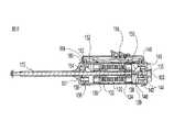
図7〜図10は、図示したモジュラー式インプラントを組み立てるために必要な力および移動を提供することができる組立工具の例示的な実施形態を示す。コンプレッサ100は、基端部101と末端部103とを有するハンドル102と、ハンドルに堅固に取付られる取付端部106と作用端部108とを有する第一シャフト部材104と、この第一シャフト部材104に対して軸線方向に移動するように第一シャフト部材104内に同軸に取付けられる第二シャフト部材110とを備える。第二シャフト部材110は、第一端部112と第二端部114とを備える。第一端部112はネジ状先端部または突起付き先端部として係合先端部116を備える。図示した実施形態は、丸い中央部分118と径方向外側に向かって延びる一対の耳状部材120とを有するT字状突起付き先端部116を具備する。突起付き先端部116は、キール40内の入口開口66とほぼ同一の形状であり、突起付き先端部116を入口開口66内に挿入し且つキール40に対して四分の一回転だけ第二シャフト部材110を回動させて耳状部材120が入口開口66の下側を越えて延び且つ把持することによりキール40に取付けられる。ハンドル102内にはリニアモータが配置され、このリニアモータは軸線方向の力を伝えるように第二シャフト部材110の第二端部114に連結される。リニアモータは、モジュール式連結構成要素を組み立てるのに必要となるまでエネルギを蓄える。モータが作動せしめられると、モータは第二シャフト部材110をハンドルに向かって移動させ、よって突起付き先端部116を第一シャフト部材104の作用端部108に向かって移動させる。 7-10 illustrate an exemplary embodiment of an assembly tool that can provide the necessary force and movement to assemble the illustrated modular implant. The
使用時には、モジュール式連結構成要素はまず軸線ボア50内に受容されるボス18と係合せしめられる。第一シャフト部材104および第二シャフト部材110は、第二シャフト部材110の突起付き先端部116が入口開口66を通って延びるまで、内部ボア26に沿って挿入せしめられる。そして、耳状部材120が入口開口66の縁部の下側で延びるように工具が回動せしめられる。この時点で、突起付き先端部116は能動的にキール40と係合し、作用端部108はカウンタボア96の底部上に載置される。モータが作動せしめられ、第二シャフト部材110は、トレイ10とキール40とを引き寄せて繋止係合させるように引っ張られる。そして、工具100は、耳状部材120が再び入口開口66と整列するまで回動せしめられ、工具100が引き出される。 In use, the modular coupling component is first engaged with the boss 18 received in the
工具100を作動させるために直線運動を発生させるのに様々な発動機構が提供され得る。例えば、回転運動から直線運動への変換器に連結された電気回転モータまたは液圧回転モータ、液圧直線モータ、バネ機構等が含まれる。図示した実施形態は、入れ子コア132によって拘束された二十のベルビルワッシャ130を具備する直線バネ式発動機を示す。ワッシャ130のスタックの両端に第一運動ブロック134および第二運動ブロック136が当接する。他の制限が無ければ、第一運動ブロック134、第二運動ブロック136およびワッシャ130はハンドル102内で軸線方向に自由に移動することができる。第二シャフト部材110は、軸線方向に摺動するように第二運動ブロック136および入れ子コア132を通って延びる。第二シャフト部材110の第二端部114は第二シャフト部材110が第一運動ブロック134と共に移動するように第一運動ブロック134に連結せしめられる。軸線方向の開口137が、第一運動ブロック134と整列してハンドル102の外側から内側まで連通する。開口137は、第一運動ブロック134を押し付けて機構を圧縮するために、外部プレスに取付けられたラムをハンドル102内に挿入することができるようにする。 Various trigger mechanisms can be provided to generate a linear motion to operate the
一対のリンクを具備するリンク機構がハンドル102の各端部に配置され、二つの運動ブロックを能動的に捕獲および解放する。末端側リンク機構は互いに対して回動するように共にピン139で留められた第一リンク138と第二リンク140とを具備する。第一リンク138は第一運動ブロック134に対して回動するように上記ピン139側とは反対側の端部で第一運動ブロック134にピン留めされる。第二リンク140は、ハンドル102に対して回動するように上記ピン139側とは反対側の端部でハンドル102の末端部103にピン135で留められる。リンク機構は、第二リンク140から突出した舌状部142がハンドルのピン144と接触することによって、その揺動軸線に沿った特異点で、または上死点で整列するのが防止される。舌状部142およびピン144は特異点に到達する2°前にリンク機構の反時計回りの回動を停止させる。第一繋止ピン146はハンドル102の側方にあるボア148内で摺動し、リンク機構が時計回りに回動するのを解放可能にブロックするように第二リンク140上のカム150と係合する。この位置でリンク機構が浅い角度にあることにより、運動ブロックに加わる軸線方向の大きな力は繋止ピン146に対する小さな力となって伝えられる。一対のリンク152、154を具備する同様なリンク機構がハウジングの基端部101および第二運動ブロック136にピン留めされる。このリンク機構は同様に舌状部156およびピン158によって回動が制限され、ボア164内で摺動する第二繋止ピン162によって解放可能にブロックされる。 A link mechanism comprising a pair of links is disposed at each end of the
二つの繋止ピン146、162の順次的作動(sequential operation)を容易にするためにトリガ機構170が設けられる。トリガハウジング172がハンドル102上に取付けられ、トリガハウジング172はトリガ機構の他の部品を保持する。第一レバー174がハウジング172内で回動するようにピン178で留められ、第一レバー174は入力端部173と出力端部175とを備える。出力端部175はヨーク182を介して第一繋止ピン146に連結され、ヨーク182は第一繋止ピン146上に形成されたボール状端部184を囲う。第一レバー174の入力端部173はリーフスプリング186によって上方へと付勢され、これにより第一繋止ピン146がカム150と係合するように下方へ付勢される。第一レバー用揺動ピン178は出力端部175に近く、これにより入力長さと出力長さとの割合に比例して機械的利点が得られる。したがって、入力端部173に加えられた力は増強せしめられ、よって繋止ピン146の操作が容易になる。同様に、第二レバー176がハウジング172内で回動するようにピン180で留められ、第二レバー176は入力端部187と出力端部188とを備える。出力端部188はヨーク190を介して第二繋止ピン162に連結され、ヨーク190は第二繋止ピン162に形成されたボール状端部192を囲う。第二レバー176の入力端部187はリーフスプリング194によって上方へと付勢され、これにより第二繋止ピン162がカム160と係合するように下方へと付勢される。トリガハウジング172内で回動するようにトリガ196がピン198で留められ、二つのレバー174、176の入力端部173、187上に当接する。 A
トリガ196は第一レバー174の入力端部173と係合するように下方へと突出する第一接触部200を備える。また、トリガ196は、第二レバー176の入力端部187と係合するように下方へと突出する第二接触部202を備える。第二接触部202は、第一レバー174が完全に作動せしめられるまで第二レバーを作動させることのないように、第一接触部200から離間される。 The
使用時には、組立工具100はその末端部が下になるように保持され、重力により第二運動ブロック136が軸線方向下方へ機構の中心に向かって移動せしめられる。第二運動ブロック136が移動すると、第二繋止ピン162がカム160上に載置された状態で基端側リンク機構が時計回りに回動せしめられる。リンク機構が限界まで直線状にせしめられると、繋止ピン162はカム160の端部上でスリップし、第二運動ブロック136を繋止する位置にスナップ留めされる。第一運動ブロック134は、外力で軸線方向に機構の中心に向かって押し付けられ、ワッシャ130を圧縮する。第一運動ブロック134が移動すると、第一繋止ピン146の端部がカム150上に載置された状態で末端側リンク機構が反時計回りに回動せしめられる。リンク機構が限界まで直線状にせしめられると、ピン146はカム150の端部上でスリップせしめられ、第一運動ブロック134を繋止する位置にスナップ留めされる。このように予め準備された組立工具は、モジュール式連結構成要素を組み立てるために使用される状態にある。組立工具100は、インプラント構成要素と係合せしめられる。そして、組立工具を作動させるためにトリガ196が押される。トリガ196はその揺動ピン198回りで回動すると、第一接触部200が第一レバー174の入力端部173を押し付け、出力端部175が第一繋止ピン146を引っ張り、末端側リンク機構を解放する。末端側リンク機構は、時計回りに回動し、これにより第一運動ブロック134が末端方向にはねるように移動する。第二シャフト部材110は第一運動ブロック134と共に移動し、モジュール式構成要素を共に引き寄せる。組立工具のバネの作用により圧入連結部がスナップ式に係合せしめられる。第一運動ブロック134が解放されても、残りのバネ張力はまだ圧入連結部を締め付けるのに必要な最小値を超えている。このことは、連結部が完全に締め付けられることを確実にするが、連結構成要素から工具100を取り外すのを困難にする。そこで、トリガを引き続き押し続けると、第二接触部202が第二レバー176の入力端部187を押し、第二繋止ピン162を引っ張る。これにより、第二運動ブロック136が基端方向へはねるように移動し、残りのバネの張力が解放される。そして、組立工具100は、連結構成要素から解放される。二段階式のトリガの解放は迅速に行われ、順次的な個別の解放を行うのにユーザには単にトリガを完全に押し付けることが必要とされる。 In use, the
臨床上の使用では、膝関節に切り口が入れられる。本発明では侵襲的な外科的アプローチを最小限にするために、膝蓋上嚢の軟組織を傷つけることを避けつつ関節面を曝すために膝関節の中間側または横側の一方に切り口が入れられる。次に、切り口を介して骨切除器具が導入され、頸骨基端側の準備を整え、キールを受容するための凹部を形成する。頸骨上に安定した平坦な面を設けるのに必要な最小限の骨のみを除去するのが理想的である。図示したモジュール式頸骨構成要素は薄型である。このように薄型でモジュール化されていることにより、切り口を非常に小さいものとすることができ、個々の構成要素が通過するのに十分な大きさのみしか必要ない。本研究者は、全高が18mm以下のトレイ構成要素であれば、このように侵襲性の低い外科的な切り口を介して挿入することができ、骨の除去量を最小限にして頸骨と係合させることができることを発見した。本発明のキール構成要素は、トレイの大きな頂面がないため準備された結合空間内へと運ばれる。同様に、構成要素が薄型でモジュール化されていることは、膝蓋を大腿骨に対して解剖学的向きのままにすることができ、関節に受ける外傷をさらに減少させ且つ処置からの回復および結果を補助する。その後、トレイが切り口を介して運ばれ、キールに係合せしめられる。トレイおよびキールに組立器具を係合させ、構成要素を共に引き寄せることで、圧入部を係合させ、モジュール式連結部のテーパ状部分を載置させることが達成される。 In clinical use, a cut is made in the knee joint. In the present invention, in order to minimize the invasive surgical approach, an incision is made in one of the medial or lateral sides of the knee joint to expose the joint surface while avoiding damaging the soft tissue of the suprapatellar sac. Next, a bone resection tool is introduced through the incision to prepare the proximal tibia and form a recess for receiving the keel. Ideally, only the minimum bone needed to provide a stable flat surface on the tibia is removed. The illustrated modular tibial component is thin. By being thin and modular in this way, the cuts can be made very small and need only be large enough for the individual components to pass through. The researchers can insert a tray component with an overall height of 18 mm or less through such a less invasive surgical incision and engage the tibia with minimal bone removal. I found out that I can make it. The keel component of the present invention is carried into the prepared coupling space because there is no large top surface of the tray. Similarly, the low profile and modularity of the components allows the patella to remain in an anatomical orientation with respect to the femur, further reducing trauma to the joint and recovery and outcome from the procedure. To assist. The tray is then carried through the cut and engaged with the keel. By engaging the assembly tool with the tray and keel and pulling the components together, engaging the press-fit and placing the tapered portion of the modular connection is accomplished.
上述した内容は本発明の例示的な実施形態を説明したに過ぎず、これら実施形態に対して特許請求の範囲に定義された発明の精神および範囲を逸脱することなく変更を加えてもよいことは当業者には理解されるであろう。本発明の様々な特徴は、例示した頸骨用インプラントに加えて様々な骨のインプラントに適用可能である。同様に、雄/雌係合部分を示したが、雄構成要素および雌構成要素は反対でもよく、且つそれでもなお本発明の予想される範囲内にある。同様に、複数の不調和な連結形状の構成は、本発明内に維持されつつ変更される。例えば、図示した実施形態は、圧入部およびテーパ部を有する連結部を示している。本発明は、圧入部の前にテーパ部がくるように順序を逆にすることも意図するものである。 The foregoing is merely illustrative of exemplary embodiments of the invention, and modifications may be made to these embodiments without departing from the spirit and scope of the invention as defined in the claims. Will be understood by those skilled in the art. Various features of the present invention are applicable to various bone implants in addition to the illustrated tibia implants. Similarly, although male / female engaging portions are shown, the male and female components may be reversed and still be within the expected scope of the present invention. Similarly, the configuration of the plurality of incongruently connected shapes is modified while maintaining within the present invention. For example, the illustrated embodiment shows a connecting portion having a press-fit portion and a tapered portion. The present invention also contemplates reversing the order so that the tapered portion is in front of the press-fit portion.
10…トレイ
18…ボス
40…キール
50…第一軸線ボア
64…第二軸線ボア
70…整列ピン
80…ステム
92…ボルト
100…コンプレッサ
102…ハンドル
104…第一シャフト部材
110…第二シャフト部材DESCRIPTION OF
Claims (55)
Translated fromJapanese上記トレイおよび延長部材のうちの一方は外側に突出するボスを備え、該ボスは筒状部分およびテーパ状部分を備える外壁を有し、
上記トレイおよび延長部材のうちの他方は内側に延びてボア壁を形成するボアを備え、該ボア壁は筒状部分とテーパ状部分とを備え、
上記延長部材は、上記ボスが上記ボア内に受容された状態で上記トレイと取り外し可能に係合することができ、上記ボスのテーパ状部分が上記ボアのテーパ状部分上に載置されると共に上記ボスの筒状部分が圧入状態で上記ボアの筒状部分に受容されて、上記トレイと延長部材との間の連結部を形成する膝補綴部材の頸骨用構成要素。A tray having a generally flat top and bottom surface and an extension member forming an elongated body having a top and bottom end;
One of the tray and the extension member includes a boss protruding outward, the boss having an outer wall including a cylindrical portion and a tapered portion;
The other of the tray and the extension member includes a bore that extends inward to form a bore wall, the bore wall including a cylindrical portion and a tapered portion,
The extension member can be removably engaged with the tray with the boss received in the bore, and the tapered portion of the boss is mounted on the tapered portion of the bore. A tibial component of a knee prosthesis member in which the tubular portion of the boss is received in the tubular portion of the bore in a press-fit state to form a connection between the tray and the extension member.
頂端部と底端部と該頂端部から底端部まで延びる軸線とを有し、且つ上記第一構成要素の底面に取り外し可能に取付けられる第二構成要素とを具備し、
上記第一構成要素および第二構成要素のうちの一方は外壁を有する雄連結要素を備え、該外壁は第一形状である第一載置部分と第二形状である第二載置部分とを備え、
上記第一構成要素および第二構成要素のうちの他方は内壁を有する雌連結要素を備え、該内壁は、上記雄第一載置部分の形状と一致する第一形状である第一載置部分と、上記雄第二載置部分の形状と一致する第二形状である第二載置部分とを備え、第一載置部分の形状と第二載置部分の形状とは一致しておらず、上記第二構成要素は上記雄第一載置部分および雄第二載置部分が雌第一載置部分および雌第二載置部分と緊密状態となるように解放可能に上記第一構成要素に連結せしめられる骨関節用インプラント。A first component having a top surface and a bottom surface;
A second component having a top end, a bottom end, an axis extending from the top end to the bottom end, and removably attached to the bottom surface of the first component;
One of the first component and the second component includes a male coupling element having an outer wall, and the outer wall includes a first mounting portion having a first shape and a second mounting portion having a second shape. Prepared,
The other of the first component and the second component includes a female connecting element having an inner wall, and the inner wall has a first shape that matches the shape of the male first component. And a second mounting portion that is a second shape that matches the shape of the male second mounting portion, and the shape of the first mounting portion does not match the shape of the second mounting portion. The second component is releasable so that the male first mounting portion and the male second mounting portion are in close contact with the female first mounting portion and the female second mounting portion. Bone and joint implants to be connected to
頂端部と、底端部と、上記トレイの軸線にほぼ平行に該頂端部から該底端部まで延びる軸線とを有するキールであって、外面を形成すると共に上記トレイの底部に取り外し可能に取付けられ、上記外面に沿って軸線方向に延びると共に径方向外側に突出する少なくとも一つのフィンをさらに具備するキールとを具備し、
上記トレイのフィンと上記キールのフィンとは、頂部から底部まで互いにほぼ軸線方向に整列し、単一のフィンとして突出しつつこれらフィンが接触しないように軸線方向に離間されている膝補綴部材の頸骨用構成要素。A tray having a top surface, a bottom surface, and an axis extending therebetween, wherein at least one fin extends radially outward along the bottom surface and protrudes downward in the axial direction;
A keel having a top end, a bottom end, and an axis extending from the top end to the bottom end substantially parallel to the axis of the tray, forming an outer surface and removably attached to the bottom of the tray A keel further comprising at least one fin extending in the axial direction along the outer surface and projecting radially outward,
The fins of the tray and the fins of the keel are substantially axially aligned from top to bottom and project as a single fin but are spaced apart axially so that they do not contact each other Components.
上端部と底端部と該上端部から該底端部まで延びる軸線とを有し、上記トレイの底部と係合可能なキールとを具備し、
上記キールと上記トレイとは、該キールとトレイとを予め定められた組立関係で整列するための回動方向整列手段を有する連結部を形成し、該回動方向整列手段は該回動方向整列手段から上記連結部の外部に物質が移動することを防止するように上記連結部内にシールされる膝補綴部材の頸骨用構成要素。A tray having a top surface and a bottom surface;
A keel having an upper end portion, a bottom end portion, and an axis extending from the upper end portion to the bottom end portion, and capable of engaging with the bottom portion of the tray;
The keel and the tray form a connecting portion having a rotation direction alignment means for aligning the keel and the tray in a predetermined assembly relationship, and the rotation direction alignment means is the rotation direction alignment. A tibial component of a knee prosthesis member sealed within the connecting portion to prevent movement of material from the means to the exterior of the connecting portion.
第一モジュール式連結構成要素および第二モジュール式連結構成要素とそれぞれ連結可能な第一工具要素および第二工具要素とを具備し、上記第一モジュール式連結構成要素と上記第二モジュール式連結構成要素とを引き寄せて載置状態となるように、当該組立工具を作動させて該第一工具要素と第二工具要素とを互いに対して付勢することができるようにエネルギを蓄える組立工具。In an assembly tool for assembling the first modular connecting component and the second modular connecting component,
A first tool element and a second tool element connectable to the first modular connection element and the second modular connection element, respectively, the first modular connection element and the second modular connection structure; An assembly tool that stores energy so that the first tool element and the second tool element can be biased relative to each other by actuating the assembly tool so that the elements are drawn and placed.
上記バネの第一端部に取付けられる第一リンク機構と、
上記バネの第二端部に取付けられる第二リンク機構とをさらに具備し、
上記第一リンク機構は、上記バネの第一端部を解放し、上記蓄えられた付勢エネルギの第一部分を解放して第一工具要素と第二工具要素とを互いに対して移動させるように作動可能であり、上記第二リンク機構は、上記バネの第二の端部を解放して上記蓄えられた付勢エネルギの第二部分を解放するように作動可能である請求項33に記載の組立工具。A compressible spring for storing energizing energy;
A first link mechanism attached to the first end of the spring;
A second link mechanism attached to the second end of the spring;
The first link mechanism releases the first end of the spring and releases the first portion of the stored biasing energy to move the first tool element and the second tool element relative to each other. 34. The method of claim 33, operable and wherein the second linkage is operable to release a second end of the spring to release a second portion of the stored biased energy. Assembly tool.
ハンドルと、
軸線方向に移動するようにハンドルに取付けられ且つ軸線方向の力を伝達するように第一モジュール式連結構成要素と係合可能な第一シャフト部材と、
上記ハンドルに繋止され且つ軸線方向の力を伝達するように第二モジュール式連結構成要素と係合可能な第二シャフト部材と、
上記第一シャフト部材に軸線方向の力を加えて上記連結構成要素を移動させるように上記第一部材と係合する発動機とを具備し、当該組立工具が該発動機を駆動するためのエネルギを蓄える組立工具。An assembly tool for assembling the first modular connecting component and the second modular connecting component,
A handle,
A first shaft member attached to the handle for axial movement and engageable with a first modular coupling component to transmit axial force;
A second shaft member secured to the handle and engageable with a second modular coupling component to transmit axial force;
An engine that engages the first member so as to move the connecting component by applying an axial force to the first shaft member, and energy for the assembly tool to drive the engine. Assembly tool to store.
対応する第一係合部分および第二係合部分を有する第一モジュール式連結構成要素および第二モジュール式連結構成要素を提供する工程と、
第一工具要素と第二工具要素とを有する工具であって、第一工具要素と第二工具要素とを互いに対して付勢することができる蓄えられたエネルギを含む工具を提供する工程と、
上記第一係合部分と第二係合部分とを整列させる工程と、
上記第一工具要素および第二工具要素を上記第一モジュール式連結構成要素および第二モジュール式連結構成要素に係合させ、上記工具を作動させて、上記蓄えられたエネルギを解放して、上記第一工具要素および第二工具要素を付勢し、第一モジュール式連結構成要素と第二モジュール式連結構成要素とを引き寄せる工程とを具備する組立方法。An assembly method for assembling modular components,
Providing a first modular coupling component and a second modular coupling component having corresponding first and second engaging portions;
Providing a tool having a first tool element and a second tool element, the tool including stored energy capable of biasing the first tool element and the second tool element relative to each other;
Aligning the first engagement portion and the second engagement portion;
Engaging the first tool element and the second tool element with the first modular connection element and the second modular connection element, operating the tool to release the stored energy, and An assembly method comprising: urging the first tool element and the second tool element to draw the first modular connecting component and the second modular connecting component together.
別個のモジュール式の頸骨用トレイ構成要素とキール構成要素とを提供する工程と、
膝関節に切り口を形成する工程と、
上記構成要素を受容するように頸骨を準備する工程と、
上記キール構成要素を上記切り口を介して挿入し且つ準備された頸骨にキール構成要素を載置する工程と、
上記トレイ構成要素を上記切り口を介して挿入し且つ上記キール構成要素にトレイ構成要素を本来の場所に組み立てる工程と、
上記切り口を閉じる工程とを具備する方法。A method of implanting a modular tibial component into a knee, comprising:
Providing separate modular tibial tray components and keel components;
Forming a cut in the knee joint;
Preparing the tibia to receive the components;
Inserting the keel component through the incision and placing the keel component on the prepared tibia;
Inserting the tray component through the cut and assembling the tray component into place in the keel component;
Closing the cut end.
上記第一工具要素および上記第二工具要素を頸骨トレイ構成要素およびキール構成要素と係合させ、上記工具を作動させて蓄えられたエネルギを解放し、第一工具要素および第二工具要素を付勢し、最終的な載置係合へと上記トレイ構成要素およびキール構成要素を引き寄せる工程とをさらに具備する請求項51に記載の方法。Providing a tool having a first tool element and a second tool element, the tool including stored energy capable of biasing the first rear element and the second tool element relative to each other;
The first tool element and the second tool element are engaged with the tibial tray component and the keel component to operate the tool to release the stored energy and to attach the first tool element and the second tool element. 52. The method of claim 51, further comprising: forcing and drawing the tray component and keel component to final mounting engagement.
Applications Claiming Priority (2)
| Application Number | Priority Date | Filing Date | Title |
|---|---|---|---|
| US10/369331 | 2003-02-18 | ||
| US10/369,331US7182786B2 (en) | 2002-04-25 | 2003-02-18 | Modular bone implant, tool, and method |
Publications (3)
| Publication Number | Publication Date |
|---|---|
| JP2004249105Atrue JP2004249105A (en) | 2004-09-09 |
| JP2004249105A5 JP2004249105A5 (en) | 2007-04-05 |
| JP4704692B2 JP4704692B2 (en) | 2011-06-15 |
Family
ID=32736424
Family Applications (1)
| Application Number | Title | Priority Date | Filing Date |
|---|---|---|---|
| JP2004041741AExpired - Fee RelatedJP4704692B2 (en) | 2003-02-18 | 2004-02-18 | Tibial component of knee prosthesis, assembly tool thereof, and method of use thereof |
Country Status (7)
| Country | Link |
|---|---|
| US (3) | US7182786B2 (en) |
| EP (1) | EP1449500B1 (en) |
| JP (1) | JP4704692B2 (en) |
| AU (1) | AU2004200394B2 (en) |
| CA (1) | CA2455377C (en) |
| DE (1) | DE602004007050T2 (en) |
| ES (1) | ES2287649T3 (en) |
Cited By (2)
| Publication number | Priority date | Publication date | Assignee | Title |
|---|---|---|---|---|
| JP2013517911A (en)* | 2010-01-29 | 2013-05-20 | スミス アンド ネフュー インコーポレーテッド | Cruciate ligament-preserving artificial knee joint |
| JP2014180559A (en)* | 2013-03-15 | 2014-09-29 | Depuy (Ireland) | Instruments for use in disassembling implants |
Families Citing this family (85)
| Publication number | Priority date | Publication date | Assignee | Title |
|---|---|---|---|---|
| US20020120340A1 (en)* | 2001-02-23 | 2002-08-29 | Metzger Robert G. | Knee joint prosthesis |
| US7497874B1 (en) | 2001-02-23 | 2009-03-03 | Biomet Manufacturing Corp. | Knee joint prosthesis |
| US20040162619A1 (en)* | 2001-08-27 | 2004-08-19 | Zimmer Technology, Inc. | Tibial augments for use with knee joint prostheses, method of implanting the tibial augment, and associated tools |
| US7892288B2 (en) | 2001-08-27 | 2011-02-22 | Zimmer Technology, Inc. | Femoral augments for use with knee joint prosthesis |
| US20030065397A1 (en) | 2001-08-27 | 2003-04-03 | Hanssen Arlen D. | Prosthetic implant support structure |
| EP2359775B1 (en) | 2002-02-20 | 2012-12-26 | Zimmer, Inc. | Knee arthroplasty prosthesis |
| US7182786B2 (en) | 2002-04-25 | 2007-02-27 | Zimmer Technology, Inc. | Modular bone implant, tool, and method |
| US7799086B2 (en)* | 2002-04-25 | 2010-09-21 | Zimmer Technology, Inc. | Modular bone implant, tools, and method |
| US7615081B2 (en) | 2002-05-24 | 2009-11-10 | Zimmer, Inc. | Femoral components for knee arthroplasty |
| US20040102852A1 (en)* | 2002-11-22 | 2004-05-27 | Johnson Erin M. | Modular knee prosthesis |
| US7153326B1 (en)* | 2003-06-19 | 2006-12-26 | Biomet Manufacturing Corp. | Method and apparatus for use of an offset stem connection |
| US6843274B1 (en) | 2003-06-25 | 2005-01-18 | Air Systems International, Inc. | Electrically conductive confined space ventilator conduit formed of conductive polymer, electrical grounding circuit for ventilation system using same, and methods of using and forming same |
| US7727281B2 (en)* | 2003-12-08 | 2010-06-01 | Ortho Development Corporation | Modular femoral knee stem extender |
| US7867236B2 (en) | 2003-12-30 | 2011-01-11 | Zimmer, Inc. | Instruments and methods for preparing a joint articulation surface for an implant |
| US7935120B2 (en)* | 2004-04-30 | 2011-05-03 | Zimmer Technology, Inc. | Posterior femur rough cut guide for minimally invasive knee arthroplasty |
| US8852195B2 (en) | 2004-07-09 | 2014-10-07 | Zimmer, Inc. | Guide templates for surgical implants and related methods |
| US20060142869A1 (en)* | 2004-12-23 | 2006-06-29 | Gross Thomas P | Knee prosthesis |
| US20060200158A1 (en)* | 2005-01-29 | 2006-09-07 | Farling Toby N | Apparatuses and methods for arthroplastic surgery |
| US7998217B1 (en) | 2005-02-02 | 2011-08-16 | Biomet Manufacturing Corp. | Modular offset stem implants |
| US20060247664A1 (en)* | 2005-03-08 | 2006-11-02 | California Institute Of Technology | Micromachined tissue anchors for securing implants without sutures |
| JP4852596B2 (en)* | 2005-03-14 | 2012-01-11 | インボーン テクノロジーズ, インコーポレイテッド | Ankle replacement prosthesis |
| US7357817B2 (en)* | 2005-05-19 | 2008-04-15 | Howmedica Osteonics Corp. | Modular keel tibial component |
| US7695519B2 (en)* | 2005-07-08 | 2010-04-13 | Howmedica Osteonics Corp. | Modular tibial baseplate |
| EP1787603A1 (en) | 2005-11-18 | 2007-05-23 | Zimmer GmbH | Basis-platform for an artificial joint |
| US7766969B2 (en)* | 2005-12-05 | 2010-08-03 | Zimmer, Inc. | Modular progressive implant for a joint articulation surface |
| US9241800B2 (en)* | 2005-12-21 | 2016-01-26 | Orthopaedic International Inc. | Tibial component with a conversion module for a knee implant |
| US7771484B2 (en)* | 2006-02-28 | 2010-08-10 | Howmedica Osteonics Corp. | Modular tibial implant |
| CA2648444C (en)* | 2006-04-04 | 2014-03-18 | Smith & Nephew, Inc. | Trial coupler systems and methods |
| US7842093B2 (en) | 2006-07-18 | 2010-11-30 | Biomet Manufacturing Corp. | Method and apparatus for a knee implant |
| US7691150B2 (en)* | 2006-12-15 | 2010-04-06 | Zimmer Technology, Inc. | Modular plate and keel provisionals |
| US8328873B2 (en) | 2007-01-10 | 2012-12-11 | Biomet Manufacturing Corp. | Knee joint prosthesis system and method for implantation |
| JP5448842B2 (en) | 2007-01-10 | 2014-03-19 | バイオメト マニファクチャリング コーポレイション | Knee joint prosthesis system and implantation method |
| US8163028B2 (en) | 2007-01-10 | 2012-04-24 | Biomet Manufacturing Corp. | Knee joint prosthesis system and method for implantation |
| US8187280B2 (en) | 2007-10-10 | 2012-05-29 | Biomet Manufacturing Corp. | Knee joint prosthesis system and method for implantation |
| US8562616B2 (en) | 2007-10-10 | 2013-10-22 | Biomet Manufacturing, Llc | Knee joint prosthesis system and method for implantation |
| US20080255574A1 (en)* | 2007-04-13 | 2008-10-16 | Zimmer Technology, Inc. | Instrument for insertion of prosthetic components |
| US8177849B2 (en) | 2007-05-07 | 2012-05-15 | Zimmer, Inc. | Methods and apparatuses for attaching tissue to orthopaedic implants |
| US20110087295A1 (en)* | 2009-10-12 | 2011-04-14 | University Of Utah | Bone fixation systems |
| US8657820B2 (en) | 2009-10-12 | 2014-02-25 | Tornier, Inc. | Bone plate and keel systems |
| US8439593B2 (en)* | 2009-11-10 | 2013-05-14 | Imds Corporation | Quarter turn locking mechanism |
| US8444699B2 (en)* | 2010-02-18 | 2013-05-21 | Biomet Manufacturing Corp. | Method and apparatus for augmenting bone defects |
| US8679130B2 (en) | 2010-03-05 | 2014-03-25 | Biomet Manufacturing, Llc | Guide assembly for lateral implants and associated methods |
| US8221432B2 (en) | 2010-03-05 | 2012-07-17 | Biomet Manufacturing Corp. | Method and apparatus for implanting a modular femoral hip |
| US8419743B2 (en) | 2010-03-05 | 2013-04-16 | Biomet Manufacturing Corp. | Assembly tool for modular implants and associated method |
| US8333807B2 (en)* | 2010-03-05 | 2012-12-18 | Biomet Manufacturing Corp. | Method and apparatus for trialing and implanting a modular femoral hip |
| US8529569B2 (en) | 2010-03-05 | 2013-09-10 | Biomet Manufacturing, Llc | Method and apparatus for preparing a proximal femur |
| US8460393B2 (en) | 2010-03-05 | 2013-06-11 | Biomet Manufacturing Corp. | Modular lateral hip augments |
| US8932364B2 (en)* | 2010-07-14 | 2015-01-13 | Howmedica Osteonics Corp. | Prosthetic knee void filers with splined fixation |
| US8728167B2 (en) | 2011-01-10 | 2014-05-20 | Howmedica Osteonics Corp. | Bicruciate retaining tibial baseplate design and method of implantation |
| US9668871B2 (en) | 2011-12-29 | 2017-06-06 | Mako Surgical Corp. | Cruciate-retaining tibial prosthesis |
| US8911501B2 (en) | 2011-12-29 | 2014-12-16 | Mako Surgical Corp. | Cruciate-retaining tibial prosthesis |
| CN106667543B (en) | 2012-03-30 | 2020-09-01 | 德普伊新特斯产品有限责任公司 | Stemless humeral component and associated surgical instrument and method |
| US9345578B2 (en) | 2013-02-22 | 2016-05-24 | Stryker Corporation | Bicruciate retaining tibial implant system |
| USD730522S1 (en)* | 2013-03-11 | 2015-05-26 | Catalyst Orthopaedics Llc | Implant |
| US9814588B2 (en) | 2015-08-10 | 2017-11-14 | Catalyst Orthoscience Inc. | Glenoid arthroplasty with multi-directional fixation |
| US20170319348A1 (en) | 2015-08-10 | 2017-11-09 | Catalyst Orthoscience Inc. | Arthroplasty prostheses with multi-axis fixation |
| US11007063B2 (en) | 2013-03-11 | 2021-05-18 | Catalyst Orthoscience Inc. | Offset reamers |
| US9814471B2 (en) | 2013-03-11 | 2017-11-14 | Catalyst Orthoscience Inc. | Glenoid arthroplasty and offset reamers |
| US10973646B2 (en) | 2013-03-11 | 2021-04-13 | Catalyst Orthoscience Inc. | Stabilized drill guide |
| US9949839B2 (en) | 2013-03-13 | 2018-04-24 | Wright Medical Technology, Inc. | Revision implant augments, systems, and methods |
| US9289306B2 (en) | 2013-03-15 | 2016-03-22 | Catalyst Orthopaedics Llc | Humeral arthroplasty |
| USD735338S1 (en) | 2013-10-31 | 2015-07-28 | Catalyst Orthopaedics Llc | Humeral component for shoulder arthroplasty |
| AU2015263772A1 (en)* | 2014-05-23 | 2017-01-12 | Robert Lye | Integrated skeletal implant and its method of surgical implantation |
| CA2889245C (en)* | 2014-11-07 | 2018-05-01 | Kian-Ming Wong | Talar dome fixation stem |
| DE102015209520B3 (en)* | 2015-05-22 | 2016-10-27 | Peter Brehm Holding Gmbh & Co. Kg | Modular stem endoprostheses |
| KR102603509B1 (en)* | 2015-08-27 | 2023-11-16 | 힙 이노베이션 테크놀러지 엘엘씨 | Surgical trays, instruments and methods for removing components of a hip replacement prosthesis |
| EP3355834B1 (en)* | 2015-09-29 | 2023-01-04 | Zimmer, Inc. | Tibial prosthesis for tibia with varus resection |
| US10182917B2 (en) | 2016-04-11 | 2019-01-22 | Arthrex, Inc. | Components for artificial joints |
| US9907655B2 (en) | 2016-06-17 | 2018-03-06 | Arthrex, Inc. | Components for artificial joints |
| US10231840B2 (en) | 2016-07-27 | 2019-03-19 | Howmedica Osteonics Corp. | Low profile tibial baseplate with fixation members |
| US10136998B2 (en) | 2016-08-30 | 2018-11-27 | Wright Medical Technology, Inc. | Revision total ankle implants |
| CA3051099C (en) | 2017-01-20 | 2022-07-12 | Biomet Manufacturing, Llc | Modular augment component |
| US11406502B2 (en) | 2017-03-02 | 2022-08-09 | Optimotion Implants LLC | Orthopedic implants and methods |
| US10905436B2 (en) | 2017-03-02 | 2021-02-02 | Optimotion Implants, Llc | Knee arthroplasty systems and methods |
| US12083027B2 (en) | 2017-03-02 | 2024-09-10 | Optimotion Implants LLC | Universal femoral trial system and methods |
| AU2020207869A1 (en) | 2019-08-01 | 2021-02-18 | Howmedica Osteonics Corp. | Hybrid metal-backed glenoid component |
| US11565021B1 (en) | 2019-08-12 | 2023-01-31 | Ortho Development Corporation | Composite structure porous implant for replacing bone stock |
| USD901013S1 (en) | 2019-08-12 | 2020-11-03 | Ortho Development Corporation | Porous implant |
| USD901014S1 (en) | 2019-08-12 | 2020-11-03 | Ortho Development Corporation | Porous implant |
| USD901012S1 (en) | 2019-08-12 | 2020-11-03 | Ortho Development Corporation | Porous implant |
| US12434302B2 (en) | 2019-11-25 | 2025-10-07 | Ortho Development Corporation | Method for manufacturing porous structures using additive manufacturing |
| US11498124B1 (en) | 2019-11-25 | 2022-11-15 | Ortho Development Corporation | Method for sintering porous structures from powder using additive manufacturing |
| ES2958860T3 (en)* | 2019-12-16 | 2024-02-15 | Link Waldemar Gmbh Co | Humeral implant component |
| AU2021204625A1 (en) | 2020-07-06 | 2022-01-20 | Howmedica Osteonics Corp. | Anatomic implant for joints |
| CN113876473B (en)* | 2021-08-31 | 2022-08-23 | 浙江大学 | External pin nailing device for elbow joint prosthesis pin shaft and working method of external pin nailing device |
Citations (9)
| Publication number | Priority date | Publication date | Assignee | Title |
|---|---|---|---|---|
| JPH05269161A (en)* | 1992-01-21 | 1993-10-19 | Howmedica Internatl Inc | Shank element for knee exchanging prosthesis |
| JPH10513079A (en)* | 1995-01-31 | 1998-12-15 | スミス アンド ネフュー インコーポレーテッド | Tibial prosthesis |
| JPH11309162A (en)* | 1998-03-30 | 1999-11-09 | Johnson & Johnson Professional Inc | Medical clamping device and modular artificial joint device |
| JP2000051252A (en)* | 1998-07-08 | 2000-02-22 | Johnson & Johnson Professional Inc | Back-stabilized rotatable and movable joint prosthesis |
| JP2001087292A (en)* | 1999-09-27 | 2001-04-03 | Kobe Steel Ltd | Tibia tray |
| FR2799115A1 (en)* | 1999-10-01 | 2001-04-06 | Jean Claude Bouvet | Modular shank for hip prosthesis comprises medullary pin with cylindrical surface for thrust member, stops and support |
| US6214052B1 (en)* | 1999-01-19 | 2001-04-10 | Sulzer Orthopedics Inc. | Tibial component with a reversible, adjustable stem |
| WO2002007647A2 (en)* | 2000-07-20 | 2002-01-31 | Depuy Orthopaedics, Inc. | Modular connection for orthopedic component |
| JP2002315757A (en)* | 1996-05-28 | 2002-10-29 | Howmedica Internatl S De Rl | Tibial element of artificial knee for replacement |
Family Cites Families (161)
| Publication number | Priority date | Publication date | Assignee | Title |
|---|---|---|---|---|
| US2682265A (en) | 1951-12-28 | 1954-06-29 | Marie B Collison | Trochanteric plate and artificial femoral head |
| US2785673A (en) | 1952-05-06 | 1957-03-19 | Anderson Roger | Femoral prosthesis |
| US2725878A (en)* | 1954-09-20 | 1955-12-06 | Union Broach Co Inc | Surgical mallet structure |
| US3943576A (en) | 1971-10-14 | 1976-03-16 | Sivash Konstantin Mitrofanovic | Artificial hip joint made from two different surgical alloys |
| US3848272A (en) | 1972-01-13 | 1974-11-19 | United States Surgical Corp | Artificial hip joint |
| SU428623A1 (en) | 1972-05-04 | 1976-07-05 | Саратовский государственный медицинский институт | Collapsible artificial hip joint |
| SU440014A1 (en) | 1972-05-04 | 1978-08-05 | Саратовский государственный медицинский институт | Endoprosthesis of proximal end of thighbone |
| AT337885B (en) | 1973-04-12 | 1977-07-25 | Feldmuehle Anlagen Prod | IMPLANTABLE ARTIFICIAL JOINT REPLACEMENT |
| DE2340546A1 (en) | 1973-08-10 | 1975-02-27 | Pfaudler Werke Ag | METALLIC IMPLANT AND PROCEDURE FOR ITS MANUFACTURING |
| US3906550A (en) | 1973-12-27 | 1975-09-23 | William Rostoker | Prosthetic device having a porous fiber metal structure |
| JPS5223514B2 (en) | 1974-09-25 | 1977-06-24 | ||
| US4051559A (en) | 1974-12-27 | 1977-10-04 | Mahay & Cie | Total prosthesis of the hip |
| US4086701A (en) | 1975-04-07 | 1978-05-02 | Kyoto Ceramic Kabushiki Kaisha | Device for implanting an artificial endosseous element of ceramics and an implant method for use of the same |
| US4259072A (en) | 1977-04-04 | 1981-03-31 | Kyoto Ceramic Co., Ltd. | Ceramic endosseous implant |
| DE2734249A1 (en) | 1977-07-29 | 1979-02-08 | Bayer Ag | THIGH NECK PROSTHESIS |
| IE50750B1 (en) | 1980-03-11 | 1986-07-09 | Howmedica | A set for assembly into a modular prosthesis |
| US4304011A (en) | 1980-08-25 | 1981-12-08 | Whelan Iii Edward J | Semi-constrained metacarpophalangeal prosthesis |
| DE3205577C2 (en) | 1981-02-23 | 1989-11-02 | Inc. Zweigniederlassung Kiel 2314 Schönkirchen Howmedica International | Endoprosthesis for femoral or tibial articular bone parts and adjacent femoral or tibial bone sections |
| EP0059070A1 (en) | 1981-02-24 | 1982-09-01 | Spencer Clark Metal Industries Limited | Steel corrosion protected members |
| EP0077868A1 (en) | 1981-10-26 | 1983-05-04 | Nunzio Godoli | Hip prosthesis as expanding femoral component |
| US4624673A (en) | 1982-01-21 | 1986-11-25 | United States Medical Corporation | Device system for dental prosthesis fixation to bone |
| CA1237553A (en) | 1982-01-21 | 1988-06-07 | Benjamin S. Meyer | Artificial joint fixation to bone and sleeve therefor |
| US4578081A (en) | 1982-02-17 | 1986-03-25 | Howmedica International, Inc. | Bone prosthesis |
| US4790854A (en) | 1982-02-17 | 1988-12-13 | Howmedica International Inc. | Bone prosthesis assembly |
| SE459844B (en) | 1983-08-12 | 1989-08-14 | Idea Ab | DEVICE FOR FIXING A LED PROTEST |
| DE3334058C2 (en) | 1983-09-21 | 1985-07-25 | Ulrich Dr.-Ing. 5600 Wuppertal Witzel | Thigh section for a hip joint prosthesis |
| US5190546A (en) | 1983-10-14 | 1993-03-02 | Raychem Corporation | Medical devices incorporating SIM alloy elements |
| DE3340767A1 (en) | 1983-11-08 | 1985-05-15 | Mecron Medizinische Produkte Gmbh, 1000 Berlin | KIT FOR A RESECTION PROSTHESIS |
| US4846839A (en) | 1984-02-09 | 1989-07-11 | Joint Medical Products Corporation | Apparatus for affixing a prosthesis to bone |
| EP0172883A1 (en) | 1984-02-09 | 1986-03-05 | JOINT MEDICAL PRODUCTS CORPORATION (a Delaware corporation) | Apparatus for affixing a prosthesis to bone |
| DE3435243C1 (en) | 1984-09-26 | 1986-03-13 | S + G Implants GmbH, 2400 Lübeck | Femoral prosthesis part of a knee joint endoprosthesis |
| FR2580926B1 (en) | 1985-04-24 | 1991-04-12 | Montagne Patrick | FEMALE PROSTHESIS WITH INDEPENDENT MODULAR COLLAR AND VARIABLE IN LENGTH AND DIRECTION FOR IMPLANTATIONS OF SINGLE FEMALE PROSTHESES OR TOTAL HIP PROSTHESES |
| US4792339A (en) | 1985-05-23 | 1988-12-20 | Laboratorium Fur Experiementelle Chirurgie, Forschungsinstitut | Self-locking stemmed component for a joint endo-prosthesis |
| DE3625520A1 (en) | 1986-03-15 | 1987-09-17 | Mecron Med Prod Gmbh | BONE IMPLANT |
| DE8611697U1 (en) | 1986-04-25 | 1986-06-19 | Mecron Medizinische Produkte Gmbh, 1000 Berlin | Kit for a stem prosthesis |
| US5344457A (en) | 1986-05-19 | 1994-09-06 | The University Of Toronto Innovations Foundation | Porous surfaced implant |
| US5314479A (en) | 1986-08-15 | 1994-05-24 | Depuy Inc. | Modular prosthesis |
| US5080685A (en) | 1986-08-15 | 1992-01-14 | Boehringer Mannheim Corporation | Modular hip prosthesis |
| EP0257359B1 (en) | 1986-08-15 | 1991-11-27 | Boehringer Mannheim Corporation | Modular hip prosthesis |
| US4822366A (en) | 1986-10-16 | 1989-04-18 | Boehringer Mannheim Corporation | Modular knee prosthesis |
| DE8703491U1 (en) | 1987-03-09 | 1987-04-23 | Waldemar Link Gmbh & Co, 2000 Hamburg | Hip prosthesis |
| DE8708500U1 (en) | 1987-06-12 | 1988-04-14 | Mecron Medizinische Produkte Gmbh, 1000 Berlin | Hip joint prosthesis with a cylindrical shaft part |
| US5194066A (en) | 1988-01-11 | 1993-03-16 | Boehringer Mannheim Corporation | Modular joint prosthesis |
| US4851007A (en) | 1988-03-18 | 1989-07-25 | Gray Frank B | Femoral component for a hip prosthesis |
| US4950298A (en) | 1988-04-08 | 1990-08-21 | Gustilo Ramon B | Modular knee joint prosthesis |
| US5108437A (en) | 1988-09-14 | 1992-04-28 | Pfizer Hospital Products Group, Inc. | Modular prosthesis |
| GB2222776B (en) | 1988-09-15 | 1992-12-02 | Mclardy Smith Peter David | A prosthesis |
| GB2225722B (en) | 1988-10-18 | 1992-09-09 | Univ London | Attachment device |
| DE3909580A1 (en) | 1988-11-24 | 1990-10-18 | Imz Fertigung Vertrieb | ENOSSAL IMPLANT WITH ELASTIC INTERMEDIATE ELEMENT AND METAL DISTANCE SLEEVE |
| CA2006152C (en) | 1988-12-27 | 1999-03-23 | John Edward Slamin | Modular knee prosthesis |
| US4936853A (en)* | 1989-01-11 | 1990-06-26 | Kirschner Medical Corporation | Modular knee prosthesis |
| US4938773A (en) | 1989-01-18 | 1990-07-03 | Strand John A | Hip joint prosthesis |
| US5108452A (en) | 1989-02-08 | 1992-04-28 | Smith & Nephew Richards Inc. | Modular hip prosthesis |
| US4995883A (en) | 1989-02-08 | 1991-02-26 | Smith & Nephew Richards Inc. | Modular hip prosthesis |
| US5058936A (en) | 1989-02-23 | 1991-10-22 | Raychem Corporation | Method of forming a mechanical |
| DE3909630A1 (en) | 1989-03-23 | 1990-09-27 | Daimler Benz Ag | Clamping tool for frictional and highly precise clamping of workpieces |
| US4985037A (en) | 1989-05-22 | 1991-01-15 | Petersen Thomas D | Universal modular prosthesis stem extension |
| US4938769A (en)* | 1989-05-31 | 1990-07-03 | Shaw James A | Modular tibial prosthesis |
| NL8901526A (en) | 1989-06-16 | 1991-01-16 | Ordev Bv | SELF-ADJUSTING PROSTHESIS CONFIRMATION. |
| US4917530A (en) | 1989-08-31 | 1990-04-17 | Boehringer Mannheim Corporation | Structural joint |
| US5201882A (en) | 1989-11-03 | 1993-04-13 | Paxson Robert D | Modular hip joint prosthesis with adjustable anteversion |
| US5002581A (en) | 1989-11-03 | 1991-03-26 | Dow Corning Wright Corporation | Modular hip joint prosthesis with adjustable anteversion |
| CA2029798C (en) | 1989-12-12 | 1994-12-13 | Michael J. Pappas | Prosthetic device with modular stem |
| US5019108A (en) | 1990-02-02 | 1991-05-28 | Bertin Kim C | Modular implant |
| US5133760A (en) | 1990-02-12 | 1992-07-28 | Alvarado Orthopedic Research, Inc. | Universal modular prosthesis stem extension |
| US5002578A (en) | 1990-05-04 | 1991-03-26 | Venus Corporation | Modular hip stem prosthesis apparatus and method |
| GB9010980D0 (en) | 1990-05-16 | 1990-07-04 | Thackray C F Ltd | Dummy device for moulding bone cavity form |
| CA2084095C (en) | 1990-06-01 | 2002-04-02 | David Clark Kelman | Metal/composite hybrid orthopedic implants |
| US5190549A (en)* | 1990-08-02 | 1993-03-02 | Exactech, Inc. | Locking surgical tool handle system |
| DE4031520A1 (en) | 1990-10-05 | 1992-04-09 | Implantcast Feinguss Gmbh | Endoprosthesis for long hollow bone - is made in two parts with joint which provides for adjusting overall length |
| DE9014542U1 (en)* | 1990-10-20 | 1991-01-03 | Howmedica GmbH, 2314 Schönkirchen | Shell element for receiving a joint endoprosthesis |
| CA2031571A1 (en) | 1990-12-05 | 1992-06-06 | The University Of British Columbia | Antibiotic loaded joint prosthesis |
| EP0495340A1 (en) | 1991-01-18 | 1992-07-22 | Gebrüder Sulzer Aktiengesellschaft | Modular construction kit for the tibial part of a knee joint prosthesis |
| US5658349A (en) | 1991-07-29 | 1997-08-19 | Joint Medical Products Corporation | Prosthetic joint system for bone replacement |
| GB9202248D0 (en) | 1992-02-03 | 1992-03-18 | Howmedica | Prosthesis for attachement without bone cement and method of attaching |
| US5342366A (en) | 1992-02-19 | 1994-08-30 | Biomet, Inc. | Surgical instruments for hip revision |
| US5176684A (en) | 1992-02-20 | 1993-01-05 | Dow Corning Wright | Modular shaping and trial reduction guide for implantation of posterior-stabilized femoral prosthesis and method of using same |
| US5580247A (en) | 1992-08-04 | 1996-12-03 | Gittleman; Neal | Clamping means for securing surgical implant |
| US5271737A (en)* | 1992-09-04 | 1993-12-21 | U.S. Medical Products, Inc. | Tibial prosthetic implant with offset stem |
| CH685533A5 (en) | 1992-10-13 | 1995-08-15 | Philipp Rolf Kropf Albert Geis | Modular hip prosthesis stem. |
| US5290313A (en)* | 1992-11-23 | 1994-03-01 | Zimmer, Inc. | Offset prosthetic stem extension |
| US5489309A (en) | 1993-01-06 | 1996-02-06 | Smith & Nephew Richards Inc. | Modular humeral component system |
| DE69410992T2 (en) | 1993-02-09 | 1998-10-22 | Howmedica | MODULAR HIP PROSTHESIS |
| US5397360A (en) | 1993-02-11 | 1995-03-14 | Osteonics Corp. | Modular components for prosthetic implants |
| US5551871A (en) | 1993-03-05 | 1996-09-03 | Besselink; Petrus A. | Temperature-sensitive medical/dental apparatus |
| FR2705558B1 (en) | 1993-05-24 | 1995-07-28 | Medinov Sa | Hip reconstruction prosthesis and delivery device. |
| US5364397A (en)* | 1993-06-01 | 1994-11-15 | Zimmer, Inc. | Spinal coupler seater with dual jaws and an independent plunger |
| US5405398A (en)* | 1993-08-30 | 1995-04-11 | Intermedics Orthopedics, Inc. | Prosthetic knee with posterior stabilized femoral component |
| DE59309210D1 (en) | 1993-10-21 | 1999-01-21 | Sulzer Orthopaedie Ag | Kit for a modular femoral head prosthesis, in particular a reoperative prosthesis, and femoral head prosthesis from such a kit |
| US5489311A (en) | 1994-01-21 | 1996-02-06 | Joint Medical Products Corporation | Prosthesis with orientable bearing surface |
| US5653764A (en) | 1994-02-17 | 1997-08-05 | Murphy; Stephen B. | Modular hip prosthesis with discrete selectable angular orientation |
| US5944756A (en) | 1994-02-22 | 1999-08-31 | Johnson & Johnson Professional, Inc. | Modular prosthesis with offset attachment mechanism |
| US5507817A (en) | 1994-02-22 | 1996-04-16 | Kirschner Medical Corporation | Modular humeral prosthesis for reconstruction of the humerus |
| US5584695A (en) | 1994-03-07 | 1996-12-17 | Memory Medical Systems, Inc. | Bone anchoring apparatus and method |
| US5653765A (en) | 1994-07-01 | 1997-08-05 | Ortho Development Corporation | Modular prosthesis |
| US6290726B1 (en) | 2000-01-30 | 2001-09-18 | Diamicron, Inc. | Prosthetic hip joint having sintered polycrystalline diamond compact articulation surfaces |
| WO1996013233A1 (en)* | 1994-10-28 | 1996-05-09 | Intermedics Orthopedics, Inc. | Knee prosthesis with shims |
| DE4442206A1 (en) | 1994-11-19 | 1996-05-23 | Artos Med Produkte | Joint prosthesis |
| DE4442204A1 (en) | 1994-11-19 | 1996-05-23 | Artos Med Produkte | Modular joint prosthesis |
| US5556433A (en) | 1994-12-01 | 1996-09-17 | Johnson & Johnson Professional, Inc. | Modular knee prosthesis |
| US5607431A (en) | 1995-02-09 | 1997-03-04 | Howmedica Inc. | Prosthetic hip implantation method and apparatus |
| US5609642A (en) | 1995-02-15 | 1997-03-11 | Smith & Nephew Richards Inc. | Tibial trial prosthesis and bone preparation system |
| US5645607A (en) | 1995-03-02 | 1997-07-08 | Zimmer, Inc. | Hip stem provisional having adjustable neck offsets |
| WO1997018776A1 (en) | 1995-11-20 | 1997-05-29 | Artos Medizinische Produkte Gmbh | Modular endoprosthesis |
| US5858020A (en) | 1995-12-05 | 1999-01-12 | Metagen, Llc | Modular prosthesis |
| DE19601340C1 (en) | 1996-01-16 | 1997-06-05 | Eska Implants Gmbh & Co | Endoprosthesis for neck of femur for artificial hip joint |
| US5766262A (en) | 1996-03-29 | 1998-06-16 | Mikhail; W. E. Michael | Femoral prosthesis with spacer |
| FR2748389A1 (en) | 1996-05-13 | 1997-11-14 | Rech Appliquees Aux Traitement | Tibial section for prosthetic knee joint |
| US5683404A (en) | 1996-06-05 | 1997-11-04 | Metagen, Llc | Clamp and method for its use |
| EP0845965A1 (en) | 1996-06-18 | 1998-06-10 | Mehran Kasra | Bone prosthesis fixation device and methods of using same |
| US5782921A (en) | 1996-07-23 | 1998-07-21 | Johnson & Johnson Professional, Inc. | Modular knee prosthesis |
| US5885295A (en) | 1996-08-07 | 1999-03-23 | Biomet, Inc. | Apparatus and method for positioning an orthopedic implant |
| WO1998006359A1 (en) | 1996-08-13 | 1998-02-19 | Grimes James B | Femoral head-neck prosthesis and method of implantation |
| US5906644A (en) | 1996-08-30 | 1999-05-25 | Powell; Douglas Hunter | Adjustable modular orthopedic implant |
| US5876459A (en) | 1996-08-30 | 1999-03-02 | Powell; Douglas Hunter | Adjustable modular orthopedic implant |
| WO1998008467A1 (en) | 1996-08-30 | 1998-03-05 | Hunter Innovations, Inc. | Adjustable modular orthopedic implant |
| EP0832620A3 (en) | 1996-09-25 | 1999-01-13 | Biomet, Inc. | Modular component connector |
| EP0834380A1 (en) | 1996-10-07 | 1998-04-08 | Jack H. Schron | Clamping device |
| US5725592A (en) | 1996-10-29 | 1998-03-10 | Hayes Medical, Inc. | Modular prosthesis having neck component connected to stem component through cavity in body component |
| US5728098A (en) | 1996-11-07 | 1998-03-17 | Sdgi Holdings, Inc. | Multi-angle bone screw assembly using shape-memory technology |
| US5755720A (en) | 1997-01-03 | 1998-05-26 | Mikhail Michael W E | Method and apparatus for performing hip prosthesis surgery |
| US5860982A (en) | 1997-03-26 | 1999-01-19 | Johnson & Johnson Professional, Inc. | Cemented calcar replacement varying height trial |
| GB9707371D0 (en) | 1997-04-11 | 1997-05-28 | Minnesota Mining & Mfg | A modular humeral prosthesis |
| US5824103A (en) | 1997-05-12 | 1998-10-20 | Howmedica Inc. | Tibial prosthesis |
| US5976147A (en)* | 1997-07-11 | 1999-11-02 | Johnson & Johnson Professional, Inc | Modular instrumentation for bone preparation and implant trial reduction of orthopedic implants |
| US5976188A (en) | 1997-10-21 | 1999-11-02 | Johnson & Johnson Professional, Inc. | Modular prosthesis system with hybrid fixation |
| EP0913132B1 (en) | 1997-10-28 | 2004-02-11 | Centerpulse Orthopedics Ltd. | Knee prosthesis |
| ATE261707T1 (en) | 1998-01-16 | 2004-04-15 | Ct Pulse Orthopedics Ltd | CONSTRUCTION KIT FOR SHAFT PROSTHESES |
| US6074424A (en) | 1998-01-23 | 2000-06-13 | Sulzer Orthopedics Inc. | Implantable knee joint prosthesis convertible from primary to revision |
| US6086614A (en) | 1998-01-23 | 2000-07-11 | Sulzer Orthopedics Inc. | Orthopedic prosthesis having anti-backout screw |
| US6428578B2 (en) | 1998-03-18 | 2002-08-06 | Sct Incorporated | Modular prosthesis and connector therefor |
| US6048365A (en) | 1998-04-01 | 2000-04-11 | Sulzer Orthopedics Inc. | Implantable orthopedic prosthesis having keyed taper connector |
| EP0956836B1 (en) | 1998-05-13 | 2004-07-28 | DePuy Products, Inc. | Tibial tray with adjustable keel |
| US6214053B1 (en) | 1998-06-04 | 2001-04-10 | Benoist Girard Sas | Prosthesis with centralizer and centralizer for use therewith |
| US6264699B1 (en) | 1998-11-23 | 2001-07-24 | Depuy Orthopaedics, Inc. | Modular stem and sleeve prosthesis |
| US6306174B1 (en) | 1998-12-18 | 2001-10-23 | Benoist Girard Sas | Femoral component |
| EP1013244A1 (en) | 1998-12-21 | 2000-06-28 | Benoist Girard Et Cie | Prosthetic femoral component |
| US6139584A (en) | 1998-12-22 | 2000-10-31 | Depuy Orthopaedics, Inc. | Proximal femoral sleeve for a revision hip prosthesis |
| US6306172B1 (en)* | 1999-01-28 | 2001-10-23 | Johnson & Johnson Professional, Inc. | Modular tibial insert for prosthesis system |
| US6159217A (en) | 1999-02-02 | 2000-12-12 | Robie; Bruce H. | Trochlear clamp |
| AU771796B2 (en) | 1999-02-03 | 2004-04-01 | Depuy Orthopaedics, Inc. | Modular joint prosthesis system |
| US6165223A (en) | 1999-03-01 | 2000-12-26 | Biomet, Inc. | Floating bearing knee joint prosthesis with a fixed tibial post |
| US6629999B1 (en) | 1999-03-08 | 2003-10-07 | Louis A. Serafin, Jr. | Modular joint |
| US6210413B1 (en) | 1999-04-23 | 2001-04-03 | Sdgi Holdings, Inc. | Connecting apparatus using shape-memory technology |
| US6257593B1 (en) | 1999-05-14 | 2001-07-10 | Patrick Michel White | Stress induced interposed connector |
| US6702854B1 (en) | 1999-06-01 | 2004-03-09 | Apex Surgical, Llc | Implantable joint prosthesis |
| DE19926391C1 (en) | 1999-06-10 | 2001-02-01 | Aesculap Ag & Co Kg | Prosthesis socket |
| US6090146A (en) | 1999-06-16 | 2000-07-18 | Bristol-Myers Squibb Company | Fastener for a modular implant |
| US6379388B1 (en) | 1999-12-08 | 2002-04-30 | Ortho Development Corporation | Tibial prosthesis locking system and method of repairing knee joint |
| US6238435B1 (en)* | 2000-03-10 | 2001-05-29 | Bristol-Myers Squibb Co | Assembly tool for prosthetic implant |
| US6319286B1 (en) | 2000-03-13 | 2001-11-20 | Exactech, Inc | Modular hip prosthesis |
| US6299648B1 (en) | 2000-03-17 | 2001-10-09 | Hammill Manufacturing Co. | Locking hip prosthesis |
| US6436145B1 (en) | 2000-06-02 | 2002-08-20 | Zimmer, Inc. | Plug for a modular orthopaedic implant and method for assembly |
| WO2002007653A1 (en)* | 2000-07-20 | 2002-01-31 | Depuy Orthopaedics, Inc. | Modular femoral stem component for a hip joint prosthesis |
| US6706072B2 (en) | 2000-11-08 | 2004-03-16 | Depuy Orthopaedics, Inc. | Modular prosthesis having a stem component with a counterbored cavity defined therein and associated method |
| US6485519B2 (en) | 2001-01-29 | 2002-11-26 | Bristol-Myers Squibb Company | Constrained prosthetic knee with rotating bearing |
| EP2359775B1 (en) | 2002-02-20 | 2012-12-26 | Zimmer, Inc. | Knee arthroplasty prosthesis |
| US7182786B2 (en) | 2002-04-25 | 2007-02-27 | Zimmer Technology, Inc. | Modular bone implant, tool, and method |
| US7799086B2 (en)* | 2002-04-25 | 2010-09-21 | Zimmer Technology, Inc. | Modular bone implant, tools, and method |
| SG115569A1 (en)* | 2003-09-09 | 2005-10-28 | Micron Technology Inc | Tape substrates with mold gate support structures that are coplanar with conductive traces thereof and associated methods |
| US20060195196A1 (en) | 2005-02-26 | 2006-08-31 | Zimmer Technology, Inc. | Modular tibial implant with a mortise coupling |
- 2003
- 2003-02-18USUS10/369,331patent/US7182786B2/ennot_activeExpired - Lifetime
- 2004
- 2004-01-19CACA2455377Apatent/CA2455377C/ennot_activeExpired - Fee Related
- 2004-01-30DEDE602004007050Tpatent/DE602004007050T2/ennot_activeExpired - Lifetime
- 2004-01-30ESES04250511Tpatent/ES2287649T3/ennot_activeExpired - Lifetime
- 2004-01-30EPEP04250511Apatent/EP1449500B1/ennot_activeExpired - Lifetime
- 2004-02-03AUAU2004200394Apatent/AU2004200394B2/ennot_activeCeased
- 2004-02-18JPJP2004041741Apatent/JP4704692B2/ennot_activeExpired - Fee Related
- 2007
- 2007-01-19USUS11/625,053patent/US7857858B2/ennot_activeExpired - Fee Related
- 2010
- 2010-11-22USUS12/951,864patent/US8241367B2/ennot_activeExpired - Fee Related
Patent Citations (9)
| Publication number | Priority date | Publication date | Assignee | Title |
|---|---|---|---|---|
| JPH05269161A (en)* | 1992-01-21 | 1993-10-19 | Howmedica Internatl Inc | Shank element for knee exchanging prosthesis |
| JPH10513079A (en)* | 1995-01-31 | 1998-12-15 | スミス アンド ネフュー インコーポレーテッド | Tibial prosthesis |
| JP2002315757A (en)* | 1996-05-28 | 2002-10-29 | Howmedica Internatl S De Rl | Tibial element of artificial knee for replacement |
| JPH11309162A (en)* | 1998-03-30 | 1999-11-09 | Johnson & Johnson Professional Inc | Medical clamping device and modular artificial joint device |
| JP2000051252A (en)* | 1998-07-08 | 2000-02-22 | Johnson & Johnson Professional Inc | Back-stabilized rotatable and movable joint prosthesis |
| US6214052B1 (en)* | 1999-01-19 | 2001-04-10 | Sulzer Orthopedics Inc. | Tibial component with a reversible, adjustable stem |
| JP2001087292A (en)* | 1999-09-27 | 2001-04-03 | Kobe Steel Ltd | Tibia tray |
| FR2799115A1 (en)* | 1999-10-01 | 2001-04-06 | Jean Claude Bouvet | Modular shank for hip prosthesis comprises medullary pin with cylindrical surface for thrust member, stops and support |
| WO2002007647A2 (en)* | 2000-07-20 | 2002-01-31 | Depuy Orthopaedics, Inc. | Modular connection for orthopedic component |
Cited By (7)
| Publication number | Priority date | Publication date | Assignee | Title |
|---|---|---|---|---|
| JP2013517911A (en)* | 2010-01-29 | 2013-05-20 | スミス アンド ネフュー インコーポレーテッド | Cruciate ligament-preserving artificial knee joint |
| JP2016127949A (en)* | 2010-01-29 | 2016-07-14 | スミス アンド ネフュー インコーポレーテッド | Cruciate ligament-preserving artificial knee joint |
| US10952862B2 (en) | 2010-01-29 | 2021-03-23 | Smith & Nephew, Inc. | Cruciate-retaining knee prosthesis |
| US12150860B2 (en) | 2010-01-29 | 2024-11-26 | Smith & Nephew, Inc. | Cruciate-retaining knee prosthesis |
| JP2014180559A (en)* | 2013-03-15 | 2014-09-29 | Depuy (Ireland) | Instruments for use in disassembling implants |
| US10307198B2 (en) | 2013-03-15 | 2019-06-04 | Depuy Ireland Unlimited Company | Instruments and method for use in disassembling implants |
| US11357562B2 (en) | 2013-03-15 | 2022-06-14 | Depuy Ireland Unlimited Company | Instruments and method for use in disassembling implants |
Also Published As
| Publication number | Publication date |
|---|---|
| ES2287649T3 (en) | 2007-12-16 |
| AU2004200394A1 (en) | 2004-09-02 |
| DE602004007050T2 (en) | 2008-02-21 |
| EP1449500B1 (en) | 2007-06-20 |
| US7857858B2 (en) | 2010-12-28 |
| JP4704692B2 (en) | 2011-06-15 |
| US20070162145A1 (en) | 2007-07-12 |
| US8241367B2 (en) | 2012-08-14 |
| DE602004007050D1 (en) | 2007-08-02 |
| US7182786B2 (en) | 2007-02-27 |
| US20030204263A1 (en) | 2003-10-30 |
| EP1449500A2 (en) | 2004-08-25 |
| CA2455377A1 (en) | 2004-08-18 |
| EP1449500A3 (en) | 2004-10-20 |
| AU2004200394B2 (en) | 2009-04-23 |
| US20110066249A1 (en) | 2011-03-17 |
| CA2455377C (en) | 2011-03-15 |
Similar Documents
| Publication | Publication Date | Title |
|---|---|---|
| JP4704692B2 (en) | Tibial component of knee prosthesis, assembly tool thereof, and method of use thereof | |
| US7993348B2 (en) | Curved acetabular positioner, impactor and reamer handle | |
| US6080162A (en) | Modular orthopaedic clamping tool | |
| JP2004249105A5 (en) | ||
| CN104939882B (en) | Surgical stapling apparatus with launch lock mechanism | |
| JP4949593B2 (en) | Modular connector for orthopedic components | |
| JP2005111272A (en) | Modular bone implant, and tool | |
| EP3578140B1 (en) | Surgical instrument with a torque limiting mechanism. | |
| JP2022121470A (en) | Robotic device | |
| US5683359A (en) | Arthroscopic surgical instruments having suction capability | |
| US20100249797A1 (en) | Insertion Instrument for Artificial Discs | |
| US20130231674A1 (en) | Assembly Tool For Modular Implant And Associated Method | |
| US20060136067A1 (en) | Tibial tray inserter | |
| US20240407820A1 (en) | Surgical impacting tool interfaces | |
| CN110234288A (en) | Tibia support ram | |
| WO2018033788A1 (en) | Offset reamer driver | |
| US20150320428A1 (en) | Acetabular Reamer | |
| US20250082345A1 (en) | Surgical rotational tool driver and method | |
| EP3500189B1 (en) | Offset reamer driver | |
| US8608751B2 (en) | Assembly system for orthopedic components | |
| AU2019409329B2 (en) | Surgical screwdriver | |
| JP2024526429A (en) | Improved orthopedic impactor and extractor device | |
| AU2004218735B2 (en) | Modular bone implant, tools, and method |
Legal Events
| Date | Code | Title | Description |
|---|---|---|---|
| A521 | Request for written amendment filed | Free format text:JAPANESE INTERMEDIATE CODE: A523 Effective date:20070219 | |
| A621 | Written request for application examination | Free format text:JAPANESE INTERMEDIATE CODE: A621 Effective date:20070219 | |
| A131 | Notification of reasons for refusal | Free format text:JAPANESE INTERMEDIATE CODE: A131 Effective date:20090421 | |
| A521 | Request for written amendment filed | Free format text:JAPANESE INTERMEDIATE CODE: A523 Effective date:20090721 | |
| A131 | Notification of reasons for refusal | Free format text:JAPANESE INTERMEDIATE CODE: A131 Effective date:20100202 | |
| A601 | Written request for extension of time | Free format text:JAPANESE INTERMEDIATE CODE: A601 Effective date:20100430 | |
| A602 | Written permission of extension of time | Free format text:JAPANESE INTERMEDIATE CODE: A602 Effective date:20100510 | |
| A521 | Request for written amendment filed | Free format text:JAPANESE INTERMEDIATE CODE: A523 Effective date:20100714 | |
| TRDD | Decision of grant or rejection written | ||
| A01 | Written decision to grant a patent or to grant a registration (utility model) | Free format text:JAPANESE INTERMEDIATE CODE: A01 Effective date:20110208 | |
| A61 | First payment of annual fees (during grant procedure) | Free format text:JAPANESE INTERMEDIATE CODE: A61 Effective date:20110310 | |
| R150 | Certificate of patent or registration of utility model | Ref document number:4704692 Country of ref document:JP Free format text:JAPANESE INTERMEDIATE CODE: R150 | |
| R250 | Receipt of annual fees | Free format text:JAPANESE INTERMEDIATE CODE: R250 | |
| R250 | Receipt of annual fees | Free format text:JAPANESE INTERMEDIATE CODE: R250 | |
| R250 | Receipt of annual fees | Free format text:JAPANESE INTERMEDIATE CODE: R250 | |
| R250 | Receipt of annual fees | Free format text:JAPANESE INTERMEDIATE CODE: R250 | |
| R250 | Receipt of annual fees | Free format text:JAPANESE INTERMEDIATE CODE: R250 | |
| LAPS | Cancellation because of no payment of annual fees |