JP2004242959A - Ultrasonic treatment apparatus - Google Patents
Ultrasonic treatment apparatusDownload PDFInfo
- Publication number
- JP2004242959A JP2004242959AJP2003037337AJP2003037337AJP2004242959AJP 2004242959 AJP2004242959 AJP 2004242959AJP 2003037337 AJP2003037337 AJP 2003037337AJP 2003037337 AJP2003037337 AJP 2003037337AJP 2004242959 AJP2004242959 AJP 2004242959A
- Authority
- JP
- Japan
- Prior art keywords
- ultrasonic
- ultrasonic probe
- living tissue
- probe
- treatment
- Prior art date
- Legal status (The legal status is an assumption and is not a legal conclusion. Google has not performed a legal analysis and makes no representation as to the accuracy of the status listed.)
- Granted
Links
- 238000009210therapy by ultrasoundMethods0.000titleclaimsabstractdescription95
- 239000000523sampleSubstances0.000claimsabstractdescription165
- 238000005520cutting processMethods0.000abstractdescription3
- 238000010438heat treatmentMethods0.000description40
- 238000003780insertionMethods0.000description34
- 230000037431insertionEffects0.000description34
- 230000015271coagulationEffects0.000description22
- 238000005345coagulationMethods0.000description22
- 238000010586diagramMethods0.000description7
- 230000002093peripheral effectEffects0.000description5
- 230000005540biological transmissionEffects0.000description4
- 230000000694effectsEffects0.000description4
- 238000005452bendingMethods0.000description3
- 230000007423decreaseEffects0.000description3
- 238000006073displacement reactionMethods0.000description3
- 238000013461designMethods0.000description2
- 210000003811fingerAnatomy0.000description2
- 239000002184metalSubstances0.000description2
- 230000010355oscillationEffects0.000description2
- 238000003825pressingMethods0.000description2
- 238000002271resectionMethods0.000description2
- 241001272720Medialuna californiensisSpecies0.000description1
- 239000004809TeflonSubstances0.000description1
- 229920006362Teflon®Polymers0.000description1
- 239000002783friction materialSubstances0.000description1
- 238000009413insulationMethods0.000description1
- 238000004519manufacturing processMethods0.000description1
- 238000000034methodMethods0.000description1
- 238000003801millingMethods0.000description1
- 238000012986modificationMethods0.000description1
- 230000004048modificationEffects0.000description1
- 210000000056organAnatomy0.000description1
- 230000000149penetrating effectEffects0.000description1
- 229920001343polytetrafluoroethylenePolymers0.000description1
- 239000004810polytetrafluoroethyleneSubstances0.000description1
- 238000012545processingMethods0.000description1
- 238000000527sonicationMethods0.000description1
- 210000003813thumbAnatomy0.000description1
- 230000000007visual effectEffects0.000description1
Images


Landscapes
- Surgical Instruments (AREA)
Abstract
Description
Translated fromJapanese【0001】
【発明の属する技術分野】
本発明は、生体組織を把持して生体組織の切開、切除、或いは凝固等の超音波処置を施す超音波処置装置に関する。
【0002】
【従来の技術】
一般に、超音波処置装置は、生体組織に対して切開、切除、或いは凝固等の超音波処置を施すものである。
このような超音波処置装置は、例えば、手元側の操作部に超音波振動子が配設されるとともに、この超音波振動子で発生した超音波振動を伝達し、生体組織を処置するための超音波プローブが先端側に配設されている。
【0003】
また、超音波処置装置は、超音波プローブに対峙して回動自在に支持されるジョーが配設されている。このジョーには、生体組織が当接される把持部材が設けられている。
そして、超音波処置装置は、超音波プローブに対してジョーを開閉操作する可動ハンドルが操作部に配設されるとともに、ジョーに可動ハンドルからの操作力を伝達するための操作ロッドが軸方向に進退可能に挿入されている。
【0004】
そして、超音波処置装置は、可動ハンドルの操作に伴い、操作ロッドが軸方向に進退し、この操作ロッドの進退動作に連動してジョーを超音波プローブに対して閉操作するのに伴い超音波プローブとジョーの把持部材との間で生体組織を把持するようになっている。
続いて、この状態で、超音波処置装置は、超音波振動子からの超音波振動を超音波プローブに伝達することにより、把持された生体組織に対して切開、切除、或いは凝固等の超音波処置を施すようになっている。
【0005】
このような従来の超音波処置装置は、例えば、特開2000−296132号公報に記載されているように、超音波プローブの先端側が生体組織に当接する処置面として円柱状に形成されるとともに、把持部材が生体組織に当接される当接面として円弧状に形成されたものが提案されている。
上記特開2000−296132号公報に記載の超音波処置装置は、超音波プローブが傾いたり偏心した場合でも、上記のように超音波プローブの先端側及び把持部材が形成されているので、超音波プローブと把持部材との間で生体組織を均一に把持することができ、従って、把持部材から生体組織に掛かる把持圧力(把持荷重)を均一化することができる。
【0006】
しかしながら、上記特開2000−296132号公報に記載の超音波処置装置は、超音波プローブの先端側が円形断面であるため、幅が広く体積が大きいので、伝達する超音波振動の振幅が低下するとともに、先端側の幅が広がり精微さが低下する。
従って、上記特開2000−296132号公報に記載の超音波処置装置は、把持した生体組織との接触面積が大きくなるために大量の組織に熱量を加える必要があり、超音波処置に時間が掛かる。
【0007】
そこで、従来の超音波処置装置は、幅が狭く接触面積が狭くなるように例えば、超音波プローブの先端側の断面形状を略長方形として処置面を平面にするとともに、把持部材の当接面を平面状に形成されたものがある。
しかしながら、上記超音波処置装置は、生体組織を適切な力で把持している部分が狭くなり、切開優位となる。また、上記超音波処置装置は、超音波プローブが傾いたり偏心した場合、生体組織に対して接触状態が変化(接触面積が変動)し、超音波処置(凝固切開)性能に変動を起こす虞があった。
【0008】
一方、これに対し、従来の超音波処置装置は、例えば、特開平11−192233号公報に記載されているように、円筒の一部にエッジを有する稜線を形成した断面形状にして超音波プローブの先端側を形成し、稜線の側とその反対側とを目的に応じて使い分けるように構成したものが提案されている。
【0009】
【特許文献1】
特開2000−296132号公報
【0010】
【特許文献2】
特開平11−192233号公報
【0011】
【発明が解決しようとする課題】
しかしながら、上記特開平11−192233号公報に記載の超音波処置装置は、稜線側での超音波処置(凝固切開)性能に変動を生じ易い。また、上記特開平11−192233号公報に記載の超音波処置装置は、超音波プローブの先端側を上述したように加工することが煩雑であり、コストもかかる。
【0012】
本発明は、これらの事情に鑑みてなされたものであり、適切な量の生体組織を把持し、且つ超音波プローブの傾きや偏心に対して把持部材との接触状態が良好な超音波処置装置を提供することを目的とする。
【0013】
【課題を解決するための手段】
本発明の請求項1に記載の超音波処置装置は、超音波振動子で発生した超音波振動を伝達し、生体組織を処置する超音波プローブと、前記超音波プローブに対峙して回動自在に支持され、この超音波プローブとの間に生体組織を把持するジョーと、前記ジョーに設け、生体組織に当接される当接面が円筒状に形成された把持部材と、を具備し、前記超音波プローブは、生体組織に当接する処置面として円筒形状の左右両側を所定の平面投影形状で削り落として円筒状の処置曲面を形成したことを特徴としている。
また、本発明の請求項2に記載の超音波処置装置は、超音波振動子で発生した超音波振動を伝達し、生体組織を処置する超音波プローブと、前記超音波プローブに対峙して回動自在に支持され、この超音波プローブとの間に生体組織を把持するジョーと、前記ジョーに設け、生体組織に当接される当接面が円筒状に形成された把持部材と、前記超音波振動子を制御駆動するための駆動回路と、を具備し、前記超音波プローブは、生体組織に当接する処置面として円筒形状の左右両側を所定の平面投影形状で削り落として円筒状の処置曲面を形成したことを特徴としている。
この構成により、適切な量の生体組織を把持し、且つ超音波プローブの傾きや偏心に対して把持部材との接触状態が良好な超音波処置装置を実現する。
【0014】
【発明の実施の形態】
以下、図面を参照して本発明の実施の形態を説明する。
(第1の実施の形態)
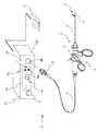
図1ないし図7は、本発明の第1の実施の形態に係り、図1は第1の実施の形態の超音波処置装置を示す全体構成図、図2は図1の装置本体の構成を示す回路ブロック図、図3は図1の超音波処置具の分解状態を示す側面図、図4は図1の超音波処置具全体の組立状態を示す側面図、図5は処置部の詳細構成を示す要部拡大図であり、図5(a)は処置部の上面図、図5(b)は同図(a)の断面図、図6は超音波プローブの形状を示す外観斜視図、図7は図5の処置部の断面図を示し、図7(a)は正常時における処置部の断面図、図7(b)は回転ズレした際の処置部の断面図である。
【0015】
図1に示すように、本実施の形態の超音波処置装置1は、装置本体1Aに超音波処置具2及びフットスイッチ3がそれぞれ接続されている。
また、超音波処置具2は、細長いシース状の挿入部外套管4の先端部に処置部5、基端部に手元側の操作部6がそれぞれ配設されている。ここで、操作部6は、超音波振動を発生する図示しない超音波振動子が内蔵され、処置部5を操作する操作ハンドル8とが設けられている。
更に、挿入部外套管4は、この内部に超音波振動子からの超音波振動を処置部5に伝達する振動伝達部材9が配設されている。この振動伝達部材9の先端部は、挿入部外套管4の先端から外部側に露出される。
【0016】
また、装置本体1Aは、この前面に操作盤12が設けられている。この操作盤12は、電源スイッチ13と、操作表示パネル14と、超音波処置具接続部15とが設けられている。ここで、超音波処置具2の操作部6は、ハンドピースコード16の一端が連結されている。そして、このハンドピースコード16の他端部に配設されたハンドピースプラグ17は、装置本体1Aの超音波処置具接続部15に着脱可能に接続されるようになっている。
【0017】
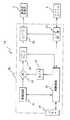
また、装置本体1Aの操作表示パネル14は、超音波処置を行う際の通常運転時の超音波出力の大きさを設定する設定スイッチ18と、この設定スイッチ18で設定される超音波出力の大きさをデジタル表示する表示部19とが設けられている。この設定スイッチ18は、超音波出力の大きさを変更(増減)する出力増加スイッチ18aと、出力低減スイッチ18bとが設けられている。
更に、装置本体1Aは、図2に示すように超音波処置具2内の超音波振動子に電気エネルギを供給するための駆動回路20が内蔵されている。
【0018】
この駆動回路20は、超音波周波数の交流信号を発生する発振回路21と、超音波出力の大きさを指示する信号を生成するD/Aコンバータ22と、このD/Aコンバータ22からの信号に基づいて発振回路21の交流信号の大きさを制御するVCA回路23と、VCA回路23の出力を増幅して超音波処置具2内の超音波振動子を駆動する電力を生成するパワーアンプ24と、駆動回路20の出力ラインを入切するリレー25と、超音波処置装置1の動作を制御する制御回路26と、フットスイッチ3からの操作信号を制御回路26及びリレー25に伝達するインターフェース(I/F)回路27とが設けられている。
【0019】
また、制御回路26は、フットスイッチ3の操作による超音波処置の開始時に超音波処置具2内の超音波振動子からの超音波出力を設定スイッチ18による設定出力値よりも大きくし、超音波処置開始後、予め設定された所定の設定時間が経過した時点で、超音波振動子からの超音波出力が設定出力値になるように制御する運転状態切換え手段が内蔵されている。尚、駆動回路20のリレー25は、超音波処置具接続部15とパワーアンプ24との間に介設されている。
【0020】
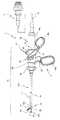
超音波処置具2は、図3及び図4に示すように、3つのユニットに分解可能である。即ち、ハンドルユニット31と、プローブユニット32と、振動子ユニット33とから構成されている。これらの3つのユニット31〜33は、図4で示す状態に組み立てられる。
【0021】
振動子ユニット33は、ハンドルユニット31に着脱可能に連結されるハンドピース34が設けられている。このハンドピース34は、円筒状カバー34a内に超音波振動を発生するための超音波振動子(不図示)が内蔵されている。
この超音波振動子は、先端側に振幅拡大を行なうホーン(不図示)が連結され、このホーンの先端側がプローブユニット32の基端側に取り付けられる。
【0022】
また、円筒状カバー34aは、この先端部にハンドルユニット31の後述する操作部本体6aの振動子接続部6bに着脱可能に連結されるユニット連結部34bが設けられている。このユニット連結部34bの外周面は、リングの一部を切り離したC字型の形状をしている係合リング39(所謂Cリング)が装着されている。尚、係合リング39は、この断面形状が外周を円弧とする略半月状の断面形状に形成されている。
また、円筒状カバー34aの後端部は、端部にハンドピースプラグ17を設けたハンドピースコード16が接続されている。
【0023】
また、プローブユニット32は、振動子ユニット33における図示しないホーンの先端側に着脱可能に連結される細長い略棒状の振動伝達部材9が設けられている。
この振動伝達部材9の基端部は、ホーンのプローブ取付部36aに連結される取付けねじ41aが形成されている。そして、この取付けねじ41aは、振動子ユニット13におけるプローブ取付部36aのねじ穴部にねじ込み固定されている。これにより、プローブユニット32と、振動子ユニット33とは、一体的に組み付けられている。
【0024】
更に、振動伝達部材9は、基端側から伝達される超音波振動の定在波の節の位置(複数個所)にフランジ状の支持体41bが設けられている。この支持体41bは、弾性部材でリング状に形成されている。
また、本実施の形態の振動伝達部材9は、基端部側から2つ目の節の前方に第2段階の振幅拡大を行なう基端側ホーン41cが配設されている。更に、この基端側ホーン41cの先端部側は、超音波振動の伝達を行う中間部41d、最終的な振幅拡大を行う先端側ホーン41e、超音波プローブ41fが順次配設されている。ここで、振動伝達部材9はの最先端部に配置された超音波プローブ41fは、後述する断面形状に形成されている。
【0025】
また、ハンドルユニット31は、細長い挿入シース部31aと、この挿入シース部31aの先端部に配設された先端作用部31bと、挿入シース部31aの基端部に配設された操作部6とから構成される。ここで、ハンドルユニット31の操作部6は、略円筒状の操作部本体6aが設けられている。そして、この操作部本体6aの基端部は、振動子接続部6bが形成されている。
【0026】
また、操作部本体6aは、この外周面に固定ハンドル42と、操作手段を構成する回動可能な可動ハンドル43とが設けられ、固定ハンドル42及び可動ハンドル43によって操作ハンドル8(図1参照)が構成される。
また、操作部本体6aは、図示しない高周波電源装置が接続される高周波接続用の電極ピン44が設けられている。
【0027】
また、固定ハンドル42の上側部分は、円筒状の操作部本体6aと一体成形されている。更に、固定ハンドル42の操作端部は、親指以外の指の複数のものを選択的に差し込める指掛け孔42aが設けられ、可動ハンドル43の操作端部は、同じ手の親指を掛ける指掛け孔43aが設けられている。
【0028】
また、可動ハンドル43の上端部側は、二股状の連結部43bが形成されている。これらの二股状の連結部43bは、操作部本体6aの両側に配置されている。更に、各連結部43bの上端部は、ハンドル枢支軸45が内方向に向けて突設されている。これらのハンドル枢支軸45は、挿入部外套管4の軸線より上側位置の支点で操作部本体6aに連結されている。これにより、可動ハンドル43は、ハンドル枢支軸45によって回動可能に枢支されている。尚、ハンドル枢支軸45は、高周波絶縁用の絶縁キャップが取り付けられている。
【0029】
更に、可動ハンドル43の各連結部43bは、ハンドル枢支軸45の下側に作動軸47が設けられている。この作動軸47は、挿入部外套管4内を挿通する操作ロッド50(図5参照:操作力伝達部材)に進退力を伝達するためのものである。そして、操作ロッド50は、軸方向に進退する動作によって、超音波プローブ41fに対して後述のジョー51に開閉操作を行わせる。即ち、可動ハンドル43と作動軸47とは、操作手段を構成している。尚、作動軸47は、挿入部外套管4の略軸線上に配置されている。
【0030】
本実施の形態では、超音波処置具2は、ハンドルを握って可動ハンドル43を閉操作すると、作動軸47が前側に移動することで、操作ロッド50を前側に押し出し、超音波プローブ41fに対してジョー51が閉じるように構成されている。
【0031】
また、挿入シース部31aは、上述したように、挿入部外套管4が設けられ、この挿入部外套管4の基端部は、回転ノブ48とともに、操作部本体6aの先端部にこの操作部本体6aの中心線の軸回り方向に回転可能に取付けられている。ここで、挿入部外套管4は、図示しない金属管の外周面に絶縁チューブ49が装着されて形成されている。この絶縁チューブ49は、挿入部外套管4の外周面全体を基端部までの大部分被覆する状態に設けられる。
また、ハンドルユニット31は、先端作用部31bに生体組織を把持するための片開き型のジョー51が回動自在に取り付けられている。このジョー51には、後述するように操作ロッド50を連結する。
【0032】
挿入部外套管4は、この先端部にジョー51を保持するジョー保持部52が設けられている。このジョー保持部52は、略管状の保持部材本体52aの先端部が絶縁カバー53で被覆され、高周波電流に対する絶縁が行われている。更に、ジョー51には、生体組織(臓器)を把持する把持部材54が後述の揺動支点61で揺動可能に取り付けられている。
【0033】
また、挿入部外套管4には、プローブユニット32の振動伝達部材9が挿通されている。また、この挿入部外套管4は、振動伝達部材9に併設されて、操作ロッド50が進退自在に挿通されている。尚、操作ロッド50は、挿入部外套管4内に隙間を残して配置されている。
【0034】
次に、処置部5の詳細構成を説明する。
図5(a),(b)に示すようにジョー51は、その取付け部が挿入部外套管4の保持部材本体52aの先端に形成されたスロット52bに挿入され、枢支軸60を介して保持部材本体52aに回動可能に取り付けられている。尚、図5(a),(b)では、絶縁カバー53が取り外されている状態を示している。保持部材本体52aの十分な強度を確保するため、スロット52bは、保持部材本体52aを上下に貫通することなく保持部材本体52aの上側でのみ開口している。即ち、スロット52bが形成された保持部材本体52aの部位の断面形状は、U字型を成している。
【0035】
ジョー51には、先端側に把持部材54が揺動可能に配置されている。具体的には、ジョー51は、把持部材54を挟み込むようにして一体的に連結し、枢支ピン61aにより揺動支点61で把持部材54を揺動可能に取り付けている。
【0036】
この把持部材54は、生体組織に当接する当接面の両端に略鋸歯状の歯部55が形成されている。尚、把持部材54は、例えばPTFE(テフロン:デュポン社商標名)等の低摩擦材料で形成されている。また、把持部材54は、単体では、剛性に乏しいので、図示しない金属製の強度部材を取り付けて剛性を確保しても良い。
【0037】
ジョー51は、その基端部に操作ロッド50の先端連結部50aが連結されている。具体的には、操作ロッド50は、ジョー51の基端側に形成されたスロット62内にその先端連結部50aが挿入される。その状態で、挿入部外套管4の保持部材本体52aに形成された係合孔63と、先端連結部50aに形成された軸孔50bとに枢支ピン64が挿通される。このことにより、操作ロッド50とジョー51とは、枢支軸60の上側で回動可能に連結される。従って、操作ロッド50が進退すると、ジョー51は、枢支軸60を中心に回動(開閉)する。
尚、符号65は、挿入部外套管4内に挿通配置され、振動伝達部材9を保持する保持部材である。
【0038】
ジョー51の閉操作時は、プローブユニット32の超音波プローブ41fに対してジョー51の把持部材54を押し付けることにより、超音波プローブ41fと把持部材54との間で生体組織を把持するようになっている。このとき、把持部材54は、把持した生体組織に応じて揺動し、全面に亘って生体組織に当接するようになっている。そして、把持された生体組織は、高速で振動する超音波プローブ41fとの摩擦熱によって凝固或いは切開等の超音波処置を施される。尚、ジョー51は、生体組織の剥離にも使用される。
【0039】
本実施の形態では、超音波処置具2は、超音波プローブ41fと把持部材54との間で生体組織を把持する際、適切な量の生体組織を把持し、且つ超音波プローブ41fの傾きや偏心に対して把持部材54との接触状態が良好なように構成している。
【0040】
即ち、図6に示すように超音波プローブ41fは、生体組織に当接する処置面として円筒形状の左右両側を軸に平行な平面41Abで削り落として先端側から基端側に亘って一様な円筒状の処置曲面(以下、単に円筒曲面)41Aを形成して構成される。
このことにより、超音波プローブ41fは、超音波振動の振幅を低下することなく、幅を狭く形成することができる。
【0041】
また、超音波プローブ41fは、断面形状が上下方向の厚さの大きい形状であり、把持部材54からの荷重によって撓むことを防止される。よって、超音波プローブ41fは、撓みによる挿入部外套管4の保持部材本体52aや絶縁カバー53への接触が低減される。
【0042】
更に、超音波プローブ41fは、傾いたり偏心したりしても、回転方向の位置決めのずれ、あるいは捩れによる把持部材54との接触状態が変化(接触面積が変動)することなく、安定する。よって、超音波プローブ41fは、生体組織に対して接触状態が変化(接触面積が変動)することなく、超音波処置(凝固切開)性能が安定する。
【0043】
また、超音波プローブ41fは、処置面が円筒曲面41Aであるため、捩り振動に対しても問題なく対応可能である。更に、超音波プローブ41fは、側方の空間が拡大するので構造上の余裕が増し、設計上簡易となる。尚、超音波プローブ41fは、寿命が長くなるように上下とも同じ円筒曲面41Aを形成し、上下逆にして用いるようにしても良い。
【0044】
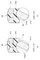
また、この超音波プローブ41fに対向する把持部材54は、図7(a)に示すように生体組織に当接される当接面54Aが円筒状に形成されている。この円筒状部分は、曲率半径が超音波プローブ41fの円筒曲面41Aの曲率半径に等しく設定されている。尚、把持部材54は、円筒状部分の両端側に歯部55が形成されている。
【0045】
そして、超音波プローブ41fは、図7(b)に示すように傾いたり偏心したりして回転ズレしても、円筒曲面41Aが把持部材54の当接面54Aに対して良好な接触状態を維持できる。尚、図7(a),(b)は、生体組織を把持していない状態においての処置部5の断面図を示している。
従って、超音波プローブ41fは、把持部材54との間で生体組織を把持した際に、この把持した生体組織に対して円筒曲面41Aが良好な接触状態を維持することが可能となる。
【0046】
このように構成される超音波処置装置1は、生体組織に対して切開、切除、或いは凝固等の超音波処置を効果的に行うことができる。
術者は、ハンドルユニット31の固定ハンドル42を握り、可動ハンドル43を操作する。すると、この可動ハンドル43のハンドル操作により、挿入シース部31a内で操作ロッド50が進退し、先端作用部31bのジョー51を開閉する。
【0047】
ここで、術者は、ハンドルを握って可動ハンドル43を閉操作する。この場合、図1中で作動軸47は、左側方向に移動する。そして、この作動軸47の動きは、操作ロッド50に伝達されて先端作用部31bのジョー51を閉じる方向に作用する。
そして、ジョー51は、プローブユニット32の超音波プローブ41fに対し、把持部材54を押し付けることで、超音波プローブ41fとの間で生体組織を把持するようになっている。そして、術者は、フットスイッチを踏み込み、把持した生体組織に対して超音波処置を行う。そして、把持された生体組織は、高速で振動する超音波プローブ41fとの摩擦熱によって超音波処置を施される。
【0048】
このとき、把持部材54は、揺動支点61により揺動して超音波プローブ41fとの間で全面に亘って当接して生体組織を把持している。
ここで、超音波処置具2は、上述したように超音波プローブ41fが処置面として円筒曲面41Aを形成しており、一方、把持部材54が当接面54Aとして円弧状に形成されているので、これら超音波プローブ41fと把持部材54との間で適切な量の生体組織を把持できる。
【0049】
そして、超音波処置具2は、超音波プローブ41fが傾いたり偏心したりして回転ズレしても、処置面が把持部材54の当接面54Aに対して良好な接触状態を維持することが可能となり、超音波処置(凝固切開)性能が維持できる。
この結果、超音波処置装置1は、適切な量の生体組織を把持し、且つ超音波プローブ41fの傾きや偏心に対して把持部材54との接触状態が良好となる。
【0050】
(第2の実施の形態)
図8ないし図10は、本発明の第2の実施の形態に係り、図8は第2の実施の形態の超音波処置装置の超音波プローブを示す説明図、図9は正常時における処置部の断面図を示し、図9(a)は正常時における処置部の先端部もしくは基端部の断面図、図9(b)は正常時における処置部の中央部の断面図、図10は回転ズレ時における処置部の断面図を示し、図9(a)は回転ズレ時における処置部の先端部もしくは基端部の断面図、図9(b)は回転ズレ時における処置部の中央部の断面図である。
【0051】
第1の実施の形態は、超音波プローブ41fの形状を先端側から基端側に亘って一様な円筒曲面41Aを形成するように構成しているが、本第2の実施の形態は、更に超音波プローブ41fの形状を先端側から基端側に亘って湾曲するように構成する。それ以外の構成は、上記第1の実施の形態とほぼ同様なので説明を省略し、同じ構成は、同じ符号を付して説明する。
【0052】
即ち、図8に示すように本第2の実施の形態の超音波処置装置は、振動伝達部材9Bの先端側に配設された超音波プローブ41fbが先端側から基端側に亘って湾曲するように円筒曲面(円筒状の処置曲面)41Bを形成されている。尚、図8の下側の投影図は、円筒曲面41Bを投影したものである。
【0053】
この超音波プローブ41fbの円筒曲面41Bは、先端側から基端側に亘って湾曲している。このことにより、超音波プローブ41fbは、傾いたり偏心したりして回転ズレしても、先端側から基端側に亘って回転方向の位置決めのずれ、あるいは捩れによるジョー51bの把持部材54bとの接触状態が変化(接触面積が変動)することなく、安定する。よって、超音波プローブ41fbは、生体組織に対して接触状態が変化(接触面積が変動)することなく、超音波処置(凝固切開)性能が安定する。
また、超音波プローブ41fbは、先端側から基端側に亘って把持部材54bとの接触状態の変動による偏摩耗が低減するので寿命が長くなる。
【0054】
また、超音波プローブ41fbは、上記第1の実施の形態で説明したのと同様に超音波振動の振幅を低下することなく、幅を狭く形成することができる。また、超音波プローブ41fbは、断面形状が上下方向の厚さの大きい形状であり、把持部材54bからの荷重によって撓むことを防止される。よって、超音波プローブ41fbは、撓みによる挿入部外套管4の保持部材本体52aや絶縁カバー53への接触が低減され、超音波処置(凝固切開)性能が安定する。
【0055】
また、超音波プローブ41fbは、処置面が円筒曲面41Bで且つ湾曲しているため、捩り振動に対しても問題なく対応可能である。更に、超音波プローブ41fbは、把持部材54bとともに複雑な3次元形状でないので、旋盤加工と、2軸(X、Y軸)のフライス加工とで、容易に加工可能であり、コストが低下する。
【0056】
また、この超音波プローブ41fbに対向する把持部材54bは、図9に示すように生体組織に当接される当接面54Abが先端側から基端側に亘って超音波プローブ41fbの円筒曲面41Bの湾曲形状に整合するよう、円筒状で且つ湾曲するように形成されている。この円筒状部分は、曲率半径が超音波プローブ41fbの円筒曲面41Bの曲率半径に等しく設定されている。
【0057】
更に、具体的に説明すると、例えば、把持部材54bは、先端部もしくは基端部において、超音波プローブ41fbの形状に応じて図9(a)に示すように形成されている。また、把持部材54bは、中央部において、超音波プローブ41fbの形状に応じて図9(b)に示すように形成されている。
【0058】
そして、超音波プローブ41fbは、傾いたり偏心したりして回転ズレしても、図10(a)に示す先端部もしくは基端部、もしくは図10(b)に示す中央部において、円筒曲面41Bが把持部材54bの当接面54Abに対して良好な接触状態を維持できる。尚、図9(a),(b),図10(a),(b)は、生体組織を把持していない状態においての処置部5Bの断面図を示している。
従って、超音波プローブ41fbは、把持部材54bとの間で生体組織を把持した際に、この把持した生体組織に対して円筒曲面41Bが良好な接触状態を維持することが可能となる。
【0059】
このように構成される超音波処置装置は、上記第1の実施の形態で説明したのと同様に生体組織を把持して、この把持した生体組織に対して切開、切除、或いは凝固等の超音波処置を行う。
ここで、術者は、被検体に対して超音波処置具をまっすぐに使うわけでなく右側又は左側から斜めに挿入して用いる。この場合、超音波処置具の先端側(超音波プローブ)がまっすぐのものより、湾曲したものの方が視野内での見える部分が大きくなるため使い勝手(操作性)が良い。
【0060】
本実施の形態では、超音波処置具2は、上述したように超音波プローブ41fbが処置面として先端側から基端側に亘って湾曲するように円筒曲面41Bを形成しており、一方、把持部材54bが当接面54Abとして先端側から基端側に亘って超音波プローブ41fbの湾曲形状に整合するよう湾曲して形成されているので、これら超音波プローブ41fbと把持部材54bとの間で適切な量の生体組織を把持できる。
【0061】
そして、超音波処置具2は、超音波プローブ41fbが傾いたり偏心したりして回転ズレしても、先端側から基端側に亘って超音波プローブ41fbの処置面が把持部材54bの当接面54Abに対して良好な接触状態を維持することが可能となり、超音波処置(凝固切開)性能が維持できる。
この結果、本第2の実施の形態の超音波処置装置は、上記第1の実施の形態と同様な効果を得ることに加え、使い勝手(操作性)が良いという効果を得る。
【0062】
ところで、上述した超音波処置装置は、超音波振動子で発生した縦方向の超音波振動により摩擦熱を発生させて、凝固切開(超音波)処置を行なうようになっている。
しかしながら、超音波処置装置は、高価な超音波振動子を用いている。また、超音波処置装置は、超音波プローブに発生する応力が大きいので強度上、耐久性を考慮して設計する必要があり、その分コストがかかる。
【0063】
そこで、超音波振動によらず生体組織に対して摩擦熱を発生させて凝固切開(摩擦熱)処置を行う安価な摩擦熱処置装置の提供が望まれていた。
図11及び図12を参照して摩擦熱処置装置の構成例を説明する。
図11及び図12は摩擦熱処置装置の構成例に係わり、図11は摩擦熱処置装置を示す構成図、図12は他の摩擦熱処置装置を示す構成図である。
【0064】
図11に示すように摩擦熱処置装置100は、摩擦熱処置具102と、この摩擦熱処置具102を接続して電気エネルギを供給するための図示しない装置本体とから構成される。
摩擦熱処置具102は、細長いシース状の挿入部外套管103の先端部に処置部104、基端部に手元側の操作部105がそれぞれ配設されている。ここで、操作部105は、モータ等の回転駆動部106が取り付けられ、処置部104を操作する操作ハンドル107とが設けられている。
【0065】
更に、挿入部外套管103は、この内部に回転駆動部106からの回転力を処置部104に伝達する回転力伝達部材111が配設されている。この回転力伝達部材111の先端部は、挿入部外套管103の先端から外部側に露出される。
摩擦熱処置具102は、細長い略棒状の回転力伝達部材111が設けられている。この回転力伝達部材111は、基端側及び先端側に軸受け部112が設けられている。
【0066】
また、回転力伝達部材111は、略円形の断面形状に形成されている摩擦熱プローブ111aが最先端部に回転自在に設けられている。
操作部105は、この外周面に固定ハンドル113と、回動可能な可動ハンドル114とが設けられ、固定ハンドル113及び可動ハンドル114によって操作ハンドル107が構成される。
【0067】
固定ハンドル113は、円筒状の操作部105と一体成形されている。
可動ハンドル114は、図示しないハンドル枢支軸によって回動可能に枢支されている。更に、可動ハンドル114は、ハンドル枢支軸の下側に作動軸115が設けられている。
【0068】
この作動軸115は、軸方向に進退する進退部材116に接続されている。進退部材116は、挿入部外套管103内を挿通する操作力伝達部材117に進退力を伝達するためものである。そして、操作力伝達部材117は、進退部材116の進退動作によって、摩擦熱プローブ111aに対してジョー118に開閉操作を行わせるようになっている。
そして、摩擦熱処置具102は、ハンドルを握って可動ハンドル114を閉操作すると、摩擦熱プローブ111aに対してジョー118が閉じるように構成されている。
【0069】
また、摩擦熱処置具102は、生体組織を把持するための片開き型のジョー118が回動自在に取り付けられている。このジョー118は、操作力伝達部材117を連結している。
また、挿入部外套管103は、回転力伝達部材111が挿通されている。また、この挿入部外套管103は、回転力伝達部材111に併設されて、操作力伝達部材117が進退自在に挿通されている。
【0070】
このように構成されている摩擦熱処置装置100は、生体組織に対して切開、切除、或いは凝固等の処置を効果的に行うことができる。
術者は、固定ハンドル113を握り、可動ハンドル114を操作する。すると、この可動ハンドル114のハンドル操作により、進退部材116が進退動作してこの進退動作が操作力伝達部材117に伝達されて進退し、ジョー118を開閉する。そして、ジョー118は、摩擦熱プローブ111aとの間で生体組織を把持する。そして、術者は、図示しないフットスイッチを踏み込み、把持した生体組織に対して凝固切開(摩擦熱)処置を行う。
【0071】
ここで、摩擦熱処置装置100は、フットスイッチからのオン信号により、装置本体から摩擦熱処置具102へ電気エネルギが供給されて回転駆動部106を駆動する。摩擦熱処置具102は、回転駆動部106からの回転力が回転力伝達部材111を介して摩擦熱プローブ111aへ伝達される。そして、把持された生体組織は、高速で回転する摩擦熱プローブ111aとの摩擦熱によって凝固切開(摩擦熱)処置を施される。
【0072】
この結果、摩擦熱処置装置100は、超音波処置装置に比べて摩擦熱プローブ111a内に発生する応力が小さいので強度上有利である。また、摩擦熱処置装置100は、超音波処置装置に比べて摩擦熱プローブ111a形状の自由度が大きい。更に、摩擦熱処置装置100は、超音波処置装置に比べて摩擦熱プローブ111aの所定位置による発熱量の違いがない。
【0073】
また、摩擦熱処置装置100は、音響特性と無関係なので、長手方向の寸法に制約がない(有効長の設定が自由である)。同じく、摩擦熱処置装置100は、形状・寸法の精度のみを確保すればいいので製造が容易である。
これにより、摩擦熱処置装置100は、超音波振動によらず生体組織に対して摩擦熱を発生させて凝固切開(摩擦熱)処置を安価に行うことが可能である。
【0074】
また、摩擦熱処置装置は、摩擦熱プローブ111aに回転力を伝達するのみので良いので、図12に示すよう挿入部に柔軟性を持たせた軟性の挿入部を設けて構成しても良い。
図12に示すように摩擦熱処置装置120は、軟性の挿入部を有する摩擦熱処置具122と、この摩擦熱処置具122を接続して電気エネルギを供給するための図示しない装置本体とから構成される。
【0075】
摩擦熱処置具122は、図示しない回転駆動部を設けた操作部123と、軟性の挿入部としての摩擦熱プローブ124と、この摩擦熱プローブ124と操作部123とを連結する回転力伝達部材であるフレキシブルシャフト125とで構成され、摩擦熱プローブ124に回転力を伝達するように構成されている。
【0076】
このように構成されている摩擦熱処置装置120は、生体組織に対して切開、切除、或いは凝固等の処置を効果的に行うことができる。
術者は、フレキシブルシャフト125を被検体内に挿入して摩擦熱プローブ124を目的部位に導く。そして、術者は、図示しないフットスイッチを踏み込み、目的部位の生体組織に対して凝固切開(摩擦熱)処置を行う。
【0077】
ここで、摩擦熱処置装置120は、フットスイッチからのオン信号により、装置本体から摩擦熱処置具122へ電気エネルギが供給されて回転駆動部が駆動する。摩擦熱処置具122は、回転駆動部からの回転力がフレキシブルシャフト125を介して摩擦熱プローブ124へ伝達される。そして、生体組織は、高速で回転する摩擦熱プローブ124との摩擦熱によって凝固切開(摩擦熱)処置を施される。
【0078】
これにより、摩擦熱処置装置120は、上記摩擦熱処置装置100と同様な効果を得る上に、回転力伝達部材としてフレキシブルシャフト125を用いることで軟性の挿入部が容易に実現できる。
本発明は、上述した実施の形態に限定されるものではなく、本発明の要旨を変えない範囲において、種々の変更、改変等が可能である。
【0079】
[付記]
(付記項1) 超音波振動子で発生した超音波振動を伝達し、生体組織を処置する超音波プローブと、
前記超音波プローブに対峙して回動自在に支持され、この超音波プローブとの間に生体組織を把持するジョーと、
前記ジョーに設け、生体組織に当接される当接面が円筒状に形成された把持部材と、
を具備し、
前記超音波プローブは、生体組織に当接する処置面として円筒形状の左右両側を所定の平面投影形状で削り落として円筒状の処置曲面を形成したことを特徴とする超音波処置装置。
【0080】
(付記項2) 超音波振動子で発生した超音波振動を伝達し、生体組織を処置する超音波プローブと、
前記超音波プローブに対峙して回動自在に支持され、この超音波プローブとの間に生体組織を把持するジョーと、
前記ジョーに設け、生体組織に当接される当接面が円筒状に形成された把持部材と、
前記超音波振動子を制御駆動するための駆動回路と、
を具備し、
前記超音波プローブは、生体組織に当接する処置面として円筒形状の左右両側を所定の平面投影形状で削り落として円筒状の処置曲面を形成したことを特徴とする超音波処置装置。
【0081】
(付記項3) 超音波振動子で発生した超音波振動を伝達し、生体組織を処置する超音波プローブと、
前記超音波プローブに対峙して回動自在に支持され、この超音波プローブとの間に生体組織を把持するジョーと、
前記ジョーに設け、生体組織に当接される当接面が円弧状に形成された把持部材と、
を具備し、
前記超音波プローブは、生体組織に当接する処置面として円筒形状の左右両側を直線状に削り落として円筒曲面を形成したことを特徴とする超音波処置装置。
【0082】
(付記項4) 超音波振動子で発生した超音波振動を伝達し、生体組織を処置する超音波プローブと、
前記超音波プローブに対峙して回動自在に支持され、この超音波プローブとの間に生体組織を把持するジョーと、
前記ジョーに設け、生体組織に当接される当接面が円弧状に形成された把持部材と、
前記超音波振動子を制御駆動するための駆動回路と、
を具備し、
前記超音波プローブは、生体組織に当接する処置面として円筒形状の左右両側を直線状に削り落として円筒曲面を形成したことを特徴とする超音波処置装置。
【0083】
(付記項5) 前記超音波プローブは、先端側から基端側に亘って前記円筒状の処置曲面を一様に形成したことを特徴とする付記項1又は2に記載の超音波処置装置。
(付記項6) 前記超音波プローブは、先端側から基端側に亘って前記円筒状の処置曲面を湾曲するように形成したことを特徴とする付記項1又は2に記載の超音波処置装置。
【0084】
(付記項7) 前記超音波プローブは、先端側から基端側に亘って前記円筒曲面を一様に形成したことを特徴とする付記項3又は4に記載の超音波処置装置。
(付記項8) 前記超音波プローブは、先端側から基端側に亘って前記円筒曲面を湾曲するように形成したことを特徴とする付記項3又は4に記載の超音波処置装置。
【0085】
(付記項9) 回転力を発生する回転駆動部と、
前記回転駆動部に接続され、この回転駆動部で発生した回転力を先端側へ伝達する回転力伝達部材と、
前記回転力伝達部材の先端側に連結され、この回転力伝達部材から伝達された回転力により回転自在に回転して生体組織を処置する摩擦熱プローブと、
を具備したことを特徴とする摩擦熱処置装置。
【0086】
(付記項10) 前記摩擦熱プローブに対峙して回動自在であり、この摩擦熱プローブとの間で生体組織を把持するジョーと、
前記ジョーを前記摩擦熱プローブに対して開閉操作する操作手段と、
前記ジョーと前記操作手段との間を連結し、前記操作手段からの操作力を前記ジョー側に伝達する操作力伝達部材と、
を更に具備したことを特徴とする付記項9に記載の摩擦熱処置装置。
【0087】
(付記項11) 前記回転力伝達部材は、前記摩擦熱プローブと前記回転駆動部とを連結するフレキシブルシャフトであり、このフレキシブルシャフトと前記摩擦熱プローブとで軟性の挿入部を構成していることを特徴とする付記項9に記載の摩擦熱処置装置。
【0088】
(付記項12) 回転力を発生する回転駆動部と、
前記回転駆動部に接続され、この回転駆動部で発生した回転力を先端側へ伝達する回転力伝達部材と、
前記回転力伝達部材の先端側に連結され、この回転力伝達部材から伝達された回転力により回転自在に回転して生体組織を処置する摩擦熱プローブと、
前記摩擦熱プローブに対峙して回動自在であり、この摩擦熱プローブとの間で生体組織を把持するジョーと、
前記ジョーを前記摩擦熱プローブに対して開閉操作する操作手段と、
前記ジョーと前記操作手段との間を連結し、前記操作手段からの操作力を前記ジョー側に伝達する操作力伝達部材と、
を具備したことを特徴とする摩擦熱処置装置。
【0089】
【発明の効果】
以上説明したように本発明によれば、適切な量の生体組織を把持し、且つ超音波プローブの傾きや偏心に対して把持部材との接触状態が良好な超音波処置装置を実現できる。
【図面の簡単な説明】
【図1】第1の実施の形態の超音波処置装置を示す全体構成図
【図2】図1の装置本体の構成を示す回路ブロック図
【図3】図1の超音波処置具の分解状態を示す側面図
【図4】図1の超音波処置具全体の組立状態を示す側面図
【図5】処置部の詳細構成を示す要部拡大図
【図6】超音波プローブの形状を示す外観斜視図
【図7】図5の処置部の断面図
【図8】第2の実施の形態の超音波処置装置の超音波プローブを示す説明図
【図9】正常時における処置部の断面図
【図10】回転ズレ時における処置部の断面図
【図11】摩擦熱処置装置を示す構成図
【図12】他の摩擦熱処置装置を示す構成図
【符号の説明】
1…超音波処置装置
1A…装置本体
2…超音波処置具
4…挿入部外套管
5…処置部
6…操作部
9…振動伝達部材
31…ハンドルユニット
32…プローブユニット
33…振動子ユニット
41A…円筒曲面(円筒状の処置曲面)
41Ab…平面
41f…超音波プローブ
50…操作ロッド
51…ジョー
52…ジョー保持部
52a…保持部本体
54…把持部材
55…歯部[0001]
TECHNICAL FIELD OF THE INVENTION
The present invention relates to an ultrasonic treatment apparatus that performs ultrasonic treatment such as incision, excision, or coagulation of a living tissue while grasping the living tissue.
[0002]
[Prior art]
In general, an ultrasonic treatment apparatus performs ultrasonic treatment such as incision, excision, or coagulation on a living tissue.
Such an ultrasonic treatment apparatus has, for example, an ultrasonic vibrator provided at an operation unit on the hand side, and transmits ultrasonic vibration generated by the ultrasonic vibrator to treat living tissue. An ultrasonic probe is provided on the distal end side.
[0003]
Further, the ultrasonic treatment apparatus is provided with a jaw rotatably supported opposite the ultrasonic probe. The jaw is provided with a gripping member with which the living tissue is brought into contact.
In the ultrasonic treatment apparatus, a movable handle for opening and closing the jaw with respect to the ultrasonic probe is provided in the operation unit, and an operation rod for transmitting an operation force from the movable handle to the jaw is provided in the axial direction. It is inserted so that it can advance and retreat.
[0004]
In the ultrasonic treatment apparatus, the operation rod moves forward and backward in the axial direction with the operation of the movable handle, and the ultrasonic operation is performed by closing the jaw with respect to the ultrasonic probe in conjunction with the movement of the operation rod. The living tissue is gripped between the probe and the gripping member of the jaw.
Subsequently, in this state, the ultrasonic treatment apparatus transmits ultrasonic vibrations from the ultrasonic transducer to the ultrasonic probe, thereby performing ultrasonic waves such as incision, excision, or coagulation on the grasped living tissue. The treatment is applied.
[0005]
Such a conventional ultrasonic treatment apparatus, for example, as described in JP-A-2000-296132, while the distal end side of the ultrasonic probe is formed in a cylindrical shape as a treatment surface that comes into contact with the biological tissue, A configuration in which a gripping member is formed in an arc shape as a contact surface that contacts a living tissue has been proposed.
In the ultrasonic treatment apparatus described in JP-A-2000-296132, even when the ultrasonic probe is inclined or eccentric, the ultrasonic probe has the distal end side and the gripping member formed as described above. Biological tissue can be uniformly gripped between the probe and the gripping member, and therefore, the gripping pressure (grip load) applied to the biological tissue from the gripping member can be uniformed.
[0006]
However, the ultrasonic treatment apparatus described in Japanese Patent Application Laid-Open No. 2000-296132 has a circular cross section at the distal end side of the ultrasonic probe, so that the ultrasonic probe has a large width and a large volume, so that the amplitude of transmitted ultrasonic vibration decreases. However, the width of the tip side is widened and the precision is reduced.
Therefore, the ultrasonic treatment apparatus described in Japanese Patent Application Laid-Open No. 2000-296132 requires a large amount of heat to be applied to a large amount of tissue because the contact area with the grasped living tissue becomes large, and the ultrasonic treatment takes time. .
[0007]
Therefore, in the conventional ultrasonic treatment apparatus, for example, the treatment surface is made flat by making the cross-sectional shape on the distal end side of the ultrasonic probe substantially rectangular so that the contact area is narrow so that the contact surface of the gripping member is narrow. Some are formed in a planar shape.
However, in the above-mentioned ultrasonic treatment apparatus, the portion holding the living tissue with an appropriate force becomes narrow, and the incision becomes superior. Further, in the ultrasonic treatment apparatus, when the ultrasonic probe is tilted or eccentric, the contact state with the living tissue changes (contact area changes), and there is a possibility that the ultrasonic treatment (coagulation and incision) performance may change. there were.
[0008]
On the other hand, a conventional ultrasonic treatment apparatus, on the other hand, has an ultrasonic probe having a cross-sectional shape in which a ridge line having an edge is formed in a part of a cylinder as described in, for example, JP-A-11-192233. Are formed so that the tip side of the ridge line is formed, and the side of the ridge line and the opposite side are properly used according to the purpose.
[0009]
[Patent Document 1]
JP 2000-296132 A
[0010]
[Patent Document 2]
JP-A-11-192233
[0011]
[Problems to be solved by the invention]
However, the ultrasonic treatment apparatus described in Japanese Patent Application Laid-Open No. H11-192233 tends to cause fluctuations in ultrasonic treatment (coagulation incision) performance on the ridgeline side. Further, in the ultrasonic treatment apparatus described in Japanese Patent Application Laid-Open No. H11-192233, it is complicated to process the distal end side of the ultrasonic probe as described above, and the cost is high.
[0012]
The present invention has been made in view of these circumstances, and an ultrasonic treatment apparatus that grips an appropriate amount of living tissue and has a good contact state with a gripping member with respect to the inclination and eccentricity of an ultrasonic probe. The purpose is to provide.
[0013]
[Means for Solving the Problems]
An ultrasonic treatment apparatus according to
Further, an ultrasonic treatment apparatus according to
With this configuration, it is possible to realize an ultrasonic treatment apparatus that grips an appropriate amount of living tissue and has a good contact state with the gripping member with respect to the inclination and eccentricity of the ultrasonic probe.
[0014]
BEST MODE FOR CARRYING OUT THE INVENTION
Hereinafter, embodiments of the present invention will be described with reference to the drawings.
(First Embodiment)
FIGS. 1 to 7 relate to a first embodiment of the present invention. FIG. 1 is an overall configuration diagram showing an ultrasonic treatment apparatus according to the first embodiment. FIG. FIG. 3 is a side view showing the disassembled state of the ultrasonic treatment device of FIG. 1, FIG. 4 is a side view showing the assembled state of the entire ultrasonic treatment device of FIG. 1, and FIG. 5 (a) is a top view of the treatment section, FIG. 5 (b) is a cross-sectional view of FIG. 5 (a), FIG. 6 is an external perspective view showing the shape of the ultrasonic probe, 7 shows a cross-sectional view of the treatment section of FIG. 5, FIG. 7 (a) is a cross-sectional view of the treatment section in a normal state, and FIG. 7 (b) is a cross-sectional view of the treatment section when the rotation is shifted.
[0015]
As shown in FIG. 1, in an
In the
Further, a
[0016]
The
[0017]
The
Further, as shown in FIG. 2, the apparatus
[0018]
The
[0019]
Further, the
[0020]
The
[0021]
The
A horn (not shown) for expanding the amplitude is connected to the distal end of the ultrasonic transducer, and the distal end of the horn is attached to the proximal end of the
[0022]
The
The rear end of the
[0023]
Further, the
At the base end of the
[0024]
Further, the
Further, in the
[0025]
Further, the
[0026]
The operation unit body 6a is provided with a fixed
The operation section main body 6a is provided with an
[0027]
The upper portion of the fixed
[0028]
Further, a bifurcated connecting
[0029]
Further, an operating
[0030]
In the present embodiment, when the
[0031]
As described above, the
In the
[0032]
The insertion portion
[0033]
Further, the
[0034]
Next, a detailed configuration of the
As shown in FIGS. 5A and 5B, the attachment portion of the
[0035]
The
[0036]
The gripping
[0037]
The distal
[0038]
When the
[0039]
In the present embodiment, when grasping the living tissue between the
[0040]
That is, as shown in FIG. 6, the
Thus, the
[0041]
The
[0042]
Further, even if the
[0043]
Further, since the treatment surface of the
[0044]
In addition, as shown in FIG. 7A, the gripping
[0045]
Then, even if the
Therefore, when the
[0046]
The
The operator grasps the fixed
[0047]
Here, the operator holds the handle and closes the
The
[0048]
At this time, the gripping
Here, in the
[0049]
The
As a result, the
[0050]
(Second embodiment)
8 to 10 relate to a second embodiment of the present invention, FIG. 8 is an explanatory view showing an ultrasonic probe of the ultrasonic treatment apparatus according to the second embodiment, and FIG. 9 is a treatment unit in a normal state. 9A is a cross-sectional view of a distal end portion or a proximal end portion of the treatment section in a normal state, FIG. 9B is a cross-sectional view of a central portion of the treatment section in a normal state, and FIG. FIG. 9A is a cross-sectional view of a distal end portion or a proximal end portion of the treatment section at the time of rotational displacement, and FIG. 9B is a cross-sectional view of a central portion of the treatment section at the time of rotational displacement. It is sectional drawing.
[0051]
In the first embodiment, the shape of the
[0052]
That is, as shown in FIG. 8, in the ultrasonic treatment apparatus according to the second embodiment, the ultrasonic probe 41fb disposed on the distal side of the
[0053]
The cylindrical
Further, the ultrasonic probe 41fb has a longer life because uneven wear due to a change in the contact state with the gripping
[0054]
Further, the ultrasonic probe 41fb can be formed to have a small width without reducing the amplitude of the ultrasonic vibration as in the case of the first embodiment. The ultrasonic probe 41fb has a cross-sectional shape having a large thickness in the vertical direction, and is prevented from bending due to a load from the gripping
[0055]
Further, since the treatment surface of the ultrasonic probe 41fb is a cylindrical
[0056]
In addition, as shown in FIG. 9, the gripping
[0057]
More specifically, for example, the gripping
[0058]
Then, even if the ultrasonic probe 41fb is tilted or eccentric and rotationally displaced, the cylindrical
Therefore, when the ultrasonic probe 41fb grasps the living tissue between the ultrasonic probe 41fb and the grasping
[0059]
The ultrasonic treatment apparatus configured as described above grasps a living tissue in the same manner as described in the first embodiment, and performs incision, resection, or coagulation on the grasped living tissue. Perform sonication.
Here, the surgeon does not use the ultrasonic treatment tool straight on the subject but inserts the ultrasonic treatment tool obliquely from the right side or the left side. In this case, the ultrasonic treatment device is more convenient to use (operability) because a curved one has a larger visible portion in the visual field than a straight one on the distal end side (ultrasonic probe).
[0060]
In the present embodiment, as described above, the
[0061]
Then, even when the ultrasonic probe 41fb is tilted or eccentric and rotationally displaced, the treatment surface of the ultrasonic probe 41fb is brought into contact with the gripping
As a result, the ultrasonic treatment apparatus according to the second embodiment has the same effect as that of the first embodiment, and also has the effect of good usability (operability).
[0062]
By the way, the above-mentioned ultrasonic treatment apparatus performs a coagulation incision (ultrasonic) treatment by generating frictional heat by longitudinal ultrasonic vibration generated by an ultrasonic vibrator.
However, the ultrasonic treatment apparatus uses an expensive ultrasonic transducer. Further, since the ultrasonic treatment device generates a large stress in the ultrasonic probe, it is necessary to design the ultrasonic treatment device in consideration of strength and durability, and the cost is accordingly increased.
[0063]
Therefore, it has been desired to provide an inexpensive frictional heat treatment apparatus that performs coagulation and incision (frictional heat) treatment by generating frictional heat on living tissue without using ultrasonic vibration.
A configuration example of the frictional heat treatment device will be described with reference to FIGS. 11 and 12.
11 and 12 relate to a configuration example of the frictional heat treatment device, FIG. 11 is a configuration diagram showing a friction heat treatment device, and FIG. 12 is a configuration diagram showing another friction heat treatment device.
[0064]
As shown in FIG. 11, the frictional
In the frictional
[0065]
Further, a rotational
The frictional
[0066]
The rotational
The
[0067]
The fixed
The
[0068]
The operating
The frictional
[0069]
Further, the frictional
Further, the rotational
[0070]
The frictional
The surgeon grasps the fixed
[0071]
Here, in the frictional
[0072]
As a result, the frictional
[0073]
Further, since the frictional
Thus, the frictional
[0074]
Further, since the frictional heat treatment apparatus only needs to transmit the rotational force to the
As shown in FIG. 12, the frictional
[0075]
The frictional
[0076]
The frictional
The surgeon inserts the
[0077]
Here, in the frictional
[0078]
Thus, the frictional
The present invention is not limited to the above-described embodiment, and various changes and modifications can be made without departing from the spirit of the present invention.
[0079]
[Appendix]
(Additional Item 1) An ultrasonic probe that transmits ultrasonic vibration generated by an ultrasonic transducer and treats a living tissue,
A jaw that is rotatably supported in opposition to the ultrasonic probe and holds a living tissue between the ultrasonic probe and
Provided on the jaw, a gripping member having a cylindrical contact surface that is in contact with the living tissue,
With
The ultrasonic treatment apparatus is characterized in that the ultrasonic probe has a cylindrical treatment curved surface formed by shaving both left and right sides of a cylindrical shape as a treatment surface in contact with a living tissue in a predetermined plane projection shape.
[0080]
(Additional Item 2) An ultrasonic probe that transmits ultrasonic vibration generated by the ultrasonic transducer and treats a living tissue,
A jaw that is rotatably supported in opposition to the ultrasonic probe and holds a living tissue between the ultrasonic probe and
Provided on the jaw, a gripping member having a cylindrical contact surface that is in contact with the living tissue,
A drive circuit for controlling and driving the ultrasonic transducer,
With
The ultrasonic treatment apparatus is characterized in that the ultrasonic probe has a cylindrical treatment curved surface formed by shaving both left and right sides of a cylindrical shape as a treatment surface in contact with a living tissue in a predetermined plane projection shape.
[0081]
(Additional Item 3) An ultrasonic probe that transmits ultrasonic vibration generated by the ultrasonic transducer and treats a living tissue,
A jaw that is rotatably supported in opposition to the ultrasonic probe and holds a living tissue between the ultrasonic probe and
A grip member provided on the jaw and having a contact surface that is in contact with a living tissue is formed in an arc shape,
With
An ultrasonic treatment apparatus, wherein the ultrasonic probe has a cylindrical curved surface formed by linearly cutting off the left and right sides of a cylindrical shape as a treatment surface that comes into contact with a living tissue.
[0082]
(Additional Item 4) An ultrasonic probe that transmits ultrasonic vibration generated by the ultrasonic transducer and treats a living tissue,
A jaw that is rotatably supported in opposition to the ultrasonic probe and holds a living tissue between the ultrasonic probe and
A grip member provided on the jaw and having a contact surface that is in contact with a living tissue is formed in an arc shape,
A drive circuit for controlling and driving the ultrasonic transducer,
With
An ultrasonic treatment apparatus, wherein the ultrasonic probe has a cylindrical curved surface formed by linearly cutting off the left and right sides of a cylindrical shape as a treatment surface that comes into contact with a living tissue.
[0083]
(Additional Item 5) The ultrasonic treatment apparatus according to
(Additional Item 6) The ultrasonic treatment apparatus according to
[0084]
(Additional Item 7) The ultrasonic treatment apparatus according to
(Additional Item 8) The ultrasonic treatment apparatus according to
[0085]
(Additional Item 9) A rotation drive unit that generates a rotation force,
A rotational force transmitting member connected to the rotational drive unit and transmitting the rotational force generated by the rotational drive unit to the distal end side;
A frictional heat probe connected to the distal end side of the rotational force transmitting member, rotatably rotating by the rotational force transmitted from the rotational force transmitting member, and treating a living tissue,
A friction heat treatment apparatus comprising:
[0086]
(Supplementary Note 10) A jaw that is rotatable to face the frictional heat probe and grips a living tissue with the frictional heat probe,
Operating means for opening and closing the jaws with respect to the frictional heat probe,
An operating force transmitting member that connects the jaw and the operating means and transmits an operating force from the operating means to the jaw side;
Item 10. The frictional heat treatment apparatus according to
[0087]
(Supplementary Note 11) The rotational force transmitting member is a flexible shaft that connects the friction heat probe and the rotation drive unit, and the flexible shaft and the friction heat probe constitute a flexible insertion unit. The frictional heat treatment apparatus according to
[0088]
(Additional Item 12) A rotation drive unit that generates a rotational force,
A rotational force transmitting member connected to the rotational drive unit and transmitting the rotational force generated by the rotational drive unit to the distal end side;
A frictional heat probe connected to the distal end side of the rotational force transmitting member, rotatably rotating by the rotational force transmitted from the rotational force transmitting member, and treating a living tissue,
A jaw that is rotatable in opposition to the frictional heat probe and grips a living tissue between the frictional heat probe,
Operating means for opening and closing the jaws with respect to the frictional heat probe,
An operating force transmitting member that connects the jaw and the operating means and transmits an operating force from the operating means to the jaw side;
A friction heat treatment apparatus comprising:
[0089]
【The invention's effect】
As described above, according to the present invention, it is possible to realize an ultrasonic treatment apparatus that grips an appropriate amount of living tissue and has a good contact state with the gripping member with respect to the inclination and eccentricity of the ultrasonic probe.
[Brief description of the drawings]
FIG. 1 is an overall configuration diagram showing an ultrasonic treatment apparatus according to a first embodiment.
FIG. 2 is a circuit block diagram showing a configuration of the apparatus main body of FIG.
FIG. 3 is a side view showing a disassembled state of the ultrasonic treatment device in FIG. 1;
FIG. 4 is a side view showing an assembled state of the entire ultrasonic treatment instrument in FIG. 1;
FIG. 5 is an enlarged view of a main part showing a detailed configuration of a treatment unit.
FIG. 6 is an external perspective view showing the shape of an ultrasonic probe.
FIG. 7 is a cross-sectional view of the treatment section of FIG.
FIG. 8 is an explanatory view showing an ultrasonic probe of the ultrasonic treatment apparatus according to the second embodiment.
FIG. 9 is a cross-sectional view of the treatment section in a normal state.
FIG. 10 is a cross-sectional view of the treatment section at the time of rotational displacement.
FIG. 11 is a configuration diagram showing a friction heat treatment device.
FIG. 12 is a configuration diagram showing another frictional heat treatment apparatus.
[Explanation of symbols]
1. Ultrasonic treatment device
1A: Device body
2. Ultrasonic treatment tool
4: Insert tube
5 Treatment section
6 Operation unit
9 ... Vibration transmission member
31 Handle unit
32 ... Probe unit
33 ... Transducer unit
41A: cylindrical curved surface (cylindrical treatment curved surface)
41Ab ... plane
41f ... ultrasonic probe
50 ... Operation rod
51 ... Joe
52 ... Jaw holding part
52a: Main body of holding section
54 ... Grip member
55 ... Tooth
Claims (2)
Translated fromJapanese前記超音波プローブに対峙して回動自在に支持され、この超音波プローブとの間に生体組織を把持するジョーと、
前記ジョーに設け、生体組織に当接される当接面が円筒状に形成された把持部材と、
を具備し、
前記超音波プローブは、生体組織に当接する処置面として円筒形状の左右両側を所定の平面投影形状で削り落として円筒状の処置曲面を形成したことを特徴とする超音波処置装置。An ultrasonic probe that transmits ultrasonic vibration generated by an ultrasonic transducer and treats a living tissue,
A jaw that is rotatably supported in opposition to the ultrasonic probe and holds a living tissue between the ultrasonic probe and
Provided on the jaw, a gripping member having a cylindrical contact surface that is in contact with the living tissue,
With
The ultrasonic treatment apparatus is characterized in that the ultrasonic probe has a cylindrical treatment curved surface formed by shaving both left and right sides of a cylindrical shape as a treatment surface in contact with a living tissue in a predetermined plane projection shape.
前記超音波プローブに対峙して回動自在に支持され、この超音波プローブとの間に生体組織を把持するジョーと、
前記ジョーに設け、生体組織に当接される当接面が円筒状に形成された把持部材と、
前記超音波振動子を制御駆動するための駆動回路と、
を具備し、
前記超音波プローブは、生体組織に当接する処置面として円筒形状の左右両側を所定の平面投影形状で削り落として円筒状の処置曲面を形成したことを特徴とする超音波処置装置。An ultrasonic probe that transmits ultrasonic vibration generated by an ultrasonic transducer and treats a living tissue,
A jaw that is rotatably supported in opposition to the ultrasonic probe and holds a living tissue between the ultrasonic probe and
Provided on the jaw, a gripping member having a cylindrical contact surface that is in contact with the living tissue,
A drive circuit for controlling and driving the ultrasonic transducer,
With
The ultrasonic treatment apparatus is characterized in that the ultrasonic probe has a cylindrical treatment curved surface formed by shaving both left and right sides of a cylindrical shape as a treatment surface in contact with a living tissue in a predetermined plane projection shape.
Priority Applications (1)
| Application Number | Priority Date | Filing Date | Title |
|---|---|---|---|
| JP2003037337AJP4253513B2 (en) | 2003-02-14 | 2003-02-14 | Ultrasonic treatment device |
Applications Claiming Priority (1)
| Application Number | Priority Date | Filing Date | Title |
|---|---|---|---|
| JP2003037337AJP4253513B2 (en) | 2003-02-14 | 2003-02-14 | Ultrasonic treatment device |
Publications (2)
| Publication Number | Publication Date |
|---|---|
| JP2004242959Atrue JP2004242959A (en) | 2004-09-02 |
| JP4253513B2 JP4253513B2 (en) | 2009-04-15 |
Family
ID=33022184
Family Applications (1)
| Application Number | Title | Priority Date | Filing Date |
|---|---|---|---|
| JP2003037337AExpired - Fee RelatedJP4253513B2 (en) | 2003-02-14 | 2003-02-14 | Ultrasonic treatment device |
Country Status (1)
| Country | Link |
|---|---|
| JP (1) | JP4253513B2 (en) |
Cited By (1)
| Publication number | Priority date | Publication date | Assignee | Title |
|---|---|---|---|---|
| EP2810612A4 (en)* | 2012-02-01 | 2015-06-10 | Olympus Medical Systems Corp | SEIZING AND PROCESSING DEVICE |
Families Citing this family (1)
| Publication number | Priority date | Publication date | Assignee | Title |
|---|---|---|---|---|
| JP6001214B1 (en)* | 2015-01-07 | 2016-10-05 | オリンパス株式会社 | Ultrasonic probe |
Citations (9)
| Publication number | Priority date | Publication date | Assignee | Title |
|---|---|---|---|---|
| JPH11128238A (en)* | 1997-10-28 | 1999-05-18 | Olympus Optical Co Ltd | Ultrasonic therapy device |
| WO1999035982A1 (en)* | 1998-01-19 | 1999-07-22 | Michael John Radley Young | Ultrasonic cutting tool |
| JP2000033092A (en)* | 1998-05-13 | 2000-02-02 | Olympus Optical Co Ltd | Ultrasonic treatment device |
| JP2000197640A (en)* | 1998-10-29 | 2000-07-18 | Olympus Optical Co Ltd | Ultrasonic treating implement |
| WO2001024714A1 (en)* | 1999-10-05 | 2001-04-12 | Ethicon Endo-Surgery, Inc. | Multifunctional curved blade for use with an ultrasonic surgical instrument |
| JP2002035001A (en)* | 2000-07-28 | 2002-02-05 | Olympus Optical Co Ltd | Ultrasonic surgical instrument |
| JP2002159506A (en)* | 2000-11-28 | 2002-06-04 | Olympus Optical Co Ltd | Ultrasonic treatment device |
| JP2002224132A (en)* | 2001-01-31 | 2002-08-13 | Olympus Optical Co Ltd | Ultrasonic treatment equipment |
| JP2002238915A (en)* | 2001-02-13 | 2002-08-27 | Olympus Optical Co Ltd | Ultrasonic treatment instrument and jig for removing the grip member |
- 2003
- 2003-02-14JPJP2003037337Apatent/JP4253513B2/ennot_activeExpired - Fee Related
Patent Citations (9)
| Publication number | Priority date | Publication date | Assignee | Title |
|---|---|---|---|---|
| JPH11128238A (en)* | 1997-10-28 | 1999-05-18 | Olympus Optical Co Ltd | Ultrasonic therapy device |
| WO1999035982A1 (en)* | 1998-01-19 | 1999-07-22 | Michael John Radley Young | Ultrasonic cutting tool |
| JP2000033092A (en)* | 1998-05-13 | 2000-02-02 | Olympus Optical Co Ltd | Ultrasonic treatment device |
| JP2000197640A (en)* | 1998-10-29 | 2000-07-18 | Olympus Optical Co Ltd | Ultrasonic treating implement |
| WO2001024714A1 (en)* | 1999-10-05 | 2001-04-12 | Ethicon Endo-Surgery, Inc. | Multifunctional curved blade for use with an ultrasonic surgical instrument |
| JP2002035001A (en)* | 2000-07-28 | 2002-02-05 | Olympus Optical Co Ltd | Ultrasonic surgical instrument |
| JP2002159506A (en)* | 2000-11-28 | 2002-06-04 | Olympus Optical Co Ltd | Ultrasonic treatment device |
| JP2002224132A (en)* | 2001-01-31 | 2002-08-13 | Olympus Optical Co Ltd | Ultrasonic treatment equipment |
| JP2002238915A (en)* | 2001-02-13 | 2002-08-27 | Olympus Optical Co Ltd | Ultrasonic treatment instrument and jig for removing the grip member |
Cited By (2)
| Publication number | Priority date | Publication date | Assignee | Title |
|---|---|---|---|---|
| EP2810612A4 (en)* | 2012-02-01 | 2015-06-10 | Olympus Medical Systems Corp | SEIZING AND PROCESSING DEVICE |
| US9687264B2 (en) | 2012-02-01 | 2017-06-27 | Olympus Corporation | Grasping treatment device |
Also Published As
| Publication number | Publication date |
|---|---|
| JP4253513B2 (en) | 2009-04-15 |
Similar Documents
| Publication | Publication Date | Title |
|---|---|---|
| JP2004209042A (en) | Ultrasonic treatment apparatus | |
| JP3600070B2 (en) | Ultrasonic treatment tool | |
| JP4879966B2 (en) | Coagulation and incision device | |
| JP4402629B2 (en) | Ultrasonic coagulation and incision device | |
| JP2004209043A (en) | Ultrasonic treatment apparatus | |
| JP3537387B2 (en) | Ultrasonic treatment tool | |
| JP2004129871A (en) | Ultrasonic operating device | |
| JP2003126110A (en) | Ultrasonic treatment equipment | |
| JP3831233B2 (en) | Surgical tools | |
| JP4253513B2 (en) | Ultrasonic treatment device | |
| JP4248884B2 (en) | Ultrasonic treatment device | |
| JP2001017385A (en) | Surgical instrument | |
| JP2004337187A (en) | Ultrasonic treating apparatus | |
| JP2000197640A (en) | Ultrasonic treating implement | |
| JP2004305589A (en) | Ultrasonic treating apparatus | |
| JP2004033565A (en) | Ultrasonic treatment instrument | |
| JP4315716B2 (en) | Ultrasonic treatment device | |
| JP4331504B2 (en) | Ultrasonic treatment device | |
| JP2004313542A (en) | Ultrasonic treatment apparatus | |
| JP2004305587A (en) | Ultrasonic treating apparatus | |
| JP4323204B2 (en) | Ultrasonic treatment device | |
| JP4253517B2 (en) | Ultrasonic treatment device | |
| JP4276873B2 (en) | Ultrasonic treatment device | |
| JP2004313540A (en) | Ultrasonic treatment apparatus | |
| JP2004305592A (en) | Ultrasonic treating apparatus |
Legal Events
| Date | Code | Title | Description |
|---|---|---|---|
| A621 | Written request for application examination | Free format text:JAPANESE INTERMEDIATE CODE: A621 Effective date:20051222 | |
| A131 | Notification of reasons for refusal | Free format text:JAPANESE INTERMEDIATE CODE: A131 Effective date:20080617 | |
| A521 | Written amendment | Free format text:JAPANESE INTERMEDIATE CODE: A523 Effective date:20080805 | |
| A131 | Notification of reasons for refusal | Free format text:JAPANESE INTERMEDIATE CODE: A131 Effective date:20080916 | |
| A521 | Written amendment | Free format text:JAPANESE INTERMEDIATE CODE: A523 Effective date:20081105 | |
| TRDD | Decision of grant or rejection written | ||
| A01 | Written decision to grant a patent or to grant a registration (utility model) | Free format text:JAPANESE INTERMEDIATE CODE: A01 Effective date:20090106 | |
| A01 | Written decision to grant a patent or to grant a registration (utility model) | Free format text:JAPANESE INTERMEDIATE CODE: A01 | |
| A61 | First payment of annual fees (during grant procedure) | Free format text:JAPANESE INTERMEDIATE CODE: A61 Effective date:20090126 | |
| R151 | Written notification of patent or utility model registration | Ref document number:4253513 Country of ref document:JP Free format text:JAPANESE INTERMEDIATE CODE: R151 | |
| FPAY | Renewal fee payment (event date is renewal date of database) | Free format text:PAYMENT UNTIL: 20120130 Year of fee payment:3 | |
| FPAY | Renewal fee payment (event date is renewal date of database) | Free format text:PAYMENT UNTIL: 20130130 Year of fee payment:4 | |
| FPAY | Renewal fee payment (event date is renewal date of database) | Free format text:PAYMENT UNTIL: 20140130 Year of fee payment:5 | |
| S531 | Written request for registration of change of domicile | Free format text:JAPANESE INTERMEDIATE CODE: R313531 | |
| R350 | Written notification of registration of transfer | Free format text:JAPANESE INTERMEDIATE CODE: R350 | |
| R250 | Receipt of annual fees | Free format text:JAPANESE INTERMEDIATE CODE: R250 | |
| LAPS | Cancellation because of no payment of annual fees |