JP2004240116A - Cellular phone with camera - Google Patents
Cellular phone with cameraDownload PDFInfo
- Publication number
- JP2004240116A JP2004240116AJP2003028328AJP2003028328AJP2004240116AJP 2004240116 AJP2004240116 AJP 2004240116AJP 2003028328 AJP2003028328 AJP 2003028328AJP 2003028328 AJP2003028328 AJP 2003028328AJP 2004240116 AJP2004240116 AJP 2004240116A
- Authority
- JP
- Japan
- Prior art keywords
- camera
- receiving element
- light receiving
- mobile phone
- image
- Prior art date
- Legal status (The legal status is an assumption and is not a legal conclusion. Google has not performed a legal analysis and makes no representation as to the accuracy of the status listed.)
- Pending
Links
- 230000001413cellular effectEffects0.000titleabstract2
- 230000003287optical effectEffects0.000claimsabstractdescription7
- 238000010586diagramMethods0.000description8
- 230000006870functionEffects0.000description6
- 230000000694effectsEffects0.000description4
- 230000005540biological transmissionEffects0.000description1
- 230000000295complement effectEffects0.000description1
- 238000003384imaging methodMethods0.000description1
- 239000004973liquid crystal related substanceSubstances0.000description1
- 229910044991metal oxideInorganic materials0.000description1
- 150000004706metal oxidesChemical class0.000description1
- 238000000034methodMethods0.000description1
- 239000004065semiconductorSubstances0.000description1
Images


Landscapes
- Lens Barrels (AREA)
- Camera Bodies And Camera Details Or Accessories (AREA)
- Studio Devices (AREA)
- Telephone Function (AREA)
- Viewfinders (AREA)
Abstract
Description
Translated fromJapanese【0001】
【発明の属する技術分野】
本発明はカメラ付き携帯電話機に関し、特にカメラを内蔵した小型のカメラ付き携帯電話機に関する。
【0002】
【従来の技術】
現在の携帯電話市場においては、カメラを実装し撮影した画像をメールなどで送信するサービスが人気を呈している。一部の携帯電話においては、カメラを利用して文字認識やバーコードの認識を行う機能も提供している。
【0003】
しかしながら、本来の人物や風景を撮影するレンズ対受光素子の距離では、近接して撮影が必要な文字認識や、画像認識は困難であり各社レンズの切り替えや、外付けのレンズの追加によりピントを調整するため、機構が複雑かつ装置の小型化の制約となっている。
【0004】
複数の被写体に対して合焦させるカメラが提案されている(例えば、特許文献1参照。)。
【0005】
【特許文献1】
特開平4−196878号公報
【0006】
【発明が解決しようとする課題】
上述したように、従来のカメラ付き携帯電話機は、レンズの切り替えや、外付けのレンズの追加によりピントを調整するため、機構が複雑かつ装置の小型化の制約となっているという問題点がある。特許文献1に提案された方式でも、駆動モータを必要とするため、同様の問題点がある。
【0007】
本発明の目的は、本来の人物や風景撮影と近接して撮影が必要な文字認識等を装置の小型化を維持しながら可能とするカメラ付き携帯電話機を提供することにある。
【0008】
【課題を解決するための手段】
本発明のカメラ付き携帯電話機は、レンズと、前記レンズを通過した光を受ける受光素子とを備え、前記レンズの光軸を前記受光素子の垂直線に対して傾けたことを特徴とする。
【0009】
本発明のカメラ付き携帯電話機は、レンズと、前記レンズを通過した光を受ける受光素子とを備え、遠方の被写体にピントが合う部分と近傍の被写体にピントが合う部分とが前記受光素子に生じるように前記レンズの光軸を前記受光素子の垂直線に対して傾けたことを特徴としてもよい。
【0010】
本発明のカメラ付き携帯電話機は、撮影する被写体の距離に応じて、受光素子から画像を切り出す範囲を変化させる制御部を備えたことを特徴としてもよい。
【0011】
本発明のカメラ付き携帯電話機は、撮影中の画像を映し出すファインダーを備え、前記制御部は撮影する被写体の距離に応じて、ファインダーへ映し出す位置を変更することを特徴としてもよい。
【0012】
本発明のカメラ付き携帯電話機は、キー操作部を有し、前記キー操作部からの入力に従って受光素子から画像を切り出す範囲を移動させる制御部を備えたことを特徴としてもよい。
【0013】
本発明のカメラ付き携帯電話機は、撮影中の画像を映し出すファインダーを備え、前記制御部は受光素子から切り出した画像をファインダーへ映し出すことを特徴としてもよい。
【0014】
本発明のカメラ付き携帯電話機は、前記制御部は前記受光素子から画像を切り出す面積を変化させることを特徴としてもよい。
【0015】
【発明の実施の形態】
本発明の実施の形態について図面を参照して詳細に説明する。図1は本発明の第1の実施の形態のカメラ付き携帯電話機の外観図である。カメラ付き携帯電話機は、キー操作部10と表示ファインダー20とカメラ部30とを含む。上部筐体と下部筐体とヒンジとを使用して折り畳み可能とするのが一般的である。各部の配置は図1に限定されるものではない。
【0016】
図2は本実施の形態を説明するための構成ブロック図である。キー操作部10と表示ファインダー20とカメラ部30とメモリ40と制御部50とを含む。
【0017】
キー操作部10はテンキーや十字キー(図示せず)を有し、使用者が電話やメールの送受信、あるいはカメラでの撮影を行うために使用する。表示ファインダー20は、画面表示機能とカメラのファインダー機能とを有する。一般にLCD(liquid crystal display)が用いられる。メモリ40は、ソフトウェアプログラム、電話やメールの送受信データ、カメラの撮影画像データ等の一時保管を行う。制御部50は、各部の制御を行う。
【0018】
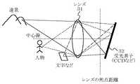
図3はカメラ部30の構成と機能を説明する図である。カメラ部30はレンズ31と受光素子32とを含む。受光素子32としては、CCD(charge coupleddevice)センサーやCMOS(complementary metal−oxide semiconductor)センサー等が用いられる。以下、受光素子32をセンサー32と記す。レンズ31の光軸が受光素子の垂直線に対して傾くようにレンズ31と受光素子32とを取り付ける。
【0019】
レンズ31の焦点距離には、無限遠から到達した光が集まる。カメラでは、一般的に受光素子とレンズの距離を焦点より遠く離すことにより、より近い被写体から発せられた光が結像する。図3のようにレンズ31の光軸(中心線)をセンサー32の垂直線からずらすことにより、センサー32の位置により最適なピントの距離が変化している。この技術は従来より「あおり」、「チルト」などと称されて、風景の手前(画面の下)から奥(画面の上)までピントを合わせる撮影技術としてよく知られているので、詳しい説明は省略する。
【0020】
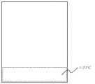
次に、第1の実施の形態の動作について説明する。図4、図5、図6はセンサー32から画像を切り出す概念を示す図である。
【0021】
実際には図3に示すように被写体は反転して結像するが、ここでは、通常のデジタルカメラのように反転して、実際に肉眼で見える向きになっているとする。
【0022】
上記の場合、画面の上側ほど遠方にピントが合い、画面の下側ほど近傍にピントが合う。すなわち遠方の被写体を撮影する際は図4に示すように、制御部50は、画面上部のエリアAを表示ファインダー20に表示するとともに、撮影時の画像もエリアAから取り込む。この際エリアAの外側は表示ファインダー20には表示せず、使用者はピントが遠くに切り替わったように見える。ピントが近いエリアBの扱いについても同様である。さらにエリアCだけを表示ファインダー20に表示し、文字認識、バーコードなどの接写機能として使用することも可能である。
【0023】
エリアA、エリアB、エリアCの切り替えは、使用者がキー操作部10の例えば十字キーを使用して行う。遠方の被写体撮影時にエリアAの外側は表示ファインダー20には表示せずエリアAのみを表示ファインダー20に表示する制御は制御部50が行う。
【0024】
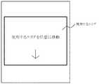
次に、第2の実施の形態について説明する。第1の実施の形態では使用するエリアを、エリアA、エリアB及びエリアCと固定的に割り当てたが、第2の実施の形態では、図7に示すようにエリアの位置を任意に移動する。この移動は、使用者がキー操作部10の例えば十字キーを使用して行う。第1の実施の形態と第2の実施の形態との切り替えも使用者がキー操作部10を使用して行うようにすることができる。
【0025】
次に、第3の実施の形態について説明する。第3の実施の形態では、使用するエリアの面積を第1の実施の形態より小さくする。使用するエリアの面積を小さくすることにより、よりピント距離が均一な画像を得ることが可能となる。従って、文字認識する場合の認識率向上等の効果がある。エリアの面積を小さくすることは、使用者がキー操作部10を操作して指示し、この指示を受けた制御部50が行う。
【0026】
次に、第4の実施の形態について説明する。第4の実施の形態では、使用するエリアの面積を第1の実施の形態より広くする。エリアを広くすることにより、画面の下側はピントが近く、上側はピントが遠い画像を作ることも可能である。一般的な風景などでは手前のものは下側に遠くのものは上側に配置されるので、広くピントが合った画像を得ることが可能である。エリアの面積を広くすることは、使用者がキー操作部10を操作して指示し、この指示を受けた制御部50が行う。
【0027】
第4の実施の形態の応用として、上記のレンズ31とセンサー32を90度横に倒して使用すると画面の左右でピントの距離が異なる画面構成となる。ピントが近いエリアに人物を配置して撮影すれば、人物以外のピントがずれてポートレート撮影が可能となる。カメラ付き携帯電話機を90度傾けて撮影したとき、このような効果が得られる。
【0028】
【発明の効果】
本発明によれば、固定されたレンズとセンサーにより、ピントの距離が異なる撮影を提供することが可能であり、特に昨今の小型化が進む携帯電話機に搭載するカメラにおいて、機構の複雑化を行う必要がなくなるという効果がある。
【図面の簡単な説明】
【図1】カメラ付き携帯電話機の外観図である。
【図2】カメラ付き携帯電話機の構成ブロック図である。
【図3】カメラ部の構成と機能を説明する図である。
【図4】センサーから画像を切り出す概念を示す図である。
【図5】センサーから画像を切り出す概念を示す図である。
【図6】センサーから画像を切り出す概念を示す図である。
【図7】使用するエリアの位置を任意に移動する例を示す図である。
【符号の説明】
10 キー操作部
20 表示ファインダー
30 カメラ部
31 レンズ
32 受光素子
40 メモリ
50 制御部[0001]
TECHNICAL FIELD OF THE INVENTION
The present invention relates to a camera-equipped mobile phone, and more particularly to a small camera-equipped mobile phone with a built-in camera.
[0002]
[Prior art]
In the current mobile phone market, a service that mounts a camera and transmits a captured image by e-mail or the like has become popular. Some mobile phones also provide functions for character recognition and barcode recognition using a camera.
[0003]
However, with the distance between the lens and the light-receiving element that captures the original person or landscape, it is difficult to perform character recognition and image recognition that require close-up photography, and focus is changed by switching the lens of each company or adding an external lens. For adjustment, the mechanism is complicated and restricts miniaturization of the apparatus.
[0004]
A camera that focuses on a plurality of subjects has been proposed (for example, see Patent Document 1).
[0005]
[Patent Document 1]
JP-A-4-1967878
[Problems to be solved by the invention]
As described above, the conventional camera-equipped mobile phone has a problem that the mechanism is complicated and the size of the device is restricted because the focus is adjusted by switching the lens or adding an external lens. . The method proposed in Patent Document 1 also has a similar problem because a drive motor is required.
[0007]
SUMMARY OF THE INVENTION It is an object of the present invention to provide a camera-equipped mobile phone capable of performing character recognition or the like which requires photographing in close proximity to an original person or landscape while maintaining the size of the apparatus.
[0008]
[Means for Solving the Problems]
A camera-equipped mobile phone according to the present invention includes a lens and a light receiving element that receives light passing through the lens, wherein an optical axis of the lens is inclined with respect to a vertical line of the light receiving element.
[0009]
A camera-equipped mobile phone according to the present invention includes a lens and a light receiving element that receives light passing through the lens, and a part that focuses on a distant subject and a part that focuses on a nearby subject occur in the light receiving element. Thus, the optical axis of the lens may be inclined with respect to the vertical line of the light receiving element.
[0010]
The camera-equipped mobile phone of the present invention may be provided with a control unit that changes a range from which an image is cut out from the light receiving element according to a distance of a subject to be photographed.
[0011]
The camera-equipped mobile phone of the present invention may include a finder for projecting an image being photographed, and the control unit may change a projection position on the finder according to a distance of a subject to be photographed.
[0012]
The camera-equipped mobile phone of the present invention may be characterized in that the camera-equipped mobile phone has a key operation unit and a control unit that moves a range from which an image is cut out from the light receiving element in accordance with an input from the key operation unit.
[0013]
The camera-equipped mobile phone of the present invention may include a finder for displaying an image being photographed, and the control unit displays the image cut out from the light receiving element on the finder.
[0014]
The camera-equipped mobile phone of the present invention may be characterized in that the control unit changes an area from which an image is cut out from the light receiving element.
[0015]
BEST MODE FOR CARRYING OUT THE INVENTION
Embodiments of the present invention will be described in detail with reference to the drawings. FIG. 1 is an external view of a camera-equipped mobile phone according to a first embodiment of the present invention. The camera-equipped mobile phone includes a
[0016]
FIG. 2 is a configuration block diagram for explaining the present embodiment. It includes a
[0017]
The
[0018]
FIG. 3 is a diagram illustrating the configuration and functions of the
[0019]
Light that has reached from infinity is collected at the focal length of the
[0020]
Next, the operation of the first embodiment will be described. FIGS. 4, 5 and 6 are views showing the concept of cutting out an image from the
[0021]
Actually, as shown in FIG. 3, the subject is inverted and forms an image. However, here, it is assumed that the subject is inverted like a normal digital camera and is oriented so as to be actually visible to the naked eye.
[0022]
In the above case, the farther the upper side of the screen is, the closer the focus is, and the lower the screen is, the closer the focus is. That is, when photographing a distant subject, the
[0023]
The user switches between the area A, the area B, and the area C by using, for example, a cross key of the
[0024]
Next, a second embodiment will be described. In the first embodiment, the areas to be used are fixedly assigned to the areas A, B, and C. In the second embodiment, the positions of the areas are arbitrarily moved as shown in FIG. . This movement is performed by the user using, for example, a cross key of the
[0025]
Next, a third embodiment will be described. In the third embodiment, the area of the used area is made smaller than that of the first embodiment. By reducing the area of the used area, it is possible to obtain an image with a more uniform focus distance. Therefore, there is an effect of improving the recognition rate in character recognition. The user operates the
[0026]
Next, a fourth embodiment will be described. In the fourth embodiment, the area of the used area is made larger than that of the first embodiment. By widening the area, it is possible to create an image in which the lower side of the screen is closer to the focus and the upper side is far from the focus. In a general scenery or the like, an object in the foreground is arranged on the lower side and an object farther from the lower side is arranged on the upper side, so that an in-focus image can be obtained. The user operates the
[0027]
As an application of the fourth embodiment, when the
[0028]
【The invention's effect】
ADVANTAGE OF THE INVENTION According to this invention, it is possible to provide imaging | photography from which a focus distance differs with a fixed lens and a sensor, Complicate a mechanism especially in the camera mounted in the mobile telephone which is miniaturized recently. This has the effect of eliminating the need.
[Brief description of the drawings]
FIG. 1 is an external view of a camera-equipped mobile phone.
FIG. 2 is a configuration block diagram of a camera-equipped mobile phone.
FIG. 3 is a diagram illustrating a configuration and a function of a camera unit.
FIG. 4 is a diagram showing a concept of cutting out an image from a sensor.
FIG. 5 is a diagram showing a concept of cutting out an image from a sensor.
FIG. 6 is a diagram showing a concept of cutting out an image from a sensor.
FIG. 7 is a diagram illustrating an example in which the position of an area to be used is arbitrarily moved.
[Explanation of symbols]
Claims (7)
Translated fromJapanesePriority Applications (1)
| Application Number | Priority Date | Filing Date | Title |
|---|---|---|---|
| JP2003028328AJP2004240116A (en) | 2003-02-05 | 2003-02-05 | Cellular phone with camera |
Applications Claiming Priority (1)
| Application Number | Priority Date | Filing Date | Title |
|---|---|---|---|
| JP2003028328AJP2004240116A (en) | 2003-02-05 | 2003-02-05 | Cellular phone with camera |
Publications (1)
| Publication Number | Publication Date |
|---|---|
| JP2004240116Atrue JP2004240116A (en) | 2004-08-26 |
Family
ID=32955825
Family Applications (1)
| Application Number | Title | Priority Date | Filing Date |
|---|---|---|---|
| JP2003028328APendingJP2004240116A (en) | 2003-02-05 | 2003-02-05 | Cellular phone with camera |
Country Status (1)
| Country | Link |
|---|---|
| JP (1) | JP2004240116A (en) |
- 2003
- 2003-02-05JPJP2003028328Apatent/JP2004240116A/enactivePending
Similar Documents
| Publication | Publication Date | Title |
|---|---|---|
| KR100870274B1 (en) | Mobile terminal device, controlling device, controlling method, and recording medium having controlling program recorded thereon | |
| CN102404506B (en) | Photographic equipment | |
| JPWO2006033245A1 (en) | Electronics | |
| CN105830424A (en) | Image capture control method and device | |
| KR100593177B1 (en) | Portable terminal camera module with optical zoom | |
| JP2006145812A (en) | Projector device, mobile phone | |
| JP2004254185A (en) | Digital camera | |
| JP2004193860A (en) | Electronics | |
| KR100738803B1 (en) | Camera module and portable terminal that realize dual camera function with one image sensor | |
| KR20040104777A (en) | Handset having dual camera | |
| FI112837B (en) | Mobile station | |
| JP3893958B2 (en) | Mobile device | |
| JP4257508B2 (en) | Electronic camera | |
| CN112468686B (en) | Camera module and mobile terminal having the same | |
| CN112468684B (en) | Camera module and mobile terminal having the same | |
| JP2007116361A (en) | Mobile terminal with camera, and imaging apparatus | |
| JP2005109623A (en) | Multiple-lens imaging apparatus and mobile communication terminal | |
| CN210670246U (en) | Camera module and mobile terminal with same | |
| CN210670245U (en) | Camera module and mobile terminal with the camera module | |
| JP2005109622A (en) | Multiple-lens imaging apparatus and mobile communication terminal | |
| CN210670247U (en) | Camera module and mobile terminal with same | |
| JP2004240116A (en) | Cellular phone with camera | |
| KR20050006623A (en) | Mobile communication terminal comprising magnifiable camera | |
| JP2006072186A (en) | Portable device | |
| KR20090123546A (en) | Imaging optical system having movable optical path switching unit and mobile communication device employing same |
Legal Events
| Date | Code | Title | Description |
|---|---|---|---|
| RD01 | Notification of change of attorney | Free format text:JAPANESE INTERMEDIATE CODE: A7421 Effective date:20050328 | |
| A977 | Report on retrieval | Free format text:JAPANESE INTERMEDIATE CODE: A971007 Effective date:20060421 | |
| A131 | Notification of reasons for refusal | Free format text:JAPANESE INTERMEDIATE CODE: A131 Effective date:20060509 | |
| A521 | Request for written amendment filed | Free format text:JAPANESE INTERMEDIATE CODE: A523 Effective date:20060706 | |
| A02 | Decision of refusal | Free format text:JAPANESE INTERMEDIATE CODE: A02 Effective date:20060926 |