JP2004237697A - Liquid discharging device and the liquid firing method - Google Patents
Liquid discharging device and the liquid firing methodDownload PDFInfo
- Publication number
- JP2004237697A JP2004237697AJP2003032128AJP2003032128AJP2004237697AJP 2004237697 AJP2004237697 AJP 2004237697AJP 2003032128 AJP2003032128 AJP 2003032128AJP 2003032128 AJP2003032128 AJP 2003032128AJP 2004237697 AJP2004237697 AJP 2004237697A
- Authority
- JP
- Japan
- Prior art keywords
- liquid
- ejection
- droplet
- unit
- discharge
- Prior art date
- Legal status (The legal status is an assumption and is not a legal conclusion. Google has not performed a legal analysis and makes no representation as to the accuracy of the status listed.)
- Pending
Links
- 239000007788liquidSubstances0.000titleclaimsabstractdescription351
- 238000000034methodMethods0.000titleclaimsdescription31
- 238000007599dischargingMethods0.000titleclaimsdescription26
- 238000010304firingMethods0.000title1
- 238000012937correctionMethods0.000claimsdescription11
- 238000012545processingMethods0.000claimsdescription8
- 230000001360synchronised effectEffects0.000claims1
- 230000002950deficientEffects0.000abstractdescription8
- 239000000976inkSubstances0.000description145
- 238000010438heat treatmentMethods0.000description42
- 238000007639printingMethods0.000description21
- 238000010586diagramMethods0.000description19
- 230000007547defectEffects0.000description11
- 230000007274generation of a signal involved in cell-cell signalingEffects0.000description7
- 239000000758substrateSubstances0.000description7
- 230000004888barrier functionEffects0.000description6
- 230000015572biosynthetic processEffects0.000description5
- 239000004065semiconductorSubstances0.000description4
- 230000000694effectsEffects0.000description3
- 230000006870functionEffects0.000description3
- PXHVJJICTQNCMI-UHFFFAOYSA-NNickelChemical compound[Ni]PXHVJJICTQNCMI-UHFFFAOYSA-N0.000description2
- 238000007796conventional methodMethods0.000description2
- 230000005484gravityEffects0.000description2
- 238000012423maintenanceMethods0.000description2
- 230000008569processEffects0.000description2
- 238000006467substitution reactionMethods0.000description2
- 238000012935AveragingMethods0.000description1
- 108010076504Protein Sorting SignalsProteins0.000description1
- 238000010521absorption reactionMethods0.000description1
- 230000009471actionEffects0.000description1
- 238000005452bendingMethods0.000description1
- 230000008901benefitEffects0.000description1
- 239000012472biological sampleSubstances0.000description1
- 230000008859changeEffects0.000description1
- 238000004140cleaningMethods0.000description1
- 239000004020conductorSubstances0.000description1
- 238000009792diffusion processMethods0.000description1
- 238000001035dryingMethods0.000description1
- 239000000428dustSubstances0.000description1
- 230000005611electricityEffects0.000description1
- 238000005323electroformingMethods0.000description1
- 238000005516engineering processMethods0.000description1
- 238000010030laminatingMethods0.000description1
- 238000010297mechanical methods and processMethods0.000description1
- 229910052759nickelInorganic materials0.000description1
- 238000000206photolithographyMethods0.000description1
- 229910052710siliconInorganic materials0.000description1
- 239000010703siliconSubstances0.000description1
- 230000002123temporal effectEffects0.000description1
- 238000012360testing methodMethods0.000description1
- 238000012546transferMethods0.000description1
- 230000009466transformationEffects0.000description1
Images


Classifications
- B—PERFORMING OPERATIONS; TRANSPORTING
- B41—PRINTING; LINING MACHINES; TYPEWRITERS; STAMPS
- B41J—TYPEWRITERS; SELECTIVE PRINTING MECHANISMS, i.e. MECHANISMS PRINTING OTHERWISE THAN FROM A FORME; CORRECTION OF TYPOGRAPHICAL ERRORS
- B41J2/00—Typewriters or selective printing mechanisms characterised by the printing or marking process for which they are designed
- B41J2/435—Typewriters or selective printing mechanisms characterised by the printing or marking process for which they are designed characterised by selective application of radiation to a printing material or impression-transfer material
- B41J2/465—Typewriters or selective printing mechanisms characterised by the printing or marking process for which they are designed characterised by selective application of radiation to a printing material or impression-transfer material using masks, e.g. light-switching masks
- A—HUMAN NECESSITIES
- A47—FURNITURE; DOMESTIC ARTICLES OR APPLIANCES; COFFEE MILLS; SPICE MILLS; SUCTION CLEANERS IN GENERAL
- A47K—SANITARY EQUIPMENT NOT OTHERWISE PROVIDED FOR; TOILET ACCESSORIES
- A47K3/00—Baths; Douches; Appurtenances therefor
- A47K3/001—Accessories for baths, not provided for in other subgroups of group A47K3/00 ; Insertions, e.g. for babies; Tubs suspended or inserted in baths; Security or alarm devices; Protecting linings or coverings; Devices for cleaning or disinfecting baths; Bath insulation
- A47K3/004—Trays
- B—PERFORMING OPERATIONS; TRANSPORTING
- B41—PRINTING; LINING MACHINES; TYPEWRITERS; STAMPS
- B41J—TYPEWRITERS; SELECTIVE PRINTING MECHANISMS, i.e. MECHANISMS PRINTING OTHERWISE THAN FROM A FORME; CORRECTION OF TYPOGRAPHICAL ERRORS
- B41J2/00—Typewriters or selective printing mechanisms characterised by the printing or marking process for which they are designed
- B41J2/005—Typewriters or selective printing mechanisms characterised by the printing or marking process for which they are designed characterised by bringing liquid or particles selectively into contact with a printing material
- B41J2/01—Ink jet
- B41J2/135—Nozzles
- B41J2/145—Arrangement thereof
- B41J2/155—Arrangement thereof for line printing
Landscapes
- Health & Medical Sciences (AREA)
- Public Health (AREA)
- Epidemiology (AREA)
- General Health & Medical Sciences (AREA)
- Particle Formation And Scattering Control In Inkjet Printers (AREA)
- Ink Jet (AREA)
Abstract
Description
Translated fromJapanese【0001】
【発明の属する技術分野】
本発明は、液滴の吐出方向を複数の方向に偏向可能な液体吐出部を備える液体吐出装置及び液体吐出方法に関する。詳しくは、液滴の吐出不良となった液体吐出部が存在するときに、その液体吐出部からの液滴の吐出を停止するとともに他の液体吐出部が液滴の吐出を代行できるようにした技術に係るものである。
【0002】
【従来の技術】
従来の液体吐出装置の1つであるインクジェットプリンタにおいては、通常、ノズルを有する液体吐出部が直線状に配列されたヘッドを備えている。そして、このヘッドの各液体吐出部から、微少なインク液滴をノズル面に対向して配置される印画紙等の記録媒体に向けて順次吐出することにより、画素領域に所定数のドットを配置し、画素を形成している。
【0003】
ここで、液体吐出部が液滴を正常に吐出できなくなる場合があり、その理由としては、種々のことが考えられる。
その1つとして、液体吐出部のノズルの液滴出口付近に粉塵が付着することによる吐出不良がある。この場合の解決方法として、ヘッドクリーニングを行う方法が知られている。
【0004】
また第2に、液体吐出部に詰まりが生じたり、液体吐出部内に設けられているエネルギー発生素子(例えば、サーマル方式の場合には発熱素子)の断線等による吐出不良がある。この場合には、十分な解決方法はなく、ヘッド交換等により対処するのが通常である。
【0005】
ところで、インクジェットプリンタでは、ヘッドが印画紙の送り方向に対して垂直な方向に往復移動し、この往復移動中に印画を行うとともに、印画紙が上記往復移動方向と略垂直な方向に搬送されるシリアル方式の他に、印画紙の全幅にわたるようにヘッドを形成し、印画紙を送り方向に搬送しつつ印画を行うライン方式とが知られている。
【0006】
特に、ライン方式のインクジェットプリンタとしては、小さなヘッドチップを、端部同士が繋がるように複数並設して、それぞれのヘッドチップに適当な信号処理を行うことによって、印画する段階で、印画紙の全幅に繋がった記録を行うようにすることが知られている(例えば、特許文献1参照)。
【0007】
また、シリアル方式のインクジェットプリンタにおいて、中間階調を表現すること等の目的で、重ね打ちによる方法が知られている。
これは、1つの画素領域に対して、何度もインク液滴(ドット)を重ねていき、液体吐出部の特性を平均化する方法である。そして、先に配列したドット列の隙間を埋めるように重ねてドットを配列することで、隙間を埋めるようにするものである。
【0008】
このような重ね打ちを採用することにより、多少、特性の悪い液体吐出部、あるいは全く液滴を吐出できない液体吐出部が一部に存在したとしても、全体の印画結果では、その一部の液体吐出部の欠陥を目立たないようにすることができる。
【0009】
【特許文献1】
特開2002−36522号公報
【0010】
【発明が解決しようとする課題】
しかし、ライン方式のインクジェットプリンタでは、印画紙の送り方向に垂直な方向にヘッドが往復移動しない、すなわち一旦記録した領域を、再度記録することにより重ね打ちを行うことはできない。
よって、ライン方式では、液体吐出部固有のばらつきが液体吐出部の並び方向に存在すると、それがスジムラとして目立ってしまう場合があるという問題がある。
【0011】
さらに、液滴を吐出することができない液体吐出部が1個でも存在すると、その液体吐出部が本体形成すべき画素列には、画素が全く形成されずに白スジが発生してしまう。特に、高画質が要求される写真画やグラフィック等になると、その欠陥は顕著に現れてしまうという問題がある。
なお、ライン方式のインクジェットプリンタにおいて、印画紙の送り方向にドットを重ねるように打つことによって、その階調度を増やすことは可能であるが、その重ね打ちは、階調度を上げることのみの効果があり、上記のような重ね打ちにおける平均化には寄与しない。
【0012】
したがって、本発明が解決しようとする課題は、本件発明者らによって既に提案されている、インク液滴を偏向吐出できる技術(例えば特願2002−161928、特願2002−320861、及び特願2002−320862)を用いて、液滴を吐出できない液体吐出部が一部に存在したとしても、その欠陥を補うことができるようにすることである。
【0013】
【課題を解決するための手段】
本発明は、以下の解決手段によって、上述の課題を解決する。
本発明の1つである請求項1に記載の発明は、ノズルを有する液体吐出部を特定方向に複数並設したヘッドを備え、液滴を着弾させる液滴着弾対象物と前記ヘッドとを前記特定方向に略垂直な方向に相対移動させるとともに、その相対移動中に前記液体吐出部から所定数の液滴を吐出し、画素領域に所定数のドットからなる画素を形成する液体吐出装置であって、前記液体吐出部は、液滴の吐出方向を前記特定方向において複数の方向に偏向可能であり、近隣に位置する少なくとも2つの前記液体吐出部は、少なくとも1つの同一画素領域に液滴を着弾させることが可能であり、複数の前記液体吐出部のうち、液滴の吐出不良により吐出を停止する前記液体吐出部に関する情報を記憶する吐出停止情報記憶手段と、前記吐出停止情報記憶手段に記憶された情報に基づいて、液滴の吐出を停止する前記液体吐出部が本来受け持つ液滴の吐出信号の少なくとも一部を、液滴の吐出を停止する前記液体吐出部の近隣に位置する少なくとも1つの他の前記液体吐出部に移すとともに、液滴の吐出を停止する前記液体吐出部が前記吐出信号に従って液滴を吐出したときの液滴の着弾位置に、その少なくとも1つの他の前記液体吐出部から吐出した液滴を着弾させるように制御する液滴吐出代行手段とを備えることを特徴とする。
【0014】
(作用)
上記発明においては、液体吐出部から吐出される液滴の吐出方向を、複数の方向に偏向可能なように形成されている。また、近隣に位置する少なくとも2つの液体吐出部、例えば特定方向において連続(隣接)する2つの液体吐出部は、少なくとも1つの同一画素領域に液滴を着弾させることが可能に形成されている。
【0015】
さらにまた、液滴の吐出不良により吐出を停止する液体吐出部が存在するときには、その情報が吐出停止情報記憶手段に記憶される。
そして、その記憶された情報に基づいて、吐出を停止する液体吐出部が本来受け持つ液滴の吐出信号の少なくとも一部が、その近隣に位置する少なくとも1つの他の液体吐出部に移され、その液体吐出部によって、液滴が代行吐出され、吐出を停止する液体吐出部が液滴を吐出したときの着弾位置に、液滴が着弾される。
【0016】
したがって、液滴の吐出を停止する液体吐出部が存在しても(吐出不良となった液体吐出部が発生しても)、他の液体吐出部により液滴を代行吐出することで、その欠陥を補うことができる。
【0017】
【発明の実施の形態】
以下、図面等を参照して、本発明の一実施形態について説明する。なお、本明細書において、「液滴」とは、後述する液体吐出部のノズル18から吐出される微少量(例えば数ピコリットル程度)の液体(本実施形態ではインク)をいう。また、「ドット」とは、液滴が印画紙等の記録媒体(液滴着弾対象物)に着弾して形成されたものをいう。さらにまた、「画素」とは、画像の最小単位をいい、「画素領域」とは、画素を形成するための領域となるものをいう。
【0018】
そして、1つの画素領域に、所定数(0個、1個又は複数個)の液滴が着弾し、ドット無しの画素(1階調)、1つのドットからなる画素(2階調)、又は複数のドットからなる画素(3階調以上)が形成される。これらの画素が記録媒体上に多数配列されることで、画像を形成する。
なお、画素に対応するドットは、その画素領域内に完全に入るものではなく、画素領域からはみ出す場合もある。
【0019】
以下に、本発明による液体吐出装置の一実施形態を示す。
本実施形態の液体吐出装置は、液滴を吐出するためのラインヘッドを備える。
さらにこのラインヘッドは、複数の液体吐出部を記録媒体の幅方向(記録媒体の搬送方向に対して垂直な方向)に並設したものである。
さらにまた、液体吐出部は、
(1)吐出すべき液滴を収容する液室(以下の実施形態では、インク液室12に該当)と、
(2)液室中の液体にエネルギーを付与するエネルギー発生素子(以下の実施形態では、発熱抵抗体13に該当)と、
(3)エネルギー発生素子により、前記液室内の液体を吐出するノズル(吐出口)を形成したノズルシート(吐出口形成部材)と
を備えるものである。
【0020】
そして、エネルギー発生素子による液体へのエネルギーの付与の仕方を制御することで、ノズルから吐出される液滴の吐出方向を、液体吐出部の並び方向において複数方向に偏向させるものである。例えば、エネルギー発生素子は、液室の一面の少なくとも一部の領域に配置され、そのエネルギー発生素子上のエネルギー分布を制御する、例えばエネルギー発生素子上の1の領域と他の1の領域とのエネルギーの与え方に差異を設けるか、又はネルギー発生素子上の1の領域と他の1の領域とのエネルギー分布に差異を設けること等によって、エネルギー分布を制御する。なお、本発明に用いられる液体吐出装置は、本実施形態に限定されるものではない。
【0021】
図1は、本発明による液体吐出装置を適用したインクジェットプリンタ(以下、単に「プリンタ」という。)のヘッド11を示す分解斜視図である。図1において、ノズルシート17は、バリア層16上に貼り合わされるが、このノズルシート17を分解して図示している。
ヘッド11において、基板部材14は、シリコン等からなる半導体基板15と、この半導体基板15の一方の面に析出形成された発熱抵抗体13とを備えるものである。発熱抵抗体13は、半導体基板15上に形成された導体部(図示せず)を介して外部回路と電気的に接続されている。
【0022】
また、バリア層16は、例えば、感光性環化ゴムレジストや露光硬化型のドライフィルムレジストからなり、半導体基板15の発熱抵抗体13が形成された面の全体に積層された後、フォトリソプロセスによって不要な部分が除去されることにより形成されている。
さらにまた、ノズルシート17は、複数のノズル18が形成されたものであり、例えば、ニッケルによる電鋳技術により形成され、ノズル18の位置が発熱抵抗体13の位置と合うように、すなわちノズル18が発熱抵抗体13に対向するようにバリア層16の上に貼り合わされている。
【0023】
インク液室12は、発熱抵抗体13を囲むように、基板部材14とバリア層16とノズルシート17とから構成されたものである。すなわち、基板部材14は、図中、インク液室12の底壁を構成し、バリア層16は、インク液室12の側壁を構成し、ノズルシート17は、インク液室12の天壁を構成する。これにより、インク液室12は、図1中、右側前方面に開口領域有し、この開口領域とインク流路(図示せず)とが連通される。
【0024】
上記の1個のヘッド11には、通常、100個単位の規模で、インク液室12と、各インク液室12内にそれぞれ配置された発熱抵抗体13とを備え、プリンタの制御部からの指令によってこれら発熱抵抗体13のそれぞれを一意に選択して発熱抵抗体13に対応するインク液室12内のインクを、インク液室12に対向するノズル18から吐出させることができる。
【0025】
すなわち、ヘッド11と結合されたインクタンク(図示せず)から、インク液室12にインクが満たされる。そして、発熱抵抗体13に短時間、例えば、1〜3μsecの間パルス電流を流すことにより、発熱抵抗体13が急速に加熱され、その結果、発熱抵抗体13と接する部分に気相のインク気泡が発生し、そのインク気泡の膨張によってある体積のインクが押しのけられる(インクが沸騰する)。これによって、ノズル18に接する部分の上記押しのけられたインクと同等の体積のインクがインク液滴としてノズル18から吐出され、印画紙上に着弾され、ドットが形成される。
【0026】
さらに本実施形態では、複数のヘッド11を記録媒体の幅方向に並べて、ラインヘッドを形成している。図2は、ラインヘッド10の実施形態を示す平面図である。図2では、4つのヘッド11(「N−1」、「N」、「N+1」及び「N+2」)を図示している。ラインヘッド10を形成する場合には、図1中、ヘッド11のノズルシート17を除く部分(ヘッドチップ)を複数並設する。そして、これらのヘッドチップの上部に、全てのヘッドチップの各液体吐出部に対応する位置にノズル18が形成された1枚のノズルシート17を貼り合わせることにより、ラインヘッド10を形成する。
【0027】
ここで、隣接するヘッド11の各端部にあるノズル間ピッチ、すなわち図2中、A部詳細図において、N番目のヘッド11の右端部にあるノズル18と、N+1番目のヘッド11の左端部にあるノズル18との間の間隔は、ヘッド11のノズル18間の間隔に等しくなるように、各ヘッド11が配置される。
【0028】
さらに、複数のラインヘッド10を所定間隙を介して平行に配置し、各ラインヘッド10ごとに異なる色のインクを供給するようにすれば、カラーラインヘッドを構成することができる。
【0029】
続いて、本実施形態の液体吐出部をより詳細に説明する。
図3は、ヘッド11の液体吐出部をより詳細に示す平面図及び側面の断面図である。図3の平面図では、ノズル18を1点鎖線で図示している。
図3に示すように、本実施形態のヘッド11では、1つのインク液室12内に、2つに分割された発熱抵抗体13が並設されている。さらに、分割された2つの発熱抵抗体13の並び方向は、ノズル18の並び方向(図3中、左右方向)である。
【0030】
このように、1つのインク液室12内に2つに分割された発熱抵抗体13を備えた場合には、各々の発熱抵抗体13がインクを沸騰させる温度に到達するまでの時間(気泡発生時間)を同時にしたときには、2つの発熱抵抗体13上で同時にインクが沸騰し、インク液滴は、ノズル18の中心軸方向に吐出される。
これに対し、2つの分割した発熱抵抗体13の気泡発生時間に時間差を与えれば、2つの発熱抵抗体13上で同時にインクが沸騰しない。これにより、インク液滴の吐出方向は、ノズル18の中心軸方向からずれ、偏向して吐出される。これにより、偏向なくインク液滴が吐出されたときの着弾位置からずれた位置にインク液滴を着弾させることができる。
【0031】
図4は、2分割した発熱抵抗体13のインクの気泡発生時間差として、2分割した発熱抵抗体13間の電流量の差、すなわち、偏向電流を横軸にとるとともに、インクの着弾位置での偏向量(ノズル18の中心軸を記録媒体のインク液滴の着弾面に延長したときのノズル18の中心軸と記録媒体との交点からのずれ量)を縦軸にした場合の実測値データである。図4では、発熱抵抗体13の主電流を80mAとして、片方の発熱抵抗体13に前記偏向電流を重畳し、インクの偏向吐出を行った。また、ノズル18の先端からインク液滴の着弾位置までの距離を2mmとした。
【0032】
このように、2分割した各発熱抵抗体13に流す電流量を変え、偏向電流を大きくするほど、2つの発熱抵抗体13上の気泡発生時間の時間差が大きくなり、この時間差に応じて偏向量を大きくし、偏向なくインク液滴が吐出されたときの着弾位置からずらすことができる。
【0033】
なお、本実施形態では、2分割した発熱抵抗体13によって、インク液室12内の下面領域のエネルギー発生分布を異ならせるようにしたが、これに限らず、例えばインク液室12内の下面領域には1つの発熱抵抗体13を設け、その発熱抵抗体13の領域内における一部の領域と、他の一部の領域とで発生する熱エネルギーが異なるようにすることで、インク液室12内の下面領域のエネルギー発生分布を異ならせ、それによってインク液室12内における一部の領域と他の一部の領域とで気泡発生時間差が生じるようにし、インク液滴が偏向して吐出されるように制御しても良い。
【0034】
以上説明した構成を用いて、本発明は、近隣に位置する少なくとも2つの液体吐出部は、少なくとも1つの同一画素領域に液滴を着弾させることが可能に形成されている。特に、液体吐出部の並び方向における並設ピッチをPとしたとき、各液体吐出部は、自己の液体吐出部の中心位置に対して、ノズル18の並び方向において、
(式1)±(1/2×P)×N(ここで、Nは、正の整数)
の位置に液滴を着弾させることが可能に形成されている。
【0035】
図5は、並設された液体吐出部のノズル18と、インク液滴の着弾位置(ドットの形成位置)との関係を説明する正面図である。
図5では、1つの同一画素領域に、隣接する2つの液体吐出部のノズル18から吐出されたインク液滴が着弾できるようにしたものである。
【0036】
図5中、例えばノズルNは、画素領域nと画素領域n+1とにそれぞれインク液滴を着弾させることができる。ここで、ノズルNの中心軸を記録媒体(インク液滴の着弾位置)にまで延長したときのノズルNの中心軸と記録媒体との交点は、画素領域nと画素領域n+1との中点と一致する。
また、ノズルN+1は、画素領域n+1と画素領域n+2とにそれぞれインク液滴を着弾させることができる。
【0037】
これにより、画素領域n+1に対しては、ノズルNからインク液滴を図5中、右方向に偏向して吐出してドットを形成することができ、あるいは、ノズルN+1からインク液滴を図5中、左側に偏向して吐出してドットを形成することもできる。
他のノズル18と画素領域との関係についても同様である。
【0038】
図5では、各液体吐出部のノズル18は、自己の液体吐出部のノズル18の中心位置に対して、ノズル18の並び方向において、
±(1/2×P)×1
の位置に液滴を着弾させることが可能に形成されている。すなわち、上記の式1のN=1の場合に相当する。
例えば、600[DPI]の場合には、ノズルピッチは42.33[μm]であるので、着弾位置での偏向量は、片側で21.15[μm]となる。
【0039】
図6は、図5と異なる例を示すものである。図6では、1つの同一画素領域に、近隣に位置する3つの液体吐出部のノズル18から吐出されたインク液滴が着弾できるようにしたものである。
図6中、隣接する3つの液体吐出部のノズル18をそれぞれノズルN、N+1、及びN+2とし、ノズルNからインク液滴が記録媒体に対して垂直に(すなわち、ノズルNの中心軸に一致する方向に)吐出されたときのインク液滴の着弾位置に対応する画素領域を画素領域nとし、その左側及び右側の画素領域をそれぞれ画素領域n−1、及びn+1とする。
【0040】
このとき、ノズルN+1から、インク液滴を記録媒体に対して垂直に吐出して、画素領域n+1にインク液滴を着弾させることができる。
また、ノズルNから、図6中、インク液滴を右側に偏向して吐出して、画素領域n+1にインク液滴を着弾させることもできる。
さらにまた、ノズルN+2から、図6中、インク液滴を左側に偏向して吐出して、画素領域n+1にインク液滴を着弾させることもできる。
他のノズル18と画素領域との関係についても同様である。
【0041】
したがって、図6では、各液体吐出部のノズル18は、自己の液体吐出部のノズル18の中心位置に対して、ノズル18の並び方向において、
±(1/2×P)×2
の位置に液滴を着弾させることが可能に形成されている。すなわち、上記の式1のN=2の場合に相当する。
【0042】
さらに本発明は、印画紙の送り方向(ヘッド11と印画紙との相対移動方向)におけるドット列を形成するための液滴の吐出信号を、その吐出信号に対応する液滴の着弾位置に液滴を着弾可能な少なくとも2つの液体吐出部に順次分配し、その少なくとも2つの液体吐出部からそれぞれ分配された吐出信号に従って所定方向に液滴を吐出することにより、ドット列を形成するものである。
図7は、この制御方法を説明する図であり、図5に示す偏向吐出機能を有する液体吐出部の例である。すなわち、上記の式1において、N=1の場合に相当するものを例に挙げている。
【0043】
図7中、各液体吐出部のノズル18を並び方向に順に、ノズルN、N+1、N+2、・・とする。また、各ノズルN、N+1、・・の真下に配置されるドット列をそれぞれドット列n、n+1、・・とし、これらのドット列n、n+1、・・に対応する吐出信号をそれぞれ吐出信号S、S+1、・・とする。
【0044】
図7において、1つの画素に対応するドット列を形成するために、それぞれそのドット列に対応する吐出信号が入力される。吐出信号は、それぞれドット列のドットごとの吐出命令(図7中、吐出信号内の丸印で示すもの)から構成されている信号列である。
【0045】
また、図7中、吐出信号のマス(スロット)は、その時間的配列を示したものであり、丸印(吐出命令)が存在する時点(タイミング)で、液体吐出部のノズル18からインク液滴が吐出されることを示している。また、マスのピッチは、各液体吐出部のノズル18からの吐出サイクルを示している。本実施形態では、64個の液体吐出部を1ブロックとして取り扱い、共通する制御を行っている。また、吐出信号のマスのピッチ(1つのマスの時間帯)は、1.5×64=96(μ秒)であり、マス中の丸印は、1.5(μ秒)間だけロジック出力が「1」になるような吐出命令であり、その1.5(μ秒)間、発熱抵抗体13に電流が流される。
【0046】
このとき、例えば吐出信号Sの各吐出命令は、交互にノズル(液体吐出部)NとN+1に分配される。すなわち、吐出信号Sの最初の吐出命令(図7中、最下部に位置する吐出命令)は、ノズルN+1に入力され、ノズルN+1から、図中、左方向にインク液滴が偏向吐出されて、ドット列nにインク液滴が着弾する。次の吐出命令は、ノズルNに入力され、ノズルNから、図中、右方向にインク液滴が偏向吐出されて、ドット列nにインク液滴が着弾する。
【0047】
このようにして、1つの吐出信号Sに対し、ノズルNとN+1とに交互にその吐出命令が順次分配されるとともに、所定方向にインク液滴が吐出され、最終的には、その吐出信号Sに対応するドット列nが形成される。
したがって、1つの吐出信号の各吐出命令が複数の液体吐出部に順次分配されるとともに、所定方向にインク液滴が吐出され、最終的には、その吐出信号に対応するドット列が形成される。
【0048】
また、図8は、図7と同様の制御方法を説明する図であり、図6に示す偏向吐出機能を有する液体吐出部の例である。すなわち、上記の式1において、N=2の場合に相当するものを例に挙げている。
【0049】
図8において、吐出信号S+1、ノズルN+1、及びドット列n+1に着目すると、吐出信号S+1の最初の吐出命令(図8中、最下部に位置する吐出命令)は、ノズルN+2に入力され、ノズルN+2から、図中、左方向にインク液滴が偏向吐出されて、ドット列n+1にインク液滴が着弾する。次の吐出命令は、ノズルN+1に入力され、ノズルN+1から、インク液滴が偏向されることなく(真下に)吐出されて、ドット列n+1にインク液滴が着弾する。さらに次の吐出命令は、ノズルNに入力され、ノズルNから、図中、右方向にインク液滴が偏向吐出されて、ドット列n+1にインク液滴が着弾する。
【0050】
なお、以上の吐出命令の分配は、一形態を示すものであり、吐出信号の各吐出命令の分配方法には、種々の形態が考えられる。例えば、吐出信号の1番目と2番目の吐出命令を1つの(同一の)液体吐出部に分配し、3番目と4番目の吐出命令を他の(同一の)液体吐出部に分配する、・・という方法であっても良い。
【0051】
図9は、図7の例において、液体吐出部の選択、偏向方向、及び偏向振幅の制御を説明する図である。
液体吐出部が並設されたヘッド11には、全ての液体吐出部の回路に共通して制御されるスイッチA及びB、並びに制御端子Cが設けられている。
スイッチAは、液体吐出部を選択するためのものであり、吐出信号の吐出命令を、いずれの液体吐出部に入力するかを決定するためのスイッチである。例えば、スイッチAの切替えにより、全ての液体吐出部を同時に同方向に切り替えることができる。例えば図9に示すように切り替えられているときには、吐出信号S+1は、ノズルNに入力される。
【0052】
また、インク液滴の偏向方向を切り替えるためのスイッチBは、インク液滴を、図中、左方向又は右方向のいずれに偏向させるかを切り替えるためのスイッチであり、スイッチBによって、全ての液体吐出部の偏向方向が同時に同方向に切替えられる。
【0053】
そして、スイッチAとBとは、一致して動作される。例えば、図9に示すようにスイッチAが切り替えられているときには、吐出信号S+1の吐出命令は、ノズルNに入力されるが、このときのスイッチBは、図中、右方向に液滴を偏向吐出させるように液体吐出部を制御する。これにより、ノズルNからインク液滴が図中、右側に偏向吐出され、ドット列n+1の1ドットを形成する。
【0054】
さらにまた、制御端子Cは、図4に示す特性の範囲で、アナログ的に偏向振幅を制御するための端子である。この制御端子Cに適当な電圧が印加されると、発熱抵抗体13に所定値の電流が流れる。これにより、印加する電圧を変えることで、発熱抵抗体13に流す電流(偏向電流)を制御することで、液滴の偏向量(着弾位置)を制御することができる。
【0055】
続いて、液体吐出部に液滴の吐出不良が生じたときの、他の液体吐出部による液滴の代行吐出制御(液滴吐出代行手段)について説明する。
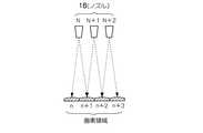
図10は、図9において、代行吐出制御を可能とした場合のシステム概念を示す図である。
図10において、スイッチA1は、図9のスイッチAと同様のものである。さらに図10では、各液体吐出部ごとに個別に設定するスイッチA2が設けられている。スイッチA2がオンにされると、図9と同様に、吐出信号の吐出命令がその液体吐出部に入力されるが、オフにされると、吐出信号の吐出命令がその液体吐出部に送られることはない。
その他のスイッチBや制御端子Cは、図9のものと同様である。
【0056】
インク液滴の吐出不良(インク液滴を全く吐出できないもの、及びインク液滴をほとんど吐出できないものを含む)により、吐出を停止する液体吐出部であるか否かの特定においては、例えば以下の方法が挙げられる。
例えば第1に、適当なテストパターンを印画し、そのパターンと正常なパターンとを対比し、正常なパターンが正しく印画されていなければ吐出不良と認定する方法が挙げられる。なお、この方法は、目視により判断することとなる。
【0057】
また第2に、機械的に行う方法として、吐出するインク液滴を帯電させ、そのインク液滴を特定の絶縁された電極に滴下させて電気量の変化によりその液体吐出部からのインク液滴の吐出が正常であるか否かを判定する方法が挙げられる。このように、インク液滴の吐出不良が存在する液体吐出部の特定方法としては、種々の方法が挙げられる。
【0058】
そして、吐出不良でない(正常な)液体吐出部については、スイッチA2をオンにするが、吐出不良と判定された液体吐出部については、液滴の吐出を停止するため、スイッチA2をオフにする。図10の例では、ノズルN+1に対応するスイッチA2がオフにされている状態を図示している(ノズルN+1以外のノズルに対応するスイッチA2はオンである)。
【0059】
なお、具体的な回路としては、吐出命令の入力時(1.5μ秒間)に「1」になり、それ以外は「0」となる第1入力端子と、スイッチA2がオンのときは「1」となり、オフのときは「0」となる第2入力端子とを備えたANDゲートを用い、その出力が液体吐出部に入力されるようにする。これにより、スイッチA2がオフであるとき(吐出不良のとき)は、吐出命令が液体吐出部に入力されることはない。
【0060】
また、ヘッド11中の液体吐出部のうち、インク液滴の吐出不良により吐出を停止する液体吐出部に関する情報(吐出を停止する液体吐出部の番号等)をメモリに記憶しておき(吐出停止情報記憶手段)、例えば電源投入時にその情報を読み出し、スイッチA2を制御すれば良い。
【0061】
次に、吐出信号の制御について説明する。
吐出を停止する情報が存在するとき、すなわち上述の吐出停止情報記憶手段に、吐出を停止する液体吐出部の情報が記憶されているときには、その液体吐出部が本来受け持つ吐出信号を、吐出を停止する液体吐出部の近隣に位置する少なくとも1つの他の液体吐出部、特に本実施形態では両隣の液体吐出部に移すとともに、その両隣の液体吐出部を用いて、インク液滴の代行吐出を行うように制御する。この場合、その液体吐出部におけるインク液滴を吐出しない空き時間帯に移すように制御する。
【0062】
図10の例では、吐出を停止する液体吐出部のノズルは、ノズルN+1である。この液体吐出部が本来受け持つ吐出信号は、吐出信号S+1、及びS+2である。このため、吐出信号S+1については、ノズルNからインク液滴を吐出して、吐出信号S+1に対応するドット列n+1を形成するように制御する。また、吐出信号S+2については、ノズルN+2から液滴を吐出して、吐出信号S+2に対応するドット列n+2を形成するように制御する。
【0063】
ここで、本実施形態では、インク液滴の吐出信号の生成において、インク液滴の吐出を停止する液体吐出部が関与しない通常モードの吐出信号と、インク液滴の吐出を停止する液体吐出部が関与する吐出信号であって吐出を停止する液体吐出部の両隣に位置する他の液体吐出部に吐出信号を移すための補正モードの吐出信号とを、それぞれ生成するように制御する。
【0064】
図10においては、吐出信号S、S+3、及びS+4は、それぞれインク液滴の吐出を停止する液体吐出部(ノズルN+1)が関与しない(すなわち、インク液滴の吐出を停止する液体吐出部に入力されない)吐出信号であるので、この場合には、これらの吐出信号としては、通常モードの吐出信号が生成され、所定の液体吐出部に入力される。
【0065】
これに対し、吐出信号S+1、及びS+2は、それぞれインク液滴の吐出を停止する液体吐出部(ノズルN+1)が関与する(すなわち、インク液滴の吐出を停止する液体吐出部に入力される)吐出信号であるので、この場合には、これらの吐出信号としては、補正モードの吐出信号が生成される。
【0066】
補正モードの吐出信号は、1の吐出命令の時間帯が通常モードの吐出信号における吐出命令の時間帯を2倍に延長したものである。
図10では、補正モードの吐出信号である吐出信号S+1、及びS+2の各マスは、他の吐出信号のマスの2倍の長さとなっている。
このため、例えば吐出信号S+1を例にとると、最初の吐出命令(図中、最下部の丸印で示す吐出命令)は、通常モードの2マス分の時間帯に存在する。
【0067】
そして、液体吐出部を選択するためのスイッチA1は、ノズルNとN+1側に交互に切り替えられるので、吐出信号S+1は、ノズルNとN+1側に交互に入力される。ここで、ノズルNのスイッチA2はオン(接続)であるが、ノズルN+1のスイッチA2は、オフ(切断)である。このため、ノズルN+1に吐出信号S+1の吐出命令が入力されたとしても、その吐出命令に従いインク液滴が吐出されることはない(ノズルN+1に係る液体吐出部が駆動しない)。
【0068】
これに対し、ノズルNに吐出信号S+1の吐出命令が入力されると、その吐出命令に従いインク液滴が吐出される。
そして、上述のように、吐出信号S+1では、1の吐出命令の時間帯が通常モードの2倍に設定されているので、吐出信号S+1の各吐出命令は、全て、ノズルNとN+1との双方に入力される。これにより、ノズルN+1からは、吐出信号S+1の吐出命令に対応するインク液滴は吐出されないが、ノズルNからは、吐出信号S+1の吐出命令に対応するインク液滴が吐出される。この結果、ノズルNからは、吐出信号S+1の全ての吐出命令に対応するインク液滴が吐出されることとなる。
【0069】
したがって、ノズルNには、吐出信号Sの吐出命令の一部が入力されるとともに(他の一部は、ノズルN−1(点線で示す)に入力される)、吐出信号S+1の全ての吐出命令が入力される。
【0070】
そして、吐出信号Sの吐出命令がノズルNに入力されたときは、スイッチBの制御により、ノズルNの中心軸からノズルピッチの1/2だけ着弾位置が図中、左側にずれるように液滴が偏向吐出される。これにより、吐出信号Sの吐出命令に基づいて、ノズルNから吐出されたインク液滴により、ドット列nを構成するドットが形成される。
【0071】
一方、吐出信号S+1の吐出命令がノズルNに入力されたときは、スイッチBの制御により、ノズルNの中心軸からノズルピッチの1/2だけ着弾位置が図中、右側にずれるようにインク液滴が偏向吐出される。これにより、吐出信号S+1の吐出命令に基づいて、ノズルNから吐出されたインク液滴により、ドット列n+1の全てのドットが形成される。
なお、上述したように、吐出信号S+1の吐出命令は、ノズルNに入力されるとともに、ノズルN+1にも入力されるが、スイッチA2がオフであるため、ノズルN+1からインク液滴が吐出され、ドット列n+1のドットを形成することはない。
【0072】
以上のように制御することにより、インク液滴を吐出しない液体吐出部(ノズル18)が存在するときには、その液体吐出部の近隣の他の液体吐出部に、インク液滴を吐出しない液体吐出部が本来受け持つ吐出信号を移して、他の液体吐出部からインク液滴を代行して吐出するようにしたので、ヘッド11内において、インク液滴の吐出不良が発生してインク液滴を吐出しない液体吐出部が一部に存在しても、その液体吐出部の影響を受けないようにすることができる。
【0073】
また、図10では、1つの吐出信号の総時間帯として、通常モードでは16マスを採っている。これにより、補正モードでは、各マスが通常モードの2倍の時間帯となるため、補正モードの吐出信号の総時間帯は、8マスとなる。
ここで、本実施形態のようにプリンタに適用した場合に、印画紙の1画素当たりのインク液滴の吸収量は、画質の維持や乾燥時間等を考慮すると、5〜6滴である(1液滴の平均体積が約4.5ピコリットルとした場合)。また、吐出信号の信号処理において、効率の良いバイナリー数を用いると、3ビット(8マス)となる。よって、1画素当たりの最大吐出命令数と信号処理とを考慮して、本実施形態では、上記のような構成としている。
【0074】
また、例えば8マスに対して、1画素当たりの最大吐出命令数を6としたとき、代行吐出時の最大吐出命令数も6となるので、補正モードの吐出信号を併せて処理するためには、通常モードの吐出信号の1.5倍の時間が必要となる。
さらにまた、吐出命令数が最大に近い(例えば5〜6)場合は、最高濃度に近く、γ(ガンマ)特性もかなり緩やかなものとなる。このため、補正モードでは、例えば4つの吐出命令数までを代行吐出の対象とすれば、新たな時間帯を付加する必要なく、通常の信号処理システムで対応することができ、印画速度の低下もなくすことができる。
【0075】
よって、補正モードの吐出信号の生成においては、全ての吐出命令を代行するようにしても良いが、印画速度の維持を優先するのであれば、その一部のみの吐出命令について代行吐出するようにしても良い。これらのいずれを採用するかは、任意である。
また、印画速度を落としても全ての吐出命令を代行する「画質優先モード」と、印画速度を維持して一部の吐出命令のみについて代行吐出を行う「速度優先モード」との双方を予め準備しておき、いずれかを選択可能としたり、あるいは画像の内容等に応じて切り替えて使用することも可能である。
【0076】
また、液体吐出部が代行吐出を行う場合には、その分、印画速度を通常時より落とすか、又は液体吐出部の動作速度を速めることが考えられる。
ここで、インク液滴の吐出後にインク液室12内にインクを補填するために必要なリフィル時間を考えると、後者の場合には、その実現が困難である。このため、本発明では、代行吐出を行う場合に、通常モードの吐出信号の処理時間以上に長い時間を要するときは、印画速度を落とすことにより対処する。
【0077】
そして、ヘッド11と印画紙との相対速度を落とす場合には、代行吐出を行わない場合の画素の形成周期(1つの画素を形成するための時間)と、代行吐出を行う場合の画素の形成周期との比として、
Q=(新しい画素の形成周期/元の画素の形成周期)
を設定し、上記の相対速度を、1/Qとなるように制御すれば良い。
このようにすれば、印画された画像のサイズや縦横比を一定にしつつ、代行吐出を行うことができる。
【0078】
図11は、以上のようにして、インク液滴の代行吐出を行うときのハードウェア上の制御の概略を説明する図である。図11では、従来の方式での制御の概略を併せて図示している。
図11において、従来の方法では、記録信号発生マップに基づいて、ヘッドに対して吐出信号を送るだけである。これに対し、本実施形態では、記録信号発生マップ21、偏向信号発生回路22、及び液体吐出部選択回路23を介してヘッド11に吐出信号を送る。
【0079】
記録信号発生マップ21は、画像処理回路より送られてきた(誤差拡散等の処理の終了後の)印画データから、図10等に示したように、画素単位で、各マス(スロット)に吐出命令(現実には、「1」又は「0」のデジタル信号)を配置した時系列の吐出信号(列)を生成するためのものである。また、吐出信号の生成に際しては、吐出を停止する液体吐出部の情報(吐出停止情報)を上述の吐出停止情報記憶手段から読み出し、通常モードの吐出信号、又は補正モードの吐出信号を生成する。
【0080】
また、偏向信号発生回路22は、図10等のスイッチBに示したような偏向方向の切替えや、制御端子Cによる偏向振幅の決定等を行うための回路である。
さらにまた、液体吐出部選択回路23は、図10中、スイッチA1により吐出命令に対応する液体吐出部の選択を行うとともに、吐出停止情報記憶手段から読み出した情報に基づいて、スイッチA2の制御、すなわち液体吐出部ごとにインク液滴の吐出/不吐出の設定を行うための回路である。
【0081】
そして、記録信号発生マップ21で生成された吐出信号は、液体吐出部選択回路23を経てヘッド11に送られる。また、偏向信号発生回路22から、偏向命令がヘッド11に送られる。
【0082】
次に、吐出信号の時間帯への吐出命令の割り振り方法について説明する。
上述の図10等では、1つの吐出信号の持つ時間帯に、吐出命令を先頭から配置している、すなわち吐出信号の時間帯(マス)に対し、最下部のマスからつめて吐出命令を配置している。
【0083】
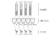
このような吐出信号によって、1つの画素領域に対してドット列を形成したときのドット配置の詳細を、図12に示す。
図12では、各吐出命令が吐出信号の時間帯に対して先頭から配置されているために、吐出命令数が少なければ、画素中心ライン(図中、1点鎖線)に対してドット列の重心位置がずれることとなる(図12中、ずれ量L1、L2)。
【0084】
これに対し、図13では、図12の例に対して、時間帯の中央近傍の基準位置(本実施形態では、時間帯の中央位置であって、画素中心ラインに一致する位置)をとり、その基準位置の前後に吐出命令を割り振るように制御した例を示すものである。
このようにすれば、画素中心ラインにドット列の重心位置を近づけることができる。図13の例では、ずれ量は、それぞれL1’、L2’であり、図12のずれ量L1、L2より少なくなっている。
【0085】
図14は、以上のようにして、吐出代行を行ったときのラインヘッド10の不良率をグラフにして示す図である。
図14中、▲1▼は、代行吐出を行わない場合である。また、▲2▼は、図5に示したように、1つの同一画素領域に、隣接する2つの液体吐出部のノズルから吐出されたインク液滴が着弾できるようにした場合である。さらにまた、▲3▼は、図6に示したように、1つの同一画素領域に、近隣に位置する3つの液体吐出部のノズルから吐出されたインク液滴が着弾できるようにした場合である。
【0086】
図14において、横軸は、吐出を停止するノズル(液体吐出部)数、すなわち不良となったノズル数を示し、縦軸は、ラインヘッド10の不良率を示している。ここで、不良率とは、インク液滴を着弾することができない画素列が発生する確率を意味する。
【0087】
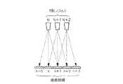
図15は、図14中、▲2▼の不良率の概念を説明する図である。1つの同一画素領域に、隣接する2つの液体吐出部のノズルから吐出されたインク液滴が着弾できるようにした場合には、図15中、左側の図に示すように、1つの不吐出のノズルN+1(図中、中央)が存在しても、その両隣のノズルN及びN+2が正常であれば、その両隣の液体吐出部のノズルN及びN+2を用いて、インク液滴の吐出代行を行うことができる。すなわち、図15中、点線で示すようなインク液滴の吐出はできないが、実線で示すインク液滴の吐出ができるために、結果として、全ての画素領域n〜n+3にインク液滴を着弾させることができる。
【0088】
これに対し、図14中、右側の図に示すように、隣接する(連続して配置される)2つの液体吐出部のノズルN+1及びN+2がともに不吐出になると、さらにその外側の正常な液体吐出部のノズルN及びN+3からのインク液滴の吐出代行によっては、インク液滴を着弾させることができない画素領域が発生する(図中、画素領域n+2)。このように、図14の▲2▼は、不吐出ノズルが増加したときに、不吐出ノズルが2つ連続で並ぶ確率を示すものである。
【0089】
同様に、図16は、図14中、▲3▼の不良率の概念を説明する図である。1つの同一画素領域に、近隣に位置する3つの液体吐出部のノズルから吐出されたインク液滴が着弾できるようにした場合には、図16中、左側の図に示すように、2つの連続するノズルN+1及びN+2が不吐出ノズルとなっても、さらにその外側の正常な液体吐出部のノズルN及びN+3を用いて、インク液滴の吐出代行を行うことができる。
【0090】
これに対し、図16中、右側の図に示すように、連続する3つの液体吐出部のノズルN+1、N+2及びN+3が全て不吐出となると、さらにその外側の正常な液体吐出部のノズルN及びN+4からのインク液滴の吐出代行によっては、インク液滴を着弾させることができない画素領域が発生する(図中、画素領域n+3)。図14の▲3▼は、不吐出ノズルが増加したときに、不吐出ノズルが3つ連続で並ぶ確率を示すものである。
【0091】
したがって、図14に示すように、吐出代行を行わない▲1▼の場合は、1つの液体吐出部のノズルが不吐出になるだけで、その液体吐出部が受け持つ画素領域にはインク液滴を着弾させることができなくなる。よって、1つの液体吐出部のノズルが不吐出になっただけで、ラインヘッド10の不良率は1になる。
【0092】
これに対し、図15に示す代行吐出を行えば、図14中、▲2▼に示すように、ラインヘッド10の不良率は大幅に(2〜3桁)改善される。すなわち、それは、歩詰まりが100〜1000倍程度改善されることを意味する。
なお、図14中、▲2▼の場合では、不吐出ノズルが約70個程度発生したときに、不良率が1になる。
【0093】
以上、本発明の一実施形態について説明したが、本発明は、上記実施形態に限定されることなく、例えば以下のような種々の変形が可能である。
(1)本実施形態では、印画紙の全幅に相当する分だけヘッド11を並設したラインヘッド10(ライン方式)を例に挙げたが、本発明をシリアル方式に適用することも可能である。
シリアル方式に適用する場合には、1つのヘッド11を用い、そのヘッド11を印画紙の幅方向に移動させるとともに、この移動中に画素領域にインク液滴を着弾させる。ここで、ヘッド11の移動中は、通常、印画紙を停止させておく。その印画が終了したら、印画紙を上記移動方向に垂直な方向に搬送した後、再度、ヘッド11を上記のように移動させる。
【0094】
本発明をシリアル方式に適用する場合において、ヘッド11は、ヘッド11の長手方向が印画紙の送り方向となるように配置される。すなわち、ラインヘッド10を構成する場合のヘッド11の配置に対して、90度だけ回転させた配置とする。
これにより、本発明を適用したシリアル方式の場合には、ヘッド11が90度だけ回転させた状態に配置されているので、インク液滴の吐出時の偏向方向は、印画紙の送り方向となる。
【0095】
従来のシリアル方式では、印画紙の幅方向、すなわちヘッド11の移動方向における画素列が形成されないと、印画紙の幅方向へのスジとなって目立ちやすくなるが(これに対し、印画紙の搬送方向のばらつきは目立ちにくい)、本発明のように代行吐出を行うことによって、そのようなスジの発生を減らすことができる。
【0096】
(2)本実施形態では、2つの発熱抵抗体13を並設し、それぞれに流れる電流値を変えて、各発熱抵抗体13上においてインクが沸騰するに至る時間(気泡発生時間)に時間差を設けるようにした。しかし、これに限らず、2つの発熱抵抗体13の抵抗値を同一とし、電流を流す時間のタイミングに差異を設けるものであっても良い。例えば2つの発熱抵抗体13ごとに、それぞれ独立したスイッチを設け、各スイッチを時間差をもってオンにすれば、各発熱抵抗体13上のインクに気泡が発生するに至る時間に時間差を設けることができる。さらには、発熱抵抗体13に流れる電流値を変えることと、電流を流す時間に時間差を設けたものとを組み合わせて用いても良い。
【0097】
(3)本実施形態では、1つのインク液室12内で発熱抵抗体13を2つ並設した例を示したが、これに限らず、1つのインク液室12内において3つ以上の発熱抵抗体13を並設したものを用いることも可能である。
【0098】
(4)本実施形態では、サーマル方式の液体吐出部として発熱抵抗体13を設けたものを例に挙げたが、これに限らず、静電吐出方式やピエゾ方式のものについても適用可能である。
静電吐出方式のエネルギー発生素子(発熱抵抗体13に相当するもの)は、振動板と、この振動板の下側に、空気層を介した2つの電極を設けたものである。そして、両電極間に電圧を印加し、振動板を下側にたわませ、その後、電圧を0Vにして静電気力を開放する。このとき、振動板が元の状態に戻るときの弾性力を利用してインク液滴を吐出するものである。
【0099】
この場合には、各エネルギー発生素子のエネルギーの発生に差異を設けるため、例えば振動板を元に戻す(電圧を0Vにして静電気力を開放する)ときに2つのエネルギー発生素子間に時間差を設けるか、又は印加する電圧値を2つのエネルギー発生素子で異なる値にすれば良い。
【0100】
また、ピエゾ方式のエネルギー発生素子は、両面に電極を有するピエゾ素子(圧電素子)と振動板との積層体を設けたものである。そして、ピエゾ素子の両面の電極に電圧を印加すると、圧電効果により振動板に曲げモーメントが発生し、振動板がたわみ、変形する。この変形を利用してインク液滴を吐出するものである。
この場合にも、上記と同様に、各エネルギー発生素子のエネルギーの発生に差異を設けるため、ピエゾ素子の両面の電極に電圧を印加するときに2つのピエゾ素子間に時間差を設けるか、又は印加する電圧値を2つのピエゾ素子で異なる値にすれば良い。
【0101】
(5)上記実施形態では、液体吐出装置としてプリンタを例に挙げたが、プリンタに限ることなく、種々の液体吐出装置に適用することができる。例えば、生体試料を検出するためのDNA含有溶液を吐出するための装置に適用することも可能である。
【0102】
【発明の効果】
本発明によれば、液滴を吐出できない液体吐出部が一部に存在したとしても、その欠陥を補うことができる。
これにより、液滴を吐出できない液体吐出部の影響を根本的に排除することができる。また、液滴を吐出できない液体吐出部が存在することで、本来であれば故障とされるような場合でも、それを救済することができるので、ヘッドのメンテナンス期間の延長や、ヘッドの寿命を延ばすことが可能となる。
【図面の簡単な説明】
【図1】本発明による液体吐出装置を適用したインクジェットプリンタのヘッドを示す分解斜視図である。
【図2】ラインヘッドの実施形態を示す平面図である。
【図3】図1のヘッドの液体吐出部をより詳細に示す平面図及び側面の断面図である。
【図4】分割した発熱抵抗体間の電流量の差(偏向電流)と偏向量との関係を示す実測値データである。
【図5】並設された液体吐出部のノズルと、インク液滴の着弾位置との関係を説明する正面図である。
【図6】並設された液体吐出部のノズルと、インク液滴の着弾位置との関係を説明する正面図であって、図5と異なる例を示すものである。
【図7】複数の液体吐出部から、それぞれ分配された吐出信号に従って所定方向に液滴を吐出することによりドット列を形成する制御方法を説明する図であり、図5に示す偏向吐出機能を有する液体吐出部の例である。
【図8】複数の液体吐出部から、それぞれ分配された吐出信号に従って所定方向に液滴を吐出することによりドット列を形成する制御方法を説明する図であり、図6に示す偏向吐出機能を有する液体吐出部の例である。
【図9】図7の例において、液体吐出部の選択、偏向方向、及び偏向振幅の制御を説明する図である。
【図10】図9において、代行吐出制御を可能とした場合のシステム概念を示す図である。
【図11】インク液滴の代行吐出を行うときのハードウェア上の制御の概略を説明する図である。
【図12】吐出信号によって、1つの画素領域に対してドット列を形成したときのドット配置の詳細を示す図である。
【図13】図12の例に対して、時間帯の中央位置であって画素中心ラインに一致する位置の前後に吐出命令を割り振るように制御した例を示す図である。
【図14】吐出代行を行ったときのラインヘッドの不良率をグラフにして示す図である。
【図15】図14中、▲2▼に相当する不良率の概念を説明する図である。
【図16】図14中、▲3▼に相当する不良率の概念を説明する図である。
【符号の説明】
10 ラインヘッド
11 ヘッド
12 インク液室
13 発熱抵抗体
18 ノズル[0001]
TECHNICAL FIELD OF THE INVENTION
The present invention relates to a liquid ejection apparatus and a liquid ejection method including a liquid ejection unit capable of deflecting a droplet ejection direction in a plurality of directions. More specifically, when there is a liquid discharge unit having a defective discharge of a liquid droplet, the discharge of the liquid droplet from the liquid discharge unit is stopped, and another liquid discharge unit can perform the discharge of the liquid droplet. It concerns technology.
[0002]
[Prior art]
2. Description of the Related Art An ink jet printer, which is one of the conventional liquid discharge devices, generally includes a head in which liquid discharge units having nozzles are linearly arranged. Then, a predetermined number of dots are arranged in the pixel area by sequentially ejecting minute ink droplets from each liquid ejection section of the head toward a recording medium such as photographic paper arranged opposite to the nozzle surface. Thus, a pixel is formed.
[0003]
Here, the liquid discharge unit may not be able to discharge the liquid droplets normally, for various reasons.
As one of them, there is a discharge failure due to dust adhering near the droplet outlet of the nozzle of the liquid discharge unit. As a solution to this case, a method of performing head cleaning is known.
[0004]
Second, there is a discharge failure due to clogging of the liquid discharge unit or disconnection of an energy generating element (for example, a heating element in the case of a thermal method) provided in the liquid discharge unit. In this case, there is no sufficient solution, and it is usual to deal with it by replacing the head.
[0005]
By the way, in the ink jet printer, the head reciprocates in a direction perpendicular to the feeding direction of the printing paper, performs printing during this reciprocating movement, and the printing paper is conveyed in a direction substantially perpendicular to the reciprocating direction. In addition to the serial method, a line method is known in which a head is formed so as to cover the entire width of the printing paper, and printing is performed while the printing paper is transported in the feed direction.
[0006]
In particular, as a line-type inkjet printer, a plurality of small head chips are arranged side by side so that the ends are connected to each other, and an appropriate signal processing is performed on each head chip, so that printing is performed at the stage of printing. It is known to perform recording connected to the entire width (for example, see Patent Document 1).
[0007]
Also, in a serial type ink jet printer, a method of overprinting is known for the purpose of expressing an intermediate gradation or the like.
This is a method in which ink droplets (dots) are repeatedly superimposed on one pixel region, and the characteristics of the liquid ejection unit are averaged. Then, the gaps are filled by arranging the dots so as to fill the gaps of the previously arranged dot rows.
[0008]
By adopting such overprinting, even if there is a liquid ejecting part having a somewhat poor characteristic or a liquid ejecting part that cannot eject a droplet at all, even if there is a part of the liquid ejecting part, the entire printing result shows that a part of the liquid ejecting part It is possible to make the defect of the ejection part inconspicuous.
[0009]
[Patent Document 1]
JP-A-2002-36522
[0010]
[Problems to be solved by the invention]
However, in the line type ink jet printer, the head does not reciprocate in a direction perpendicular to the photographic paper feeding direction, that is, it is not possible to perform the overprinting by re-recording the once recorded area.
Therefore, in the line method, there is a problem that, when a variation unique to the liquid ejection unit exists in the arrangement direction of the liquid ejection unit, the variation may be conspicuous as a streak.
[0011]
Furthermore, if there is at least one liquid ejection unit that cannot eject liquid droplets, white stripes occur in the pixel row where the liquid ejection unit is to be formed as a main body without any pixels being formed. In particular, there is a problem that when a picture, a graphic, or the like is required to have high image quality, the defect appears remarkably.
In a line-type inkjet printer, it is possible to increase the gradient by hitting the dots in the photographic paper feed direction so as to overlap, but the overprinting has the effect of only increasing the gradient. And does not contribute to the averaging in the overprinting as described above.
[0012]
Therefore, the problem to be solved by the present invention is a technique which has been already proposed by the present inventors and which can deflect and eject ink droplets (for example, Japanese Patent Application No. 2002-161928, Japanese Patent Application No. 2002-320861, and Japanese Patent Application No. 2002-208621). The method is to make it possible to compensate for the defect even if there is a liquid discharge portion that cannot discharge liquid droplets in a part of the liquid discharge portion.
[0013]
[Means for Solving the Problems]
The present invention solves the above-mentioned problems by the following means.
The invention according to
[0014]
(Action)
In the above-mentioned invention, the ejection direction of the droplet ejected from the liquid ejection unit is formed so as to be deflected in a plurality of directions. In addition, at least two liquid ejection units located in the vicinity, for example, two liquid ejection units that are continuous (adjacent) in a specific direction are formed so that droplets can land on at least one same pixel region.
[0015]
Furthermore, when there is a liquid discharge unit that stops discharging due to a droplet discharge failure, that information is stored in the discharge stop information storage unit.
Then, based on the stored information, at least a part of the ejection signal of the liquid droplet that the liquid ejection unit that stops ejection originally handles is transferred to at least one other liquid ejection unit located in the vicinity thereof, The liquid ejecting unit ejects the droplet on behalf of the droplet, and the droplet lands at a landing position when the liquid ejecting unit that stops ejection ejects the droplet.
[0016]
Therefore, even if there is a liquid discharge unit that stops discharging the liquid droplets (even if a defective liquid discharge unit occurs), another liquid discharge unit discharges the liquid droplets on behalf of the liquid discharge unit, thereby causing the defect. Can be supplemented.
[0017]
BEST MODE FOR CARRYING OUT THE INVENTION
Hereinafter, an embodiment of the present invention will be described with reference to the drawings and the like. In this specification, the term “droplet” refers to a very small amount (for example, about several picoliters) of liquid (ink in this embodiment) discharged from a
[0018]
Then, a predetermined number (zero, one or a plurality) of liquid droplets lands in one pixel area, and a pixel without a dot (one gradation), a pixel composed of one dot (two gradations), or Pixels (three or more gradations) composed of a plurality of dots are formed. An image is formed by arranging a large number of these pixels on a recording medium.
Note that the dot corresponding to the pixel does not completely enter the pixel area, and may protrude from the pixel area.
[0019]
Hereinafter, an embodiment of the liquid ejection device according to the present invention will be described.
The liquid ejection device of the present embodiment includes a line head for ejecting droplets.
Further, in this line head, a plurality of liquid ejection units are arranged in the width direction of the recording medium (the direction perpendicular to the conveying direction of the recording medium).
Furthermore, the liquid ejection unit is
(1) a liquid chamber for accommodating droplets to be ejected (corresponding to the
(2) an energy generating element for applying energy to the liquid in the liquid chamber (corresponding to the
(3) a nozzle sheet (ejection port forming member) in which a nozzle (ejection port) for ejecting the liquid in the liquid chamber is formed by an energy generating element.
It is provided with.
[0020]
By controlling the manner in which energy is applied to the liquid by the energy generating element, the discharge direction of the droplet discharged from the nozzle is deflected in a plurality of directions in the direction in which the liquid discharge units are arranged. For example, the energy generating element is disposed in at least a part of a region of one surface of the liquid chamber, and controls an energy distribution on the energy generating element. The energy distribution is controlled by providing a difference in the way of applying energy, or by providing a difference in the energy distribution between one region and another one region on the energy generating element. The liquid ejection device used in the present invention is not limited to the present embodiment.
[0021]
FIG. 1 is an exploded perspective view showing a
In the
[0022]
The
Furthermore, the
[0023]
The
[0024]
The one
[0025]
That is, the
[0026]
Further, in this embodiment, a plurality of
[0027]
Here, the pitch between nozzles at each end of the
[0028]
Furthermore, a color line head can be configured by arranging a plurality of line heads 10 in parallel with a predetermined gap therebetween and supplying different color inks to each
[0029]
Subsequently, the liquid ejection unit of the present embodiment will be described in more detail.
FIG. 3 is a plan view and a cross-sectional side view showing the liquid ejection unit of the
As shown in FIG. 3, in the
[0030]
As described above, when the
On the other hand, if a time difference is given to the bubble generation time of the two divided
[0031]
FIG. 4 shows the difference in the amount of current between the two divided
[0032]
As described above, the time difference between the bubble generation times on the two
[0033]
In the present embodiment, the distribution of energy generation in the lower surface area in the
[0034]
Using the configuration described above, in the present invention, at least two liquid ejection units located in the vicinity are formed so that droplets can land on at least one same pixel region. In particular, assuming that the arrangement pitch in the arrangement direction of the liquid ejection units is P, each liquid ejection unit is located in the arrangement direction of the
(Equation 1) ± (1/2 × P) × N (where N is a positive integer)
Is formed so that a droplet can be landed at the position.
[0035]
FIG. 5 is a front view illustrating the relationship between the
In FIG. 5, ink droplets ejected from the
[0036]
In FIG. 5, for example, the nozzle N can land ink droplets on the pixel region n and the pixel region n + 1, respectively. Here, when the central axis of the nozzle N is extended to the recording medium (the landing position of the ink droplet), the intersection between the central axis of the nozzle N and the recording medium is defined by the middle point between the pixel area n and the pixel
The nozzle N + 1 can land ink droplets on the pixel area n + 1 and the pixel area n + 2, respectively.
[0037]
In this way, a dot can be formed by deflecting the ink droplet from the nozzle N to the right in FIG. 5 and ejecting it to the pixel region n + 1, or the ink droplet can be ejected from the nozzle N + 1 in FIG. It is also possible to form a dot by deflecting it toward the middle or left and ejecting it.
The same applies to the relationship between the
[0038]
In FIG. 5, the
± (1/2 × P) × 1
Is formed so that a droplet can be landed at the position. That is, this corresponds to the case where N = 1 in the above equation (1).
For example, in the case of 600 [DPI], since the nozzle pitch is 42.33 [μm], the deflection amount at the impact position is 21.15 [μm] on one side.
[0039]
FIG. 6 shows an example different from FIG. In FIG. 6, ink droplets ejected from the
In FIG. 6, the
[0040]
At this time, the ink droplets can be ejected from the nozzle N + 1 perpendicularly to the recording medium, and land on the pixel region n + 1.
In addition, it is also possible to deflect the ink droplet to the right in FIG. 6 and discharge it from the nozzle N to land the ink droplet on the pixel region n + 1.
Further, it is also possible to deflect the ink droplet to the left in FIG. 6 and eject it from the nozzle N + 2 to land the ink droplet on the pixel
The same applies to the relationship between the
[0041]
Therefore, in FIG. 6, the
± (1/2 × P) × 2
Is formed so that a droplet can be landed at the position. That is, this corresponds to the case where N = 2 in the above equation (1).
[0042]
Further, according to the present invention, a discharge signal of a droplet for forming a dot row in a photographic paper feeding direction (a relative movement direction between the
FIG. 7 is a diagram for explaining this control method, and is an example of the liquid ejection section having the deflection ejection function shown in FIG. That is, in the
[0043]
In FIG. 7, the
[0044]
In FIG. 7, in order to form a dot row corresponding to one pixel, an ejection signal corresponding to each dot row is input. The ejection signal is a signal sequence composed of an ejection command for each dot of the dot array (indicated by a circle in the ejection signal in FIG. 7).
[0045]
In FIG. 7, the squares (slots) of the ejection signals indicate their temporal arrangement. At the time (timing) when a circle (ejection command) exists, the ink liquid from the
[0046]
At this time, for example, each ejection command of the ejection signal S is alternately distributed to the nozzles (liquid ejection units) N and N + 1. That is, the first ejection command of the ejection signal S (the ejection command located at the bottom in FIG. 7) is input to the nozzle N + 1, and the ink droplet is deflected from the nozzle N + 1 to the left in the drawing, and The ink droplet lands on the dot row n. The next ejection command is input to the nozzle N, and the ink droplet is deflected and ejected rightward in the drawing from the nozzle N, and the ink droplet lands on the dot row n.
[0047]
In this way, for one ejection signal S, the ejection commands are alternately sequentially distributed to the nozzles N and N + 1, and ink droplets are ejected in a predetermined direction. Is formed.
Therefore, each ejection command of one ejection signal is sequentially distributed to a plurality of liquid ejection units, and ink droplets are ejected in a predetermined direction, and finally, a dot row corresponding to the ejection signal is formed. .
[0048]
FIG. 8 is a diagram for explaining a control method similar to that of FIG. 7, and is an example of the liquid ejection unit having the deflection ejection function shown in FIG. That is, in the
[0049]
In FIG. 8, focusing on the ejection signal S + 1, the nozzle N + 1, and the dot row n + 1, the first ejection command of the ejection signal S + 1 (the ejection command located at the bottom in FIG. 8) is input to the nozzle N + 2, and the nozzle N + 2 Then, the ink droplet is deflected and ejected leftward in the drawing, and the ink droplet lands on the dot row n + 1. The next ejection command is input to the nozzle N + 1, and the ink droplet is ejected from the nozzle N + 1 without being deflected (immediately below), and the ink droplet lands on the dot row n + 1. Further, the next ejection command is input to the nozzle N, and the ink droplet is deflected and ejected rightward in the drawing from the nozzle N, and the ink droplet lands on the dot row n + 1.
[0050]
The above-described distribution of the ejection commands shows only one mode, and various modes can be considered as a method of distributing each ejection command of the ejection signal. For example, the first and second ejection commands of the ejection signal are distributed to one (identical) liquid ejection unit, and the third and fourth ejection commands are distributed to another (identical) liquid ejection unit.・ The method may be used.
[0051]
FIG. 9 is a diagram illustrating the selection of the liquid ejection unit, the control of the deflection direction, and the control of the deflection amplitude in the example of FIG. 7.
The
The switch A is for selecting a liquid ejection unit, and is a switch for determining to which liquid ejection unit the ejection command of the ejection signal is input. For example, by switching the switch A, all the liquid ejection units can be simultaneously switched in the same direction. For example, when switching is performed as shown in FIG. 9, the ejection signal S + 1 is input to the nozzle N.
[0052]
A switch B for switching the deflection direction of the ink droplet is a switch for switching whether the ink droplet is deflected leftward or rightward in the drawing. The deflection direction of the discharge unit is simultaneously switched to the same direction.
[0053]
Then, the switches A and B are operated in agreement. For example, when the switch A is switched as shown in FIG. 9, the ejection command of the ejection signal S + 1 is input to the nozzle N. At this time, the switch B deflects the liquid droplet to the right in the figure. The liquid discharge unit is controlled so as to discharge the liquid. As a result, the ink droplets are deflected and ejected from the nozzle N to the right side in the figure, forming one dot of the dot row n + 1.
[0054]
Further, the control terminal C is a terminal for controlling the deflection amplitude in an analog manner within the range of the characteristics shown in FIG. When an appropriate voltage is applied to the control terminal C, a current of a predetermined value flows through the
[0055]
Next, a description will be given of the alternate discharge control (droplet substitute means) of the droplet by another liquid ejecting unit when the ejection failure of the droplet occurs in the liquid ejecting unit.
FIG. 10 is a diagram showing a system concept in a case where proxy discharge control is enabled in FIG.
In FIG. 10, a switch A1 is similar to the switch A in FIG. Further, in FIG. 10, a switch A2 that is individually set for each liquid ejection unit is provided. When the switch A2 is turned on, the ejection command of the ejection signal is input to the liquid ejection unit as in FIG. 9, but when turned off, the ejection command of the ejection signal is sent to the liquid ejection unit. Never.
Other switches B and control terminals C are the same as those in FIG.
[0056]
In order to determine whether or not the liquid ejecting unit stops ejecting due to an ink droplet ejection failure (including an ink droplet that cannot be ejected at all and an ink droplet that can hardly be ejected), for example, Method.
For example, first, there is a method in which an appropriate test pattern is printed, the pattern is compared with a normal pattern, and if the normal pattern is not correctly printed, it is determined that a discharge failure has occurred. In addition, this method will determine visually.
[0057]
Secondly, as a mechanical method, an ink droplet to be ejected is charged, the ink droplet is dropped on a specific insulated electrode, and the ink droplet from the liquid ejection portion is changed by a change in the amount of electricity. To determine whether or not the ejection is normal. As described above, various methods can be used as a method for specifying the liquid discharge unit where the discharge failure of the ink droplet exists.
[0058]
Then, the switch A2 is turned on for a liquid discharge unit that is not defective (normal), but the switch A2 is turned off for the liquid discharge unit that has been determined to have defective discharge, in order to stop discharging liquid droplets. . The example of FIG. 10 illustrates a state in which the switch A2 corresponding to the nozzle N + 1 is turned off (the switches A2 corresponding to nozzles other than the nozzle N + 1 are on).
[0059]
As a specific circuit, the first input terminal becomes “1” when the ejection command is input (1.5 μsec), and becomes “0” otherwise, and “1” when the switch A2 is on. , And an AND gate having a second input terminal that is "0" when the output is off is used so that the output is input to the liquid ejection unit. Thus, when the switch A2 is off (when there is a discharge failure), a discharge command is not input to the liquid discharge unit.
[0060]
In addition, among the liquid ejection units in the
[0061]
Next, control of the ejection signal will be described.
When there is information for stopping the ejection, that is, when the information of the liquid ejection unit for which the ejection is stopped is stored in the above-described ejection stop information storage means, the ejection signal which the liquid ejection unit originally handles is stopped. At least one other liquid ejecting unit located in the vicinity of the liquid ejecting unit to be moved, in particular, in this embodiment, the liquid ejecting unit is moved to both adjacent liquid ejecting units. Control. In this case, control is performed so as to shift to an idle time period during which no ink droplets are ejected in the liquid ejection section.
[0062]
In the example of FIG. 10, the nozzle of the liquid discharge unit that stops discharging is the nozzle N + 1. The ejection signals originally assigned to the liquid ejection unit are ejection signals S + 1 and S + 2. For this reason, the ejection signal S + 1 is controlled so that the ink droplets are ejected from the nozzle N to form a dot row n + 1 corresponding to the ejection signal S + 1. The ejection signal S + 2 is controlled so that a droplet is ejected from the nozzle N + 2 to form a dot row n + 2 corresponding to the ejection signal S + 2.
[0063]
Here, in the present embodiment, in the generation of the ink droplet ejection signal, a normal mode ejection signal that does not involve the liquid ejection unit that stops the ejection of the ink droplet, and the liquid ejection unit that stops the ejection of the ink droplet And a correction mode discharge signal for transferring the discharge signal to another liquid discharge unit located on both sides of the liquid discharge unit that stops discharging, which is a discharge signal that involves discharge.
[0064]
In FIG. 10, the ejection signals S, S + 3, and S + 4 do not involve the liquid ejection unit (nozzle N + 1) that stops the ejection of the ink droplets (that is, are input to the liquid ejection unit that stops the ejection of the ink droplets). In this case, a discharge signal in a normal mode is generated and input to a predetermined liquid discharge unit.
[0065]
On the other hand, the ejection signals S + 1 and S + 2 involve the liquid ejection unit (nozzle N + 1) that stops the ejection of the ink droplets (that is, are input to the liquid ejection unit that stops the ejection of the ink droplets). Since these are ejection signals, in this case, ejection signals in the correction mode are generated as these ejection signals.
[0066]
In the ejection signal in the correction mode, the time zone of one ejection command is twice as long as the time zone of the ejection command in the ejection signal in the normal mode.
In FIG. 10, each square of the ejection signals S + 1 and S + 2, which are ejection signals in the correction mode, is twice as long as the masses of the other ejection signals.
Therefore, for example, taking the ejection signal S + 1 as an example, the first ejection command (the ejection command indicated by the circle at the bottom in the figure) exists in the time slot for two squares in the normal mode.
[0067]
Then, the switch A1 for selecting the liquid ejection unit is alternately switched to the nozzles N and N + 1, so that the ejection signal S + 1 is alternately input to the nozzles N and N + 1. Here, the switch A2 of the nozzle N is on (connected), while the switch A2 of the nozzle N + 1 is off (disconnected). Therefore, even if the ejection command of the ejection signal S + 1 is input to the nozzle N + 1, no ink droplet is ejected in accordance with the ejection command (the liquid ejection unit related to the nozzle N + 1 is not driven).
[0068]
On the other hand, when the ejection command of the ejection signal S + 1 is input to the nozzle N, the ink droplet is ejected according to the ejection command.
As described above, in the ejection signal S + 1, the time period of one ejection command is set to twice that of the normal mode. Therefore, each ejection command of the ejection signal S + 1 is applied to both the nozzles N and N + 1. Is input to Thus, no ink droplet corresponding to the ejection command of the ejection signal S + 1 is ejected from the nozzle N + 1, but an ink droplet corresponding to the ejection command of the ejection signal S + 1 is ejected from the nozzle N. As a result, ink droplets corresponding to all the ejection commands of the ejection signal S + 1 are ejected from the nozzle N.
[0069]
Therefore, a part of the ejection command of the ejection signal S is inputted to the nozzle N (the other part is inputted to the nozzle N-1 (shown by a dotted line)), and all the ejection signals of the ejection signal S + 1 are given. An instruction is entered.
[0070]
When the ejection command of the ejection signal S is input to the nozzle N, the droplet is shifted by the control of the switch B such that the landing position is shifted to the left side by half the nozzle pitch from the center axis of the nozzle N in the drawing. Is deflected and discharged. Accordingly, the dots forming the dot row n are formed by the ink droplets ejected from the nozzles N based on the ejection command of the ejection signal S.
[0071]
On the other hand, when the ejection command of the ejection signal S + 1 is input to the nozzle N, the control of the switch B causes the ink liquid to shift from the center axis of the nozzle N by の of the nozzle pitch to the right in the drawing. Drops are deflected and ejected. Thus, based on the ejection command of the ejection signal S + 1, all the dots of the dot row n + 1 are formed by the ink droplets ejected from the nozzles N.
As described above, the ejection command of the ejection signal S + 1 is input to the nozzle N and also to the nozzle N + 1. However, since the switch A2 is off, an ink droplet is ejected from the nozzle N + 1. No dot in the dot row n + 1 is formed.
[0072]
By performing control as described above, when there is a liquid ejection unit (nozzle 18) that does not eject ink droplets, a liquid ejection unit that does not eject ink droplets is placed in another liquid ejection unit adjacent to the liquid ejection unit. Transfer the ejection signal originally assigned to the other liquid ejection unit so that the ink droplet is ejected instead of another liquid ejection unit. Therefore, an ink droplet ejection failure occurs in the
[0073]
In FIG. 10, 16 squares are taken in the normal mode as a total time zone of one ejection signal. Thus, in the correction mode, each cell is twice as long as the normal mode, so that the total time period of the ejection signal in the correction mode is eight cells.
Here, when applied to a printer as in the present embodiment, the absorption amount of ink droplets per pixel of photographic paper is 5 to 6 drops in consideration of maintenance of image quality and drying time (1). (When the average volume of the droplets is about 4.5 picoliters). In addition, when an efficient binary number is used in the signal processing of the ejection signal, the number of bits becomes 3 bits (8 cells). Therefore, in the present embodiment, the above configuration is adopted in consideration of the maximum number of ejection commands per pixel and signal processing.
[0074]
Further, for example, when the maximum number of ejection commands per pixel is set to 6 for 8 cells, the maximum number of ejection commands at the time of alternate ejection is also 6. Therefore, in order to process ejection signals in the correction mode together, , 1.5 times as long as the ejection signal in the normal mode.
Furthermore, when the number of ejection commands is close to the maximum (for example, 5 to 6), the density is close to the maximum, and the γ (gamma) characteristic is fairly gentle. For this reason, in the correction mode, for example, if up to four ejection commands are targeted for substitute ejection, it is possible to cope with a normal signal processing system without adding a new time zone, and the printing speed is reduced. Can be eliminated.
[0075]
Therefore, in generating the ejection signal in the correction mode, all ejection commands may be substituted, but if priority is given to maintaining the printing speed, substitute ejection is performed for only a part of the ejection commands. May be. Which of these is adopted is arbitrary.
In addition, both an "image quality priority mode" in which all ejection commands are substituted even when the printing speed is reduced, and a "speed priority mode" in which proxy ejection is performed for only some ejection commands while maintaining the printing speed are prepared in advance. In addition, it is possible to select one of them, or to switch between them according to the content of the image and the like.
[0076]
Further, when the liquid discharge unit performs proxy discharge, it is conceivable that the printing speed is reduced from that in the normal state or the operation speed of the liquid discharge unit is increased accordingly.
Here, considering the refill time required to refill the
[0077]
When the relative speed between the
Q = (formation cycle of new pixel / formation cycle of original pixel)
Is set, and the relative speed is controlled so as to be 1 / Q.
In this way, the substitute ejection can be performed while keeping the size and the aspect ratio of the printed image constant.
[0078]
FIG. 11 is a diagram for explaining an outline of control on hardware when performing proxy ejection of ink droplets as described above. FIG. 11 also shows an outline of control in the conventional method.
In FIG. 11, in the conventional method, an ejection signal is merely sent to a head based on a recording signal generation map. On the other hand, in the present embodiment, an ejection signal is sent to the
[0079]
As shown in FIG. 10 and the like, the recording
[0080]
The deflection
Further, in FIG. 10, the liquid discharge
[0081]
The ejection signal generated by the recording
[0082]
Next, a method of allocating the ejection command to the time zone of the ejection signal will be described.
In the above-described FIG. 10 and the like, the ejection command is arranged from the top in the time zone of one ejection signal, that is, the ejection command is arranged from the bottom cell in the time zone (mass) of the ejection signal. are doing.
[0083]
FIG. 12 shows details of dot arrangement when a dot row is formed for one pixel region by such an ejection signal.
In FIG. 12, since each ejection command is arranged from the beginning with respect to the time zone of the ejection signal, if the number of ejection commands is small, the center of gravity of the dot row with respect to the pixel center line (the dashed line in the figure). The position shifts (shift amounts L1 and L2 in FIG. 12).
[0084]
On the other hand, in FIG. 13, a reference position near the center of the time zone (in this embodiment, the center position of the time zone and a position coinciding with the pixel center line) is taken with respect to the example of FIG. An example is shown in which control is performed so that an ejection command is allocated before and after the reference position.
By doing so, the position of the center of gravity of the dot row can be brought closer to the pixel center line. In the example of FIG. 13, the shift amounts are L1 ′ and L2 ′, respectively, which are smaller than the shift amounts L1 and L2 in FIG.
[0085]
FIG. 14 is a diagram showing a graph of the defect rate of the
In FIG. 14, {circle around (1)} indicates a case where the substitute ejection is not performed. (2) is a case where ink droplets ejected from the nozzles of two adjacent liquid ejection units can land on one and the same pixel area as shown in FIG. Further, (3) shows a case where, as shown in FIG. 6, ink droplets discharged from nozzles of three liquid discharge units located in the vicinity can land on one and the same pixel region. .
[0086]
In FIG. 14, the horizontal axis indicates the number of nozzles (liquid discharge units) that stop discharging, that is, the number of defective nozzles, and the vertical axis indicates the failure rate of the
[0087]
FIG. 15 is a diagram for explaining the concept of the failure rate of (2) in FIG. In the case where ink droplets ejected from the nozzles of two adjacent liquid ejecting sections can land on one and the same pixel area, one non-ejection area as shown in FIG. Even if the nozzle N + 1 (the center in the figure) exists, if the nozzles N and N + 2 on both sides thereof are normal, the nozzle N and N + 2 of the liquid discharge part on both sides perform the ink droplet ejection proxy. be able to. That is, in FIG. 15, the ink droplets indicated by the dotted lines cannot be discharged, but the ink droplets indicated by the solid lines can be discharged. As a result, the ink droplets land on all the pixel regions n to n + 3. be able to.
[0088]
On the other hand, when the nozzles N + 1 and N + 2 of the two adjacent (continuously arranged) liquid ejection units are not ejected as shown in the right-side diagram in FIG. Depending on the substitution of the ejection of the ink droplets from the nozzles N and N + 3 of the ejection unit, a pixel region in which the ink droplet cannot be landed is generated (pixel region n + 2 in the figure). As described above, (2) in FIG. 14 indicates the probability that two non-discharge nozzles are continuously arranged when the number of non-discharge nozzles increases.
[0089]
Similarly, FIG. 16 is a diagram for explaining the concept of the defect rate of (3) in FIG. In a case where ink droplets ejected from nozzles of three liquid ejection units located in the vicinity can land on one and the same pixel area, as shown in the left side of FIG. Even if the nozzles N + 1 and N + 2 are non-ejection nozzles, the ink droplets can be alternately ejected using the nozzles N and N + 3 of the normal liquid ejection unit on the outside.
[0090]
On the other hand, as shown in the right-hand diagram in FIG. 16, when all the nozzles N + 1, N + 2, and N + 3 of the three consecutive liquid discharge units fail to discharge, the nozzles N and N of the normal liquid discharge units further outside the nozzles N and N + 2 Depending on the substitution of the ink droplet from N + 4, a pixel region in which the ink droplet cannot be landed is generated (pixel region n + 3 in the figure). (3) in FIG. 14 shows the probability that three non-ejection nozzles are arranged in a row when the number of non-ejection nozzles increases.
[0091]
Therefore, as shown in FIG. 14, in the case of (1) in which the ejection proxy is not performed, only the nozzle of one liquid ejection unit becomes non-ejection, and the ink droplets are applied to the pixel area covered by the liquid ejection unit. You will not be able to land. Therefore, the failure rate of the
[0092]
On the other hand, if the substitute ejection shown in FIG. 15 is performed, the failure rate of the
In FIG. 14, in the case of (2), the failure rate becomes 1 when about 70 non-ejection nozzles are generated.
[0093]
As mentioned above, although one Embodiment of this invention was described, this invention is not limited to the said Embodiment, For example, the following various deformation | transformation is possible.
(1) In the present embodiment, the line head 10 (line system) in which the
When applied to the serial system, one
[0094]
When the present invention is applied to a serial system, the
Accordingly, in the case of the serial system to which the present invention is applied, since the
[0095]
In the conventional serial method, if a pixel row is not formed in the width direction of the photographic paper, that is, in the moving direction of the
[0096]
(2) In the present embodiment, two
[0097]
(3) In the present embodiment, an example in which two
[0098]
(4) In the present embodiment, an example in which the
The electrostatic discharge type energy generating element (corresponding to the heating resistor 13) is provided with a vibrating plate and two electrodes provided below the vibrating plate via an air layer. Then, a voltage is applied between the two electrodes to bend the diaphragm downward, and then the voltage is set to 0 V to release the electrostatic force. At this time, ink droplets are ejected by utilizing the elastic force when the diaphragm returns to the original state.
[0099]
In this case, in order to provide a difference in the energy generation of each energy generating element, a time difference is provided between the two energy generating elements, for example, when the diaphragm is returned to its original state (voltage is set to 0 V to release the electrostatic force). Alternatively, the applied voltage value may be different between the two energy generating elements.
[0100]
Further, the piezo-type energy generating element is provided with a laminate of a piezo element (piezoelectric element) having electrodes on both surfaces and a diaphragm. When a voltage is applied to the electrodes on both sides of the piezo element, a bending moment is generated in the diaphragm due to the piezoelectric effect, and the diaphragm bends and deforms. The ink droplet is ejected by utilizing this deformation.
Also in this case, similarly to the above, in order to provide a difference in the energy generation of each energy generating element, when applying a voltage to the electrodes on both surfaces of the piezoelectric element, a time difference is provided between the two piezoelectric elements, or What is necessary is just to make the voltage values to be different between the two piezo elements.
[0101]
(5) In the above embodiment, a printer was described as an example of a liquid ejection device, but the invention is not limited to a printer, and can be applied to various liquid ejection devices. For example, the present invention can be applied to an apparatus for discharging a DNA-containing solution for detecting a biological sample.
[0102]
【The invention's effect】
ADVANTAGE OF THE INVENTION According to this invention, even if the liquid discharge part which cannot discharge a droplet exists in a part, the defect can be compensated.
Accordingly, it is possible to fundamentally eliminate the influence of the liquid discharge unit that cannot discharge the droplet. In addition, since there is a liquid discharge portion that cannot discharge liquid droplets, even if a failure would otherwise occur, it can be remedied, so that the maintenance period of the head can be extended and the life of the head can be extended. It can be extended.
[Brief description of the drawings]
FIG. 1 is an exploded perspective view showing a head of an ink jet printer to which a liquid ejection device according to the present invention is applied.
FIG. 2 is a plan view showing an embodiment of a line head.
3A and 3B are a plan view and a side sectional view showing a liquid ejection unit of the head of FIG. 1 in more detail.
FIG. 4 is actually measured value data showing a relationship between a difference in current amount (deflection current) between divided heating resistors and a deflection amount.
FIG. 5 is a front view illustrating the relationship between nozzles of liquid ejection units arranged in parallel and landing positions of ink droplets.
FIG. 6 is a front view illustrating a relationship between nozzles of liquid ejection units arranged in parallel and landing positions of ink droplets, and shows an example different from FIG. 5;
FIG. 7 is a diagram illustrating a control method for forming a dot row by discharging droplets in a predetermined direction from a plurality of liquid discharge units in accordance with respective distributed discharge signals. It is an example of a liquid discharge unit having the above.
FIG. 8 is a diagram illustrating a control method for forming a dot row by discharging droplets in a predetermined direction from a plurality of liquid discharge units in accordance with respective distributed discharge signals. The deflection discharge function shown in FIG. It is an example of a liquid discharge unit having the above.
FIG. 9 is a diagram for explaining selection of a liquid ejection unit, control of a deflection direction, and control of a deflection amplitude in the example of FIG. 7;
FIG. 10 is a diagram illustrating a system concept in a case where proxy discharge control is enabled in FIG. 9;
FIG. 11 is a diagram illustrating an outline of control on hardware when performing proxy ejection of ink droplets.
FIG. 12 is a diagram illustrating details of dot arrangement when a dot row is formed in one pixel region by an ejection signal.
FIG. 13 is a diagram illustrating an example in which, in the example of FIG. 12, control is performed so that an ejection command is allocated before and after a position that is the center position of a time zone and coincides with a pixel center line.
FIG. 14 is a graph showing a defect rate of the line head when performing the ejection proxy.
FIG. 15 is a diagram for explaining the concept of the defect rate corresponding to (2) in FIG. 14;
FIG. 16 is a diagram for explaining the concept of the defect rate corresponding to (3) in FIG. 14;
[Explanation of symbols]
10 line head
11 head
12 Ink liquid chamber
13 Heating resistor
18 nozzles
Claims (11)
Translated fromJapanese前記液体吐出部は、液滴の吐出方向を前記特定方向において複数の方向に偏向可能であり、
近隣に位置する少なくとも2つの前記液体吐出部は、少なくとも1つの同一画素領域に液滴を着弾させることが可能であり、
複数の前記液体吐出部のうち、液滴の吐出不良により吐出を停止する前記液体吐出部に関する情報を記憶する吐出停止情報記憶手段と、
前記吐出停止情報記憶手段に記憶された情報に基づいて、液滴の吐出を停止する前記液体吐出部が本来受け持つ液滴の吐出信号の少なくとも一部を、液滴の吐出を停止する前記液体吐出部の近隣に位置する少なくとも1つの他の前記液体吐出部に移すとともに、液滴の吐出を停止する前記液体吐出部が前記吐出信号に従って液滴を吐出したときの液滴の着弾位置に、その少なくとも1つの他の前記液体吐出部から吐出した液滴を着弾させるように制御する液滴吐出代行手段と
を備える
ことを特徴とする液体吐出装置。A head in which a plurality of liquid ejection units having nozzles are arranged in a specific direction, and a liquid droplet landing target for landing liquid droplets and the head are relatively moved in a direction substantially perpendicular to the specific direction; A liquid ejecting apparatus that ejects a predetermined number of droplets from the liquid ejecting unit, and forms a pixel including a predetermined number of dots in a pixel area,
The liquid ejecting unit is capable of deflecting a droplet ejection direction in a plurality of directions in the specific direction,
At least two of the liquid ejection units located in the vicinity can land droplets on at least one same pixel region,
Among a plurality of the liquid ejection units, an ejection stop information storage unit that stores information about the liquid ejection unit that stops ejection due to a droplet ejection failure,
Based on the information stored in the ejection stop information storage unit, the liquid ejection unit that stops the ejection of the droplet is configured to stop at least a part of the ejection signal of the droplet that is originally assigned to the liquid ejection unit that stops the ejection of the droplet. To the at least one other liquid ejection unit located in the vicinity of the unit, and to the landing position of the droplet when the liquid ejection unit that stops ejection of the droplet ejects the droplet according to the ejection signal. A liquid discharge device comprising: a liquid drop discharge substitute means for controlling a liquid drop discharged from at least one other liquid discharge unit to land.
前記液体吐出部は、液滴の吐出方向を前記特定方向において複数の方向に偏向可能であり、
近隣に位置する少なくとも2つの前記液体吐出部は、少なくとも1つの同一画素領域に液滴を着弾させることが可能であり、
画素領域に液滴を着弾させて所定数のドットからなる画素を形成する場合に、その画素領域に対して液滴を着弾させることが可能な複数の前記液体吐出部のうち、選択されたいずれかの前記液体吐出部によりその画素領域に液滴を着弾させるようにし、
複数の前記液体吐出部のうち、液滴の吐出不良により吐出を停止する前記液体吐出部に関する情報を記憶する吐出停止情報記憶手段と、
前記吐出停止情報記憶手段に記憶された情報に基づいて、液滴の吐出を停止する前記液体吐出部が本来受け持つ液滴の吐出信号の少なくとも一部を、液滴の吐出を停止する前記液体吐出部の近隣に位置する少なくとも1つの他の前記液体吐出部における液滴を吐出しない空き時間帯に移すとともに、その少なくとも1つの他の前記液体吐出部から前記空き時間帯に前記吐出信号に従って液滴を吐出し、液滴の吐出を停止する前記液体吐出部が前記吐出信号に従って液滴を吐出したときの液滴の着弾位置に、液滴を着弾させるように制御する液滴吐出代行手段と
を備える
ことを特徴とする液体吐出装置。A head in which a plurality of liquid ejection units having nozzles are arranged in a specific direction, and a liquid droplet landing target for landing liquid droplets and the head are relatively moved in a direction substantially perpendicular to the specific direction; A liquid ejecting apparatus that ejects a predetermined number of droplets from the liquid ejecting unit, and forms a pixel including a predetermined number of dots in a pixel area,
The liquid ejecting unit is capable of deflecting a droplet ejection direction in a plurality of directions in the specific direction,
At least two of the liquid ejection units located in the vicinity can land droplets on at least one same pixel region,
When a droplet composed of a predetermined number of dots is formed by landing a droplet on a pixel region, any one of the plurality of liquid ejection units capable of landing a droplet on the pixel region is selected. The liquid ejecting section causes a droplet to land on the pixel area,
Among a plurality of the liquid ejection units, an ejection stop information storage unit that stores information about the liquid ejection unit that stops ejection due to a droplet ejection failure,
Based on the information stored in the ejection stop information storage unit, the liquid ejection unit that stops the ejection of the droplet is configured to stop at least a part of the ejection signal of the droplet that is originally assigned to the liquid ejection unit that stops the ejection of the droplet. The liquid droplets are transferred to at least one other liquid discharge unit located in the vicinity of the liquid discharge unit in a vacant time zone in which the liquid droplets are not discharged, and the liquid droplets are supplied from the at least one other liquid discharge unit to the vacant time period according to the discharge signal. And a droplet discharge proxy means for controlling the liquid droplets to land at the landing positions of the liquid droplets when the liquid discharging unit that discharges the liquid droplets in accordance with the discharge signal discharges the liquid droplets. A liquid ejection device comprising:
前記液体吐出部の前記特定方向における並設ピッチをPとしたとき、
各前記液体吐出部は、自己の前記液体吐出部の中心位置に対して、前記特定方向において、
±(1/2×P)×N(ここで、Nは、正の整数)
の位置に液滴を着弾させることが可能である
ことを特徴とする液体吐出装置。The liquid ejection device according to claim 2,
When the pitch at which the liquid ejection units are arranged in the specific direction is P,
Each of the liquid ejecting sections is, with respect to a center position of the liquid ejecting section itself, in the specific direction,
± (1/2 × P) × N (where N is a positive integer)
Wherein the liquid droplets can be landed at the position of (1).
前記相対移動方向におけるドット列を形成するための液滴の吐出信号を、その吐出信号に対応する液滴の着弾位置に液滴を着弾可能な少なくとも2つの前記液体吐出部に順次分配し、その少なくとも2つの前記液体吐出部からそれぞれ分配された前記吐出信号に従って所定方向に液滴を吐出することにより、前記ドット列を形成する
ことを特徴とする液体吐出装置。The liquid ejection device according to claim 2,
A discharge signal of a droplet for forming a dot row in the relative movement direction is sequentially distributed to at least two of the liquid discharge units capable of landing a droplet at a landing position of the droplet corresponding to the discharge signal. A liquid discharge apparatus, wherein the dot row is formed by discharging droplets in a predetermined direction in accordance with the discharge signals respectively distributed from at least two of the liquid discharge units.
前記相対移動方向におけるドット列を形成するための液滴の吐出信号の処理において、前記液体吐出部を選択するための信号と、液滴の吐出方向を制御するための信号とを共有するか、又は一方を他方に同期させるように制御する
ことを特徴とする液体吐出装置。The liquid ejection device according to claim 2,
In the processing of the droplet ejection signal for forming a dot row in the relative movement direction, a signal for selecting the liquid ejection unit and a signal for controlling the droplet ejection direction are shared, Alternatively, a liquid ejection apparatus is controlled so that one is synchronized with the other.
前記相対移動方向におけるドット列を形成するための液滴の吐出信号の生成において、液滴の吐出を停止する前記液体吐出部が関与しない通常モードの吐出信号と、液滴の吐出を停止する前記液体吐出部が関与する吐出信号であって吐出を停止する前記液体吐出部の近隣に位置する少なくとも1つの他の前記液体吐出部に吐出信号を移すための補正モードの吐出信号とを、それぞれ生成するように制御する
ことを特徴とする液体吐出装置。The liquid ejection device according to claim 2,
In the generation of a droplet ejection signal for forming a dot row in the relative movement direction, a normal mode ejection signal that does not involve the liquid ejection unit that stops the ejection of the droplet, and the ejection of the droplet is stopped. A discharge signal in a correction mode for transferring a discharge signal to at least one other liquid discharge unit located in the vicinity of the liquid discharge unit that stops discharging when the discharge signal involves the liquid discharge unit. A liquid ejecting apparatus characterized in that the liquid ejecting apparatus controls the liquid ejecting apparatus.
吐出信号は、1つの画素領域に対応する液滴の最大吐出命令数分の時間帯を備え、
液滴の吐出を停止する前記液体吐出部の吐出信号を他の前記液体吐出部が受け持つときは、液滴の吐出を停止する前記液体吐出部の吐出信号の少なくとも一部の吐出命令数分の時間帯を元の時間帯に付加するように制御する
ことを特徴とする液体吐出装置。The liquid ejection device according to claim 2,
The ejection signal has a time period corresponding to the maximum number of ejection commands for droplets corresponding to one pixel region,
When another liquid ejecting unit takes charge of the ejection signal of the liquid ejecting unit that stops the ejection of the droplet, at least a part of the ejection command of the ejection signal of the liquid ejecting unit that stops the ejection of the droplet is used. A liquid ejecting apparatus that controls so that a time zone is added to an original time zone.
吐出信号は、1つの画素領域に対応する液滴の最大吐出命令数分の時間帯を備え、
液滴の吐出を停止する前記液体吐出部の吐出信号を他の前記液体吐出部が受け持つときは、液滴の吐出を停止する前記液体吐出部の吐出信号の少なくとも一部の吐出命令数分の時間帯を元の時間帯に付加するように制御するとともに、
前記相対移動速度を、1/(新しい画素の形成周期/元の画素の形成周期)となるように制御する
ことを特徴とする液体吐出装置。The liquid ejection device according to claim 2,
The ejection signal has a time period corresponding to the maximum number of ejection commands for droplets corresponding to one pixel region,
When another liquid ejecting unit takes charge of the ejection signal of the liquid ejecting unit that stops the ejection of the droplet, at least a part of the ejection command of the ejection signal of the liquid ejecting unit that stops the ejection of the droplet is used. Control so that the time zone is added to the original time zone,
A liquid ejecting apparatus, wherein the relative moving speed is controlled to be 1 / (new pixel forming cycle / original pixel forming cycle).
吐出信号の時間帯に吐出命令を配置するにあたり、その時間帯の中央近傍に基準位置をとり、その基準位置の前後に吐出命令を割り振るように制御する
ことを特徴とする液体吐出装置。The liquid ejection device according to claim 2,
A liquid ejecting apparatus characterized in that when arranging an ejection command in a time slot of an ejection signal, a reference position is set near a center of the time slot, and control is performed so that the ejection command is allocated before and after the reference position.
複数の前記液体吐出部のうち、液滴の吐出不良により吐出を停止する前記液体吐出部に関する情報を記憶し、
その記憶された情報に基づいて、液滴の吐出を停止する前記液体吐出部が本来受け持つ液滴の吐出信号の少なくとも一部を、液滴の吐出を停止する前記液体吐出部の近隣に位置する少なくとも1つの他の前記液体吐出部に移すとともに、液滴の吐出を停止する前記液体吐出部が前記吐出信号に従って液滴を吐出したときの液滴の着弾位置に、その少なくとも1つの他の前記液体吐出部から吐出した液滴を着弾させる
ことを特徴とする液体吐出方法。A plurality of liquid discharge units having nozzles are arranged in parallel in a specific direction, and the liquid discharge unit is capable of deflecting a droplet discharge direction in a plurality of directions in the specific direction, and at least two liquid discharge units located in the vicinity Using a head capable of landing a droplet on at least one same pixel region, while relatively moving a droplet landing target and a head for landing a droplet in a direction substantially perpendicular to the specific direction, A liquid discharging method for discharging a predetermined number of droplets from the liquid discharging unit during the relative movement to form a pixel including a predetermined number of dots in a pixel area,
Of the plurality of liquid ejection units, storing information on the liquid ejection unit that stops ejection due to a droplet ejection failure,
Based on the stored information, at least a part of the liquid droplet ejection signal originally assigned to the liquid ejection unit that stops the ejection of the liquid droplet is located in the vicinity of the liquid ejection unit that stops the ejection of the droplet. Move to at least one other of the liquid discharge units, and stop the discharge of the liquid droplets. At least one of the other of the liquid discharge units at the liquid drop landing position when the liquid discharge unit discharges the liquid droplets according to the discharge signal. A liquid discharging method, wherein droplets discharged from a liquid discharging unit are landed.
画素領域に液滴を着弾させて所定数のドットからなる画素を形成する場合に、その画素領域に対して液滴を着弾させることが可能な複数の前記液体吐出部のうち、選択されたいずれかの前記液体吐出部によりその画素領域に液滴を着弾させるようにし、
複数の前記液体吐出部のうち、液滴の吐出不良により吐出を停止する前記液体吐出部に関する情報を記憶し、
その記憶された情報に基づいて、液滴の吐出を停止する前記液体吐出部が本来受け持つ液滴の吐出信号の少なくとも一部を、液滴の吐出を停止する前記液体吐出部の近隣に位置する少なくとも1つの他の前記液体吐出部における液滴を吐出しない空き時間帯に移すとともに、その少なくとも1つの他の前記液体吐出部から前記空き時間帯に前記吐出信号に従って液滴を吐出し、液滴の吐出を停止する前記液体吐出部が前記吐出信号に従って液滴を吐出したときの液滴の着弾位置に、液滴を着弾させる
ことを特徴とする液体吐出方法。A plurality of liquid discharge units having nozzles are arranged in parallel in a specific direction, and the liquid discharge unit is capable of deflecting a droplet discharge direction in a plurality of directions in the specific direction, and at least two liquid discharge units located in the vicinity Using a head capable of landing a droplet on at least one same pixel region, while relatively moving a droplet landing target and a head for landing a droplet in a direction substantially perpendicular to the specific direction, A liquid discharging method for discharging a predetermined number of droplets from the liquid discharging unit during the relative movement to form a pixel including a predetermined number of dots in a pixel area,
When a droplet composed of a predetermined number of dots is formed by landing a droplet on a pixel region, any one of the plurality of liquid ejection units capable of landing a droplet on the pixel region is selected. The liquid ejecting section causes a droplet to land on the pixel area,
Of the plurality of liquid ejection units, storing information on the liquid ejection unit that stops ejection due to a droplet ejection failure,
Based on the stored information, at least a part of the liquid droplet ejection signal originally assigned to the liquid ejection unit that stops the ejection of the liquid droplet is located in the vicinity of the liquid ejection unit that stops the ejection of the droplet. A liquid droplet is discharged from at least one of the other liquid discharge units in accordance with the discharge signal during the vacant time period during which the liquid droplet is not discharged, and the liquid droplet is discharged from the at least one other liquid discharge unit. A liquid droplet landing method in which a liquid droplet lands at a droplet landing position when the liquid discharge unit that stops discharging the liquid droplet discharges the liquid droplet in accordance with the discharge signal.
Priority Applications (6)
| Application Number | Priority Date | Filing Date | Title |
|---|---|---|---|
| JP2003032128AJP2004237697A (en) | 2003-02-10 | 2003-02-10 | Liquid discharging device and the liquid firing method |
| US10/774,215US7281784B2 (en) | 2003-02-10 | 2004-02-06 | Liquid discharge apparatus and method for discharging liquid |
| KR1020040008339AKR101073365B1 (en) | 2003-02-10 | 2004-02-09 | A liquid ejecting apparatus and a liquid ejecting method |
| SG200400568-2ASG135018A1 (en) | 2003-02-10 | 2004-02-10 | Liquid discharge apparatus and method for discharging liquid |
| CNB2004100326159ACN100393513C (en) | 2003-02-10 | 2004-02-10 | Liquid discharge device and liquid discharge method |
| US11/751,398US7503646B2 (en) | 2003-02-10 | 2007-05-21 | Liquid discharge apparatus and method for discharging liquid |
Applications Claiming Priority (1)
| Application Number | Priority Date | Filing Date | Title |
|---|---|---|---|
| JP2003032128AJP2004237697A (en) | 2003-02-10 | 2003-02-10 | Liquid discharging device and the liquid firing method |
Related Child Applications (1)
| Application Number | Title | Priority Date | Filing Date |
|---|---|---|---|
| JP2005339771ADivisionJP3894455B2 (en) | 2005-11-25 | 2005-11-25 | Liquid ejection apparatus and liquid ejection method |
Publications (1)
| Publication Number | Publication Date |
|---|---|
| JP2004237697Atrue JP2004237697A (en) | 2004-08-26 |
Family
ID=32958476
Family Applications (1)
| Application Number | Title | Priority Date | Filing Date |
|---|---|---|---|
| JP2003032128APendingJP2004237697A (en) | 2003-02-10 | 2003-02-10 | Liquid discharging device and the liquid firing method |
Country Status (5)
| Country | Link |
|---|---|
| US (2) | US7281784B2 (en) |
| JP (1) | JP2004237697A (en) |
| KR (1) | KR101073365B1 (en) |
| CN (1) | CN100393513C (en) |
| SG (1) | SG135018A1 (en) |
Cited By (1)
| Publication number | Priority date | Publication date | Assignee | Title |
|---|---|---|---|---|
| CN103057276A (en)* | 2011-10-20 | 2013-04-24 | 佳能株式会社 | Printing apparatus and processing method |
Families Citing this family (5)
| Publication number | Priority date | Publication date | Assignee | Title |
|---|---|---|---|---|
| JP2006100401A (en)* | 2004-09-28 | 2006-04-13 | Seiko Epson Corp | Wiring pattern forming method, wiring pattern, electronic device |
| EP2313277B1 (en)* | 2008-06-19 | 2012-05-09 | Xjet Ltd. | Method and system for nozzle compensation in non-contact material deposition |
| EP2962851B3 (en) | 2010-05-11 | 2018-06-20 | Hewlett-Packard Development Company, L.P. | Multi-mode printing |
| JP5433628B2 (en)* | 2011-05-12 | 2014-03-05 | 東芝テック株式会社 | Circuit board and inkjet head manufacturing method |
| CN107206786B (en)* | 2015-02-27 | 2019-05-14 | 惠普发展公司,有限责任合伙企业 | Liquid drop speed abnormality detection |
Family Cites Families (17)
| Publication number | Priority date | Publication date | Assignee | Title |
|---|---|---|---|---|
| US5430469A (en)* | 1991-06-05 | 1995-07-04 | Canon Kabushiki Kaisha | Tone recording method using ink recording head |
| US5581284A (en)* | 1994-11-25 | 1996-12-03 | Xerox Corporation | Method of extending the life of a printbar of a color ink jet printer |
| EP0755790A1 (en)* | 1995-07-25 | 1997-01-29 | Koninklijke Philips Electronics N.V. | Ink jet recording device |
| JPH11207963A (en) | 1998-01-29 | 1999-08-03 | Hitachi Ltd | Electrostatic inkjet recording device |
| US6354689B1 (en)* | 1998-12-22 | 2002-03-12 | Eastman Kodak Company | Method of compensating for malperforming nozzles in a multitone inkjet printer |
| JP3757661B2 (en) | 1999-02-05 | 2006-03-22 | セイコーエプソン株式会社 | Printing apparatus, printing method, and recording medium |
| JP2001270108A (en)* | 2000-03-24 | 2001-10-02 | Hitachi Koki Co Ltd | Ink jet recorder |
| JP4681751B2 (en)* | 2000-05-01 | 2011-05-11 | キヤノン株式会社 | Recording apparatus and recording method |
| US6536873B1 (en)* | 2000-06-30 | 2003-03-25 | Eastman Kodak Company | Drop-on-demand ink jet printer capable of directional control of ink drop ejection and method of assembling the printer |
| WO2002002331A1 (en) | 2000-06-30 | 2002-01-10 | Silverbrook Research Pty Ltd | Ink jet fault tolerance using adjacent nozzles |
| JP4221543B2 (en) | 2000-09-29 | 2009-02-12 | リコープリンティングシステムズ株式会社 | Multi-nozzle inkjet recording device |
| JP2002144549A (en) | 2000-11-15 | 2002-05-21 | Seiko Instruments Inc | Ink jet printer |
| JP2002192727A (en)* | 2000-12-27 | 2002-07-10 | Canon Inc | An ink jet recording head, an ink jet recording apparatus and inkjet recording method |
| JP2002200753A (en)* | 2000-12-28 | 2002-07-16 | Hitachi Koki Co Ltd | Ink jet recording device |
| GB0114503D0 (en) | 2001-06-14 | 2001-08-08 | Rolls Royce Plc | Air cooled aerofoil |
| US6863361B2 (en)* | 2001-10-30 | 2005-03-08 | Hewlett-Packard Development Company, L.P. | Method to correct for malfunctioning ink ejection elements in a single pass print mode |
| JP4023331B2 (en)* | 2002-06-03 | 2007-12-19 | ソニー株式会社 | Liquid ejection apparatus and liquid ejection method |
- 2003
- 2003-02-10JPJP2003032128Apatent/JP2004237697A/enactivePending
- 2004
- 2004-02-06USUS10/774,215patent/US7281784B2/ennot_activeExpired - Fee Related
- 2004-02-09KRKR1020040008339Apatent/KR101073365B1/ennot_activeExpired - Fee Related
- 2004-02-10SGSG200400568-2Apatent/SG135018A1/enunknown
- 2004-02-10CNCNB2004100326159Apatent/CN100393513C/ennot_activeExpired - Fee Related
- 2007
- 2007-05-21USUS11/751,398patent/US7503646B2/ennot_activeExpired - Fee Related
Cited By (2)
| Publication number | Priority date | Publication date | Assignee | Title |
|---|---|---|---|---|
| CN103057276A (en)* | 2011-10-20 | 2013-04-24 | 佳能株式会社 | Printing apparatus and processing method |
| US8845060B2 (en) | 2011-10-20 | 2014-09-30 | Canon Kabushiki Kaisha | Printing apparatus and processing method thereof |
Also Published As
| Publication number | Publication date |
|---|---|
| CN1526550A (en) | 2004-09-08 |
| US7503646B2 (en) | 2009-03-17 |
| KR101073365B1 (en) | 2011-10-17 |
| US7281784B2 (en) | 2007-10-16 |
| US20070258181A1 (en) | 2007-11-08 |
| KR20040072474A (en) | 2004-08-18 |
| CN100393513C (en) | 2008-06-11 |
| US20040196321A1 (en) | 2004-10-07 |
| SG135018A1 (en) | 2007-09-28 |
Similar Documents
| Publication | Publication Date | Title |
|---|---|---|
| CN100473528C (en) | Liquid discharge device and method for discharging liquid | |
| US20030193544A1 (en) | Liquid ejecting device and liquid ejecting method | |
| JP4241195B2 (en) | Concentration adjustment method for liquid ejection device, concentration adjustment system for liquid ejection device, and liquid ejection device | |
| JP4023331B2 (en) | Liquid ejection apparatus and liquid ejection method | |
| JP6597134B2 (en) | Liquid ejection device | |
| US7503646B2 (en) | Liquid discharge apparatus and method for discharging liquid | |
| JP7302326B2 (en) | Liquid ejection device and liquid ejection head | |
| JP3972363B2 (en) | Liquid ejection apparatus and liquid ejection method | |
| JP3894455B2 (en) | Liquid ejection apparatus and liquid ejection method | |
| JP2021138032A (en) | Liquid discharge device | |
| JP2005001346A (en) | Liquid injection device and liquid injection method | |
| US9770905B2 (en) | Liquid ejecting apparatus and control method and program of liquid ejecting apparatus | |
| JP3812667B2 (en) | Liquid ejection apparatus and liquid ejection method | |
| JP2021138031A (en) | Liquid discharge device | |
| JP3849800B2 (en) | Liquid ejection apparatus and liquid ejection method | |
| JP3849801B2 (en) | Liquid ejection apparatus and liquid ejection method | |
| JP4036082B2 (en) | Liquid ejection device | |
| KR20030094080A (en) | Liquid eject apparatus and liquid eject method | |
| JP2004181657A (en) | Liquid ejecting method and liquid ejector |
Legal Events
| Date | Code | Title | Description |
|---|---|---|---|
| A977 | Report on retrieval | Free format text:JAPANESE INTERMEDIATE CODE: A971007 Effective date:20050922 | |
| A131 | Notification of reasons for refusal | Free format text:JAPANESE INTERMEDIATE CODE: A131 Effective date:20050928 | |
| A521 | Written amendment | Free format text:JAPANESE INTERMEDIATE CODE: A523 Effective date:20051125 | |
| A02 | Decision of refusal | Free format text:JAPANESE INTERMEDIATE CODE: A02 Effective date:20060426 | |
| A521 | Written amendment | Free format text:JAPANESE INTERMEDIATE CODE: A523 Effective date:20060623 | |
| A911 | Transfer of reconsideration by examiner before appeal (zenchi) | Free format text:JAPANESE INTERMEDIATE CODE: A911 Effective date:20060703 | |
| A912 | Removal of reconsideration by examiner before appeal (zenchi) | Free format text:JAPANESE INTERMEDIATE CODE: A912 Effective date:20060811 |