JP2004230140A - Guide wire - Google Patents
Guide wireDownload PDFInfo
- Publication number
- JP2004230140A JP2004230140AJP2003156010AJP2003156010AJP2004230140AJP 2004230140 AJP2004230140 AJP 2004230140AJP 2003156010 AJP2003156010 AJP 2003156010AJP 2003156010 AJP2003156010 AJP 2003156010AJP 2004230140 AJP2004230140 AJP 2004230140A
- Authority
- JP
- Japan
- Prior art keywords
- wire
- guide wire
- end side
- welding
- distal end
- Prior art date
- Legal status (The legal status is an assumption and is not a legal conclusion. Google has not performed a legal analysis and makes no representation as to the accuracy of the status listed.)
- Granted
Links
- 238000003466weldingMethods0.000claimsabstractdescription60
- 230000002093peripheral effectEffects0.000claimsabstractdescription11
- 239000011247coating layerSubstances0.000claimsdescription32
- 238000002594fluoroscopyMethods0.000claimsdescription4
- 229910045601alloyInorganic materials0.000abstractdescription42
- 239000000956alloySubstances0.000abstractdescription42
- 239000010935stainless steelSubstances0.000abstractdescription8
- 229910001220stainless steelInorganic materials0.000abstractdescription8
- 239000000463materialSubstances0.000description44
- 230000003247decreasing effectEffects0.000description25
- 238000005452bendingMethods0.000description10
- 210000004351coronary vesselAnatomy0.000description10
- 210000004204blood vesselAnatomy0.000description9
- 239000000470constituentSubstances0.000description9
- 238000000034methodMethods0.000description9
- 230000000694effectsEffects0.000description8
- 239000000203mixtureSubstances0.000description8
- 229910018487Ni—CrInorganic materials0.000description7
- 206010057469Vascular stenosisDiseases0.000description6
- 229910000531Co alloyInorganic materials0.000description5
- 230000005540biological transmissionEffects0.000description5
- 239000011162core materialSubstances0.000description5
- 230000007423decreaseEffects0.000description5
- KHYBPSFKEHXSLX-UHFFFAOYSA-NiminotitaniumChemical compound[Ti]=NKHYBPSFKEHXSLX-UHFFFAOYSA-N0.000description5
- 238000005304joiningMethods0.000description5
- 229910001000nickel titaniumInorganic materials0.000description5
- 230000008859changeEffects0.000description4
- 239000007769metal materialSubstances0.000description4
- 238000006467substitution reactionMethods0.000description4
- 210000002376aorta thoracicAnatomy0.000description3
- 229910052804chromiumInorganic materials0.000description3
- 239000002131composite materialSubstances0.000description3
- 238000010438heat treatmentMethods0.000description3
- 230000002209hydrophobic effectEffects0.000description3
- 230000006872improvementEffects0.000description3
- 239000010410layerSubstances0.000description3
- 229920000642polymerPolymers0.000description3
- 238000004904shorteningMethods0.000description3
- 208000031481Pathologic ConstrictionDiseases0.000description2
- 229910052790berylliumInorganic materials0.000description2
- HVYWMOMLDIMFJA-DPAQBDIFSA-NcholesterolChemical compoundC1C=C2C[C@@H](O)CC[C@]2(C)[C@@H]2[C@@H]1[C@@H]1CC[C@H]([C@H](C)CCCC(C)C)[C@@]1(C)CC2HVYWMOMLDIMFJA-DPAQBDIFSA-N0.000description2
- 229920001577copolymerPolymers0.000description2
- 230000001747exhibiting effectEffects0.000description2
- 229910052759nickelInorganic materials0.000description2
- 229910000510noble metalInorganic materials0.000description2
- 230000000704physical effectEffects0.000description2
- BASFCYQUMIYNBI-UHFFFAOYSA-NplatinumChemical compound[Pt]BASFCYQUMIYNBI-UHFFFAOYSA-N0.000description2
- 229920002647polyamidePolymers0.000description2
- 229920000728polyesterPolymers0.000description2
- -1polyethylenePolymers0.000description2
- 239000004810polytetrafluoroethyleneSubstances0.000description2
- 229920001343polytetrafluoroethylenePolymers0.000description2
- 229910000679solderInorganic materials0.000description2
- 230000036262stenosisEffects0.000description2
- 208000037804stenosisDiseases0.000description2
- 239000000126substanceSubstances0.000description2
- 230000007704transitionEffects0.000description2
- HRPVXLWXLXDGHG-UHFFFAOYSA-NAcrylamideChemical compoundNC(=O)C=CHRPVXLWXLXDGHG-UHFFFAOYSA-N0.000description1
- PKAUISBSZACZJI-UHFFFAOYSA-NCC(=CC(=O)N)C.C(C(=C)C)(=O)OChemical compoundCC(=CC(=O)N)C.C(C(=C)C)(=O)OPKAUISBSZACZJI-UHFFFAOYSA-N0.000description1
- 229910017518Cu ZnInorganic materials0.000description1
- 229910017752Cu-ZnInorganic materials0.000description1
- 229910017943Cu—ZnInorganic materials0.000description1
- YCKRFDGAMUMZLT-UHFFFAOYSA-NFluorine atomChemical compound[F]YCKRFDGAMUMZLT-UHFFFAOYSA-N0.000description1
- 229910001182Mo alloyInorganic materials0.000description1
- 229910003310Ni-AlInorganic materials0.000description1
- 229910003298Ni-NiInorganic materials0.000description1
- 239000004677NylonSubstances0.000description1
- 229920003171Poly (ethylene oxide)Polymers0.000description1
- 239000004952PolyamideSubstances0.000description1
- 239000004698PolyethyleneSubstances0.000description1
- 239000004642PolyimideSubstances0.000description1
- 239000004743PolypropyleneSubstances0.000description1
- 239000004793PolystyreneSubstances0.000description1
- 239000004372Polyvinyl alcoholSubstances0.000description1
- 238000010521absorption reactionMethods0.000description1
- 239000000853adhesiveSubstances0.000description1
- 230000001070adhesive effectEffects0.000description1
- 229910052782aluminiumInorganic materials0.000description1
- 238000002583angiographyMethods0.000description1
- 230000008901benefitEffects0.000description1
- 230000015572biosynthetic processEffects0.000description1
- 229920001400block copolymerPolymers0.000description1
- 230000017531blood circulationEffects0.000description1
- 238000005219brazingMethods0.000description1
- 229920003174cellulose-based polymerPolymers0.000description1
- 235000012000cholesterolNutrition0.000description1
- 239000011248coating agentSubstances0.000description1
- 238000000576coating methodMethods0.000description1
- TVZPLCNGKSPOJA-UHFFFAOYSA-Ncopper zincChemical compound[Cu].[Zn]TVZPLCNGKSPOJA-UHFFFAOYSA-N0.000description1
- 238000007887coronary angioplastyMethods0.000description1
- 230000007547defectEffects0.000description1
- 238000000151depositionMethods0.000description1
- 238000010586diagramMethods0.000description1
- 229920001971elastomerPolymers0.000description1
- 239000000806elastomerSubstances0.000description1
- 229920000840ethylene tetrafluoroethylene copolymerPolymers0.000description1
- 210000001105femoral arteryAnatomy0.000description1
- 239000012530fluidSubstances0.000description1
- 239000011737fluorineSubstances0.000description1
- 229910052731fluorineInorganic materials0.000description1
- 229910052733galliumInorganic materials0.000description1
- PCHJSUWPFVWCPO-UHFFFAOYSA-NgoldChemical compound[Au]PCHJSUWPFVWCPO-UHFFFAOYSA-N0.000description1
- 229910052737goldInorganic materials0.000description1
- 239000010931goldSubstances0.000description1
- 230000001771impaired effectEffects0.000description1
- FPYJFEHAWHCUMM-UHFFFAOYSA-Nmaleic anhydrideChemical compoundO=C1OC(=O)C=C1FPYJFEHAWHCUMM-UHFFFAOYSA-N0.000description1
- 229910052748manganeseInorganic materials0.000description1
- 238000004519manufacturing processMethods0.000description1
- 229910052751metalInorganic materials0.000description1
- 239000002184metalSubstances0.000description1
- 229910052750molybdenumInorganic materials0.000description1
- 229910052758niobiumInorganic materials0.000description1
- 229920001778nylonPolymers0.000description1
- 229910052697platinumInorganic materials0.000description1
- 238000005498polishingMethods0.000description1
- 229920002401polyacrylamidePolymers0.000description1
- 239000004417polycarbonateSubstances0.000description1
- 229920000515polycarbonatePolymers0.000description1
- 229920000573polyethylenePolymers0.000description1
- 229920001721polyimidePolymers0.000description1
- 229920000098polyolefinPolymers0.000description1
- 229920001155polypropylenePolymers0.000description1
- 229920002223polystyrenePolymers0.000description1
- 229920002635polyurethanePolymers0.000description1
- 239000004814polyurethaneSubstances0.000description1
- 229920002451polyvinyl alcoholPolymers0.000description1
- 239000004800polyvinyl chlorideSubstances0.000description1
- 229920000915polyvinyl chloridePolymers0.000description1
- 229920000036polyvinylpyrrolidonePolymers0.000description1
- 239000001267polyvinylpyrrolidoneSubstances0.000description1
- 235000013855polyvinylpyrrolidoneNutrition0.000description1
- 238000003825pressingMethods0.000description1
- 230000009467reductionEffects0.000description1
- 229920005989resinPolymers0.000description1
- 239000011347resinSubstances0.000description1
- 229910052710siliconInorganic materials0.000description1
- 229920002050silicone resinPolymers0.000description1
- 229920002379silicone rubberPolymers0.000description1
- 239000004945silicone rubberSubstances0.000description1
- 238000009751slip formingMethods0.000description1
- 238000001356surgical procedureMethods0.000description1
- 229910052715tantalumInorganic materials0.000description1
- 229920002725thermoplastic elastomerPolymers0.000description1
- 229910052718tinInorganic materials0.000description1
- 229910052719titaniumInorganic materials0.000description1
- 230000009466transformationEffects0.000description1
- WFKWXMTUELFFGS-UHFFFAOYSA-NtungstenChemical compound[W]WFKWXMTUELFFGS-UHFFFAOYSA-N0.000description1
- 229910052721tungstenInorganic materials0.000description1
- 239000010937tungstenSubstances0.000description1
- XLYOFNOQVPJJNP-UHFFFAOYSA-NwaterSubstancesOXLYOFNOQVPJJNP-UHFFFAOYSA-N0.000description1
- 238000009736wettingMethods0.000description1
- 238000004804windingMethods0.000description1
- 229910052725zincInorganic materials0.000description1
Images


Classifications
- A—HUMAN NECESSITIES
- A61—MEDICAL OR VETERINARY SCIENCE; HYGIENE
- A61M—DEVICES FOR INTRODUCING MEDIA INTO, OR ONTO, THE BODY; DEVICES FOR TRANSDUCING BODY MEDIA OR FOR TAKING MEDIA FROM THE BODY; DEVICES FOR PRODUCING OR ENDING SLEEP OR STUPOR
- A61M25/00—Catheters; Hollow probes
- A61M25/01—Introducing, guiding, advancing, emplacing or holding catheters
- A61M25/09—Guide wires
- A61M2025/09058—Basic structures of guide wires
- A61M2025/09083—Basic structures of guide wires having a coil around a core
- A—HUMAN NECESSITIES
- A61—MEDICAL OR VETERINARY SCIENCE; HYGIENE
- A61M—DEVICES FOR INTRODUCING MEDIA INTO, OR ONTO, THE BODY; DEVICES FOR TRANSDUCING BODY MEDIA OR FOR TAKING MEDIA FROM THE BODY; DEVICES FOR PRODUCING OR ENDING SLEEP OR STUPOR
- A61M25/00—Catheters; Hollow probes
- A61M25/01—Introducing, guiding, advancing, emplacing or holding catheters
- A61M25/09—Guide wires
- A61M2025/09108—Methods for making a guide wire
Landscapes
- Health & Medical Sciences (AREA)
- Life Sciences & Earth Sciences (AREA)
- Biophysics (AREA)
- Pulmonology (AREA)
- Engineering & Computer Science (AREA)
- Anesthesiology (AREA)
- Biomedical Technology (AREA)
- Heart & Thoracic Surgery (AREA)
- Hematology (AREA)
- Animal Behavior & Ethology (AREA)
- General Health & Medical Sciences (AREA)
- Public Health (AREA)
- Veterinary Medicine (AREA)
- Media Introduction/Drainage Providing Device (AREA)
- Inorganic Fibers (AREA)
Abstract
Description
Translated fromJapanese【0001】
【発明の属する技術分野】
本発明は、ガイドワイヤ、特に血管のような体腔内にカテーテルを導入する際に用いられるガイドワイヤに関する。
【0002】
【従来の技術】
ガイドワイヤは、例えばPTCA術(Percutaneous Transluminal Coronary Angioplasty:経皮的冠状動脈血管形成術)のような、外科的手術が困難な部位の治療、または人体への低侵襲を目的とした治療や、心臓血管造影などの検査に用いられるカテーテルを誘導するのに使用される。PTCA術に用いられるガイドワイヤは、ガイドワイヤの先端をバルーンカテーテルの先端より突出させた状態にて、バルーンカテーテルと共に目的部位である血管狭窄部付近まで挿入され、バルーンカテーテルの先端部を血管狭窄部付近まで誘導する。
【0003】
血管は、複雑に湾曲しており、バルーンカテーテルを血管に挿入する際に用いるガイドワイヤには、適度の曲げに対する柔軟性および復元性、基端部における操作を先端側に伝達するための押し込み性およびトルク伝達性(これらを総称して「操作性」という)、さらには耐キンク性(耐折れ曲がり性)等が要求される。それらの特性の内、適度の柔軟性を得るための構造として、ガイドワイヤの細い先端芯材の回りに曲げに対する柔軟性を有する金属コイルを備えたものや、柔軟性および復元性を付与するためのガイドワイヤの芯材にNi−Ti等の超弾性線を用いたものがある。
【0004】
従来のガイドワイヤは、芯材が実質的に1種の材料から構成されており、ガイドワイヤの操作性を高めるために、比較的弾性率の高い材料が用いられ、その影響としてガイドワイヤ先端部の柔軟性は失われている。また、ガイドワイヤの先端部の柔軟性を得るために、比較的弾性率の低い材料を用いると、ガイドワイヤの基端側における操作性が失われる。このように、必要とされる柔軟性および操作性を、1種の芯材で満たすことは困難とされていた。
【0005】
このような欠点を改良するため、例えば芯材にNi−Ti合金線を用い、その先端側と基端側とに異なった条件で熱処理を施し、先端部の柔軟性を高め、基端側の剛性を高めたガイドワイヤが提案されている(例えば、特許文献1参照)。しかし、このような熱処理による柔軟性の制御には限界があり、先端部では十分な柔軟性が得られても、基端側では必ずしも満足する剛性が得られないことがあった。
【0006】
【特許文献1】
特開昭63−171570号公報
【0007】
【発明が解決しようとする課題】
本発明の目的は、先端側の第1ワイヤと、基端側の第2ワイヤとの連結部の接合強度が高く、操作性に優れたガイドワイヤを提供することにある。
【0008】
【課題を解決するための手段】
このような目的は、下記(1)〜(6)、(20)、(21)の本発明により達成される。また、(7)〜(19)であるのが好ましい。
【0009】
(1) 先端側に配置された線状の第1ワイヤと、
前記第1ワイヤの基端側に配置された線状の第2ワイヤとを備え、
前記第1ワイヤと前記第2ワイヤとが、溶接により連結され、
この溶接部に、外周方向に突出する突出部を有することを特徴とするガイドワイヤ。
【0010】
(2) 先端側に配置された線状の第1ワイヤと、
前記第1ワイヤの基端側に配置され、前記第1ワイヤよりも剛性の高い線状の第2ワイヤとを備え、
前記第1ワイヤと前記第2ワイヤとが、溶接により連結され、
この溶接部に、外周方向に突出する突出部を有し、
前記第2ワイヤは、その先端部付近に設けられた第1の部位と、該第1の部位より基端側に設けられた第2の部位とを有し、
前記第1の部位は、前記第2の部位よりも剛性が低いことを特徴とするガイドワイヤ。
【0011】
(3) 少なくとも前記溶接部を覆うように設けられた被覆層を有する上記(1)または(2)に記載のガイドワイヤ。
【0012】
(4) 前記突出部は、X線透視下で視認できるものである上記(1)ないし(3)のいずれかに記載のガイドワイヤ。
【0013】
(5) 前記第1ワイヤの少なくとも先端側の部分を覆う螺旋状のコイルを有する上記(1)ないし(4)のいずれかに記載のガイドワイヤ。
【0014】
(6) 前記コイルは、その基端が前記突出部に当接するものである上記(5)に記載のガイドワイヤ。
【0015】
(7) 前記突出部の高さは、0.01〜0.3mmである上記(1)ないし(6)のいずれかに記載のガイドワイヤ。
【0016】
(8) 前記溶接は、突き合わせ抵抗溶接によるものである上記(1)ないし(7)のいずれかに記載のガイドワイヤ。
【0017】
(9) 前記第1ワイヤと前記第2ワイヤとの接続端面は、それぞれ、両ワイヤの軸方向にほぼ垂直になっている上記(1)ないし(8)のいずれかに記載のガイドワイヤ。
【0018】
(10) 先端方向へ向かって外径が漸減する外径漸減部を有している上記(1)ないし(9)のいずれかに記載のガイドワイヤ。
【0019】
(11) 前記溶接部より先端側に前記外径漸減部を有する上記(10)に記載のガイドワイヤ。
【0020】
(12) 前記溶接部より基端側に前記外径漸減部を有する上記(10)または(11)に記載のガイドワイヤ。
【0021】
(13) 前記第1ワイヤは、前記突出部を除いて、そのほぼ全長に渡りほぼ一定の外径を有するものである上記(1)ないし(12)のいずれかに記載のガイドワイヤ。
【0022】
(14) 前記第1ワイヤは、前記第2ワイヤの構成材料より弾性率が小さい材料で構成されたものである上記(1)ないし(13)のいずれかに記載のガイドワイヤ。
【0023】
(15) 前記第1ワイヤは、超弾性合金で構成されている上記(1)ないし(14)のいずれかに記載のガイドワイヤ。
【0024】
(16) 前記第2ワイヤは、ステンレス鋼で構成されている上記(1)ないし(15)のいずれかに記載のガイドワイヤ。
【0025】
(17) 前記第2ワイヤは、Co基合金で構成されている上記(1)ないし(15)のいずれかに記載のガイドワイヤ。
【0026】
(18) 前記Co基合金は、Co−Ni−Cr系合金である上記(17)に記載のガイドワイヤ。
【0027】
(19) 前記溶接部以外の部位に、外周方向に突出する少なくとも一つの別の突出部を有する上記(1)ないし(18)のいずれかに記載のガイドワイヤ。
【0028】
(20) 前記突出部は、前記溶接部の溶接面を境に基端側と先端側とが非対称の形状をなしている上記(1)ないし(19)のいずれかに記載のガイドワイヤ。
【0029】
(21) 前記第1ワイヤと前記第2ワイヤとの溶接部付近が細径化され、この細径化された部分に前記突出部が形成されている上記(1)ないし(20)のいずれかに記載のガイドワイヤ。
【0030】
【発明の実施の形態】
以下、本発明のガイドワイヤを添付図面に示す好適な実施形態に基づいて詳細に説明する。
【0031】
<第1実施形態>
図1は、本発明のガイドワイヤの第1実施形態を示す縦断面図、図2は、図1に示すガイドワイヤにおける第1ワイヤと第2ワイヤとを接続する手順を示す図である。なお、説明の都合上、図1中の右側を「基端」、左側を「先端」という。また、図1、図2中では、見易くするため、ガイドワイヤの長さ方向を短縮し、ガイドワイヤの太さ方向を誇張して模式的に図示したものであり、長さ方向と太さ方向の比率は実際とは大きく異なる(後述する図5〜図9についても同様)。
【0032】
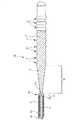
図1に示すガイドワイヤ1Aは、カテーテルに挿入して用いられるカテーテル用ガイドワイヤであって、先端側に配置された第1ワイヤ2と、第1ワイヤ2の基端側に配置された第2ワイヤ3と、螺旋状のコイル4とを有している。ガイドワイヤ1Aの全長は、特に限定されないが、200〜5000mm程度であるのが好ましい。また、ガイドワイヤ1Aの外径は、特に限定されないが、通常、0.2〜1.2mm程度であるのが好ましい。
【0033】
第1ワイヤ2は、弾性を有する線材である。第1ワイヤ2の長さは、特に限定されないが、20〜1000mm程度であるのが好ましい。
【0034】
本実施形態では、第1ワイヤ2は、先端方向へ向かって外径が漸減する外径漸減部16を有している。これにより、第1ワイヤ2の剛性(曲げ剛性、ねじり剛性)を先端方向に向かって徐々に減少させることができ、その結果、ガイドワイヤ1Aは、先端部に良好な柔軟性を得て、血管への追従性、安全性が向上すると共に、折れ曲がり等も防止することができる。
【0035】
外径漸減部16の長さ(図1中のL1で示す長さ)は、特に限定されないが、10〜1000mm程度であるのが好ましく、20〜300mm程度であるのがより好ましい。L1が前記範囲にあると、長手方向に沿った剛性の変化をより緩やか(滑らか)にすることができる。
【0036】
本実施形態では、外径漸減部16は、その外径が先端方向に向かってほぼ一定の減少率で連続的に減少するテーパ状をなしている。換言すれば、外径漸減部16のテーパ角度は、長手方向に沿ってほぼ一定になっている。これにより、本実施形態のガイドワイヤ1Aでは、長手方向に沿った剛性の変化をより緩やか(滑らか)にすることができる。なお、このような構成と異なり、外径漸減部16の先端方向に向かっての外径の減少率(外径漸減部16のテーパ角度)は、長手方向に沿って変化していても良く、例えば、外径の減少率が比較的大きい個所と比較的小さい個所とが複数回交互に繰り返して形成されているようなものでもよい。なお、その場合、外径漸減部16の先端方向に向かっての外径の減少率がゼロになる個所があってもよい。
【0037】
第1ワイヤ2の構成材料は、特に限定されず、例えば、ステンレス鋼(例えば、SUS304、SUS303、SUS316、SUS316L、SUS316J1、SUS316J1L、SUS405、SUS430、SUS434、SUS444、SUS429、SUS430F、SUS302等)、擬弾性を示す合金(超弾性合金を含む。)などの各種金属材料を使用することができるが、超弾性合金であるのが好ましい。超弾性合金は、比較的柔軟であるとともに復元性があり、曲がり癖が付き難いので、第1ワイヤ2を超弾性合金で構成することにより、ガイドワイヤ1Aは、その先端側の部分に十分な曲げに対する柔軟性と復元性が得られ、複雑に湾曲・屈曲する血管に対する追従性が向上し、より優れた操作性が得られるとともに、第1ワイヤ2が湾曲・屈曲変形を繰り返しても、第1ワイヤ2に復元性により曲がり癖が付かないので、ガイドワイヤ1Aの使用中に第1ワイヤ2に曲がり癖が付くことによる操作性の低下を防止することができる。
【0038】
擬弾性合金には、引張りによる応力−ひずみ曲線がいずれの形状のものも含み、As、Af、Ms、Mf等の変態点が顕著に測定できるものも、できないものも含み、応力により大きく変形(歪)し、応力の除去により元の形状にほぼ戻るものは全て含まれる。
【0039】
超弾性合金の好ましい組成としては、49〜52原子%NiのNi−Ti合金等のNi−Ti系合金、38.5〜41.5重量%ZnのCu−Zn合金、1〜10重量%XのCu−Zn−X合金(Xは、Be、Si、Sn、Al、Gaのうちの少なくとも1種)、36〜38原子%AlのNi−Al合金等が挙げられる。このなかでも特に好ましいものは、上記のNi−Ti系合金である。
【0040】
第1ワイヤ2の基端部には、第2ワイヤ3の先端部が連結(接続)されている。第2ワイヤ3は、弾性を有する線材である。第2ワイヤ3の長さは、特に限定されないが、20〜4800mm程度であるのが好ましい。
【0041】
第2ワイヤ3は、通常、第1ワイヤ2とは、異なる弾性率(ヤング率(縦弾性係数)、剛性率(横弾性係数)、体積弾性率)を有する材料で構成されている。このように、異なる弾性率を有するワイヤを接合して用いることにより、ガイドワイヤ1Aは、操作性に優れたものとなる。
【0042】
また、第1ワイヤおよび/または第2ワイヤは、異なる材料にて内・外層を形成する等、いわゆる複合材料にて構成され得る。このような場合においても、第1ワイヤよりも第2ワイヤの剛性のほうが高いことが好ましい。
【0043】
第2ワイヤ3の構成材料(素材)は、特に限定されず、ステンレス鋼(例えば、SUS304、SUS303、SUS316、SUS316L、SUS316J1、SUS316J1L、SUS405、SUS430、SUS434、SUS444、SUS429、SUS430F、SUS302等SUSの全品種)、ピアノ線、コバルト系合金、擬弾性合金などの各種金属材料を使用することができる。
【0044】
この中でも、コバルト系合金は、ワイヤとしたときの弾性率が高く、かつ適度な弾性限度を有している。このため、コバルト系合金で構成された第2ワイヤ3は、特に優れたトルク伝達性を有し、座屈等の問題を極めて生じ難い。コバルト系合金としては、構成元素としてCoを含むものであれば、いかなるものを用いてもよいが、Coを主成分として含むもの(Co基合金:合金を構成する元素中で、Coの含有率が重量比で最も多い合金)が好ましく、Co−Ni−Cr系合金を用いるのがより好ましい。このような組成の合金を、第2ワイヤ3の構成材料として用いることにより、前述した効果がさらに顕著なものとなる。また、このような組成の合金は、常温における変形においても可塑性を有するため、例えば、使用時等に所望の形状に容易に変形することができる。また、このような組成の合金は、弾性係数が高く、かつ高弾性限度としても冷間成形可能で、高弾性限度であることにより、座屈の発生を十分に防止しつつ、小径化することができ、所定部位に挿入するのに十分な柔軟性と剛性を備えるものとすることができる。
【0045】
Co−Ni−Cr系合金としては、例えば、28〜50wt%Co−10〜30wt%Ni−10〜30wt%Cr−残部Feの組成からなる合金や、その一部が他の元素(置換元素)で置換された合金等が好ましい。置換元素の含有は、その種類に応じた固有の効果を発揮する。例えば、置換元素として、Ti、Nb、Ta、Be、Moから選択される少なくとも1種を含むことにより、第2ワイヤ3の強度のさらなる向上等を図ることができる。なお、Co、Ni、Cr以外の元素を含む場合、その(置換元素全体の)含有量は30wt%以下であるのが好ましい。
また、Co、Ni、Crの一部は、他の元素で置換してもよい。例えば、Niの一部をMnで置換してもよい。これにより、例えば、加工性のさらなる改善等を図ることができる。また、Crの一部をMoおよび/またはWで置換してもよい。これにより、弾性限度のさらなる改善等を図ることができる。Co−Ni−Cr系合金の中でも、Moを含む、Co−Ni−Cr−Mo系合金が特に好ましい。
【0046】
Co−Ni−Cr系合金の具体的な組成としては、例えば、▲1▼40wt%Co−22wt%Ni−25wt%Cr−2wt%Mn−0.17wt%C−0.03wt%Be−残部Fe、▲2▼40wt%Co−15wt%Ni−20wt%Cr−2wt%Mn−7wt%Mo−0.15wt%C−0.03wt%Be−残部Fe、▲3▼42wt%Co−13wt%Ni−20wt%Cr−1.6wt%Mn−2wt%Mo−2.8wt%W−0.2wt%C−0.04wt%Be−残部Fe、▲4▼45wt%Co−21wt%Ni−18wt%Cr−1wt%Mn−4wt%Mo−1wt%Ti−0.02wt%C−0.3wt%Be−残部Fe、▲5▼34wt%Co−21wt%Ni−14wt%Cr−0.5wt%Mn−6wt%Mo−2.5wt%Nb−0.5wt%Ta−残部Fe等が挙げられる。本発明でいうCo−Ni−Cr系合金とはこれらの合金を包含する概念である。
【0047】
また、第2ワイヤ3の構成材料として、ステンレス鋼を用いた場合、ガイドワイヤ1Aは、より優れた押し込み性およびトルク伝達性が得られる。
【0048】
また、本発明では、第1ワイヤ2と第2ワイヤ3とを異種の合金で構成することが好ましく、また、第1ワイヤ2が、第2ワイヤ3の構成材料より弾性率が小さい材料で構成されたものであるのが好ましい。これにより、ガイドワイヤ1Aは、先端側の部分が優れた柔軟性を有するとともに、基端側の部分が剛性(曲げ剛性、ねじり剛性)に富んだものとなる。その結果、ガイドワイヤ1Aは、優れた押し込み性やトルク伝達性を得て良好な操作性を確保しつつ、先端側においては良好な柔軟性、復元性を得て血管への追従性、安全性が向上する。
【0049】
また、第1ワイヤ2と、第2ワイヤ3との具体的な組合せとしては、第1ワイヤ2を超弾性合金で構成し、第2ワイヤ3をCo−Ni−Cr系合金またはステンレス鋼で構成することが特に好ましい。これにより、前述した効果はさらに顕著なものとなる。
【0050】
なお、図示の構成では、第2ワイヤは、ほぼ全長にわたってほぼ一定の外径を有するものであるが、その長手方向に外径が変化する部位を有するものであってもよい。
【0051】
また、第1ワイヤ2を構成する超弾性合金としてNi−Ti系合金を用いることが、先端側の柔軟性と復元性の点から好ましい。
【0052】
コイル4は、線材(細線)を螺旋状に巻回してなる部材であり、第1ワイヤ2の先端側の部分を覆うように設置されている。図示の構成では、第1ワイヤ2の先端側の部分は、コイル4の内側のほぼ中心部に挿通されている。また、第1ワイヤ2の先端側の部分は、コイル4の内面と非接触で挿通されている。なお、図示の構成では、コイル4は、外力を付与しない状態で、螺旋状に巻回された線材同士の間にやや隙間が空いているが、図示と異なり、外力を付与しない状態で、螺旋状に巻回された線材同士が隙間なく密に配置されていてもよい。
【0053】
コイル4は、金属材料で構成されているのが好ましい。コイル4を構成する金属材料としては、例えば、ステンレス鋼、超弾性合金、コバルト系合金や、金、白金、タングステン等の貴金属またはこれらを含む合金等が挙げられる。特に、貴金属のようなX線不透過材料で構成した場合には、ガイドワイヤ1AにX線造影性が得られ、X線透視下で先端部の位置を確認しつつ生体内に挿入することができ、好ましい。また、コイル4は、その先端側と基端側とを異なる材料で構成しても良い。例えば、先端側をX線不透過材料のコイル、基端側をX線を比較的透過する材料(ステンレス鋼など)のコイルにて各々構成しても良い。なお、コイル4の全長は、特に限定されないが、5〜500mm程度であるのが好ましい。
【0054】
コイル4の基端部および先端部は、それぞれ、固定材料11および12により第1ワイヤ2に固定されている。また、コイル4の中間部(先端寄りの位置)は、固定材料13により第1ワイヤ2に固定されている。固定材料11、12および13は、半田(ろう材)で構成されている。なお、固定材料11、12および13は、半田に限らず、接着剤でもよい。また、コイル4の固定方法は、固定材料によるものに限らず、例えば、溶接でもよい。また、血管内壁の損傷を防止するために、固定材料12の先端面は、丸みを帯びているのが好ましい。
【0055】
本実施形態では、このようなコイル4が設置されていることにより、第1ワイヤ2は、コイル4に覆われて接触面積が少ないので、摺動抵抗を低減することができ、よって、ガイドワイヤ1Aの操作性がより向上する。
【0056】
なお、本実施形態の場合、コイル4は、線材の横断面が円形のものを用いているが、これに限らず、線材の断面が例えば楕円形、四角形(特に長方形)等のものであってもよい。
【0057】
このようなガイドワイヤ1Aでは、第1ワイヤ2と、第2ワイヤ3とは、溶接により互いに連結(固定)されている。これにより、第1ワイヤ2と第2ワイヤ3との溶接部(接続部)14は、高い結合強度(接合強度)が得られる。
【0058】
特に、本発明では、溶接部14に、外周方向に突出する突出部15が形成されている。このような突出部15が形成されることにより、第1ワイヤ2と、第2ワイヤ3との接合面積が大きくなり、これらの接合強度は、特に高いものとなる。これにより、ガイドワイヤ1Aは、第2ワイヤ3からのねじりトルクや押し込み力が確実に第1ワイヤ2に伝達される。
【0059】
また、突出部15が形成されることにより、例えば、X線透視下で、第1ワイヤ2と第2ワイヤ3との溶接部14を容易に視認することが可能となる。その結果、X線透視像を確認することにより、血管内などにおけるガイドワイヤ1A、カテーテルの進行状況を容易かつ確実に把握することができ、施術時間の短縮、安全性の向上に寄与することができる。
【0060】
なお、図示の構成では、突出部15は、その縦断面における一方側(図1中上側)およびその反対側(図1中下側)の輪郭形状がそれぞれ略円弧状をなし、突出部15の最大外径部に溶接部14が位置している。これにより、溶接部14の溶接面の面積を大きくとることができ、より高い結合強度(溶接強度)が得られるという利点がある。また、ガイドワイヤ1Aが曲げられたときに、最大外径部分に溶接部14の溶接面があるために応力が突出部15の近くの外径の小さい部分に分散されて、溶接部14に集中することがない。なお、本発明では、突出部15の形状および突出部15に対する溶接部14の位置はこれに限定されないことは、言うまでもない。
【0061】
また、上述したように、第1ワイヤ2、第2ワイヤ3は、通常、異なる弾性率を有する材料で構成されている。このため、突出部15が設けられることにより、術者が、ガイドワイヤ1Aの弾性率が比較的大きく変化する部位を容易かつ確実に認識することが可能となる。その結果、ガイドワイヤ1Aは、操作性に優れたものとなり、施術時間の短縮、安全性の向上に寄与することができる。
【0062】
また、このような突出部15が形成されると、ガイドワイヤ1Aとともに用いられるカテーテルの内壁との接触面積を小さくすることができる。これにより、ガイドワイヤ1Aとカテーテルとを相対的に移動させる際の摩擦抵抗が低減され、摺動性が向上する。その結果、カテーテル内でのガイドワイヤ1Aの操作性が良好なものとなる。
【0063】
突出部15の高さは、特に限定されないが、0.001〜0.3mmであるのが好ましく、0.01〜0.05mmであるのがより好ましい。突出部15の高さが前記下限値未満であると、第1ワイヤ2、第2ワイヤ3の構成材料などによっては、前述した効果が十分に発揮されない可能性がある。一方、突出部15の高さが前記上限値を超えると、バルーンカテーテルに挿入するルーメンの内径が決まっているので、突出部15の高さと比較して、基端側の第2ワイヤ3の外径を細くせざるを得なくなり、第2ワイヤ3の物性を十分に発揮するのが困難になる場合がある。
【0064】
本実施形態では、第1ワイヤ2の第2ワイヤ3に対する接続端面21と、第2ワイヤ3の第1ワイヤ2に対する接続端面31は、それぞれ、両ワイヤの軸方向(長手方向)にほぼ垂直な平面になっている。これにより、接続端面21、31を形成するための加工が極めて容易であり、ガイドワイヤ1Aの製造工程を複雑化することなく上記効果を達成することができる。
【0065】
なお、図示の構成と異なり、接続端面21、31は、両ワイヤの軸方向(長手方向)に垂直な平面に対し傾斜していてもよく、また、凹面または凸面になっていてもよい。
【0066】
第1ワイヤ2と、第2ワイヤ3との溶接の方法としては、特に限定されず、例えば、レーザを用いたスポット溶接、バットシーム溶接等の突き合わせ抵抗溶接などが挙げられるが、突き合わせ抵抗溶接であるのが好ましい。これにより、溶接部14は、より高い結合強度が得られる。
【0067】
以下、図2を参照して、第1ワイヤ2と第2ワイヤ3とを突き合わせ抵抗溶接の一例であるバットシーム溶接により接合する場合の手順について説明する。同図には、第1ワイヤ2と第2ワイヤ3とをバットシーム溶接により接合する場合の手順▲1▼〜▲3▼が示されている。
【0068】
手順▲1▼では、図示しないバット溶接機に固定(装着)された第1ワイヤ2と第2ワイヤ3とが示される。
【0069】
手順▲2▼にて、第1ワイヤ2と第2ワイヤ3とは、バット溶接機によって、所定の電圧を印加されながら第1ワイヤ2の基端側の接続端面21と第2ワイヤ3の先端側の接続端面31とが加圧接触される。この加圧接触により、接触部分には溶融層(溶接面)が形成され、第1ワイヤ2と第2ワイヤ3とは強固に接続される。この際、溶接部14に、外周方向に突出した突出部15が形成される。突出部15の大きさ(高さ)は、例えば、印加電圧や、第1ワイヤ2と第2ワイヤ3との押し付け圧力などを調節することにより、コントロールすることができる。また、突出部15の大きさ(高さ)は、研磨などにより調整してもよい。
【0070】
次いで、手順▲3▼にて、第1ワイヤ2の先端側を研磨して外径が先端方向に向かって漸減する外径漸減部16を形成する。
【0071】
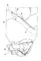
図3および図4は、それぞれ、本発明のガイドワイヤ1AをPTCA術に用いた場合における使用状態を示す図である。
【0072】
図3および図4中、符号40は大動脈弓、符号50は心臓の右冠状動脈、符号60は右冠状動脈開口部、符号70は血管狭窄部である。また、符号30は大腿動脈からガイドワイヤ1Aを確実に右冠状動脈に導くためのガイディングカテーテル、符号20はその先端部分に拡張・収縮自在なバルーン201を有する狭窄部拡張用のバルーンカテーテルである。
【0073】
図3に示すように、ガイドワイヤ1Aの先端をガイディングカテーテル30の先端から突出させ、右冠状動脈開口部60から右冠状動脈50内に挿入する。さらに、ガイドワイヤ1Aを進め、先端から右冠状動脈内に挿入し、先端が血管狭窄部70を超えた位置で停止する。これにより、バルーンカテーテル20の通路が確保される。なお、このとき、ガイドワイヤ1Aの溶接部14は、大動脈弓40の基部付近(生体内)に位置している。
【0074】
次に、図4に示すように、ガイドワイヤ1Aの基端側から挿通されたバルーンカテーテル20の先端をガイディングカテーテル30の先端から突出させ、さらにガイドワイヤ1Aに沿って進め、右冠状動脈開口部60から右冠状動脈50内に挿入し、バルーンが血管狭窄部70の位置に到達したところで停止する。
【0075】
次に、バルーンカテーテル20の基端側からバルーン拡張用の流体を注入して、バルーン201を拡張させ、血管狭窄部70を拡張する。このようにすることによって、血管狭窄部70の血管に付着堆積しているコレステロール等の堆積物は物理的に押し広げられ、血流阻害が解消できる。
【0076】
<第2実施形態>
図5は、本発明のガイドワイヤの第2実施形態を示す縦断面図である。以下、この図を参照して本発明のガイドワイヤの第2実施形態について説明するが、前述した実施形態との相違点を中心に説明し、同様の事項についてはその説明を省略する。
【0077】
本実施形態のガイドワイヤ1Bは、外径漸減部16が第2ワイヤ3に形成されており、第1ワイヤ2は、突出部15を除いて、ほぼ全長に渡りほぼ一定の外径を有している。すなわち、ガイドワイヤ1Bでは、溶接部14より基端側に外径漸減部16が設けられている。
【0078】
また、本実施形態のガイドワイヤ1Bでは、コイル4が、その基端側で突出部15に当接するように配されている。
【0079】
<第3実施形態>
図6は、本発明のガイドワイヤの第3実施形態を示す縦断面図である。以下、この図を参照して本発明のガイドワイヤの第3実施形態について説明するが、前述した実施形態との相違点を中心に説明し、同様の事項についてはその説明を省略する。
【0080】
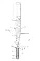
本実施形態のガイドワイヤ1Fでは、第1ワイヤ2が、外径漸減部16と該外径漸減部16より基端側に設けられた外径漸減部18とを有している。このように、第1ワイヤ2(第2ワイヤ3)には、複数の部位に外径漸減部が形成されていてもよい。
【0081】
また、本実施形態のガイドワイヤ1Fでは、第2ワイヤ3が、その先端付近に外径漸減部16’を有している。すなわち、第2ワイヤ3は、その先端部付近に設けられた第1の部位と、該第1の部位より基端側に設けられかつ第1の部位よりも剛性の高い第2の部位とを有する。ガイドワイヤ1Fにおいては、外径漸減部16’が第1の部位を構成する。これにより、第1ワイヤ2と第2ワイヤ3との弾性移行が滑らかに変化するという効果が得られる。また、該第1の部位として外径漸減部16’の先端側に外径一定部を設けて外径漸減部16’と外径一定部とをあわせて第1の部位としてもよい。当該外径一定部は、第1ワイヤ2とほぼ同じ剛性を有することが好ましい。
【0082】
また、本実施形態のガイドワイヤ1Fでは、その外表面(外周面)側に、被覆層7を有している。このように、本発明のガイドワイヤは、その外表面(外周面)の全部または一部を覆う被覆層を有するものであってもよい。このような被覆層7は、種々の目的で形成することができるが、その一例として、ガイドワイヤ1Fの摩擦(摺動摩擦)を低減し、摺動性を向上させることによってガイドワイヤ1Fの操作性を向上させることがある。
【0083】
このような目的のためには、被覆層7は、摩擦を低減し得る材料で構成されているのが好ましい。これにより、ガイドワイヤ1Fとともに用いられるカテーテルの内壁との摩擦抵抗(摺動抵抗)が低減されて摺動性が向上し、カテーテル内でのガイドワイヤ1Fの操作性がより良好なものとなる。また、ガイドワイヤ1Fの摺動抵抗が低くなることで、ガイドワイヤ1Fをカテーテル内で移動および/または回転した際に、ガイドワイヤ1Fのキンク(折れ曲がり)やねじれ、特に溶接部付近におけるキンクやねじれをより確実に防止することができる。
【0084】
このような摩擦を低減し得る材料としては、例えば、ポリエチレン、ポリプロピレン等のポリオレフィン、ポリ塩化ビニル、ポリエステル(PET、PBT等)、ポリアミド、ポリイミド、ポリウレタン、ポリスチレン、ポリカーボネート、シリコーン樹脂、フッ素系樹脂(PTFE、ETFE等)、シリコーンゴム、その他各種のエラストマー(例えば、ポリアミド系、ポリエステル系等の熱可塑性エラストマー)またはこれらの複合材料が挙げられるが、そのなかでも特に、フッ素系樹脂(またはこれを含む複合材料)が好ましく、PTFEがより好ましい。
【0085】
また、摩擦を低減し得る材料の他の好ましい例としては、親水性材料または疎水性材料が挙げられる。これらのうちでも特に、親水性材料が好ましい。
【0086】
この親水性材料としては、例えば、セルロース系高分子物質、ポリエチレンオキサイド系高分子物質、無水マレイン酸系高分子物質(例えば、メチルビニルエーテル−無水マレイン酸共重合体のような無水マレイン酸共重合体)、アクリルアミド系高分子物質(例えば、ポリアクリルアミド、ポリグリシジルメタクリレート−ジメチルアクリルアミド(PGMA−DMAA)のブロック共重合体)、水溶性ナイロン、ポリビニルアルコール、ポリビニルピロリドン等が挙げられる。
【0087】
このような親水性材料は、多くの場合、湿潤(吸水)により潤滑性を発揮し、ガイドワイヤ1Fとともに用いられるカテーテルの内壁との摩擦抵抗(摺動抵抗)を低減する。これにより、ガイドワイヤ1Fの摺動性が向上し、カテーテル内でのガイドワイヤ1Fの操作性がより良好なものとなる。
【0088】
このような被覆層7の形成箇所は、ガイドワイヤ1Fの全長でも、長手方向の一部でもよいが、溶接部14を覆うように、すなわち溶接部14を含む箇所に形成されているのが好ましい。
【0089】
被覆層7は、外径漸減部16’および突出部15を被覆して、実質的に均一な外径になっている。なお、使用上支障のないようななだらかな外径の変化も「実質的に均一な外径」に含むものとする。
【0090】
被覆層7の厚さは、特に限定されないが、通常は、厚さ(平均)が1〜20μm程度であるのが好ましく、2〜10μm程度であるのがより好ましい。被覆層7の厚さが薄すぎると、被覆層7の形成目的が十分に発揮されないことがあり、また、被覆層7の剥離が生じるおそれがあり、また、被覆層7の厚さが厚すぎると、ワイヤの物性を阻害することがあり、また被覆層7の剥離が生じるおそれがある。
【0091】
なお、本発明では、ガイドワイヤ本体(第1ワイヤ2、第2ワイヤ3、コイル4等)の外周面(表面)に、被覆層7の密着性を向上するための処理(化学処理、熱処理等)を施したり、被覆層7の密着性を向上し得る中間層を設けたりすることもできる。
【0092】
また、被覆層7は、各部位でほぼ一定の組成を有するものであってもよいし、異なる組成を有するものであってもよい。例えば、被覆層7は、少なくともコイル4を被覆する領域(第1被覆層)と、該領域より基端側の領域(第2被覆層)とで、構成材料が異なるものであってもよい。具体的には、第1被覆層が親水性材料にて構成され、第2被覆層が疎水性材料にて構成されるものであってもよい。また、第1被覆層、第2被覆層は、図示のように、両者が長手方向に連続して形成されたものであってもよいが、第1被覆層の基端と第2被覆層の先端とが離間していてもよく、あるいは、第1被覆層と第2被覆層とが部分的に重なっていてもよい。
【0093】
なお、このような被覆層(親水性材料または疎水性材料による被膜を含む)は、例えば、前述したような第1、第2実施形態のガイドワイヤ等に設けられるものであってもよい。
【0094】
以上、本発明のガイドワイヤを図示の実施形態について説明したが、本発明は、これに限定されるものではなく、ガイドワイヤを構成する各部は、同様の機能を発揮し得る任意の構成のものと置換することができる。また、任意の構成物が付加されていてもよい。
【0095】
例えば、本発明では、図7、図8に示すガイドワイヤ(ガイドワイヤ1C、1D)のように、溶接部14以外の部位に、外周方向に突出する他の突出部(突出部15以外の突出部)17を有していてもよい。このような突出部17が形成されることにより、例えば、ガイドワイヤとともに用いられるカテーテルの内壁との接触面積をさらに小さくすることができる。これにより、ガイドワイヤとカテーテルとを相対的に移動させる際の摩擦抵抗が低減され、摺動性はさらに向上する。その結果、カテーテル内でのガイドワイヤの操作性は特に良好なものとなる。
【0096】
また、前述の実施形態では、2つのワイヤ(第1ワイヤ2と第2ワイヤ3)の接合部を、1ヶ所にのみ有する構成について説明したが、接合部は、2ヶ所以上に形成されるものであってもよい。すなわち、本発明では、ガイドワイヤは、第1ワイヤ、第2ワイヤ以外のワイヤを有するものであってもよい。例えば、図9に示すガイドワイヤ1Eのように、第2ワイヤ3の基端側に、第3ワイヤ5を有するものであってもよい。これにより、ガイドワイヤの長手方向の各部位において、弾性等の特性をより詳細に設定することができ、ガイドワイヤ全体としての操作性をさらに向上させることが可能となる。
【0097】
このガイドワイヤ1Eでは、第2ワイヤ3と第3ワイヤ5とが前記と同様の溶接部14を介して接合されており、この溶接部14には、好ましくは前述した突出部15と同様の突出部17が形成されている。
【0098】
また、前述した各実施形態では、溶接部14は、コイル4の基端よりも基端側に位置しているものとして説明したが、溶接部14がコイル4の基端よりも先端側に位置していても良い。
【0099】
本発明において、溶接部14に形成される突出部15は、種々の形状のものが挙げられる。以下、突出部15(または17)の形状の例について、図10〜図13を参照しつつ説明する。
【0100】
図10に示す突出部15は、縦断面における一方側(図中上方)およびその反対側(図中下方)の輪郭形状がそれぞれ台形をなすものである。すなわち、前述した各実施形態では、突出部15は、縦断面における一方側およびその反対側の輪郭形状がそれぞれ凸状に湾曲した略円弧状をなすものであるが、本発明では、これらの形状は、例えば、台形、三角形等の非円形(非円弧形状)でもよい。
【0101】
図10に示す形状では、突出部15の溶接部14付近、すなわち溶接部14を挟んでその基端側近傍および先端側近傍の領域(前記台形の上底に相当する部位)は、その外径がほぼ一定である。そして、この外径がほぼ一定の領域のほぼ中央に溶接部14が位置している。溶接部14は、突出部15の最も外径の大きい部分に位置している。このような構成とすることにより、溶接部14への応力集中を防止または緩和することができ、第2ワイヤ3から第1ワイヤ2へねじりトルクや押し込み力が作用した際に、溶接部14への応力集中による溶接部14の破損をより確実に防止することができる。
【0102】
なお、前述の外径がほぼ一定の領域に替えて、なだらかな円弧状であってもよい。
【0103】
図11〜図13に示す突出部15は、いずれも、溶接部14の溶接面(接続端面21、31)を境に基端側と先端側とが非対称の形状をなしている。
【0104】
図11に示す突出部15は、溶接部14の溶接面より先端側(第1ワイヤ2側)は、その縦断面における一方側およびその反対側の輪郭形状がそれぞれ前記各実施形態と同様の略円弧状をなし、溶接部14の溶接面より基端側(第2ワイヤ3側)は、その縦断面における一方側およびその反対側の輪郭形状がそれぞれ溶接部14から基端方向に向かってなだらかにかつ凹状に湾曲した湾曲形状をなしている。また、溶接部14は、突出部15の最も外径の大きい部分に位置している。
【0105】
このような構成とすることにより、剛性の移行がなだらかになるとともに、溶接部14の基端側部分への応力集中を防止または緩和することができ、第2ワイヤ3から第1ワイヤ2へねじりトルクや押し込み力が作用した際に、応力集中による当該部分の破損、変形等をより確実に防止することができる。
【0106】
図12に示す突出部15は、前記図11とは逆であり、溶接部14の溶接面より基端側(第2ワイヤ3側)は、その縦断面における一方側およびその反対側の輪郭形状がそれぞれ前記各実施形態と同様の略円弧状をなし、溶接部14の溶接面より先端側(第1ワイヤ2側)は、その縦断面における一方側およびその反対側の輪郭形状がそれぞれ溶接部14から先端方向に向かってなだらかにかつ凹状に湾曲した湾曲形状をなしている。また、溶接部14は、突出部15の最も外径の大きい部分に位置している。
【0107】
このような構成とすることにより、溶接部14の先端側部分への応力集中を防止または緩和することができ、第2ワイヤ3から第1ワイヤ2へねじりトルクや押し込み力が作用した際に、応力集中による当該部分の破損、変形等をより確実に防止することができる。
【0108】
もちろん、突出部15は、溶接部14の溶接面より先端側および基端側のいずれもが、その縦断面における一方側およびその反対側の輪郭形状がそれぞれ溶接部14から離間する方向に向かってなだらかにかつ凹状に湾曲した湾曲形状をなすものでもよい。
【0109】
図13に示す突出部15は、その全体形状は、前記各実施形態と同様の略円弧状をなすが、この突出部15内において、溶接部14の溶接面が基端側(第2ワイヤ3側)に偏った位置にある。なお、これとは逆に、突出部15内において、溶接部14の溶接面が先端側(第1ワイヤ2側)に偏った位置にあってもよい。
【0110】
このような構成とすることにより、溶接部14の溶接面が突出部15の軸方向中央部とならず、すなわち、溶接部14の溶接面が突出部15の最大外径部から外れた位置となるので、溶接部14への応力集中を防止または緩和することができ、よって、第2ワイヤ3から第1ワイヤ2へねじりトルクや押し込み力が作用した際に、溶接部14への応力集中による溶接部14の破損をより確実に防止することができる。
【0111】
なお、上述したような溶接部14の溶接面が突出部15内で基端側または先端側に偏った位置にある構成は、例えば図10に示すような、突出部15の縦断面における一方側およびその反対側の輪郭形状が非円形(非円弧形状)のものについても適用することができる。
【0112】
以上のように、突出部15を、溶接部14の溶接面を境に基端側と先端側とが非対称の形状とすることにより、溶接部14への応力集中を防止または緩和することができ、第2ワイヤ3から第1ワイヤ2へねじりトルクや押し込み力が作用した際に、溶接部14への応力集中による溶接部14の破損をより確実に防止することができるという優れた効果が発揮される。
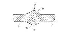
【0113】
図14には、溶接部付近のさらに他の構成例が示されている。同図に示すように、第1ワイヤ2と第2ワイヤ3との連結部(溶接部14)付近は、他所よりも細径化されており、この細径部19の長手方向の途中に溶接部14および突出部15が形成されている。
【0114】
このような構成とすることにより、溶接部14への応力集中を防止または緩和することができ、第2ワイヤ3から第1ワイヤ2へねじりトルクや押し込み力が作用した際に、溶接部14への応力集中による溶接部14の破損をより確実に防止することができる。
【0115】
ここで、突出部15の最大外径は、細径部19より基端側または先端側の部位の外径に比べ、ほぼ等しいかまたはそれ以下であるのが好ましい。これにより、カテーテルに対するガイドワイヤの移動をより円滑に行うことができる。
【0116】
なお、図14に示す構成では、突出部15の形状は、図10に示すものとほぼ等しいが、これに限らず、例えば図1または図5〜図13のいずれかに示す形状を適用してもよい。
【0117】
また、以上のような図11〜図14に示す構成は、前述した各実施形態のうちのいずれの実施形態に対し適用されてもよい。特に、図6に示す実施形態では、突出部17に対し図11〜図14に示す構成を適用することもできる。
【0118】
【発明の効果】
以上述べたように、本発明によれば、先端側に配置された第1ワイヤと、第1ワイヤの基端側に配置された第2ワイヤとを設けたことにより、操作性に優れたガイドワイヤを提供することができる。特に、柔軟性に優れた第1ワイヤと、第1ワイヤより弾性率の大きい材料で構成された第2ワイヤとを設けたことにより、柔軟性に優れた先端部と剛性に富んだ基端部とを有し、押し込み性、トルク伝達性および追従性に優れたガイドワイヤが構成できる。
【0119】
また、第1ワイヤと第2ワイヤとを溶接により連結し、この溶接部に突出部を形成したことにより、連結部(溶接部)の結合強度が高く、第2ワイヤから第1ワイヤへねじりトルクや押し込み力を確実に伝達することができる。
【0120】
また、突出部を有することにより、X線透視下で、第1ワイヤと第2ワイヤとの溶接部を容易に視認することが可能となる。ガイドワイヤ、カテーテルの操作性が向上し、施術時間の短縮、安全性の向上に寄与することができる。
【0121】
また、突出部を有することにより、ガイドワイヤとともに用いられるカテーテルの内壁との接触面積を小さくすることができる。これにより、ガイドワイヤとカテーテルとを相対的に移動させる際の摩擦抵抗が低減され、摺動性が向上する。その結果、カテーテル内でのガイドワイヤの操作性が良好なものとなる。
【0122】
また、被覆層が摩擦を低減し得る材料で構成されている場合には、カテーテル内などにおけるガイドワイヤの摺動性が向上し、ガイドワイヤの操作性をより良好なものとすることができる。ガイドワイヤの摺動抵抗が低くなることで、ガイドワイヤのキンク(折れ曲がり)やねじれ、特に溶接部付近におけるキンクやねじれをより確実に防止することができる。
【0123】
また、各部位で、被覆層の構成材料を変更すること等により、部分的に摺動抵抗を高めた部位を設けることができ、術者においては、ガイドワイヤの汎用性が広くなる。
【図面の簡単な説明】
【図1】本発明のガイドワイヤの第1実施形態を示す縦断面図である。
【図2】図1に示すガイドワイヤにおける第1ワイヤと第2ワイヤとを接続する手順を示す図である。
【図3】本発明のガイドワイヤの使用例を説明するための模式図である。
【図4】本発明のガイドワイヤの使用例を説明するための模式図である。
【図5】本発明のガイドワイヤの第2実施形態を示す縦断面図である。
【図6】本発明のガイドワイヤの第3実施形態を示す縦断面図である。
【図7】本発明のガイドワイヤの他の実施形態を示す縦断面図である。
【図8】本発明のガイドワイヤの他の実施形態を示す縦断面図である。
【図9】本発明のガイドワイヤの他の実施形態を示す縦断面図である。
【図10】本発明のガイドワイヤにおける突出部の形状の例を示す縦断面図である。
【図11】本発明のガイドワイヤにおける突出部の形状の例を示す縦断面図である。
【図12】本発明のガイドワイヤにおける突出部の形状の例を示す縦断面図である。
【図13】本発明のガイドワイヤにおける突出部の形状の例を示す縦断面図である。
【図14】本発明のガイドワイヤにおける溶接部付近の形状の例を示す縦断面図である。
【符号の説明】
1A〜1F ガイドワイヤ
2 第1ワイヤ
21 接続端面
3 第2ワイヤ
31 接続端面
4 コイル
5 第3ワイヤ
7 被覆層
11、12、13 固定材料
14 溶接部
15 突出部
16、16’ 外径漸減部
17 突出部
18 外径漸減部
19 細径部
20 バルーンカテーテル
201 バルーン
30 ガイディングカテーテル
40 大動脈弓
50 右冠状動脈
60 右冠状動脈開口部
70 血管狭窄部[0001]
TECHNICAL FIELD OF THE INVENTION
The present invention relates to a guidewire, particularly to a guidewire used for introducing a catheter into a body cavity such as a blood vessel.
[0002]
[Prior art]
The guide wire is used for treatment of a site where surgery is difficult, such as PTCA (Percutaneous Transluminal Coronary Angioplasty), treatment for the purpose of minimally invasive to the human body, and treatment of the heart. It is used to guide catheters used for examinations such as angiography. The guide wire used in the PTCA operation is inserted into the vicinity of a target vascular stenosis together with the balloon catheter with the distal end of the guide wire protruding from the distal end of the balloon catheter. Guide to nearby.
[0003]
The blood vessels are complicatedly curved, and the guide wire used when inserting the balloon catheter into the blood vessels has flexibility and resilience to moderate bending, and pushability to transmit the operation at the proximal end to the distal side. And torque transmission properties (collectively referred to as “operability”), as well as kink resistance (bending resistance) and the like. Among these properties, as a structure for obtaining a moderate flexibility, a structure with a metal coil that has flexibility against bending around a thin tip core material of a guide wire, and for imparting flexibility and resilience There is a guide wire using a super-elastic wire such as Ni-Ti as a core material.
[0004]
In a conventional guide wire, a core material is substantially composed of one kind of material. In order to enhance the operability of the guide wire, a material having a relatively high elastic modulus is used. Has lost flexibility. If a material having a relatively low elastic modulus is used to obtain the flexibility of the distal end portion of the guide wire, the operability at the proximal end side of the guide wire is lost. Thus, it has been difficult to satisfy the required flexibility and operability with one kind of core material.
[0005]
In order to improve such a defect, for example, a Ni—Ti alloy wire is used as a core material, and heat treatment is performed on the distal side and the proximal side under different conditions to increase the flexibility of the distal end and increase the flexibility of the proximal side. A guide wire with increased rigidity has been proposed (for example, see Patent Document 1). However, there is a limit to the control of flexibility by such heat treatment, and even if sufficient flexibility is obtained at the distal end, satisfactory rigidity may not always be obtained at the proximal end.
[0006]
[Patent Document 1]
JP-A-63-171570
[0007]
[Problems to be solved by the invention]
SUMMARY OF THE INVENTION An object of the present invention is to provide a guide wire having a high joint strength between a first wire on the distal end side and a second wire on the proximal end side and excellent operability.
[0008]
[Means for Solving the Problems]
Such an object is achieved by the present invention of the following (1) to (6), (20), and (21). Further, (7) to (19) are preferable.
[0009]
(1) a linear first wire disposed on the distal end side;
A second linear wire disposed on the proximal end side of the first wire,
The first wire and the second wire are connected by welding,
A guide wire characterized in that the welding portion has a protruding portion protruding in an outer peripheral direction.
[0010]
(2) a linear first wire disposed on the distal end side;
A second wire that is disposed on the base end side of the first wire and has a higher rigidity than the first wire;
The first wire and the second wire are connected by welding,
This weld has a projection projecting in the outer peripheral direction,
The second wire has a first portion provided in the vicinity of a distal end thereof, and a second portion provided on a base end side of the first portion,
The first portion has a lower rigidity than the second portion.
[0011]
(3) The guide wire according to the above (1) or (2), further comprising a coating layer provided so as to cover at least the welded portion.
[0012]
(4) The guide wire according to any one of (1) to (3), wherein the protruding portion is visible under X-ray fluoroscopy.
[0013]
(5) The guide wire according to any one of (1) to (4), further including a spiral coil that covers at least a portion of the first wire on the distal end side.
[0014]
(6) The guide wire according to (5), wherein the coil has a base end in contact with the protruding portion.
[0015]
(7) The guide wire according to any one of (1) to (6), wherein a height of the protrusion is 0.01 to 0.3 mm.
[0016]
(8) The guide wire according to any one of (1) to (7), wherein the welding is performed by butt resistance welding.
[0017]
(9) The guide wire according to any one of (1) to (8), wherein a connection end face between the first wire and the second wire is substantially perpendicular to an axial direction of both wires.
[0018]
(10) The guide wire according to any one of (1) to (9), further including an outer diameter gradually decreasing portion in which an outer diameter gradually decreases in a distal direction.
[0019]
(11) The guidewire according to the above (10), wherein the outer diameter is gradually reduced at a distal end side of the welded portion.
[0020]
(12) The guidewire according to (10) or (11), wherein the outer diameter is gradually reduced at a base end side of the welded portion.
[0021]
(13) The guide wire according to any of (1) to (12), wherein the first wire has a substantially constant outer diameter over substantially the entire length except for the protruding portion.
[0022]
(14) The guide wire according to any one of (1) to (13), wherein the first wire is formed of a material having a lower elastic modulus than a constituent material of the second wire.
[0023]
(15) The guide wire according to any one of (1) to (14), wherein the first wire is made of a superelastic alloy.
[0024]
(16) The guide wire according to any one of (1) to (15), wherein the second wire is made of stainless steel.
[0025]
(17) The guide wire according to any one of (1) to (15), wherein the second wire is made of a Co-based alloy.
[0026]
(18) The guide wire according to (17), wherein the Co-based alloy is a Co-Ni-Cr-based alloy.
[0027]
(19) The guide wire according to any one of (1) to (18), further including at least one other protruding portion that protrudes in an outer peripheral direction in a portion other than the welded portion.
[0028]
(20) The guide wire according to any one of (1) to (19), wherein the protruding portion has an asymmetric shape on a base end side and a distal end side with respect to a welding surface of the welding portion.
[0029]
(21) Any one of the above (1) to (20), wherein the vicinity of the welded portion between the first wire and the second wire is reduced in diameter, and the protrusion is formed in the reduced diameter portion. A guidewire according to claim 1.
[0030]
BEST MODE FOR CARRYING OUT THE INVENTION
Hereinafter, a guidewire of the present invention will be described in detail based on a preferred embodiment shown in the accompanying drawings.
[0031]
<First embodiment>
FIG. 1 is a longitudinal sectional view showing a first embodiment of a guide wire according to the present invention, and FIG. 2 is a view showing a procedure for connecting a first wire and a second wire in the guide wire shown in FIG. For convenience of explanation, the right side in FIG. 1 is referred to as a “base end” and the left side is referred to as a “distal end”. Also, in FIGS. 1 and 2, the length direction of the guide wire is shortened to make it easier to see, and the thickness direction of the guide wire is schematically illustrated in an exaggerated manner. Is significantly different from the actual one (the same applies to FIGS. 5 to 9 described later).
[0032]
A
[0033]
The
[0034]
In the present embodiment, the
[0035]
The length of the outer diameter gradually decreasing portion 16 (L in FIG. 1)1 Is not particularly limited, but is preferably about 10 to 1000 mm, and more preferably about 20 to 300 mm. L1 Is in the above range, the change in rigidity along the longitudinal direction can be made more gradual (smooth).
[0036]
In the present embodiment, the outer diameter gradually decreasing
[0037]
The constituent material of the
[0038]
Pseudoelastic alloys include those having a stress-strain curve due to tension in any shape, including those in which transformation points such as As, Af, Ms, and Mf can be remarkably measured and those in which they cannot be measured. (Strain) and almost all return to the original shape by removing the stress are included.
[0039]
Preferred compositions of the superelastic alloy include a Ni-Ti alloy such as a 49-52 atomic% Ni-Ni alloy, a 38.5-41.5 wt% Zn Cu-Zn alloy, and a 1-10 wt% X (X is at least one of Be, Si, Sn, Al, and Ga), and a 36-38 atomic% Al-Ni-Al alloy. Of these, particularly preferred are the above-mentioned Ni-Ti alloys.
[0040]
The distal end of the
[0041]
The
[0042]
Further, the first wire and / or the second wire may be formed of a so-called composite material such as forming inner and outer layers with different materials. Even in such a case, it is preferable that the rigidity of the second wire is higher than that of the first wire.
[0043]
The constituent material (material) of the
[0044]
Among them, the cobalt-based alloy has a high elastic modulus when used as a wire and has an appropriate elastic limit. For this reason, the
[0045]
Examples of the Co-Ni-Cr-based alloy include an alloy having a composition of 28 to 50 wt% Co-10 to 30 wt% Ni-10 to 30 wt% Cr and the balance of Fe, and a part of the alloy is another element (substitution element). Are preferred. The inclusion of the substitution element exerts a specific effect according to the type. For example, by including at least one selected from Ti, Nb, Ta, Be, and Mo as a substitution element, the strength of the
Further, a part of Co, Ni, and Cr may be replaced with another element. For example, part of Ni may be replaced by Mn. Thereby, for example, the workability can be further improved. Further, a part of Cr may be replaced with Mo and / or W. As a result, the elastic limit can be further improved. Among the Co-Ni-Cr alloys, a Co-Ni-Cr-Mo alloy containing Mo is particularly preferable.
[0046]
The specific composition of the Co-Ni-Cr alloy is, for example, (1) 40 wt% Co-22 wt% Ni-25 wt% Cr-2 wt% Mn-0.17 wt% C-0.03 wt% Be-balance Fe (2) 40 wt% Co-15 wt% Ni-20 wt% Cr-2 wt% Mn-7 wt% Mo-0.15 wt% C-0.03 wt% Be- balance Fe, (3) 42 wt% Co-13 wt% Ni- 20 wt% Cr-1.6 wt% Mn-2 wt% Mo-2.8 wt% W-0.2 wt% C-0.04 wt% Be-balance Fe, (4) 45 wt% Co-21 wt% Ni-18 wt% Cr- 1 wt% Mn-4 wt% Mo-1 wt% Ti-0.02 wt% C-0.3 wt% Be-balance Fe, (5) 34 wt% Co-21 wt% Ni-14 wt% Cr-0.5 wt% Mn-6w % Mo-2.5wt% Nb-0.5wt% Ta- balance being Fe, and the like. The Co-Ni-Cr-based alloy referred to in the present invention is a concept that includes these alloys.
[0047]
Further, when stainless steel is used as a constituent material of the
[0048]
In the present invention, it is preferable that the
[0049]
Further, as a specific combination of the
[0050]
In the illustrated configuration, the second wire has a substantially constant outer diameter over substantially the entire length, but may have a portion whose outer diameter changes in the longitudinal direction.
[0051]
It is preferable to use a Ni-Ti alloy as the superelastic alloy constituting the
[0052]
The coil 4 is a member formed by spirally winding a wire (thin wire), and is installed so as to cover a portion of the
[0053]
The coil 4 is preferably made of a metal material. Examples of the metal material forming the coil 4 include stainless steel, superelastic alloys, cobalt-based alloys, noble metals such as gold, platinum, and tungsten, and alloys containing these. In particular, when the
[0054]
The proximal end and the distal end of the coil 4 are fixed to the
[0055]
In the present embodiment, since such a coil 4 is provided, the
[0056]
In the present embodiment, the coil 4 has a wire having a circular cross section. However, the present invention is not limited to this. For example, the wire has a cross section of an ellipse, a square (especially a rectangle), or the like. Is also good.
[0057]
In such a
[0058]
In particular, in the present invention, the
[0059]
In addition, by forming the protruding
[0060]
In the configuration shown in the drawing, the protruding
[0061]
Further, as described above, the
[0062]
Further, when such a projecting
[0063]
The height of the
[0064]
In the present embodiment, the connection end face 21 of the
[0065]
Note that, unlike the configuration shown in the figure, the connection end surfaces 21 and 31 may be inclined with respect to a plane perpendicular to the axial direction (longitudinal direction) of both wires, or may be concave or convex.
[0066]
The method for welding the
[0067]
Hereinafter, a procedure for joining the
[0068]
In procedure (1), the
[0069]
In procedure (2), the
[0070]
Next, in step (3), the distal end of the
[0071]
FIG. 3 and FIG. 4 are views showing a use state when the
[0072]
3 and 4,
[0073]
As shown in FIG. 3, the distal end of the
[0074]
Next, as shown in FIG. 4, the distal end of the
[0075]
Next, a balloon expansion fluid is injected from the proximal end side of the
[0076]
<Second embodiment>
FIG. 5 is a longitudinal sectional view showing a second embodiment of the guide wire of the present invention. Hereinafter, a second embodiment of the guidewire of the present invention will be described with reference to this drawing, but the description will be focused on the differences from the above-described embodiment, and the description of the same matters will be omitted.
[0077]
In the guide wire 1B of the present embodiment, the outer diameter gradually decreasing
[0078]
Further, in the guide wire 1B of the present embodiment, the coil 4 is disposed so as to abut on the protruding
[0079]
<Third embodiment>
FIG. 6 is a longitudinal sectional view showing a third embodiment of the guide wire of the present invention. Hereinafter, a third embodiment of the guidewire of the present invention will be described with reference to this drawing, but the description will focus on the differences from the above-described embodiment, and the description of the same items will be omitted.
[0080]
In the guide wire 1F of the present embodiment, the
[0081]
Further, in the guide wire 1F of the present embodiment, the
[0082]
Further, the guide wire 1F of the present embodiment has the coating layer 7 on the outer surface (outer peripheral surface) side. Thus, the guidewire of the present invention may have a coating layer that covers all or a part of the outer surface (outer peripheral surface). Such a coating layer 7 can be formed for various purposes. As an example, the operability of the guide wire 1F is reduced by reducing the friction (sliding friction) of the guide wire 1F and improving the slidability. May be improved.
[0083]
For such a purpose, the coating layer 7 is preferably made of a material capable of reducing friction. Thereby, the frictional resistance (sliding resistance) with the inner wall of the catheter used together with the guidewire 1F is reduced, the slidability is improved, and the operability of the guidewire 1F inside the catheter is further improved. In addition, since the sliding resistance of the guide wire 1F is reduced, when the guide wire 1F is moved and / or rotated in the catheter, the guide wire 1F is kinked (bent) or twisted, particularly, kink or twisted near a welded portion. Can be more reliably prevented.
[0084]
Examples of materials capable of reducing such friction include polyolefins such as polyethylene and polypropylene, polyvinyl chloride, polyesters (PET, PBT and the like), polyamides, polyimides, polyurethanes, polystyrenes, polycarbonates, silicone resins, fluorine resins ( PTFE, ETFE, etc.), silicone rubber, various other elastomers (for example, thermoplastic elastomers such as polyamide-based and polyester-based) or composite materials thereof. (Composite material) is preferred, and PTFE is more preferred.
[0085]
Another preferable example of the material capable of reducing friction includes a hydrophilic material or a hydrophobic material. Among these, hydrophilic materials are particularly preferable.
[0086]
Examples of the hydrophilic material include a cellulose-based polymer, a polyethylene oxide-based polymer, and a maleic anhydride-based polymer (eg, a maleic anhydride copolymer such as a methyl vinyl ether-maleic anhydride copolymer). ), Acrylamide-based polymer substances (eg, polyacrylamide, polyglycidyl methacrylate-dimethylacrylamide (PGMA-DMAA) block copolymer), water-soluble nylon, polyvinyl alcohol, and polyvinylpyrrolidone.
[0087]
Such a hydrophilic material often exhibits lubricity by wetting (water absorption) and reduces frictional resistance (sliding resistance) with the inner wall of a catheter used with the guidewire 1F. Thereby, the slidability of the guidewire 1F is improved, and the operability of the guidewire 1F in the catheter is further improved.
[0088]
The formation location of such a coating layer 7 may be the entire length of the guide wire 1F or a part in the longitudinal direction, but is preferably formed so as to cover the
[0089]
The coating layer 7 has a substantially uniform outer diameter by covering the outer diameter gradually decreasing
[0090]
The thickness of the coating layer 7 is not particularly limited, but usually, the thickness (average) is preferably about 1 to 20 μm, and more preferably about 2 to 10 μm. If the thickness of the coating layer 7 is too thin, the purpose of forming the coating layer 7 may not be sufficiently exhibited, and the coating layer 7 may be peeled off, and the thickness of the coating layer 7 is too thick. If so, the physical properties of the wire may be impaired, and the coating layer 7 may be peeled off.
[0091]
In the present invention, a treatment (chemical treatment, heat treatment, or the like) for improving the adhesion of the coating layer 7 to the outer peripheral surface (surface) of the guide wire body (the
[0092]
In addition, the coating layer 7 may have a substantially constant composition at each portion, or may have a different composition. For example, the constituent material of the coating layer 7 may be different between at least a region (first coating layer) that covers the coil 4 and a region (second coating layer) on the base end side of the region. Specifically, the first coating layer may be made of a hydrophilic material, and the second coating layer may be made of a hydrophobic material. Further, the first coating layer and the second coating layer may be formed so that both are continuously formed in the longitudinal direction, as shown in the drawing, but the base end of the first coating layer and the second coating layer The tip may be separated, or the first coating layer and the second coating layer may partially overlap.
[0093]
Note that such a coating layer (including a coating made of a hydrophilic material or a hydrophobic material) may be provided on, for example, the guide wires of the first and second embodiments as described above.
[0094]
As described above, the guide wire of the present invention has been described with respect to the illustrated embodiment, but the present invention is not limited to this, and each part constituting the guide wire has an arbitrary configuration capable of exhibiting the same function. Can be replaced by Further, an arbitrary component may be added.
[0095]
For example, according to the present invention, like a guide wire (guide
[0096]
Further, in the above-described embodiment, the configuration in which the joining portion of the two wires (the
[0097]
In the guide wire 1E, the
[0098]
Further, in each of the above-described embodiments, the description has been made assuming that the
[0099]
In the present invention, the
[0100]
The protruding
[0101]
In the shape shown in FIG. 10, the vicinity of the welded
[0102]
Note that, instead of the above-described region in which the outer diameter is substantially constant, the shape may be a gentle arc.
[0103]
Each of the protruding
[0104]
The protruding
[0105]
With such a configuration, the transition of the rigidity becomes gentle, and the concentration of stress on the base end portion of the welded
[0106]
The protruding
[0107]
With such a configuration, it is possible to prevent or reduce the concentration of stress on the distal end portion of the welded
[0108]
Of course, the projecting
[0109]
The overall shape of the protruding
[0110]
With such a configuration, the welding surface of the
[0111]
The above-described configuration in which the welding surface of the welded
[0112]
As described above, by forming the protruding
[0113]
FIG. 14 shows still another configuration example near the welded portion. As shown in the figure, the vicinity of the connection (weld portion 14) between the
[0114]
With such a configuration, stress concentration on the welded
[0115]
Here, the maximum outer diameter of the protruding
[0116]
In the configuration shown in FIG. 14, the shape of the protruding
[0117]
The configurations shown in FIGS. 11 to 14 as described above may be applied to any of the above-described embodiments. In particular, in the embodiment shown in FIG. 6, the configuration shown in FIGS.
[0118]
【The invention's effect】
As described above, according to the present invention, by providing the first wire disposed on the distal end side and the second wire disposed on the proximal end side of the first wire, a guide excellent in operability is provided. A wire can be provided. In particular, by providing the first wire with excellent flexibility and the second wire made of a material having a higher elastic modulus than the first wire, the distal end with excellent flexibility and the proximal end with rich rigidity are provided. And a guide wire having excellent pushability, torque transmission, and followability can be configured.
[0119]
Further, since the first wire and the second wire are connected by welding and the protruding portion is formed in the welded portion, the connection strength of the connection portion (welded portion) is high, and the torsional torque from the second wire to the first wire is increased. And pushing force can be transmitted reliably.
[0120]
In addition, by having the protruding portion, it is possible to easily visually recognize the welded portion between the first wire and the second wire under X-ray fluoroscopy. The operability of the guidewire and the catheter is improved, which contributes to shortening of the operation time and improvement of safety.
[0121]
In addition, by having the protruding portion, the contact area with the inner wall of the catheter used together with the guide wire can be reduced. Thereby, the frictional resistance when the guide wire and the catheter are relatively moved is reduced, and the slidability is improved. As a result, the operability of the guidewire in the catheter is improved.
[0122]
When the coating layer is made of a material capable of reducing friction, the sliding property of the guide wire in the catheter or the like is improved, and the operability of the guide wire can be further improved. By reducing the sliding resistance of the guide wire, kink (bending) and torsion of the guide wire, particularly kink and torsion near the welded portion can be more reliably prevented.
[0123]
Further, by changing the constituent material of the coating layer at each part, a part having a partially increased sliding resistance can be provided, and the versatility of the guide wire is widened for the surgeon.
[Brief description of the drawings]
FIG. 1 is a longitudinal sectional view showing a first embodiment of a guide wire according to the present invention.
FIG. 2 is a view showing a procedure for connecting a first wire and a second wire in the guide wire shown in FIG. 1;
FIG. 3 is a schematic diagram for explaining an example of use of the guide wire of the present invention.
FIG. 4 is a schematic view for explaining an example of using the guide wire of the present invention.
FIG. 5 is a longitudinal sectional view showing a second embodiment of the guide wire of the present invention.
FIG. 6 is a longitudinal sectional view showing a third embodiment of the guide wire of the present invention.
FIG. 7 is a longitudinal sectional view showing another embodiment of the guide wire of the present invention.
FIG. 8 is a longitudinal sectional view showing another embodiment of the guide wire of the present invention.
FIG. 9 is a longitudinal sectional view showing another embodiment of the guide wire of the present invention.
FIG. 10 is a longitudinal sectional view showing an example of a shape of a protruding portion in the guide wire of the present invention.
FIG. 11 is a longitudinal sectional view showing an example of a shape of a protruding portion in the guide wire of the present invention.
FIG. 12 is a longitudinal sectional view showing an example of a shape of a protruding portion in the guide wire of the present invention.
FIG. 13 is a longitudinal sectional view showing an example of the shape of a protruding portion in the guide wire of the present invention.
FIG. 14 is a longitudinal sectional view showing an example of a shape near a welded portion in the guide wire of the present invention.
[Explanation of symbols]
1A to 1F Guide wire
2 First wire
21 Connection end face
3 Second wire
31 Connection end face
4 coils
5 Third wire
7 Coating layer
11, 12, 13 fixing material
14 Welds
15 Projection
16, 16 'Outer diameter gradually decreasing part
17 Projection
18 Outer diameter gradually decreasing part
19 Small diameter part
20 balloon catheter
201 balloon
30 Guiding catheter
40 Aortic arch
50 Right coronary artery
60 right coronary artery opening
70 Vascular stenosis
Claims (8)
Translated fromJapanese前記第1ワイヤの基端側に配置された線状の第2ワイヤとを備え、
前記第1ワイヤと前記第2ワイヤとが、溶接により連結され、
この溶接部に、外周方向に突出する突出部を有することを特徴とするガイドワイヤ。A first linear wire disposed on the distal end side;
A second linear wire disposed on the proximal end side of the first wire,
The first wire and the second wire are connected by welding,
A guide wire characterized in that the welding portion has a protruding portion protruding in an outer peripheral direction.
前記第1ワイヤの基端側に配置され、前記第1ワイヤよりも剛性の高い線状の第2ワイヤとを備え、
前記第1ワイヤと前記第2ワイヤとが、溶接により連結され、
この溶接部に、外周方向に突出する突出部を有し、
前記第2ワイヤは、その先端部付近に設けられた第1の部位と、該第1の部位より基端側に設けられた第2の部位とを有し、
前記第1の部位は、前記第2の部位よりも剛性が低いことを特徴とするガイドワイヤ。A first linear wire disposed on the distal end side;
A second wire that is disposed on the base end side of the first wire and has a higher rigidity than the first wire;
The first wire and the second wire are connected by welding,
This weld has a projection projecting in the outer peripheral direction,
The second wire has a first portion provided in the vicinity of a distal end thereof, and a second portion provided on a base end side of the first portion,
The first portion has a lower rigidity than the second portion.
Priority Applications (10)
| Application Number | Priority Date | Filing Date | Title |
|---|---|---|---|
| JP2003156010AJP4138582B2 (en) | 2002-08-23 | 2003-05-30 | Guide wire |
| ES03017954TES2272864T3 (en) | 2002-08-23 | 2003-08-06 | GUIDE CABLE. |
| DE60308777TDE60308777T2 (en) | 2002-08-23 | 2003-08-06 | guidewire |
| EP03017954AEP1391216B1 (en) | 2002-08-23 | 2003-08-06 | Guide wire |
| AT03017954TATE341362T1 (en) | 2002-08-23 | 2003-08-06 | GUIDE WIRE |
| US10/635,712US7922673B2 (en) | 2002-08-23 | 2003-08-07 | Guide wire |
| US11/797,073US8124905B2 (en) | 2002-08-23 | 2007-04-30 | Guide wire |
| US11/878,141US8109887B2 (en) | 2002-08-23 | 2007-07-20 | Guide wire |
| US11/878,140US7892187B2 (en) | 2002-08-23 | 2007-07-20 | Guide wire |
| US13/247,414US8348860B2 (en) | 2002-08-23 | 2011-09-28 | Guide wire |
Applications Claiming Priority (3)
| Application Number | Priority Date | Filing Date | Title |
|---|---|---|---|
| JP2002244316 | 2002-08-23 | ||
| JP2002355907 | 2002-12-06 | ||
| JP2003156010AJP4138582B2 (en) | 2002-08-23 | 2003-05-30 | Guide wire |
Related Child Applications (1)
| Application Number | Title | Priority Date | Filing Date |
|---|---|---|---|
| JP2007226909ADivisionJP4783344B2 (en) | 2002-08-23 | 2007-08-31 | Guide wire |
Publications (3)
| Publication Number | Publication Date |
|---|---|
| JP2004230140Atrue JP2004230140A (en) | 2004-08-19 |
| JP2004230140A5 JP2004230140A5 (en) | 2006-06-22 |
| JP4138582B2 JP4138582B2 (en) | 2008-08-27 |
Family
ID=31191887
Family Applications (1)
| Application Number | Title | Priority Date | Filing Date |
|---|---|---|---|
| JP2003156010AExpired - LifetimeJP4138582B2 (en) | 2002-08-23 | 2003-05-30 | Guide wire |
Country Status (6)
| Country | Link |
|---|---|
| US (5) | US7922673B2 (en) |
| EP (1) | EP1391216B1 (en) |
| JP (1) | JP4138582B2 (en) |
| AT (1) | ATE341362T1 (en) |
| DE (1) | DE60308777T2 (en) |
| ES (1) | ES2272864T3 (en) |
Cited By (6)
| Publication number | Priority date | Publication date | Assignee | Title |
|---|---|---|---|---|
| JP2008161589A (en)* | 2006-12-28 | 2008-07-17 | Terumo Corp | Guide wire |
| WO2009004876A1 (en)* | 2007-06-29 | 2009-01-08 | Piolax Medical Devices, Inc. | Guide wire |
| US7896820B2 (en) | 2006-12-26 | 2011-03-01 | Terumo Kabushiki Kaisha | Guide wire |
| JP2013176560A (en)* | 2012-02-28 | 2013-09-09 | Covidien Lp | Intravascular guide wire |
| JP2016510261A (en)* | 2013-01-17 | 2016-04-07 | アボット カーディオヴァスキュラー システムズ インコーポレイテッド | Method to correct rebound effect during solid resistance welding of dissimilar materials |
| WO2024210114A1 (en)* | 2023-04-03 | 2024-10-10 | 朝日インテック株式会社 | Guide wire |
Families Citing this family (32)
| Publication number | Priority date | Publication date | Assignee | Title |
|---|---|---|---|---|
| JP4203358B2 (en)* | 2002-08-08 | 2008-12-24 | テルモ株式会社 | Guide wire |
| JP4138583B2 (en)* | 2002-08-08 | 2008-08-27 | テルモ株式会社 | Guide wire |
| JP4138582B2 (en)* | 2002-08-23 | 2008-08-27 | テルモ株式会社 | Guide wire |
| US8613712B1 (en)* | 2003-09-16 | 2013-12-24 | Abbott Cardiovascular Systems Inc. | Textured polymer coated guide wire and method of manufacture |
| CN100558423C (en)* | 2003-12-18 | 2009-11-11 | 泰尔茂株式会社 | guide line |
| US7998090B2 (en) | 2004-08-31 | 2011-08-16 | Abbott Cardiovascular Systems Inc. | Guide wire with core having welded wire segments |
| JP4734015B2 (en)* | 2005-04-15 | 2011-07-27 | テルモ株式会社 | Guide wire manufacturing method |
| DE602006014047D1 (en) | 2005-04-15 | 2010-06-17 | Terumo Corp | guidewire |
| US20070239608A1 (en)* | 2006-03-23 | 2007-10-11 | Veriplay Llc | Digital media distribution system |
| US8003156B2 (en)* | 2006-05-04 | 2011-08-23 | Advanced Cardiovascular Systems, Inc. | Rotatable support elements for stents |
| US20080119762A1 (en)* | 2006-11-16 | 2008-05-22 | Tateishi Tadasu | Guide wire |
| JP5020630B2 (en)* | 2006-12-28 | 2012-09-05 | テルモ株式会社 | Guide wire |
| US7744545B2 (en)* | 2006-12-28 | 2010-06-29 | Terumo Kabushiki Kaisha | Guide wire |
| JP4917900B2 (en)* | 2007-01-12 | 2012-04-18 | テルモ株式会社 | Intermediate member for guide wire and guide wire |
| US8206837B2 (en)* | 2007-01-12 | 2012-06-26 | Terumo Kabushiki Kaisha | Interventional medical device |
| JP4981471B2 (en)* | 2007-02-09 | 2012-07-18 | テルモ株式会社 | Guide wire |
| JP2008237253A (en)* | 2007-03-23 | 2008-10-09 | Terumo Corp | Guide wire |
| JP2008245852A (en)* | 2007-03-29 | 2008-10-16 | Terumo Corp | Guide wire |
| JP5295104B2 (en) | 2007-05-09 | 2013-09-18 | 独立行政法人科学技術振興機構 | Guidewire and stent |
| JP5441336B2 (en)* | 2007-05-11 | 2014-03-12 | テルモ株式会社 | Guide wire |
| US11298251B2 (en) | 2010-11-17 | 2022-04-12 | Abbott Cardiovascular Systems, Inc. | Radiopaque intraluminal stents comprising cobalt-based alloys with primarily single-phase supersaturated tungsten content |
| JP5382953B2 (en)* | 2011-01-28 | 2014-01-08 | 朝日インテック株式会社 | Guide wire |
| US9724494B2 (en) | 2011-06-29 | 2017-08-08 | Abbott Cardiovascular Systems, Inc. | Guide wire device including a solderable linear elastic nickel-titanium distal end section and methods of preparation therefor |
| US20130046286A1 (en)* | 2011-08-17 | 2013-02-21 | Abbott Cardiovascular Systems | Narrow hysteresis ni-ti core wire for enhanced guide wire steering response |
| US9061088B2 (en) | 2012-02-02 | 2015-06-23 | Abbott Cardiovascular Systems, Inc. | Guide wire core wire made from a substantially titanium-free alloy for enhanced guide wire steering response |
| US10124437B2 (en) | 2013-08-19 | 2018-11-13 | Covidien Lp | Laser welding of nickel titanium alloys |
| US10518066B2 (en) | 2015-01-09 | 2019-12-31 | Mivi Neuroscience, Inc. | Medical guidewires for tortuous vessels |
| US20160263354A1 (en) | 2015-03-12 | 2016-09-15 | Cook Medical Technologies Llc | Flexible hybrid wire guide |
| US10639456B2 (en)* | 2015-09-28 | 2020-05-05 | Microvention, Inc. | Guidewire with torque transmission element |
| US10953204B2 (en)* | 2017-01-09 | 2021-03-23 | Boston Scientific Scimed, Inc. | Guidewire with tactile feel |
| US12151049B2 (en) | 2019-10-14 | 2024-11-26 | Abbott Cardiovascular Systems, Inc. | Methods for manufacturing radiopaque intraluminal stents comprising cobalt-based alloys with supersaturated tungsten content |
| US12178974B2 (en) | 2021-01-21 | 2024-12-31 | Abbott Cardiovascular Systems Inc. | Guidewire and method of use |
Family Cites Families (67)
| Publication number | Priority date | Publication date | Assignee | Title |
|---|---|---|---|---|
| US572030A (en)* | 1896-11-24 | Dental engine | ||
| CA1232814A (en)* | 1983-09-16 | 1988-02-16 | Hidetoshi Sakamoto | Guide wire for catheter |
| US5171383A (en)* | 1987-01-07 | 1992-12-15 | Terumo Kabushiki Kaisha | Method of manufacturing a differentially heat treated catheter guide wire |
| JPH01124473A (en) | 1987-11-10 | 1989-05-17 | Terumo Corp | Guide wire for catheter |
| US5111829A (en)* | 1989-06-28 | 1992-05-12 | Boston Scientific Corporation | Steerable highly elongated guidewire |
| JP2819652B2 (en)* | 1989-08-31 | 1998-10-30 | 東芝ライテック株式会社 | Wells and tubes |
| JP2516444B2 (en) | 1990-02-06 | 1996-07-24 | テルモ株式会社 | Guide wire for catheter |
| DE69119515T2 (en) | 1990-02-28 | 1996-11-21 | Mitsuhiro Hachida | WIRE TO OPEN A BLOCKED PART OF A BLOOD VESSEL |
| US5100430A (en)* | 1990-08-31 | 1992-03-31 | Cordis Corporation | Biopsy forceps device having a ball and socket flexible coupling |
| CA2057799C (en) | 1990-12-18 | 1999-02-02 | Robert M. Abrams | Superelastic guiding member |
| US5341818A (en)* | 1992-12-22 | 1994-08-30 | Advanced Cardiovascular Systems, Inc. | Guidewire with superelastic distal portion |
| US6165292A (en)* | 1990-12-18 | 2000-12-26 | Advanced Cardiovascular Systems, Inc. | Superelastic guiding member |
| DE69212365T2 (en) | 1991-04-09 | 1997-01-02 | Furukawa Electric Co Ltd | Joined parts of Ni-Ti alloys with different metals and joining process therefor |
| JPH0663151A (en) | 1992-01-24 | 1994-03-08 | Nissho Corp | Medical guide wire |
| US5464733A (en)* | 1992-04-16 | 1995-11-07 | Eastman Kodak Company | Photographic material having reduced fog |
| JPH0647570A (en) | 1992-07-13 | 1994-02-22 | Mitsubishi Heavy Ind Ltd | Friction welding method for different material |
| US5341817A (en)* | 1992-12-14 | 1994-08-30 | Cordis Corporation | Elongated guidewire for use in dilation procedures |
| DE69403232T2 (en)* | 1993-01-27 | 1997-09-25 | Nippon Oil Co Ltd | Liquid crystalline polyester |
| US5365943A (en)* | 1993-03-12 | 1994-11-22 | C. R. Bard, Inc. | Anatomically matched steerable PTCA guidewire |
| US5769796A (en)* | 1993-05-11 | 1998-06-23 | Target Therapeutics, Inc. | Super-elastic composite guidewire |
| US5749837A (en)* | 1993-05-11 | 1998-05-12 | Target Therapeutics, Inc. | Enhanced lubricity guidewire |
| US5772609A (en)* | 1993-05-11 | 1998-06-30 | Target Therapeutics, Inc. | Guidewire with variable flexibility due to polymeric coatings |
| US5409015A (en)* | 1993-05-11 | 1995-04-25 | Target Therapeutics, Inc. | Deformable tip super elastic guidewire |
| US5465733A (en)* | 1993-10-14 | 1995-11-14 | Hinohara; Tomoaki | Guide wire for catheters and method for its use |
| US5720300A (en)* | 1993-11-10 | 1998-02-24 | C. R. Bard, Inc. | High performance wires for use in medical devices and alloys therefor |
| EP0774186A4 (en) | 1994-05-05 | 2005-07-20 | Catapult Entertainment Inc | NETWORK ARCHITECTURE FOR REAL-TIME VIDEO GAMES |
| US6139510A (en)* | 1994-05-11 | 2000-10-31 | Target Therapeutics Inc. | Super elastic alloy guidewire |
| JPH084727A (en) | 1994-06-23 | 1996-01-09 | Asahi Intec Kk | Guide wire with extension wire |
| JPH0819883A (en) | 1994-07-06 | 1996-01-23 | Olympus Optical Co Ltd | Joining method for fine wire |
| US5636641A (en)* | 1994-07-25 | 1997-06-10 | Advanced Cardiovascular Systems, Inc. | High strength member for intracorporeal use |
| JPH0884776A (en) | 1994-09-16 | 1996-04-02 | Nippon Zeon Co Ltd | Guide wire joining method, guide wire used in the method, joining aid, and heat welding apparatus |
| US5542434A (en)* | 1994-10-28 | 1996-08-06 | Intelliwire Inc. | Guide wire with deflectable tip and method |
| US5938623A (en)* | 1994-10-28 | 1999-08-17 | Intella Interventional Systems | Guide wire with adjustable stiffness |
| DE69600950T2 (en) | 1995-05-26 | 1999-04-01 | Target Therapeutics, Inc., Fremont, Calif. | Super elastic composite guide wire |
| EP0830945B1 (en)* | 1996-04-04 | 2002-07-10 | Sony Corporation | Printer device and method of manufacturing same |
| US5701911A (en)* | 1996-04-05 | 1997-12-30 | Medtronic, Inc. | Guide wire extension docking system |
| US6488637B1 (en)* | 1996-04-30 | 2002-12-03 | Target Therapeutics, Inc. | Composite endovascular guidewire |
| ATE227594T1 (en) | 1996-06-25 | 2002-11-15 | Schneider Europ Gmbh | HOLDING CONNECTION FOR EXTENSION OF A GUIDE WIRE |
| JPH104727A (en) | 1996-06-26 | 1998-01-13 | Kubota Corp | Ridge height detector for transplanter |
| NL1003528C2 (en)* | 1996-07-05 | 1998-01-07 | Optische Ind Oede Oude Delftoe | Assembly of a capsule for brachytherapy and a guide. |
| US5865768A (en)* | 1996-09-30 | 1999-02-02 | Medtronic, Inc. | Guide wire |
| JP3380691B2 (en) | 1996-10-22 | 2003-02-24 | テルモ株式会社 | Guide wire |
| JPH1157014A (en) | 1997-08-11 | 1999-03-02 | Terumo Corp | Guide wire |
| US6001068A (en)* | 1996-10-22 | 1999-12-14 | Terumo Kabushiki Kaisha | Guide wire having tubular connector with helical slits |
| JPH10179758A (en) | 1996-12-20 | 1998-07-07 | Tokin Corp | Guide wire for catheter and its production |
| JP3619366B2 (en) | 1997-03-31 | 2005-02-09 | テルモ株式会社 | Guide wire |
| EP0868925B1 (en)* | 1997-03-31 | 2008-04-30 | Terumo Kabushiki Kaisha | Guide wire |
| US6210312B1 (en) | 1997-05-20 | 2001-04-03 | Advanced Cardiovascular Systems, Inc. | Catheter and guide wire assembly for delivery of a radiation source |
| WO1998055173A1 (en)* | 1997-06-04 | 1998-12-10 | Advanced Cardiovascular Systems, Inc. | Steerable guidewire with enhanced distal support |
| JPH11737A (en) | 1997-06-10 | 1999-01-06 | Toshiba Corp | Long wire manufacturing apparatus and long wire manufacturing method |
| US20010023319A1 (en)* | 1997-06-24 | 2001-09-20 | Asahi Intecc Co., Ltd. | Guide wire used for medical treatment |
| JPH11176268A (en) | 1997-12-12 | 1999-07-02 | Toshiba Corp | Joining structure of dissimilar metal materials |
| US5957865A (en)* | 1997-09-25 | 1999-09-28 | Merit Medical Systems, Inc. | Flexible catheter guidewire |
| US5980471A (en)* | 1997-10-10 | 1999-11-09 | Advanced Cardiovascular System, Inc. | Guidewire with tubular connector |
| JPH11124473A (en) | 1997-10-22 | 1999-05-11 | Jsr Corp | Conductive rubber composition and method for producing the same |
| JPH11151578A (en) | 1997-11-18 | 1999-06-08 | High Frequency Heattreat Co Ltd | Butt welding method and welding machine for high strength wire rod |
| KR100315590B1 (en)* | 1997-11-19 | 2002-02-28 | 니시무로 타이죠 | Joint structure of dissimilar metal materials |
| US6234981B1 (en)* | 1998-12-30 | 2001-05-22 | Advanced Cardiovascular Systems, Inc. | Vapor deposition coated intracorporeal device |
| US6203485B1 (en)* | 1999-10-07 | 2001-03-20 | Scimed Life Systems, Inc. | Low attenuation guide wire for intravascular radiation delivery |
| WO2001036034A2 (en) | 1999-11-16 | 2001-05-25 | Advanced Cardiovascular Systems, Inc. | Polymer coated guidewire |
| US6918882B2 (en)* | 2001-10-05 | 2005-07-19 | Scimed Life Systems, Inc. | Guidewire with stiffness blending connection |
| JP4494782B2 (en)* | 2001-10-05 | 2010-06-30 | ボストン サイエンティフィック リミテッド | Composite guidewire |
| JP2003159333A (en) | 2001-11-27 | 2003-06-03 | Tokusen Kogyo Co Ltd | Core material for guide wire for medical treatment and guide wire for medical treatment |
| US6740050B2 (en)* | 2001-11-27 | 2004-05-25 | Advanced Cardiovascular Systems, Inc. | Intracorporeal member with improved transition section |
| JP4203358B2 (en)* | 2002-08-08 | 2008-12-24 | テルモ株式会社 | Guide wire |
| JP4138583B2 (en)* | 2002-08-08 | 2008-08-27 | テルモ株式会社 | Guide wire |
| JP4138582B2 (en) | 2002-08-23 | 2008-08-27 | テルモ株式会社 | Guide wire |
- 2003
- 2003-05-30JPJP2003156010Apatent/JP4138582B2/ennot_activeExpired - Lifetime
- 2003-08-06EPEP03017954Apatent/EP1391216B1/ennot_activeExpired - Lifetime
- 2003-08-06ESES03017954Tpatent/ES2272864T3/ennot_activeExpired - Lifetime
- 2003-08-06ATAT03017954Tpatent/ATE341362T1/ennot_activeIP Right Cessation
- 2003-08-06DEDE60308777Tpatent/DE60308777T2/ennot_activeExpired - Lifetime
- 2003-08-07USUS10/635,712patent/US7922673B2/enactiveActive
- 2007
- 2007-04-30USUS11/797,073patent/US8124905B2/enactiveActive
- 2007-07-20USUS11/878,141patent/US8109887B2/enactiveActive
- 2007-07-20USUS11/878,140patent/US7892187B2/ennot_activeExpired - Lifetime
- 2011
- 2011-09-28USUS13/247,414patent/US8348860B2/ennot_activeExpired - Fee Related
Cited By (10)
| Publication number | Priority date | Publication date | Assignee | Title |
|---|---|---|---|---|
| US7896820B2 (en) | 2006-12-26 | 2011-03-01 | Terumo Kabushiki Kaisha | Guide wire |
| JP2008161589A (en)* | 2006-12-28 | 2008-07-17 | Terumo Corp | Guide wire |
| WO2009004876A1 (en)* | 2007-06-29 | 2009-01-08 | Piolax Medical Devices, Inc. | Guide wire |
| JP2013176560A (en)* | 2012-02-28 | 2013-09-09 | Covidien Lp | Intravascular guide wire |
| JP2016510261A (en)* | 2013-01-17 | 2016-04-07 | アボット カーディオヴァスキュラー システムズ インコーポレイテッド | Method to correct rebound effect during solid resistance welding of dissimilar materials |
| US10717145B2 (en) | 2013-01-17 | 2020-07-21 | Abbott Cardiovascular Systems, Inc. | Methods for counteracting rebounding effects during solid state resistance welding of dissimilar materials |
| US11440127B2 (en) | 2013-01-17 | 2022-09-13 | Abbott Cardiovascular Systems, Inc. | Methods for counteracting rebounding effects during solid state resistance welding of dissimilar materials |
| US11931817B2 (en) | 2013-01-17 | 2024-03-19 | Abbott Cardiovascular Systems, Inc. | Methods for counteracting rebounding effects during solid state resistance welding of dissimilar materials |
| US12325083B2 (en) | 2013-01-17 | 2025-06-10 | Abbott Cardiovascular Systems, Inc. | Methods for counteracting rebounding effects during solid state resistance welding of dissimilar materials |
| WO2024210114A1 (en)* | 2023-04-03 | 2024-10-10 | 朝日インテック株式会社 | Guide wire |
Also Published As
| Publication number | Publication date |
|---|---|
| US8124905B2 (en) | 2012-02-28 |
| US7892187B2 (en) | 2011-02-22 |
| ES2272864T3 (en) | 2007-05-01 |
| US8348860B2 (en) | 2013-01-08 |
| US20070199607A1 (en) | 2007-08-30 |
| US20040039309A1 (en) | 2004-02-26 |
| DE60308777D1 (en) | 2006-11-16 |
| US20070265552A1 (en) | 2007-11-15 |
| DE60308777T2 (en) | 2007-08-16 |
| US20120022503A1 (en) | 2012-01-26 |
| JP4138582B2 (en) | 2008-08-27 |
| ATE341362T1 (en) | 2006-10-15 |
| US8109887B2 (en) | 2012-02-07 |
| EP1391216A1 (en) | 2004-02-25 |
| EP1391216B1 (en) | 2006-10-04 |
| US20070265553A1 (en) | 2007-11-15 |
| US7922673B2 (en) | 2011-04-12 |
Similar Documents
| Publication | Publication Date | Title |
|---|---|---|
| JP4138582B2 (en) | Guide wire | |
| JP4138583B2 (en) | Guide wire | |
| JP4203358B2 (en) | Guide wire | |
| JP4734015B2 (en) | Guide wire manufacturing method | |
| JP2005270466A (en) | Guide wire | |
| JP4783343B2 (en) | Guide wire | |
| JP4376048B2 (en) | Guide wire | |
| JP4375951B2 (en) | Guide wire | |
| JP5328835B2 (en) | Guide wire manufacturing method | |
| JP5296143B2 (en) | Guide wire | |
| JP4138467B2 (en) | Guide wire | |
| JP4376078B2 (en) | Guide wire | |
| JP4783344B2 (en) | Guide wire | |
| JP5135452B2 (en) | Guide wire | |
| JP4455808B2 (en) | Guide wire | |
| JP4376073B2 (en) | Guide wire | |
| JP4783345B2 (en) | Guide wire | |
| JP2007090097A (en) | Guide wire | |
| JP2004130087A (en) | Guide wire | |
| JP2008161219A (en) | Guide wire | |
| JP2004065795A (en) | Guide wire |
Legal Events
| Date | Code | Title | Description |
|---|---|---|---|
| A521 | Request for written amendment filed | Free format text:JAPANESE INTERMEDIATE CODE: A523 Effective date:20060428 | |
| A621 | Written request for application examination | Free format text:JAPANESE INTERMEDIATE CODE: A621 Effective date:20060428 | |
| A977 | Report on retrieval | Free format text:JAPANESE INTERMEDIATE CODE: A971007 Effective date:20070517 | |
| A131 | Notification of reasons for refusal | Free format text:JAPANESE INTERMEDIATE CODE: A131 Effective date:20070703 | |
| A521 | Request for written amendment filed | Free format text:JAPANESE INTERMEDIATE CODE: A523 Effective date:20070831 | |
| A131 | Notification of reasons for refusal | Free format text:JAPANESE INTERMEDIATE CODE: A131 Effective date:20071218 | |
| A521 | Request for written amendment filed | Free format text:JAPANESE INTERMEDIATE CODE: A523 Effective date:20080215 | |
| TRDD | Decision of grant or rejection written | ||
| A01 | Written decision to grant a patent or to grant a registration (utility model) | Free format text:JAPANESE INTERMEDIATE CODE: A01 Effective date:20080527 | |
| A01 | Written decision to grant a patent or to grant a registration (utility model) | Free format text:JAPANESE INTERMEDIATE CODE: A01 | |
| A61 | First payment of annual fees (during grant procedure) | Free format text:JAPANESE INTERMEDIATE CODE: A61 Effective date:20080605 | |
| R150 | Certificate of patent or registration of utility model | Free format text:JAPANESE INTERMEDIATE CODE: R150 Ref document number:4138582 Country of ref document:JP Free format text:JAPANESE INTERMEDIATE CODE: R150 | |
| FPAY | Renewal fee payment (event date is renewal date of database) | Free format text:PAYMENT UNTIL: 20110613 Year of fee payment:3 | |
| FPAY | Renewal fee payment (event date is renewal date of database) | Free format text:PAYMENT UNTIL: 20120613 Year of fee payment:4 | |
| FPAY | Renewal fee payment (event date is renewal date of database) | Free format text:PAYMENT UNTIL: 20120613 Year of fee payment:4 | |
| FPAY | Renewal fee payment (event date is renewal date of database) | Free format text:PAYMENT UNTIL: 20130613 Year of fee payment:5 | |
| R250 | Receipt of annual fees | Free format text:JAPANESE INTERMEDIATE CODE: R250 | |
| R250 | Receipt of annual fees | Free format text:JAPANESE INTERMEDIATE CODE: R250 | |
| R250 | Receipt of annual fees | Free format text:JAPANESE INTERMEDIATE CODE: R250 | |
| R250 | Receipt of annual fees | Free format text:JAPANESE INTERMEDIATE CODE: R250 | |
| R250 | Receipt of annual fees | Free format text:JAPANESE INTERMEDIATE CODE: R250 | |
| EXPY | Cancellation because of completion of term |