JP2004230000A - Blood absorption material concentration measurement device - Google Patents
Blood absorption material concentration measurement deviceDownload PDFInfo
- Publication number
- JP2004230000A JP2004230000AJP2003023990AJP2003023990AJP2004230000AJP 2004230000 AJP2004230000 AJP 2004230000AJP 2003023990 AJP2003023990 AJP 2003023990AJP 2003023990 AJP2003023990 AJP 2003023990AJP 2004230000 AJP2004230000 AJP 2004230000A
- Authority
- JP
- Japan
- Prior art keywords
- light intensity
- light
- blood
- transmitted light
- transmitted
- Prior art date
- Legal status (The legal status is an assumption and is not a legal conclusion. Google has not performed a legal analysis and makes no representation as to the accuracy of the status listed.)
- Granted
Links
Images


Classifications
- A—HUMAN NECESSITIES
- A61—MEDICAL OR VETERINARY SCIENCE; HYGIENE
- A61B—DIAGNOSIS; SURGERY; IDENTIFICATION
- A61B5/00—Measuring for diagnostic purposes; Identification of persons
- A61B5/145—Measuring characteristics of blood in vivo, e.g. gas concentration or pH-value ; Measuring characteristics of body fluids or tissues, e.g. interstitial fluid or cerebral tissue
- A61B5/1455—Measuring characteristics of blood in vivo, e.g. gas concentration or pH-value ; Measuring characteristics of body fluids or tissues, e.g. interstitial fluid or cerebral tissue using optical sensors, e.g. spectral photometrical oximeters
- A61B5/14551—Measuring characteristics of blood in vivo, e.g. gas concentration or pH-value ; Measuring characteristics of body fluids or tissues, e.g. interstitial fluid or cerebral tissue using optical sensors, e.g. spectral photometrical oximeters for measuring blood gases
- G—PHYSICS
- G01—MEASURING; TESTING
- G01N—INVESTIGATING OR ANALYSING MATERIALS BY DETERMINING THEIR CHEMICAL OR PHYSICAL PROPERTIES
- G01N21/00—Investigating or analysing materials by the use of optical means, i.e. using sub-millimetre waves, infrared, visible or ultraviolet light
- G01N21/17—Systems in which incident light is modified in accordance with the properties of the material investigated
- G01N21/25—Colour; Spectral properties, i.e. comparison of effect of material on the light at two or more different wavelengths or wavelength bands
- G01N21/31—Investigating relative effect of material at wavelengths characteristic of specific elements or molecules, e.g. atomic absorption spectrometry
- G01N21/314—Investigating relative effect of material at wavelengths characteristic of specific elements or molecules, e.g. atomic absorption spectrometry with comparison of measurements at specific and non-specific wavelengths
- G01N2021/3144—Investigating relative effect of material at wavelengths characteristic of specific elements or molecules, e.g. atomic absorption spectrometry with comparison of measurements at specific and non-specific wavelengths for oxymetry
Landscapes
- Health & Medical Sciences (AREA)
- Physics & Mathematics (AREA)
- Life Sciences & Earth Sciences (AREA)
- Biomedical Technology (AREA)
- Medical Informatics (AREA)
- Biophysics (AREA)
- Pathology (AREA)
- Engineering & Computer Science (AREA)
- Spectroscopy & Molecular Physics (AREA)
- Heart & Thoracic Surgery (AREA)
- Optics & Photonics (AREA)
- Molecular Biology (AREA)
- Surgery (AREA)
- Animal Behavior & Ethology (AREA)
- General Health & Medical Sciences (AREA)
- Public Health (AREA)
- Veterinary Medicine (AREA)
- Measurement Of The Respiration, Hearing Ability, Form, And Blood Characteristics Of Living Organisms (AREA)
- Investigating Or Analysing Materials By Optical Means (AREA)
Abstract
Translated fromJapaneseDescription
Translated fromJapanese【0001】
【発明の属する技術分野】
本発明は、パルスオキシメータやパルス式色素希釈曲線測定装置のように、パルスフォトメトリーを原理とする血中吸光物質濃度測定装置の改良に関する。
【0002】
【従来の技術】
パルスフォトメトリーは、パルスオキシメータだけに留まらず、現在はパルス式色素希釈法としてインドシアニングリーン(indocyanine green:ICG)という色素を血中に投与して、その血中濃度を測定することにより、心拍出量、循環血液量、ICGの血漿消失率、クリアランスの測定を行なう装置も実用化されている(例えば、非特許文献1〜3参照)。また、一酸化炭素ヘモグロビンやメトヘモグロビンなどの異常ヘモグロビンの濃度測定や、ヘモグロビン濃度測定、血糖値測定などにも応用されている(例えば、特許文献1、特許文献2参照)。
【0003】
例えば、2波長の光を用いて、ある物質の血液中の濃度を測定する場合、従来は血液の拍動により発生する2波長間の減光度変化分の比Φ12を求めて、Φ12と物質濃度の間に、ある一定の関係が有ることに基づいて、物質濃度を計算して求めていた(例えば、特許文献3参照)。すなわち、
C=F(Φ12)
C:物質の血中濃度
F:一定の関係を示す関数
で表される。一般に、 n種の波長の光を用いた場合、各波長相互の減光度変化分の比Φは最大で n−1個用いる。たとえば、3波長であれば、第1波長と第2波長間の減光度変化分の比Φ12と、第1波長と第3波長間の減光度変化分の比Φ13を用いて、
C=F(Φ12, Φ13)
となる。
物質の血中濃度C は、パルスオキシメータの場合、動脈血酸素飽和度SpO2(ヘモグロビン濃度に対する酸化ヘモグロビン濃度の比O2Hb/Hb)であり、パルス式色素希釈曲線測定の場合、色素濃度Cdとヘモグロビン濃度Hbの比Cd/Hbである。
【0004】
しかし、このような測定方法によれば、減光度変化分比と物質濃度の間にはおおよそ一定の関係はあるものの、この関係には個体差があり、また同一個体であっても測定時点や測定部位によって変化し、測定誤差の原因になっている。例えば、パルスオキシメータでは、プローブを取付ける指を変えたり、手を上げ下げすることで、実際の動脈血酸素飽和度SpO2は一定であっても、計算値が1%程度は変化する。この測定誤差の主な原因は、次のようなことが考えられる。
(1)血液が光散乱性物質であるために、散乱により発生する減光度は、血液の厚みに依存して変化する。
(2)血液を通る光と血液を通らない光が存在する。
【0005】
【特許文献1】
特公平3−77135号公報
【特許文献2】
特開平2002−228579号公報
【特許文献3】
特公昭53−26437号公報
【特許文献4】
特許2608828号公報
【非特許文献1】
Takehiko Iijima, et al. Cardiac output and circulating blood volume analysis by pulse dye−densitometry. J Clin Monit 1997;13: 81−89
【非特許文献2】
Takasuke Imai, et al. Measurement of cardic output by pulse dye−densitometry using indocyanine green.Anesthesiology 1997;87:816−822
【非特許文献3】
Takasuke Imai, et al. Measurement of blood concentration of indocyanine green by pulse dye−densitometry−Comparison with the conventionalspectrophotometric method. J Clin Monit 1998;14: 477−484
【0006】
【発明が解決しようとする課題】
以上のようにパルスフォトメトリーを用いて血中吸光物質濃度C を求める場合、従来は、減光度変化分比Φのみを変数とする関数を用いていた。このため、散乱により発生する減光度が、血液の厚み(ここでは変化分でなく全体の厚み)に依存して変化することは考慮されず、また、血液を通る光と、血液を通らない光(血液以外の生体組織のみを通る光)が存在するので、血液を通らない光は考慮されず、このため誤差が生じていた。
本発明は、このような従来の欠点に鑑みなされたものであり、その目的は、パルスフォトメトリーによる測定において、精度良く血中吸光物質の濃度を測定することである。
【0007】
【課題を解決するための手段】
本発明では、血中吸光物質の濃度C を、関数F を用いて計算する場合、血液全体の厚みおよび血液以外の生体組織の厚みに関する、減光度の直流成分すなわち直流減光度Adc を考慮し、関数F の変数を、ΦおよびAdc とした。したがって、濃度C は次の関数F により表されるとした。
C=F(Φ,Adc)
ここで、n波長の光で測定する場合は、Φは最大n−1 個、Adc は最大n 個が用いられる。例えば、3波長で測定する場合、関数F は、各波長の直流減光度Adc1,Adc2,Adc3を用いて次のようになる。
C =F(Φ12,Φ13,Adc1,Adc2,Adc3)
直流減光度Adc は、入射光強度Iiと透過光強度Itとを用いて次のように表される。
Adc =log(Ii/It)=logIi −logIt
ここで、Itは生体を透過した光の透過光強度であって連続的に測定できるが、入射光強度Iiは予め測定して知っておく必要がある。Iiを知る方法としては、本出願人の特許の特許文献4に記載した方法がある。これによれば、既知の光吸収特性を持つファントム(生体を模擬した試料)を挟み、これの透過光強度を測定することにより入射光強度を求めることができる。
【0008】
660nm,805nm,940nmなどの波長は、ヘモグロビンに光吸収があるが、水による光吸収は殆どないので、これらの波長の光を生体組織に照射したときの直流的な減光度は、測定部位の血液量と主に関係がある。また、ヘモグロビンの光吸収が少なく水の光吸収が大きい1300nmでは、直流減光度は主に生体組織の厚み(水分量)と主に関係がある。したがって、これらの波長における直流減光度を測定し、これらを計算式に変数として組み込むことにより、上記誤差要因(1)および(2)による誤差を補正し、血中吸光物質の濃度の測定精度を向上させることができる。
【0009】
また、本発明では、直流減光度と直流透過光強度(透過光強度の直流分)は一定の関係があることから、血中吸光物質の濃度C を、直流透過光強度DC を考慮し、変数を、ΦおよびDC とした関数F1により次の式で表されるとした。
C=F1( Φ,DC)
ここで、n波長の光で測定する場合は、Φは最大n−1 個、DC は最大n 個が用いられる。例えば、3波長で測定する場合、関数F は、各波長の直流透過光強度DC1,DC2,DC3 を用いて次のようになる。
C =F1( Φ12,Φ13,DC1 ,DC2 ,DC3 )
このように、減光度変化分比Φと直流透過光強度DCを変数とする関数を用いても、同様に、血中吸光物質の濃度の測定精度を向上させることができる。
【0010】
そこで、請求項1に係る発明は、複数種の波長の光を発する光源を持ち、これらの光を生体組織に照射する光照射手段と、この光照射手段から発せられた各波長の光の生体組織への入射光強度を測定する入射光強度測定手段と、前記生体組織を透過した各波長の光を受光し、それぞれの透過光強度を測定する透過光強度測定手段と、この透過光強度測定手段が測定した透過光強度に基づいて、血液の厚み変化により発生する各波長の減光度変化分の相互の比を演算する第1の演算手段と、この第1の演算手段が求めた比と、前記入射光強度測定手段が測定した入射光強度と、前記透過光強度測定手段が測定した透過光強度とに基づいて血液中の吸光物質濃度を演算して求める第2の演算手段とを具備する。
【0011】
また、請求項2に係る発明は、請求項1に記載の血中吸光物質濃度測定装置において、前記第2の演算手段は、各波長について、前記入射光強度測定手段が測定した入射光強度と、前記透過光強度測定手段が測定した透過光強度とに基づいて前記生体組織の直流減光度を演算して求め、この直流減光度と前記第1の演算手段が求めた比とに基づいて血液中の吸光物質濃度を演算して求めることを特徴ととする。
【0012】
また、請求項3に係る発明は、請求項2に記載の血中吸光物質濃度測定装置において、前記第2の演算手段は、各波長の直流減光度の相互の比を求め、この比と前記第1の演算手段が求めた比とに基づいて血液中の吸光物質濃度を演算して求めることを特徴とする。
【0013】
また、請求項4に係る発明は、請求項1に記載の血中吸光物質濃度測定装置において、前記第2の演算手段は、各波長について、前記入射光強度測定手段が測定した入射光強度と、前記透過光強度測定手段が測定した透過光強度とに基づいて前記生体組織の直流透過光強度を演算して求め、この直流透過光強度と前記第1の演算手段が求めた比とに基づいて血液中の吸光物質濃度を演算して求めることを特徴ととする。
【0014】
また、請求項5に係る発明は、請求項4に記載の血中吸光物質濃度測定装置において、前記第2の演算手段は、各波長の直流透過光強度の相互の比を求め、この比と前記第1の演算手段が求めた比とに基づいて血液中の吸光物質濃度を演算して求めることを特徴とする。
【0015】
また、請求項6に係る発明は、請求項1乃至5のいずれか1に記載の血中吸光物質濃度測定装置において、前記光照射手段は、前記光源が発光素子から成り、この発光素子に供給する電流または印加する電圧を制御する制御部を備え、前記第2の演算手段は前記制御部により制御された電流または電圧に応じて、測定した入射光強度を補正し、この補正した入射光強度を用いて演算することを特徴とする。
【0016】
また、請求項7に係る発明は、請求項1乃至6のいずれか1に記載の血中吸光物質濃度測定装置において、前記入射光強度測定手段は、前記光照射手段と前記透過光強度測定手段との間の所定位置に、減光度が既知のファントムが配置された場合に、前記透過光強度測定手段により測定される各波長の透過光強度に基づいて入射光強度を演算して求めることを特徴とする。
【0017】
また、請求項8に係る発明は、請求項7に記載の血中吸光物質濃度測定装置において、前記入射光強度測定手段は、前記ファントムが前記所定位置に配置されたか否かを検出するセンサを有し、前記ファントムが前記所定位置に配置されたことを前記センサにより検出されると、入射光強度を演算して求めることを特徴とする。
【0018】
また、請求項9に係る発明は、n種の波長の光を発する光源を持ち、これらの光を生体組織に照射する光照射手段と、この光照射手段から発せられたn種の波長の光の生体組織への入射光強度を測定する入射光強度測定手段と、前記生体組織を透過したn種の波長の光を受光し、それぞれの透過光強度を測定する透過光強度測定手段と、この透過光強度測定手段が測定した透過光強度に基づいて、血液の厚み変化により発生する各波長の減光度変化分の相互の比のうち最大でn−1個の比を演算する第1の演算手段と、この第1の演算手段が求めた最大でn−1個の比と、前記入射光強度測定手段が求めた入射光強度と、前記透過光強度測定手段が求めた透過光強度とに基づいて、各波長に対応する最大でn個の直流減光度を演算して求め、これらの演算結果に基づいて血液中の吸光物質濃度を演算して求める第2の演算手段とを具備する。
【0019】
また、請求項10に係る発明は、n種の波長の光を発する光源を持ち、これらの光を生体組織に照射する光照射手段と、この光照射手段から発せられたn種の波長の光の生体組織への入射光強度を測定する入射光強度測定手段と、前記生体組織を透過したn種の波長の光を受光し、それぞれの透過光強度を測定する透過光強度測定手段と、この透過光強度測定手段が測定した透過光強度に基づいて、血液の厚み変化により発生する各波長の減光度変化分の相互の比のうち最大でn−1個の比を演算する第1の演算手段と、この第1の演算手段が求めた最大でn−1個の比と、前記入射光強度測定手段が求めた入射光強度と、前記透過光強度測定手段が求めた透過光強度とに基づいて、各波長に対応する最大でn個の直流透過光強度を演算して求め、これらの演算結果に基づいて血液中の吸光物質濃度を演算して求める第2の演算手段とを具備する。
【0020】
また、請求項11に係る発明は、請求項1乃至11のいずれか1に記載の血中吸光物質濃度測定装置において、前記光源は、血液に光吸収がある波長の光および/または血液以外の生体組織に光吸収がある波長の光を発することを特徴とする。
【0021】
【発明の実施の形態】
[第1の実施の形態:ヘモグロビン濃度測定装置]
次に、本発明の第1の実施の形態を説明する。この第1の実施の形態は、ヘモグロビン濃度測定装置である。
【0022】
図2は、本実施の形態の装置の全体構成を示すブロック図である。発光部1は相異なる2つの波長の光を発生するLED2,3とこれらを駆動する駆動回路4とから成る。LED2から発生する光の波長を第1の波長とし、LED3から発生する光の波長を第2の波長とする。本装置において、第1の波長は1300nm、第2の波長は805nmである。
【0023】
受光部5は、LED2およびLED3に対向して配置されたフォトダイオード6とこのフォトダイオード6の出力電流を電圧信号に変換する電流−電圧変換器7とアンプ8から成る。
【0024】
マルチプレクサ9は、アンプ8から与えられる信号をフィルタ10とフィルタ11に振り分ける回路である。フィルタ10とフィルタ11は、各波長の透過光強度に対応する信号のノイズを除去する回路であり、これらの出力信号は、マルチプレクサ12でそれぞれの出力のタイミングを制御されA/Dコンバータ13に至るようにされている。A/Dコンバータ13はマルチプレクサ12から与えられる信号をデジタル信号に変換する回路である。
【0025】
CPU14は駆動回路4、マルチプレクサ9およびマルチプレクサ12を制御すると共に、A/Dコンバータ13から与えられる信号に基づいて演算を行なう回路である。
【0026】
メモリ15は、CPU14が行なう処理のためのプログラムを格納されており、またCPU14から与えられるデータを格納するものである。
【0027】
表示部16はCPU14から与えられるデータを表示するものであり、入力部17は複数のスイッチ(後述する校正スイッチおよび測定スイッチを含む)、複数のキーを備え、操作者の操作に応じた信号をCPU14に出力するものである。
【0028】
生体に装着される本装置のプローブは、LED2,3とフォトダイオード6を備え、これらのLED2,3とフォトダイオード6の間で生体(例えば指先、耳朶など)30を挟持するようになっている。
次に、本装置の動作を図1を参照して説明する。
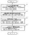
【0029】
<ステップ1A :プローブの入射光強度の測定(校正)>
このステップ1A では、生体への入射光強度を測定する。すなわち、プローブのLED2,3から生体に照射される光の強度を求める。本例では、既知の光吸収特性を持つファントム30Aを用いてこの入射光強度を求める。ファントム30Aとしては、例えば、乳白色のアクリル板が好適である。
【0030】
操作者は、まず、ファントム30AをプローブのLED2,3とフォトダイオード6の間の所定位置に配置し、本装置の入力部17の校正スイッチを操作して入射光強度の測定開始をCPU14に指示する。これによりLED2,3はそれぞれの波長の光を発生し、それらの光は上記のファントム30Aを透過してフォトダイオード6に至り、電気信号にされる。この信号は、以後、電流−電圧変換器7、アンプ8、マルチプレクサ9、フィルタ10、11、マルチプレクサ12およびA/Dコンバータ13により処理されて、CPU14に至り、ここで各波長の透過光強度Itcal1、Itcal2としてメモリ15に格納される。そしてCPU14は、測定されたItcal1、Itcal2を次式に代入して計算し、ファントム30Aに対する入射光強度Iical1、Iical2を求める。
Iical1=Itcal1×exp(Af1) (1)
Iical2=Itcal2×exp(Af2) (2)
【0031】
式中、Af1 、Af2 はファントム30Aの各波長における既知の減光度であり、予めメモリ15に格納されている。また、上記の計算結果もメモリ15に格納される。計算結果のIical1、Iical2は、メモリ15内の所定のエリアに書き込まれ、前回測定された値Iical1、Iical2があればこれらを書き替えるようにされている。そして、後述のステップ3A における計算では、最新のIical1、Iical2が用いられるようになっている。したがってこのステップ1は、入射光強度Iical を校正するステップである。
【0032】
なお、入射光強度Iical の計算は、操作者がファントム30Aにプローブを取り付け、校正スイッチを押すことによって行なうようにしたが、プローブに光または機械的センサを設け、プローブをファントム30Aに取り付けると、そのセンサが感知し、これによってCPU14は上記のような処理を開始して入射光強度Iical の計算を行なうようにしても良い。
【0033】
また、ファントム30A自体が、プローブを収納しておくホルダーにされていて、このホルダーに上記のようなセンサを設け、プローブがそのホルダーに収納されると(もちろんファントム30Aの一部はLED2,3とフォトダイオード6の間に挟持されるようになっている)、センサがその収納を感知し、これによってCPU14は入射光強度Iical の計算を行なうようにしても良い。
【0034】
LEDなどの発光素子は長期間使用すると発光強度が低下するし、プローブ表面の汚れなどによっても発光強度は変化するので、出荷時に決めたプローブの発光強度を継続して使うのは困難であり、測定の直前に入射光強度Iical を校正するのが良い。
【0035】
<ステップ2A :脈波の測定と減光度変化分比Φの計算>
次にステップ2A では、プローブを生体30に取り付け、血液の脈動による各波長の減光度変化分を測定し、それら相互の比Φを求める。
【0036】
このステップは、操作者が入力部17の測定スイッチを操作することにより開始する。このときCPU14は、A/Dコンバータ13から与えられる透過光強度It1,It2 を示す信号に基づいて、各波長の減光度A1,A2 の変化分ΔA1,ΔA2の比Φ12を求める。すなわち、次式を計算し、その結果をメモリ15に格納する。
Φ12=ΔA1/ΔA2= (AC1 /DC1)/ (AC2 /DC2) (3)
【0037】
ここで、DC1,DC2 は、脈動する透過光強度It1,It2 のうちの直流分であって、直流透過光強度と称する。また、AC1,AC2 は脈動する透過光強度It1,It2 のうちの交流分であって、交流透過光強度と称する。
【0038】
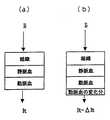
この式(3)は次のようにして得られるものである。図3(a)に示すように生体は、動脈血、静脈血、血液以外の組織、の各層からなると考えることができる。生体に入射光強度Iiの光を照射すると、透過光強度Itの光が測定される。このとき、生体による減光度A は、ランバート・ベールの法則に基づき、次式で表される。
A =log(Ii/It) =logIi −logIt (4)
【0039】
次に、図3(b)に示すように、動脈血の層の厚さが変化したとき、透過光強度は、変化分をΔItとすると、It−ΔItとなる。このとき、生体による減光度は、その変化分ΔA が加えられ、次式で表される。
A +ΔA =log{Ii/(It −ΔIt)}=logIi −log(It−ΔIt) (5)
【0040】
式(4)と式(5)からA を消去して、ΔA を求めると、ΔA は次のように入射光強度Iiを用いない式で表される。
ΔA =logIt −log(It−ΔIt) =log{It/(It −ΔIt)} (6)
この式(6)は、変形すれば、
ΔA =ΔIt/It (8)
したがって、Φ12の定義式であるΦ12=ΔA1/ΔA2と、式(8)より次式が得られる。
Φ12=ΔA1/ΔA2= (ΔIt1 /It1)/ (ΔIt2 /It2) (9)
これによれば対数計算が不要となる。この式(9)は、透過光強度がIt1,It2 を基準にしてΔIt1,ΔIt2 だけ変化した場合の式と考えられる。
【0041】
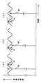
一方、図4(a)に示すように、脈動する透過光強度Itのうちピーク値を直流透過光強度DCとし、ピーク値とボトム値の差(最大の変化分)の値を交流透過光強度ACとすると、この場合、透過光強度がDCを基準にしてACだけ変化したと考えられるから、ΔIt/It=AC/DCとなり、式(9)は次のようになる。
Φ12=ΔA1/ΔA2= (AC1 /DC1)/ (AC2 /DC2) (3)
すなわち、上記の式(3)が得られる。
【0042】
なお、ここでは、透過光強度のうちピーク値を直流透過光強度DCとしたが、ACはDCに対し極めて小さいので、図4(b)に示すように、直流透過光強度DCを、脈動する透過光強度Itのボトム値としても式(3)は成り立ち、また、図4(c)に示すように、ピーク値とボトム値の平均値(ピーク値とボトム値の中間点の値)としても式(3)は成り立つ。
【0043】
このように、直流透過光強度DCは、ピーク値からボトム値の間のどこを採っても良いので、交流透過光強度の測定時点またはその周辺時点の透過光強度Itをそのまま使っても良い。
【0044】
このステップにおいて、Φ12の計算は、脈動する透過光強度It1,It2 の波の1つずつについて、すなわち心拍の一拍ずつについて行なう。
【0045】
<ステップ3A :直流減光度の計算>
次にステップ3A では、各波長の直流減光度Adc1, Adc2を求める。ここで、CPU14は、ステップ1A で求めた入射光強度Iical1、Iical2と、ステップ2A で求めた直流透過光強度DC1,DC2 を次式に代入して、各波長の直流減光度Adc1, Adc2を計算する。
Adc1= log(Iical1 /DC1)=logIical1 −logDC1 (10)
Adc2= log(Iical2 /DC2)=logIical2 −logDC2 (11)
【0046】
本装置が、発光素子(LED2,3)に流す電流を変化させない回路構成を持つ場合は、ステップ1A で求めた入射光強度Iical1、Iical2をそのまま用いる。
【0047】
しかし、本装置が、発光素子の電流を変化させて最適の透過光強度が得られるように調整する回路構成を持つ場合、ファントム30Aを用いて入射光強度測定を行なった時(校正時)の発光素子への電流値 Ccal1, Ccal2 と、生体の減光度測定を行なった時(測定時)の発光素子への電流値 Cmeas1, Cmeas2 が違うことがある。その場合CPU14は、入射光強度として、
IiA1 =Ical1 × Cmeas1 /Ccal1 (12)
IiA2 =Ical2 × Cmeas2 /Ccal2 (13)
のように、発光素子への通電電流に応じて補正した値IiA1,IiA2 を用いる。
【0048】
このステップにおいても、直流減光度Adc1, Adc2の計算は、脈動する透過光強度It1,It2 の波の1つずつについて、すなわち心拍の一拍ずつについて行なう。
【0049】
<ステップ4A :ヘモグロビン濃度の計算>
次にステップ4A では、CPU14は、ステップ2A で求めたΦ12とステップ3A で求めた直流減光度Adc1、Adc2を変数とする次式を用いてヘモグロビン濃度Hbdcを計算する。
Hbdc=a1×Φ12+b1+c1×Adc2/Adc1 (14)
【0050】
この式(14)の係数a1,b1,c1は、ある母集団(例えばある選択された10人のデータ)において式(14)を計算した結果のHbdcと、採血してシアンメトヘモグロビン法などによって測定した正確なヘモグロビン濃度Hbs の差が最小になるように最小二乗法で予め決めた値である。
【0051】
ここで、本装置の効果を示すため、ヘモグロビン濃度を、脈波の減光度変化分比Φ12だけを使って計算した場合と、本装置によってΦ12とAdc1,Adc2 を使って計算した場合とを、それぞれ採血法によって求めた場合とを比較する。
Φ12だけを使う場合、
Hbp =a2×Φ12+b2 (15)
により計算する。この場合の係数a2,b2も、上記母集団のデータにより上記と同様にして最小二乗法で予め決定されたものである。式(15)を用いて計算したヘモグロビン濃度Hbp と、採血法により測定したヘモグロビン濃度Hbs との相関を図5(a)に示す。
【0052】
これに対し、直流減光度を使い、式(14)により計算した本装置によるヘモグロビン濃度Hbdcと、採血法により測定したヘモグロビン濃度Hbs との相関を図5(b)に示す。これらの図を比較すると分かるように、計算式に直流減光度を入れることによって、採血法との一致が改善される。
【0053】
また、上記の式(14)の代わりに、次式を用いても良い。
Hbdc=a3×Φ12+b3+c3×Adc2+d3×Adc1 (16)
この式の係数a3〜d3も上記と同様にして予め決定しておく。
【0054】
ところで、直流減光度Adc1,Adc2 と直流透過光強度 DC1,DC2との間には逆相関の一定の関係があるので、直流減光度を用いて計算しなくとも、直流透過光強度をそのまま使って計算すれば同様の効果が得られる。この場合、直流透過光強度はプローブの入射光強度に比例するので、入射光強度 Iical1,Iical2を、発光素子(LED2,3)の特定の通電電流値で規格化した状態で補正する必要が有る。補正した各波長の直流透過光強度Itcomp1,Itcomp2 は次式により計算する。
Itcomp1 =DC1 ×(Iical1 /Istd1)×(Cmeas1 /Ccal1) (17)
Itcomp2 =DC2 ×(Iical2 /Istd2)×(Cmeas2 /Ccal2) (18)
DC1,DC2:測定した直流透過光強度
Iical1,Iical2:校正時に計算した入射光強度
Istd1,Istd2:標準とする入射光強度
Cmeas1,Cmeas2:生体を測定したときの発光素子の通電電流
Ccal1,Ccal2:入射光強度校正時の発光素子の通電電流
【0055】
したがって上記の式(14)、(16)の代わりに、次式を用いても良い。
Hbdc=a4×Φ12+b4+c4× Itcomp1/Itcomp2 (19)
Hbdc=a5×Φ12+b5+c5× Itcomp1+d5×Itcomp2 (20)
ここで、式(19)における係数a4〜c4、式(20)における係数a5〜d5は、それぞれ上記式(14)の係数の決定方法と同様の方法で、予め決定されるものである。
【0056】
このステップにおいても、Hbdcの計算は、脈動する透過光強度It1,It2 の波の1つづつについて、すなわち心拍の一拍づつについて行なう。そして、CPU14は、求めたHbdcをメモリ15に格納すると共に、表示部16に表示する。
【0057】
本実施の形態の装置によれば、血液以外の生体組織に光吸収がある第1波長1300nmの直流減光度または直流透過光強度と、血液に光吸収がある第2波長805nm直流減光度または直流透過光強度を用いて計算したので、測定部位における血液と血液以外の組織からなる生体組織全体の厚さが考慮され、精度良くヘモグロビン濃度を測定することができる。
なお、本実施の形態において、第1の波長を赤色光(例えば660nm)、第2の波長を赤外光(例えば940nm)とし、酸化ヘモグロビン濃度を求めることで動脈血酸素飽和度測定に適用することができる。
【0058】
[第2の実施の形態:一酸化炭素ヘモグロビン濃度測定装置]
次に、本発明の第2の実施の形態を説明する。この第2の実施の形態は、一酸化炭素ヘモグロビン濃度測定装置である。
【0059】
図6は、本実施の形態の装置の全体構成を示すブロック図である。発光部100は相異なる3つの波長の光を発生するLED20a,20b,20cとこれらを駆動する駆動回路40とから成る。
【0060】
LED20aから発生する光の波長を第1の波長とし、LED20bから発生する光の波長を第2の波長とし、LED20cから発生する光の波長を第3の波長とする。本装置において、第1の波長は940nm、第2の波長は660nm、第3の波長は620nmである。
【0061】
受光部50は、LED20a,20b,20cに対向して配置されたフォトダイオード60とこのフォトダイオード60の出力電流を電圧信号に変換する電流−電圧変換器70とアンプ80から成る。
【0062】
マルチプレクサ90は、アンプ80から与えられる信号を3個のフィルタ10a,10b,10cに振り分ける回路である。フィルタ10a,10b,10cは、各波長の透過光強度に対応する信号のノイズを除去する回路であり、これらの出力信号は、マルチプレクサ120でそれぞれの出力のタイミングを制御されA/Dコンバータ130に至るようにされている。A/Dコンバータ130はマルチプレクサ120から与えられる信号をデジタル信号に変換する回路である。
【0063】
CPU140は駆動回路40、マルチプレクサ90およびマルチプレクサ120に制御信号を出力してそれらを制御すると共に、A/Dコンバータ130から与えられる信号に基づいて演算を行なう回路である。
【0064】
メモリ150は、CPU140が行なう処理のためのプログラムを格納されており、またCPU140から与えられるデータを格納するものである。
【0065】
表示部160はCPU140から与えられるデータを表示するものであり、入力部170は複数のスイッチ(後述する校正スイッチおよび測定スイッチを含む)、複数のキーを備え、操作者の操作に応じた信号をCPU140に出力するものである。本装置のプローブは、LED20a,20b,20cとフォトダイオード60を備え、これらのLED20a,20b,20cとフォトダイオード60の間で生体30を挟持するようになっている。
次に、本装置の動作を図7を参照して説明する。
【0066】
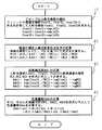
<ステップ1B :プローブの入射光強度の測定>
このステップ1B では、生体30への入射光強度を測定する。ここではプローブの3個のLED20a,20b,20cからそれぞれ生体30に照射される光の強度、すなわち生体30への入射光強度を求める。上記の第1の実施の形態の装置におけるステップ1A と同様にして、操作者は、減光度が既知のファントム30AをプローブのLED20a,20b,20cとフォトダイオード60との間の所定位置に配置し、次に校正スイッチを操作して入射光強度測定開始をCPU140に指示する。これによりCPU140は、ファントム30Aを透過した各波長の光強度Itcal1,Itcal2,Itcal3から次式を計算して、3波長の入射光強度Iical1、Iical2、Iical3を求め、これらをメモリ150に格納する。
Iical1=Itcal1×exp(Af1)
Iical2=Itcal2×exp(Af2)
Iical3=Itcal2×exp(Af3)
ここで、Af1,Af2,Af3 はファントム30Aの各波長の既知の減光度であり、予めメモリ150に格納されている。
【0067】
<ステップ2B :脈波の測定と減光度比Φの計算>
次にステップ2B では、操作者は、プローブを生体30に取り付け、測定スイッチを操作する。これによりCPU140は、生体30の血液の脈動による各波長の減光度変化分を測定し、それらの相互の比Φを求める。
【0068】
すなわちこのステップでは、CPU140は上記第1の実施の形態におけるステップ2A と同様にして各波長の直流透過光強度と交流透過光強度を求め、これらを用いて各波長の減光度の変化分の相互の比を求めるのであるが、ここでは、3波長の光を用いるので、次の式を計算してΦ12、Φ13を求め、その結果をメモリ150に格納する。
Φ12=ΔA1/ΔA2= (AC1 /DC1)/ (AC2 /DC2) (21)
Φ13=ΔA1/ΔA3= (AC1 /DC1)/ (AC3 /DC3) (22)
Φ12:第1波長と第2波長の減光度A1,A2 の変化分ΔA1, ΔA2の相互比
Φ13:第1波長と第3波長の減光度A1,A3 の変化分ΔA1, ΔA3の相互比
DC1,DC2,DC3:第1〜3波長の透過光強度It1,It2,It3 における直流透過光強度
AC1,AC2,AC3:第1〜3波長の透過光強度It1,It2,It3 における交流透過光強度
【0069】
このステップにおいて、Φ12、Φ13の計算は、脈動する透過光強度It1,It2,Ii3 の波の1つずつについて、すなわち心拍の一拍ずつについて行なう。
【0070】
<ステップ3B :直流減光度の計算>
次にステップ3B では、各波長の直流減光度Adc1,Adc2,Adc3を求める。ここで、CPU140は、ステップ1B で求めた入射光強度Iical1,Iical2,Iical3と、ステップ2B で求めた直流透過光強度DC1,DC2,DC3 を次式に代入して、各波長の直流減光度Adc1, Adc2を求め、その結果をメモリ150に格納する。
Adc1= log(Iical1 /DC1)=logIical1 −logDC1 (23)
Adc2= log(Iical2 /DC2)=logIical2 −logDC2 (24)
Adc3= log(Iical3 /DC3)=logIical3 −logDC3 (25)
【0071】
本装置が、発光素子(LED20a,20b,20c)に流す電流を変化させない回路構成を持つ場合は、上記のようにステップ1B で求めた入射光強度Iical1,Iical2,Iical3をそのまま用いる。
【0072】
しかし、本装置が、発光素子の電流を変化させて最適の透過光強度が得られるように調整する回路構成を持つ場合、ファントム30Aを用いて入射光強度測定を行なった時(校正時)の発光素子への電流値 Ccal1, Ccal2 ,Ccal3と生体の減光度測定を行なった時(測定時)の発光素子への電流値 Cmeas1, Cmeas2, Cmeas3 が違うことがある。その場合入射光強度IiA1,IiA2 は、
IiA1 =Ical1 × Cmeas1 /Ccal1 (26)
IiA2 =Ical2 × Cmeas2 /Ccal2 (27)
IiA3 =Ical3 × Cmeas3 /Ccal3 (28)
のように、発光素子への通電電流に応じて補正した値を用いる。
【0073】
このステップにおいても、直流減光度Adc1,Adc2,Adc3の計算は、脈動する透過光強度It1,It2,It3 の波の1つずつについて、すなわち心拍の一拍ずつについて行なう。
【0074】
<ステップ4B :一酸化炭素ヘモグロビン濃度の計算>
次にステップ4B では、CPU140は、ステップ2B で求めたΦ12、Φ13とステップ3B で求めた直流減光度Adc1、Adc2、Adc3を変数とする次式を用いて一酸化炭素ヘモグロビン濃度COHbdcを計算する。
この式(29)の係数a6〜e6はある母集団(例えばある選択された10人のデータ)において、式(29)を計算した結果のCOHbdcと、採血して測定した正確な一酸化炭素ヘモグロビン値COHbs の差が最小になるように最小二乗法で予め決めた値である。
【0076】
ここで、本装置の効果を示すため、一酸化炭素ヘモグロビン濃度を、脈波の減光度変化分比Φ12、Φ13だけを使って計算した場合と、本装置により、Φ12、Φ13と直流減光度Adc1,Adc2,Adc3を使って計算した場合とを、それぞれ採血法によって求めた場合とを比較する。
【0077】
Φ12、Φ13だけを使う場合、
COHbp =a7×Φ12+b7×Φ13+c7 (30)
により計算する。この場合の係数a7,b7,c7も、上記母集団のデータを用いて上記と同様にして予め決定されたものである。式(30)を用いて計算した一酸化炭素ヘモグロビン濃度COHbp と、採血法により測定した一酸化炭素ヘモグロビン濃度COHbs との相関を図8(a)に示す。
【0078】
これに対し、直流減光度を使い、式(29)により計算した本装置による一酸化炭素ヘモグロビン濃度C0Hbdcと、採血法により測定したCOHbs との相関を図8(b)に示す。
【0079】
これらの図を比較すると分かるように、計算式に直流減光度を入れることによって、採血法との一致が改善される。
【0080】
また、上記の式(29)の代わりに、次式を用いても良い。
【0081】
ところで、直流減光度Adc1,Adc2,Adc3と直流透過光強度 DC1,DC2,DC3との間には逆相関の一定の関係があるので、減光度で計算しなくても、直流透過光強度をそのまま使って計算すれば同様の効果が得られる。この場合、直流透過光強度はプローブの入射光強度に比例するので、入射光強度を、発光素子(LED20a,20b,20c)の特定の通電電流値で規格化した状態で補正する必要が有る。補正した各波長の直流透過光強度Itcomp1,Itcomp2,Itcomp3 は次式により計算する。
Itcomp1 =DC1 ×(Iical1 /Istd1)×(Cmeas1 /Ccal1) (32)
Itcomp2 =DC2 ×(Iical2 /Istd2)×(Cmeas2 /Ccal2) (33)
Itcomp3 =DC3 ×(Iical3 /Istd3)×(Cmeas3 /Ccal3) (34)
DC1,DC2,DC3:測定した透過光強度
Iical1,Iical2,Iical3: 校正時に計算した入射光強度
Istd1,Istd2,Istd3:標準とする入射光強度
Cmeas1,Cmeas2,Cmeas3: 生体を測定したときの発光素子の通電電流
Ccal1,Ccal2,Ccal3:入射光強度校正時の発光素子の通電電流
【0082】
したがって、上記の式(29)、(31)の代わりに、次式を用いても良い。
COHbdc=a9×Φ12+b9×Φ13+c9+d9×Itcomp1 /Itcomp2 +e9×Itcomp1 /Itcomp3 (35)
COHbdc=a10 ×Φ12+b10 ×Φ13+ c10+ d8 ×Itcomp1 +e10 ×Itcomp2 +f10 ×Itcomp3 (36)
式(35)における係数a9〜e9、式(36)における係数a10 〜f10 は、それぞれ上記と同様の母集団のデータを用いて、上記と同様にして予め決定されるものである。
【0083】
このステップにおいても、COHbdcの計算は、脈動する透過光強度It1,It2,It3 の波の1つずつについて、すなわち心拍の一拍ずつについて行なう。そして、CPU140は、求めたCOHbdcをメモリ150に格納すると共に、表示部160に表示する。
【0084】
本実施の形態の装置によれば、血液に光吸収がある第1波長940nm、第2波長660nmおよび第3波長620nmの直流減光度または直流透過光強度を用いて計算したので、測定部位の血液層全体の厚さが考慮され、精度良くヘモグロビン濃度を測定することができる。
【0085】
[第3の実施の形態:色素濃度測定装置]
次に、本発明の第3の実施の形態を説明する。この第3の実施の形態は、色素濃度測定装置である。この装置は、第2の実施の形態と同様に3波長の光を用いるので、装置の構成ブロック図は図6と同じである。このため、本装置の構成ブロック図は省略し、以下の説明では図6を利用する。しかし、CPU140が行なう処理のプログラムは、図9に示すように第2の実施の形態と異なる。また、第1の波長は940nm、第2の波長は660nm、第3の波長は805nmである。以下、図9を参照して本装置の動作を説明する。
【0086】
<ステップ1C :プローブの入射光強度の測定(校正)>
このステップ1C では、生体30への入射光強度を測定する。上記の第2の実施の形態の装置におけるステップ1B と同様にして、ファントム30Aを用い、3波長の入射光強度Iical1、Iical2、Iical3を求め、これらをメモリ150に格納する。
【0087】
<ステップ2C :脈波の測定と減光度変化分比Φの計算>
次にステップ2C では、操作者は、プローブを生体30に装着した後、色素を注入する。色素として例えばインドシアニングリーンを用いる。そして、上記第2の実施の形態におけるステップ2B と同様にして各波長の減光度の変化分の相互の比を求める。すなわち、次の式を計算してΦ12、Φ13を求め、その結果をメモリ150に格納する。
Φ12=ΔA1/ΔA2= (AC1 /DC1)/ (AC2 /DC2) (21)
Φ13=ΔA1/ΔA3= (AC1 /DC1)/ (AC3 /DC3) (22)
Φ12:第1波長と第2波長の減光度A1,A2 の変化分ΔA1, ΔA2の相互比
Φ13:第1波長と第3波長の減光度A1,A3 の変化分ΔA1, ΔA3の相互比
DC1,DC2,DC3:第1〜3波長の透過光強度It1,It2,It3 における直流透過光強度
AC1,AC2,AC3:第1〜3波長の透過光強度It1,It2,It3 における交流透過光強度
【0088】
このステップにおいて、Φ12、Φ13の計算は、脈動する透過光強度It1,It2,Ii3 の波の1つずつについて、すなわち心拍の一拍ずつについて行なう。
【0089】
<ステップ3C :直流減光度の計算>
次にステップ3C では、各波長の直流減光度Adc1,Adc2,Adc3を求める。ここで、CPU140は、第2の実施の形態のステップ3B と同様にして、各波長の入射光強度Iical1,Iical2,Iical3と、各波長の直流透過光強度DC1,DC2,DC3 と次式により、各波長の直流減光度Adc1, Adc2を求め、その結果をメモリ150に格納する。
Adc1= log(Iical1 /DC1)=logIical1 −logDC1 (23)
Adc2= log(Iical2 /DC2)=logIical2 −logDC2 (24)
Adc3= log(Iical3 /DC3)=logIical3 −logDC3 (25)
【0090】
本装置が、発光素子(LED20a,20b,20c)に流す電流を変化させない回路構成を持つ場合、上記のようにステップ1C で求めた入射光強度Iical1,Iical2,Iical3をそのまま用いる。
【0091】
しかし、本装置が、発光素子の電流を変化させて最適の透過光強度が得られるように調整する回路構成を持つ場合、ファントム30Aを用いて入射光強度測定を行なった時(校正時)の発光素子への電流値 Ccal1, Ccal2 ,Ccal3と生体の減光度測定を行なった時(測定時)の発光素子への電流値 Cmeas1, Cmeas2, Cmeas3 が違うことがある。その場合入射光強度IiA1,IiA2 は、
IiA1 =Ical1 × Cmeas1 /Ccal1 (26)
IiA2 =Ical2 × Cmeas2 /Ccal2 (27)
IiA3 =Ical3 × Cmeas3 /Ccal3 (28)
のように、発光素子への通電電流に応じて補正した値を用いる。
【0092】
このステップにおいても、直流減光度Adc1,Adc2,Adc3の計算は、脈動する透過光強度It1,It2,It3 の波の1つずつについて、すなわち心拍の一拍ずつについて行なう。
【0093】
<ステップ4C :色素濃度の計算>
次にステップ4C では、CPU140は、上記ステップ2C で求めたΦ12、Φ13と上記ステップ3C で求めた直流減光度Adc1、Adc2、Adc3を変数とする次式を用いて色素濃度Cdを計算する。
この式(37)の係数a11 〜e11 はある母集団(例えばある選択された10人のデータ)において、式(37)を計算した結果であるCddcと、採血して測定した正確なCds 値の差が最小になるように最小二乗法で予め決めた値である。
ここで、本装置の効果を示すため、色素濃度を、脈波の減光度変化分比Φ12、Φ13だけを使って計算した場合と、本装置によるΦ12、Φ13とAdc1,Adc2,Adc3を使って計算した場合とを、それぞれ採血法によって求めた場合とを比較する。
【0095】
Φ12、Φ13だけを使う場合、
Cdp =a12 ×Φ12+b12 ×Φ13+c12 (38)
により計算する。この場合の係数a12,b12,c12 も、上記母集団のデータを用いて上記と同様にして予め決定されたものである。式(38)を用いて計算した色素濃度Cdp と、採血法により測定した色素濃度Cds との相関を図10(a)に示す。これに対し、直流減光度を使い、式(37)により計算した本装置による色素濃度Cddcと、採血法により測定した色素濃度Cds との相関を図10(b)に示す。
【0096】
これらの図を比較すると分かるように、計算式に直流減光度を入れることによって、採血法との一致が改善される。
また、上記の式(37)の代わりに、次式を用いても良い。
【0097】
ところで、直流減光度Adc1,Adc2,Adc3と直流透過光強度 DC1,DC2,DC3との間には逆相関の一定の関係があるので、減光度で計算しなくても、直流透過光強度をそのまま使っても同様の効果が得られる。この場合、直流透過光強度はプローブの入射光強度に比例するので、入射光強度を、発光素子(LED20a,20b,20c)の特定の通電電流値で規格化した状態で補正する必要が有る。補正した各波長の直流透過光強度Itcompは次式により計算する。
Itcomp1 =DC1 ×(Iical1 /Istd1)×(Cmeas1 /Ccal1) (40)
Itcomp2 =DC2 ×(Iical2 /Istd2)×(Cmeas2 /Ccal2) (41)
Itcomp3 =DC3 ×(Iical3 /Istd3)×(Cmeas3 /Ccal3) (42)
DC1,DC2,DC3:測定した透過光強度
Iical1,Iical2,Iical3: 校正時に計算した入射光強度
Istd1,Istd2,Istd3:標準とする入射光強度
Cmeas1,Cmeas2,Cmeas3: 生体を測定したときの発光素子の通電電流
Ccal1,Ccal2,Ccal3:入射光強度校正時の発光素子の通電電流
【0098】
したがって、上記の式(37)、(39)の代わりに、次式を用いても良い。
ここで、式(43)における係数a14 〜e14 、式(44)における係数a15 〜f15 は、それぞれ上記と同様の母集団のデータを用いて、上記と同様にして予め決定されるものである。
【0100】
このステップにおいても、Cddcの計算は、脈動する透過光強度It1,It2,It3 の波の1つずつについて、すなわち心拍の一拍ずつについて行なう。そして、CPU140は、求めたCddcをメモリ150に格納すると共に、表示部160に表示する。
【0101】
本実施の形態の装置によれば、血液に光吸収がある第1波長940nm、第2波長805nmおよび第3波長660nmの直流減光度または直流透過光強度を用いて計算したので、測定部位の血液層全体の厚さが考慮され、精度良く色素濃度を測定することができる。
【0102】
なお、以上の説明においては、発光素子に流れる電流を制御して生体に照射する光強度を変える場合について説明したが、これは、発光素子に印加する電圧を制御して発光素子の光強度を変え、測定される入射光強度や直流透過光強度をその電圧値に応じて補正するようにしても良い。
【0103】
【発明の効果】
本発明によれば、パルスフォトメトリーを原理とする血中吸光物質濃度測定において、精度良く測定することができる。
【図面の簡単な説明】
【図1】第1の実施の形態のヘモグロビン濃度測定装置の動作を説明するための図。
【図2】第1の実施の形態のヘモグロビン濃度測定装置のブロック構成図。
【図3】生体へ光を照射したときの入射光強度と透過光強度との関係を説明する図。
【図4】直流透過光強度を説明する図。
【図5】第1の実施の形態のヘモグロビン濃度測定装置の効果を説明する図。
【図6】第2の実施の形態の一酸化炭素ヘモグロビン濃度測定装置のブロック構成図。
【図7】第2の実施の形態の一酸化炭素ヘモグロビン濃度測定装置の動作を説明するための図。
【図8】第2の実施の形態の一酸化炭素ヘモグロビン濃度測定装置の効果を説明する図。
【図9】第3の実施の形態の色素濃度測定装置の動作を説明するための図。
【図10】第3の実施の形態の色素濃度測定装置の効果を説明する図。
【符号の説明】
1、100 発光部
5、50 受光部
14、140 CPU[0001]
TECHNICAL FIELD OF THE INVENTION
The present invention relates to an improvement in a blood light absorbing substance concentration measuring device based on pulse photometry, such as a pulse oximeter or a pulse type dye dilution curve measuring device.
[0002]
[Prior art]
Pulse photometry is not limited to a pulse oximeter, and at present, a dye called indocyanine green (ICG) is administered to the blood as a pulsed dye dilution method, and the blood concentration is measured. Devices for measuring cardiac output, circulating blood volume, plasma elimination rate of ICG, and clearance have also been put into practical use (for example, see Non-Patent
[0003]
For example, when measuring the concentration of a substance in blood using light of two wavelengths, conventionally, the ratio Φ12 of the dimming degree change between two wavelengths generated by the pulsation of blood is obtained, and Φ12 and the substance concentration are determined. The substance concentration was calculated and found based on the fact that there was a certain relationship between the two (for example, see Patent Document 3). That is,
C = F (Φ12)
C: blood concentration of the substance
F: Function indicating a certain relationship
Is represented by In general, when light of n kinds of wavelengths is used, the ratio Φ of the change in the dimming degree of each wavelength is n-1 at the maximum. For example, in the case of three wavelengths, the ratio Φ12 of the dimming degree change between the first wavelength and the second wavelength and the ratio Φ13 of the dimming degree change between the first wavelength and the third wavelength are used.
C = F (Φ12, Φ13)
It becomes.
In the case of a pulse oximeter, the
[0004]
However, according to such a measurement method, although there is an approximately constant relationship between the extinction ratio change ratio and the substance concentration, there is an individual difference in this relationship, and even in the same individual, the measurement time and It varies depending on the measurement site and causes measurement errors. For example, in the pulse oximeter, when the finger on which the probe is attached is changed or the hand is raised and lowered, the calculated value changes by about 1% even if the actual arterial oxygen saturation SpO2 is constant. The main causes of this measurement error are as follows.
(1) Since blood is a light-scattering substance, the degree of dimming caused by scattering varies depending on the thickness of blood.
(2) There are light passing through blood and light not passing through blood.
[0005]
[Patent Document 1]
Japanese Patent Publication No. 3-77135
[Patent Document 2]
JP-A-2002-228579
[Patent Document 3]
JP-B-53-26437
[Patent Document 4]
Japanese Patent No. 2608828
[Non-patent document 1]
Takehiko Iijima, et al. Cardiac output and circulating blood volume analysis by pulse dye-densitometry. J Clin Monitor 1997; 13: 81-89.
[Non-patent document 2]
Takasuke Imai, et al. Measurement of cardic output by pulse dye-densitometry using indocyanine green. Anestheology 1997; 87: 816-822.
[Non-Patent Document 3]
Takasuke Imai, et al. Measurement of blood concentration of indocyanine green by pulse dye-densitometry-Comparison with the conventionalspectrophotometric. J Clin Monitor 1998; 14: 477-484.
[0006]
[Problems to be solved by the invention]
As described above, when obtaining the blood light absorbing
The present invention has been made in view of such conventional drawbacks, and an object of the present invention is to accurately measure the concentration of a light-absorbing substance in blood in measurement by pulse photometry.
[0007]
[Means for Solving the Problems]
In the present invention, when calculating the
C = F (Φ, Adc)
Here, when measuring with light of n wavelengths, Φ is used at most n−1 and Adc is used at maximum n. For example, when measuring at three wavelengths, the
C = F (Φ12, Φ13, Adc1, Adc2, Adc3)
The DC extinction degree Adc is expressed as follows using the incident light intensity Ii and the transmitted light intensity It.
Adc = log (Ii / It) = logIi−logIt
Here, It is the transmitted light intensity of the light transmitted through the living body and can be measured continuously, but the incident light intensity Ii needs to be measured and known in advance. As a method of knowing Ii, there is a method described in
[0008]
At wavelengths such as 660 nm, 805 nm, and 940 nm, hemoglobin has light absorption, but there is almost no light absorption by water. Mainly related to blood volume. At 1300 nm, where the light absorption of hemoglobin is small and the light absorption of water is large, the DC attenuation is mainly related to the thickness (water content) of the living tissue. Therefore, by measuring the DC attenuation at these wavelengths and incorporating them as variables in the calculation formula, the errors due to the above-mentioned error factors (1) and (2) are corrected, and the measurement accuracy of the concentration of the light absorbing substance in blood is improved. Can be improved.
[0009]
Further, in the present invention, since the direct current dimming degree and the direct current transmitted light intensity (the direct current component of the transmitted light intensity) have a fixed relationship, the
C = F1 (Φ, DC)
Here, when measuring with light of n wavelengths, Φ is used at most n−1 and DC is used at most n. For example, when measuring at three wavelengths, the
C = F1 (Φ12, Φ13, DC1, DC2, DC3)
As described above, even when a function using the dimming degree change ratio Φ and the DC transmitted light intensity DC as variables is used, the measurement accuracy of the concentration of the light-absorbing substance in blood can be similarly improved.
[0010]
Therefore, the invention according to
[0011]
According to a second aspect of the present invention, in the blood-absorbing substance concentration measuring apparatus according to the first aspect, the second arithmetic means includes, for each wavelength, the incident light intensity measured by the incident light intensity measuring means. Calculating and calculating a direct current dimming degree of the living tissue based on the transmitted light intensity measured by the transmitted light intensity measuring means, and blood based on the direct current dimming degree and the ratio determined by the first calculating means. It is characterized in that it is obtained by calculating the concentration of the light absorbing substance therein.
[0012]
According to a third aspect of the present invention, in the blood-absorbing substance concentration measuring apparatus according to the second aspect, the second calculating means obtains a mutual ratio of DC extinction degrees of respective wavelengths, and obtains the ratio and the ratio. The method is characterized in that the concentration of the light-absorbing substance in blood is calculated based on the ratio calculated by the first calculating means.
[0013]
According to a fourth aspect of the present invention, in the blood-absorbing substance concentration measuring apparatus according to the first aspect, the second arithmetic means includes, for each wavelength, an incident light intensity measured by the incident light intensity measuring means. Calculating the DC transmitted light intensity of the living tissue based on the transmitted light intensity measured by the transmitted light intensity measuring means, and calculating the DC transmitted light intensity based on the ratio obtained by the first calculating means. And calculating the concentration of the light-absorbing substance in the blood.
[0014]
According to a fifth aspect of the present invention, in the blood-absorbing substance concentration measuring apparatus according to the fourth aspect, the second calculating means obtains a mutual ratio of the DC transmitted light intensities of the respective wavelengths, The method is characterized in that the concentration of the light-absorbing substance in the blood is calculated based on the ratio calculated by the first calculating means.
[0015]
According to a sixth aspect of the present invention, in the blood-absorbing substance concentration measuring apparatus according to any one of the first to fifth aspects, the light irradiating means is configured such that the light source includes a light emitting element, and the light source is supplied to the light emitting element. A control unit for controlling a current or a voltage to be applied, wherein the second calculating means corrects the measured incident light intensity according to the current or the voltage controlled by the control unit, and corrects the corrected incident light intensity. The calculation is performed using
[0016]
According to a seventh aspect of the present invention, in the blood-absorbing substance concentration measuring apparatus according to any one of the first to sixth aspects, the incident light intensity measuring means includes the light irradiating means and the transmitted light intensity measuring means. In the case where a phantom with a known dimming degree is arranged at a predetermined position in between, the incident light intensity is calculated and obtained based on the transmitted light intensity of each wavelength measured by the transmitted light intensity measuring means. Features.
[0017]
The invention according to
[0018]
According to a ninth aspect of the present invention, there is provided a light source for emitting light of n kinds of wavelengths, a light irradiating means for irradiating the living tissue with these lights, and light of n kinds of wavelengths emitted from this light irradiating means. Incident light intensity measuring means for measuring the incident light intensity to the living tissue, and transmitted light intensity measuring means for receiving light of n wavelengths transmitted through the living tissue and measuring the transmitted light intensity thereof; A first calculation for calculating, based on the transmitted light intensity measured by the transmitted light intensity measuring means, at most n-1 ratios among mutual ratios of the dimming degree changes of the respective wavelengths generated due to the blood thickness change. Means, at most n-1 ratios obtained by the first calculating means, the incident light intensity obtained by the incident light intensity measuring means, and the transmitted light intensity obtained by the transmitted light intensity measuring means. On the basis of the above, at most n DC attenuations corresponding to each wavelength are calculated and obtained, ; And a second computing means for obtaining by calculating the absorbance substance concentration in the blood based on these calculation results.
[0019]
Further, the invention according to
[0020]
According to an eleventh aspect of the present invention, in the blood-absorbing substance concentration measuring device according to any one of the first to eleventh aspects, the light source is light having a wavelength at which blood absorbs light and / or light other than blood. It is characterized by emitting light having a wavelength at which light is absorbed by living tissue.
[0021]
BEST MODE FOR CARRYING OUT THE INVENTION
[First Embodiment: Hemoglobin concentration measuring device]
Next, a first embodiment of the present invention will be described. The first embodiment is a hemoglobin concentration measuring device.
[0022]
FIG. 2 is a block diagram showing the overall configuration of the apparatus according to the present embodiment. The
[0023]
The
[0024]
The
[0025]
The
[0026]
The
[0027]
The
[0028]
The probe of the device mounted on the living body includes the
Next, the operation of the present apparatus will be described with reference to FIG.
[0029]
<Step 1A: Measurement (Calibration) of Probe Incident Light Intensity>
In Step 1A, the intensity of light incident on the living body is measured. That is, the intensity of light emitted to the living body from the
[0030]
First, the operator arranges the
Iical1 = Itcal1 × exp (Af1) (1)
Iical2 = Itcal2 × exp (Af2) (2)
[0031]
In the formula, Af1 and Af2 are known dimming degrees at each wavelength of the
[0032]
The calculation of the incident light intensity Iical was performed by the operator attaching the probe to the
[0033]
Further, the
[0034]
When a light emitting element such as an LED is used for a long period of time, the light emission intensity decreases, and the light emission intensity changes due to dirt on the probe surface, so it is difficult to continuously use the light emission intensity of the probe determined at the time of shipment. It is better to calibrate the incident light intensity Iical immediately before the measurement.
[0035]
<
Next, in
[0036]
This step is started when the operator operates the measurement switch of the
Φ12 = ΔA1 / ΔA2 = (AC1 / DC1) / (AC2 / DC2) (3)
[0037]
Here, DC1 and DC2 are DC components of the pulsating transmitted light intensity It1 and It2, and are referred to as DC transmitted light intensity. AC1 and AC2 are AC components of the pulsating transmitted light intensity It1 and It2, and are referred to as AC transmitted light intensity.
[0038]
This equation (3) is obtained as follows. As shown in FIG. 3A, the living body can be considered to be composed of layers of arterial blood, venous blood, and tissues other than blood. When the living body is irradiated with light having the incident light intensity Ii, the light having the transmitted light intensity It is measured. At this time, the dimming degree A by the living body is expressed by the following equation based on Lambert-Beer's law.
A = log (Ii / It) = logIi−logIt (4)
[0039]
Next, as shown in FIG. 3B, when the thickness of the arterial blood layer changes, the transmitted light intensity becomes It−ΔIt, where ΔIt is the change. At this time, the dimming degree due to the living body is represented by the following equation with the change ΔA added thereto.
A + ΔA = log {Ii / (It−ΔIt)} = logIi−log (It−ΔIt) (5)
[0040]
When A 1 is eliminated from Equations (4) and (5) and ΔA is obtained, ΔA is expressed by an equation not using the incident light intensity Ii as follows.
ΔA = logIt−log (It−ΔIt) = log {It / (It−ΔIt)} (6)
This equation (6) can be transformed into
ΔA = ΔIt / It (8)
Therefore, the following expression is obtained from Φ12 = ΔA1 / ΔA2, which is the definition expression of Φ12, and Expression (8).
Φ12 = ΔA1 / ΔA2 = (ΔIt1 / It1) / (ΔIt2 / It2) (9)
This eliminates the need for logarithmic calculations. Equation (9) is considered to be an equation when the transmitted light intensity changes by ΔIt1, ΔIt2 with respect to It1, It2.
[0041]
On the other hand, as shown in FIG. 4A, the peak value of the pulsating transmitted light intensity It is defined as the DC transmitted light intensity DC, and the difference between the peak value and the bottom value (the maximum change) is the AC transmitted light intensity. If AC is assumed, in this case, it is considered that the transmitted light intensity has changed only by AC with respect to DC, so that ΔIt / It = AC / DC, and Expression (9) becomes as follows.
Φ12 = ΔA1 / ΔA2 = (AC1 / DC1) / (AC2 / DC2) (3)
That is, the above equation (3) is obtained.
[0042]
Here, the peak value of the transmitted light intensity is set to the DC transmitted light intensity DC. However, since the AC is extremely smaller than the DC, the DC transmitted light intensity DC pulsates as shown in FIG. Equation (3) holds true for the bottom value of the transmitted light intensity It, and as shown in FIG. 4C, the average value of the peak value and the bottom value (the value at the midpoint between the peak value and the bottom value). Equation (3) holds.
[0043]
As described above, since the DC transmitted light intensity DC may take any value between the peak value and the bottom value, the transmitted light intensity It at the time of measuring the AC transmitted light intensity or at a time around the same may be used as it is.
[0044]
In this step, the calculation of Φ12 is performed for each pulsating wave of the transmitted light intensity It1, It2, that is, for each beat of the heartbeat.
[0045]
<Step 3A: Calculation of DC attenuation>
Next, in step 3A, DC attenuations Adc1 and Adc2 of respective wavelengths are obtained. Here, the
Adc1 = log (Iical1 / DC1) = logIical1−logDC1 (10)
Adc2 = log (Iical2 / DC2) = logIical2-logDC2 (11)
[0046]
When the present device has a circuit configuration that does not change the current flowing through the light emitting elements (
[0047]
However, when the present device has a circuit configuration for adjusting the current of the light-emitting element to obtain the optimum transmitted light intensity, the measurement is performed when the incident light intensity measurement is performed using the
IiA1 = Ical1 × Cmeas1 / Ccal1 (12)
IiA2 = Ical2 × Cmeas2 / Ccal2 (13)
As described above, the values IiA1 and IiA2 corrected according to the current supplied to the light emitting element are used.
[0048]
Also in this step, the calculation of the DC extinction degrees Adc1 and Adc2 is performed for each of the pulsating waves of the transmitted light intensities It1 and It2, that is, for each beat of the heartbeat.
[0049]
<Step 4A: Calculation of hemoglobin concentration>
Next, in step 4A, the
Hbdc = a1 × Φ12 + b1 + c1 × Adc2 / Adc1 (14)
[0050]
The coefficients a1, b1, and c1 in the equation (14) are calculated by using Hbdc obtained by calculating the equation (14) in a certain population (for example, data of a selected 10 persons), and by collecting blood to obtain a cyanmethemoglobin method or the like. This is a value determined in advance by the least squares method so that the difference between the measured accurate hemoglobin concentrations Hbs is minimized.
[0051]
Here, in order to show the effect of the present apparatus, the case where the hemoglobin concentration was calculated using only the pulse wave extinction degree change ratio Φ12 and the case where the hemoglobin concentration was calculated using the present apparatus using Φ12 and Adc1 and Adc2 were: The results are compared with those obtained by the blood sampling method.
When using only Φ12,
Hbp = a2 × Φ12 + b2 (15)
Is calculated by In this case, the coefficients a2 and b2 are also determined in advance by the least squares method in the same manner as described above based on the data of the population. FIG. 5A shows the correlation between the hemoglobin concentration Hbp calculated using the equation (15) and the hemoglobin concentration Hbs measured by the blood collection method.
[0052]
On the other hand, FIG. 5B shows the correlation between the hemoglobin concentration Hbdc calculated by the present apparatus using the DC extinction degree and calculated by the equation (14) and the hemoglobin concentration Hbs measured by the blood sampling method. As can be seen by comparing these figures, by including the DC attenuation in the calculation formula, the consistency with the blood sampling method is improved.
[0053]
Further, instead of the above equation (14), the following equation may be used.
Hbdc = a3 × Φ12 + b3 + c3 × Adc2 + d3 × Adc1 (16)
The coefficients a3 to d3 of this equation are also determined in the same manner as described above.
[0054]
By the way, since there is a constant inverse correlation between the DC attenuation Adc1 and Adc2 and the DC transmitted light intensity DC1 and DC2, the DC transmitted light intensity can be used as it is without using the DC attenuation. A similar effect can be obtained by calculation. In this case, since the DC transmitted light intensity is proportional to the incident light intensity of the probe, it is necessary to correct the incident light intensity Iical1 and Iical2 in a state where the intensity is standardized by a specific energizing current value of the light emitting elements (
Itcomp1 = DC1 × (Ical1 / 1 / Std1) × (Cmeas1 / Ccal1) (17)
Itcomp2 = DC2 × (Iical2 / Istd2) × (Cmeas2 / Ccal2) (18)
DC1, DC2: DC transmitted light intensity measured
Iical1, Iical2: Incident light intensity calculated at the time of calibration
Istd1, Istd2: standard incident light intensity
Cmeas1, Cmeas2: current flowing through the light emitting element when measuring a living body
Ccal1, Ccal2: energizing current of the light emitting element at the time of incident light intensity calibration
[0055]
Therefore, the following equation may be used instead of the above equations (14) and (16).
Hbdc = a4 × Φ12 + b4 + c4 × Itcomp1 / Itcomp2 (19)
Hbdc = a5 × Φ12 + b5 + c5 × Itcomp1 + d5 × Itcomp2 (20)
Here, the coefficients a4 to c4 in the equation (19) and the coefficients a5 to d5 in the equation (20) are determined in advance by the same method as the method of determining the coefficient in the equation (14).
[0056]
Also in this step, the calculation of Hbdc is performed for each pulsating wave of the transmitted light intensity It1, It2, that is, for each beat of the heartbeat. Then, the
[0057]
According to the apparatus of the present embodiment, the DC attenuation or the DC transmitted light intensity at the first wavelength of 1300 nm, which has light absorption in living tissue other than blood, and the DC attenuation or the DC intensity of the second wavelength of 805 nm, which has light absorption in blood. Since the calculation is performed using the transmitted light intensity, the hemoglobin concentration can be measured accurately with consideration given to the thickness of the whole living tissue including blood and tissues other than blood at the measurement site.
In the present embodiment, the first wavelength is set to red light (for example, 660 nm), the second wavelength is set to infrared light (for example, 940 nm), and the oxygenated hemoglobin concentration is obtained to be applied to arterial blood oxygen saturation measurement. Can be.
[0058]
[Second embodiment: carboxyhemoglobin concentration measuring device]
Next, a second embodiment of the present invention will be described. This second embodiment is a carboxyhemoglobin concentration measuring device.
[0059]
FIG. 6 is a block diagram showing the overall configuration of the apparatus according to the present embodiment. The light emitting unit 100 includes
[0060]
The wavelength of the light generated from the
[0061]
The light receiving unit 50 includes a
[0062]
The
[0063]
The
[0064]
The
[0065]
The
Next, the operation of the present apparatus will be described with reference to FIG.
[0066]
<
In
Iical1 = Itcal1 × exp (Af1)
Iical2 = Itcal2 × exp (Af2)
Iical3 = Itcal2 × exp (Af3)
Here, Af1, Af2, and Af3 are known dimming degrees of each wavelength of the
[0067]
<Step 2B: Measurement of pulse wave and calculation of extinction ratio Φ>
Next, in step 2B, the operator attaches the probe to the living
[0068]
That is, in this step, the
Φ12 = ΔA1 / ΔA2 = (AC1 / DC1) / (AC2 / DC2) (21)
Φ13 = ΔA1 / ΔA3 = (AC1 / DC1) / (AC3 / DC3) (22)
Φ12: Mutual ratio of change ΔA1, ΔA2 of the dimming degree A1, A2 between the first wavelength and the second wavelength
Φ13: Mutual ratio of change ΔA1, ΔA3 of the dimming degree A1, A3 between the first wavelength and the third wavelength
DC1, DC2, DC3: DC transmitted light intensity at transmitted light intensity It1, It2, It3 of the first to third wavelengths
AC1, AC2, AC3: AC transmitted light intensity at transmitted light intensity It1, It2, It3 of the first to third wavelengths
[0069]
In this step, the calculation of Φ12 and Φ13 is performed for each of the pulsating waves of the transmitted light intensities It1, It2, and Ii3, that is, for each beat of the heartbeat.
[0070]
<Step 3B: Calculation of DC attenuation>
Next, in step 3B, DC attenuations Adc1, Adc2, and Adc3 of respective wavelengths are obtained. Here, the
Adc1 = log (Iical1 / DC1) = logIical1-logDC1 (23)
Adc2 = log (Iical2 / DC2) = logIical2-logDC2 (24)
Adc3 = log (Iical3 / DC3) = logIical3-logDC3 (25)
[0071]
When the present device has a circuit configuration that does not change the current flowing through the light emitting elements (
[0072]
However, when the present device has a circuit configuration for adjusting the current of the light-emitting element to obtain the optimum transmitted light intensity, the measurement is performed when the incident light intensity measurement is performed using the
IiA1 = Ical1 × Cmeas1 / Ccal1 (26)
IiA2 = Ical2 × Cmeas2 / Ccal2 (27)
IiA3 = Ical3 × Cmeas3 / Ccal3 (28)
As described above, a value corrected according to the current supplied to the light emitting element is used.
[0073]
Also in this step, the calculation of the DC light attenuation Adc1, Adc2, Adc3 is performed for each of the pulsating waves of the transmitted light intensities It1, It2, It3, that is, for each beat of the heartbeat.
[0074]
<Step 4B: Calculation of carboxyhemoglobin concentration>
Next, in step 4B, the
In the formula (29), the coefficients a6 to e6 are COHbdc obtained by calculating the formula (29) in a certain population (for example, data of a selected 10 persons), and the accurate carboxyhemoglobin measured by collecting blood. This value is predetermined by the least square method so that the difference between the values COHbs is minimized.
[0076]
Here, in order to show the effect of the present apparatus, the case where the carboxyhemoglobin concentration was calculated using only the pulse wave dimming degree change ratios Φ12 and Φ13, and the present apparatus showed that Φ12 and Φ13 and the DC dimming degree Adc1 , Adc2, and Adc3 are compared with cases calculated by the blood sampling method.
[0077]
When using only Φ12 and Φ13,
COHbp = a7 × Φ12 + b7 × Φ13 + c7 (30)
Is calculated by The coefficients a7, b7, and c7 in this case are also determined in advance in the same manner as described above using the data of the population. FIG. 8A shows the correlation between the carboxyhemoglobin concentration COHbp calculated using the equation (30) and the carboxyhemoglobin concentration COHbs measured by the blood collection method.
[0078]
On the other hand, FIG. 8B shows a correlation between the carboxyhemoglobin concentration C0Hbdc calculated by the present apparatus using the DC extinction degree and the equation (29) and COHbs measured by the blood sampling method.
[0079]
As can be seen by comparing these figures, by including the DC attenuation in the calculation formula, the consistency with the blood sampling method is improved.
[0080]
Further, instead of the above equation (29), the following equation may be used.
[0081]
By the way, since there is a constant inverse correlation between the DC attenuation Adc1, Adc2, and Adc3 and the DC transmitted light intensity DC1, DC2, DC3, the DC transmitted light intensity is used as it is without calculating the light attenuation. The same effect can be obtained by using the calculation. In this case, since the DC transmitted light intensity is proportional to the incident light intensity of the probe, it is necessary to correct the incident light intensity in a state where the incident light intensity is standardized by a specific energizing current value of the light emitting elements (
Itcomp1 = DC1 × (Iical1 / Istd1) × (Cmeas1 / Ccal1) (32)
Itcomp2 = DC2 × (Iical2 / Istd2) × (Cmeas2 / Ccal2) (33)
Itcomp3 = DC3 × (Iical3 / Istd3) × (Cmeas3 / Ccal3) (34)
DC1, DC2, DC3: measured transmitted light intensity
Iical1, Iical2, Iical3: Incident light intensity calculated at the time of calibration
Istd1, Istd2, Istd3: standard incident light intensity
Cmeas1, Cmeas2, Cmeas3: energizing current of the light emitting element when measuring a living body
Ccal1, Ccal2, Ccal3: energizing current of the light emitting element during incident light intensity calibration
[0082]
Therefore, the following equation may be used instead of the above equations (29) and (31).
COHbdc = a9 × Φ12 + b9 × Φ13 + c9 + d9 × Itcomp1 / Itcomp2 + e9 × Itcomp1 / Itcomp3 (35)
COHbdc = a10 × Φ12 + b10 × Φ13 + c10 + d8 × Itcomp1 + e10 × Itcomp2 + f10 × Itcomp3 (36)
The coefficients a9 to e9 in the equation (35) and the coefficients a10 to f10 in the equation (36) are respectively determined in advance in the same manner as described above using the same population data as described above.
[0083]
Also in this step, the calculation of COHbdc is performed for each of the pulsating waves of the transmitted light intensities It1, It2, It3, that is, for each beat of the heartbeat. Then,
[0084]
According to the apparatus of the present embodiment, since the calculation is performed using the DC attenuation or the DC transmitted light intensity of the first wavelength 940 nm, the second wavelength 660 nm, and the third wavelength 620 nm where the blood absorbs light, the blood at the measurement site is measured. The thickness of the entire layer is taken into account, and the hemoglobin concentration can be accurately measured.
[0085]
[Third Embodiment: Dye Density Measurement Apparatus]
Next, a third embodiment of the present invention will be described. The third embodiment is a dye concentration measuring device. Since this device uses light of three wavelengths as in the second embodiment, the configuration block diagram of the device is the same as that of FIG. For this reason, the configuration block diagram of the present apparatus is omitted, and FIG. However, the processing program executed by the
[0086]
<Step 1C: Measurement (calibration) of probe incident light intensity>
In Step 1C, the intensity of light incident on the living
[0087]
<Step 2C: Measurement of pulse wave and calculation of dimming degree change ratio Φ>
Next, in Step 2C, the operator injects a dye after attaching the probe to the living
Φ12 = ΔA1 / ΔA2 = (AC1 / DC1) / (AC2 / DC2) (21)
Φ13 = ΔA1 / ΔA3 = (AC1 / DC1) / (AC3 / DC3) (22)
Φ12: Mutual ratio of change ΔA1, ΔA2 of the dimming degree A1, A2 between the first wavelength and the second wavelength
Φ13: Mutual ratio of change ΔA1, ΔA3 of the dimming degree A1, A3 between the first wavelength and the third wavelength
DC1, DC2, DC3: DC transmitted light intensity at transmitted light intensity It1, It2, It3 of the first to third wavelengths
AC1, AC2, AC3: AC transmitted light intensity at transmitted light intensity It1, It2, It3 of the first to third wavelengths
[0088]
In this step, the calculation of Φ12 and Φ13 is performed for each of the pulsating waves of the transmitted light intensities It1, It2, and Ii3, that is, for each beat of the heartbeat.
[0089]
<
Next, in
Adc1 = log (Iical1 / DC1) = logIical1-logDC1 (23)
Adc2 = log (Iical2 / DC2) = logIical2-logDC2 (24)
Adc3 = log (Iical3 / DC3) = logIical3-logDC3 (25)
[0090]
When the present apparatus has a circuit configuration that does not change the current flowing through the light emitting elements (
[0091]
However, when the present device has a circuit configuration for adjusting the current of the light-emitting element to obtain the optimum transmitted light intensity, the measurement is performed when the incident light intensity measurement is performed using the
IiA1 = Ical1 × Cmeas1 / Ccal1 (26)
IiA2 = Ical2 × Cmeas2 / Ccal2 (27)
IiA3 = Ical3 × Cmeas3 / Ccal3 (28)
As described above, a value corrected according to the current supplied to the light emitting element is used.
[0092]
Also in this step, the calculation of the DC light attenuation Adc1, Adc2, Adc3 is performed for each of the pulsating waves of the transmitted light intensities It1, It2, It3, that is, for each beat of the heartbeat.
[0093]
<
Next, in
The coefficients a11 to e11 in the equation (37) are obtained by calculating Cddc, which is a result of calculating the equation (37), and an accurate Cds value measured by collecting blood in a certain population (for example, data of 10 selected persons). This is a value determined in advance by the least square method so that the difference is minimized.
Here, in order to show the effect of the present apparatus, the pigment concentration was calculated using only the pulse wave extinction degree change ratios Φ12 and Φ13, and the dye concentration was calculated using Φ12 and Φ13 and Adc1, Adc2, and Adc3 by the present apparatus. The calculated case is compared with the case obtained by the blood sampling method.
[0095]
When using only Φ12 and Φ13,
Cdp = a12 × Φ12 + b12 × Φ13 + c12 (38)
Is calculated by The coefficients a12, b12, and c12 in this case are also determined in advance in the same manner as described above using the data of the population. FIG. 10A shows the correlation between the dye concentration Cdp calculated using the equation (38) and the dye concentration Cds measured by the blood collection method. On the other hand, FIG. 10B shows a correlation between the dye concentration Cddc calculated by the present apparatus using the DC extinction degree by the equation (37) and the dye concentration Cds measured by the blood sampling method.
[0096]
As can be seen by comparing these figures, by including the DC attenuation in the calculation formula, the consistency with the blood sampling method is improved.
Further, instead of the above equation (37), the following equation may be used.
[0097]
By the way, since there is a constant inverse correlation between the DC attenuation Adc1, Adc2, and Adc3 and the DC transmitted light intensity DC1, DC2, DC3, the DC transmitted light intensity is used as it is without calculating the light attenuation. The same effect can be obtained by using. In this case, since the DC transmitted light intensity is proportional to the incident light intensity of the probe, it is necessary to correct the incident light intensity in a state where the incident light intensity is standardized by a specific energizing current value of the light emitting elements (
Itcomp1 = DC1 × (Iical1 / Istd1) × (Cmeas1 / Ccal1) (40)
Itcomp2 = DC2 × (Iical2 / Istd2) × (Cmeas2 / Ccal2) (41)
Itcomp3 = DC3 × (Iical3 / Istd3) × (Cmeas3 / Ccal3) (42)
DC1, DC2, DC3: measured transmitted light intensity
Iical1, Iical2, Iical3: Incident light intensity calculated at the time of calibration
Istd1, Istd2, Istd3: standard incident light intensity
Cmeas1, Cmeas2, Cmeas3: energizing current of the light emitting element when measuring a living body
Ccal1, Ccal2, Ccal3: energizing current of the light emitting element during incident light intensity calibration
[0098]
Therefore, the following equation may be used instead of the above equations (37) and (39).
Here, the coefficients a14 to e14 in the equation (43) and the coefficients a15 to f15 in the equation (44) are respectively determined in advance in the same manner as described above using the same population data as described above.
[0100]
Also in this step, the calculation of Cddc is performed for each pulsating wave of the transmitted light intensity It1, It2, It3, that is, for each beat of the heartbeat. Then,
[0101]
According to the apparatus of the present embodiment, since the calculation is performed using the DC attenuation or the DC transmitted light intensity of the first wavelength 940 nm, the second wavelength 805 nm, and the third wavelength 660 nm where the blood absorbs light, the blood at the measurement site is measured. The thickness of the entire layer is taken into account, and the dye concentration can be accurately measured.
[0102]
In the above description, a case has been described in which the current flowing through the light emitting element is controlled to change the light intensity applied to the living body, but this is achieved by controlling the voltage applied to the light emitting element to reduce the light intensity of the light emitting element. Alternatively, the measured incident light intensity or DC transmitted light intensity may be corrected according to the voltage value.
[0103]
【The invention's effect】
ADVANTAGE OF THE INVENTION According to this invention, it can measure accurately in the blood light-absorbing substance density | concentration measurement based on a pulse photometry.
[Brief description of the drawings]
FIG. 1 is a diagram for explaining the operation of a hemoglobin concentration measuring device according to a first embodiment.
FIG. 2 is a block diagram of the hemoglobin concentration measuring device according to the first embodiment.
FIG. 3 is a diagram illustrating a relationship between incident light intensity and transmitted light intensity when a living body is irradiated with light.
FIG. 4 is a view for explaining DC transmitted light intensity.
FIG. 5 is a diagram illustrating the effect of the hemoglobin concentration measuring device according to the first embodiment.
FIG. 6 is a block diagram of a carboxyhemoglobin concentration measuring device according to a second embodiment.
FIG. 7 is a diagram for explaining the operation of the carboxyhemoglobin concentration measuring device according to the second embodiment.
FIG. 8 is a diagram illustrating the effect of the carboxyhemoglobin concentration measuring device according to the second embodiment.
FIG. 9 is a diagram for explaining the operation of the dye concentration measurement device according to the third embodiment.
FIG. 10 is a diagram for explaining the effect of the dye concentration measuring device according to the third embodiment.
[Explanation of symbols]
1,100 light emitting unit
5, 50 light receiving section
14,140 CPU
Claims (11)
Translated fromJapaneseこの光照射手段から発せられた各波長の光の生体組織への入射光強度を測定する入射光強度測定手段と、
前記生体組織を透過した各波長の光を受光し、それぞれの透過光強度を測定する透過光強度測定手段と、
この透過光強度測定手段が測定した透過光強度に基づいて、血液の厚み変化により発生する各波長の減光度変化分の相互の比を演算する第1の演算手段と、
この第1の演算手段が求めた比と、前記入射光強度測定手段が測定した入射光強度と、前記透過光強度測定手段が測定した透過光強度とに基づいて血液中の吸光物質濃度を演算して求める第2の演算手段と
を具備する血中吸光物質濃度測定装置。Having a light source that emits light of a plurality of wavelengths, a light irradiation unit that irradiates the living tissue with these lights,
Incident light intensity measuring means for measuring the incident light intensity to the biological tissue of the light of each wavelength emitted from the light irradiation means,
Transmitted light intensity measuring means for receiving light of each wavelength transmitted through the living tissue and measuring the transmitted light intensity of each,
First calculating means for calculating a mutual ratio of a change in dimming degree of each wavelength caused by a change in blood thickness based on the transmitted light intensity measured by the transmitted light intensity measuring means;
The concentration of the light-absorbing substance in blood is calculated based on the ratio obtained by the first calculating means, the incident light intensity measured by the incident light intensity measuring means, and the transmitted light intensity measured by the transmitted light intensity measuring means. And a second calculating means for determining the concentration of the light-absorbing substance in blood.
各波長について、前記入射光強度測定手段が測定した入射光強度と、前記透過光強度測定手段が測定した透過光強度とに基づいて前記生体組織の直流減光度を演算して求め、この直流減光度と前記第1の演算手段が求めた比とに基づいて血液中の吸光物質濃度を演算して求めることを特徴ととする請求項1に記載の血中吸光物質濃度測定装置。The second calculating means includes:
For each wavelength, the DC attenuation of the living tissue is calculated and obtained based on the incident light intensity measured by the incident light intensity measuring means and the transmitted light intensity measured by the transmitted light intensity measuring means. The blood light-absorbing substance concentration measuring device according to claim 1, wherein the blood light-absorbing substance concentration is calculated and calculated based on the luminous intensity and the ratio obtained by the first calculating means.
各波長について、前記入射光強度測定手段が測定した入射光強度と、前記透過光強度測定手段が測定した透過光強度とに基づいて前記生体組織の直流透過光強度を演算して求め、この直流透過光強度と前記第1の演算手段が求めた比とに基づいて血液中の吸光物質濃度を演算して求めることを特徴ととする請求項1に記載の血中吸光物質濃度測定装置。The second calculating means includes:
For each wavelength, the incident light intensity measured by the incident light intensity measuring means and the transmitted light intensity measured by the transmitted light intensity measuring means are used to calculate and calculate the DC transmitted light intensity of the living tissue. The blood light-absorbing substance concentration measuring device according to claim 1, wherein the blood light-absorbing substance concentration is calculated and calculated based on the transmitted light intensity and the ratio obtained by the first calculating means.
前記第2の演算手段は前記制御部により制御された電流または電圧に応じて、測定した入射光強度を補正し、この補正した入射光強度を用いて演算することを特徴とする請求項1乃至5のいずれか1に記載の血中吸光物質濃度測定装置。The light irradiation unit includes a control unit that controls a current supplied to the light emitting element or a voltage applied to the light source, the light source including a light emitting element,
4. The apparatus according to claim 1, wherein the second calculating unit corrects the measured incident light intensity according to the current or the voltage controlled by the control unit, and performs the calculation using the corrected incident light intensity. 5. The blood light-absorbing substance concentration measuring apparatus according to any one of 5.
この光照射手段から発せられたn種の波長の光の生体組織への入射光強度を測定する入射光強度測定手段と、
前記生体組織を透過したn種の波長の光を受光し、それぞれの透過光強度を測定する透過光強度測定手段と、
この透過光強度測定手段が測定した透過光強度に基づいて、血液の厚み変化により発生する各波長の減光度変化分の相互の比のうち最大でn−1個の比を演算する第1の演算手段と、
この第1の演算手段が求めた最大でn−1個の比と、前記入射光強度測定手段が求めた入射光強度と、前記透過光強度測定手段が求めた透過光強度とに基づいて、各波長に対応する最大でn個の直流減光度を演算して求め、これらの演算結果に基づいて血液中の吸光物質濃度を演算して求める第2の演算手段とを具備する血中吸光物質濃度測定装置。A light irradiation unit that has a light source that emits light of n kinds of wavelengths, and irradiates the living tissue with these lights;
Incident light intensity measuring means for measuring the incident light intensity of living body tissue of light of n kinds of wavelengths emitted from the light irradiation means,
Transmitted light intensity measuring means for receiving light of n types of wavelengths transmitted through the living tissue and measuring the transmitted light intensity of each,
A first calculating means for calculating, based on the transmitted light intensity measured by the transmitted light intensity measuring means, at most n-1 ratios among mutual ratios of dimming degree changes of respective wavelengths caused by blood thickness changes. Arithmetic means;
Based on the maximum n-1 ratios determined by the first calculating means, the incident light intensity determined by the incident light intensity measuring means, and the transmitted light intensity determined by the transmitted light intensity measuring means, A second calculating means for calculating and calculating a maximum of n DC extinction degrees corresponding to each wavelength, and calculating and calculating a light absorbing substance concentration in blood based on these calculation results. Concentration measuring device.
この光照射手段から発せられたn種の波長の光の生体組織への入射光強度を測定する入射光強度測定手段と、
前記生体組織を透過したn種の波長の光を受光し、それぞれの透過光強度を測定する透過光強度測定手段と、
この透過光強度測定手段が測定した透過光強度に基づいて、血液の厚み変化により発生する各波長の減光度変化分の相互の比のうち最大でn−1個の比を演算する第1の演算手段と、
この第1の演算手段が求めた最大でn−1個の比と、前記入射光強度測定手段が求めた入射光強度と、前記透過光強度測定手段が求めた透過光強度とに基づいて、各波長に対応する最大でn個の直流透過光強度を演算して求め、これらの演算結果に基づいて血液中の吸光物質濃度を演算して求める第2の演算手段とを具備する血中吸光物質濃度測定装置。A light irradiation unit that has a light source that emits light of n kinds of wavelengths, and irradiates the living tissue with these lights;
Incident light intensity measuring means for measuring the incident light intensity of living body tissue of light of n kinds of wavelengths emitted from the light irradiation means,
Transmitted light intensity measuring means for receiving light of n types of wavelengths transmitted through the living tissue and measuring the transmitted light intensity of each,
A first calculating means for calculating, based on the transmitted light intensity measured by the transmitted light intensity measuring means, at most n-1 ratios among mutual ratios of dimming degree changes of respective wavelengths caused by blood thickness changes. Arithmetic means;
Based on the maximum n-1 ratios determined by the first calculating means, the incident light intensity determined by the incident light intensity measuring means, and the transmitted light intensity determined by the transmitted light intensity measuring means, A second calculating means for calculating and calculating a maximum of n DC transmitted light intensities corresponding to respective wavelengths, and calculating and calculating a light absorbing substance concentration in blood based on the calculated results. Substance concentration measurement device.
Priority Applications (3)
| Application Number | Priority Date | Filing Date | Title |
|---|---|---|---|
| JP2003023990AJP4284674B2 (en) | 2003-01-31 | 2003-01-31 | Absorbent concentration measuring device in blood |
| DE200410005086DE102004005086B4 (en) | 2003-01-31 | 2004-02-02 | Apparatus for measuring the concentration of a light-absorbing substance in blood |
| US10/768,680US7257433B2 (en) | 2003-01-31 | 2004-02-02 | Apparatus for measuring concentration of light-absorbing substance in blood |
Applications Claiming Priority (1)
| Application Number | Priority Date | Filing Date | Title |
|---|---|---|---|
| JP2003023990AJP4284674B2 (en) | 2003-01-31 | 2003-01-31 | Absorbent concentration measuring device in blood |
Publications (3)
| Publication Number | Publication Date |
|---|---|
| JP2004230000Atrue JP2004230000A (en) | 2004-08-19 |
| JP2004230000A5 JP2004230000A5 (en) | 2006-02-23 |
| JP4284674B2 JP4284674B2 (en) | 2009-06-24 |
Family
ID=32709270
Family Applications (1)
| Application Number | Title | Priority Date | Filing Date |
|---|---|---|---|
| JP2003023990AExpired - Fee RelatedJP4284674B2 (en) | 2003-01-31 | 2003-01-31 | Absorbent concentration measuring device in blood |
Country Status (3)
| Country | Link |
|---|---|
| US (1) | US7257433B2 (en) |
| JP (1) | JP4284674B2 (en) |
| DE (1) | DE102004005086B4 (en) |
Cited By (4)
| Publication number | Priority date | Publication date | Assignee | Title |
|---|---|---|---|---|
| EP2070469A1 (en) | 2007-12-10 | 2009-06-17 | FUJIFILM Corporation | Image processing system, image processing method, and program |
| WO2015137151A1 (en)* | 2014-03-11 | 2015-09-17 | 公立大学法人横浜市立大学 | Support tool and biological information acquisition system |
| JP2016187539A (en)* | 2015-03-30 | 2016-11-04 | 日本光電工業株式会社 | Biological information measurement system |
| KR20190006494A (en)* | 2016-05-11 | 2019-01-18 | 노바 바이오메디컬 코포레이션 | SO2 sensor for whole blood |
Families Citing this family (105)
| Publication number | Priority date | Publication date | Assignee | Title |
|---|---|---|---|---|
| US6018673A (en) | 1996-10-10 | 2000-01-25 | Nellcor Puritan Bennett Incorporated | Motion compatible sensor for non-invasive optical blood analysis |
| US20060161071A1 (en) | 1997-01-27 | 2006-07-20 | Lynn Lawrence A | Time series objectification system and method |
| US9042952B2 (en) | 1997-01-27 | 2015-05-26 | Lawrence A. Lynn | System and method for automatic detection of a plurality of SPO2 time series pattern types |
| US8932227B2 (en) | 2000-07-28 | 2015-01-13 | Lawrence A. Lynn | System and method for CO2 and oximetry integration |
| US9521971B2 (en) | 1997-07-14 | 2016-12-20 | Lawrence A. Lynn | System and method for automatic detection of a plurality of SPO2 time series pattern types |
| US20070191697A1 (en) | 2006-02-10 | 2007-08-16 | Lynn Lawrence A | System and method for SPO2 instability detection and quantification |
| US6675031B1 (en) | 1999-04-14 | 2004-01-06 | Mallinckrodt Inc. | Method and circuit for indicating quality and accuracy of physiological measurements |
| US20060195041A1 (en) | 2002-05-17 | 2006-08-31 | Lynn Lawrence A | Centralized hospital monitoring system for automatically detecting upper airway instability and for preventing and aborting adverse drug reactions |
| US9053222B2 (en) | 2002-05-17 | 2015-06-09 | Lawrence A. Lynn | Patient safety processor |
| US6591122B2 (en)* | 2001-03-16 | 2003-07-08 | Nellcor Puritan Bennett Incorporated | Device and method for monitoring body fluid and electrolyte disorders |
| US7239902B2 (en)* | 2001-03-16 | 2007-07-03 | Nellor Puritan Bennett Incorporated | Device and method for monitoring body fluid and electrolyte disorders |
| US7657292B2 (en)* | 2001-03-16 | 2010-02-02 | Nellcor Puritan Bennett Llc | Method for evaluating extracellular water concentration in tissue |
| US8135448B2 (en)* | 2001-03-16 | 2012-03-13 | Nellcor Puritan Bennett Llc | Systems and methods to assess one or more body fluid metrics |
| US6757554B2 (en)* | 2001-05-22 | 2004-06-29 | Alfred E. Mann Institute For Biomedical Engineering At The University Of Southern California | Measurement of cardiac output and blood volume by non-invasive detection of indicator dilution |
| US6754516B2 (en) | 2001-07-19 | 2004-06-22 | Nellcor Puritan Bennett Incorporated | Nuisance alarm reductions in a physiological monitor |
| US7006856B2 (en) | 2003-01-10 | 2006-02-28 | Nellcor Puritan Bennett Incorporated | Signal quality metrics design for qualifying data for a physiological monitor |
| US7016715B2 (en) | 2003-01-13 | 2006-03-21 | Nellcorpuritan Bennett Incorporated | Selection of preset filter parameters based on signal quality |
| US7120479B2 (en) | 2004-02-25 | 2006-10-10 | Nellcor Puritan Bennett Inc. | Switch-mode oximeter LED drive with a single inductor |
| US7190985B2 (en) | 2004-02-25 | 2007-03-13 | Nellcor Puritan Bennett Inc. | Oximeter ambient light cancellation |
| US7534212B2 (en) | 2004-03-08 | 2009-05-19 | Nellcor Puritan Bennett Llc | Pulse oximeter with alternate heart-rate determination |
| US7194293B2 (en) | 2004-03-08 | 2007-03-20 | Nellcor Puritan Bennett Incorporated | Selection of ensemble averaging weights for a pulse oximeter based on signal quality metrics |
| US7277741B2 (en) | 2004-03-09 | 2007-10-02 | Nellcor Puritan Bennett Incorporated | Pulse oximetry motion artifact rejection using near infrared absorption by water |
| US7937128B2 (en)* | 2004-07-09 | 2011-05-03 | Masimo Corporation | Cyanotic infant sensor |
| US7647083B2 (en) | 2005-03-01 | 2010-01-12 | Masimo Laboratories, Inc. | Multiple wavelength sensor equalization |
| US7392075B2 (en) | 2005-03-03 | 2008-06-24 | Nellcor Puritan Bennett Incorporated | Method for enhancing pulse oximetry calculations in the presence of correlated artifacts |
| US7725146B2 (en) | 2005-09-29 | 2010-05-25 | Nellcor Puritan Bennett Llc | System and method for pre-processing waveforms |
| US7725147B2 (en) | 2005-09-29 | 2010-05-25 | Nellcor Puritan Bennett Llc | System and method for removing artifacts from waveforms |
| US20070106126A1 (en) | 2005-09-30 | 2007-05-10 | Mannheimer Paul D | Patient monitoring alarm escalation system and method |
| US8929973B1 (en)* | 2005-10-24 | 2015-01-06 | Lockheed Martin Corporation | Apparatus and method for characterizing optical sources used with human and animal tissues |
| WO2007084632A2 (en)* | 2006-01-20 | 2007-07-26 | Alfred E. Mann Institute For Biomedical Engineering At The University Of Southern California | Measurement of cardiac output and blood volume by non-invasive detection of indicator dilution |
| US7668579B2 (en) | 2006-02-10 | 2010-02-23 | Lynn Lawrence A | System and method for the detection of physiologic response to stimulation |
| WO2007100677A2 (en) | 2006-02-22 | 2007-09-07 | Vivum Nexus Llc | Method and device for analyte measurement |
| US8702606B2 (en) | 2006-03-21 | 2014-04-22 | Covidien Lp | Patient monitoring help video system and method |
| US8380271B2 (en) | 2006-06-15 | 2013-02-19 | Covidien Lp | System and method for generating customizable audible beep tones and alarms |
| US8064975B2 (en) | 2006-09-20 | 2011-11-22 | Nellcor Puritan Bennett Llc | System and method for probability based determination of estimated oxygen saturation |
| US8696593B2 (en) | 2006-09-27 | 2014-04-15 | Covidien Lp | Method and system for monitoring intracranial pressure |
| US7922665B2 (en) | 2006-09-28 | 2011-04-12 | Nellcor Puritan Bennett Llc | System and method for pulse rate calculation using a scheme for alternate weighting |
| US8160668B2 (en) | 2006-09-29 | 2012-04-17 | Nellcor Puritan Bennett Llc | Pathological condition detector using kernel methods and oximeters |
| US8068890B2 (en) | 2006-09-29 | 2011-11-29 | Nellcor Puritan Bennett Llc | Pulse oximetry sensor switchover |
| US20080081956A1 (en) | 2006-09-29 | 2008-04-03 | Jayesh Shah | System and method for integrating voice with a medical device |
| US8068891B2 (en) | 2006-09-29 | 2011-11-29 | Nellcor Puritan Bennett Llc | Symmetric LED array for pulse oximetry |
| US7848891B2 (en) | 2006-09-29 | 2010-12-07 | Nellcor Puritan Bennett Llc | Modulation ratio determination with accommodation of uncertainty |
| US7706896B2 (en) | 2006-09-29 | 2010-04-27 | Nellcor Puritan Bennett Llc | User interface and identification in a medical device system and method |
| US8175667B2 (en) | 2006-09-29 | 2012-05-08 | Nellcor Puritan Bennett Llc | Symmetric LED array for pulse oximetry |
| US7698002B2 (en) | 2006-09-29 | 2010-04-13 | Nellcor Puritan Bennett Llc | Systems and methods for user interface and identification in a medical device |
| US8116852B2 (en)* | 2006-09-29 | 2012-02-14 | Nellcor Puritan Bennett Llc | System and method for detection of skin wounds and compartment syndromes |
| US20080097175A1 (en)* | 2006-09-29 | 2008-04-24 | Boyce Robin S | System and method for display control of patient monitor |
| US8728059B2 (en) | 2006-09-29 | 2014-05-20 | Covidien Lp | System and method for assuring validity of monitoring parameter in combination with a therapeutic device |
| US7925511B2 (en) | 2006-09-29 | 2011-04-12 | Nellcor Puritan Bennett Llc | System and method for secure voice identification in a medical device |
| US8265723B1 (en) | 2006-10-12 | 2012-09-11 | Cercacor Laboratories, Inc. | Oximeter probe off indicator defining probe off space |
| US8175665B2 (en)* | 2007-03-09 | 2012-05-08 | Nellcor Puritan Bennett Llc | Method and apparatus for spectroscopic tissue analyte measurement |
| US8265724B2 (en) | 2007-03-09 | 2012-09-11 | Nellcor Puritan Bennett Llc | Cancellation of light shunting |
| US20080221416A1 (en)* | 2007-03-09 | 2008-09-11 | Nellcor Puritan Bennett Llc | System and method for detection of macular degeneration using spectrophotometry |
| US20080221418A1 (en)* | 2007-03-09 | 2008-09-11 | Masimo Corporation | Noninvasive multi-parameter patient monitor |
| US8280469B2 (en) | 2007-03-09 | 2012-10-02 | Nellcor Puritan Bennett Llc | Method for detection of aberrant tissue spectra |
| EP2139383B1 (en) | 2007-03-27 | 2013-02-13 | Masimo Laboratories, Inc. | Multiple wavelength optical sensor |
| US8374665B2 (en) | 2007-04-21 | 2013-02-12 | Cercacor Laboratories, Inc. | Tissue profile wellness monitor |
| JP4569615B2 (en)* | 2007-09-25 | 2010-10-27 | ブラザー工業株式会社 | Printing device |
| US8204567B2 (en) | 2007-12-13 | 2012-06-19 | Nellcor Puritan Bennett Llc | Signal demodulation |
| US20090171174A1 (en)* | 2007-12-31 | 2009-07-02 | Nellcor Puritan Bennett Llc | System and method for maintaining battery life |
| US8092993B2 (en) | 2007-12-31 | 2012-01-10 | Nellcor Puritan Bennett Llc | Hydrogel thin film for use as a biosensor |
| US8275553B2 (en) | 2008-02-19 | 2012-09-25 | Nellcor Puritan Bennett Llc | System and method for evaluating physiological parameter data |
| US8750953B2 (en) | 2008-02-19 | 2014-06-10 | Covidien Lp | Methods and systems for alerting practitioners to physiological conditions |
| US8140272B2 (en) | 2008-03-27 | 2012-03-20 | Nellcor Puritan Bennett Llc | System and method for unmixing spectroscopic observations with nonnegative matrix factorization |
| US8437822B2 (en) | 2008-03-28 | 2013-05-07 | Covidien Lp | System and method for estimating blood analyte concentration |
| US8112375B2 (en) | 2008-03-31 | 2012-02-07 | Nellcor Puritan Bennett Llc | Wavelength selection and outlier detection in reduced rank linear models |
| US8292809B2 (en) | 2008-03-31 | 2012-10-23 | Nellcor Puritan Bennett Llc | Detecting chemical components from spectroscopic observations |
| US8364224B2 (en) | 2008-03-31 | 2013-01-29 | Covidien Lp | System and method for facilitating sensor and monitor communication |
| JP5474937B2 (en) | 2008-05-07 | 2014-04-16 | ローレンス エー. リン, | Medical disorder pattern search engine |
| US9895068B2 (en) | 2008-06-30 | 2018-02-20 | Covidien Lp | Pulse oximeter with wait-time indication |
| USD626561S1 (en) | 2008-06-30 | 2010-11-02 | Nellcor Puritan Bennett Llc | Circular satseconds indicator and triangular saturation pattern detection indicator for a patient monitor display panel |
| US8862194B2 (en) | 2008-06-30 | 2014-10-14 | Covidien Lp | Method for improved oxygen saturation estimation in the presence of noise |
| USD626562S1 (en) | 2008-06-30 | 2010-11-02 | Nellcor Puritan Bennett Llc | Triangular saturation pattern detection indicator for a patient monitor display panel |
| US20100016731A1 (en)* | 2008-07-15 | 2010-01-21 | Cardiox Corporation | Hemodynamic Detection of Circulatory Anomalies |
| US8386000B2 (en) | 2008-09-30 | 2013-02-26 | Covidien Lp | System and method for photon density wave pulse oximetry and pulse hemometry |
| US8968193B2 (en) | 2008-09-30 | 2015-03-03 | Covidien Lp | System and method for enabling a research mode on physiological monitors |
| US8433382B2 (en) | 2008-09-30 | 2013-04-30 | Covidien Lp | Transmission mode photon density wave system and method |
| US8417309B2 (en) | 2008-09-30 | 2013-04-09 | Covidien Lp | Medical sensor |
| US9078609B2 (en)* | 2008-10-02 | 2015-07-14 | Nellcor Puritan Bennett Ireland | Extraction of physiological measurements from a photoplethysmograph (PPG) signal |
| US8221319B2 (en) | 2009-03-25 | 2012-07-17 | Nellcor Puritan Bennett Llc | Medical device for assessing intravascular blood volume and technique for using the same |
| US8509869B2 (en) | 2009-05-15 | 2013-08-13 | Covidien Lp | Method and apparatus for detecting and analyzing variations in a physiologic parameter |
| US8494786B2 (en) | 2009-07-30 | 2013-07-23 | Covidien Lp | Exponential sampling of red and infrared signals |
| US8494606B2 (en) | 2009-08-19 | 2013-07-23 | Covidien Lp | Photoplethysmography with controlled application of sensor pressure |
| US8788001B2 (en) | 2009-09-21 | 2014-07-22 | Covidien Lp | Time-division multiplexing in a multi-wavelength photon density wave system |
| US8704666B2 (en) | 2009-09-21 | 2014-04-22 | Covidien Lp | Medical device interface customization systems and methods |
| US8494604B2 (en) | 2009-09-21 | 2013-07-23 | Covidien Lp | Wavelength-division multiplexing in a multi-wavelength photon density wave system |
| US8798704B2 (en) | 2009-09-24 | 2014-08-05 | Covidien Lp | Photoacoustic spectroscopy method and system to discern sepsis from shock |
| US9554739B2 (en) | 2009-09-29 | 2017-01-31 | Covidien Lp | Smart cable for coupling a medical sensor to an electronic patient monitor |
| US8376955B2 (en) | 2009-09-29 | 2013-02-19 | Covidien Lp | Spectroscopic method and system for assessing tissue temperature |
| US8515511B2 (en) | 2009-09-29 | 2013-08-20 | Covidien Lp | Sensor with an optical coupling material to improve plethysmographic measurements and method of using the same |
| US9839381B1 (en) | 2009-11-24 | 2017-12-12 | Cercacor Laboratories, Inc. | Physiological measurement system with automatic wavelength adjustment |
| WO2011069122A1 (en) | 2009-12-04 | 2011-06-09 | Masimo Corporation | Calibration for multi-stage physiological monitors |
| US8930145B2 (en) | 2010-07-28 | 2015-01-06 | Covidien Lp | Light focusing continuous wave photoacoustic spectroscopy and its applications to patient monitoring |
| WO2012032536A2 (en)* | 2010-09-06 | 2012-03-15 | Abhishek Sen | System and method for non-invasive determination of hemoglobin concentration in blood |
| US8488111B2 (en) | 2011-04-15 | 2013-07-16 | Constitution Medical, Inc. | Measuring volume and constituents of cells |
| US9833146B2 (en) | 2012-04-17 | 2017-12-05 | Covidien Lp | Surgical system and method of use of the same |
| JP6385865B2 (en)* | 2014-03-28 | 2018-09-05 | 日本光電工業株式会社 | Pulse photometer |
| CN104068865B (en)* | 2014-04-24 | 2017-05-31 | 辛勤 | A kind of method and portable set for measuring blood oxygen saturation |
| EP3064137B1 (en)* | 2015-03-04 | 2020-12-23 | Nihon Kohden Corporation | Pulse photometer and method for calculating concentration of light absorber in blood |
| KR102109245B1 (en)* | 2015-05-12 | 2020-05-11 | 코니카 미놀타 가부시키가이샤 | Plant growth index measurement device and method, and plant growth index measurement system |
| WO2019158385A1 (en) | 2018-02-13 | 2019-08-22 | Robert Bosch Gmbh | A controller and method to determine incident intensity of a light source and total hemoglobin |
| WO2020260365A1 (en) | 2019-06-24 | 2020-12-30 | Robert Bosch Gmbh | A bioanalyte monitoring device |
| WO2021008933A1 (en) | 2019-07-16 | 2021-01-21 | Robert Bosch Gmbh | A bioanalyte monitoring device |
| CN113456067B (en)* | 2021-06-24 | 2023-06-23 | 江西科莱富健康科技有限公司 | Method, system and computer equipment for measuring in-vitro hemoglobin concentration |
| CN113588579B (en)* | 2021-08-23 | 2024-03-01 | 重庆山外山血液净化技术股份有限公司 | Blood ion concentration detection device and method, and calcium ion concentration detection method |
Family Cites Families (12)
| Publication number | Priority date | Publication date | Assignee | Title |
|---|---|---|---|---|
| JPS5326437B2 (en) | 1974-03-29 | 1978-08-02 | ||
| JPH02164341A (en) | 1988-12-19 | 1990-06-25 | Nippon Koden Corp | Hemoglobin concentration measuring device |
| JP2608828B2 (en) | 1992-02-06 | 1997-05-14 | 日本光電工業株式会社 | Non-invasive oximeter |
| US5385143A (en) | 1992-02-06 | 1995-01-31 | Nihon Kohden Corporation | Apparatus for measuring predetermined data of living tissue |
| JP3116252B2 (en)* | 1992-07-09 | 2000-12-11 | 日本光電工業株式会社 | Pulse oximeter |
| US5490523A (en)* | 1994-06-29 | 1996-02-13 | Nonin Medical Inc. | Finger clip pulse oximeter |
| DE19612425C2 (en)* | 1995-03-31 | 2000-08-31 | Nihon Kohden Corp | Apparatus for measuring hemoglobin concentration |
| US6070093A (en)* | 1997-12-02 | 2000-05-30 | Abbott Laboratories | Multiplex sensor and method of use |
| US6415236B2 (en) | 1999-11-30 | 2002-07-02 | Nihon Kohden Corporation | Apparatus for determining concentrations of hemoglobins |
| JP2002228579A (en) | 1999-11-30 | 2002-08-14 | Nippon Koden Corp | Hemoglobin concentration measuring device |
| KR100612827B1 (en)* | 2001-04-19 | 2006-08-14 | 삼성전자주식회사 | Noninvasive hemoglobin concentration and oxygen saturation monitoring method and apparatus |
| JP4603718B2 (en) | 2001-04-26 | 2010-12-22 | 株式会社日立メディコ | Biological light measurement device |
- 2003
- 2003-01-31JPJP2003023990Apatent/JP4284674B2/ennot_activeExpired - Fee Related
- 2004
- 2004-02-02DEDE200410005086patent/DE102004005086B4/ennot_activeExpired - Fee Related
- 2004-02-02USUS10/768,680patent/US7257433B2/ennot_activeExpired - Lifetime
Cited By (14)
| Publication number | Priority date | Publication date | Assignee | Title |
|---|---|---|---|---|
| EP2070469A1 (en) | 2007-12-10 | 2009-06-17 | FUJIFILM Corporation | Image processing system, image processing method, and program |
| US8260016B2 (en) | 2007-12-10 | 2012-09-04 | Fujifilm Corporation | Image processing system, image processing method, and computer readable medium |
| WO2015137151A1 (en)* | 2014-03-11 | 2015-09-17 | 公立大学法人横浜市立大学 | Support tool and biological information acquisition system |
| JPWO2015137151A1 (en)* | 2014-03-11 | 2017-04-06 | 公立大学法人横浜市立大学 | Support tool and biological information acquisition system |
| JP2016187539A (en)* | 2015-03-30 | 2016-11-04 | 日本光電工業株式会社 | Biological information measurement system |
| US10548493B2 (en) | 2015-03-30 | 2020-02-04 | Nihon Kohden Corporation | Biological information measurement system |
| JP2019522777A (en)* | 2016-05-11 | 2019-08-15 | ノヴァ バイオメディカル コーポレイション | Whole blood SO2 sensor |
| KR20190006494A (en)* | 2016-05-11 | 2019-01-18 | 노바 바이오메디컬 코포레이션 | SO2 sensor for whole blood |
| KR20210018545A (en)* | 2016-05-11 | 2021-02-17 | 노바 바이오메디컬 코포레이션 | Whole blood so2 sensor |
| US10942166B2 (en) | 2016-05-11 | 2021-03-09 | Nova Biomedical Corporation | Whole blood SO2 sensor |
| KR102235823B1 (en) | 2016-05-11 | 2021-04-02 | 노바 바이오메디컬 코포레이션 | SO2 sensor for whole blood |
| JP2021165742A (en)* | 2016-05-11 | 2021-10-14 | ノヴァ バイオメディカル コーポレイション | How to Measure Percent Oxygen Saturation in Whole Blood Samples |
| KR102339446B1 (en) | 2016-05-11 | 2021-12-14 | 노바 바이오메디컬 코포레이션 | Whole blood so2 sensor |
| JP7295167B2 (en) | 2016-05-11 | 2023-06-20 | ノヴァ バイオメディカル コーポレイション | Method for Measuring Percent Oxygen Saturation in Whole Blood Samples |
Also Published As
| Publication number | Publication date |
|---|---|
| US7257433B2 (en) | 2007-08-14 |
| US20040176670A1 (en) | 2004-09-09 |
| JP4284674B2 (en) | 2009-06-24 |
| DE102004005086B4 (en) | 2013-04-11 |
| DE102004005086A1 (en) | 2004-08-12 |
Similar Documents
| Publication | Publication Date | Title |
|---|---|---|
| JP4284674B2 (en) | Absorbent concentration measuring device in blood | |
| US8606342B2 (en) | Pulse and active pulse spectraphotometry | |
| US7254432B2 (en) | Method and device for non-invasive measurements of blood parameters | |
| US8515514B2 (en) | Compensation of human variability in pulse oximetry | |
| CA2558643C (en) | Pulse oximetry motion artifact rejection using near infrared absorption by water | |
| KR100612827B1 (en) | Noninvasive hemoglobin concentration and oxygen saturation monitoring method and apparatus | |
| US8369914B2 (en) | Optical measuring apparatus, optical measuring method, and storage medium that stores optical measuring program | |
| US8123695B2 (en) | Method and apparatus for detection of venous pulsation | |
| US6968221B2 (en) | Low-cost method and apparatus for non-invasively measuring blood glucose levels | |
| JP3925945B2 (en) | A method for measuring oxygen saturation in tissues that are supplied with blood without damaging the specimen | |
| JP3566277B1 (en) | Blood glucose meter | |
| JP2004135854A (en) | Reflection type photoelectric pulse wave detector and reflection type oxymeter | |
| WO2001084107A2 (en) | Method for non-invasive spectrophotometric blood oxygenation monitoring | |
| JPH10318915A (en) | Measuring device of concentration of object under spectrophotometric analysis | |
| JP2004290544A (en) | Blood analyzer | |
| US20220117525A1 (en) | Sensor and system for neonatal jaundice monitoring and management | |
| JP2004290412A (en) | Blood analyzer | |
| JP6741485B2 (en) | Pulse photometer and reliability evaluation method for calculated values of blood light-absorbing substance concentration | |
| JP2019058210A (en) | Oxygen saturation estimation device, oxygen saturation measurement device, oxygen saturation estimation program, and oxygen saturation estimation method | |
| JP4272024B2 (en) | Optical biological measurement device | |
| US20240049996A1 (en) | Nirs / tissue oximetry based method to measure arterial blood oxygen saturation from pulsatile hemoglobin waveforms | |
| JPH0628655B2 (en) | Oxygen saturation measuring device |
Legal Events
| Date | Code | Title | Description |
|---|---|---|---|
| A521 | Request for written amendment filed | Free format text:JAPANESE INTERMEDIATE CODE: A523 Effective date:20051228 | |
| A621 | Written request for application examination | Free format text:JAPANESE INTERMEDIATE CODE: A621 Effective date:20051228 | |
| A977 | Report on retrieval | Free format text:JAPANESE INTERMEDIATE CODE: A971007 Effective date:20070221 | |
| TRDD | Decision of grant or rejection written | ||
| A01 | Written decision to grant a patent or to grant a registration (utility model) | Free format text:JAPANESE INTERMEDIATE CODE: A01 Effective date:20090224 | |
| A01 | Written decision to grant a patent or to grant a registration (utility model) | Free format text:JAPANESE INTERMEDIATE CODE: A01 | |
| A61 | First payment of annual fees (during grant procedure) | Free format text:JAPANESE INTERMEDIATE CODE: A61 Effective date:20090313 | |
| FPAY | Renewal fee payment (event date is renewal date of database) | Free format text:PAYMENT UNTIL: 20120403 Year of fee payment:3 | |
| R150 | Certificate of patent or registration of utility model | Ref document number:4284674 Country of ref document:JP Free format text:JAPANESE INTERMEDIATE CODE: R150 Free format text:JAPANESE INTERMEDIATE CODE: R150 | |
| FPAY | Renewal fee payment (event date is renewal date of database) | Free format text:PAYMENT UNTIL: 20130403 Year of fee payment:4 | |
| FPAY | Renewal fee payment (event date is renewal date of database) | Free format text:PAYMENT UNTIL: 20140403 Year of fee payment:5 | |
| R250 | Receipt of annual fees | Free format text:JAPANESE INTERMEDIATE CODE: R250 | |
| LAPS | Cancellation because of no payment of annual fees |