JP2004229273A - Communication method using illumination light - Google Patents
Communication method using illumination lightDownload PDFInfo
- Publication number
- JP2004229273A JP2004229273AJP2003323052AJP2003323052AJP2004229273AJP 2004229273 AJP2004229273 AJP 2004229273AJP 2003323052 AJP2003323052 AJP 2003323052AJP 2003323052 AJP2003323052 AJP 2003323052AJP 2004229273 AJP2004229273 AJP 2004229273A
- Authority
- JP
- Japan
- Prior art keywords
- light
- optical fiber
- illumination
- scatterer
- light source
- Prior art date
- Legal status (The legal status is an assumption and is not a legal conclusion. Google has not performed a legal analysis and makes no representation as to the accuracy of the status listed.)
- Pending
Links
- 238000005286illuminationMethods0.000titleclaimsabstractdescription55
- 230000006854communicationEffects0.000titleclaimsabstractdescription38
- 238000004891communicationMethods0.000titleclaimsabstractdescription38
- 238000000034methodMethods0.000titleclaimsabstractdescription9
- 239000013307optical fiberSubstances0.000claimsabstractdescription78
- 230000004397blinkingEffects0.000claimsdescription9
- OAICVXFJPJFONN-UHFFFAOYSA-NPhosphorusChemical compound[P]OAICVXFJPJFONN-UHFFFAOYSA-N0.000claimsdescription5
- 239000000463materialSubstances0.000claimsdescription4
- 238000000149argon plasma sinteringMethods0.000abstractdescription5
- 108091008695photoreceptorsProteins0.000abstract1
- 238000010586diagramMethods0.000description11
- 239000003086colorantSubstances0.000description7
- 238000012986modificationMethods0.000description7
- 230000004048modificationEffects0.000description7
- 239000013308plastic optical fiberSubstances0.000description6
- 238000005516engineering processMethods0.000description4
- 238000004519manufacturing processMethods0.000description4
- 229920000642polymerPolymers0.000description4
- 239000003365glass fiberSubstances0.000description3
- 230000035945sensitivityEffects0.000description3
- 230000005540biological transmissionEffects0.000description2
- 230000000694effectsEffects0.000description2
- 230000004313glareEffects0.000description2
- 230000008054signal transmissionEffects0.000description2
- 239000000654additiveSubstances0.000description1
- 230000007175bidirectional communicationEffects0.000description1
- 238000000151depositionMethods0.000description1
- 239000000284extractSubstances0.000description1
- 239000000835fiberSubstances0.000description1
- 230000004927fusionEffects0.000description1
- 229910052736halogenInorganic materials0.000description1
- 150000002367halogensChemical class0.000description1
- 238000009434installationMethods0.000description1
- 230000001678irradiating effectEffects0.000description1
- 230000003287optical effectEffects0.000description1
Images


Landscapes
- Optical Communication System (AREA)
- Circuit Arrangement For Electric Light Sources In General (AREA)
Abstract
Description
Translated fromJapanese本発明は、光ファイバを用いた照明装置を通信に利用する技術に関するものである。 The present invention relates to a technology for using a lighting device using an optical fiber for communication.
従来より、通信用や照明用として光ファイバが利用されてきた。図7は、従来の光ファイバを用いた照明装置の一例の説明図である。図中、1は光源、2は光ファイバである。従来の光ファイバ2を用いた照明器具は、図7に示すように、光ファイバ2の一端から、ハロゲンランプ、LED、レーザなどの光源1から放射される光を入射し、もう一方の端から光を空間に放出させる。この放出された光を照明として利用している。 Conventionally, optical fibers have been used for communication and illumination. FIG. 7 is a diagram illustrating an example of a lighting device using a conventional optical fiber. In the figure, 1 is a light source and 2 is an optical fiber. As shown in FIG. 7, a lighting device using a conventional
この方式では、光は光ファイバ2の一端という点光源から発せられ、また直進性のよい光が放射されるため、狭い視野角に多量の光が放出される。そのため、目で光ファイバ2の端部を直視した場合、かなりまぶしいものになる。また、広い範囲を照明できないという欠点がある。そのため、光ファイバ2の出射端に拡散板を設けて光ファイバ2の端部から放射される光を拡散させ、ある程度広い範囲に光を放射するとともにまぶしさを低減することも行われている。 In this method, light is emitted from a point light source at one end of the
一方、高速通信技術の進展とともに、光を用いた室内無線通信技術が利用されるようになってきた。特に赤外線を用いたLANは、オフィスなどに限らず、家庭などにも普及してきている。しかし赤外線LANは、それを利用するためにわざわざ天井にアクセスポイントとなる送受信機を設置する必要がある。またそのアクセスポイントから端末までの間に障害物があると一般的には送受信が不可能になる。さらに、アイセーフなどの人体への影響から電力を抑える必要があり、高速で高品質の通信を行うことができないという問題があった。 On the other hand, with the development of high-speed communication technology, indoor wireless communication technology using light has come to be used. In particular, a LAN using infrared rays is becoming popular not only in offices but also in homes. However, in order to use the infrared LAN, it is necessary to install a transceiver serving as an access point on the ceiling in order to use it. Further, if there is an obstacle between the access point and the terminal, transmission and reception are generally impossible. Further, there is a problem that it is necessary to suppress the power from the influence on the human body such as the eye safe, and high-speed and high-quality communication cannot be performed.
このような問題を解決する通信方式として、照明光を用いた通信方式が考えられている。例えば非特許文献1などに記載されている。しかし、従来は既存の照明装置と同様に直接照明を行う照明器具しか考えられていなかった。 As a communication method for solving such a problem, a communication method using illumination light has been considered. For example, it is described in Non-Patent
本発明は、上述した事情に鑑みてなされたもので、光ファイバを用いた照明装置を利用して、高速、高品質の通信を行うことができる照明光通信方式を提供することを目的とするものである。 The present invention has been made in view of the above circumstances, and has as its object to provide an illumination light communication system capable of performing high-speed, high-quality communication using an illumination device using an optical fiber. Things.
本発明は、照明光を用いて情報を伝送する照明光通信方式において、照明用の光を放射する光源と、送信すべき情報により光源の点滅あるいは光量を制御することにより変調光を放射させる光源制御手段と、光源から放射される変調光を導通する光ファイバと、光ファイバの端部に設けられ光ファイバを導通してきた変調光を散乱して放射する光散乱体を有し、光散乱体から放射される散乱光を照明に用いるとともに該散乱光により情報を送信することを特徴とするものである。 The present invention relates to an illumination light communication system that transmits information using illumination light, and a light source that emits illumination light and a light source that emits modulated light by controlling the blinking or light amount of the light source based on information to be transmitted. Control means, an optical fiber for conducting modulated light emitted from the light source, and a light scatterer provided at an end of the optical fiber for scattering and emitting the modulated light conducted through the optical fiber; Scattered light radiated from the device is used for illumination, and information is transmitted by the scattered light.
光ファイバ及び前記光散乱体は、プラスチック材料で構成することができる。また、光ファイバと光散乱体は、一体化して構成することができる。 The optical fiber and the light scatterer can be made of a plastic material. Further, the optical fiber and the light scatterer can be integrally formed.
また光源は、紫外線もしくは青色光を放射するものを用いることができ、このとき、光散乱体には蛍光体を混入しておいて蛍光光により照明及び通信を行うように構成することができる。あるいは、それぞれ異なる色光を発光する複数の光源を設けることができる。このとき光源制御手段は、複数の光源のうちの少なくとも1つについて点滅あるいは光量の制御を行うように構成することができる。 A light source that emits ultraviolet light or blue light can be used as the light source. At this time, a fluorescent material can be mixed into the light scatterer, and illumination and communication can be performed using the fluorescent light. Alternatively, a plurality of light sources that emit light of different colors can be provided. At this time, the light source control means can be configured to perform blinking or light amount control on at least one of the plurality of light sources.
本発明によれば、光ファイバ及び光散乱体を設ければ、照明とともにその照明光を用いて通信を行うことができ、従来のように照明器具と通信装置を別々に天井などに設置する必要がなくなる。また、照明光を用いて通信を行うので、大電力で通信を行うことができる。そのため、高速、高品質の通信を行うことができる。また、大電力であるとともに、通常、照明は影になる場所がなるべくできないように配置されるため、例えば赤外線LANで問題になるようなシャドウイング、つまり障害物により通信が途切れてしまう現象を大幅に軽減することができるという効果がある。さらに、光源から放射された光は、光ファイバを通じて光散乱体から出射されるが、その間は電気回路を使わずに光のみを使用するので、システムが簡単になり、また漏電やショートなどの問題も発生しないという効果がある。 According to the present invention, if an optical fiber and a light scatterer are provided, it is possible to perform communication using the illumination light together with the illumination, and it is necessary to separately install a lighting fixture and a communication device on a ceiling or the like as in the related art. Disappears. Further, since communication is performed using illumination light, communication can be performed with high power. Therefore, high-speed, high-quality communication can be performed. In addition to the high power, the lighting is usually arranged so that shadows are not possible as much as possible. For example, shadowing, which is a problem with infrared LANs, that is, the phenomenon in which communication is interrupted by obstacles is greatly reduced. There is an effect that it can be reduced. Furthermore, the light emitted from the light source is emitted from the light scatterer through the optical fiber, but during that time only the light is used without using an electric circuit, which simplifies the system and causes problems such as short circuit and short circuit. Also has the effect of not occurring.
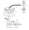
図1は、本発明の第1の実施の形態を示す概念図である。図中、11は光源制御部、12は光源、13は光ファイバ、14は光散乱体、15は反射板、21は受信機、22は受光部、23は復調部である。光源12は、照明用の光を放射するものであり、例えばLEDやレーザダイオードなど、高速な応答特性を有する素子が用いられる。 FIG. 1 is a conceptual diagram showing a first embodiment of the present invention. In the figure, 11 is a light source controller, 12 is a light source, 13 is an optical fiber, 14 is a light scatterer, 15 is a reflector, 21 is a receiver, 22 is a light receiver, and 23 is a demodulator. The
光源制御部11は、送信すべき情報により光源12の点滅あるいは光量を制御する。これによって光源12から変調光を放射させる。 The light
光ファイバ13は、光源12からの光を一端から他端へ導通させる。光ファイバ13の種類としては、グラスファイバとプラスチック光ファイバ(POF)の両方が利用できる。両者を比較した場合、POFの方が軽く、一般的にファイバ径を大きくできるため,POFの単位断面積あたりの光のエネルギー密度はグラスファイバと比較して低い。従って、より高パワーの光エネルギーを送ることができる。また、POFはグラスファイバと比較して接続が容易であり柔軟性がある。 The
光散乱体14は、光ファイバ13の端部に設けられており、光ファイバ13を導通してきた光を散乱放射する。光散乱体14としては、高輝度光散乱ポリマー導光体を用いることができる。高輝度光散乱ポリマー導光体は、例えばフォトニクスポリマー中にミクロンオーダーの不均一構造を形成させた、高輝度光散乱導光体(HSOT)ポリマーで構成することができ、照明器具として高効率な可視光の散乱体となる。光ファイバ13としてPOFを用いた場合、光散乱体14と光ファイバ13がプラスチックで構成されることになるため、両者の一体化することもできる。例えば両者を別々に製造して一体化するほか、製造時の添加剤や製造条件などを調整することにより一体的に製造することも可能である。光散乱体14の形状は任意であり、例えば図1においては半球形の形状とし、その中心に光ファイバ13の端部を接続している。 The
反射板15は、光散乱体14と対向する面が鏡面によって構成されており、光散乱体14の上部からの散乱光を再び光散乱体14に戻して、光散乱体14の下部からの散乱光を増加させている。この反射板15は、別部材で設けるほか、反射させる面に反射材料を塗布したり蒸着させるなどにより反射面を形成してもよい。なお、この例では図1に示したような半球形状の光散乱体14を用いて、例えば室内の天井などから照明を行う場合を想定している。このような場合、半球の平面部分は天井側となり、この面からの散乱光の放射は不要であるため、光散乱体14の平面部分に反射板15を設けて照明効率を向上させている。しかし、照明の形態や照明光率を向上させる必要がない場合などでは、この反射板15を設けずに構成することもできる。 The reflecting
受信機21は、上述のように光ファイバ13を通じて光散乱体14から放射された、変調された散乱光を受光して、送られてきた情報を受信する。そのための構成として、受光部22及び復調部23などを含んで構成されている。受光部22は、光ファイバ13を通じて光散乱体14から放射された、変調された散乱光を受光して電気信号に変換し、復調部23に送る。復調部23では、受光部22で受光した光量に応じた電気信号を復調し、元の情報を取り出す。これによって、送られてきた情報を受信することができる。 The
上述の本発明の第1の実施の形態における動作の一例について説明する。本発明では、情報を送らない場合にはそのまま照明装置として利用することができる。すなわち、光源12から放射された光を光ファイバ13に入射させ、光ファイバ13を導通して光散乱体14へ入射する。光散乱体14では、光ファイバ13から入射された光を散乱し、散乱光を放射する。なお、半球形状の上部平面から放射される光は、反射板15により反射されて再び光散乱体14に入射され、散乱放射されることになる。このようにして光散乱体14によって散乱され、放射された放射光を照明光として用いればよい。 An example of the operation in the above-described first embodiment of the present invention will be described. In the present invention, when information is not sent, it can be used as it is as a lighting device. That is, the light radiated from the
このように照明装置として用いる場合でも、光ファイバ13の出射端に光散乱体14が設けられ、光ファイバ13を通ってきた光は散乱光として放射される。そのため、単位面積あたりの輝度は光ファイバ13端から直接照射する方法などと比べて低くなる。従って、直視してもそれほどのまぶしさを感じない。また、光散乱体14によって、広い範囲を照明することができる。 Thus, even when used as a lighting device, the
さらに、光散乱体14と光ファイバ13を一体化して構成した場合、室内には光散乱体14を設置するだけでよく、従来の照明器具のように大型の器具を設置する必要がなくなる。また、光源12はどこに存在していても、光を光ファイバ13で送ればよいため、従来の照明器具のように室内に光源を設けなくてもよい。従って、例えば電気ショートなどが問題となる場所において利用する場合は、別室に光源12を設けて当該場所まで光ファイバ13を敷設し、照明として利用することも可能である。これによって、漏電やショートなどの問題は発生せず、安全に照明することができる。 Furthermore, when the
情報を送信する際には、その送信すべき情報を光源制御部11に与える。光源制御部11は、受け取った送信すべき情報により光源12の点滅あるいは光量を制御し、これによって送信すべき情報に従って変調された光が光源12から放射される。上述の照明の場合と同様に、光源12から放射された変調光は光ファイバ13に入射され、光ファイバ13を導通して光散乱体14へ入射される。光散乱体14では、光ファイバ13から入射された変調光を散乱し、散乱光を放射する。光散乱体14で散乱が起きても、変調時の周波数が光の周波数に比べて低ければ、影響を受けることはない。従って変調された散乱光が光散乱体14から放射されることになる。 When transmitting information, the information to be transmitted is given to the light
また、上述のように光源12として高速応答特性を有する素子を用いているので、光源制御部11による高速な点滅あるいは光量制御が可能であり、光散乱体14から放射される変調された散乱光も、高速に点滅あるいは光量変動することになる。しかし、点滅あるいは光量変動が行われても、それが高速であると人の目には点滅や光量の変動は感知されず、ほぼ一定の光量で光っているように見える。従って、光散乱体14から放射される散乱光は、変調されていてもそのまま照明光として利用することができる。 Further, since an element having a high-speed response characteristic is used as the
情報を受信する場合には、光散乱体14から放射される変調された散乱光を、受信機21の受光部22によって受光すればよい。受光部22で受光された光は電気信号に変換され、復調部23に渡される。そして復調部23で復調することによって、情報を取得することができる。 When information is received, the modulated scattered light emitted from the
このようにして、照明を行うとともに情報の伝送を行うことができる。従来の光ファイバを用いた通信では、受信機まで光ファイバを引き回す必要があり、受信機を移動させることは困難である。しかし本発明では、照明光が受光できる場所であればどこでも情報を受け取ることができる。また光ファイバと直接接続されている必要がないため、受信機は移動可能である。例えば携帯端末に受信機21を組み合わせて利用することも可能である。また、既存の赤外線通信や無線通信などの場合には、照明器具とは別に専用の送信機を設ける必要があった。しかし本発明では、通常、室内に設けられる照明器具として光散乱体14を設け、電線の代わりに光ファイバ13を敷設することによって、照明とともに通信を行うことができる。 In this way, illumination can be performed and information can be transmitted. In conventional communication using an optical fiber, it is necessary to route the optical fiber to the receiver, and it is difficult to move the receiver. However, according to the present invention, information can be received anywhere as long as illumination light can be received. Also, the receiver is movable because it does not need to be directly connected to the optical fiber. For example, a portable terminal can be used in combination with the
また、光散乱体14によって散乱光を放出するため、照明範囲を広くすることができることから、通信可能な範囲も広くできる。さらに、照明を行うためには数ワットから数十ワットといった高いパワーが必要とされるが、そのパワーを通信に利用できるため、高速、高品質の通信を行うことが可能である。 Further, since the scattered light is emitted by the
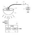
図2は、本発明の第1の実施の形態における第1の変形例を示す概念図である。図中の符号は図1と同様であり、重複する説明を省略する。上述のような構成では、受信機21が照明光を受光できれば通信を行うことができるので、光散乱体14の形状などは任意であり、種々の形状のものを利用することができる。この第1の変形例では、一例として、平板状の光散乱体14を用いた例を示している。なお、光散乱体14が平板状であることを除いては、構成及び動作とも上述と同様である。 FIG. 2 is a conceptual diagram showing a first modification of the first embodiment of the present invention. The reference numerals in the figure are the same as those in FIG. 1, and duplicate description will be omitted. In the above-described configuration, communication can be performed as long as the
このような平板状の光散乱体14を用いることによって、光ファイバ13から光散乱体14に入射された光は、水平方向に散乱されてゆくとともに、垂直方向に散乱された光が平面から放射されることになる。この平面から放射される散乱光を照明光として利用することによって、二次元状の照明光源として利用することが可能となる。これによって、光散乱体14の厚さ程度という、非常に薄型の照明装置を実現することができる。 By using such a
なお、散乱光の放射が不要である面がある場合には、その面に図1に示した反射板15あるいは反射板15に相当する反射面を形成してもよい。図2に示した例では、平板状の光散乱体14の上面に反射板15を設けた例を示している。この反射板15によって、光散乱体14の上面から放射される散乱光を再び光散乱体14に戻し、照明効率を向上させることができる。 When there is a surface that does not require the emission of scattered light, the reflecting
また、光ファイバ13を通ってきた光は直進性があり、1枚の光散乱体14のみでは十分な散乱を行えない場合がある。このような場合には、複数枚の光散乱体14を重ねて用いるとよい。これによって、散乱角が増加し、より広い角度範囲により均一な散乱光を放射することができるようになる。また、光散乱体14の光ファイバ13との接続面と対向する面に反射板を設け、直進してくる光を反射して方向を変え、十分な散乱を行わせることもできる。あるいは、散乱体14の複数方向から複数の光ファイバにより光を入射することによっても、十分な散乱を得ることができる。 Further, the light that has passed through the
図3は、本発明の第1の実施の形態における第2の変形例を示す概念図である。図中の符号は図1と同様であり、重複する説明を省略する。16は蛍光体である。この第2の変形例では、光源12として紫外線もしくは青色のLEDあるいはレーザダイオードを用いる。また、光散乱体14には蛍光体16を混入しておく。 FIG. 3 is a conceptual diagram showing a second modification of the first embodiment of the present invention. The reference numerals in the figure are the same as those in FIG. 1, and duplicate description will be omitted.
光源12から放射される紫外線または青色光は、光ファイバ13を通じて光散乱体14に入射する。すると、蛍光灯などと同様に、入射した紫外線または青色光により光散乱体14内の蛍光体16が励起して白色光が放出される。この白色光が光散乱体14から放射される。この光散乱体14から放射される光を照明光として用い、照明を行うことができる。また、光源12を送信すべき情報に従って点滅あるいは光量制御することによって、光源12から変調された紫外線または青色光を放射させれば、光散乱体14から変調された白色光が放射されるので、これを受信機21の受光部22で受光すれば、情報の伝送を行うことができる。 Ultraviolet light or blue light emitted from the
なお、この場合の光散乱体14は、図3に示すような半球形状に限らず図2に示すような平板状など、種々の形態が可能である。 In this case, the
図4は、本発明の第2の実施の形態を示す概念図である。図中の符号は図1と同様であり、重複する説明を省略する。この第2の実施の形態では、複数本の光ファイバ13を1つの光散乱体14に接続し、それぞれの光ファイバ13に対して、それぞれ、異なる波長の光を導通させる例を示している。図4に示した例では、光源12として赤、緑、青の光源を用い、3本の光ファイバ13のそれぞれに各光源12から放射される色の光を入射している。 FIG. 4 is a conceptual diagram showing a second embodiment of the present invention. The reference numerals in the figure are the same as those in FIG. 1, and duplicate description will be omitted. In the second embodiment, an example is shown in which a plurality of
それぞれの光ファイバ13に入射された赤、緑、青の光は、それぞれの光ファイバ13を通じて光散乱体14に入射される。光散乱体14に入射されたそれぞれの色の光は、光散乱体14の中で散乱されることで混合され、白色光となって放射される。従って、光散乱体14から放射される光を照明光として用いる場合、白色光源として利用することができる。もちろん、白色光源として用いるほか、それぞれの色の光の強さを調整することによって、任意の色の照明光を作り出すことができる。 The red, green, and blue light incident on each
通信を行う際には、これら複数の光源12を同時に駆動制御するほか、一部のみを駆動制御することでも実現可能である。図4に示した例では、赤の光を発光するLEDまたはレーザダイオードのみを駆動制御し、ほかの緑、青のLEDまたはレーザダイオードについては駆動制御を行わない例を示している。このようにすれば、赤色の光のみが変調され、他の色の光は変調されないことになる。例えば受信機21の受光部22の感度が赤色や赤外にピークを有する場合などは、このような構成が有効である。 When performing communication, it can be realized by controlling the driving of the plurality of
このように一部の色の光について変調した場合、受信機21では、その変調された光成分を受光して復調することが望ましい。例えば図4に示した例のように赤色光について変調をかけた場合、赤色光を透過するフィルタを設けたり、赤色光に高い受光感度を有する受光部22を用いたり、プリズムを用いて赤色光を分光するなど、種々の公知の方法によって赤色光を選択的に受光し、復調部23で復調すれば、より確実に情報を受信することができる。 When the light of some colors is modulated as described above, it is desirable that the
なお、複数本の光ファイバ13に送通する光は任意であり、上述のような赤、緑、青の光に限られるものではないし、その光の強度も自由に変更可能である。例えばすべて同じ色の光とし、光量を増加させることも可能である。また、上述のように赤、緑、青の光源12を用いる場合、1本の光ファイバ13に3色の光を入射させるように構成してもよい。また、情報を送信する際に変調する光の色も赤色に限られるものではなく、他の1色以上の光について変調すればよい。 The light transmitted through the plurality of
また、図4に示した構成において、それぞれの光源12を、それぞれ異なる情報に従って個別に駆動制御し、複数の情報を送信することもできる。すなわち、赤色光により情報1を送信し、緑色光により情報2を送信し、青色光により情報3を送信するといったことが可能である。この場合も受信機21の側で受光する光の色を選択すれば、選択した色の光によって送信されてきた情報を受信することができる。 Further, in the configuration shown in FIG. 4, each of the
さらに、例えば照明用の光を送通する1ないし複数本の光ファイバ13のほかに、情報送信用の光ファイバを設け、当該光ファイバに対応する光源を制御して情報を送信するように構成することもできる。この場合、例えば白色光源を用いることによって照明光の色を変えずに情報を送信することができる。また、例えば赤外光を利用することによって、赤外線による情報の送信も可能である。 Further, for example, in addition to one or more
図5は、本発明の第2の実施の形態の変形例を示す概略構成図である。一部の色の光だけに変調をかける場合、例えば図5に示したように、駆動制御部11によって駆動制御を行う光源12のみについて光ファイバ13を通じて光散乱体14に変調光を供給し、その他の色を発光する光源12については発光光を光散乱体14に直接入射させる構成も可能である。この場合でも光散乱体14内で入射された色の光が混合されて合成され、照明光として用いることができる。それとともに、特定色の光については変調されており、この光成分を受信機21の受光部22で受光して復調部23で復調することにより、情報を受信することができる。図5では赤色光に変調をかける例を示しているが、これに限らず、青、緑の光に変調をかけてもよいし、また3色のうちいずれか2色に変調をかけてもよい。 FIG. 5 is a schematic configuration diagram showing a modified example of the second embodiment of the present invention. When modulating only light of a part of the colors, for example, as shown in FIG. 5, only the
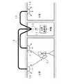
図6は、本発明の応用例の説明図である。この例では複数の室内に情報を配信する例を示している。上述のように本発明では照明器具としても用いることができる。そのため、室内の天井に光散乱体14を設置した例を示している。照明光により通信を行う場合、影ができると通信品質が低下する。このように天井に光散乱体14を設置した場合、人や物などによる影ができにくいため、シャドウイングの問題を極力回避することができる。 FIG. 6 is an explanatory diagram of an application example of the present invention. This example shows an example in which information is distributed to a plurality of rooms. As described above, the present invention can also be used as a lighting fixture. Therefore, an example in which the
また、A室では光散乱体14を複数設置した例を示している。このように光散乱体14を複数設置することによって、さらに影の影響を低減することが可能である。このように光散乱体14を複数設置する場合、同じ光源から複数の光散乱体14へ光ファイバ13により変調光を送ることができる。そのため、照明装置毎に光源制御部11や光源を設ける必要はなく、送信機の設置コストを大幅に低減することができる。もちろん、複数の光散乱体14から異なる情報を送信するように構成することも可能であり、その場合には受信機21側で受光する照明光を選択することによって受信する情報を選択することができる。 In the room A, an example in which a plurality of
さらにB室にも同様に光散乱体14を設置している。このとき、A室と同じ光源から変調光をB室にも送ることができる。従って、部屋が異なっていても同じ情報を配信することが可能である。この場合、部屋が異なっても光源制御部11を共通化でき、さらには光源12についても共通化することができる。 Further, the
なお、上述の第1及び第2の実施の形態においては、一方向の情報の伝送を行うものとして説明した。しかし、光ファイバ13は双方向に光を導通することから、双方向の通信も可能である。すなわち、光散乱体14の外部に存在する光源が発光した光は、光散乱体14から光ファイバ13を通じて光源12の端から出射される。これを利用し、光散乱体14の外部に存在する光源を駆動制御し、変調光を発光させる。この変調光は光ファイバ13を通じて光源12の側の端から出射されることになる。光源12と光ファイバ13の端との間に例えばハーフミラーなどの光分離手段を設けておき、光ファイバ13の光源12側の端から出射される光を分離して受光し、復調すれば送られてきた情報を受信することができる。これによって、双方向の通信が可能となる。なお、光散乱体14を通じて光ファイバ13に入射される光量は、光散乱体14の散乱により非常に微弱となるが、受光感度の向上や信号の識別技術の向上によって十分実現可能である。 In the above-described first and second embodiments, it has been described that information is transmitted in one direction. However, since the
1…光源、2…光ファイバ、11…光源制御部、12…光源、13…光ファイバ、14…光散乱体、15…反射板、16…蛍光体、21…受信機、22…受光部、23…復調部。 DESCRIPTION OF
Claims (6)
Translated fromJapanesePriority Applications (27)
| Application Number | Priority Date | Filing Date | Title |
|---|---|---|---|
| JP2003323052AJP2004229273A (en) | 2003-09-16 | 2003-09-16 | Communication method using illumination light |
| CN200910179120ACN101714898A (en) | 2002-10-24 | 2003-10-23 | Illumination light communication device |
| US10/532,250US7583901B2 (en) | 2002-10-24 | 2003-10-23 | Illuminative light communication device |
| EP03758809AEP1564914B1 (en) | 2002-10-24 | 2003-10-23 | Illumination light communication device |
| EP07017127AEP1858179A1 (en) | 2002-10-24 | 2003-10-23 | Illumination light communication device |
| DE60331271TDE60331271D1 (en) | 2002-10-24 | 2003-10-23 | Device for lighting and data transmission |
| EP07017126AEP1860801A1 (en) | 2002-10-24 | 2003-10-23 | Illumination light communication device |
| AU2003275606AAU2003275606A1 (en) | 2002-10-24 | 2003-10-23 | Illumination light communication device |
| HK06107882.0AHK1087848B (en) | 2002-10-24 | 2003-10-23 | Illumination light communication device |
| EP07017123AEP1865631B1 (en) | 2002-10-24 | 2003-10-23 | Illumination light communication device |
| EP07016825AEP1855398B1 (en) | 2002-10-24 | 2003-10-23 | Illumination light communication device |
| EP07017124AEP1863203A1 (en) | 2002-10-24 | 2003-10-23 | Illumination light communication device |
| DE60316178TDE60316178T2 (en) | 2002-10-24 | 2003-10-23 | COMMUNICATION DEVICE WITH ILLUMINATING LIGHT |
| KR1020057007071AKR100970034B1 (en) | 2002-10-24 | 2003-10-23 | Illumination optical communication device |
| EP07017125AEP1860800A1 (en) | 2002-10-24 | 2003-10-23 | Illumination light communication device |
| CN 200810130495CN101350666B (en) | 2002-10-24 | 2003-10-23 | Illumination light communication device |
| DE60336770TDE60336770D1 (en) | 2002-10-24 | 2003-10-23 | Communication device with illumination light |
| EP07017122AEP1860799A1 (en) | 2002-10-24 | 2003-10-23 | Illumination light communication device |
| PCT/JP2003/013539WO2004038962A1 (en) | 2002-10-24 | 2003-10-23 | Illumination light communication device |
| AT03758809TATE372614T1 (en) | 2002-10-24 | 2003-10-23 | COMMUNICATION DEVICE WITH ILLUMINATION LIGHT |
| TW93127907ATW200524309A (en) | 2003-09-16 | 2004-09-15 | Method and computer program including program code means, and computer program product for describing a propagation behavior of a communication signal that is transmitted by a base station in a communication network |
| HK09106578.8AHK1129164B (en) | 2002-10-24 | 2009-07-20 | Illumination light communication device |
| US12/461,227US20090297166A1 (en) | 2002-10-24 | 2009-08-05 | Illuminative light communication device |
| US12/461,229US7929867B2 (en) | 2002-10-24 | 2009-08-05 | Emergency lamp and wireless emergency lamp data transmission system |
| US12/461,223US20090297167A1 (en) | 2002-10-24 | 2009-08-05 | Illuminative light communication device and lighting device |
| US12/461,226US20090297156A1 (en) | 2002-10-24 | 2009-08-05 | Illuminative light communication system, lighting device and illuminative light source |
| US12/461,225US20090310976A1 (en) | 2002-10-24 | 2009-08-05 | Illuminative light communication system |
Applications Claiming Priority (1)
| Application Number | Priority Date | Filing Date | Title |
|---|---|---|---|
| JP2003323052AJP2004229273A (en) | 2003-09-16 | 2003-09-16 | Communication method using illumination light |
Related Child Applications (1)
| Application Number | Title | Priority Date | Filing Date |
|---|---|---|---|
| JP2006250686ADivisionJP2007004203A (en) | 2006-09-15 | 2006-09-15 | Light transmission body |
Publications (1)
| Publication Number | Publication Date |
|---|---|
| JP2004229273Atrue JP2004229273A (en) | 2004-08-12 |
Family
ID=32906139
Family Applications (1)
| Application Number | Title | Priority Date | Filing Date |
|---|---|---|---|
| JP2003323052APendingJP2004229273A (en) | 2002-10-24 | 2003-09-16 | Communication method using illumination light |
Country Status (2)
| Country | Link |
|---|---|
| JP (1) | JP2004229273A (en) |
| TW (1) | TW200524309A (en) |
Cited By (10)
| Publication number | Priority date | Publication date | Assignee | Title |
|---|---|---|---|---|
| WO2006103856A1 (en)* | 2005-03-25 | 2006-10-05 | Nikon Corporation | Illuminator, imager, and imaging system |
| JP2010518587A (en)* | 2007-02-12 | 2010-05-27 | インテマティックス・コーポレーション | Light-emitting diode lamp system |
| US7929867B2 (en) | 2002-10-24 | 2011-04-19 | Nakagawa Laboratories, Inc. | Emergency lamp and wireless emergency lamp data transmission system |
| JP2011523182A (en)* | 2008-06-09 | 2011-08-04 | フェデラル−モーグル コーポレイション | Headlamp assembly and its accent lighting |
| JP2011192932A (en)* | 2010-03-16 | 2011-09-29 | Kinki Univ | Light emitting device, lighting device, display device, marking device, optical communication system, and optical communication method |
| JP2013510645A (en)* | 2009-11-11 | 2013-03-28 | アルコン リサーチ, リミテッド | Structured illumination probe and method |
| US8613537B2 (en) | 2010-05-28 | 2013-12-24 | Mitsubishi Electric Corporation | Display and illumination system |
| US8807799B2 (en) | 2010-06-11 | 2014-08-19 | Intematix Corporation | LED-based lamps |
| KR101497459B1 (en)* | 2013-07-19 | 2015-03-03 | 삼성중공업 주식회사 | Optical lighting system |
| US9749046B2 (en) | 2014-09-17 | 2017-08-29 | Fujitsu Limited | Signal transmission device, signal transmission method, signal reception device, and communication system |
Citations (12)
| Publication number | Priority date | Publication date | Assignee | Title |
|---|---|---|---|---|
| JPS5938253A (en)* | 1982-08-27 | 1984-03-02 | Mitsubishi Rayon Co Ltd | Light-diffusing acrylic resin molding |
| JPS63269106A (en)* | 1987-04-28 | 1988-11-07 | Mitsubishi Rayon Co Ltd | plastic optics |
| JPH05302006A (en)* | 1991-07-04 | 1993-11-16 | Mitsubishi Rayon Co Ltd | Light-diffusing methacrylic resin |
| JPH1066167A (en)* | 1996-08-15 | 1998-03-06 | Sony Corp | Remote controller |
| JPH11234210A (en)* | 1997-12-11 | 1999-08-27 | Nippon Telegr & Teleph Corp <Ntt> | Optical distribution system |
| JP2002148442A (en)* | 2000-11-14 | 2002-05-22 | Nichia Chem Ind Ltd | Light emitting device |
| JP2002261334A (en)* | 2000-05-17 | 2002-09-13 | Nichia Chem Ind Ltd | Light emitting device and device |
| JP2002274860A (en)* | 2001-03-12 | 2002-09-25 | Olympus Optical Co Ltd | Light scattering glass material and its manufacturing method |
| JP2002290335A (en)* | 2001-03-28 | 2002-10-04 | Sony Corp | Optical space transmitter |
| JP2003318836A (en)* | 2002-04-23 | 2003-11-07 | Keio Gijuku | Illumination light transmitting device, illumination light receiving device, and phosphor type illumination light communication system |
| JP2004282389A (en)* | 2003-03-14 | 2004-10-07 | Global Com:Kk | Illumination light communication device and illumination element |
| JP2004363756A (en)* | 2003-06-03 | 2004-12-24 | Sharp Corp | Illumination device with light transmission mechanism |
- 2003
- 2003-09-16JPJP2003323052Apatent/JP2004229273A/enactivePending
- 2004
- 2004-09-15TWTW93127907Apatent/TW200524309A/enunknown
Patent Citations (12)
| Publication number | Priority date | Publication date | Assignee | Title |
|---|---|---|---|---|
| JPS5938253A (en)* | 1982-08-27 | 1984-03-02 | Mitsubishi Rayon Co Ltd | Light-diffusing acrylic resin molding |
| JPS63269106A (en)* | 1987-04-28 | 1988-11-07 | Mitsubishi Rayon Co Ltd | plastic optics |
| JPH05302006A (en)* | 1991-07-04 | 1993-11-16 | Mitsubishi Rayon Co Ltd | Light-diffusing methacrylic resin |
| JPH1066167A (en)* | 1996-08-15 | 1998-03-06 | Sony Corp | Remote controller |
| JPH11234210A (en)* | 1997-12-11 | 1999-08-27 | Nippon Telegr & Teleph Corp <Ntt> | Optical distribution system |
| JP2002261334A (en)* | 2000-05-17 | 2002-09-13 | Nichia Chem Ind Ltd | Light emitting device and device |
| JP2002148442A (en)* | 2000-11-14 | 2002-05-22 | Nichia Chem Ind Ltd | Light emitting device |
| JP2002274860A (en)* | 2001-03-12 | 2002-09-25 | Olympus Optical Co Ltd | Light scattering glass material and its manufacturing method |
| JP2002290335A (en)* | 2001-03-28 | 2002-10-04 | Sony Corp | Optical space transmitter |
| JP2003318836A (en)* | 2002-04-23 | 2003-11-07 | Keio Gijuku | Illumination light transmitting device, illumination light receiving device, and phosphor type illumination light communication system |
| JP2004282389A (en)* | 2003-03-14 | 2004-10-07 | Global Com:Kk | Illumination light communication device and illumination element |
| JP2004363756A (en)* | 2003-06-03 | 2004-12-24 | Sharp Corp | Illumination device with light transmission mechanism |
Cited By (12)
| Publication number | Priority date | Publication date | Assignee | Title |
|---|---|---|---|---|
| US7929867B2 (en) | 2002-10-24 | 2011-04-19 | Nakagawa Laboratories, Inc. | Emergency lamp and wireless emergency lamp data transmission system |
| WO2006103856A1 (en)* | 2005-03-25 | 2006-10-05 | Nikon Corporation | Illuminator, imager, and imaging system |
| JP2010518587A (en)* | 2007-02-12 | 2010-05-27 | インテマティックス・コーポレーション | Light-emitting diode lamp system |
| US8538217B2 (en) | 2007-02-12 | 2013-09-17 | Intematix Corporation | Light emitting diode lighting system |
| JP2013243139A (en)* | 2007-02-12 | 2013-12-05 | Intematix Corp | Light emitting diode lighting system |
| JP2011523182A (en)* | 2008-06-09 | 2011-08-04 | フェデラル−モーグル コーポレイション | Headlamp assembly and its accent lighting |
| JP2013510645A (en)* | 2009-11-11 | 2013-03-28 | アルコン リサーチ, リミテッド | Structured illumination probe and method |
| JP2011192932A (en)* | 2010-03-16 | 2011-09-29 | Kinki Univ | Light emitting device, lighting device, display device, marking device, optical communication system, and optical communication method |
| US8613537B2 (en) | 2010-05-28 | 2013-12-24 | Mitsubishi Electric Corporation | Display and illumination system |
| US8807799B2 (en) | 2010-06-11 | 2014-08-19 | Intematix Corporation | LED-based lamps |
| KR101497459B1 (en)* | 2013-07-19 | 2015-03-03 | 삼성중공업 주식회사 | Optical lighting system |
| US9749046B2 (en) | 2014-09-17 | 2017-08-29 | Fujitsu Limited | Signal transmission device, signal transmission method, signal reception device, and communication system |
Also Published As
| Publication number | Publication date |
|---|---|
| TW200524309A (en) | 2005-07-16 |
Similar Documents
| Publication | Publication Date | Title |
|---|---|---|
| US20090310976A1 (en) | Illuminative light communication system | |
| US11879616B2 (en) | Adjustable-beam luminaires | |
| CN100563130C (en) | Illuminating light communication device | |
| CN103649631A (en) | A lighting system for providing a daylight appearance and a luminaire | |
| US20150309248A1 (en) | Led-based lighting devices and systems based on light panels having transparent waveguides | |
| JP2018010755A (en) | Lighting device | |
| US20190376653A1 (en) | Device for lighting and optical communication combined with viewing of the communication field | |
| JP2004229273A (en) | Communication method using illumination light | |
| JP4450303B2 (en) | Illumination light communication device and illumination element | |
| CN106838650A (en) | led light | |
| JP2004297295A (en) | Illumination light communication system and illumination device, illumination light source | |
| JP2007004203A (en) | Light transmission body | |
| CN110366832A (en) | Liquid Crystal Beam Steering | |
| CN207279308U (en) | led light | |
| WO2015125557A1 (en) | Illumination device | |
| KR200445910Y1 (en) | Lens for light emitting diode lighting | |
| JPH06132901A (en) | Remote control device | |
| HK1129167A (en) | Illumination light communication device | |
| HK1143669A (en) | Illumination light communication device | |
| HK1129164B (en) | Illumination light communication device | |
| HK1087848B (en) | Illumination light communication device | |
| HK1129165A (en) | Illumination light communication device | |
| ES2183666A1 (en) | Focus unit for the scenery or theatre show colour lighting |
Legal Events
| Date | Code | Title | Description |
|---|---|---|---|
| A711 | Notification of change in applicant | Free format text:JAPANESE INTERMEDIATE CODE: A711 Effective date:20050225 | |
| A621 | Written request for application examination | Free format text:JAPANESE INTERMEDIATE CODE: A621 Effective date:20060915 | |
| A131 | Notification of reasons for refusal | Free format text:JAPANESE INTERMEDIATE CODE: A131 Effective date:20080702 | |
| A02 | Decision of refusal | Free format text:JAPANESE INTERMEDIATE CODE: A02 Effective date:20081029 |