JP2004227735A - Servo track writing method and magnetic disk drive - Google Patents
Servo track writing method and magnetic disk driveDownload PDFInfo
- Publication number
- JP2004227735A JP2004227735AJP2003017561AJP2003017561AJP2004227735AJP 2004227735 AJP2004227735 AJP 2004227735AJP 2003017561 AJP2003017561 AJP 2003017561AJP 2003017561 AJP2003017561 AJP 2003017561AJP 2004227735 AJP2004227735 AJP 2004227735A
- Authority
- JP
- Japan
- Prior art keywords
- magnetic disk
- servo track
- writing
- magnetic
- magnetic head
- Prior art date
- Legal status (The legal status is an assumption and is not a legal conclusion. Google has not performed a legal analysis and makes no representation as to the accuracy of the status listed.)
- Pending
Links
Images


Landscapes
- Moving Of The Head To Find And Align With The Track (AREA)
Abstract
Translated fromJapaneseDescription
Translated fromJapanese【0001】
【発明の属する技術分野】
本発明は、磁気記録方式として垂直記録方式を用いた磁気ディスク装置における、円板状の磁気ディスクへのサーボトラック書き込み方法、ならびに、磁気記録方式として垂直記録方式を用いた磁気ディスク装置に関する。
【0002】
【従来の技術】
磁気ディスク装置における記録密度を飛躍的に向上させる磁気記録方式として、記録媒体を厚み方向に磁化する垂直記録方式(垂直磁気記録方式)が提案されている。この方式を用いる磁気ディスク装置は、一般的には、軟磁性層の上に記録層を積層した2層記録媒体等が表面に形成された円板状の磁気ディスクを回転させ、ボイスコイルモータ等のロータリアクチュエータで回転(旋回)される磁気ヘッド(書き込み用の単磁極ヘッド)でもって、記録層に膜厚方向の磁界を加え、情報の記録を行うように構成されている。
【0003】
磁気ディスクには、磁気ヘッドの位置決めを行うためのサーボトラック(サーボ情報)が書き込まれている。このサーボトラックの書き込み作業は、たとえば、磁気ディスクや磁気ヘッドおよびキャリッジアーム駆動部が組み込まれた製造段階の磁気ディスク装置に対して、プッシュ・ピン方式等のサーボトラックライタ(STW)を用いてなされる。
【0004】
プッシュ・ピン方式のサーボトラックライタは、磁気ヘッドを支持する磁気ディスク装置内のキャリッジアームを押動して回転させるためのピンをアーム先端に有したアクチュエータを備え、このアクチュエータでもって磁気ディスク装置内のキャリッジアームを回転させ、磁気ヘッドを位置決めしながら、磁気ディスクにサーボトラックを書き込ませるものである。(たとえば、特許文献1参照)。
【0005】
【特許文献1】
特開2002−304862号公報(図1)
【0006】
【発明が解決しようとする課題】
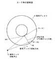
キャリッジアームを用いて磁気ヘッドを磁気ディスクのトラック幅方向(磁気ディスクの半径方向)に移動させる場合、ヨー角(yaw角)が変化する。ここで、ヨー角は、トラックの接線と磁気ヘッドとのなす角度であり、図7に示すような位置関係において、磁気ヘッドが磁気ディスクDのアウタ側の位置H0にある時は、磁気ヘッドが接線に対して時計方向に回転しているので、そのヨー角θ=θ0は負であり、磁気ヘッドが磁気ディスクDのインナ側の位置H1に移動した時は、磁気ヘッドが接線に対して反時計方向に回転しているので、そのヨー角θ=θ1は正となる。
【0007】
このようにヨー角は、トラック位置により変化し、ヨー角が零でない位置で、記録を行うと、サイドライト(はみ出し記録)がなされることになる。図8はサイドライトの説明図で、(a)はヨー角θ=0(零)における磁気ヘッド(単磁極ヘッド)による磁化パターンを概念的に示したもので、図8における右方向が磁気ディスクの回転方向であり、左方向が磁気ヘッドの相対的な移動方向である。この例では、ライトコア幅Bの磁気ヘッドHを用いて、磁気ディスクD上に、トラック方向の長さLのN極とS極を交互に書き込む場合を示している。(a)から明らかなように、ヨー角θが零ではサイドライトは生じない。
【0008】
一方、ヨー角θが零でない場合は、たとえば図8(b)に示すように、ディスクの回転方向(トラックの接線方向)に対して磁気ヘッドHが傾くことになり、サイドライトが生じる。サイドライトが生じた磁化パターンをMRヘッド等の読み取り用の磁気ヘッドで再生すると、サイドライト部分の影響で、本来の信号極性を読み誤る場合がある。
【0009】
特に、製造段階においてサーボセクタにサーボ情報(磁化パターン)をサーボトラックライタでもって書き込む場合は、サーボ情報の中に、トラックに対する磁気ヘッドの相対的な位置を示すバーストコードと呼ばれる磁化パターンがあるため、このバーストコードにサイドライトの影響が出てしまい、製品となった磁気ディスク装置において、正しい位置情報が得られず、磁気ヘッドの正確な位置決め動作が困難になる場合がある。
【0010】
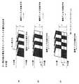
図9は、サイドライトのバーストコードへの影響を概念的に示す図で、(a)はヨー角θが零の場合を示し、(b)はヨー角θが零でない場合を示している。バーストコードは、規定の幅(通常、トラック幅tの2/3)でもって正確に書き込む必要がある。図9の例では、磁気ヘッド(書き込み用の単磁極ヘッド)をトラック幅tの1/3のピッチでトラック幅方向(図9における下方)に、▲1▼,▲2▼,▲3▼のステップで送り、ステップ▲2▼および▲3▼で形成した磁化パターンで書き継がれた部分(白黒部分)をバーストコードBCとしている。
【0011】
ヨー角θが零の場合は、図9(a)に示すように、サイドライトの影響は受けず、本来のバーストコードBCの磁化パターンが形成されている。しかし、ヨー角θが零でない場合は、図9(b)に示すように、ステップ▲2▼および▲3▼で生じたサイドライトの影響は受け、理想的なバーストコードBCの磁化パターンは得られない。すなわち、ステップ▲2▼での磁化パターン形成においてサイドライトが生じるだけでなく、ステップ▲3▼での磁化パターン形成時に、新たなサイドライトが正常な磁化パターン部分を上書きし、本来のバーストコードBCの磁化パターンが形成されないことになる。
【0012】
インナ側およびアウタ側での磁気ヘッドのヨー角は、磁気ディスクと磁気ヘッドおよびキャリッジアーム等の位置関係により、その符号や絶対値が変化する。一方、プッシュ・ピン方式のサーボトラックライタによるサーボトラックの書き込みは、通常、アウタ側からインナ側の一方向に磁気ヘッドを移動させながら行われる。このため、磁気ヘッドの送り方向(STW方向)が、図9(b)での磁気ヘッド送り方向と一致することがあり、この場合には、正確にサーボトラックを書き込めないことになる。
【0013】
本発明はこのような問題を解決するもので、サーボトラックを正確に書き込めるサーボトラック書き込み方法を実現することを目的とするものである。
【0014】
本発明の他の目的は、データのリード/ライト時に磁気ヘッドを正確に位置決めできる磁気ディスク装置を実現することである。
【0015】
【課題を解決するための手段】
請求項1に係る発明は、磁気記録方式として垂直記録方式を用いた磁気ディスク装置における、円板状の磁気ディスクへのサーボトラック書き込み方法に関するもので、磁気ディスクのサーボトラックを書き込むエリア上での磁気ヘッドのヨー角が正の範囲では、磁気ヘッドのサーボトラック書き込み時の送り方向を磁気ディスクのインナ側からアウタ側に向かう方向に選び、ヨー角が負の範囲では、磁気ヘッドのサーボトラック書き込み時の送り方向を磁気ディスクのアウタ側からインナ側に向かう方向に選ぶことを特徴とするものである。
【0016】
磁気ディスクのサーボトラックを書き込むエリア上での磁気ヘッドのヨー角が正の範囲では、アウタ側にサイドライトが発生し、負の範囲では、インナ側にサイドライトが発生する。本発明では、磁気ヘッドのサーボトラック書き込み時の送り方向をヨー角の正負のエリアにより反転させ、サイドライトが形成される方向に、磁気ディスクを送るようにしている。このため、サイドライトの無い磁化パターン部分を用いてバーストコードが形成されることになり、サーボトラックを正確に書き込める。
【0017】
請求項2に係る発明は、請求項1記載のサーボトラック書き込み方法において、磁気ディスクのサーボトラックを書き込むエリア内の最もインナ側と最もアウタ側での磁気ヘッドのヨー角を求め、両ヨー角の符号(正/負)が異なる場合には、ヨー角が零の近傍に、サーボトラックの書き込みを行わないダミーゾーンを設け、このダミーゾーンを境にして、ヨー角が正の範囲では、磁気ヘッドのサーボトラック書き込み時の送り方向を磁気ディスクのインナ側からアウタ側に向かう方向に選び、ヨー角が負の範囲では、磁気ヘッドのサーボトラック書き込み時の送り方向を磁気ディスクのアウタ側からインナ側に向かう方向に選ぶことを特徴とするものである。
【0018】
磁気ヘッドのサーボトラック書き込み時の送り方向をヨー角の正負のエリアにより反転させる場合、位置決め精度上の問題から両エリアの接合部で磁化パターンが不連続になったり干渉する場合が考えられる。本発明のようにダミーゾーンを設ければ、互いに逆方向から書き込まれるサーボトラックの干渉を確実に回避できるため、サーボトラックを正確に書き込める。
【0019】
請求項3に係る発明は、磁気記録方式として垂直記録方式を用いた磁気ディスク装置における、円板状の磁気ディスクへのサーボトラック書き込み方法に関するもので、磁気ディスクのサーボトラックを書き込むエリア内の最もインナ側と最もアウタ側での磁気ヘッドのヨー角を求め、両ヨー角の符号が異なりかつ両ヨー角の絶対値の差が一定値以上である場合には、絶対値の大きい方のヨー角の符号が正であれば、磁気ディスク全体にわたって、磁気ヘッドのサーボトラック書き込み時の送り方向を磁気ディスクのインナ側からアウタ側に向かう方向に選び、絶対値の大きい方のヨー角の符号が負であれば、磁気ディスク全体にわたって、磁気ヘッドのサーボトラック書き込み時の送り方向を磁気ディスクのアウタ側からインナ側に向かう方向に選ぶことを特徴とするものである。
【0020】
磁気ディスクのサーボトラックを書き込むエリア内の最もインナ側と最もアウタ側での磁気ヘッドのヨー角の符号が異なりかつ両ヨー角の絶対値の差が一定値以上である場合は、正負の何れか一方のヨー角は小さく、その符号のヨー角のエリアでのサイドライトの影響も小さい。そこで、本発明では、絶対値の小さいヨー角側エリアでのサイドライトの影響は無視し、絶対値の大きいヨー角側の符号に応じて、磁気ヘッドのサーボトラック書き込み時の送り方向を決定し、磁気ディスク全体にわたってサーボトラックの書き込みを行うことで、書き込み作業の簡素化を図っている。
【0021】
請求項4に係る発明は、磁気記録方式として垂直記録方式を用いた磁気ディスク装置における、円板状の磁気ディスクへのサーボトラック書き込み方法に関するもので、磁気ディスクのサーボトラックを書き込むエリア内の最もインナ側と最もアウタ側での磁気ヘッドのヨー角を求め、両ヨー角の符号が異なりかつ両ヨー角の絶対値の差が一定値未満である場合には、ヨー角が零の近傍に、サーボトラックの書き込みを行わないダミーゾーンを設け、このダミーゾーンを境にして、ヨー角が正の範囲では、磁気ヘッドのサーボトラック書き込み時の送り方向を磁気ディスクのインナ側からアウタ側に向かう方向に選び、ヨー角が負の範囲では、磁気ヘッドのサーボトラック書き込み時の送り方向を磁気ディスクのアウタ側からインナ側に向かう方向に選ぶことを特徴とするものである。
【0022】
磁気ディスクのサーボトラックを書き込むエリア内の最もインナ側と最もアウタ側での磁気ヘッドのヨー角を求め、両ヨー角の符号が異なりかつ両ヨー角の絶対値の差が一定値未満である場合は、正負のヨー角の絶対値が共に大きい場合である。本発明では、この場合には、磁気ヘッドのサーボトラック書き込み時の送り方向を、請求項2に係る発明と同様な方法で行うようにし、サーボトラックを正確に書き込めるようにしている。
【0023】
請求項5に係る発明は、磁気記録方式として垂直記録方式を用いた磁気ディスク装置に関するもので、磁気ディスクのサーボトラックを書き込むエリア内の最もインナ側と最もアウタ側での磁気ヘッドのヨー角の符号が異なるように、磁気ディスクと磁気ヘッドの位置関係が設定され、磁気ディスクには、ヨー角が零の近傍に、サーボトラックの書き込みを行わないダミーゾーンが設けられ、さらに、このダミーゾーンを境にして、ヨー角が正の範囲には、磁気ディスクのインナ側からアウタ側に磁気ヘッドを送りながらサーボトラックの書き込みがなされ、ヨー角が負の範囲には、磁気ディスクのアウタ側からインナ側に磁気ヘッドを送りながらサーボトラックの書き込みがなされていることを特徴とするものである。
【0024】
本発明では、磁気ディスクにサーボトラックが正確に書き込まれているので、データのリード/ライト時に磁気ヘッドを正確に位置決めできる。
【0025】
【実施の形態】
(第1の形態例)
本発明に係るサーボトラック書き込み方法によりサーボ情報が書き込まれた磁気ディスクを有した磁気ディスク装置の実施の形態例について、図2を用いて説明する。ここで、図2は、ディスクエンクロージャのカバーを外した状態での磁気ディスク装置の内部構造を示した平面図である。図2において、装置内部を密閉するディスクエンクロージャ1の中央には、垂直磁気記録媒体である円板状の磁気ディスク2が回転可能に配置され、この磁気ディスク2の外周部近傍に、キャリッジアーム3が軸4を中心に回転可能に設けられている。
【0026】
キャリッジアーム3の先端は、サスペンション5が取り付けられ、そこに、磁気ディスク2上のトラックにデータのリード/ライトを行う磁気ヘッド(磁気ヘッドスライダ)6が取り付けられている。磁気ヘッド6は、書き込み用ヘッドとしての単磁極ヘッドと、読み取り用ヘッドとしてのたとえばMRヘッド部とからなる。
【0027】
キャリッジアーム3の基端側には、キャリッジアーム3を回転駆動するロータリアクチュエータ(ボイスコイルモータ)7が設けられている。このロータリアクチュエータ7の構成は、ディスクエンクロージャ1側に磁気ギャップを有する磁気回路を固定し、キャリッジアーム3にボイスコイル(ムービングコイル)を固着したものである。アクチュエータ7内のボイスコイルに駆動電流を流すと、磁気ギャップ内にあるボイスコイル部分に推力が発生し、キャリッジアーム3が回転し、磁気ヘッド6が磁気ディスク2のトラック幅方向Tに移動することになる。磁気ディスク2は図示しないスピンドルモータにより回転駆動される。
【0028】
磁気ディスク2へのサーボトラックの書き込み作業は、たとえば、磁気ディスク2,磁気ヘッド6,キャリッジアーム3およびロータリアクチュエータ7等が組み込まれた製造段階の磁気ディスク装置に対して、プッシュ・ピン方式等のサーボトラックライタ(STW)を用いてなされる。
【0029】
上記磁気ディスク2へのサーボトラックの書き込み方法の形態例を図1を用いて説明する。まず、磁気ディスク2のサーボトラックを書き込むエリア上での磁気ヘッド6のヨー角θが正の範囲では、磁気ヘッド6のサーボトラック書き込み時の送り方向(STW方向)を磁気ディスク2のインナ側からアウタ側に向かう方向に選び、ヨー角θが負の範囲では、磁気ヘッド6のサーボトラック書き込み時の送り方向(STW方向)を磁気ディスク2のアウタ側からインナ側に向かう方向に選ぶ。
【0030】
具体的には、磁気ディスク2のサーボトラックを書き込むエリア内の最もインナ側(H1)と最もアウタ側(H0)での磁気ヘッド6のヨー角θを求め、両ヨー角θの符号(正/負)が異なる場合には、ヨー角θが零の近傍に、サーボトラックの書き込みを行わないダミーゾーンDZを設け、このダミーゾーンDZを境にして、ヨー角θが正の範囲では、磁気ヘッド6のサーボトラック書き込み時の送り方向(STW方向)を磁気ディスク2のインナ側からアウタ側に向かう方向に選び、ヨー角θが負の範囲では、磁気ヘッド6のサーボトラック書き込み時の送り方向(STW方向)を磁気ディスク2のアウタ側からインナ側に向かう方向に選ぶ。
【0031】
図2に示したディスク装置では、図1に示すように、最もインナ側(H1)と最もアウタ側(H0)でのヨー角θの絶対値を同程度に振り分けて、インナ側(H1)とアウタ側(H0)でのサイドライトの発生を均等化しており、たとえば、最もインナ側(H1)でのヨー角θは+8.5°、最もアウタ側(H0)でのヨー角θは−8.5°となっている。このため、ダミーゾーンDZは半径方向の中間位置にある。
【0032】
本形態例でのバーストコードBCの磁化パターン形成について図3および図4を用いて説明する。なお、図3および図4は図9と同様なバーストコードBCを形成する場合を想定したものである。
【0033】
まず、ヨー角θが正の範囲では、磁気ヘッド6のサーボトラック書き込み時の送り方向(STW方向)は、磁気ディスク2のインナ側からアウタ側に向かう方向となる。そこで、磁気ヘッド6を最もインナ側の位置(H1)に移動させてから磁化パターンの書き込みを開始する。ここでの書き込みは、まず図3(a)の位置で磁化パターンを形成後に、図3(b)示すように、磁気ヘッド6をLP(t/3)だけアウタ側に進め、同一極性の磁化パターンを形成する。その後、図3(c)示すように、磁気ヘッド6をさらにLP(t/3)だけアウタ側に進め、反対極性の磁化パターンを形成する。これらの動作の繰り返しにより、トラック幅tの2/3の幅のバーストコードBCが次々に形成される。
【0034】
一方、ヨー角θが負の範囲では、磁気ヘッド6のサーボトラック書き込み時の送り方向(STW方向)は、磁気ディスク2のアウタ側からインナ側に向かう方向となる。そこで、磁気ヘッド6を最もアウタ側の位置(H0)に移動させてから磁化パターンの書き込みを開始する。ここでの書き込みは、図4(a)の位置で磁化パターンを形成後に、図4(b)示すように、磁気ヘッド6をLP(t/3)だけインナ側に進め、同一極性の磁化パターンを形成する。その後、図4(c)示すように、磁気ヘッド6をさらにLP(t/3)だけインナ側に進め、反対極性の磁化パターンを形成する。これらの動作の繰り返しにより、トラック幅tの2/3の幅のバーストコードBCが次々に形成される。
【0035】
上記のインナ側とアウタ側の双方からのサーボトラックの書き込みは、両者の境界に、必要にして十分な幅のダミーゾーンDZが残るまでなされる。上記サーボトラックの書き込み方法によれば、サイドライトが形成される方向に、磁気ヘッド6を送ることになる。このため、サイドライトの無い磁化パターン部分を用いてバーストコードBCが形成されることになり、サーボトラックを正確に書き込むことができる。また、ダミーゾーンDZを設けたことにより、サーボトラックの干渉が確実に回避でき、この点からも、サーボトラックを正確に書き込める。
【0036】
よって、磁気ディスク装置として、データのリード/ライト時に磁気ヘッド6を正確に位置決めできるものが得られることになる。
【0037】
なお、ダミーゾーンDZを設けたことにより、ダミーゾーンDZを越えてシークする場合、ダミーゾーンDZを越える毎に、新たなゾーンにてオントラック処理を行う必要が生じる。図5はこの場合のシーク動作を示している。すなわち、制御部はシーク命令を受け付けると(ステップS1)、目標のトラック位置がダミーゾーンDZを越えるか否か判断し(ステップS2)、ダミーゾーンDZを越える場合には、ダミーゾーンDZを越えた時点で、オントラック処理を行い(ステップS3)、オントラック処理完了後、磁気ヘッドを目標のトラック位置に移動させるための位置補正を行い(ステップS4)、次の命令を待つ(ステップS5)。一方、ダミーゾーンDZを越えない場合には、通常のシーク動作を実行後(S6)、次の命令を待つ(ステップS5)。上記処理を制御プログラムに追加することにより、ダミーゾーンDZを設けたことによるシーク時の不都合は容易に解消できる。
【0038】
なお、ダミーゾーンDZは、磁気ディスク2のサーボトラックを書き込むエリア内の最もインナ側(H1)と最もアウタ側(H0)での磁気ヘッド6のヨー角θの符号(正/負)が異なる場合に設けるもので、当然ながら、ヨー角θの符号(正/負)が同一の場合には設けない。
(第2の形態例)
第2の形態例でのサーボトラック書き込み方法は、図2および図6を用いて説明すると、磁気ディスク2のサーボトラックを書き込むエリア内の最もインナ側(H1)と最もアウタ側(H0)での磁気ヘッド6のヨー角θを求め、両ヨー角θの符号が異なりかつ両ヨー角θの絶対値の差が一定値以上である場合には、絶対値の大きい方のヨー角θの符号が正であれば、磁気ディスク2全体にわたって、磁気ヘッド6のサーボトラック書き込み時の送り方向を磁気ディスク2のインナ側からアウタ側に向かう方向に選び、絶対値の大きい方のヨー角θの符号が負であれば、磁気ディスク2全体にわたって、磁気ヘッド6のサーボトラック書き込み時の送り方向を磁気ディスク2のアウタ側からインナ側に向かう方向に選ぶものである。
【0039】
磁気ディスク2のサーボトラックを書き込むエリア内の最もインナ側(H1)と最もアウタ側(H0)での磁気ヘッド6のヨー角θの符号が異なりかつ両ヨー角θの絶対値の差が一定値K以上である場合は、正負の何れか一方のヨー角θは小さく、その符号のヨー角θのエリアでのサイドライトの影響も小さい。たとえば、上記一定値Kを7とした時、図6のような場合、最もインナ側(H1)でのヨー角θは+3°であり、最もアウタ側(H0)でのヨー角θは−14°であるから、その絶対値の差は11となり、一定値K=7よりも大きくなる。このような場合は、ヨー角θが負側に偏っているので、正側のヨー角θ=+3°は小さく、正のヨー角θのエリアでのサイドライトの影響も小さい。
【0040】
そこで、絶対値の小さいヨー角側エリアでのサイドライトの影響は無視し、絶対値の大きいヨー角側の符号に応じて、磁気ヘッド6のサーボトラック書き込み時の送り方向を決定し、磁気ディスク2全体にわたってサーボトラックの書き込みを行う。図6の場合であれば、磁気ディスク2全体にわたって、磁気ヘッド6のサーボトラック書き込み時の送り方向を磁気ディスク2のアウタ側からインナ側に向かう方向に選ぶことになる。
【0041】
本形態例により記録した場合は、若干、サイドライトの影響が残るが、不都合が生じるほどのものではない。一方、書き込み作業の簡素化が図れるという利点がある。
(第3の形態例)
第3の形態例でのサーボトラック書き込み方法は、図1,図2および図6中の各符号を参照して示すと、磁気ディスク2のサーボトラックを書き込むエリア内の最もインナ側(H1)と最もアウタ側(H0)での磁気ヘッド6のヨー角θの符号が異なりかつ両ヨー角θの絶対値の差が一定値K未満である場合には、ヨー角θが零の近傍にサーボトラックの書き込みを行わないダミーゾーンDZを設けるものである。
【0042】
ダミーゾーンDZは第1の形態例で説明したものと同様なものであり、これを境にして、ヨー角θが正の範囲では、磁気ヘッド6のサーボトラック書き込み時の送り方向を磁気ディスク2のインナ側からアウタ側に向かう方向に選び、ヨー角θが負の範囲では、磁気ヘッド6のサーボトラック書き込み時の送り方向を磁気ディスク2のアウタ側からインナ側に向かう方向に選ぶようにしたものである。
【0043】
本形態例と第1の形態例との差異は、磁気ディスク2のサーボトラックを書き込むエリア内の最もインナ側(H1)と最もアウタ側(H0)でのヨー角θの絶対値の差が一定値K未満であるか否かを判断し、一定値K未満である時に、ダミーゾーンDZを設ける点である。
【0044】
磁気ディスク2のサーボトラックを書き込むエリア内の最もインナ側(H1)と最もアウタ側(H0)での磁気ヘッド6のヨー角θの符号が異なりかつ両ヨー角θの絶対値の差が一定値K未満である場合は、正負のヨー角θの絶対値が共に大きい場合である。本形態例では、この場合には、磁気ヘッド6のサーボトラック書き込み時の送り方向を、第1の形態例と同様に選ぶようにし、サーボトラックを正確に書き込めるようにしている。
【0045】
なお、本発明は上記第1〜第3の形態例に限定されるものではない。たとえば、プッシュ・ピン方式等のサーボトラックライタによるサーボトラックの書き込みについて説明したが、これに限るものではない。また、第2の形態例と第3の形態例の構成を組み合わせることもできる。この場合に、第2の形態例における一定値Kと第3の形態例における一定値Kは同じ値であってもよいし、異なる値であってもよい。
【0046】
以下、本発明の主たる態様を付記として示す。
【0047】
(付記1) 磁気記録方式として垂直記録方式を用いた磁気ディスク装置における、円板状の磁気ディスクへのサーボトラック書き込み方法であって、
磁気ディスクのサーボトラックを書き込むエリア上での磁気ヘッドのヨー角が正の範囲では、磁気ヘッドのサーボトラック書き込み時の送り方向を磁気ディスクのインナ側からアウタ側に向かう方向に選び、ヨー角が負の範囲では、磁気ヘッドのサーボトラック書き込み時の送り方向を磁気ディスクのアウタ側からインナ側に向かう方向に選ぶことを特徴とするサーボトラック書き込み方法。
【0048】
(付記2) 磁気ディスクのサーボトラックを書き込むエリア内の最もインナ側と最もアウタ側での磁気ヘッドのヨー角を求め、両ヨー角の符号が異なる場合には、ヨー角が零の近傍に、サーボトラックの書き込みを行わないダミーゾーンを設け、
このダミーゾーンを境にして、ヨー角が正の範囲では、磁気ヘッドのサーボトラック書き込み時の送り方向を磁気ディスクのインナ側からアウタ側に向かう方向に選び、
ヨー角が負の範囲では、磁気ヘッドのサーボトラック書き込み時の送り方向を磁気ディスクのアウタ側からインナ側に向かう方向に選ぶことを特徴とする付記1記載のサーボトラック書き込み方法。
【0049】
(付記3) 磁気記録方式として垂直記録方式を用いた磁気ディスク装置における、円板状の磁気ディスクへのサーボトラック書き込み方法であって、
磁気ディスクのサーボトラックを書き込むエリア内の最もインナ側と最もアウタ側での磁気ヘッドのヨー角を求め、両ヨー角の符号が異なりかつ両ヨー角の絶対値の差が一定値以上である場合には、
絶対値の大きい方のヨー角の符号が正であれば、磁気ディスク全体にわたって、磁気ヘッドのサーボトラック書き込み時の送り方向を磁気ディスクのインナ側からアウタ側に向かう方向に選び、
絶対値の大きい方のヨー角の符号が負であれば、磁気ディスク全体にわたって、磁気ヘッドのサーボトラック書き込み時の送り方向を磁気ディスクのアウタ側からインナ側に向かう方向に選ぶことを特徴とするサーボトラック書き込み方法。
【0050】
(付記4) 磁気記録方式として垂直記録方式を用いた磁気ディスク装置における、円板状の磁気ディスクへのサーボトラック書き込み方法であって、
磁気ディスクのサーボトラックを書き込むエリア内の最もインナ側と最もアウタ側での磁気ヘッドのヨー角を求め、両ヨー角の符号が異なりかつ両ヨー角の絶対値の差が一定値未満である場合には、ヨー角が零の近傍に、サーボトラックの書き込みを行わないダミーゾーンを設け、
このダミーゾーンを境にして、ヨー角が正の範囲では、磁気ヘッドのサーボトラック書き込み時の送り方向を磁気ディスクのインナ側からアウタ側に向かう方向に選び、
ヨー角が負の範囲では、磁気ヘッドのサーボトラック書き込み時の送り方向を磁気ディスクのアウタ側からインナ側に向かう方向に選ぶことを特徴とするサーボトラック書き込み方法。
【0051】
(付記5) 磁気記録方式として垂直記録方式を用いた磁気ディスク装置における、円板状の磁気ディスクへのサーボトラック書き込み方法であって、
磁気ディスクのサーボトラックを書き込むエリア内の最もインナ側と最もアウタ側での磁気ヘッドのヨー角を求め、両ヨー角の符号が異なりかつ両ヨー角の絶対値の差が一定値以上である場合には、
絶対値の大きい方のヨー角の符号が正であれば、磁気ディスク全体にわたって、磁気ヘッドのサーボトラック書き込み時の送り方向を磁気ディスクのインナ側からアウタ側に向かう方向に選び、
絶対値の大きい方のヨー角の符号が負であれば、磁気ディスク全体にわたって、磁気ヘッドのサーボトラック書き込み時の送り方向を磁気ディスクのアウタ側からインナ側に向かう方向に選び、
一方、両ヨー角の符号が異なりかつ両ヨー角の絶対値の差が一定値未満である場合には、ヨー角が零の近傍に、サーボトラックの書き込みを行わないダミーゾーンを設け、
このダミーゾーンを境にして、ヨー角が正の範囲では、磁気ヘッドのサーボトラック書き込み時の送り方向を磁気ディスクのインナ側からアウタ側に向かう方向に選び、
ヨー角が負の範囲では、磁気ヘッドのサーボトラック書き込み時の送り方向を磁気ディスクのアウタ側からインナ側に向かう方向に選ぶことを特徴とするサーボトラック書き込み方法。
【0052】
(付記6) 磁気記録方式として垂直記録方式を用いた磁気ディスク装置であって、
磁気ディスクのサーボトラックを書き込むエリア内の最もインナ側と最もアウタ側での磁気ヘッドのヨー角の符号が異なるように、磁気ディスクと磁気ヘッドの位置関係が設定され、
磁気ディスクには、ヨー角が零の近傍に、サーボトラックの書き込みを行わないダミーゾーンが設けられ、さらに、このダミーゾーンを境にして、ヨー角が正の範囲には、磁気ディスクのインナ側からアウタ側に磁気ヘッドを送りながらサーボトラックの書き込みがなされ、ヨー角が負の範囲には、磁気ディスクのアウタ側からインナ側に磁気ヘッドを送りながらサーボトラックの書き込みがなされている磁気ディスク装置。
【0053】
(付記7) 前記ダミーゾーンを越えてシークする場合、前記ダミーゾーンを越える毎に、新たなゾーンにてオントラック処理を行うことを特徴とする付記6記載の磁気ディスク装置。
【0054】
【発明の効果】
以上説明したように、請求項1記載の発明によれば、磁気ヘッドのサーボトラック書き込み時の送り方向をヨー角の正負のエリアにより反転させ、サイドライトが形成される方向に、磁気ディスクを送るようにしているため、サイドライトの無い磁化パターン部分を用いてバーストコードが形成されることになり、サーボトラックを正確に書き込めるサーボトラック書き込み方法を実現できる。
【0055】
請求項2に係る発明によれば、ダミーゾーンにより、互いに逆方向から書き込まれるサーボトラックの干渉が確実に回避されるため、この点からもサーボトラックを正確に書き込めるサーボトラック書き込み方法を実現できる。
【0056】
請求項3に係る発明によれば、絶対値の小さいヨー角側エリアでのサイドライトの影響は無視し、絶対値の大きいヨー角側の符号に応じて、磁気ヘッドのサーボトラック書き込み時の送り方向を決定し、磁気ディスク全体にわたってサーボトラックの書き込みを行うようにしたので、サーボトラックをある程度正確に書き込めるだけでなく、書き込み作業も簡素化されたサーボトラック書き込み方法を実現できる。
【0057】
請求項4に係る発明によれば、正負のヨー角の絶対値が共に大きい場合には、磁気ヘッドのサーボトラック書き込み時の送り方向を、請求項2に係る発明と同様な方法で行うようにしたので、サーボトラックを正確に書き込めるサーボトラック書き込み方法を実現できる。
【0058】
請求項5に係る発明によれば、磁気ディスクにサーボトラックが正確に書き込まれているので、データのリード/ライト時に磁気ヘッドを正確に位置決めできる磁気ディスク装置を実現できる。
【図面の簡単な説明】
【図1】本発明でのサーボトラック書き込み方法の形態例を示す図である。
【図2】磁気ディスク装置を示す図である。
【図3】ヨー角が正の場合でのサーボトラックの書き込みを示す図である。
【図4】ヨー角が負の場合でのサーボトラックの書き込みを示す図である。
【図5】シーク動作の説明図である。
【図6】本発明での他のサーボトラック書き込み方法を示す図である。
【図7】ヨー角の説明図である。
【図8】サイドライトの説明図である。
【図9】サイドライトのバーストコードに与える影響を示す図である。
【符号の説明】
1 ディスクエンクロージャ
2 磁気ディスク
3 キャリッジアーム
5 サスペンション
6 磁気ヘッド
7 ロータリアクチュエータ
BC バーストコード
DZ ダミーゾーン[0001]
TECHNICAL FIELD OF THE INVENTION
The present invention relates to a method for writing a servo track on a disk-shaped magnetic disk in a magnetic disk device using a perpendicular recording method as a magnetic recording method, and a magnetic disk device using a perpendicular recording method as a magnetic recording method.
[0002]
[Prior art]
As a magnetic recording method for dramatically improving the recording density in a magnetic disk device, a perpendicular recording method (perpendicular magnetic recording method) in which a recording medium is magnetized in a thickness direction has been proposed. In general, a magnetic disk drive using this method rotates a disk-shaped magnetic disk having a two-layer recording medium or the like on which a recording layer is laminated on a soft magnetic layer formed on the surface thereof, and a voice coil motor or the like. A magnetic head (single-pole head for writing) rotated (turned) by the rotary actuator described above applies a magnetic field in the film thickness direction to the recording layer to record information.
[0003]
Servo tracks (servo information) for positioning the magnetic head are written on the magnetic disk. This servo track writing operation is performed, for example, using a servo track writer (STW) such as a push-pin method for a magnetic disk device in a manufacturing stage in which a magnetic disk, a magnetic head, and a carriage arm drive unit are incorporated. You.
[0004]
A push-pin type servo track writer includes an actuator having a pin at the tip of an arm for pushing and rotating a carriage arm in a magnetic disk device that supports a magnetic head. The servo track is written on the magnetic disk while rotating the carriage arm and positioning the magnetic head. (For example, see Patent Document 1).
[0005]
[Patent Document 1]
JP-A-2002-304862 (FIG. 1)
[0006]
[Problems to be solved by the invention]
When the magnetic head is moved in the track width direction of the magnetic disk (radial direction of the magnetic disk) using the carriage arm, the yaw angle (yaw angle) changes. Here, the yaw angle is an angle between the tangent of the track and the magnetic head. When the magnetic head is at the outer side position H0 of the magnetic disk D in the positional relationship shown in FIG. Since the magnetic head is rotating clockwise with respect to the tangent, the yaw angle θ = θ0 is negative, and when the magnetic head moves to the position H1 on the inner side of the magnetic disk D, the magnetic head moves counter to the tangent. Since it is rotating clockwise, its yaw angle θ = θ1 is positive.
[0007]
As described above, the yaw angle changes depending on the track position, and when recording is performed at a position where the yaw angle is not zero, a sidelight (protruding recording) is performed. FIG. 8 is an explanatory view of a side light. FIG. 8A conceptually shows a magnetization pattern by a magnetic head (single pole head) at a yaw angle θ = 0 (zero), and the right direction in FIG. And the left direction is the relative movement direction of the magnetic head. In this example, the case where the N pole and the S pole having a length L in the track direction are alternately written on the magnetic disk D using the magnetic head H having the write core width B is shown. As is clear from (a), when the yaw angle θ is zero, no sidelight occurs.
[0008]
On the other hand, when the yaw angle θ is not zero, the magnetic head H is inclined with respect to the rotation direction of the disk (the tangential direction of the track) as shown in FIG. When a magnetization pattern in which a sidelight is generated is reproduced by a reading magnetic head such as an MR head, the original signal polarity may be erroneously read due to the influence of the sidelight portion.
[0009]
In particular, when servo information (magnetization pattern) is written to a servo sector by a servo track writer at a manufacturing stage, since the servo information includes a magnetization pattern called a burst code indicating a relative position of the magnetic head with respect to the track, This burst code is affected by side lights, and in a manufactured magnetic disk device, correct position information cannot be obtained, and accurate positioning of the magnetic head may be difficult.
[0010]
FIGS. 9A and 9B are diagrams conceptually showing the influence of the side light on the burst code. FIG. 9A shows the case where the yaw angle θ is zero, and FIG. 9B shows the case where the yaw angle θ is not zero. The burst code must be accurately written with a specified width (usually 2/3 of the track width t). In the example of FIG. 9, the magnetic head (single-pole head for writing) is moved in the track width direction (downward in FIG. 9) at a pitch of 1/3 of the track width t (1), (2), and (3). A portion (black and white portion) which is sent in steps and is written over by the magnetization pattern formed in steps (2) and (3) is a burst code BC.
[0011]
When the yaw angle θ is zero, as shown in FIG. 9A, the magnetization pattern of the original burst code BC is formed without being affected by the sidelight. However, when the yaw angle θ is not zero, as shown in FIG. 9B, the influence of the side light generated in steps (2) and (3) is exerted, and an ideal magnetization pattern of the burst code BC is obtained. I can't. That is, not only the side light is generated in the formation of the magnetization pattern in step (2), but also in the formation of the magnetization pattern in step (3), the new side light overwrites the normal magnetization pattern portion, and the original burst code BC Is not formed.
[0012]
The sign and the absolute value of the yaw angle of the magnetic head on the inner side and the outer side change depending on the positional relationship between the magnetic disk, the magnetic head, the carriage arm, and the like. On the other hand, writing of servo tracks by a push-pin type servo track writer is usually performed while moving the magnetic head in one direction from the outer side to the inner side. Therefore, the feed direction (STW direction) of the magnetic head may coincide with the feed direction of the magnetic head in FIG. 9B, and in this case, the servo track cannot be accurately written.
[0013]
The present invention solves such a problem, and has as its object to realize a servo track writing method capable of accurately writing a servo track.
[0014]
Another object of the present invention is to realize a magnetic disk drive capable of accurately positioning a magnetic head when reading / writing data.
[0015]
[Means for Solving the Problems]
The invention according to
[0016]
When the yaw angle of the magnetic head in the area where the servo track of the magnetic disk is written is in the positive range, side light is generated on the outer side, and in the negative range, side light is generated on the inner side. In the present invention, the magnetic disk is fed in the direction in which the side write is formed by reversing the feed direction of the magnetic head at the time of writing the servo track by the positive and negative areas of the yaw angle. For this reason, the burst code is formed using the magnetized pattern portion without the side write, and the servo track can be accurately written.
[0017]
According to a second aspect of the present invention, in the servo track writing method according to the first aspect, the yaw angles of the magnetic head on the innermost side and the outermost side in the area where the servo track of the magnetic disk is written are obtained, and the yaw angles of both yaw angles are calculated. If the sign (positive / negative) is different, a dummy zone in which writing of servo tracks is not performed is provided near the yaw angle of zero, and the magnetic head is in a positive yaw angle range from this dummy zone. Select the feed direction when writing the servo track from the inner side of the magnetic disk to the outer side.If the yaw angle is in the negative range, select the feed direction when writing the servo track of the magnetic head from the outer side to the inner side of the magnetic disk. It is characterized by selecting in the direction toward.
[0018]
In the case where the feed direction of the magnetic head when writing the servo track is reversed by the positive and negative areas of the yaw angle, it is conceivable that the magnetization pattern becomes discontinuous or interferes at the junction between the two areas due to a problem in positioning accuracy. If the dummy zone is provided as in the present invention, the interference of the servo tracks written from opposite directions can be reliably avoided, so that the servo tracks can be written accurately.
[0019]
The invention according to
[0020]
If the sign of the yaw angle of the magnetic head on the innermost side and the outermost side in the area where the servo track of the magnetic disk is written is different and the difference between the absolute values of both yaw angles is equal to or more than a certain value, either positive or negative On the other hand, the yaw angle is small, and the influence of the sidelight in the area of the yaw angle of the sign is small. Therefore, in the present invention, the influence of side light in the yaw angle side area having a small absolute value is ignored, and the feed direction at the time of writing the servo track of the magnetic head is determined according to the sign of the yaw angle side having the large absolute value. By writing servo tracks over the entire magnetic disk, the writing operation is simplified.
[0021]
The invention according to
[0022]
When the yaw angles of the magnetic head on the innermost side and the outermost side in the area where the servo track of the magnetic disk is written are found, and the signs of both yaw angles are different and the difference between the absolute values of both yaw angles is less than a certain value. Is a case where the absolute values of the positive and negative yaw angles are both large. According to the present invention, in this case, the direction in which the magnetic head writes the servo track is set in the same manner as in the second aspect of the present invention, so that the servo track can be accurately written.
[0023]
The invention according to
[0024]
According to the present invention, since the servo tracks are accurately written on the magnetic disk, the magnetic head can be accurately positioned when reading / writing data.
[0025]
Embodiment
(First Embodiment)
An embodiment of a magnetic disk drive having a magnetic disk on which servo information is written by the servo track writing method according to the present invention will be described with reference to FIG. Here, FIG. 2 is a plan view showing the internal structure of the magnetic disk device with the cover of the disk enclosure removed. In FIG. 2, a disk-shaped
[0026]
A
[0027]
A rotary actuator (voice coil motor) 7 that rotationally drives the
[0028]
The servo track writing operation on the
[0029]
An embodiment of a method of writing servo tracks on the
[0030]
Specifically, the yaw angles θ of the
[0031]
In the disk device shown in FIG. 2, as shown in FIG. 1, the absolute values of the yaw angle θ on the innermost side (H1) and the outermost side (H0) are distributed to the same extent, and the inner side (H1) The generation of the side light on the outer side (H0) is equalized. For example, the yaw angle θ on the innermost side (H1) is + 8.5 °, and the yaw angle θ on the outermost side (H0) is −8. 0.5 °. For this reason, the dummy zone DZ is located at an intermediate position in the radial direction.
[0032]
The formation of a magnetic pattern of the burst code BC in this embodiment will be described with reference to FIGS. FIGS. 3 and 4 assume a case where a burst code BC similar to that of FIG. 9 is formed.
[0033]
First, when the yaw angle θ is in the positive range, the feed direction (STW direction) of the
[0034]
On the other hand, when the yaw angle θ is in the negative range, the feed direction (STW direction) of the
[0035]
The writing of the servo tracks from both the inner side and the outer side is performed until a dummy zone DZ having a necessary and sufficient width remains at the boundary between the two. According to the servo track writing method, the
[0036]
Therefore, a magnetic disk device that can accurately position the
[0037]
When seeking beyond the dummy zone DZ due to the provision of the dummy zone DZ, it is necessary to perform on-track processing in a new zone every time the dummy zone DZ is exceeded. FIG. 5 shows a seek operation in this case. That is, when the control unit receives a seek command (step S1), it determines whether or not the target track position exceeds the dummy zone DZ (step S2). At this point, on-track processing is performed (step S3). After the on-track processing is completed, position correction for moving the magnetic head to the target track position is performed (step S4), and the next command is waited for (step S5). On the other hand, if it does not exceed the dummy zone DZ, after performing a normal seek operation (S6), it waits for the next instruction (step S5). By adding the above processing to the control program, the inconvenience at the time of seeking due to the provision of the dummy zone DZ can be easily eliminated.
[0038]
In the dummy zone DZ, the sign (positive / negative) of the yaw angle θ of the
(Second embodiment)
The servo track writing method according to the second embodiment will be described with reference to FIGS. 2 and 6. The servo track writing method on the innermost side (H1) and the outermost side (H0) in the servo track writing area of the
[0039]
The sign of the yaw angle θ of the
[0040]
Therefore, the influence of the side light in the yaw angle side area having a small absolute value is ignored, and the feed direction at the time of writing the servo track of the
[0041]
In the case of recording according to this embodiment, the influence of the sidelight slightly remains, but it is not so large as to cause inconvenience. On the other hand, there is an advantage that the writing operation can be simplified.
(Third embodiment)
The servo track writing method according to the third embodiment will be described with reference to the reference numerals in FIGS. 1, 2 and 6. If the sign of the yaw angle θ of the
[0042]
The dummy zone DZ is the same as that described in the first embodiment. With this as a boundary, when the yaw angle θ is in a positive range, the feed direction of the
[0043]
The difference between the present embodiment and the first embodiment is that the difference between the absolute values of the yaw angles θ on the innermost side (H1) and the outermost side (H0) in the servo track writing area of the
[0044]
The sign of the yaw angle θ of the
[0045]
The present invention is not limited to the first to third embodiments. For example, although writing of a servo track by a servo track writer such as a push-pin method has been described, the present invention is not limited to this. Further, the configurations of the second embodiment and the third embodiment can be combined. In this case, the constant value K in the second embodiment and the constant value K in the third embodiment may be the same value or different values.
[0046]
Hereinafter, main aspects of the present invention will be shown as additional notes.
[0047]
(Supplementary Note 1) A method for writing a servo track on a disk-shaped magnetic disk in a magnetic disk device using a perpendicular recording method as a magnetic recording method,
When the yaw angle of the magnetic head over the area where the servo track of the magnetic disk is written is in the positive range, the feed direction of the magnetic head when writing the servo track is selected from the inner side to the outer side of the magnetic disk, and the yaw angle is set. A servo track writing method, wherein in a negative range, a feed direction of a magnetic head when writing a servo track is selected from a direction from an outer side to an inner side of the magnetic disk.
[0048]
(Supplementary Note 2) The yaw angles of the magnetic heads on the innermost side and the outermost side in the area where the servo track of the magnetic disk is written are obtained, and when the signs of the two yaw angles are different, the yaw angle becomes close to zero. A dummy zone where servo tracks are not written is provided.
With this dummy zone as a boundary, if the yaw angle is in a positive range, the magnetic head's feed direction during servo track writing is selected from the inner side of the magnetic disk toward the outer side,
The servo track writing method according to
[0049]
(Supplementary Note 3) A method of writing servo tracks on a disk-shaped magnetic disk in a magnetic disk device using a perpendicular recording method as a magnetic recording method,
The yaw angles of the magnetic head on the innermost side and the outermost side in the area where the servo track of the magnetic disk is written are obtained, and the signs of the two yaw angles are different and the difference between the absolute values of the two yaw angles is equal to or more than a certain value. In
If the sign of the yaw angle having the larger absolute value is positive, the feed direction when writing the servo track of the magnetic head is selected from the inner side to the outer side of the magnetic disk over the entire magnetic disk,
If the sign of the yaw angle having a larger absolute value is negative, the feed direction of the magnetic head when writing the servo track is selected from the outer side to the inner side of the magnetic disk over the entire magnetic disk. Servo track writing method.
[0050]
(Supplementary Note 4) A method of writing servo tracks on a disk-shaped magnetic disk in a magnetic disk device using a perpendicular recording method as a magnetic recording method,
When the yaw angles of the magnetic head on the innermost side and the outermost side in the area where the servo track of the magnetic disk is written are found, and the signs of both yaw angles are different and the difference between the absolute values of both yaw angles is less than a certain value. A dummy zone in which the servo track is not written near the yaw angle of zero,
With this dummy zone as a boundary, if the yaw angle is in a positive range, the magnetic head's feed direction during servo track writing is selected from the inner side of the magnetic disk toward the outer side,
A servo track writing method characterized in that, when the yaw angle is in the negative range, the magnetic head selects a feed direction for writing the servo track from the outer side to the inner side of the magnetic disk.
[0051]
(Supplementary Note 5) A method of writing a servo track on a disk-shaped magnetic disk in a magnetic disk device using a perpendicular recording method as a magnetic recording method,
The yaw angles of the magnetic head on the innermost side and the outermost side in the area where the servo track of the magnetic disk is written are obtained, and the signs of the two yaw angles are different and the difference between the absolute values of the two yaw angles is equal to or more than a certain value. In
If the sign of the yaw angle having the larger absolute value is positive, the feed direction when writing the servo track of the magnetic head is selected from the inner side to the outer side of the magnetic disk over the entire magnetic disk,
If the sign of the yaw angle of the larger absolute value is negative, the feed direction when writing the servo track of the magnetic head over the entire magnetic disk is selected from the outer side to the inner side of the magnetic disk,
On the other hand, if the signs of the two yaw angles are different and the difference between the absolute values of the two yaw angles is less than a certain value, a dummy zone in which the servo track is not written is provided near the yaw angle of zero,
With this dummy zone as a boundary, if the yaw angle is in a positive range, the magnetic head's feed direction during servo track writing is selected from the inner side of the magnetic disk toward the outer side,
A servo track writing method characterized in that, when the yaw angle is in the negative range, the magnetic head selects a feed direction for writing the servo track from the outer side to the inner side of the magnetic disk.
[0052]
(Supplementary Note 6) A magnetic disk drive using a perpendicular recording method as a magnetic recording method,
The positional relationship between the magnetic disk and the magnetic head is set so that the signs of the yaw angles of the magnetic head on the innermost side and the outermost side in the area where the servo track of the magnetic disk is written are different,
The magnetic disk is provided with a dummy zone in which no servo track is written near the yaw angle of zero. A magnetic disk drive in which servo tracks are written while sending a magnetic head from the outer side to the outer side, and a servo track is written while sending a magnetic head from the outer side to the inner side of the magnetic disk in a negative yaw angle range. .
[0053]
(Supplementary Note 7) The magnetic disk drive according to
[0054]
【The invention's effect】
As described above, according to the first aspect of the present invention, the magnetic disk is sent in the direction in which the side write is formed by reversing the feed direction at the time of writing the servo track by the positive and negative areas of the yaw angle. As a result, the burst code is formed using the magnetized pattern portion without the side write, and a servo track writing method capable of accurately writing the servo track can be realized.
[0055]
According to the second aspect of the present invention, since the dummy zones reliably avoid the interference of the servo tracks written from opposite directions, a servo track writing method capable of accurately writing the servo tracks can be realized from this point as well.
[0056]
According to the third aspect of the present invention, the influence of the sidelight in the yaw angle side area having a small absolute value is ignored, and the magnetic head feeds the servo track when writing the servo track according to the sign of the yaw angle side having the large absolute value. Since the direction is determined and the servo track is written over the entire magnetic disk, a servo track writing method can be realized in which not only the servo track can be written to a certain degree of accuracy but also the writing operation is simplified.
[0057]
According to the fourth aspect of the present invention, when the absolute values of the positive and negative yaw angles are both large, the magnetic head performs the feeding direction at the time of writing the servo track by the same method as the second aspect of the invention. Therefore, a servo track writing method capable of accurately writing servo tracks can be realized.
[0058]
According to the fifth aspect of the present invention, since the servo tracks are accurately written on the magnetic disk, it is possible to realize a magnetic disk device capable of accurately positioning the magnetic head when reading / writing data.
[Brief description of the drawings]
FIG. 1 is a diagram showing an embodiment of a servo track writing method according to the present invention.
FIG. 2 is a diagram illustrating a magnetic disk drive.
FIG. 3 is a diagram showing writing of a servo track when the yaw angle is positive.
FIG. 4 is a diagram showing writing of a servo track when the yaw angle is negative.
FIG. 5 is an explanatory diagram of a seek operation.
FIG. 6 is a diagram showing another servo track writing method according to the present invention.
FIG. 7 is an explanatory diagram of a yaw angle.
FIG. 8 is an explanatory diagram of a side light.
FIG. 9 is a diagram illustrating an influence of a side light on a burst code.
[Explanation of symbols]
1 disk enclosure
2 Magnetic disk
3 Carriage arm
5 Suspension
6 Magnetic head
7 Rotary actuator
BC burst code
DZ dummy zone
Claims (5)
Translated fromJapanese磁気ディスクのサーボトラックを書き込むエリア上での磁気ヘッドのヨー角が正の範囲では、磁気ヘッドのサーボトラック書き込み時の送り方向を磁気ディスクのインナ側からアウタ側に向かう方向に選び、ヨー角が負の範囲では、磁気ヘッドのサーボトラック書き込み時の送り方向を磁気ディスクのアウタ側からインナ側に向かう方向に選ぶことを特徴とするサーボトラック書き込み方法。In a magnetic disk drive using a perpendicular recording method as a magnetic recording method, a method of writing servo tracks to a disk-shaped magnetic disk,
When the yaw angle of the magnetic head over the area where the servo track of the magnetic disk is written is in the positive range, the feed direction of the magnetic head when writing the servo track is selected from the inner side to the outer side of the magnetic disk, and the yaw angle is set. A servo track writing method, wherein in a negative range, a feed direction of a magnetic head when writing a servo track is selected from a direction from an outer side to an inner side of the magnetic disk.
このダミーゾーンを境にして、ヨー角が正の範囲では、磁気ヘッドのサーボトラック書き込み時の送り方向を磁気ディスクのインナ側からアウタ側に向かう方向に選び、
ヨー角が負の範囲では、磁気ヘッドのサーボトラック書き込み時の送り方向を磁気ディスクのアウタ側からインナ側に向かう方向に選ぶことを特徴とする請求項1記載のサーボトラック書き込み方法。The yaw angles of the magnetic head on the innermost side and the outermost side in the area where the servo track of the magnetic disk is written are determined. If the signs of both yaw angles are different, the servo track is written near the zero yaw angle. A dummy zone that does not perform
With this dummy zone as a boundary, if the yaw angle is in a positive range, the magnetic head's feed direction during servo track writing is selected from the inner side of the magnetic disk toward the outer side,
2. The servo track writing method according to claim 1, wherein, when the yaw angle is in a negative range, the direction in which the magnetic head writes the servo track is selected from the outer side to the inner side of the magnetic disk.
磁気ディスクのサーボトラックを書き込むエリア内の最もインナ側と最もアウタ側での磁気ヘッドのヨー角を求め、両ヨー角の符号が異なりかつ両ヨー角の絶対値の差が一定値以上である場合には、
絶対値の大きい方のヨー角の符号が正であれば、磁気ディスク全体にわたって、磁気ヘッドのサーボトラック書き込み時の送り方向を磁気ディスクのインナ側からアウタ側に向かう方向に選び、
絶対値の大きい方のヨー角の符号が負であれば、磁気ディスク全体にわたって、磁気ヘッドのサーボトラック書き込み時の送り方向を磁気ディスクのアウタ側からインナ側に向かう方向に選ぶことを特徴とするサーボトラック書き込み方法。In a magnetic disk drive using a perpendicular recording method as a magnetic recording method, a method of writing servo tracks to a disk-shaped magnetic disk,
The yaw angles of the magnetic head on the innermost side and the outermost side in the area where the servo track of the magnetic disk is written are obtained, and the signs of the two yaw angles are different and the difference between the absolute values of the two yaw angles is equal to or more than a certain value. In
If the sign of the yaw angle having the larger absolute value is positive, the feed direction when writing the servo track of the magnetic head is selected from the inner side to the outer side of the magnetic disk over the entire magnetic disk,
If the sign of the yaw angle having a larger absolute value is negative, the feed direction of the magnetic head when writing the servo track is selected from the outer side to the inner side of the magnetic disk over the entire magnetic disk. Servo track writing method.
磁気ディスクのサーボトラックを書き込むエリア内の最もインナ側と最もアウタ側での磁気ヘッドのヨー角を求め、両ヨー角の符号が異なりかつ両ヨー角の絶対値の差が一定値未満である場合には、ヨー角が零の近傍に、サーボトラックの書き込みを行わないダミーゾーンを設け、
このダミーゾーンを境にして、ヨー角が正の範囲では、磁気ヘッドのサーボトラック書き込み時の送り方向を磁気ディスクのインナ側からアウタ側に向かう方向に選び、
ヨー角が負の範囲では、磁気ヘッドのサーボトラック書き込み時の送り方向を磁気ディスクのアウタ側からインナ側に向かう方向に選ぶことを特徴とするサーボトラック書き込み方法。In a magnetic disk drive using a perpendicular recording method as a magnetic recording method, a method of writing servo tracks to a disk-shaped magnetic disk,
When the yaw angles of the magnetic head on the innermost side and the outermost side in the area where the servo track of the magnetic disk is written are found, and the signs of both yaw angles are different and the difference between the absolute values of both yaw angles is less than a certain value. A dummy zone in which the servo track is not written near the yaw angle of zero,
With this dummy zone as a boundary, if the yaw angle is in a positive range, the magnetic head's feed direction during servo track writing is selected from the inner side of the magnetic disk toward the outer side,
A servo track writing method characterized in that, when the yaw angle is in the negative range, the magnetic head selects a feed direction for writing the servo track from the outer side to the inner side of the magnetic disk.
磁気ディスクのサーボトラックを書き込むエリア内の最もインナ側と最もアウタ側での磁気ヘッドのヨー角の符号が異なるように、磁気ディスクと磁気ヘッドの位置関係が設定され、
磁気ディスクには、ヨー角が零の近傍に、サーボトラックの書き込みを行わないダミーゾーンが設けられ、さらに、このダミーゾーンを境にして、ヨー角が正の範囲には、磁気ディスクのインナ側からアウタ側に磁気ヘッドを送りながらサーボトラックの書き込みがなされ、ヨー角が負の範囲には、磁気ディスクのアウタ側からインナ側に磁気ヘッドを送りながらサーボトラックの書き込みがなされている磁気ディスク装置。A magnetic disk drive using a perpendicular recording method as a magnetic recording method,
The positional relationship between the magnetic disk and the magnetic head is set so that the signs of the yaw angles of the magnetic head on the innermost side and the outermost side in the area where the servo track of the magnetic disk is written are different,
The magnetic disk is provided with a dummy zone in which no servo track is written near the yaw angle of zero. A magnetic disk drive in which servo tracks are written while sending a magnetic head from the outer side to the outer side, and a servo track is written while sending a magnetic head from the outer side to the inner side of the magnetic disk in a negative yaw angle range. .
Priority Applications (1)
| Application Number | Priority Date | Filing Date | Title |
|---|---|---|---|
| JP2003017561AJP2004227735A (en) | 2003-01-27 | 2003-01-27 | Servo track writing method and magnetic disk drive |
Applications Claiming Priority (1)
| Application Number | Priority Date | Filing Date | Title |
|---|---|---|---|
| JP2003017561AJP2004227735A (en) | 2003-01-27 | 2003-01-27 | Servo track writing method and magnetic disk drive |
Publications (1)
| Publication Number | Publication Date |
|---|---|
| JP2004227735Atrue JP2004227735A (en) | 2004-08-12 |
Family
ID=32904688
Family Applications (1)
| Application Number | Title | Priority Date | Filing Date |
|---|---|---|---|
| JP2003017561APendingJP2004227735A (en) | 2003-01-27 | 2003-01-27 | Servo track writing method and magnetic disk drive |
Country Status (1)
| Country | Link |
|---|---|
| JP (1) | JP2004227735A (en) |
Cited By (10)
| Publication number | Priority date | Publication date | Assignee | Title |
|---|---|---|---|---|
| US7136242B1 (en)* | 2004-12-09 | 2006-11-14 | Western Digital Technologies, Inc. | Servo writing substantially linear servo wedges to reduce overwrite effect in perpendicular magnetic recording |
| JP2007293968A (en)* | 2006-04-24 | 2007-11-08 | Fujitsu Ltd | Write-once storage device, control method, and program |
| US7372656B2 (en) | 2005-04-13 | 2008-05-13 | Hitachi Global Storage Technologies Netherlands B.V. | disk drive with side erase control |
| WO2008114373A1 (en)* | 2007-03-19 | 2008-09-25 | Fujitsu Limited | Write-once memory device, control circuit and control method |
| JP2008257839A (en)* | 2007-03-30 | 2008-10-23 | Toshiba Corp | Multi-directional self-servo writing to disk drive |
| US7483235B2 (en) | 2006-03-29 | 2009-01-27 | Fujitsu Limited | Position detecting circuit, information recording apparatus, and magnetic disk device |
| WO2009025007A1 (en)* | 2007-08-20 | 2009-02-26 | Fujitsu Limited | Magnetic disk device and write offset correction method therein |
| JP2009076184A (en)* | 2007-08-31 | 2009-04-09 | Fujitsu Ltd | Storage device, servo information writing method, seek control method, and control circuit |
| WO2009133611A1 (en)* | 2008-04-30 | 2009-11-05 | 富士通株式会社 | Servo pattern writing method, servo pattern writing device, control circuit, and magnetic disk unit |
| US8625223B2 (en) | 2011-08-03 | 2014-01-07 | Kabushiki Kaisha Toshiba | Multi-directional self servo-writing for a disk drive |
- 2003
- 2003-01-27JPJP2003017561Apatent/JP2004227735A/enactivePending
Cited By (16)
| Publication number | Priority date | Publication date | Assignee | Title |
|---|---|---|---|---|
| US7136242B1 (en)* | 2004-12-09 | 2006-11-14 | Western Digital Technologies, Inc. | Servo writing substantially linear servo wedges to reduce overwrite effect in perpendicular magnetic recording |
| US7372656B2 (en) | 2005-04-13 | 2008-05-13 | Hitachi Global Storage Technologies Netherlands B.V. | disk drive with side erase control |
| US7483235B2 (en) | 2006-03-29 | 2009-01-27 | Fujitsu Limited | Position detecting circuit, information recording apparatus, and magnetic disk device |
| JP2007293968A (en)* | 2006-04-24 | 2007-11-08 | Fujitsu Ltd | Write-once storage device, control method, and program |
| JPWO2008114373A1 (en)* | 2007-03-19 | 2010-07-01 | 東芝ストレージデバイス株式会社 | Write-once storage device, control circuit, and control method |
| WO2008114373A1 (en)* | 2007-03-19 | 2008-09-25 | Fujitsu Limited | Write-once memory device, control circuit and control method |
| US7903366B2 (en) | 2007-03-19 | 2011-03-08 | Toshiba Storage Device Corporation | Write-once type storage apparatus, control circuit, and control method |
| JP4595028B2 (en)* | 2007-03-19 | 2010-12-08 | 東芝ストレージデバイス株式会社 | Write-once storage device, control circuit, and control method |
| JP2008257839A (en)* | 2007-03-30 | 2008-10-23 | Toshiba Corp | Multi-directional self-servo writing to disk drive |
| JPWO2009025007A1 (en)* | 2007-08-20 | 2010-11-18 | 東芝ストレージデバイス株式会社 | Magnetic disk device and write offset correction method in magnetic disk device |
| WO2009025007A1 (en)* | 2007-08-20 | 2009-02-26 | Fujitsu Limited | Magnetic disk device and write offset correction method therein |
| JP2009076184A (en)* | 2007-08-31 | 2009-04-09 | Fujitsu Ltd | Storage device, servo information writing method, seek control method, and control circuit |
| WO2009133611A1 (en)* | 2008-04-30 | 2009-11-05 | 富士通株式会社 | Servo pattern writing method, servo pattern writing device, control circuit, and magnetic disk unit |
| JP4964335B2 (en)* | 2008-04-30 | 2012-06-27 | 株式会社東芝 | Servo pattern writing method, servo pattern writing device, control circuit, and magnetic disk device |
| US8559128B2 (en) | 2008-04-30 | 2013-10-15 | Kabushiki Kaisha Toshiba | Servo pattern writing method, control circuit, and magnetic disk apparatus |
| US8625223B2 (en) | 2011-08-03 | 2014-01-07 | Kabushiki Kaisha Toshiba | Multi-directional self servo-writing for a disk drive |
Similar Documents
| Publication | Publication Date | Title |
|---|---|---|
| US7576941B1 (en) | Disk drive writing wedge RRO values in a butterfly pattern | |
| US20080239906A1 (en) | Magnetic recording media, method for servowriting on same, and hard disk drive | |
| US7864485B2 (en) | Magnetic recording medium, recording and reproducing device, magnetic recording medium-magnetizing method, and magnetic recording medium-magnetizing device | |
| US20110181977A1 (en) | Method of writing servo pattern to disk of a hard disk drive and hard disk drive configured to perform the method | |
| US6894861B1 (en) | Method for reducing written-in runout during servo track writing of a disk drive | |
| JP2004227735A (en) | Servo track writing method and magnetic disk drive | |
| KR100618884B1 (en) | Method for writing servo information of disk drive | |
| JP4088256B2 (en) | Disk storage device and head positioning control method | |
| JP2009245549A (en) | Pro correction information recording method, pro correction information recording circuit ,and information storage device | |
| US20020036859A1 (en) | Method and disc drive for writing servo wedges | |
| KR100900201B1 (en) | Method of measuring JR offset of magnetic recording medium, hard disk drive and hard disk drive | |
| JP5002685B2 (en) | Magnetic recording medium and disk device | |
| US20090147402A1 (en) | Patterned magnetic recording medium and method of self servo writing onto the same | |
| US8861116B2 (en) | Track pitch variation measurement method using spiral DC pattern writing | |
| JP3842723B2 (en) | Disk storage | |
| JPH0329109A (en) | Location information writing method and device | |
| JPH08147908A (en) | Recording / reproducing method and recording / reproducing apparatus | |
| US20100265614A1 (en) | Servo pattern writing method of hard disk drive | |
| KR100413771B1 (en) | Method of recording servo data | |
| US8792199B2 (en) | Method and apparatus for servo pattern writing | |
| JP2008159125A (en) | Magnetic disk, magnetic disk device, and tracking control method | |
| JP2008171527A (en) | Servo pattern forming method and storage in magnetic disk | |
| US20090147397A1 (en) | Patterned magnetic recording medium and method of recording track information onto the same | |
| JP4074161B2 (en) | Writing servo pattern on disk | |
| JPH0335478A (en) | Format structure for information recording disk |
Legal Events
| Date | Code | Title | Description |
|---|---|---|---|
| A621 | Written request for application examination | Free format text:JAPANESE INTERMEDIATE CODE: A621 Effective date:20060111 | |
| A977 | Report on retrieval | Effective date:20070416 Free format text:JAPANESE INTERMEDIATE CODE: A971007 | |
| A131 | Notification of reasons for refusal | Free format text:JAPANESE INTERMEDIATE CODE: A131 Effective date:20070424 | |
| A02 | Decision of refusal | Effective date:20070904 Free format text:JAPANESE INTERMEDIATE CODE: A02 |